Embed Size (px)
Citation preview

International Journal of Scientific & Engineering Research, Volume 5, Issue 8, August-2014 ISSN 2229-5518
IJSER © 2014
http://www.ijser.org
Framework for Automated Dobby Based Fabric Design System
Farhan Khalid, Tasweer Ahmad, Ali Khalid
Abstract—The main goal of this research is to develop an electronic dobby system that would have better performance than mechanical
dobby. The system developed during this research work, is installed on the loom to design weave patterns in the fabric. This system is
designed using Arduino development interface. Electronic dobby system has lower price/performance ratio, improved energy efficiency and
user friendly interface. The pattern can be designed on any imaging software in computer (MS Paint or CAD software). Then, this design
pattern is stored on SD card. Arduino based programmer performs data transfer from SD card to EEPROM with a USB interface. This
EEPROM is attached to driving card that operates the dobby. The goal of this research work is to encourage the researchers in Pakistan to
devise digital control of mechanical systems which are already installed in local industry.
Index Terms— Dobby, Jacquard, Arduino, Textile Automation, Electronic Dobby, Microcontroller
—————————— ——————————
1. INTRODUCTION
he embedded technology has found widespread applica-tions in different domains. More advancement is being incor-porated in already developed systems. These microelectronic systems have lower price/performance ratio. Many micro-electronics (embedded systems) environments have replaced a number of mechanical systems, hydraulic systems and ana-logue control systems. The microcontroller based systems are economical, more reliable, fast and have improved functionali-ty [1].
According to the oxford dictionary, Dobby is defined as “A mechanism connected to a loom for weaving small patterns similar to but simpler than those produced by a Jacquard loom” [2]. The first Dobby/Jacquard was invented by Joseph-Marie [3]. Although, mechanical dobby system did not have a programmable device but it played an important role in textile industry.
Manual (mechanical) Dobby is a device that is used to create small patterns for weaving on fabric using punching cards which are used as storage of patterns, when these punching cards are passed through the machine; it lifts the shaft of the machine according to hooks inserted in punching card and weaves the pattern on the fabric [7].
The pattern may be a design or a brand name, which could be as minimum as 8 hooks or as large as 72 hooks. Dob-by/Jacquard is installed on top head of the machine and its speed is synchronized with the speed of machine (loom), as different weaving machines (looms) operate at different fre-
quencies (RPMs). Most machines use Dobby/Jacquard having speed range from 40 RPM to 90 RPM, which is normal speed in manual looms. It is also interesting to know that Dob-by/Jacquard led the foundation of modern computers, where punching card hole with hook inserted, represents binary one while only hole represents binary zero [4]. These punching cards are considered as storage of memory. One can use punching card to make previous pattern.
Yousif et. Al. [5] has proposed an Electronic Dobby System, which could overcome the drawbacks of mechanical Dobby. This idea was implemented using Peripheral Interface Con-troller (PIC), Keypad for inputs and LCD/LEDs for display of outputs.
While in this paper an effort has been made to implement the concept of electronic dobby presented by [5] in a textile indus-try with its full-fledged working, and we are able to develop such a framework which has completely replaced mechanical dobby system. In this framework, design patterns are created in MS Paint or CAD Software, then these patterns are stored on EEPROM using SD Card. Arduino Uno reads these pat-terns from EEPROM and then M4 Card attached with Ar-duino, weave these pattern on fabric.
2. LITERATURE REVIEW
Automation of mechanical dobby is achieved using control system to optimize productivity of fabric. Control system pro-vides high degree of accuracy in process and reduces human intervention in the working of machine. It also increases func-tionalities of machine beyond human capabilities. This may include working under unusual or dangerous conditions [11].
Joseph Marie created first automated machine. This machine was a jacquard which was controlled by punching cards. Punching cards were used as permanent storage of designs [12]. With increasing demands and competition in the indus-try many companies developed simple or complex systems that replaced old dobby.
T
————————————————
Farhan Khalid is currently pursuing master degree program in electric power engineering in Government College University Lahore, Pakistan, PH-0092-300-9665776. E-mail: [email protected]
Tasweer Ahmad is currently a Lecturer at electrical engineering in Gov-ernment College University Lahore, Pakistan,PH-0092-333-6772430. E-mail: [email protected]
Ali Khalid is currently pursuing master degree program in electric power engineering in Government College University Lahore, Pakistan.
879
IJSER

International Journal of Scientific & Engineering Research Volume 5, Issue 8, August-2014 ISSN 2229-5518
IJSER © 2014
http://www.ijser.org
In contrast to mechanical dobbies where punching cards are used for designing of patterns or brand names, the electronic dobby with Computer Aided Designing (CAD) is used for designing patterns or brand names. The design created by CAD is transferred to EEPROM by using some protocol (e.g. I2C used) and interface (e.g. USB). CAD is an important tools used in textile industry. It helps making patterns for both type Mechanical or Electronic dobbies or jacquards. It helps to cre-ate punching cards for mechanical dobbies and also images for electronic dobbies [14].
In this research, data transfer to electronic dobby is carried out using I2C protocols. The I2C is a protocol that allows a master device to initiate communication with a slave device. Multiple slave devices can be connected with master devices for data transfer. The bus is controlled by master device. The master devices define the rules for data exchange between devices [15].
3. PROBLEM STATEMENT
Main drawbacks of mechanical Dobby are: I. It is bulkier and heavier in size. (about 80 Kg)
II. Add more load to the machine (rotor) and motor drags more power to operate it, hence is power ineffi-cient.
III. Process of making punching cards is time consuming IV. One punching cards represents one pixel on the fab-
ric, so to generate long pattern (about 1000) needs 1000 punching cards which will take large space and become a very complex.
V. Making punching cards need lots of attention and visualization.
VI. By increasing the speed of the loom greater than 60 RPM, Thread breakage (Tb) begins to increase.
VII. Difficult to locate defective punching card if some punching cards is damaged during operation.
3.1 Proposed Solution
The proposed solution to the problem is to make an electro-mechanical system that tackles above mentioned challenges efficiently and is also cost-effective. The electronic dob-by/Jacquard has two major design parts:
1. Electronic Design 2. Mechanical Design
The proposed electronic design is shown below:
3.1.1 Proposed Electronic Design
Pattern can be designed on any imaging software that can generate BITMAP file. (Windows Paint, Pho-toshop etc).
A Visual Basic or Matlab based Software design that will convert BITMAP image into TEXT file.
Computer to EEPROM interface is made using Ar-duino Development Environment (Arduino UNO is used).
A USB interface is provided to EEPROM, which is compatible with both driving card and computer to EEPROM interface.
Magnetic proximity sensor is used to measure speed of machine.
3.2.2 Purposed Mechanical Design
3.1.2 Proposed Mechanical Design
Mechanical Design has following basic structures: 1. M4 loom stand and its support structure 2. Shaft (That connects circular plate, with gear casting) 3. Gear Castings (That synchronize electronic dobby
with the speed of loom) 4. Bearing (To minimize friction)
4. SENSOR AND PROGRAMMING ENVIRONMENT
Algorithm for controlling of electronic dobby is programmed using Arduino Uno. Arduino is used because it is inexpensive, supports many protocols and on chip testing of code [8]. Ar-
Fig. 1.Block Diagram of Proposed Dobby Design
Fig. 2.Block Diagram of Electronic Dobby
880
IJSER
International Journal of Scientific & Engineering Research Volume 5, Issue 8, August-2014 ISSN 2229-5518
IJSER © 2014
http://www.ijser.org
duino Uno is open-source and a lot of help, related to interfac-ing, is available online [9].
Magnetic proximity sensor is best suitable sensor used in tex-tile [11]. It works on non-contact detection of magnetic materi-als for sending signal. So, there is no effect of friction on ma-chine, increasing life of sensor and efficiency of machine [10]. It is used to synchronise the speed of mechanical design with the M4 driving card.
5. SYSTEM DESIGN
5.1 SOFTWARE DESIGN
First of all, Software Design of electronic jacquard system is discussed. It consists of two parts:
1. Designing of pattern using imaging software 2. Conversion of image to binary text file
MS Paint or CAD is used as pattern designing software. Fol-lowing is pattern that is designed in MS Windows Paint.
Second part is the software that converts BITMAP images to text file, for this .NET frame based software is created, which
converts images in text file and saves the data in “data.txt” file in C:\ drive of the computer.
5.2 ELECTRONIC DESIGN The image is now ready to transfer to EEPROM. For this pur-pose, an SD card to EEPROM interface has been designed. It is quite handy to transfer data to SD card, when SD card is con-nected to programmer. It detects “data.txt” file in SD cards and counts the number of values exist in file. After that it transfers all its contents into EEPROM. One can verify success-ful transmission of data by serial monitor on EEPROM.
The operating voltage for SD card is 3.3V logic while micro-controller operates at 5V logic. To make it compatible to sys-tem, level shifter CD4050BE, is used for compatibility of dif-ferent level of voltages [25]. Following is the proposed USB interface of EEPROM.
Fig. 3.Arduino Uno Board
Fig. 4.Magnetic Proximity Sensor
Fig. 5.BitMap Design of Pattern
Fig. 6.Software for converting BITMAP to binary
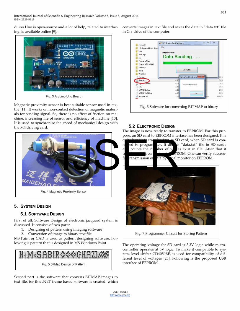
Fig. 7.Programmer Circuit for Storing Pattern
881
IJSER

International Journal of Scientific & Engineering Research Volume 5, Issue 8, August-2014 ISSN 2229-5518
IJSER © 2014
http://www.ijser.org
EEPROM interface is provided such that it uses the same ad-dress in both programmer and the M4 driving card. The de-vice address used is 0x50. In programmer, it is required to transfer data fast so we use page transfer of data, which takes 1–2 seconds to transfer all data in the EEPROM. While in driv-ing card M4 module is operated according to each byte of EEPROM with speed information given by sensor, so we read data byte by byte.
5.3 MECHANICAL DESIGN
Mechanical design consists of two designs. 1. Interfacing with electronic design 2. Interfacing with loom
The first design creates interface for M4 driving card, M4 module and magnetic proximity sensor with mechanical de-sign, are used to synchronize the speed of electronic design with the mechanical design. While second design creates inter-face between loom and mechanical design that synchronizes the speed of loom and mechanical design. Following are the details of mechanical design structure.
The figure above depicts the front and side view of mechanical design of electronic dobby. The components highlighted are,
a) M4 driving card (used for pull down the threads). b) M4 dobby/jacquard module. c) M4 module support d) Magnetic proximity sensor interfacing with M4 mod-
ule support. e) Dobby support stand f) Synchronization of dobby speed with speed of loom.
Details of highlighted components of mechanical design
are: 1. Dobby supports stand (used as joint between dobby
and the loom). 2. Circular plate for transfer of motion.
Fig. 8.USB EEPROM interface
Fig. 9.M4 Driving Card Circuit
(a) (b)
Fig.10.(a) Front and (b) Side View of First Part of Me-
chanical Design
Fig.11.Second Part of Mechanical Design
882
IJSER

International Journal of Scientific & Engineering Research Volume 5, Issue 8, August-2014 ISSN 2229-5518
IJSER © 2014
http://www.ijser.org
3. Small gear casting (Connected to loom shaft). 4. Large gear casting (Connected to dobby). 5. Bearings (To minimize friction).
The following image is shown for pattern designing on fabric.
6. EXPERIMENTAL RESULTS
The table below shows the energy calculation for three cases, the first case is where no dobby is attached to the loom, second when mechanical dobby is installed on the loom and third case is the energy calculation of electronic dobby. It can be clearly understood that about 81KWH of energy is saved for each dobby operation.
TABLE 1
ENERGY CALCULATION
System
Used
Cur-
rent
(Amp)
KVA Power
Factor
(p.f)
KW=
KVA*
p.f
KWH/month=
KW*20hrs*
26days
With-
out
Dobby
12.35 2.717 0.85 2.309 1200
Me-
chani-
cal
Dobby
13.81 3.038 0.85 2.582 1342
Elec-
tronic
Dobby 12.97 2.853 0.85 2.425 1261
The table below shows the money saved for 90 machines in-stalled on test unit. About PKR=123,930/- is saved per month if we replace mechanical dobby with electronic dobby. And sys-tem will cover its instalment cost in 7.3 months.
TABLE 2
COST AND PAYBACK TIME OF ELECTRONIC DOBBY SYSTEM
Power
Saved by one
Electronic
Dobby/month
(Mechanical
Dobby KWH
– Electronic
Dobby
KWH)
Total
KWH
Saved =
Power
Saved by
one Unit x
90Units
PKR
Saved =
Total
KWH
Saved * 17
PKR/KWH
Replacement
Cost of
Electronic
Dobby =
Price of One
Electronic
Dobby * 90
Machines
Payback
Time of
Electronic
Dobby
System
81 KWH 7290KWH 123,930
PKR
900,000
PKR
7.3
Months
Following graphs below depicts a comparison of efficiency of electronic and mechanical dobby at different speed.
The above graph shows efficiency versus RPM characteristics of electronic and mechanical dobby machine. The dotted line shows the response of mechanical dobby while the solid line shows response of electronic dobby. It can be easily realized that at a lower speeds of 50 rpm both machines give 100 per-cent efficiency, but when the speed is increased beyond 50 rpm, their efficiency begin to decrease and at a of speed 100 rpm the mechanical dobby stops working.
Fig. 13.Comparision of Efficeincy and Speed of Mechanical and Electronic Dobby
Fig. 14.Comparision of Design Size and Fault Detection Time
Fig.12. Pattern Designing on Fabric
883
IJSER

International Journal of Scientific & Engineering Research Volume 5, Issue 8, August-2014 ISSN 2229-5518
IJSER © 2014
http://www.ijser.org
The above graph shows fault detection time versus No. of pix-els characteristics. Fault detection is very difficult in mechani-cal system as increasing number of pixels will increase length of punching card chain. If we are using 400 punching cards, then we will have to check all these cards. While in electronic system, it is quite handy to replace any faulty pattern. Fault detection and replacement of faulty part will not take more than 10 minutes time.
In mechanical systems, we have to carefully visualize and de-sign punching card and it is quite difficult and time consum-ing. While in electronic system, one can easily use any imag-ing software to generate BITMAP design and can generate as many designs as needed. Also design is stored in EEPROM device, there is no issue of space for storage of punching cards.
The graph above depicts number of threads breakage versus speed characteristics. It can be observed that in electronic sys-tem, no thread is broken until the speed of 80 rpm of the ma-chine. But with the mechanical system thread breakage is too much at 80 rpm. It has an increasing trend at higher speed but
at the speed of around 90 rpm its stops working and its thread breakage sharply increases.
7. CONCLUSION
The Electronic test unit replaced at R.K. Textiles, Faisalabad is found to be economical and performs better as compared to Mechanical Dobby System. This Electronic Dobby system would be able to pay back its cost in about 7.3 months. More-over, this Electronic system is much lighter in weight, takes lesser volume and easy to dismantle and deploy at any place. Electronic Dobby system can operate even at higher speed than that of 90 rpm, where mechanical dobby can barely achieves a speed of 90 rpm. Also, Electronic Dobby is 2.3 times more power efficient than mechanical Dobby system.
8. ACKNOWLEDGMENT
The authors wish to thank R. K. Textiles, Faisalabad, Pakistan for providing an opportunity to test and deploy Electronic Dobby System. We are also indebted to Department of Electri-cal Engineering, Government College University, GCU, La-hore, Pakistan for rendering lab facilities and technical men-torship to develop this framework.
REFERENCES
[1] Ahmed Salih ,Maged Ali Mohammed Asa'ad Yousif Ahmed, “De-
velopment of an Internet based Embedded System for Smart House
Controlling and Monitoring,” International Journal of Computer
Applications (0975 – 8887) Volume 61– No.14, January 2013
[2] Luca Ferrarini, Jose L. Martinez Lastra, AllanMartel, Antonio Valen-
tini, and Valeriy Vyatkin, “Embedded Systems Design in Intelligent
Industrial Automation,” EURASIP Journal on Embedded Systems
Volume, 2008.
[3] Yousif E.E. Ahmed, Abdo Idris, Fadlelmol Abdallah, “Development
of a Computerized System for Weft Insertion based on Dobby Device
Mechanism,” Gezira Journal for Applied Sciences and Engineering,
Vol No4,pp120 – 136, 2009,
[4] James Essinger, “Jacquard’s Web – How a Hand Loom Led to the
Birth of the Information Age” Oxford: Oxford University Press, 2004
[5] Yousif Elhadi Elsideeq Ahmed, Ali Mahmed Abdelrahman Agoub,
Fadl Elmoula Abdullah Idris, “Experimental Test of Digital Auto-
mated System for Dobby Based Fabric Structure,” Published in IJSER,
Vol. 4, Issue 12, December 2013.
[6] Yamada’s “Dobby Instruction Manual”
[7] Textile Manufacturer Manual ”Dobbies, their mechanism and man-
agement,” CS Department, The University of Arizona.
[8] Peter Jamieson, “Arduino for Teaching Embedded Systems. Are
Computer Scientists and Engineering Educators Missing the Boat?”
Miami University, Oxford, OH, 45056
[9] M. Pedroni, T. Bay, M. Oriol, and A. Pedroni, “Open source projects
in programming courses,” SIGCSE Bull., vol. 39, pp. 454–458, March
2007.
[10] Jagiella, M.; Fericean, S.; Droxler, R., "New Non-contacting Linear Displacement Inductive Sensors for Industrial Automation," Sensors, 2006. 5th IEEE Conference on , vol., no., pp.534,537, 22-25 Oct. 2006doi: 10.1109/ICSENS.2007.355523
Fig. 15.Comparision of Pixel Designing Time and Number of Pixels
Fig. 16.Comparision of Speed of Mechanical and Thread Break-age
884
IJSER

International Journal of Scientific & Engineering Research Volume 5, Issue 8, August-2014 ISSN 2229-5518
IJSER © 2014
http://www.ijser.org
[11] Anannya Mukherjee, “Process Automation versus Power System
Automation,” International Journal of Scientific & Engineering Re-
search, Volume 4, Issue 10, October-2013.
[12] Paduri Veerabhadram, “Applications of Robotics in Medicine”. In-
ternational Journal of Scientific & Engineering Research Volume 2,
Issue 8, Auguest-2011
[13] Ahmed Yousif, idris, Fadlelmol, idris, Abdo, “Development of a
Computerized System for Weft Insertion based on Dobby Device
Mechanism,” Gezira J. for Applied Sciences and Engineering, Vol.
No4,pp120 -136, 2009.
[14] Abhishek Dwivedi, Avanish Dwivedi. “Role of Computer and Au-
tomation in Design and Manufacturing for Mechanical and Textile
Industries: CAD/CAM,” International Journal of Innovative Technol-
ogy and Exploring Engineering (IJITEE) ISSN: 2278-3075, Volume-3,
Issue-3, August 2013.
[15] Radha R.C, Ravuri Aneesh Kumar, “Design and Implementation of
I2C Communication Protocol on FPGA for EEPROM”. International
Journal of Scientific & Engineering Research, Volume 5, Issue 3,
March-2014.
885
IJSER