Embed Size (px)
Citation preview
16TH INTERNATIONAL CONFERENCE ON COMPOSITE MATERIALS
CO
Ryohei
K
Abstract
The evacharacteristics and the reliabstructures. In tpresented for thfracture toughnresidual stresseasymmetric adhtemperature chaexpansion betwresultant residumoments in the incorporated in fracture mechanproperties areevaluation of present methodverification teststhe adhesive temperature acorrection metho
1 Introduction
The develoAl alloy liner hcryogenic fuelvehicles [1]. Hbetween CFRP structural test. Iof thermal shrinadhesives resulSevere thermal tank structures dof thermal expanand the adhesibetween the mo
FRACTURE TOUGHNESS EVALUATION OF MPOSITE/METAL ADHESIVE STRUCTURE IN
CRYOGENIC ENVIRONMENT
Maruyama*, Tomohiro Yokozeki **, Toshio Ogasawara*** , Takeshi Ogawa** Aoyamagakuin University, **The University of Tokyo,
*** Japan Aerospace Exploration Agency
eywords: Adhesive, Thermal Residual Stress, Fracture Toughness, DCB test
luation of adhesive fracture is important to enhance the safety ility of composite/metal adhesive his study, an analytical method is e evaluation of the correct adhesive ess including the effect of thermal s in the case of symmetric and esive DCB tests. Because of the nge and the difference of thermal
een adherends and adhesives, the al thermal stresses induce bending test specimen, and thus, this effect is the present method to evaluate the ics properties accurately. Material experimentally measured for residual thermal stress, and the is validated by experimental . Finally, the experimental results of fracture toughness at cryogenic re presented, and the present dology is demonstrated.
pment of CFRP tank structures with as been attempted for light-weight storage system of space launch owever, the onset of debondings
and Al liner was reported during the t has been considered that the misfit kage among CFRP, Al alloy, and ts in this composite tank failure. residual stresses are induced in the ue to the difference in coefficients sion (CTEs) between the adherends
ves when there exist differences lding temperature and the service
Fig. 1. Double cantilever beam (DCB) test
temperature [2]. The fracture characteristics evaluation of the adhesive bonded structures is important to advance the safety and the reliability of cryogenic composite tanks [3].
Double cantilever beam (DCB) tests (Fig.1) is enumerated as standard evaluation tests of the fracture mechanics characteristics in the bonded structures (e.g. JIS and ASTM). However, these standards do not include the effect of thermal residual stresses. It is necessary to consider the effect of thermal residual stresses on the evaluation of fracture toughness [4], specifically under a low temperature environment, where the influence may become much remarkable. Nairn also showed the necessity of the correction for this problem [4]. He derived the correction method that includes the influence of thermal residual stress in the energy release rates of DCB specimens which have identical upper and lower adherends, and crack progressing at the center of the adhesive (i.e. symmetric DCB specimens) [4].
In this study, an analytical method is presented for the evaluation of the correct adhesive fracture toughness including the effect of thermal residual stresses in the case of DCB test. This method is
1
RYOHEI MARUYAMA, T Yokozeki , T Ogasawara , T Ogawa
validated by experimental verification tests, and the material characterizations are measured by the experiment for evaluating thermal residual stress. Finally, DCB test was performed using composite materials/aluminum alloy bonded specimens that simulated composite tank structures with metal liners. Further more the experimental results on the adhesive fracture toughness at cryogenic temperature are presented, and the present correction methodology is applied. Methodology and experimental results on the accurate evaluation of adhesive fracture toughness is presented in this study, which is considered to contribute the development of the reliable metal-liner composite tank structures.
2 Correction method for adhesive fracture toughness
2.1Correction method [5]
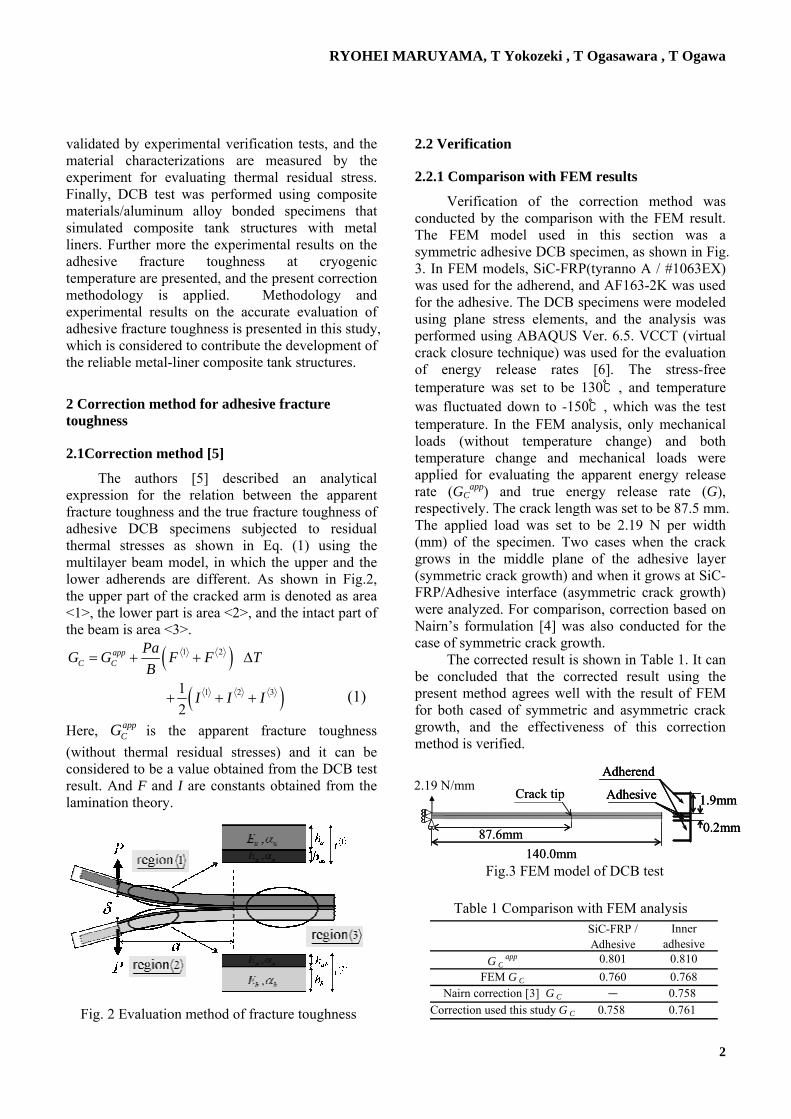
The authors [5] described an analytical expression for the relation between the apparent fracture toughness and the true fracture toughness of adhesive DCB specimens subjected to residual thermal stresses as shown in Eq. (1) using the multilayer beam model, in which the upper and the lower adherends are different. As shown in Fig.2, the upper part of the cracked arm is denoted as area <1>, the lower part is area <2>, and the intact part of the beam is area <3>.
( )( )
1 2
1 2 312
appC C
PaG G F F TB
I I I
= + + ∆
+ + +
Here, is the apparent fracture toughness (without thermal residual stresses) and it can be considered to be a value obtained from the DCB test result. And F and I are constants obtained from the lamination theory.
appCG
2.2 Verification
2.2.1 Comparison with FEM results
Verification of the correction method was conducted by the comparison with the FEM result. The FEM model used in this section was a symmetric adhesive DCB specimen, as shown in Fig. 3. In FEM models, SiC-FRP(tyranno A / #1063EX) was used for the adherend, and AF163-2K was used for the adhesive. The DCB specimens were modeled using plane stress elements, and the analysis was performed using ABAQUS Ver. 6.5. VCCT (virtual crack closure technique) was used for the evaluation of energy release rates [6]. The stress-free temperature was set to be 130℃, and temperature was fluctuated down to -150℃, which was the test temperature. In the FEM analysis, only mechanical loads (without temperature change) and both temperature change and mechanical loads were applied for evaluating the apparent energy release rate (GC
app) and true energy release rate (G), respectively. The crack length was set to be 87.5 mm. The applied load was set to be 2.19 N per width (mm) of the specimen. Two cases when the crack grows in the middle plane of the adhesive layer (symmetric crack growth) and when it grows at SiC-FRP/Adhesive interface (asymmetric crack growth) were analyzed. For comparison, correction based on Nairn’s formulation [4] was also conducted for the case of symmetric crack growth.
The corrected result is shown in Table 1. It can be concluded that the corrected result using the present method agrees well with the result of FEM for both cased of symmetric and asymmetric crack growth, and the effectiveness of this correction method is verified.
(1)
2.16 N/mm
Fig. 2 Evaluation method of fracture toughness
Table 1 Comparison with FEM analysis
Fig.3 FEM model of DCB test
Crack tip
87.6mm140.0mm
Adherend
Adhesive 1.9mm
0.2mm
2.16 N/mm Crack tip
87.6mm140.0mm
Adherend
Adhesive 1.9mm
0.2mm
Adherend
Adhesive 1.9mm
0.2mm
2.19 N/mm
SiC-FRP /Adhesive
Inneradhesive
G Capp 0.801 0.810
FEM G C 0.760 0.768Nairn correction [3] G C - 0.758
Correction used this study G C 0.758 0.761
2
FRACTURE TOUGHNESS EVALUATION OF COMPOSITE/METAL ADHESIVE STRUCTURE IN CRYOGENIC ENVIRONMENT
2.2.2 Experimental verification test
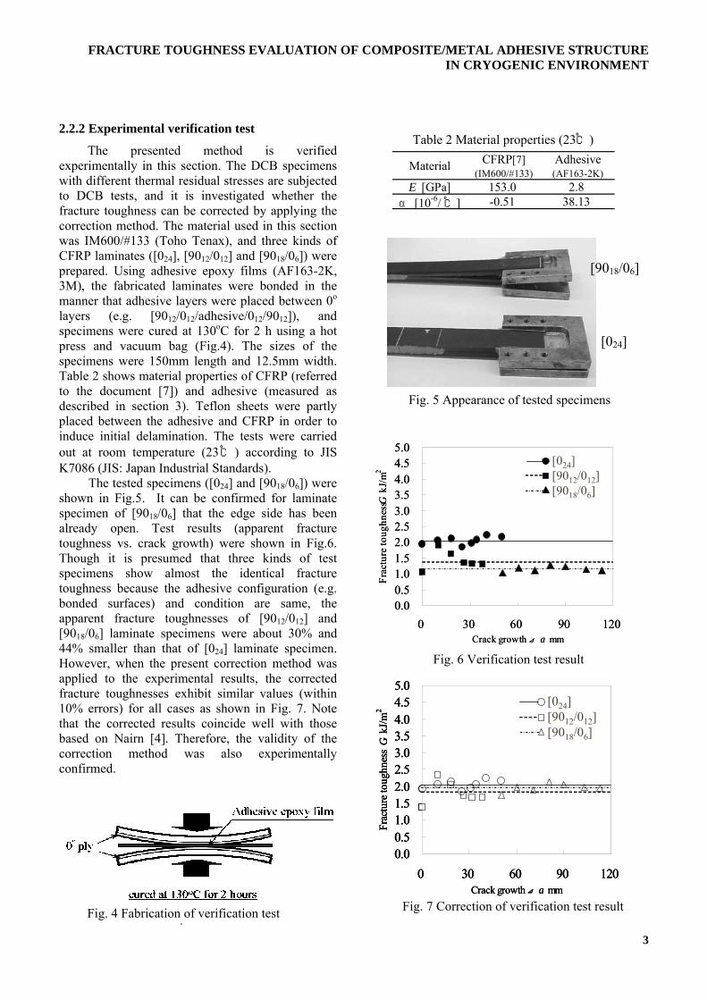
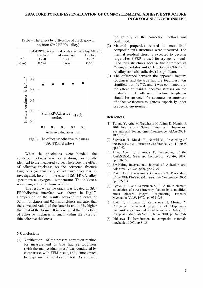
The presented method is verified experimentally in this section. The DCB specimens with different thermal residual stresses are subjected to DCB tests, and it is investigated whether the fracture toughness can be corrected by applying the correction method. The material used in this section was IM600/#133 (Toho Tenax), and three kinds of CFRP laminates ([024], [9012/012] and [9018/06]) were prepared. Using adhesive epoxy films (AF163-2K, 3M), the fabricated laminates were bonded in the manner that adhesive layers were placed between 0o layers (e.g. [9012/012/adhesive/012/9012]), and specimens were cured at 130oC for 2 h using a hot press and vacuum bag (Fig.4). The sizes of the specimens were 150mm length and 12.5mm width. Table 2 shows material properties of CFRP (referred to the document [7]) and adhesive (measured as described in section 3). Teflon sheets were partly placed between the adhesive and CFRP in order to induce initial delamination. The tests were carried out at room temperature (23℃ ) according to JIS K7086 (JIS: Japan Industrial Standards). The tested specimens ([024] and [9018/06]) were shown in Fig.5. It can be confirmed for laminate specimen of [9018/06] that the edge side has been already open. Test results (apparent fracture toughness vs. crack growth) were shown in Fig.6. Though it is presumed that three kinds of test specimens show almost the identical fracture toughness because the adhesive configuration (e.g. bonded surfaces) and condition are same, the apparent fracture toughnesses of [9012/012] and [9018/06] laminate specimens were about 30% and 44% smaller than that of [024] laminate specimen. However, when the present correction method was applied to the experimental results, the corrected fracture toughnesses exhibit similar values (within 10% errors) for all cases as shown in Fig. 7. Note that the corrected results coincide well with those based on Nairn [4]. Therefore, the validity of the correction method was also experimentally confirmed.
Table 2 Material properties (23℃)
Material CFRP[7](IM600/#133)
Adhesive(AF163-2K)
E [GPa] 153.0 2.8α [10-6/ ℃] -0.51 38.13
[9018/06]
[024] Fig. 5 Appearance of tested specimens
0.00.51.01.52.02.53.03.54.04.55.0
0 30 60 90 120Crack growth ⊿ a mm
Frac
ture
toug
hnes
s k
J/m
Fig. 4 Fabrication of verification test i
Fig. 6 Verification test result
G2
[024][9012/012][9018/06]
[024][9012/012][9018/06]
0.00.51.01.52.02.53.03.54.04.55.0
0 30 60 90 120Crack growth ⊿ a mm
Frac
ture
toug
hnes
s k
J/m
[024][9012/012][9018/06]
[024][9012/012][9018/06]
[024][9012/012][9018/06]G
2
0.00.51.01.52.02.53.03.54.04.55.0
0 30 60 90 12Crack growth ⊿a mm
Frac
ture
toug
hnes
s G
kJ/m
Fig. 7 Correction of verification test result
0
2
[024][9012/012][9018/06]
[024][9012/012][9018/06]
0.00.51.01.52.02.53.03.54.04.55.0
0 30 60 90 120Crack growth ⊿a mm
Frac
ture
toug
hnes
s G
kJ/m
2
[024][9012/012][9018/06]
[024][9012/012][9018/06]
0.00.51.01.52.02.53.03.54.04.55.0
0 30 60 90 120Crack growth ⊿a mm
Frac
ture
toug
hnes
s G
kJ/m
[024][9012/012][9018/06]
[024][9012/012][9018/06]
2
3

RYOHEI MARUYAMA, T Yokozeki , T Ogasawara , T Ogawa
3 Experimental procedure
3.1 Mechanical properties
Mechanical properties are necessary for evaluation of the thermal residual stress and strain. Materials used in this study were CFRP(MR50 /#1063EX, [0]16, Mitsubishi Rayon Japan), SiC-FRP (Tyranno A, Ube Industries / #1063EX, [0]16), A6061-T6, and adhesive films (AF163-2K,3M). #1063EX is tough epoxy resin for the aircraft made by Mitsubishi Rayon Japan. Tension tests were conducted according to JIS Z 2241, K 7113, and K7073 at 23℃ (room temperature) and -196℃(specimens were soaked in LN2). In order to measure the shear modulus, mechanical properties (E45 and ν45) measured using 45 ゚ test specimens were utilized according to the following equation [8].
( ){ }45
45
12 ν+=
EG
(2)
3.2 Thermal expansion
Thermal expansion behavior was evaluated using a laser dilatometer LIX-1 (ULVAC-RIKO) (Fig.8). Fig.9 showed the conformation of LIX-1. After filling liquid nitrogen in a thermostatic chamber, temperature increased at a constant heating rate. The displacement ∆L and the temperature T of test specimen were measured. The thermal strain ε was calculated from initial length L and ∆L, and the liner (tangential) coefficient of thermal expansion α was calculated from ε and ∆T. The heating rate of temperature change was set to be 1.0℃ /min. Moreover, mean coefficient of thermal expansion α‘ at 23 ℃ and -150 ℃ was calculated by using the obtained linear thermal expansion coefficient and the trapezoidal method under the condition that stress free temperature is assumed to be the molding temperature, 130 ℃.
Laser interferometer
Vacuum pump
Measuring circuit of thermal expansion
Thermal controller
Temperature-measuring device
PC
Specimen Thermostatic chamber
Laser interferometer
Vacuum pump
Measuring circuit of thermal expansion
Thermal controller
Temperature-measuring device
PC
Specimen Thermostatic chamber
Fig.9 Conformation of LIX-1
3.3 Ad
Icharacpresenconsidstressecharacperformethostandacracksspecimsubjecof 0.5machiused acomplappare
Fig.10compospecimwith mtempematerispecim12.5mFRP (T6) wfor the
5mm
15mm
Fig.8 Laser dilatometer LIX-1 (ULVAC-RIKO) and Thermal expansion test specimen
Fig.10 Adhesive DCB test specimen (FRP 0 ゚/Adhesive/Al alloy)
hesive fracture toughness
n this section, fracture mechanics terization of FRP/metal adhesive structures is ted. FRP/metal adhesive structures are ered to be subjected to severe residual thermal s under cryogenic conditions. Experimental terization of adhesive fracture toughness is med combined with the present correction d. DCB tests were performed according to the rd (JIS K7086, ASTM D3433). The initial were introduced using release films, and ens were cured at 130oC. The specimens were
ted to the vertical load P, at a crosshead speed or 1mm/min using a mechanically driven ne. The displacement of the crosshead was s the crack opening displacement (COD). The iance method was used to evaluate the nt fracture toughness in this study. The specimen configuration is shown in . The DCB tests were performed using site materials/aluminum alloy bonded ens that imitate composite tank structures etal liners. The tests were conducted at room
rature and at -196℃. Two kinds of composite als (CFRP and SiC-FRP) were prepared. The en size was set to be 150mm in length and
m in width. CFRP (MR50 / #1063EX), SiC-tyranno A / #1063EX), and Al alloy (A6061-ere used for the adherend. AF163-2K was used adhesive. Asymmetric DCB specimens with
4

FRACTURE TOUGHNESS EVALUATION OF COMPOSITE/METAL ADHESIVE STRUCTURE IN CRYOGENIC ENVIRONMENT
different adherends (e.g. FRP upper adherend and Al alloy lower adherend) were prepared, and the adhesive fracture toughness was evaluated.
4 Result and discussion
4.1 Mechanical properties and thermal expansion
Test results were shown Table 3 and 4, which suggest that CFRP is stiffer than SiC-FRP in 0o direction but the latter have higher 90o stiffness than the former. The CTE of CFRP is low in 0o direction compared to that of SiC-FRP. Therefore, it can be concluded that the CTE difference between CFRP and A6061-T6 (and AF163-2K) is significant compared to that between SiC-FRP and A6061-T6 (and AF163-2K). The thermal residual stress is expected to become large when CFRP is used for cryogenic metal-lined tank structures because the difference of the Young's modulus is also significant.
4.2 Adhesive fracture toughness and correction results
The load-COD curves obtained from the experiments were shown in Fig.11 and 12. The crack growth was observed at the interface between FRP and adhesive (FRP/Adhesive interface) at the -196oC, while the crack propagated in the adhesive layer at 23 oC. The stick-slip phenomenon was observed at cryogenic temperature, whereas stable crack growth was observed at room temperature. The stick-slip phenomenon was especially significant in CFRP/Al alloy specimens at -196oC. Therefore, the fracture
toughness of CFRP/Al alloy specimens at -196oC was able to be acquired only at an initial stage of the crack growth. The correction method was applied to the obtained apparent fracture toughness. The crack growth in the adhesive layer was observed at 23oC. And the crack growth at the interface between FRP and adhesive was observed at -196oC. The results were shown in Fig. 13, 14, 15 and 16. In the graphs, the apparent fracture toughness obtained from experiment and corrected result is denoted as GC
app and GC, respectively. Here, the stress free temperature was assumed to be 130oC that was the molding temperature of the test specimen in the correction. The corrected result, GC, was higher than the apparent fracture toughness, GC
app, in all cases in this section. In asymmetric DCB specimens examined in this section, energy release rates due to temperature change (the third term in equation (1)) are relatively large, and are dominant for the correction. The difference between GC, and GC
app is 1-3% at 23oC in both asymmetric DCB specimens. However, there is significant difference (more than twice) between GC and GC
app at -196oC. It is thought that the difference of thermal strain had been induced due to high temperature difference and the rigidity of each material increased at cryogenic temperature. Especially, it turned out that the influence was large for the CFRP/Al alloy test specimen. Therefore, it is concluded that the effect of residual thermal stress on the fracture toughness evaluation should be corrected at cryogenic temperature. It will be necessary to develop a correction method for other fracture mechanics tests (e.g. end-notched flexure) of adhesive structures such as cryogenic composite tanks.
Table 3 Material properties (23℃)
Material SiC-FRP(TyrannoA/#1063EX)
CFRP(MR50/#1063EX)
Adhesive(AF163-2K)
Al alloy(A6061-T6)
0° 89.8 163.190° 13.5 8.7
G [GPa] 4.12 4.50° 0.28 0.3390° 0.05 0.020° 2.18 -0.0290° 14.01 -
E
Table 4 Material properties (α:-150℃, Others:-196℃)
Material SiC-FRP(TyrannoA/#1063EX)
CFRP(MR50/#1063EX)
Adhesive(AF163-2K)
Al alloy(A6061-T6)
0° 88.1 161.390° 28.6 12.7
G [GPa] 10.8 12.60° 0.28 0.3590° 0.09 0.020° 0.28 -0.1990° 14.01 -
α
[10-6/ ℃]25.97 15.55
E [GPa] 9.7 77.1
ν 0.44 0.35
[GPa]
ν
α
[10-6/ ℃] 38.13 18.67
2.8 69.8
0.330.32
SiC-FRP/Al alloy 0
20
40
6080
100
120
140
0 20 40 60 80Crack opening displacement mm
Load
N
23℃-196℃
Fig.11 Load-COD plot by SiC-FRP/Al alloy
5

RYOHEI MARUYAMA, T Yokozeki , T Ogasawara , T Ogawa
0
20
40
6080
100
120
140
0 20 40 60 80Crack opening displacement mm
Load
N
23℃-196℃
0.0
0.5
1.0
1.5
2.0
0 10 20 30 40 50Crack growth ⊿a mm
Crit
ical
Fra
ctur
e En
ergy
G[k
J/m2 ]
4.3 Influence of the crack plane position and the adhesive thickness
The effect of crack plane position (e.g. crack at interface or crack in the adhesive layer) on the corrected fracture toughness is investigated in this section, because the corrected results depend on the position of crack plane. Three cases (crack growth at SiC-FRP/adhesive interface, crack growth in the middle plane of adhesive layer, and crack growth at Al alloy/adhesive interface) are examined, and the comparative results are shown in Table 4. It was demonstrated that the corrected values depend on the crack position (about 15%) at -196oC, while the crack position has little influence on the fracture toughness evaluation at 23oC. Therefore, observation of crack growth position is necessary for correcting the fracture toughness accurately.
C Gcapp
Gc
Gcapp
Gc
SiC-FRP/Al alloy
0.0
0.5
1.0
1.5
2.0
0 10 20 30 40 50Crack growth ⊿a mm
Crit
ical
Fra
ctur
e En
ergy
G[k
J/m2 ]
Gcapp
Gc
Gcapp
Gc
SiC-FRP/Al alloyC
CFRP/Al alloy
Fig.12 Load-COD plot by CFRP/Al alloy Fig.15 Fracture toughness of SiC-FRP/Al alloy (-196℃)
0.0
0.5
1.0
1.5
2.0
0 10 20 30 40 50Crack growth ⊿a mm
Crit
ical
Fra
ctur
e En
ergy
GC
[kJ/m
2 ]GcappGc
Gcapp
Gc
CFRP/Al alloy
0.0
0.5
1.0
1.5
2.0
0 10 20 30 40 50Crack growth ⊿a mm
Crit
ical
Fra
ctur
e En
ergy
GC
[kJ/m
2 ]GcappGc
Gcapp
Gc
CFRP/Al alloy
0.00.51.01.52.02.53.03.54.0
Fig.16 Fracture toughness of CFRP/Al alloy (-196℃)
0.00.51.01.52.02.53.03.54.0
0 10 20 30 40 50 60 70 80Crack growth ⊿a mm
Crit
ical
Fra
ctur
e En
ergy
GC
[kJ/m
2 ]
Gcapp
Gc
Gcapp
GcCFRP/Al alloy0.00.51.01.52.02.53.03.54.0
0 10 20 30 40 50 60 70 80Crack growth ⊿a mm
Crit
ical
Fra
ctur
e En
ergy
GC
[kJ/m
2 ]
Gcapp
Gc
Gcapp
GcCFRP/Al alloy
Fig.14 Fracture toughness of CFRP/Al alloy (23℃)
0 10 20 30 40 50 60 70 80Crack growth ⊿a mm
[kJ/m
2 ]C
ritic
al F
ract
ure
Ener
gy G
C
Gcapp
Gc
Gcapp
GcSiC-FRP/Al alloy0.00.51.01.52.02.53.03.54.0
0 10 20 30 40 50 60 70 80Crack growth ⊿a mm
[kJ/m
2 ]C
ritic
al F
ract
ure
Ener
gy G
C
Gcapp
Gc
Gcapp
GcSiC-FRP/Al alloy
Fig.13 Fracture toughness of SiC-FRP/Al alloy (23℃)
6
FRACTURE TOUGHNESS EVALUATION OF COMPOSITE/METAL ADHESIVE STRUCTURE IN CRYOGENIC ENVIRONMENT
When the specimens were
adhesive thickness was not uniformidentical to the measured value. Thereof adhesive thickness on the corrtoughness (or sensitivity of adhesivinvestigated, herein, in the case of SiCspecimens at cryogenic temperature.was changed from 0.1mm to 0.5mm.
The result when the crack was FRP/adhesive interface was showComparison of the results between0.1mm thickness and 0.5mm thicknesthe corrected value of the latter is abthan that of the former. It is concludedof adhesive thickness is small withithin adhesive thickness.
5 Conclusions
(1) Verification of the present corfor measurement of true fract(with thermal residual stress) wacomparison with FEM result, anby experimental verification tes
the validity of the correction method was confirmed. Table 4 The effect by difference of crack growth
position (SiC-FRP/Al alloy) (2) Material properties related to metal-lined composite tank structures were measured. The thermal residual stress is expected to become large when CFRP is used for cryogenic metal-lined tank structures because the difference of Young's modulus and CTE between CFRP and Al alloy (and also adhesive) is significant.
SiC-FRP/AdhesiveInterface
middle plane ofadhesive layer
Al alloy/AdhesiveInterface
23℃ 3.290 3.300 3.297-196℃ 0.694 0.609 0.651
(3) The difference between the apparent fracture toughness and the true fracture toughness was significant at -196oC, and it was confirmed that the effect of residual thermal stresses on the evaluation of adhesive fracture toughness should be corrected for accurate measurement of adhesive fracture toughness, especially under cryogenic environment.
0.0
0.2
0.4
0.6
0.8
0.1 0.2 0.3 0.Adhesive thickness
Frac
ture
toug
hnes
s G
kJ/m
m2
SiC-FRP/Adhesive interface
Fig.17 The effect by adhesive (SiC-FRP/Al alloy)
bonded, the , nor locally
fore, the effect ected fracture e thickness) is -FRP/Al alloy
The thickness
located at SiC-n in Fig.17. the cases of s indicates that out 5% higher that the effect n the cases of
rection method ure toughness s conducted by d demonstrated t. As a result,
4 0.5 mm
-196℃ References
[1] Torano Y, Arita M, Takahashi H, Arima K, Namiki F, 10th International Space Planes and Hypersonic Systems and Technologies Conference, AIAA-2001-1877, 2001
thickness
[2] Suemasu H., Maeda Y., Namiki M., Proceeding of the JSASS/JSME Structure Conference, Vol.47, 2005, pp.60-62.
[3] J.He, Aoki T, Shimoda T, Proceeding of the JSASS/JSME Structure Conference, Vol.46, 2004, pp.158-160.
[4] J.A.Nairn, International Journal of Adhesion and Adhesive, Vol.20, 2000, pp.59-70
[5] Yokozeki T.,Maruyama R.,Ogasawara T., Proceeding of the 48th JSASS/JSME Structure Conference, 2006, pp.282-284
[6] Rybicki,E.F. and Kamminen.M.F. A finite element calculation of stress intensity factors by a modified crack closure integral Engineering Fracture Mechanics Vol.9, 1977, pp.931-938
[7] Aoki T, Ishikawa T, Kumazawa H, Morino Y Cryogenic mechanical properties of CF/polymer composites for tanks of reusable rockets Advanced Composite Materials Vol.10, No.4, 2001, pp.349-356
[8] Ishikawa T, Introduction to composite materials mechanics 1997, pp.8-13
7