Embed Size (px)
Citation preview
FR-A800 Series Inverters
New publication effective June 2013.Specifications subject to change without notice.
Printed in Japan (iPLANET)©2013 MITSUBISHI ELECTRIC CORPORATION. ALL RIGHTS RESERVED.
FR-A800 Series INVERTERs
First-class Drive Performance
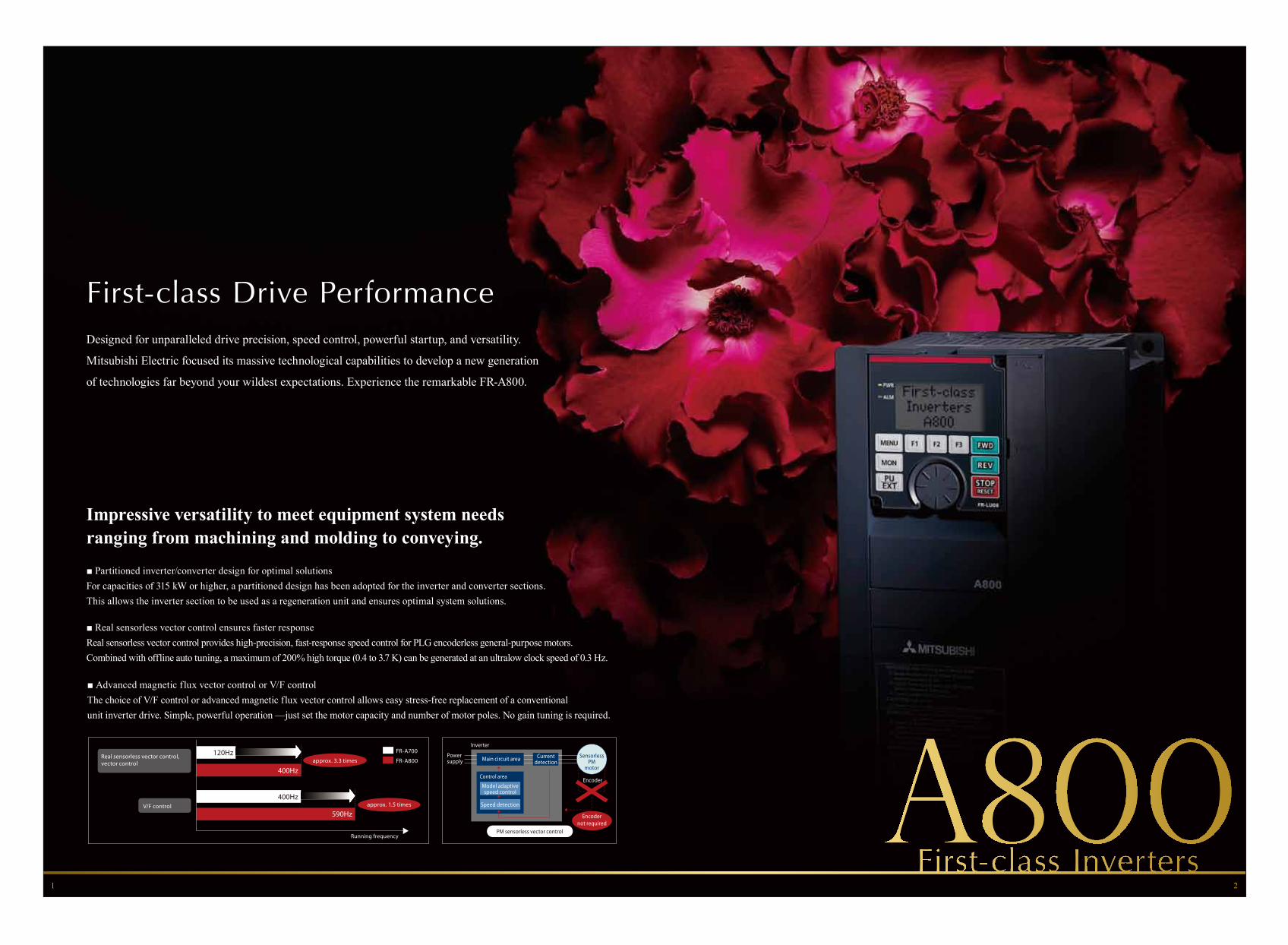
Impressive versatility to meet equipment system needs ranging from machining and molding to conveying.
■ Partitioned inverter/converter design for optimal solutionsFor capacities of 315 kW or higher, a partitioned design has been adopted for the inverter and converter sections. This allows the inverter section to be used as a regeneration unit and ensures optimal system solutions.
■ Real sensorless vector control ensures faster responseReal sensorless vector control provides high-precision, fast-response speed control for PLG encoderless general-purpose motors. Combined with offline auto tuning, a maximum of 200% high torque (0.4 to 3.7 K) can be generated at an ultralow clock speed of 0.3 Hz.
■ Advanced magnetic flux vector control or V/F controlThe choice of V/F control or advanced magnetic flux vector control allows easy stress-free replacement of a conventionalunit inverter drive. Simple, powerful operation —just set the motor capacity and number of motor poles. No gain tuning is required.
Designed for unparalleled drive precision, speed control, powerful startup, and versatility.
Mitsubishi Electric focused its massive technological capabilities to develop a new generation
of technologies far beyond your wildest expectations. Experience the remarkable FR-A800.
1 2
FR-A800
FR-A700120Hz
400Hz
590Hz
400Hz
Running frequency
approx. 3.3 times
approx. 1.5 times
Real sensorless vector control,vector control
V/F control
Powersupply
Inverter
SensorlessPM
motor
PM sensorless vector control
Main circuit area
Encoder
Encodernot required
Currentdetection
Control area
Speed detection
Model adaptivespeed control
First-class Eco Performance
Boost productivity while saving energy with next-generation eco performance.
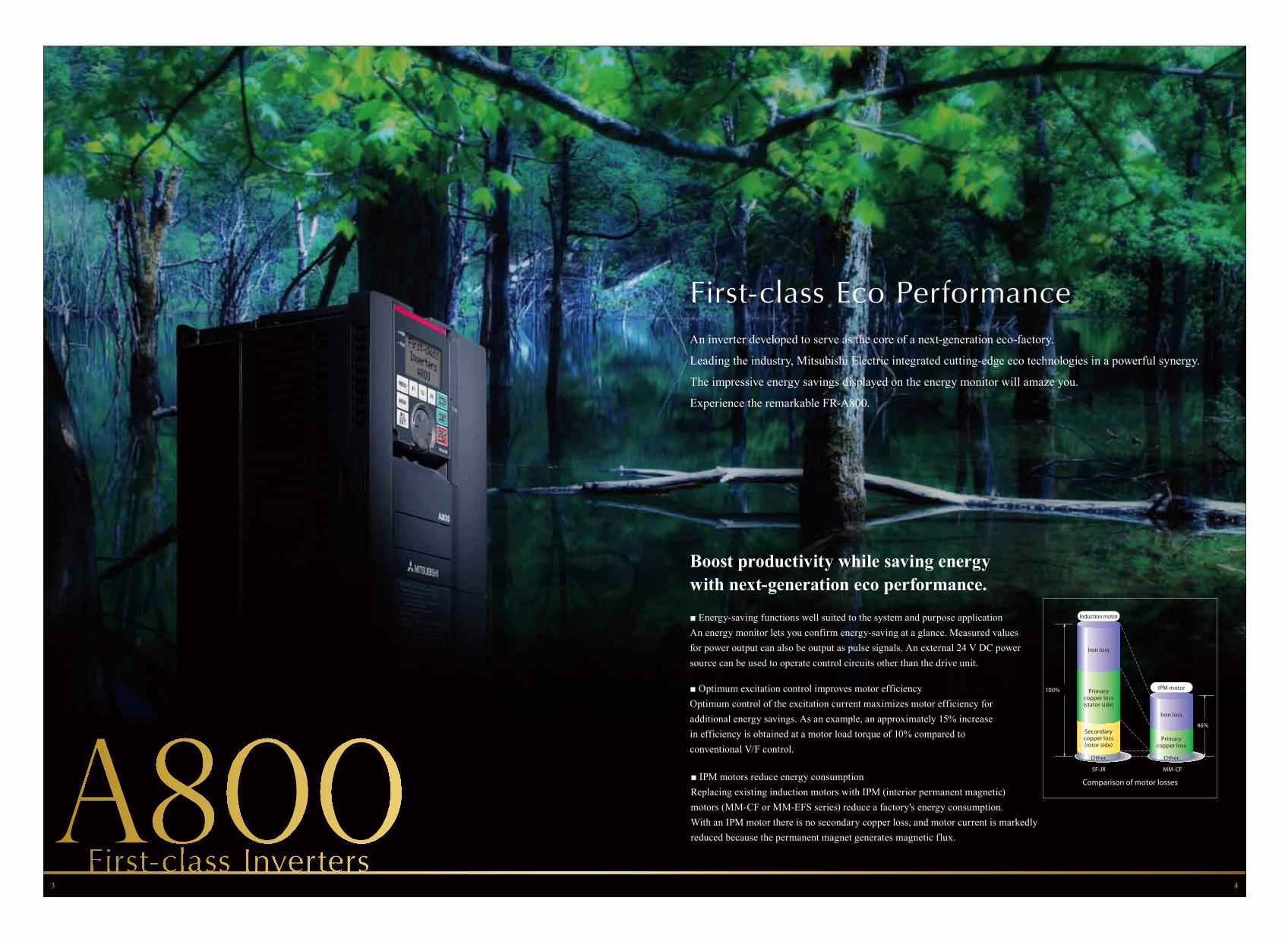
■ Energy-saving functions well suited to the system and purpose applicationAn energy monitor lets you confirm energy-saving at a glance. Measured valuesfor power output can also be output as pulse signals. An external 24 V DC powersource can be used to operate control circuits other than the drive unit.
■ Optimum excitation control improves motor efficiencyOptimum control of the excitation current maximizes motor efficiency foradditional energy savings. As an example, an approximately 15% increasein efficiency is obtained at a motor load torque of 10% compared toconventional V/F control.
■ IPM motors reduce energy consumptionReplacing existing induction motors with IPM (interior permanent magnetic)motors (MM-CF or MM-EFS series) reduce a factory's energy consumption.With an IPM motor there is no secondary copper loss, and motor current is markedlyreduced because the permanent magnet generates magnetic flux.
An inverter developed to serve as the core of a next-generation eco-factory.
Leading the industry, Mitsubishi Electric integrated cutting-edge eco technologies in a powerful synergy.
The impressive energy savings displayed on the energy monitor will amaze you.
Experience the remarkable FR-A800.
Comparison of motor losses
100%
46%
SF-JR MM-CF
Induction motor
IPM motor
Primarycopper loss
Iron loss
Other
Iron loss
Primarycopper loss(stator side)
Secondarycopper loss(rotor side)
Other
3 4

First-class Usability Performance
Compliant with global standards and equipped with a multi-language LCD parameter unit.
■ Multi-language LCD parameter unitA new multi-language LCD parameter unit features enhanced display and clock functions,with 8-language capability scheduled for October 2013. More languages will be gradually added.
■ Inverter complies with European EMC DirectiveThe inverter's built-in EMC filter ensures full compliance with European EMC Directive standards,so separate certification is not required for the inverter. Newly developed drive technology andpower supply technology significantly reduce electromagnetic noise.
■ Global complianceCompliance with the world's most demanding standards — including the United States’ UL standards,Canada’s cUL standards, and Europe’s EC Directive (CE Mark) — means that installation andoperation are possible in any location and for any application.
Created for ease of use in any factory anywhere in the world.
Mitsubishi Electric used its wealth of engineering expertise acquired serving
the global market to achieve the ultimate in intuitive operation. Experience the remarkable FR-A800
5 6
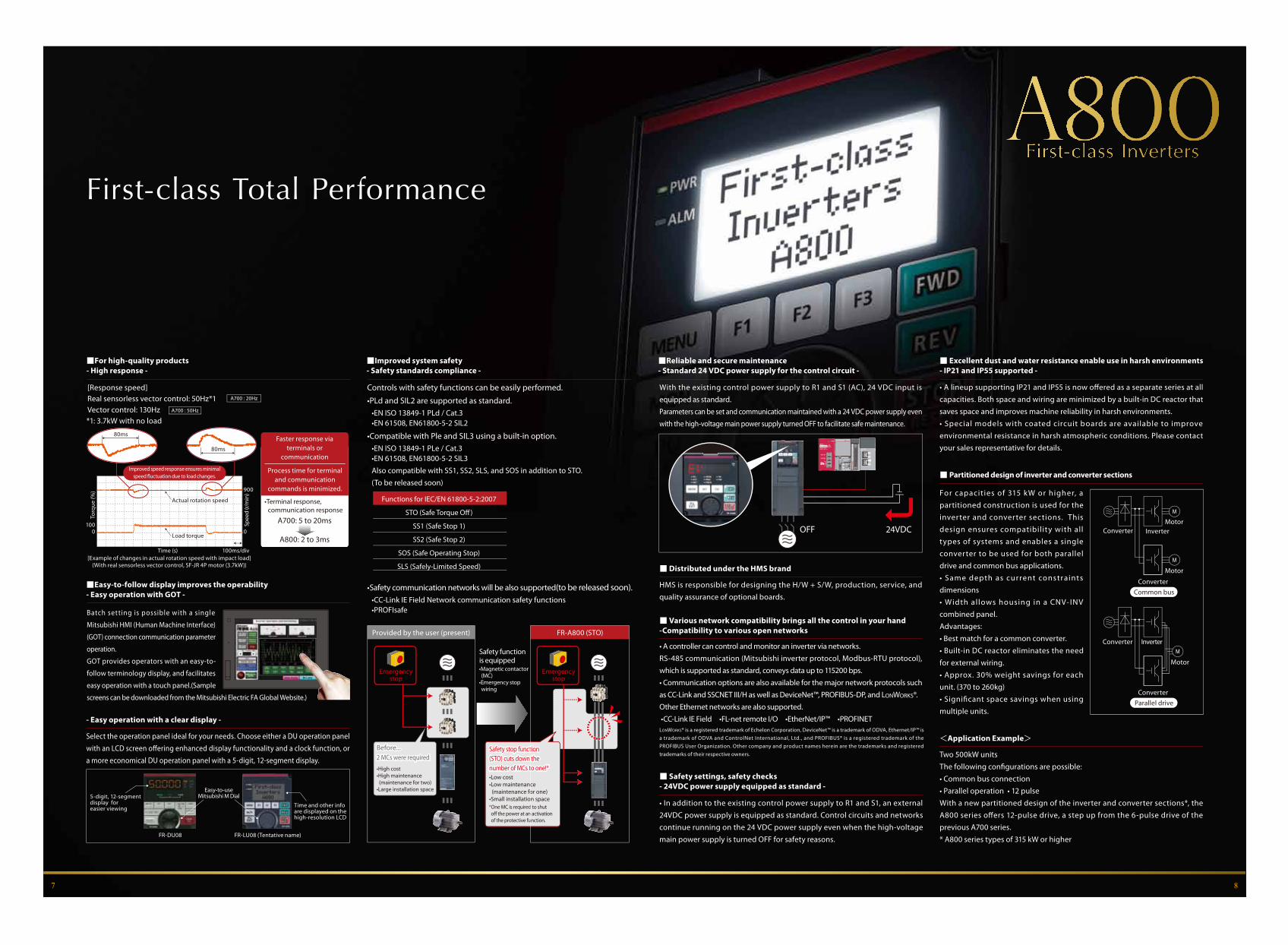
First-class Total Performance
5-digit, 12-segmentdisplay foreasier viewing Time and other info
are displayed on the high-resolution LCD
Easy-to-useMitsubishi M Dial
FR-DU08 FR-LU08 (Tentative name)
- Easy operation with a clear display -
Select the operation panel ideal for your needs. Choose either a DU operation panel with an LCD screen o�ering enhanced display functionality and a clock function, or a more economical DU operation panel with a 5-digit, 12-segment display.
■ Safety settings, safety checks- 24VDC power supply equipped as standard -
• In addition to the existing control power supply to R1 and S1, an external 24VDC power supply is equipped as standard. Control circuits and networks continue running on the 24 VDC power supply even when the high-voltage main power supply is turned OFF for safety reasons.
■ Excellent dust and water resistance enable use in harsh environments- IP21 and IP55 supported -
• A lineup supporting IP21 and IP55 is now offered as a separate series at all capacities. Both space and wiring are minimized by a built-in DC reactor that saves space and improves machine reliability in harsh environments.• Special models with coated circuit boards are available to improve environmental resistance in harsh atmospheric conditions. Please contact your sales representative for details.
■ Distributed under the HMS brand
HMS is responsible for designing the H/W + S/W, production, service, and quality assurance of optional boards.
<Application Example>
Two 500kW unitsThe following con�gurations are possible:• Common bus connection• Parallel operation • 12 pulseWith a new partitioned design of the inverter and converter sections*, the A800 series offers 12-pulse drive, a step up from the 6-pulse drive of the previous A700 series.* A800 series types of 315 kW or higher
■ Partitioned design of inverter and converter sections
For capacities of 315 kW or higher, a partitioned construction is used for the inverter and converter sections. This design ensures compatibility with all types of systems and enables a single converter to be used for both parallel drive and common bus applications. • Same depth as current constraints dimensions• Width allows housing in a CNV- INV combined panel.Advantages:• Best match for a common converter.• Built-in DC reactor eliminates the need for external wiring.• Approx. 30% weight savings for each unit. (370 to 260kg)• Significant space savings when using multiple units.
Converter Inverter
Converter
Motor
Motor
Common bus
ConverterParallel drive
Converter
Motor
Inverter
7 8
[Response speed]Real sensorless vector control: 50Hz*1Vector control: 130Hz
A700 : 20Hz
A700 : 50Hz
Time (s)[Example of changes in actual rotation speed with impact load]
(With real sensorless vector control, SF-JR 4P motor (3.7kW))
0
100ms/div
0100
900
Spee
d (r/
min
)
Torq
ue (%
)
Load torque
A700: 5 to 20ms
A800: 2 to 3ms
Faster response viaterminals or
communication
Actual rotation speed
Process time for terminal and communication
commands is minimized.
•Terminal response, communication response
*1: 3.7kW with no load
■For high-quality products- High response -
■Easy-to-follow display improves the operability- Easy operation with GOT -
With the existing control power supply to R1 and S1 (AC), 24 VDC input is equipped as standard.Parameters can be set and communication maintained with a 24 VDC power supply even with the high-voltage main power supply turned OFF to facilitate safe maintenance.
■Reliable and secure maintenance- Standard 24 VDC power supply for the control circuit -
Controls with safety functions can be easily performed.
•PLd and SIL2 are supported as standard. •EN ISO 13849-1 PLd / Cat.3•EN 61508, EN61800-5-2 SIL2
•Compatible with Ple and SIL3 using a built-in option.•EN ISO 13849-1 PLe / Cat.3•EN 61508, EN61800-5-2 SIL3Also compatible with SS1, SS2, SLS, and SOS in addition to STO.(To be released soon)
•Safety communication networks will be also supported(to be released soon).•CC-Link IE Field Network communication safety functions•PROFIsafe
■Improved system safety- Safety standards compliance -
OFF 24VDC
STO (Safe Torque O�)
SS1 (Safe Stop 1)
SS2 (Safe Stop 2)
SOS (Safe Operating Stop)
SLS (Safely-Limited Speed)
Functions for IEC/EN 61800-5-2:2007
Safety functionis equipped
Emergencystop
Emergencystop
•Magnetic contactor (MC)•Emergency stop wiring
•Low cost•Low maintenance (maintenance for one)•Small installation space*One MC is required to shut o� the power at an activation of the protective function.
•High cost•High maintenance (maintenance for two)•Large installation space
Before...2 MCs were requiredBefore...2 MCs were required
Safety stop function (STO) cuts down the number of MCs to one!*
Safety stop function (STO) cuts down the number of MCs to one!*
Provided by the user (present) FR-A800 (STO)
Batch setting is possible with a single
Mitsubishi HMI (Human Machine Interface)
(GOT) connection communication parameter
operation.
GOT provides operators with an easy-to-
follow terminology display, and facilitates
easy operation with a touch panel.(Sample
screens can be downloaded from the Mitsubishi Electric FA Global Website.)
Improved speed response ensures minimalspeed �uctuation due to load changes.
■ Various network compatibility brings all the control in your hand-Compatibility to various open networks
• A controller can control and monitor an inverter via networks.RS-485 communication (Mitsubishi inverter protocol, Modbus-RTU protocol), which is supported as standard, conveys data up to 115200 bps.• Communication options are also available for the major network protocols such as CC-Link and SSCNET III/H as well as DeviceNet™, PROFIBUS-DP, and LONWORKS®.Other Ethernet networks are also supported. •CC-Link IE Field •FL-net remote I/O •EtherNet/IP™ •PROFINETLONWORKS® is a registered trademark of Echelon Corporation, DeviceNet™ is a trademark of ODVA, Ethernet/IP™ is a trademark of ODVA and ControlNet International, Ltd., and PROFIBUS® is a registered trademark of the PROFIBUS User Organization. Other company and product names herein are the trademarks and registered trademarks of their respective owners.
80ms
80ms
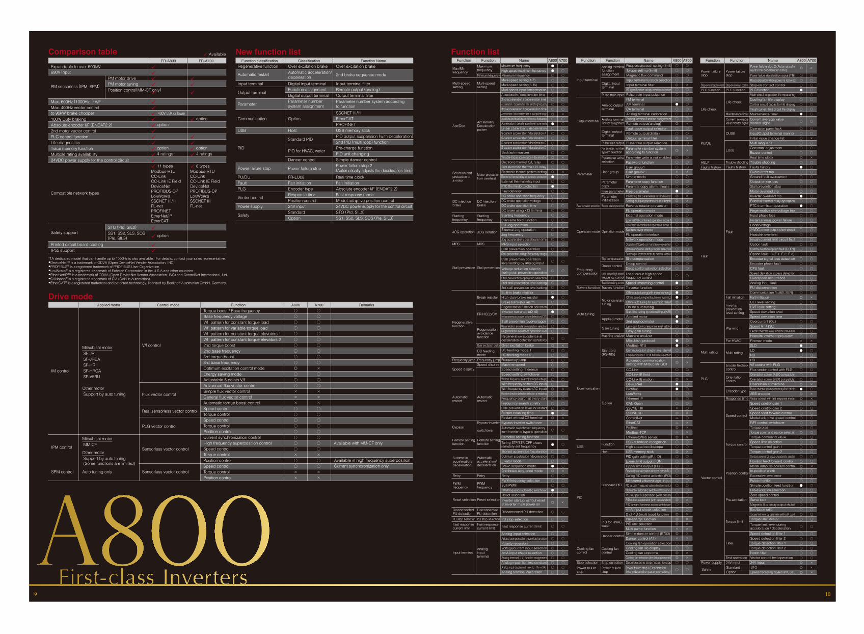
Comparison tableFR-A800 FR-A700
Expandable to over 500kW690V Input
PM sensorless (IPM, SPM)
Max. 600Hz (1000Hz*1) V/FMax. 400Hz vector controlto 90kW brake chopper100% Duty brakingAbsolute encoder I/F (ENDAT2.2)2nd motor vector controlPLC control functionLife diagnosticsTrace memory functionMultiple rating availability24VDC power supply for the control circuit
Compatible network types
Safety support
Printed circuit board coatingIP55 support
PM motor drivePM motor tuningPosition control(MM-CF only)
STO (Pld, SIL2)SS1, SS2, SLS, SOS(Ple, SIL3)
üüüüü
üüü 400V 55K or lowerüü option
üüüü option
ü 4 ratings
üü 11 typesModbus-RTUCC-LinkCC-Link IE FieldDeviceNetPROFIBUS-DPLONWORKSSSCNET III/HFL-netPROFINETEtherNet/IPEtherCAT
üü option
üü
üüü
ü option
üüü option
ü 4 ratings
ü 8 typesModbus-RTUCC-LinkCC-Link IE FieldDeviceNetPROFIBUS-DPLONWORKSSSCNET IIIFL-net
*1A dedicated model that can handle up to 1000Hz is also available. For details, contact your sales representative. •DeviceNet™ is a trademark of ODVA (Open DeviceNet Vender Association, INC).•PROFIBUS® is a registered trademark of PROFIBUS User Organization. •LONWORKS® is a registered trademark of Echelon Corporation in the U.S.A and other countries.•EtherNet/IP™ is a trademark of ODVA (Open DeviceNet Vender Association, INC) and ControlNet International, Ltd. •CANopen® is a registered trademark of CiA (CAN in Automation).•EtherCAT® is a registered trademark and patented technology, licensed by Beckhoff Automation GmbH, Germany.
ü:Available New function listFunction classification Classification Function Name
Over excitation brake
2nd brake sequence mode
Input terminal filterRemote output (analog)Output terminal filterParameter number system accordingto functionSSCNET III/HEtherCATPROFINETUSB memory stickPID output suspension (with deceleration)2nd PID (multi loop) functionPre-charge functionPID unit changingSimple dancer controlPower failure stop 2(Automatically adjusts the deceleration time)Real time clockFalt initiationAbsolute encoder I/F (ENDAT2.2)Fast response modeModel adaptive position control24VDC power supply for the control circuitSTO (Pld, SIL2)SS1, SS2, SLS, SOS (Ple, SIL3)
Automatic restart
Input terminal
Output terminal
Parameter
Communication
USB
PID
Power failure stop
PU/DUFaultPLG
Vector control
Power supply
Safety
Over excitation brakeAutomatic acceleration/decelerationDigital input terminalFunction assiqnmentDigital output terminalParameter numbersystem assiqnment
Option
Host
Standard PID
PID for HVAC, water
Dancer control
Power failure stop
FR-LU08Falt initiationEncoder typeResponse timePosition control24V inputStandardOption
Regenerative function
Drive modeApplied motor Control mode Function A800 A700 Remarks
Torque boost / Base frequencyBase frequency voltageV/f pattern for constant torque loadV/f pattern for variable torque loadV/f pattern for constant torque elevators 1V/f pattern for constant torque elevators 22nd torque boost2nd base frequency3rd torque boost3rd base frequencyOptimum excitation control modeEnergy saving modeAdjustable 5 points V/fAdvanced flux vector controlSimple flux vector controlGeneral flux vector controlAutomatic torque boost controlSpeed controlTorque controlSpeed controlTorque controlPosition control Current synchronization controlHigh frequency superposition controlSpeed controlTorque controlPosition control Speed controlTorque controlPosition control
○ ○○ ○○ ○○ ○○ ○○ ○○ ○○ ○○ ○○ ○◎○ ○○ ○○×××
×
××
×
× ×
× ×× ×
○
○ ○○ ○○ ○○ ○○ ○○ ○○ ○ Available with MM-CF only○ ○
○ ○ Available in high frequency superposition○ ○ Current synchoronization only
SPM control Auto tuning only
Sensorless vector control
Sensorless vector control
Mitsubishi motor MM-CF
Other motor Support by auto tuning (Some functions are limited)
IPM control
IM control
V/f control
Flux vector control
Real sensorless vector control
PLG vector control
Mitsubishi motor SF-JR SF-JRCA SF-HR SF-HRCA SF-V5RU
Other motor Support by auto tuning
Function Function Name A800 A700 Function Function Name A800 A700 Function Function Name A800 A700
Function listMaximumfrequencyMinimum frequency
Multi-speedsetting
Acceleratin/Decelerationpattern
Motor protectionfrom overheat
DC injectionbrake
Startingfrequency
JOG oeration
MRS
Stall prevention
Break resistor
FR-HC(2)/CV
Regenerationavoidancefunction
Over excitation brakeDC feedingmodeFrequency jumpSpeed display
Automaticrestart
Bypass-inverter
switchover
Remote settingfunction
Automaticacceleration/deceleration
Retry
PWMfrequency
Reset selection
DisconnectedPU detectionPU stop selectionFast responsecurrent limit
Analoginputterminal
Max/Minfrequency
Multi-speedsetting
Acc/Dec
Selection andprotection ofa motor
DC injectionbrake
Startingfrequency
JOG operation
MRS
Stall prevention
Regenerativefunction
Frequecny jump
Speed display
Automaticrestart
Bypass
Remote settingfunction
Automaticacceleration/deceleration
Retry
PWMfrequency
Reset selection
Disconnected PU detectionPU stop selectionFast responsecurrent limit
Input terminal
Maximum frequencyHigh speed maximum frequencyMinimum frequencyMulti-speed setting(1-7)Multi-speed setting(8-15)Multi-speed input compensationAcceleratin / deceleration time2nd acceleration / deceleration timeAcceleration / deceeleration time switching frequecny3rd acceleration / deceleration timeAcceleration / deceleration time in low-speed rangeAcceleration/deceleration reference frequencyAcceleration / deceleration time incrementsLinear cceleration / decelerationS-pattern acceleration / deceleration AS-pattern acceleration / deceleration BS-pattern acceleration / deceleration CS-pattern acceleration / deceleration DBacklash measuresVariable-torque acceleration / decelerationElectronic thermal O/L relay2nd electroinc thermal O/L relayElectronic thermal pattern settingElectronic thermal relay for transistor protectionExternal thermal relay inputPTC thermistor protectionFault definitionDC brake operation frequencyDC brake operation voltageDC brake operation timeDC brake using X13 terminalStarting frequencyStart-time hold functionPU Jog operationExternal Jog operationJog frequencyJog acceleration / deceleration timeMRS input selectionStall prevention operationStall prevention in high frequency rangeStall prevention operatiionlevel setting by analog inputVoltage reduction selectinduring stall prevention operationStall preveintion operation selection2nd stall prevention level setting3rd stall prevention level settingBuilt-in brake resistorHigh-dury brake resistorBrake transistor alarmRegenerative function selectionInverter run enable(X10)Instansaneous power failure detection(X11)Stall prevention (overvoltage)Regeneration avoidance operation selectionRegeneration avoidance operation levelRegeneration avoidance atdeceleration detection sensitivityOver excitation brakeDC feeding mode 1DC feeding mode 2Frequency jumpMachine speedSpeed setting referenceSpeed setting switchoverWithout frequency search(reduced voltage)With frequency search(DC input)With frequency search(AC input)Rotation direction detection selection at restartingFrequency search at every startFrequcncy search at retryStall prevention level for restartRestart coasting timeRestart without CS terminalBypass-inverter switchoverAutomatic switchover frequencyfrom inverter to bypass operationRemotoe setting functionTuring STF/STR OFF clearsremotely-set frequency
Reset selection
Shortest acceleration /decelerationOptimum acceleration / decelerationElvator modeBrake sequence mode2nd brake sequence modeRetryPWM frequency selectionSoft-PWMPWM frequency automatic switchover
Inverter startup without resetat inverter main power on
Disconnected PU detection
PU stop selection
Fast response current limit
Analog input selectionAdded compensation, override functionPolarity reversibleVoltage/current input selection4mA input check selectionAnalog terminal(1, 4) function assignmentAnalog input filter time constantAnalog input display unit selection (%<->V,A)Analog terminal calibration
○○○○○○○○○
○
○
○○○○●○○●○○○○
○
◎○○○○○○○○◎○○○○●◎○
○
○
●
○ ○○ ○○ ○● ○
×◎○ ○○ ○○ ○● ○○ ○
×◎
○ ○
○ ○
○ ○
○ ○○ ○○ ○○ ○○ ○○ ○○ ○○ ○○ ○
○○○○○○○○○
○
○
○○○○○○○○○○○○
○
×○○○○○○○○×○○○○○×○
○
○
○
● ○● ○○ ○○ ○○ ○○ ○○ ○○ ○○ ○○ ○
×◎○ ○● ○○ ○○ ○○ ○○ ○○ ○○ ○
×◎○ ○○ ○
×◎● ○○ ○● ○○ ○○ ○○ ○○ ○○ ○
PID
Output terminal
Input terminal
Parameter
Reverse rotation prevention
Operation mode
Frequencycompensation
Travers function
Auto tuning
Communication
USB
Cooling fancontrol
Stop selectionPower failurestop
Analog terminalfunctionassignment
Digital inputterminal
Pulse train input
Analog outputterminal
Analog terminalfunction assignment
Digital outputterminal
Pulse train outputParameter numbersystem selectionParameter writeselection
User group
ParametercopyFree parameterParameterinitializationReverse rotation prevention
Operation mode
Slip compensation
Droop control
Load torque high speedfrequency controlSpeed smoothing controlTravers function
Motor constanttuning
Applied motor
Gain tuning
Machine analizer
Standard (RS-485)
Option
Function
Host
Standard PID
PID for HVAC,water
Dancer control
Cooling fancontrol
Stop selectionPower failurestop
Frequency(speed) setting (limit)Torque setting (limit)Magnetic flux commandInput terminal function selectionInput terminal filterRT signal function validity condition selectionPulse train input selectionFM terminalAM terminalCA terminalAnalog terminal caribrationAnalog terminal function assignmentRemote output(analog)Fault code output selectionRemote output(disital)Output terminal filterPulse train output selectionParameter number systemaccording to functionParameter write is not enabledPassword functionUser group1User group2Simple modeParameter copy functionParamter copy alarm releaseFree parameterInitializing the parameters for IPM motorSetting multiple parameters as a batchReverse rotation preventionPU operation modeExternal operation modeExternal/PU combined operation mode 1External/PU combined operation mode 2Switch-over modePU operation interlockNetwork operation modeOperation / Speed command source selectionCommunication startup mode selectionSwitching of operation mode by external terminalSlip compensationDroop controlDroop control activation selectionLoad torque high speedfrequency controlSpeed smoothing controlTraverse functionOffline auto tuning(with motor running)Offline auto tuning(without motor running)Offline auto tuning for automatic restartOnline auto tuningStart-time tuning by external input(X28)Applied motor2nd applied motorEasy gain tuning response level settingEasy gain tuningMachine analizerMitsubishi protocolModbus-RTUCommunication check time intervalCommunication EEPROM write selectionAutomatic communicationsetting with Mitsubishi GOTCC-LinkCC-Link IE fieldCC-Link IE motionDeviceNetProfibusLonWorksEthernet IPCAN OpenSSCNET IIISSCNET/HControlNetEtherCATProfinetModbus-TCPEthernet(Web server)USB automatic recognitionHigh speed occiloscopeUSB memory stickPID gain setting(P, I, D)Lower limit output (FDN)Upper limit output (FUP)Forward (reverse) rotation direction output (RL)During PID control activated (PID)Measured valuevoltage input PID set point / measured value / deviation monitorPID control automatic switchover frequencyPID output suspension (with coast)PID output suspension (with deceleration)PID forward / reverse action switchover4mA input check selection2nd PID (multi loop) functionPre-charge functionPID unit selectionMulti pump functionSimple dancer control (E700)Dancer control (A1)Cooling fan operation selectionCooling fan life displayCooling fan stop timeCooling fan selection (for flat plate model)Decelerates to stop / coast to stopPower failure stop1 (Decelerationtime is depend on parameter setting)
○○○○◎○○○●○○○
◎○
○
◎○
○○○○×○○○○○○○×
○
○×
○
◎
○○○×○○○●◎◎○○○○○○○○○○○○○○
○
●○
×
○○○×○○○○××○○○○○○○○○○○○○○
○
○○○○×○○○○○○○○○○○
×
○○×○○○○○○×○××××
●●◎○○●●○○○●●○○
◎
○○◎●●○△○×◎△△◎△◎○○◎○○○○○○○○○◎○○◎◎◎×◎×○○◎◎○
○○×○○○○○○○○○×○○××××××○○××○
○ ○
Stop-on contact controlPLC function
Life check
PU/DU
Power failurestop
HELPFaults history
Fault
Multi rating
PLG
Vector control
Power supply
Safety
Stop-on contact controlPLC function
Life check
Maintenance timerCurrent averagevalue monitor signal
DU08
LU08
Power failurestop
Trouble shootingFaults history
Fault
Falt initiation
Inverterpreventionlevel setting
Warning
For HVAC
Multi rating
Encoder feedbackcontrol
Orientationcontrol
Encoder type
Response time
Speed control
Torque control
Position control
Pre-excitation
Torque limit
Filter
Test operation24V inputStandardOption
Stop-on contact controlPLC functionMain circuit capacitor life measuringCooling fan life displayControl circuit capacitor life displayInrush current limit circuit life displayMaintenance timerCurrent average valuemonitor signalOperation panel lockInput/Output terminal monitorInitial value change listMulti languageConstrast adjustmentBuzzer controlReal time clock
Power failure stop 2 (Automaticallyajusts the deceleration time)Power failure deceleration signal (Y46)Reacceleration when power is restored
Trouble shootingFaults historyOvercurrent tripGround fault overcurrentOutput phase lossStall prevention stopMotor overload tripInverter overload tripExternal thermal relay operationPTC thermistor operationRegenerative overvoltage tripInput phase lossInstantaneous power failureUndervoltage24VDC power output short circuitHeatsink overheatInrush current limit circuit faultOption faultCommunication option fault (E.OP1)Option fault1-3 (E.1, E.2, E.3)Encoder signal loss detectionEncoder phase faultCPU faultSpeed deviation excess detectionOverspeed occurrenceAnalog input faultPU disconnectionCommunication fault(E.SER)Falt initiationOLT level settingUVT level settingSpeed deviation levelSpeed deviation timeOvercurrent (OL)Speed limit (SL)Electric thermal relay function pre-alarmHeatsink overheat pre-alarmFireman modeSLDLDNDHDV/f control with PLGFlux vector control with PLGOrientation control (A500 compatible)Orientation control (V500 compatible)Orientation at machinePulse encoder (complementary/line driver)ABS encoderVector control with fast response modeSpeed control gain 1Speed control gain 2Speed feed forward controlModel adaptive speed controlP/PI control switchoverTorque biasTorque command source selectionTorque command valueSpeed limit selectionTorque control gain 1Torque control gain 2Constant power range torque characteristic selectionPosition feed forward controlModel adaptive position controlIn-position widthExcessive level errorPulse monitorSimple position feed functionPre-excitation selectionZero speed controlServo lockMagnetic flux decay output shutoffExcitation ratioTorque limit level by parameter setting (4 quad)Torque limit level 2Torque limit level duringacceleration / decelerationSpeed detection filter 1Speed detection filter 2Torque detection filter 1Torque detection filter 2Notch filterVector control test operation24V inputSTOSpeed monitoring, Speed limit, SIL3
○○○○○○○
○
○○×○○○×
○●○○○○●
○
○○○○○○◎
◎
○○
×
○○
○○○○○○○○○○○○○○○○○○○○○○○○○○○○×○○○○○○○○×○○○○○○○○×○×
○●○○○○○●○●○○○○○○○○○○○○○○○○○○◎○○○○○○○○×●●○○○○○○◎●◎
×○○○○○○○○○○○○○×○○○○○○○○○○○
○
○○○○○○×××
◎○○○○○○○○○○○○○◎○○○●○○○○○○○
○
○○○○○○◎◎◎
9 10