Embed Size (px)
Citation preview
FPGA REAL-TIME SIMULATION OF THE SQUIRREL CAGE INDUCTION GENERATORS USED FOR
CONVERSION OF RENEWABLES
Razvan Magureanu*, Bogdan Popa*, Horia Hedesiu**, Florin Hurdoi**
* University POLITEHNICA Bucharest, Splaiul. Independentei No 313, Bucharest, Romania, [email protected]
** National Instruments Romania, Bulevardul 21 Decembrie 1989, No. 77, Cluj Napoca, Romania, [email protected]
ABSTRACT: Electrical generators for Hydro or Aeolian energy conversion under 2 MW or smaller, coupled to the national grid are squarely cage induction machines. Smart or micro grids, with multiple generators and multiple variable loads, cannot be simulated in real time, using the existing commercial programs running on PCs, as these computers are not fast enough to allow also the observation of the state variables which cannot be measured and the estimation of the unknown parameters. In this paper a technique was developed based on parallel computation, on one or multiple FPGA boards operating in the same frame, programmed in Graphical LabView language from National Instruments.
Keywords: Induction Generators, Hydro and Wind Applications, Parallel Computation, FPGAs.
SIMULAREA ÎN TIMP REAL A GENERATOARELOR ASINCRONE CU ROTOR ÎN SCURT CIRCUIT UTILIZATE PENTRU CONVERSIA ENERGIILOR REGENERABILE – REZUMAT: Generatoarele electrice de puteri până la 2MW, legate la sistemul pentru conversia energiei eoliene sau hidraulice sunt de obicei maşini asincrone în scurt circuit. Simularea în timp real a unei asemenea micro reţele cu surse şi sarcini multiple cu un calculator PC oricât de performant ar fi, motiv pentru care se optează la computere cu procesare paralelă ceea ce evident este o soluţie scumpă. Progresele în ultimii ani în domeniul FPGA-urilor a făcut posibil acest tip de procesare într-un timp foarte scăzut încât simularea să fie chiar mai rapidă decât procesul real. În cazul de faţă simularea s-a făcut pe o platformă National Instruments şi programarea in limbajul LabView.
Cuvinte cheie: Generatoare Asincrone, Aplicatii Hidro si Eoliene, Calcule Paralele, FPGA.
1. INTRODUCTION
The electro mechanic dynamics of a power system depends of the mechanic and electric dynamics of every generator and every load, of transport system and every perturbation. It is clear, that the dynamics of a 1MW generator or of a 100KW load have very little effect on a 1GW group. Taking into account that the simulation model cannot contain all the sources and the loads some simplifications has to be applied function of powers and rated voltages. Function of the simulation software used and the power of the computers
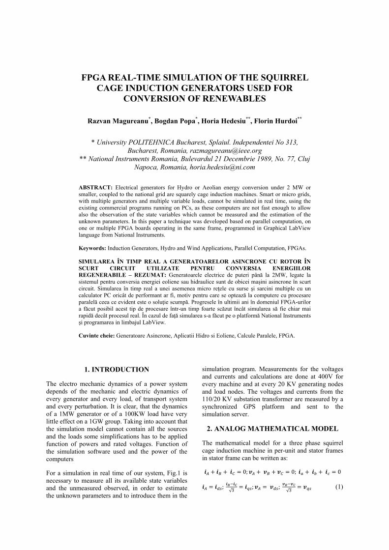
For a simulation in real time of our system, Fig.1 is necessary to measure all its available state variables and the unmeasured observed, in order to estimate the unknown parameters and to introduce them in the
simulation program. Measurements for the voltages and currents and calculations are done at 400V for every machine and at every 20 KV generating nodes and load nodes. The voltages and currents from the 110/20 KV substation transformer are measured by a synchronized GPS platform and sent to the simulation server.
2. ANALOG MATHEMATICAL MODEL
The mathematical model for a three phase squirrel cage induction machine in per-unit and stator frames in stator frame can be written as:
0; 0; 0
; √
; ; √
(1)
FPGA REAL-TIME SIMULATION OF THE SQUIRREL CAGE INDUCTION GENERATORS 223
; √3
; ;√3
(2)
0 ϣ ϣ
0 ϣ ϣ
where∙
, is the nominal pulsation, and
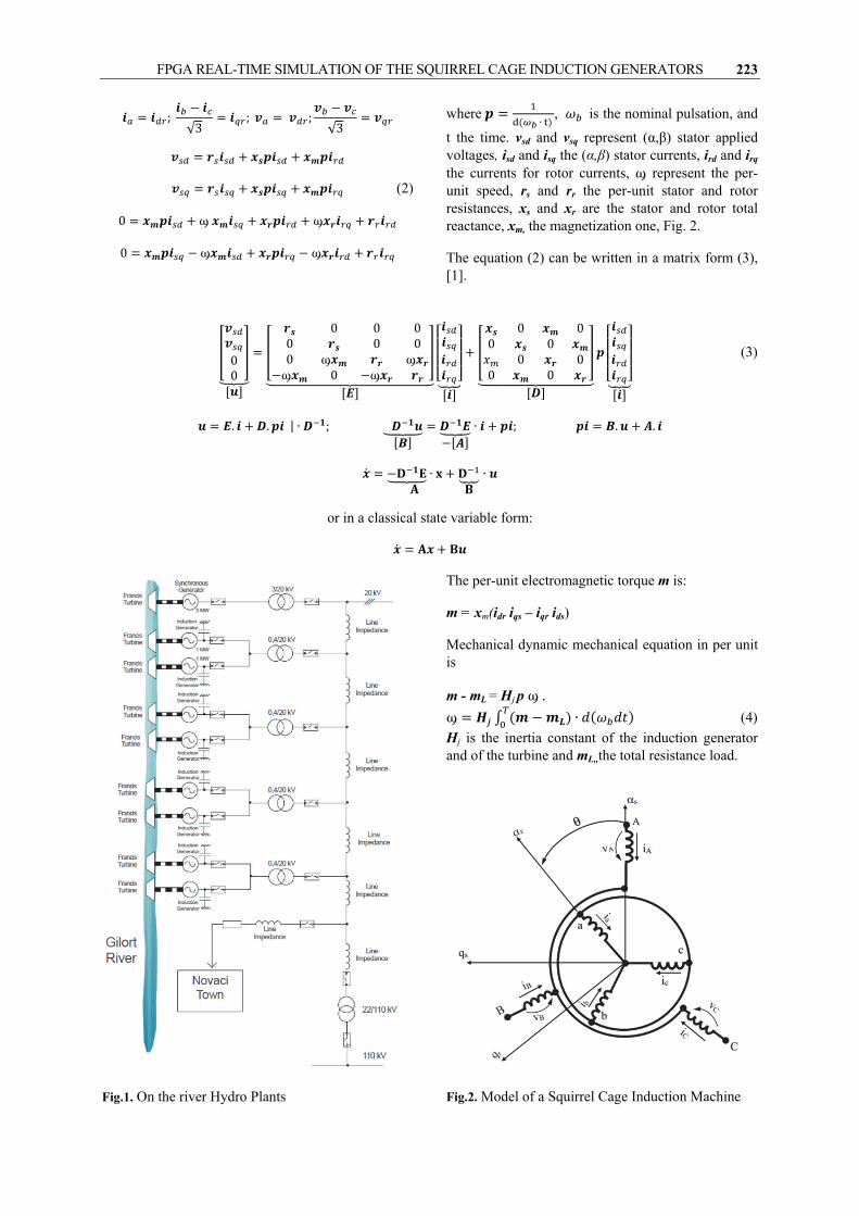
t the time. vsd and vsq represent (α,β) stator applied voltages, isd and isq the (α,β) stator currents, ird and irq the currents for rotor currents, ϣ represent the per-unit speed, rs and rr the per-unit stator and rotor resistances, xs and xr are the stator and rotor total reactance, xm, the magnetization one, Fig. 2.
The equation (2) can be written in a matrix form (3), [1].
00
0 0 00 0 00 ϣ ϣϣ 0 ϣ
0 00 0
0 00 0
(3)
. . | ∙ ; ∙ ; . .
∙ ∙
or in a classical state variable form:
Fig.1. On the river Hydro Plants
The per-unit electromagnetic torque m is:
m = xm(idr iqs – iqr ids)
Mechanical dynamic mechanical equation in per unit is
m - mL = Hj p ϣ. ϣ ∙ (4)
Hj is the inertia constant of the induction generator and of the turbine and mL,,the total resistance load.
Fig.2. Model of a Squirrel Cage Induction Machine

Lucrările celei de-a X-a ediţii a Conferinţei anuale a ASTR, 2015 224
3. DIGITAL MATHEMATIC MODEL
When we use a digital computer to simulate continuous systems the control signals, or the inputs are digitally sent at a constant frequency as a series of pulses of variable amplitude. Similarly the different states or outputs of continuous nature are transformed in digital form by an analog-to-digital converter (ADC) and by a zero-order-holder as a set of pulses of constant amplitude on a sample. As all the inputs and the perturbations are introduced also as similar pulses of constant amplitudes the resulted currents, the electromagnetic torque and the motor speed are imported to be calculated at the end of the each sample, Fig.3.
Such a system is called sampled system data, because some of purely continuous data are sampled before being used in calculations.
The time t is defined as multiples of periods of samples:
t1 = T , t2 = 2T , … tk = k T , tk+1 = (k +1)T
The stator voltages, in our case, are defined in these moments.
u(tk)= u(k T ) = u(k) = uk
The equations for an induction machine supplied by this kind of voltages, as in Fig.3 can be integrated, offline by classic methods as Euler, Runge-Kutta, Prediction-Corrector, which unfortunately are not fast enough for a real-time simulation.
In order to increase the speed of calculations in the case of a large power systems three solutions were available:
1. Using methods from theory of digital systems, [2].
2. Using advanced computers, parallel computation.
3. Using FPGAs and parallel computation, [3].
As for the time of a sample all the inputs and states can be considered constant, from initial moment of the pulse ti = kT to the final moment, tf = (k+1) T.
uti-tf = uk
Fig.3. Continuous and digitized input voltage
Noting: τ, γ τ
γ 1 ,γ 1
1! 2!⋯
!⋯
1! 2!⋯
!⋯
2! 3!⋯
1 !⋯
The integration of discreet mathematical model of the induction machines becomes:
1 (5)
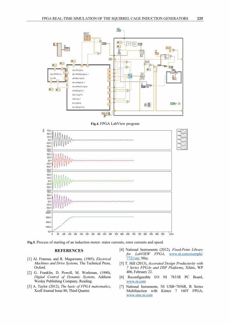
As an example for FPGA LabView program we used for simulation the starting of an AC induction motor is presented in Fig.4 and the results for stator and rotor currents in Amperes and the motor speed in radians/second, in Figure 5. The calculations were done Fixed-point mathematics and the simulation on a NI 7831R PC Board.
As the multiplication is more difficult to be done with FPGAs, we intend to use in the future a NI USB-7856R, Series Multifunction with Kintex -7 160T FPGA, with multiple DSP slices, [6], [7].
4. CONCLUSIONS
The above paper presented above is the first part for a more comprehensive work for a complete simulation of the network grid with 5 hydro plants, and 10 induction generators, from Fig.1. Next step for our simulation program will be to take into account that every induction generator operate in parallel with a bank of capacitors in order to improve their power factor. Consequently four more variables will be added and the total model is represented by an 8x8 matrix and for the entire generating grid with 10 generators by 80x80 one, and the simulation model has to contain 10 building blocks connected in a common grid.
Advanced FPGAs chips also have DSPs for simpli-fication of the design and accelerate the calculations property which will be used in more complex systems.
FPGA REAL-TIME SIMULATION OF THE SQUIRREL CAGE INDUCTION GENERATORS 225
Fig.4. FPGA LabView program
Fig.5. Process of starting of an induction motor: stator currents, rotor currents and speed
REFERENCES
[1] Al. Fransua, and R. Magureanu, (1985), Electrical Machines and Drive Systems, The Technical Press, Oxford.
[2] G. Franklin, D. Powell, M. Workman, (1990), Digital Control of Dynamic Systems, Addison Weslay Publishing Company, Reading.
[3] A. Taylor (2012), The basic of FPGA matrematics, Xcell Journal Issue 80, Third Quarter.
[4] National Instruments (2012), Fixed-Point Library for LabVIEW FPGA, www.ni.com/exemple/ 7721/en/, May.
[5] T. Hill (2013), Accerated Design Productuvity with 7 Series FPGAs and DSP Platforms, Xilinx, WP 406, February 22.
[6] Reconfigurable I/O NI 7831R PC Board, www.ni.com
[7] National Insruments, NI USB=7856R, R Series Multifunction with Kintex 7 160T FPGA, www.sine.ni.com

![Meaning of Nameplate [Gear + AC Squirrel Cage Motor ...€¦ · 1. Prepared this document byNapawanPachongharn Meaning of Nameplate [Gear + AC Squirrel Cage Motor] 2 ตัวอย่างเนมเพลทของ](https://img.dokumen.tips/doc/110x75/5fc76ea435059622f15853c3/meaning-of-nameplate-gear-ac-squirrel-cage-motor-1-prepared-this-document.jpg)

![Combined Field and Circuit Theories in Squirrel-Cage ...research.engineering.nyu.edu/power/sites/engineering.nyu.edu.power/... · induction pumps and generators [7], and armature](https://img.dokumen.tips/doc/110x75/60b764658a7bbc4baa1d6f13/combined-field-and-circuit-theories-in-squirrel-cage-induction-pumps-and-generators.jpg)