Embed Size (px)
Citation preview

PEDS 2007
FPGA Implementation of Quasi-BLDG DriveC.S. Soh 2, C. Bi 2, and K.K. Teo'
'Data Storage Insitute, 5 Engineering Drive 1, Singapore 1176082National University of Singapore, ECE, 4 Engineering Drive 3, Singapore 117576
Abstract-For the reduction of acoustic noise andvibration generated in self-sensing brushless dc motoroperation, a self-sensing quasi brushless DC drive (QBLDC)mode is presented. The structure of the drive and therelated algorithms are introduced in detail in the paper. Thedrive can be implemented on field programmable gatearrays (FPGA). The performance of the drive presented hasbeen confirmed by the testing results of the spindle motorused in hard disk drive.
Index Terms-Self-sensing, BLDC, Spindle Motor,Acoustics and FPGA.
I. INTRODUCTION
The introduction of high energy permanent magnetmaterials coupled with the increasing concerns for powerefficiency has opened the gateway for Permanent MagnetSynchronous Motor (PMSM). The benefits of usingPMSM include power density and high efficiency andlow acoustics noise. As such, it has become an attractiveoption for industrial applications, such as Hard DiskDrives (HDD). The motor deployed HDD are a subcategory belonging to PMSM, commonly known asBrushless DC Motor (BLDCM). Compared to PMSMs,this kind of BLDCM has several unique features. Therotor of BLDCMs has got surface-mounted permanentmagnet constructing a smooth-air-gap machine. As such,reluctance torque contributed by inductance variationscan be neglected. In addition, the rotor utilizes fractional-slots which in turn make the cogging torque negligible.These, together with other features, such as sinusoidal!trapezoidal back-emfs and a well symmetrized three-phase structure, create an unique PMSM or a BLDCM. 1
In PMSM drives, the motor usually has a rotorposition sensor, such as encoder or resolver. In BLDCMdrive, usually three hall effect sensors are used as rotorposition sensors. However, these sensors are undesirableas they incur additional cost and space. As such, self-sensing, or sensorless control, is often being deployed forthe BLDCM drives. There are many categories of self-sensing solutions [1]-[3], such as the back-EMF voltagesensing, back-EMF integration, flux estimation anddetection of freewheeling diodes conduction. In HDD,the self-sensing operation is accomplished by theutilizing the back-EMF zero crossing points (ZCPs) asrotor position information. In a BLDC drive, each gateturns on for 1200 and for each phase, there will be twosilent periods, each of 600, where the terminals arefloating. It is during the silent phase that the ZCPs will
This work was supported by Data Storage Institute, Singapore
occur and to detect these ZCPs, a common method is tocreate a virtual neutral point and compare it to the voltageterminal. And the resulting signal will have ZCPsequivalent to the back-emf ZCPs. However, due to gatecommutation, spikes occur and these will result in falseZCPs.
Back-emf based methods, however, fail during startingwhere the back-emf are zero or small. As such, duringstarting, the motor is driven open loop with six-steppingon a skewed frequency to a speed, (o, At co, the back-emf is sufficiently large to be detected and all voltageterminals are floated for back-emf detection. However,due to the removal of gating signals, the motor will bedecelerating and this will result in declining back-emfs.Thus, in the determination of co, it is tuned higher totake into account of this decline. Beyond wo,, the systemadvances to the self-sensing BLDC drive.
In BLDC drive, during the 1200 conduction segment,the goal is to inject rectangular stator phasor currentsduring that period. However, the motor being inductive,voltage spikes will occur during commutation. Thesespikes are undesirable as they are a source of bothelectrical and mechanical noise, and vibration.
In recent years, owing to the progress of VLSItechnology, the field programmable gate array (FPGA)has gained world wide acceptance. It has traditionallybeen perceived as a essential platform for ApplicationSpecific Integrated Circuit (ASIC) prototyping.However, in recent years, it has gained significant marketshare in end-product solutions as fundamentally, FPGAoffers fast time to market, low design/manufacturing costand risk, extremely high processing performance, andprogrammability.
The research goal of this paper is to design a Self-Sensing Quasi-BLDC (QBLDC) Drive on FPGA. TheFPGA design comprises of(1) an innovative back-emf based method for rotor
position detection with zero delay;(2) a six step 6' masked open loop starting for bumpless
crossover to BDLC/QBLDC drive, and(3) a QBLDC drive for reduction of acoustics and
vibration generated in the motor operation.In (1), the proposed method takes an integrative
approach in back-emf zero-crossing-points (ZCP)detection and BLDC/QBLDC drive implementation.Heuristic logic is adopted in the implementation andaccurate BDLC/QBLDC drive with zero delay ZCPdetection for wide speed range is achieved. In (2), theproposed methodology proposes a novel gate signalmasking on a six step open loop self starting enabling
1-4244-0645-5/07/$20.00©2007 IEEE 883Authorized licensed use limited to: University of Shanghai For Science and Technology. Downloaded on July 13,2020 at 12:04:28 UTC from IEEE Xplore. Restrictions apply.
back-emf detection possible without a complete removalof gating signals. The strategy offers the advantages of i.an earliest possible crossover while making noassumption on the crossover frequency, ii. smoothcrossover as the motor rotation is continued iii.continuance of frequency skewing during detection. In(3), the proposed drive aims to reduce the drive acousticsand runout by the reduction of the drive current spikes. Ituses a trapezoidal drive instead of rectangular drive forgating. By utilizing such an approach, the current spikesare reduced and its effect on acoustics and vibration arereduced.
II. BRUSHLESS DC (BLDC) OPERATIONIn a BLDC drive, the motor is typically driven by a
three-phase inverter circuit as shown in Fig. 1. It consistsof six power semiconductor transistors with a protectiondiode connected in parallel to each of these transistors.
III. SELF-SENSING OPERATION USING BACK-EMF ZCPDETECTION
As highlighted, during the unexcited phase, the phasevoltage gives the phase back-emf which wouldencompass the ZCP. In the detection of ZCP, however,the entire phase voltage is not required as at the instantsof ZCPs, the terminal voltages would be equal to theneutral voltage. Consequently, the detection of ZCPs isequivalent to the detection of the instants whereby VANor VBN or VCN equals to zero. Whilst the terminalvoltages are available, the neutral voltage might not beavailable. A common method is to reconstruct a "virtual"neutral which provides a equivalence to the actualneutral. To derive the ZCP signals, the terminal voltageis thus compared to the virtual neutral voltage and thecomparison will provide signals with ZCPscorresponding to the back-emf ZCPs. Fig. 3 illustratesthe notion pictorially depicting the terminal voltagescomparison with the virtual neutral constructed.
Fig. 1. Bridge Circuit for BLDC Drive
Each transistor is gated by a 120°-conduction drive, inwhich each gate turns on for 120 electrical degrees ineach cycle. Commutation occurs at every 60 electricaldegrees of rotation in the sequence QAH, QCL, QBH,QAL, QCH and QBL. For maximum torque production,the gating with respect to the back-emf is given in Fig. 2.For each phase, there will be two unexcited 600 periods,where the voltage terminals are floating or unexcited.During this unexcited phase, the phase voltage gives thephase back-emf. Optimally, the zero crossing points(ZCPs) of the phase back-emfs should occur mid-way inthe silent period. These ZCPs represent positioninformation and it's based on this that self-sensingoperation using back-emfZCP detection is established.
'VA
'VB
Fig. 2. Terminal Voltage waveforms
Fig. 3. ZCP Detection Circuit
Practically, however, the simplistic topology fail asvoltage spikes will occur for every commutation. As aresult, false ZCPs are immersed amongst true ZCPs. Thisproblem has been well documented and researched,among which many methods center on the usage of filterswhich inevitably result in phase delays.
/,, / '\-{\N \:0NA
Fig. 4. Comparator Waveforms
884Authorized licensed use limited to: University of Shanghai For Science and Technology. Downloaded on July 13,2020 at 12:04:28 UTC from IEEE Xplore. Restrictions apply.

Most of the methods focus on the removal or exclusionof these false ZCPs when they occur. In this proposedmethod, an adoption of an integrative Zero Delay ZCPDetection - BLDC drive is utilized.
In a BLDC drive, a commutation occurs 30 electricaldegrees (300) after every true ZCP is detected. Toestimate this 300, the following algorithm is proposed.a. A global free running counter is implemented in the
design and latches are used to store the counter countsfor all the ZCPs.
b. Positive edge transitions will be used to latch the 00,1200 and 2400 ZCPs counter counts whereas negativeedge transitions will be used to latch the 600, 1800 and3000 ZCPs counter counts.
c. 300 time lag is to be estimated using the 600 time lapsefrom the last ZCP to latest ZCP detected. Forexample, to estimate the 300 time lag after theoccurrence of 00 ZCP, the 300 time lag would beequivalent to the point whereby the counter has furtherincreased by 1/2 x (LatchO° - Latch300°) since the 00ZCP. The factor of 1/2 is easily accomplished by asingle bit right shift of (LatchO° - Latch300°).At this juncture, the algorithm, however, too suffers
from the presence of false ZCPs, resulting in incorrectcounter counts being latched. However, achieving zerodelay ZCP detection is only possible if all ZCPs are takenas true as when it occurs. This constraint implies that thelatching must be done for all ZCPs, true or false.
This constraint can be elegantly respected by theinclusion of false ZCP avoidance within the BLDC drivealgorithm. An unique property derived from the signalsis during the 300 time lag for commutation, after anactive ZCP detection, inactive ZCPs should never occurduring the 300 time lag. For example, 00 ZCP countercount will be latched by positive or rising edge ZCPtransitions. However, in the 300 time lag, inactivenegative or falling edge ZCP will not occur if thepreceding active ZCP is true. Hence, in the presence ofan inactive ZCP during the 300 time lag interval, theinterval will be made inactive, latch will be restored to itsprevious count and active edge ZCP transition is awaited.As an additional level of heuristic control, it can beobserved that apart from satisfying the 300 time lag,commutation should occur only at the active level. Thus,the integrated algorithm becomesa. A global free running counter is implemented in the
design and latches are used to store the counter countsfor all the ZCPs.
b. Positive edge transitions will be used to latch the 00,1200 and 2400 ZCPs counter counts whereas negativeedge transitions will be used to latch the 600, 1800 and3000 ZCPs counter counts. 300 time lag is to beestimated using the 600 time lapse from the last ZCPto latest ZCP detected.
c. Occurrence of inactive edge transitions will be resetZCP counter counts to its previous counter values.Negative edge transitions will trigger a reset of the 00,1200 and 2400 ZCPs counter counts whereas positive
edge transitions will trigger a reset of the 600, 1800and 3000 ZCPs counter counts.
d. If the current count minus the ZCP latched countequals to the estimated 300 time lag and current ZCPsignal level remains active, commutation occurs.Waiting for 600 ZCP counter counts commences.
e. Pictorially, the algorithm is provided in Fig. 5 and itsschematic provided in Fig. 6.
Fig. 5. Flowchart of proposed algorithm
Fig. 6. Schematic of integrated Zero Delay ZCP Detection
IV. CROSSOVER FROM SIX STEPPING TO SELF-SENSINGBLDC OPERATION
In self-sensing bldc operation, position feedback fromback-emf ZCPs is not available at starting or low speeds.The motor is typically open loop started from standstill ina six stepping mode with a skewed frequency to eCOspeed. At wco, two conditions must be met; (i) back-emfis sufficiently large to be detected (ii) ZCPs occur duringthe unexcited phase of gating. Fig. 7 gives the gatingsignals with respect to the ZCP signals in an idealcrossover.
Fig. 7. Gating & Back-Emf Waveforms
885Authorized licensed use limited to: University of Shanghai For Science and Technology. Downloaded on July 13,2020 at 12:04:28 UTC from IEEE Xplore. Restrictions apply.

However, practically, it is tuned to achieve the gatingand ZCP phasor relationship as in Fig. 7. Such anapproach, apart from requiring time and effort, is systemdependent. Another approach is to switch off all thegates and detect the ZCPs as soon as the phase currentsdecrease to zero. This method, though simplistic, causesthe motor to decelerate and its corresponding back-emf todiminish which inevitably requires a higher co,Furthermore, the deceleration of the motor will cause a"bump" in the crossover. In addition, in the event of afailure, restarting is difficult as it is to be restarted on adecelerating motor.
In this proposed methodology, a novel gate signalmasking technique is utilized, making back-emf detectionpossible without a complete removal of gating signals.To provide insights into this, it would be beneficial if thephenomenon at six stepping is better understood. Duringopen loop six stepping, generally, the wave will not bethat as intended. Typically, the drive is over driven toprovide a higher starting torque for acceleration as well asovercoming frictional, viscous torque. The phasorrelationship between the gating and backemf will differby a larger angle than that seen in Fig. 7. Generally, in anextreme case, the phasor relation is similar to thatillustrated in Fig. 8.
Fig. 8. Gating & Back-Emf Waveforms
As mentioned, to extract the ZCPs, the system can betuned or all the gates turned off. In this method, thismatter can be elegantly rectified by performing gatemasking.
The motor is similarly started on a six-stepping mode.However, the gating signals are masked out an arbitraryangle, 6, as soon as the motor rotates. This will increasethe silent phase window and for any 6 > 600 this willguarantee at least one ZCP detection. Fig. 9 illustratesthe possible detection of a ZCP with gate signalsmasking.
In doing so, since only 600 of the gating signals aremasked out, the inertia of the motor will keep rotationgoing in contrast with the complete removal of gatingsignals. This means even if the window/back-emf ismissed, the same back-emf amplitude is available fordetection after a 3000 angle rotation. Thus, since themotor is not made to decelerate, a smooth and morerobust transfer is possible. In addition, the assumptionthat the back-emf is large enough for detection is nolonger necessary as such strategy allows the skewing offrequency to be continued till back-emf is large enoughfor ZCP to be detected.An extension of the method is to mask the gating
signals by 6= 1200. In doing so, an additional 600 windowwill make two ZCPs available for detection. This willgreatly reduce the possibility of erroneous detection sincedual detection is provided. However, it must be notedthat, by setting up gate masking, the starting torque willbe reduced. Nevertheless, it should not be a concern asthe motor is commonly overdriven at starting.
V. SELF-SENSING QUASI-BLDC (QBLDC) OPERATIONIn BLDC operation, for torque production, the
transistors are commutationally switched as shown in Fig.10 to provide rectangular stator currents. While theobjective is to inject phasor rectangular currents, inreality, current waveforms as shown in Fig. 11 areinjected. The reason being, the motor is inductive innature will accumulate energy when driven. Duringcommutation, the interruption of inductive currents willresult in current spikes. There are two types of spikesbelonging to two different sources. For those spikes atthe side (in-phase spikes), they are to the turning on andoff of its corresponding gates, whereas for the spikes atthe middle of the rectangular currents (adjacent-phasespikes), they are due to the turning on and off of itsadjacent gates. Nevertheless, both of these spikes areundesirable as they are a source of noise and vibration.
oJAL
QJJhT
Fig. 9. Gating & Back-Emf Waveforms with 6 masking, 6 = 60°
Fig. 10. BLDC Gating Signals
886Authorized licensed use limited to: University of Shanghai For Science and Technology. Downloaded on July 13,2020 at 12:04:28 UTC from IEEE Xplore. Restrictions apply.

Therefore, to turn off QAH, the NOT of QBH is applied.In doing so, at any one time, only one gate from the upperleg is turned on. This will ensure that the currentfollowing through QCL remains relatively constant andalso the currents through QAH and QBH are respectivelydecreasing and increasing slowly.In self-sensing bldcoperation, position feedback from back-emf ZCPs is notavailable at starting or low speeds. The motor is typicallyopen loop started.
Fig. 11. BLDC Phase Currents
To reduce these spikes a quasi-BLDC drive isproposed. In this drive, trapezoidal phase voltages asshown in Fig. 12 are to be achieved instead of rectangularphase voltages. Execution wise, it means to compare atrapezoidal reference to a triangular signal.
VAN
Fig. 12. QBLDC Phase Voltages
The purpose of such a drive is to control the injectionand withdrawal of phase currents to reduce the in-phasespikes. On a single phasor topology, it works fine andthese spikes can be significantly reduced. However, in athree phase topology, such a method gives rise to apeculiar development. The in-phase spikes will reducebut adjacent-phase spikes will increase. In-phase spikescan be reduced as voltages are slowly injected. However,due to a three phase topology, the overlap in gatingbetween the commutating phases will result in anincreased current in the non-commutating phase. Thisnon-commutating phase, then, suffers from adjacent-phase spikes. This is illustrated in
Fig. 13 under (I). In the turning off of phase A andturning on of phase B, there will be instants where bothQAH and QBH are turned on. This implies a spike incurrent in phase C.
To deal with this problem, the PWM trapezoidalswitching in (II) is proposed. In this proposed switching,to turn on a gate, the trapezoidal reference and the normalPWM is used. However, to turn it off, the logic inverseof the adjacent sequential gating signal is used. Forexample, QBH is turned on following QAH is turned off.
QIH~~~~I
QBH
0OgH' P SVM
Original PWM Signal
QAm (II)
(0AH*PVfVhM
OBH
PpBoH eP W Sn
Proposed PWMs Signal
Fig. 13. PWM Signals for QBLDC Drive
VI. FPGA IMPLEMENTATION AND EXPERIMENTALRESULTS
The overview of the FPGA implementation isprovided in Fig. 14. Each of the modules have beencoded with VHDL and is implemented on a XC4VFX12,a Xilinx Virtex-4 FX FPGA Device. The design issynthesized, implemented and simulated entirely onXilinx ISE 8.1. The design was then used to drive a HardDisk Spindle.
Fig. 14. Block Diagram ofFPGA Design
Fig. 15 gives the terminal voltage waveform VA, thevirtual neutral VN, the ZCP waveform from a comparatorand IA, the phase current. It can be observed that falseZCP are not treated as true and the true ZCP are in factused for commutation.
887
-IA -
'B
'C
I-
|Six-Step |_
|Self Start | ,
CrossoverII
B LDC _ X.Cm..
Authorized licensed use limited to: University of Shanghai For Science and Technology. Downloaded on July 13,2020 at 12:04:28 UTC from IEEE Xplore. Restrictions apply.
I.
3-+
Fig. 15. Waveforms for BLDC Drive
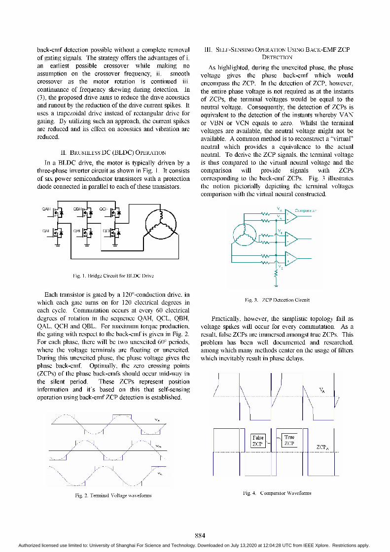
In the implementation of QBLDC, the BLDC entityis swapped with QBLDC. The current waveformcomparison between the two drives are given in Fig. 16.
IVN4aH 1. hI4.
Fig. 16. Current Waveforms for BLDC & QBLDC Drive
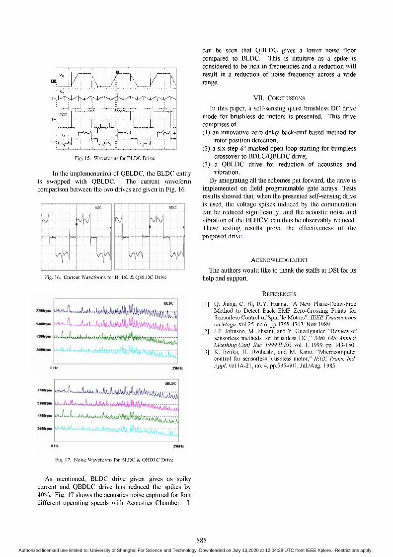
can be seen that QBLDC gives a lower noise floorcompared to BLDC. This is intuitive as a spike isconsidered to be rich in frequencies and a reduction willresult in a reduction of noise frequency across a widerange.
VII. CONCLUSIONSIn this paper, a self-sensing quasi brushless DC drive
mode for brushless dc motors is presented. This drivecomprises of(1) an innovative zero delay back-emf based method for
rotor position detection;(2) a six step 6' masked open loop starting for bumpless
crossover to BDLC/QBLDC drive;(3) a QBLDC drive for reduction of acoustics and
vibration.By integrating all the schemes put forward, the drive is
implemented on field programmable gate arrays. Testsresults showed that, when the presented self-sensing driveis used, the voltage spikes induced by the commutationcan be reduced significantly, and the acoustic noise andvibration of the BLDCM can thus be observably reduced.These testing results prove the effectiveness of theproposed drive.
ACKNOWLEDGEMENT
The authors would like to thank the staffs at DSI for itshelp and support.
OLD
aHZ
REFERENCES
[1] Q. Jiang, C. Bi, R.Y. Huang, "A New Phase-Delay-FreeMethod to Detect Back EMF Zero-Crossing Points forSensorless Control of Spindle Motors", IEEE TransactionsonMagn, vol 25, no 6, pp 4358-4363, Nov 1989.
[2] J.P. Johnson, M. Ehsani, and Y. Guzelgunler, "Review ofsensorless methods for brushless DC," 34th IAS AnnualMeething Conf Rec. 1999 IEEE, vol. 1, 1999, pp. 143-150
[3] K. lizuka, H. Uzuhashi, and M. Kano, "Microcomputercontrol for sensorless brushless motor," IEEE Trans. IndAppl. vol IA-21, no. 4, pp.595-601, Jul./Aug. 1985
S4@rpm
gm~t
Fig. 17. Noise Waveforms for BLDC & QBDLC Drive
As mentioned, BLDC drive given gives as spikycurrent and QBDLC drive has reduced the spikes by40%0. Fig. 17 shows the acoustics noise captured for fourdifferent operating speeds with Acoustics Chamber. It
888
... ....
~~~~~n.~~~~~~.-..---..1... ..IA
-....'. .''t '''.< ' .---- -- --...................................I..............~~~~~~~~~~~~~~~
2- X
no%** LM
i.
ooeqm
254dii
OBLIDC
iiiow ~
Authorized licensed use limited to: University of Shanghai For Science and Technology. Downloaded on July 13,2020 at 12:04:28 UTC from IEEE Xplore. Restrictions apply.