Embed Size (px)
Citation preview
Progress In Electromagnetics Research C, Vol. 35, 35–48, 2013
FPGA IMPLEMENTATION OF SPACE-TIME ADAPTIVEPROCESSING (STAP) ALGORITHM FOR TARGETDETECTION IN PASSIVE RADARS
Zia Ul Mahmood1, *, Mubashir Alam1, Khalid Jamil2, andZeyad O. Al-Hekail1, 2
1Department of Electrical Engineering, King Saud University, Riyadh,Saudi Arabia2Prince Sultan Advanced Technologies Research Institute, King SaudUniversity, Riyadh, Saudi Arabia
Abstract—Space-Time Adaptive Processing (STAP) algorithm hasrecently been used in Passive Bi-static Radars (PBR) because itremoves the clutter and non-cooperative transmitter effectively makingthe target detection easy in harsh environments like air-ground. Real-time implementation of STAP is a very challenging task as it iscomputationally-intensive, time-critical and resource-hungry process.This paper focuses on the Field-Programmable Gate Array (FPGA)implementation of STAP algorithm for passive radar using FM radioas transmitter of opportunity. The signals of interest were collectedusing an eight-channel software-defined radar with a uniform circulararray (UCA). The STAP processing was simulated using MATLAB andhardware implementation was carried out on a Xilinx Virtex-6 FPGA.The system is tested using experimental radar data. Timing and Poweranalysis of hardware implementation justifies that FPGA provides afast and reliable platform for STAP real-time radar processing.
1. INTRODUCTION
Passive bi-static radars (PBR) has received significant interest duringthe past few years among various defense entities for surveillance anddefense applications. These radars exploit signals of opportunity froma wide variety of communication or broadcast emissions like FM,TV, GSM, DAB, DVB-T, WiMax, WLAN/WiFi, satellite, etc. [12–18, 24]. They offer a number of advantages over conventional active
Received 10 October 2012, Accepted 29 November 2012, Scheduled 30 November 2012* Corresponding author: Zia Ul Mahmood ([email protected]).
36 Mahmood et al.
radar system: reduced operational cost, lower power requirements,covertness and anti-stealth.
A typical passive radar system consist of two channels connectedwith two antennas. One antenna, labeled as reference antenna,captures the direct (reference) signal from the transmitter. A secondantenna captures the reflected signal from target. These two signalsare processed together for target detection using match-filtering likecross-ambiguity processing [8, 9, 16, 23].
A more sophisticated multi-channel multi-frequency digitalreceiver system is developed using an array of antennas [19]. Thistype of advance system gives additional capabilities like digitalbeamforming and advance adaptive filtering for target detection andclutter rejection [9, 19, 20]. One of the candidate adaptive algorithmfor this kind of radar processing is joint space-time adaptive processing(STAP). It is particularly useful in detecting weak and slow movingground targets in airborne clutter environments.
Much of the research has been done on STAP with active radarsusing uniform linear array (ULA) [3, 10, 11] and circular array [4, 5, 7].Some of the research exists on the clutter suppression of airborneradar [25–27]. Similarly, some adaptive filter algorithms were usedfor clutter cancellation in PBR [22]. A code was designed to maximizethe detection performance of radar STAP [21]. A limited researchexists on using STAP for a passive radar system. One such systemand algorithm is presented in [8, 9], which uses a receiver setup of twoantenna system to capture the signal of interests. Further research wasconducted in an attempt to develop a more advanced receiver setup likeULA [1, 2] and UCA [6, 19, 20]. There is no notable research availableon the FPGA implementation of STAP algorithm for PBR case whileusing UCA for effective target detection and tracking.
This paper presents modeling and implementation of STAPalgorithm for target detection in passive bistatic radar case using auniform circular array to capture the signals of interest. The antennaarray consists of eight elements with uniform radial spacing. The UCAgeometry is deployed due to its ability to steer the beam in azimuthdigitally through 360◦ without any mechanical movement [6]. Also, acooperative FM transmitter was used as an illuminator of opportunity.The actual experiment was performed with moving vehicle as a target.
This paper emphasizes the hardware implementation aspect ofSTAP algorithm in PBR. System model containing the data receptionscenario and the pre-processing steps are explained in Section 2. Theprocessing results are described in Section 3. Section 4 explains theFPGA implementation of the STAP processor. Concluding remarksare given in Section 5.
Progress In Electromagnetics Research C, Vol. 35, 2013 37
2. DATA RECEPTION SCENARIO
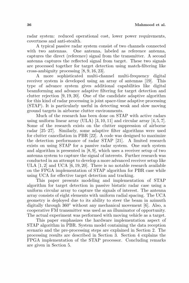
The experimental setup consists of an FM transmitter, a movingvehicle as a target and a circular eight-element antenna array as shownin Fig. 1. This is used to record the eight real time signals separatelyimpinging on each antenna element of the uniform circular array.
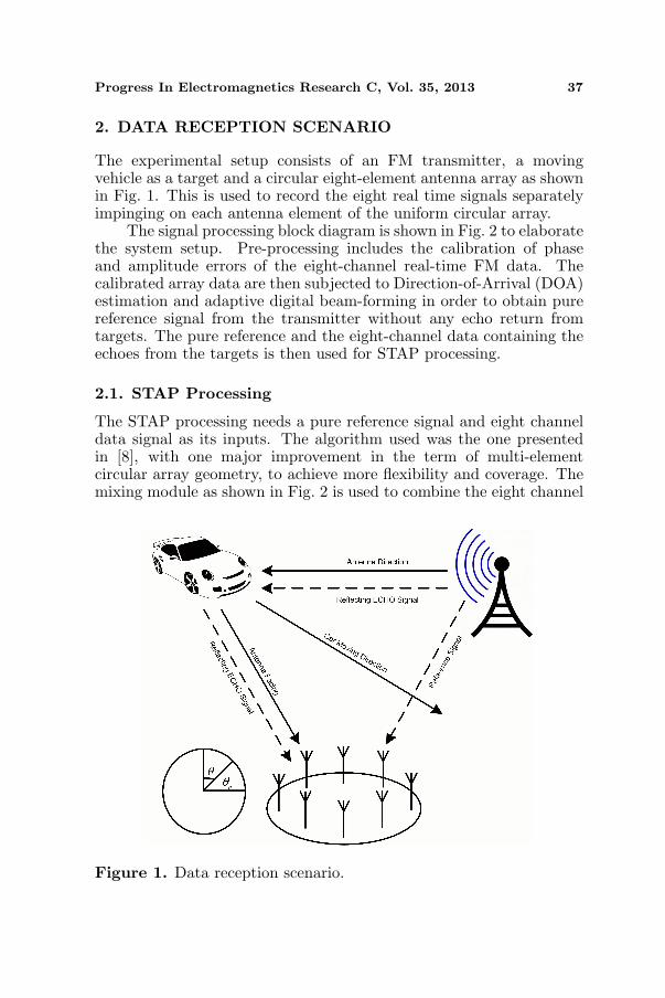
The signal processing block diagram is shown in Fig. 2 to elaboratethe system setup. Pre-processing includes the calibration of phaseand amplitude errors of the eight-channel real-time FM data. Thecalibrated array data are then subjected to Direction-of-Arrival (DOA)estimation and adaptive digital beam-forming in order to obtain purereference signal from the transmitter without any echo return fromtargets. The pure reference and the eight-channel data containing theechoes from the targets is then used for STAP processing.
2.1. STAP Processing
The STAP processing needs a pure reference signal and eight channeldata signal as its inputs. The algorithm used was the one presentedin [8], with one major improvement in the term of multi-elementcircular array geometry, to achieve more flexibility and coverage. Themixing module as shown in Fig. 2 is used to combine the eight channel
Figure 1. Data reception scenario.
38 Mahmood et al.
Figure 2. Signal processing block diagram of an array based passiveradar.
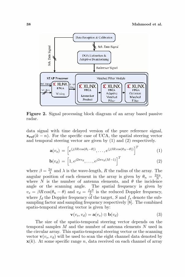
data signal with time delayed version of the pure reference signal,xref (k − n). For the specific case of UCA, the spatial steering vectorand temporal steering vector are given by (1) and (2) respectively.
a(vs) =[e(jβR cos(θ1−θ)), . . . , e(jβR cos(θN−θ))
]T(1)
b(vd) =[1, ej2πvd , . . . , ej2πvd(M−1)
]T(2)
where β = 2πλ and λ is the wave-length, R the radius of the array. The
angular position of each element in the array is given by θn = 2πnN ,
where N is the number of antenna elements, and θ the incidenceangle or the scanning angle. The spatial frequency is given byvs = βR cos(θn − θ) and vd = fdS
fsis the reduced Doppler frequency,
where fd the Doppler frequency of the target, S and fs denote the sub-sampling factor and sampling frequency respectively [8]. The combinedspatio-temporal steering vector is given by:
v(vs, vd) = a(vs)⊗ b(vd) (3)
The size of the spatio-temporal steering vector depends on thetemporal samples M and the number of antenna elements N used inthe circular array. This spatio-temporal steering vector or the scanningvector v(vs, vd) will be used to scan the eight channel data denoted byx(k). At some specific range n, data received on each channel of array
Progress In Electromagnetics Research C, Vol. 35, 2013 39
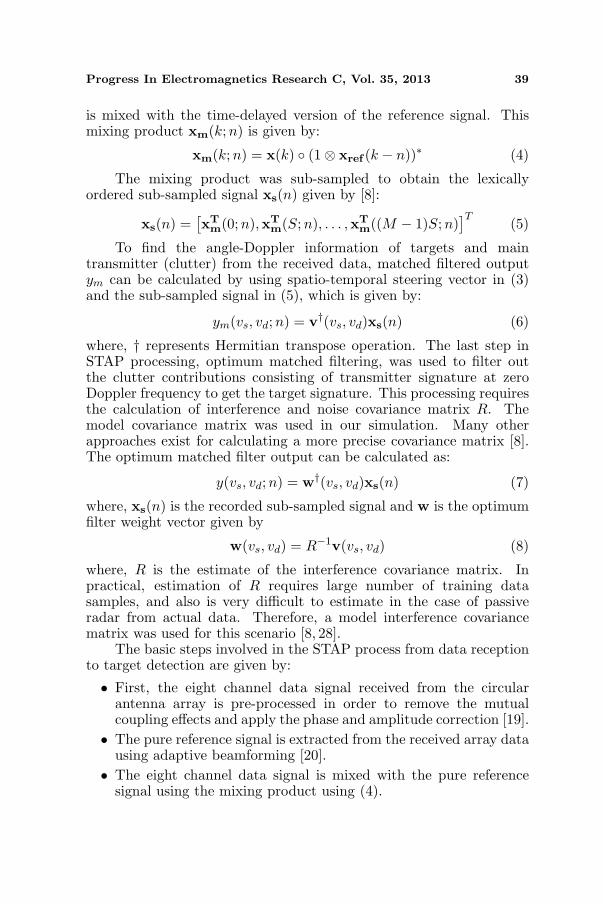
is mixed with the time-delayed version of the reference signal. Thismixing product xm(k;n) is given by:
xm(k; n) = x(k) ◦ (1⊗ xref (k − n))∗ (4)
The mixing product was sub-sampled to obtain the lexicallyordered sub-sampled signal xs(n) given by [8]:
xs(n) =[xT
m(0;n),xTm(S; n), . . . ,xT
m((M − 1)S; n)]T
(5)
To find the angle-Doppler information of targets and maintransmitter (clutter) from the received data, matched filtered outputym can be calculated by using spatio-temporal steering vector in (3)and the sub-sampled signal in (5), which is given by:
ym(vs, vd; n) = v†(vs, vd)xs(n) (6)
where, † represents Hermitian transpose operation. The last step inSTAP processing, optimum matched filtering, was used to filter outthe clutter contributions consisting of transmitter signature at zeroDoppler frequency to get the target signature. This processing requiresthe calculation of interference and noise covariance matrix R. Themodel covariance matrix was used in our simulation. Many otherapproaches exist for calculating a more precise covariance matrix [8].The optimum matched filter output can be calculated as:
y(vs, vd;n) = w†(vs, vd)xs(n) (7)
where, xs(n) is the recorded sub-sampled signal and w is the optimumfilter weight vector given by
w(vs, vd) = R−1v(vs, vd) (8)
where, R is the estimate of the interference covariance matrix. Inpractical, estimation of R requires large number of training datasamples, and also is very difficult to estimate in the case of passiveradar from actual data. Therefore, a model interference covariancematrix was used for this scenario [8, 28].
The basic steps involved in the STAP process from data receptionto target detection are given by:
• First, the eight channel data signal received from the circularantenna array is pre-processed in order to remove the mutualcoupling effects and apply the phase and amplitude correction [19].
• The pure reference signal is extracted from the received array datausing adaptive beamforming [20].
• The eight channel data signal is mixed with the pure referencesignal using the mixing product using (4).
40 Mahmood et al.
• The spatial and temporal steering vectors given by (1) and (2)are used to calculate spatio-temporal steering vector also knownas scanning vector given by (3).
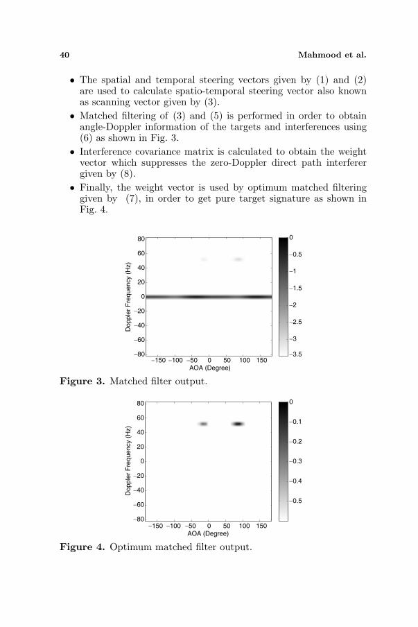
• Matched filtering of (3) and (5) is performed in order to obtainangle-Doppler information of the targets and interferences using(6) as shown in Fig. 3.
• Interference covariance matrix is calculated to obtain the weightvector which suppresses the zero-Doppler direct path interferergiven by (8).
• Finally, the weight vector is used by optimum matched filteringgiven by (7), in order to get pure target signature as shown inFig. 4.
AOA (Degree)
Dopple
r F
requency (
Hz)
−150 −100 −50 0 50 100 150 −80
−60
−40
−20
0
20
40
60
80
−3.5
−3
−2.5
−2
−1.5
−1
−0.5
0
Figure 3. Matched filter output.
AOA (Degree)
Dopp
ler
Fre
que
ncy (
Hz)
−150 −100 −50 0 50 100 150 −80
−60
−40
−20
0
20
40
60
80
−0.5
−0.4
−0.3
−0.2
−0.1
0
Figure 4. Optimum matched filter output.

Progress In Electromagnetics Research C, Vol. 35, 2013 41
3. DATA PROCESSING RESULTS
All the signal processing steps in Fig. 2, were first implementedin MATLAB environment which will be discussed in this section.Secondly, the signal processing steps for STAP processor, implementedon Xilinx Virtex-6 FPGA will be discussed in Section 4. Thedata reception scenario contains a non-cooperative FM transmitter at924MHz installed 600 meters away from the circular antenna array.A single target vehicle, moving towards the array at around 90◦ witha speed of 60 km/h. After receiving the eight channel signal, post-processing of the data was performed using MATLAB. This results inseparating the pure reference signal from the received eight channeldata signal [20]. The reference and eight-channel data signals are thenfed to STAP processor. The adaptive matched filter output using (6)is shown in Fig. 3, which confirms the transmitter at −30◦ with zero-Doppler frequency and a very weak moving target signature at 90◦with 52 Hz Doppler.
Optimum matched filtering using (7) is then used to effectivelyremove the zero-Doppler frequency components as shown in Fig. 4,and leaving the very strong target signature.
Figure 5. STAP processing blockset designed for FPGA.
42 Mahmood et al.
4. HARDWARE IMPLEMENTATION
The challenging part of our research lies in the FPGA implementationof STAP algorithm on passive bistatic radar using uniform circulararray. We want to develop a compact, light-weight and high-speedpassive radar system on which STAP algorithm can be implemented.In this paper, Xilinx Virtex-6 FPGA was used to design the dataprocessing steps of STAP, as shown in Fig. 5; initially for post-processing of the received data.
The designed model includes phase-angle and Doppler-bin buffersthat scan the received data to find the respective target bearingangle and Doppler. Various control blocks were used to control theinput data to perform respective tasks of STAP processor. Addressgenerator block was used to assign the addresses to the input datawhen arrived at the input of dual-port RAM blocks. As the receiveddata is complex, therefore, complex multipliers are needed for allmultiplication operations. The adder block was used for multiplicationoperations to add every row of data and store the value at specific RAMaddress.
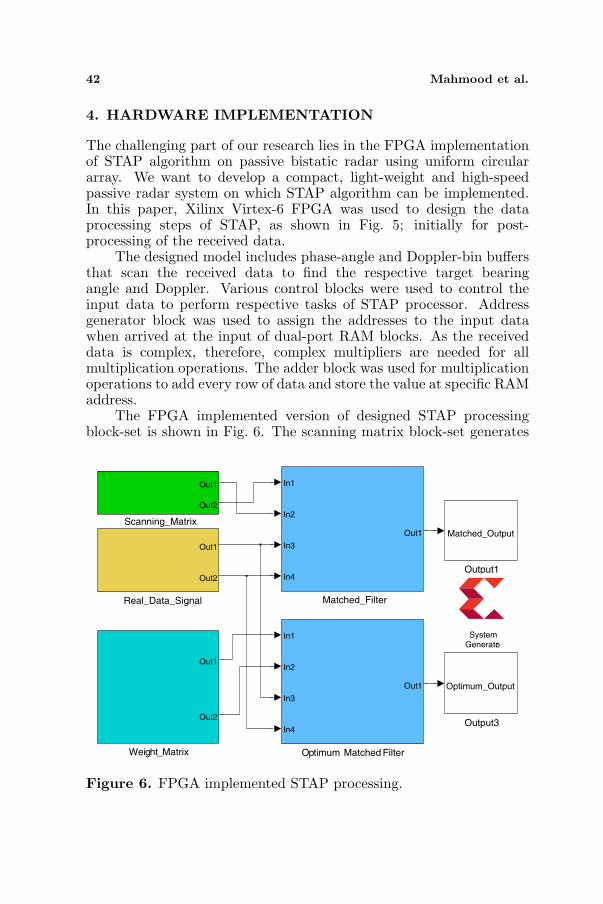
The FPGA implemented version of designed STAP processingblock-set is shown in Fig. 6. The scanning matrix block-set generates
Weight_Matrix
Out1
Out2
Scanning_Matrix
Out1
Out2
Real_Data_Signal
Out1
Out2
Output3
Optimum_Output
Output1
Matched_Output
Optimum Matched Filter
In1
In2
In3
In4
Out1
Matched_Filter
In1
In2
In3
In4
Out1
SystemGenerator
Figure 6. FPGA implemented STAP processing.
Progress In Electromagnetics Research C, Vol. 35, 2013 43
Out11
Terminator2
Terminator1
Reset Module
Out1
Real2
Out
Real#Imag toComplex3
Re
Im
RAM 2
addra
dina
wea
addrb
dinb
web
enb
A
B
RAM 1
addra
dina
wea
addrb
dinb
web
enb
A
B
OutputControl Unit
Out1
Out2
Out3
OutputAddress Generator
In1 Out1
InputControl Unit
Out1
InputAddress Generator
In1 Out1
Imag2
Out
Delay2
z#14
Delay1
z#14
Complex Multiplier 3.1
ar
ai
br
bi
pr
pi
Adder
In1
In2
In3
Out1
Out2
In4
4
In3
3
In2
2
In1
1
Fix_88_78
Fix_24_16
Fix_24_16
Fix_52_44
Fix_52_44
Fix_52_44
Fix_52_44
Fix_52_44
double
double
Bool Bool
Fix_88_78
Bool
UFix_10_0
UFix_10_0
Fix_52_44
Fix_52_44
Bool
Fix_24_16
Fix_24_16
Fix_63_62
double (c)
Fix_63_62
Figure 7. FPGA matched filter processing.
Real-Imag toComplex2
Re
Im
Real-Imag toComplex1
Re
Im
Output2
Optimum_Output
Output1
Matched_Output
Circular_Optimumhwcosim
Imag2
Real2
JTAGCo-sim
Circular_Matchedhwcosim
Imag1
Real1
JTAGCo-sim
SystemGenerator
double (c)
double
double
double
double (c)
double
Figure 8. Hardware co-simulation model.
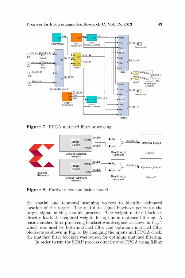
the spatial and temporal scanning vectors to identify estimatedlocation of the target. The real data signal block-set generates thetarget signal mixing module process. The weight matrix block-setdirectly loads the required weights for optimum matched filtering. Abasic matched filter processing blockset was designed as shown in Fig. 7which was used by both matched filter and optimum matched filterblocksets as shown in Fig. 6. By changing the inputs and FPGA clock,the matched filter blockset was reused for optimum matched filtering.
In order to run the STAP process directly over FPGA using Xilinx

44 Mahmood et al.
Figure 9. Optimum matched filter output from FPGA.
Table 1. Resources and power utilization summary of matchedfiltering.
On-Chip Components AvailableMatched Filtering Power
(W)Used Utilized (%)
Flipflops 301440 1993 0.7 0.09
Slice LUT’s 150720 1704 0.01 0.03
Block RAM’s 416 8 1.9 0.125
IO’s 600 203 33.8 0.418
DSP48E1’s 768 40 5.2 0.039
Leakage Power - 3.443
Total Power - 4.145
System Generator, hardware co-simulation model as shown in Fig. 8was needed which takes the received target data from computer andmanipulates it separately with matched filtering and optimum matchedfiltering and transfers the result back to computer to display the angle-Doppler plot of the target as shown in Fig. 9. The obtained resultsare in good agreement with MATLAB processing result as shown inFig. 4.
4.1. Hardware Timing and Power Analysis
The next step in FPGA implementation is to find out thecomputational and the power requirements. The results of the timing

Progress In Electromagnetics Research C, Vol. 35, 2013 45
Table 2. Resources and power utilization summary of optimummatched filtering.
On-ChipComponents
AvailableOptimum Matched Filtering Power
(W)Used Utilized (%)Flipflops 301440 1283 0.42 0.08
Slice LUT’s 150720 3197 0.02 0.012Block RAM’s 416 336 80.77 0.068
IO’s 600 209 34.83 0.248DSP48E1’s 768 24 3.125 0.011
Leakage Power - 3.435Total Power - 3.854
Table 3. Computation time and frequency analysis.
ProcessingMATLABProcessing
(sec)
FPGAProcessing
(nsec)
MaximumFPGA
Freq. (MHz)Matched Filtering 7 4.964 201.450Optimum Matched
Filtering9.8 9.944 100.563
and power analysis of matched filtering and optimum matched filteringare presented in Table 1 and Table 2 respectively. The results showthat the process of matched filtering requires more power while utilizingless resources as compared to the process of optimum matched filteringwhich requires less power while utilizing more on-chip resources.
The timing analysis as shown in Table 3, shows a huge differencebetween MATLAB and FPGA processing time. It is also observedthat the matched filtering process requires less FPGA clock period ascompared to optimum matched filtering because it uses less resourcesas compared to optimum one. The maximum frequency required byFPGA depends on the FPGA clock period. The lesser the clock periodof FPGA, greater will be the operating FPGA frequency and vice versa.
5. CONCLUSION
MATLAB Simulation and the hardware implementation of STAPalgorithm for Passive Bi-static Radar (PBR) using uniform circulararray was presented. This implementation was verified with the
46 Mahmood et al.
real field experimental data using FM as transmitter of opportunity.The results are based on offline processing of the data, both forMATLAB and FPGA processing. The MATLAB processing resultsalong with the FPGA output shows that the zero-Doppler clutter canbe effectively filtered out by using optimum matched filtering. Futurework will focus on real-time target detection using STAP processingto achieve a dedicated radar system for the proposed technique.
ACKNOWLEDGMENT
The above research has been sponsored by King Abdulaziz City forScience and Technology (KACST) under grant number 09-ELE-729-02and D-S-12-0107.
REFERENCES
1. Ul Mahmood, Z., M. Alam, K. Jamil, and M. Elnamaky,“Implementation of space-time adaptive processing (STAP) fortarget detection in passive bi-static radar,” PIERS Proceedings,724–727, Kuala Lumpur, Malaysia, Mar. 27–30, 2012.
2. Ul Mahmood, Z., M. Alam, K. Jamil, and M. Elnamaky,“On modeling and hardware implementation of space-timeadaptive processing (STAP) for target detection in passive bi-static radar,” The 11th International Conference on InformationSciences, Signal Processing and Their Applications: Main Tracks(ISSPA2012-Tracks), 1040–1044, 2012.
3. Gong, Q. and Z.-D. Zhu, “Study STAP algorithm on interferencetarget detect under non-homogenous environment,” Progress InElectromagnetics Research, Vol. 99, 211–224, 2009.
4. Sarkar, T. K. and R. Adve, “Space-time adaptive processing usingcircular arrays,” Antennas and Propagation Magazine, Vol. 43,No. 1, 138–143, 2001.
5. Zatman, M., “Circular array STAP,” IEEE Transactions onAerospace and Electronic Systems, Vol. 36, No. 2, 510–517, 2000.
6. Belfiori, F., S. Monni, W. Van Rossum, and P. Hoogeboom,“Side-lobe suppression techniques for a uniform circular array,”European Radar Conference (EuRAD), 113–116, 2010.
7. Nguyen, H. N., J. D. Hiemstra, and J. S. Goldstein, “Thereduced rank multistage Wiener filter for circular array STAP,”Proceedings of the IEEE Radar Conference, 66–70, 2003.
8. Neyt, X., J. Raout, M. Kubica, V. Kubica, S. Roques, M. Acheroy,

Progress In Electromagnetics Research C, Vol. 35, 2013 47
and J. G. Verly, “Feasibility of STAP for passive GSM-basedradar,” IEEE Conference on Radar , 546–551, 2006.
9. Kubica, M., V. Kubica, X. Neyt, J. Raout, S. Roques, andM. Acheroy, “Optimum target detection using illuminator ofopportunity,” IEEE Conference on Radar , 417–424, 2006.
10. Melvin, W. L., “A STAP overview,” Aerospace and ElectronicSystems Magazine, Vol. 19, No. 1, 19–35, 2004.
11. Sarkar, T. K., H. Wang, S. Park, R. Adve, J. Koh, K. Kim,Y. Zhang, M. C. Wicks, and R. D. Brown, “A deterministic least-squares approach to space-time adaptive processing (STAP),”IEEE Transactions on Antennas and Propagation, Vol. 49, No. 1,91–103, 2001.
12. Homer, J., K. Kubik, B. Mojarrabi, I. D. Longstaff, E. Donskoi,and M. Cherniakov, “Passive bi-static radar sensing with LEOSbased transmitters,” IEEE International Geo-science and RemoteSensing Symposium, (IGARSS), Vol. 1, 438–440, 2002.
13. Chetty, K., K. Woodbridge, G. Hui, and G. E. Smith, “Passivebi-static WiMAX radar for marine surveillance,” IEEE RadarConference, 188–193, 2010.
14. Colone, F., P. Falcone, C. Bongioanni, and P. Lombardo,“WiFi-based passive bi-static radar: Data processing schemesand experimental results,” IEEE Transactions on Aerospace andElectronic Systems, Vol. 48, No. 2, 1061–1079, 2012.
15. Howland, P. E., D. Maksimiuk, and G. Reitsma, “FM radiobased bi-static radar,” IEE Proceedings — Radar, Sonar andNavigation, Vol. 152, No. 3, 107–115, 2005.
16. Tan, D. K. P., H. Sun, Y. Lu, M. Lesturgie, and H. L. Chan,“Passive radar using global system for mobile communicationsignal: Theory, implementation and measurements,” IEEProceedings — Radar, Sonar and Navigation, Vol. 152, No. 3,116–123, 2005.
17. Berger, C. R., B. Demissie, J. Heckenbach, P. Willett,and S. Zhou, “Signal processing for passive radar usingOFDM waveforms,” IEEE Journal of Selected Topics in SignalProcessing , Vol. 4, No. 1, 226–238, 2010.
18. Cai M., F. He, and L. Wu, “Application of UKF algorithm fortarget tracking in DTV-based passive radar,” 2nd InternationalCongress on Image and Signal Processing, (CISP), 1–4, 2009.
19. Jamil, K., M. Alam, M. Hadi, and Z. Alhekail, “A multi-bandmulti-beam software-defined passive radar Part I: System design,”IET Radar Conference, 2012.

48 Mahmood et al.
20. Alam, M., K. Jamil, Z. Alhekail, and S. Alhumaidi, “A multi-band multi-beam software-defined passive radar Part II: Signalprocessing,” IET Radar Conference, 2012.
21. De Maio, A., S. De Nicola, Y. Huang, D. P. Palomar, S. Zhang,and A. Farina, “Code design for radar STAP via optimizationtheory,” IEEE Transactions on Signal Processing, Vol. 58, No. 2,679–694, 2010.
22. Palmer, J. E. and S. J. Searle, “Evaluation of adaptive filteralgorithms for clutter cancellation in passive bistatic radar,” IEEERadar Conference (RADAR), 493–498, 2012.
23. Searle, S., S. Howard, and J. Palmer, “Remodulation of DVBTsignals for use in passive bistatic radar,” Conference Record ofthe Forty Fourth Asilomar Conference on Signals, Systems andComputers (ASILOMAR), 1112–1116, 2010.
24. Harms, H. A., L. M. Davis, and J. Palmer, “Understanding thesignal structure in DVB-T signals for passive radar detection,”IEEE Radar Conference, 532–537, 2010.
25. Yang, Z. C., Z. Liu, X. Li, and L. Nie, “Performance analysisof STAP algorithms based on fast sparse recovery techniques,”Progress In Electromagnetics Research B , Vol. 41, 251–268, 2012.
26. Liu, Z., X. Wei, and X. Li, “Adaptive clutter suppressionfor airborne random pulse repetition interval radar based oncompressed sensing,” Progress In Electromagnetics Research,Vol. 128, 291–311, 2012.
27. Wu, D., Z. Xu, L. Zhang, Z. Xiong, and S. Xiao, “Performanceanalysis of polarization-space-time three-domain joint processingfor clutter suppression in airborne radar,” Progress In Electromag-netics Research, Vol. 129, 579–601, 2012.
28. Richards, M. A., Fundamentals of Radar Signal Processing, TataMcGraw-Hill Education, 2005.