Embed Size (px)
Citation preview

International Journal of Science and Research (IJSR) ISSN (Online): 2319-7064
Index Copernicus Value (2013): 6.14 | Impact Factor (2013): 4.438
Volume 4 Issue 5, May 2015
www.ijsr.net Licensed Under Creative Commons Attribution CC BY
FPGA based Underwater System for Ultrasound
Communication
Pooja Sabale1, S.T. Khot
2
1Department of Electronics and Telecommunication Engineering, B.V.C.O.E.W Pune, India
2Professor at Department of Electronics and Telecommunication Engineering, B.V.C.O.E.W Pune, India
Abstract: The paper presents the design consideration, implementation details of acoustic modem. The underwater channel is highly
variable; each point can have changes in signal, which change according to environmental factors as well as the locations of the
communicating nodes. Reliable communication becomes difficult. Modulations schemes are used such as ASK; this design uses
commercial ultrasonic transducer of 200 kHz bandwidth. Transmitted message can be displayed as well as it can be analyzed using
different simulation tools at base station. Underwater modem has three parts as an underwater sensor, transceiver (matching pre-
amplifier and amplifier), a digital platform for control and signal processing. There is interfacing between sensors and controller i.e.
FPGA. Also comparison between various output signals is checked.
Keywords: Field Programmable Gate Array, Acoustic modem, modulation techniques
1. Introduction
The interest about underwater application is increasing due
to physical, chemical and biological time series data from
long term sensor. Despite the substantial effort for
monitoring ecological aspects of aquatic systems, the
comparison between Underwater modem and on ground
radio is given below.
Table 1: Differences between underwater and On ground
communication modem Sr. no. Underwater acoustic On ground Radio
1 Low bandwidth (KHz) High bandwidth (MHz)
2 Long delay Short delay 3 Distance dependent on
bandwidth Distance independent on
bandwidth
4 Few simulation tools
available Several simulation tools
available 5 Hard to experiment Easy to experiment
The table shows main differences between underwater
acoustic network and terrestrial radio network. The preferred
mode of wireless communication in these networks is based
on acoustic signals. This is due to the fact that radio
frequencies suffer high attenuation underwater. Optical
communication is possible but only in clear water at
relatively short distances. Now a day‟s there is interest in the
design and deployment of underwater acoustic
communication network.
Application of this modem will be in oceanographic data
collection, pollution monitoring offshore exploration,
disaster prevention, assisted navigation & tactical
surveillance application unmanned or autonomous
underwater vehicles equipped with sensor will enable to
gathering of scientific data. It consists of variable number of
sensor & vehicles that are deployed to perform collaborative
monitoring task over give area. This provides the reliable
and energy efficient communication adaptive physical layer.
The underwater devices are battery operated so energy
efficiency is important. In this advanced modulation
techniques are used such as ASK.
The underwater modem consists of three main parts as
underwater transducer, analog transceiver and digital
platform for control and signal processing .The transducer is
an ultrasound sensor for reliable communication. The sensor
has frequency of 200 kHz and it has high performance and
high reliability. The analog transceiver consists of a high
power transmitter and a highly sensitive receiver both of
which are optimized to operate in the transducer‟s resonance
frequency range. The transmitter is responsible for
amplifying the modulated signal from the digital hardware
platform and sending it to the transducer so that it may be
transmitted through the water. The receiver amplifies the
signal that is detected by the transducer so that the digital
hardware platform can effectively demodulate the signal and
analyze the transmitted data. Due to its high linearity, the
transmitter may be used with any modulation technique that
can be programmed into the digital hardware platform.
The main purpose of a communication system is to transfer
information from a source to a Destination. A message
signal containing information is used to control parameters
of a carrier signal i.e. the information is embedded onto the
carrier. The carrier could either a sinusoidal wave or a pulse
train. At the destination the carrier plus message must be
demodulated so that the message can be received. If the
message signal controls-
Amplitude = Amplitude Shift Keying (ASK)
Frequency = Frequency Shift Keying (FSK)
Phase = Phase Shift Keying (PSK)
Table shows the ASK modem‟s time and frequency
parameters which were selected based on the properties of
the transducer. The „mark‟ frequency represents the
frequency used to represent a digital „1 ‟ when converted to
baseband and the „space‟ frequency represents the frequency
used to represent a digital „0‟ when converted to baseband.
The sampling frequency is used for sending and receiving
the modulated waveform on the carrier frequency while the
baseband frequency is used for all baseband processing.
Paper ID: SUB154444 1515

International Journal of Science and Research (IJSR) ISSN (Online): 2319-7064
Index Copernicus Value (2013): 6.14 | Impact Factor (2013): 4.438
Volume 4 Issue 5, May 2015
www.ijsr.net Licensed Under Creative Commons Attribution CC BY
Table 2: Time and frequency parameters of ASK Properties Assignment
Modulation ASK
Carrier frequency 40KHz Mark frequency NA Space frequency NA Symbol duration 1.04ms
Baseband Frequency 960
2. Underwater Modem Design
In this the main hardware parts for the modem are designed.
This consists of the blocks for the modulation and
demodulation process. From this the physical layer is
designed through the below hardware parts.
Figure 1: Block diagram of underwater acoustic modem
A. Modulation
There are many different types of signals used for underwater
communication. These include FSK, PSK, orthogonal
frequency direct modulation (OFDM), and DSSS. While an
adaptive modem can ideally switch between any modulations
schemes, for this ASK modulation is used. ASK is a fairly
simple and widely used modulation scheme in underwater
communication due to its intrinsic robustness to time and
frequency spreading. Our receiver uses a non-coherent
energy detection demodulation method.
B. FPGA
The FPGA orchestrates the digital platform. This includes
providing data for serial communication, setting the
parameters for the various parts of the digital hardware, and
ultimately interfacing with higher level network stack.
C. Amplifiers
Pulses from the control unit to the ultrasonic transmitter are
amplified using a driver and the analog signal from the
receiver is amplified using a precision instrumentation
amplifier. The amplifier at receiver has gain of 1000. The
output of this amplifier is fed to level shifter.
D. Level shifter
A major component of an adaptive modem is the ability to
change aspects of the modem including selecting a
modulation scheme, the data rate, the transmit power, and
other configurable portions of the design. Many of these
depend upon current and future characteristics of the
acoustic channel. This is to shift the level from NRZ to RZ.
E. Echo cancellation
In this multipath are rejected, as the signal from transmitter
will reflect in multiple paths to receiver. At this part the
useful path is selected and others are rejected.
F. Envelop Detector
This is demodulation block. Envelop detector is one of the
technique used for demodulation. The original wave is
recovered from this method.
3. Hardware Platform
Papilio One XC3s250 Spartan3 we will be using. Arduino
IDE we will use and Language of programming is somewhat
different than VHDL but it finally gets converted into Bit
file which can be loaded into FPGA. This IDE better handles
floating points and will give u better results that why we
have chosen this.
Figure 2: Spartan 3 QFP package
G. Specifications
Densities up to 33,192 logic cells, including optional shift
register or distributed RAM support
Efficient wide multiplexers, wide logic
Fast look-ahead carry logic
Enhanced 18 x 18 multipliers with optional pipeline
IEEE 1149.1/1532 JTAG programming/debug port
Hierarchical Select RAM™ memory architecture
Up to 648 Kbits of fast block RAM
Up to 231 Kbits of efficient distributed RAM
Up to eight Digital Clock Managers (DCMs)
Clock skew elimination (delay locked loop)
Frequency synthesis, multiplication, division
High-resolution phase shifting
Wide frequency range (5 MHz to over 300 MHz) Eight
global clocks plus eight additional clocks per each half of
device, plus abundant low-skew routing.
4. Ultrasound Sensors
The table.3 below shows specifications of the ultrasound
sensor used and the fig 3 shows diagram of sensor. It is
Paper ID: SUB154444 1516

International Journal of Science and Research (IJSR) ISSN (Online): 2319-7064
Index Copernicus Value (2013): 6.14 | Impact Factor (2013): 4.438
Volume 4 Issue 5, May 2015
www.ijsr.net Licensed Under Creative Commons Attribution CC BY
200khz transceivers can be used as both transmitter and
receiver.
Table 3: Specifications of sensor
These sensors are small in size and simple to use. It doesn‟t
need any high security measures. Also it can be automated
with the controller or FPGA. Capacitive transducer act as
both transmitter and receiver for communication. Sensor is of
higher efficiency and has very high reliability. These are safe
for use with simple operation. This can be interfaced with the
display devices easily. They can perform easily as they are
small in size. Ultrasound waves are more noise free than the
other waves of communication.
Figure 3: Underwater Environment and the sensor nodes
Figure 4: Diagram of Ultrasound sensor
5. PCB Layout
A printed circuit board (PCB) mechanically supports and
electrically connects electronic components using conductive
tracks, pads and other features etched from copper sheets
laminated onto a non-conductive substrate. PCBs can be
single sided (one copper layer), double sided (two copper
layers) or multi-layer. Conductors on different layers are
connected with plated-through holes called vias. Advanced
PCBs may contain components - capacitors, resistors or
active devices - embedded in the substrate.
Printed circuit boards are used in all but the simplest
electronic products. Alternatives to PCBs include wire wrap
and point-to-point construction. PCBs require the additional
design effort to lay out the circuit but manufacturing and
assembly can be automated. Manufacturing circuits with
PCBs is cheaper and faster than with other wiring methods as
component are mounted and wired with one single part.
Furthermore, operator wiring errors are eliminated.
Figure 5: PCB layout using Dip trace software
6. Result
Here I have taken the measurements. The voltage at receiver
and distance measured between transmitter and receiver are
measured. The curve is plotted from the readings.
Figure 6: Voltage Vs Distance Curve at Reciever
From this we can check the signal quality at reciver. By
cheking the results we can again and again take the reading
and improve the signal quality.
Paper ID: SUB154444 1517
International Journal of Science and Research (IJSR) ISSN (Online): 2319-7064
Index Copernicus Value (2013): 6.14 | Impact Factor (2013): 4.438
Volume 4 Issue 5, May 2015
www.ijsr.net Licensed Under Creative Commons Attribution CC BY
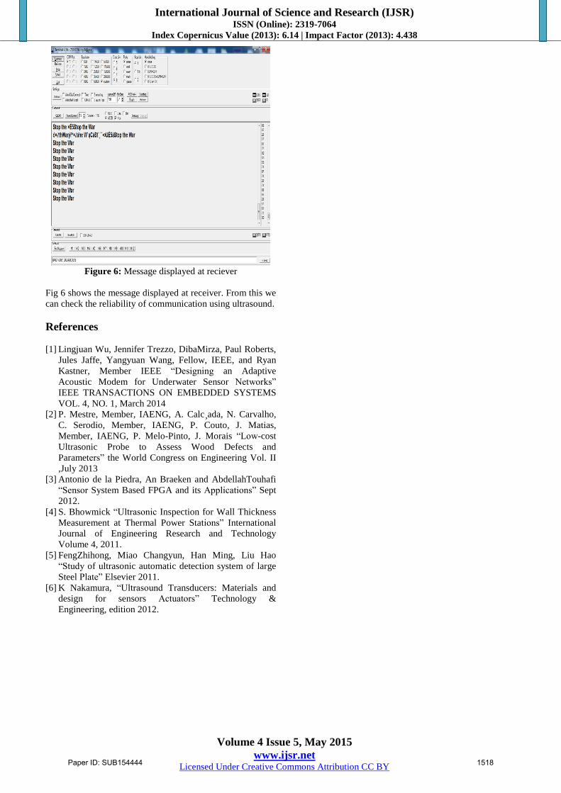
Figure 6: Message displayed at reciever
Fig 6 shows the message displayed at receiver. From this we
can check the reliability of communication using ultrasound.
References
[1] Lingjuan Wu, Jennifer Trezzo, DibaMirza, Paul Roberts,
Jules Jaffe, Yangyuan Wang, Fellow, IEEE, and Ryan
Kastner, Member IEEE “Designing an Adaptive
Acoustic Modem for Underwater Sensor Networks”
IEEE TRANSACTIONS ON EMBEDDED SYSTEMS
VOL. 4, NO. 1, March 2014
[2] P. Mestre, Member, IAENG, A. Calc¸ada, N. Carvalho,
C. Serodio, Member, IAENG, P. Couto, J. Matias,
Member, IAENG, P. Melo-Pinto, J. Morais “Low-cost
Ultrasonic Probe to Assess Wood Defects and
Parameters” the World Congress on Engineering Vol. II
,July 2013
[3] Antonio de la Piedra, An Braeken and AbdellahTouhafi
“Sensor System Based FPGA and its Applications” Sept
2012.
[4] S. Bhowmick “Ultrasonic Inspection for Wall Thickness
Measurement at Thermal Power Stations” International
Journal of Engineering Research and Technology
Volume 4, 2011.
[5] FengZhihong, Miao Changyun, Han Ming, Liu Hao
“Study of ultrasonic automatic detection system of large
Steel Plate” Elsevier 2011.
[6] K Nakamura, “Ultrasound Transducers: Materials and
design for sensors Actuators” Technology &
Engineering, edition 2012.
Paper ID: SUB154444 1518