Embed Size (px)
Citation preview
Princes Highway Upgrade – Gerringong to Bomaderry
Foxground and Berry Bypass
Report on preparation of route feasibility comparative cost estimates
Appendix F1
Construction methodology:
Construction method statements – major structures
Berry Bypass: Construction Method Statements
Peter Stewart 4 May 2012 1
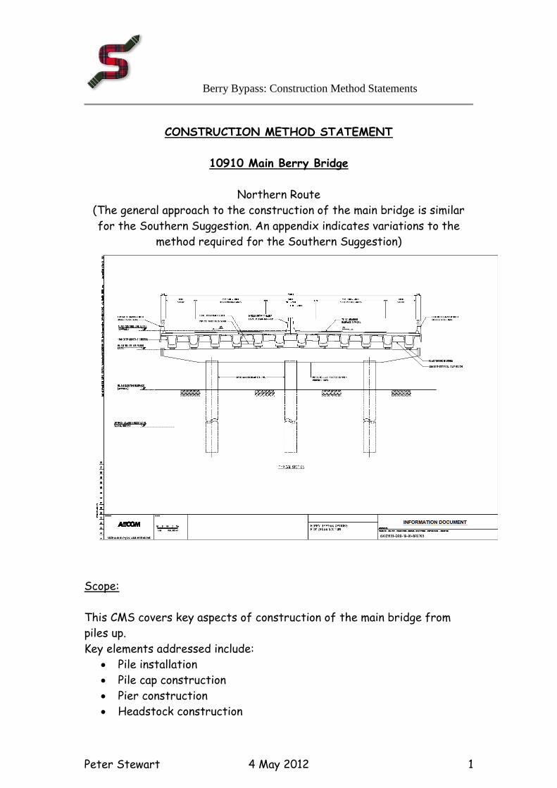
CONSTRUCTION METHOD STATEMENT
10910 Main Berry Bridge
Northern Route
(The general approach to the construction of the main bridge is similar
for the Southern Suggestion. An appendix indicates variations to the
method required for the Southern Suggestion)
Scope:
This CMS covers key aspects of construction of the main bridge from
piles up.
Key elements addressed include:
Pile installation
Pile cap construction
Pier construction
Headstock construction
Berry Bypass: Construction Method Statements
Peter Stewart 4 May 2012 2
Super T beam erection
Deck, diaphragms, link slabs and precast parapets
Construction Method:
Basics: Assumptions are as follows:
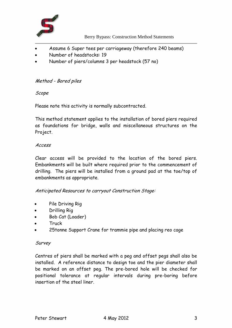
Hard surface access is available to all pile caps. Main access point
from Woodhill Mountain Road with auxiliary access from princes
Highway at Northern Interchange to reach structure for first two
spans.
The piles are already in place having been driven from GL. The
upper section will project sufficient to allow the clamping of the pier
formwork
Creek diversions or alternatives are in place to ensure construction
is in the dry (although pumping may be required to keep the excavation
dry)
3 no 1200diam circular piers (uniform shape from bottom to top)
extend upwards from 3 no 1200 diam piles
No pile caps are anticipated at time of writing but MS included
should design change.
Super tee Beams are 32.250m span and 1.5m deep weighing
approximately 55t.
Assume 20 spans at approx. 30m = 607.5m
North
Berry Bypass: Construction Method Statements
Peter Stewart 4 May 2012 3
Assume 6 Super tees per carriageway (therefore 240 beams)
Number of headstocks: 19
Number of piers/columns 3 per headstock (57 no)
Method - Bored piles
Scope
Please note this activity is normally subcontracted.
This method statement applies to the installation of bored piers required
as foundations for bridge, walls and miscellaneous structures on the
Project.
Access
Clear access will be provided to the location of the bored piers.
Embankments will be built where required prior to the commencement of
drilling. The piers will be installed from a ground pad at the toe/top of
embankments as appropriate.
Anticipated Resources to carryout Construction Stage:
Pile Driving Rig
Drilling Rig
Bob Cat (Loader)
Truck
25tonne Support Crane for trammie pipe and placing reo cage
Survey
Centres of piers shall be marked with a peg and offset pegs shall also be
installed. A reference distance to design toe and the pier diameter shall
be marked on an offset peg. The pre-bored hole will be checked for
positional tolerance at regular intervals during pre-boring before
insertion of the steel liner.
Berry Bypass: Construction Method Statements
Peter Stewart 4 May 2012 4
Driving of Steel Liners
If required, steel liners will be driven using the pile driving rig set up over
the pier set centre peg. Liners will be pitched and driven to the founding
level given on the drawings. Where required the liner will be driven
progressively with excavation and removal of material from within to
facilitate driving. Where ground conditions permit, predrilling of holes
marginally larger than the pile shoe outer diameter will be carried out
prior to insertion of the liner.
Drilling/Excavated Material Removal
The drilling rig fitted with the correct sized auger will be set up over the
driven steel liner or pier centre peg and drilling commenced.
Excavated material will be spun off the auger as it is withdrawn from the
hole. This material will be removed by the small loader either into
stockpile for later removal or directly into a truck for progressive
disposal to spoil. Drilling will proceed to the required founding level. If
this is into rock, a special rock cutting auger will be fitted to the Kelly
bar of the drilling rig to enable penetration to the required depth.
Alternatively a rock chopper may be used.
Steel Reinforcing Cage
After the founding condition in the pier has been accepted by the
Engineer, any temporary protective liner shall be withdrawn. The socket
will then be cleaned using a cleaning bucket and a pre-made steel
reinforcing cage will be lowered into and suitably secured in the bored
pier.
Concrete Placement
The bored pier will then be filled with the appropriate grade of concrete
using a suitable tremmie pipe or concrete pump with the finished surface
being brought to the appropriate R.L.
Anticipated Production Rates:
Berry Bypass: Construction Method Statements
Peter Stewart 4 May 2012 5
Allowance for approximately 5m/hour in other than rock material. Method – Pile Caps (if required)
Pile caps are excavated to the required level with 20t
excavator. The excavation will allow a 1m wide strip all around
to provide space to erect the pile cap formwork. The
excavation slopes will be at say 1:1. Some hand excavation will
be required around piles. A sump will be provided and a pump
used to keep the excavation dry if necessary. Spoil is side cast.
Perhaps later used to landscape over cap.
Piles will be trimmed back to the required level exposing the
reinforcement. Excavator fitting with crushing tool may be
required if concrete in pile is cast too high.
A 50mm concrete blinding will be placed over the underside of
the pile cap as a working platform.
Pile cap formwork (proprietary type) can be erected,
reinforcement cage placed or fixed insitu and the pile cap
poured. Concrete poured directly from ready mix truck. May
occasions where crane is required.
Anticipated Resources to carryout Construction Stage: 20 t excavator
Subcontract the FRP base
Anticipated Production Rates: Allow 5 days/pile cap (Note: Two no per location as there are
two parallel bridges one for each carriageway)
.
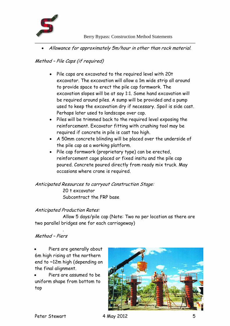
Method – Piers Piers are generally about
6m high rising at the northern
end to ~12m high (depending on
the final alignment.
Piers are assumed to be
uniform shape from bottom to
top
Berry Bypass: Construction Method Statements
Peter Stewart 4 May 2012 6
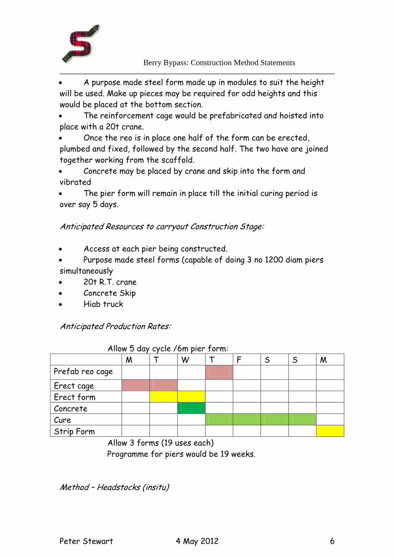
A purpose made steel form made up in modules to suit the height
will be used. Make up pieces may be required for odd heights and this
would be placed at the bottom section.
The reinforcement cage would be prefabricated and hoisted into
place with a 20t crane.
Once the reo is in place one half of the form can be erected,
plumbed and fixed, followed by the second half. The two have are joined
together working from the scaffold.
Concrete may be placed by crane and skip into the form and
vibrated
The pier form will remain in place till the initial curing period is
over say 5 days.
Anticipated Resources to carryout Construction Stage: Access at each pier being constructed.
Purpose made steel forms (capable of doing 3 no 1200 diam piers
simultaneously
20t R.T. crane
Concrete Skip
Hiab truck Anticipated Production Rates: Allow 5 day cycle /6m pier form:
M T W T F S S M
Prefab reo cage
Erect cage
Erect form
Concrete
Cure
Strip Form
Allow 3 forms (19 uses each)
Programme for piers would be 19 weeks.
Method – Headstocks (insitu)
Berry Bypass: Construction Method Statements
Peter Stewart 4 May 2012 7
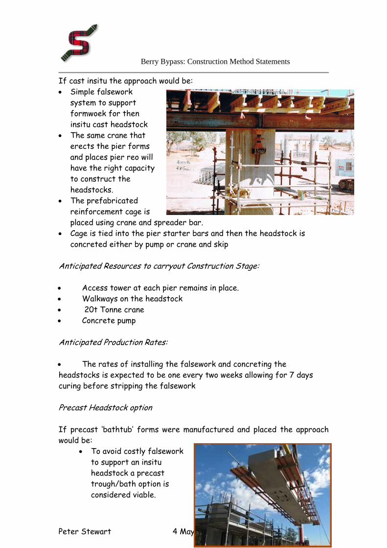
If cast insitu the approach would be:
Simple falsework
system to support
formwoek for then
insitu cast headstock
The same crane that
erects the pier forms
and places pier reo will
have the right capacity
to construct the
headstocks.
The prefabricated
reinforcement cage is
placed using crane and spreader bar.
Cage is tied into the pier starter bars and then the headstock is
concreted either by pump or crane and skip
Anticipated Resources to carryout Construction Stage: Access tower at each pier remains in place.
Walkways on the headstock
20t Tonne crane
Concrete pump
Anticipated Production Rates: The rates of installing the falsework and concreting the
headstocks is expected to be one every two weeks allowing for 7 days
curing before stripping the falsework
Precast Headstock option If precast ‘bathtub’ forms were manufactured and placed the approach
would be:
To avoid costly falsework
to support an insitu
headstock a precast
trough/bath option is
considered viable.
Berry Bypass: Construction Method Statements
Peter Stewart 4 May 2012 8
The same crane that erects the super tees as it will have the
right capacity to also place this precast trough.
Note all walkways are pre attached before lifting.
Starter bars protruding from the piers pass through holes in the
soffit of the headstock.
The reinforcement cage is placed and tied into the starter bars
and then the rest of the headstock is concreted.
Anticipated Resources to carryout Construction Stage:
Access tower at each pier remains in place.
Walkways on the headstock
200tonne Tonne crane
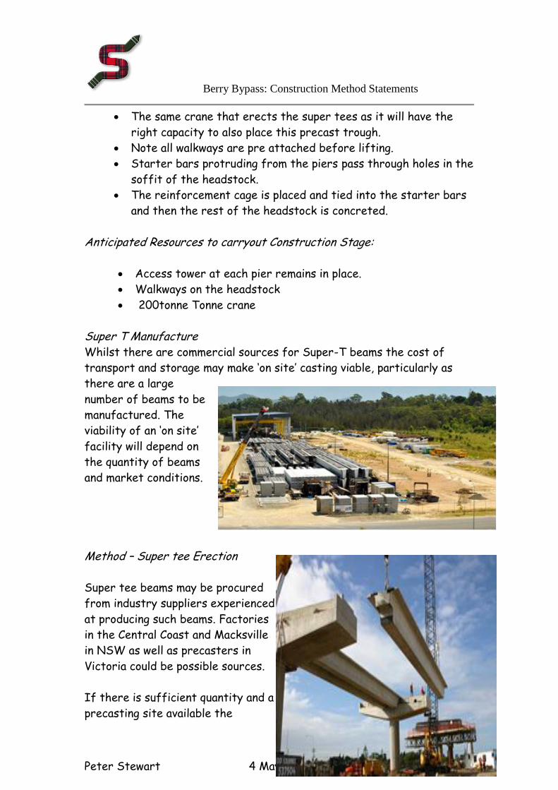
Super T Manufacture Whilst there are commercial sources for Super-T beams the cost of
transport and storage may make ‘on site’ casting viable, particularly as
there are a large
number of beams to be
manufactured. The
viability of an ‘on site’
facility will depend on
the quantity of beams
and market conditions.
Method – Super tee Erection
Super tee beams may be procured
from industry suppliers experienced
at producing such beams. Factories
in the Central Coast and Macksville
in NSW as well as precasters in
Victoria could be possible sources.
If there is sufficient quantity and a
precasting site available the

Berry Bypass: Construction Method Statements
Peter Stewart 4 May 2012 9
contractor may elect to manufacture “on site’ to save transport costs.
The proposed site for the truck rest stop may well be suitable to
accommodate the manufacturing facilities as well the beam storage area.
Adequate services would be required and this will need to be checked for
suitability.
Beams will be loaded onto a horse and jinker
haulage unit and brought to the site for
erection.
The beam will be brought alongside the piers
where the beam is to be erected.
Depending on the peculiarities of each location the crane required may
vary. For instance on the flood plain the crane can be placed close to the
beam both during lifting off the transport and placing on the headstocks.
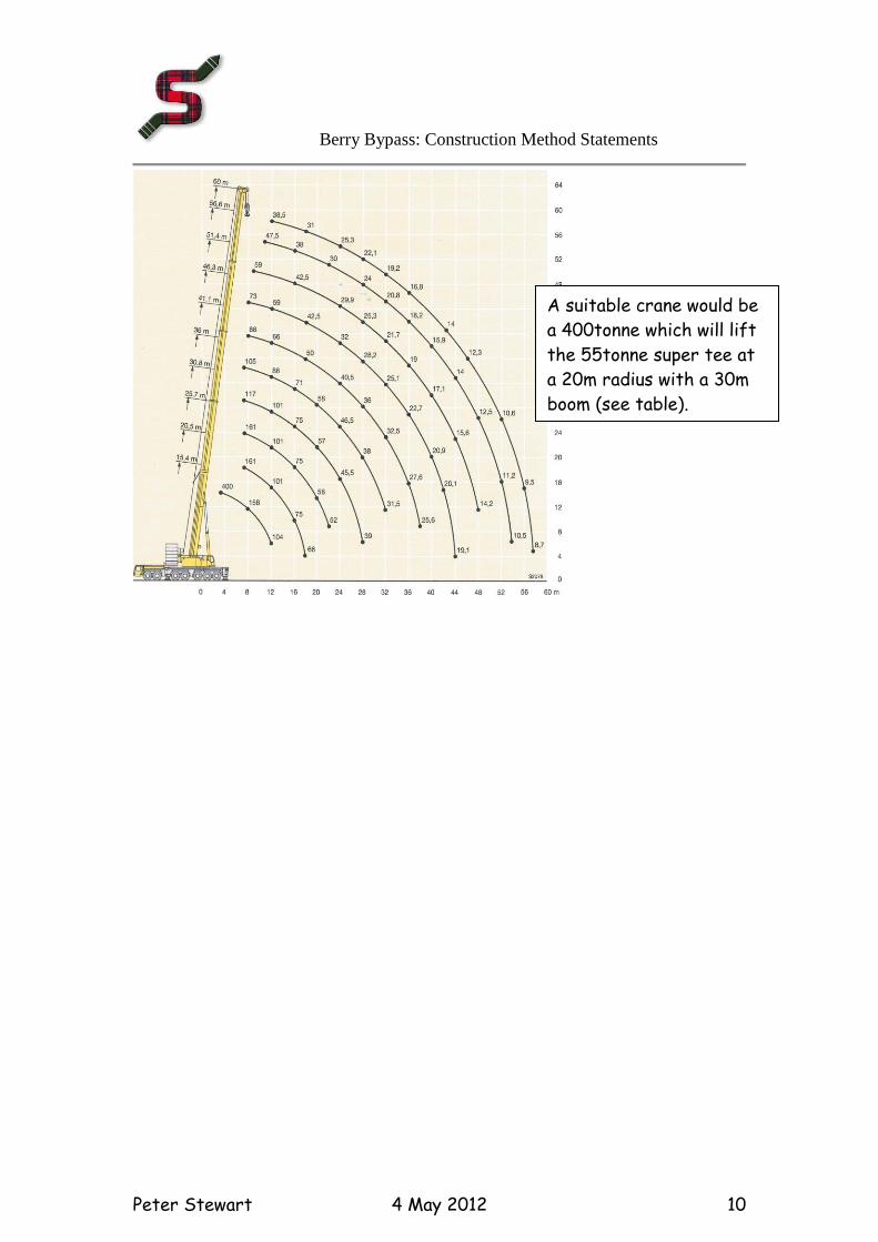
A suitable crane would be a 400tonne which will lift the 55tonne super
tee at a 20m radius with a 30m boom (see table). Crane pad layout shown
and layout for first six beams:
Layout for second 6 beams:
Berry Bypass: Construction Method Statements
Peter Stewart 4 May 2012 10
A suitable crane would be
a 400tonne which will lift
the 55tonne super tee at
a 20m radius with a 30m
boom (see table).
Berry Bypass: Construction Method Statements
Peter Stewart 4 May 2012 11
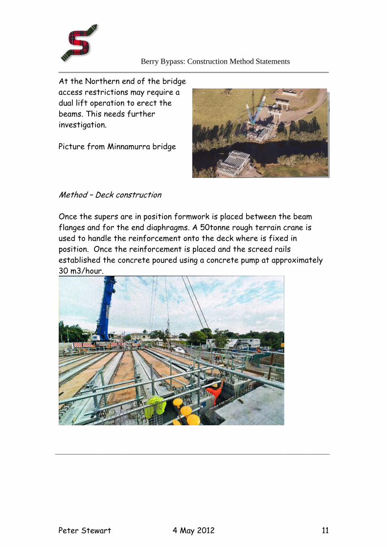
At the Northern end of the bridge
access restrictions may require a
dual lift operation to erect the
beams. This needs further
investigation.
Picture from Minnamurra bridge
Method – Deck construction Once the supers are in position formwork is placed between the beam
flanges and for the end diaphragms. A 50tonne rough terrain crane is
used to handle the reinforcement onto the deck where is fixed in
position. Once the reinforcement is placed and the screed rails
established the concrete poured using a concrete pump at approximately
30 m3/hour.
Berry Bypass: Construction Method Statements
Peter Stewart 4 May 2012 12
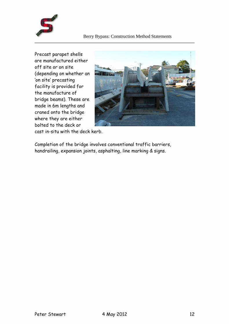
Precast parapet shells
are manufactured either
off site or on site
(depending on whether an
‘on site’ precasting
facility is provided for
the manufacture of
bridge beams). These are
made in 6m lengths and
craned onto the bridge
where they are either
bolted to the deck or
cast in-situ with the deck kerb.
Completion of the bridge involves conventional traffic barriers,
handrailing, expansion joints, asphalting, line marking & signs.
Berry Bypass: Construction Method Statements
Peter Stewart 4 May 2012 13
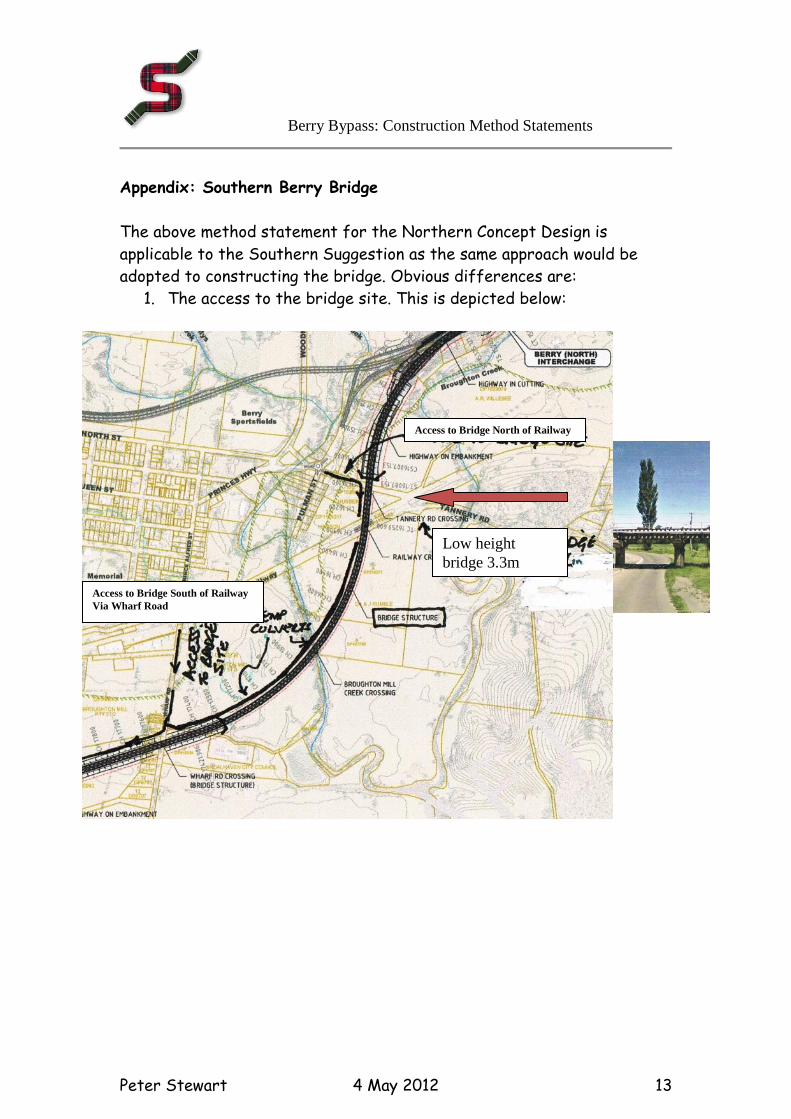
Appendix: Southern Berry Bridge
The above method statement for the Northern Concept Design is
applicable to the Southern Suggestion as the same approach would be
adopted to constructing the bridge. Obvious differences are:
1. The access to the bridge site. This is depicted below:
Access to Bridge North of Railway
Access to Bridge South of Railway
Via Wharf Road
Low height
bridge 3.3m
Princes Highway Upgrade – Gerringong to Bomaderry
Foxground and Berry Bypass
Report on preparation of route feasibility comparative cost estimates
Appendix F2
Construction methodology:
Construction method statements – bulk earthworks
Berry Bypass: Construction Method Statements
Peter Stewart 15 March 2012 1
CONSTRUCTION METHOD STATEMENT
10630 Bulk Earthworks
Northern Route
Scope:
This MS describes the approach to the bulk earthworks for the
Northern Route. The Southern suggestion is basically similar and
any changes are noted in the appendix. Major cut is in Latite and
other cuts in sandstone and stiff silty clays.
Earthworks
Mass Haul Analysis
Purpose
Earthworks are one of the most significant costs in a major road project.
A mass haul analysis aims at finding the most economic approach to
construction of the earthworks. This is best achieved by minimizing haul
distances and the quantity of imported fill (if required)
Approach
From the design long and cross sections the volumes of earthworks are
determined. These are either cuts (Excavated material) or fills
(embankments). The amount of topsoil is determined and this is generally
stockpiled for later reuse in landscaping the embankment batters. Then
the amount of unsuitable material is assessed from knowledge of the
geotechnical conditions along the route and experience. The final mass
haul then takes these factors into account in determining the earthworks
balance (where the amount of cut equals the amount of fill consistent
with the minimum of haul distance)
Constraints
Mass haul analysis takes into account material properties but also:
Berry Bypass: Construction Method Statements
Peter Stewart 15 March 2012 2
1. Geological properties of the excavated material and its suitability
for its intended use
2. Special issues such as the presence of soft soils, potential acid
sulfate soils and embankment stability all impact on the mass haul
3. Material bulking and compaction factors
4. Obstacles such as major rivers, roads, railways which intercept
the mass haul and hence impact the analysis
5. Accommodation of existing traffic by means of staging or traffic
switching
6. Need to sequence work to optimize usage of plant and to achieve
the shortest possible programme
Reference Documents
AECOM Concept Design Drawings dated 30 June 2011
Geotechnical reports as follows:
o Concept Design Report – Foxground and Berry Bypass.
Appendix A – geotechnical Report prepared by AECOM Jan
2011
o HWI – Princes Highway: proposed cutting Foxground:
Geotechnical Investigation – Overview Report prepared by
Southern Geotechnical Services, Wollongong Nov 2011
o Geotechnical Interpretive Report for Concept Design
prepared by Coffey Geotechnics May 2010
Raw mass haul for main alignment showing accumulated earthworks
volumes. The earthworks volumes on the raw diagram exclude
pavement layers, topsoil removal, rock ripping, unsuitable material
and bulking factors.
Construction Method:
Basics:
Berry Bypass: Construction Method Statements
Peter Stewart 15 March 2012 3
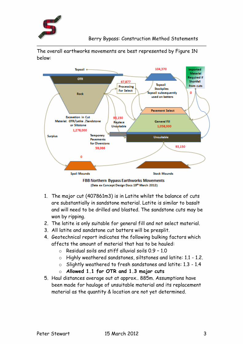
The overall earthworks movements are best represented by Figure 1N
below:
1. The major cut (407861m3) is in Latite whilst the balance of cuts
are substantially in sandstone material. Latite is similar to basalt
and will need to be drilled and blasted. The sandstone cuts may be
won by ripping.
2. The latite is only suitable for general fill and not select material.
3. All latite and sandstone cut batters will be presplit.
4. Geotechnical report indicates the following bulking factors which
affects the amount of material that has to be hauled:
o Residual soils and stiff alluvial soils 0.9 – 1.0
o Highly weathered sandstones, siltstones and latite: 1.1 - 1.2.
o Slightly weathered to fresh sandstones and latite: 1.3 - 1.4
o Allowed 1.1 for OTR and 1.3 major cuts
5. Haul distances average out at approx.. 885m. Assumptions have
been made for haulage of unsuitable material and its replacement
material as the quantity & location are not yet determined.
Berry Bypass: Construction Method Statements
Peter Stewart 15 March 2012 4
6. Short hauls say under 1.5km are generally handled with motorised
scrapers provided the material is not too abrasive. Latite is
abrasive and generally unsuitable for scraper work.
7. As the latite is quite abrasive the rock is loaded into haul trucks
and transported to the embankment fills. Off highway trucks are
used where possible eg on ‘greenfield’ sites and in the first stage
of the staged works.
8. Highway trucks have to be used where material is required to
transported on public roads and this also applies to the second
stage of the staged works.
9. Where staged works are necessary in order to accommodate the
existing traffic flows on the Princes highway it has been assumed
that 60% of the works can be executed in the first stage and 40%
in the second stage.
10. In order to accommodate construction the existing highway will
require a number of temporary diversions and cross over points.
11. Cross over points would be located at Chainages 11950, 13800,
14250 & 15400
12. Some material, mainly sandstone, is suitable for pavement material
in the Select Material Zone. Provided this material is not required
in embankments it will be hauled to the proposed site of the truck
rest stop and processed there for use as select material.
References (approximate):
Cut / Fill reference Start
Chainage Finish
Chainage
C1 7600 7600
F3 7600 8000
C2 8000 8400
F4 side 8400 8470
C3 8470 9380
F5 side 9000 9100
F6a 9380 9910
Broughton Ck Bridge 1 9910 10030
F6b 10030 10060
F7 10060 10670
Broughton Ck Bridge 2 10670 10760
F7b 10760 11120
Broughton Ck Bridge 3 11120 11320
F7c 11320 11360
Berry Bypass: Construction Method Statements
Peter Stewart 15 March 2012 5
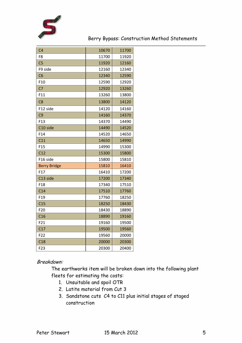
C4 10670 11700
F8 11700 11920
C5 11920 12160
F9 side 12160 12340
C6 12340 12590
F10 12590 12920
C7 12920 13260
F11 13260 13800
C8 13800 14120
F12 side 14120 14160
C9 14160 14370
F13 14370 14490
C10 side 14490 14520
F14 14520 14650
C11 14650 14990
F15 14990 15300
C12 15300 15800
F16 side 15800 15810
Berry Bridge 15810 16410
F17 16410 17200
C13 side 17200 17340
F18 17340 17510
C14 17510 17760
F19 17760 18250
C15 18250 18430
F20 18430 18890
C16 18890 19160
F21 19160 19500
C17 19500 19560
F22 19560 20000
C18 20000 20300
F23 20300 20400
Breakdown:
The earthworks item will be broken down into the following plant
fleets for estimating the costs:
1. Unsuitable and spoil OTR
2. Latite material from Cut 3
3. Sandstone cuts C4 to C11 plus initial stages of staged
construction
Berry Bypass: Construction Method Statements
Peter Stewart 15 March 2012 6
4. Sandstone cuts C4 to C11 plus final stages of staged
construction
5. Sandstone cuts C12 to C13
6. OTR and Siltstone cuttings C14 to C18 plus initial stages of
staged construction
7. OTR and Siltstone cuttings C14 to C18 plus final stages of
staged construction
8. Ripping base of cuts
9. Construction of diversions/temporary roads
10. Zone diagram showing possible contracting approach
11. Traffic Sequencing for Staged Construction
1: Unsuitable and spoil OTR
The quantity is assumed at this stage and the assumption is made
that unsuitable will occur under embankment fills, in gullies and flood
plains. Issue is whether material can be modified to be useable or
whether it has to be disposed of. Typically this would be removed by
scraper fleet as per above, however depends on location of spoil dump and
haul route and distance. Assumed haul by truck and dog as need to haul
over public roads.
Excavate with CAT E35 excavator
Haul with truck and dog(6 no)
CAT D6H Dozer
Truck Water cart 30kL
Spotter
Anticipated Production Rates:
Production 230m3/hr
50% allowed in stock bunds with nominal compaction
50% to stockpile with no compaction
Stockpile/Bund fleet:
CAT D6S Dozer
Spotter
CAT E35 Excavator
Truck Water cart 30kL
Berry Bypass: Construction Method Statements
Peter Stewart 15 March 2012 7
2: Latite material from Cut 3 ROCK
Drill & Blast will be undertaken by a specialist subcontractor. Drill
patterns, spacing of holes, charges etc. to be provided by s/c.
Batters have to be presplit.
Anticipated Resources to carryout Construction Stage:
Subcontractor
Anticipated Production Rates: Assume blasting 10,000m3/blast
No of blasts: ~40 with a blast every 3 days
Cut would take 40*3=120 days (say 6 months)
Anticipated Resources to carryout Construction Stage:
Load dump trucks with Komatsu PC1000 excavator or equivalent
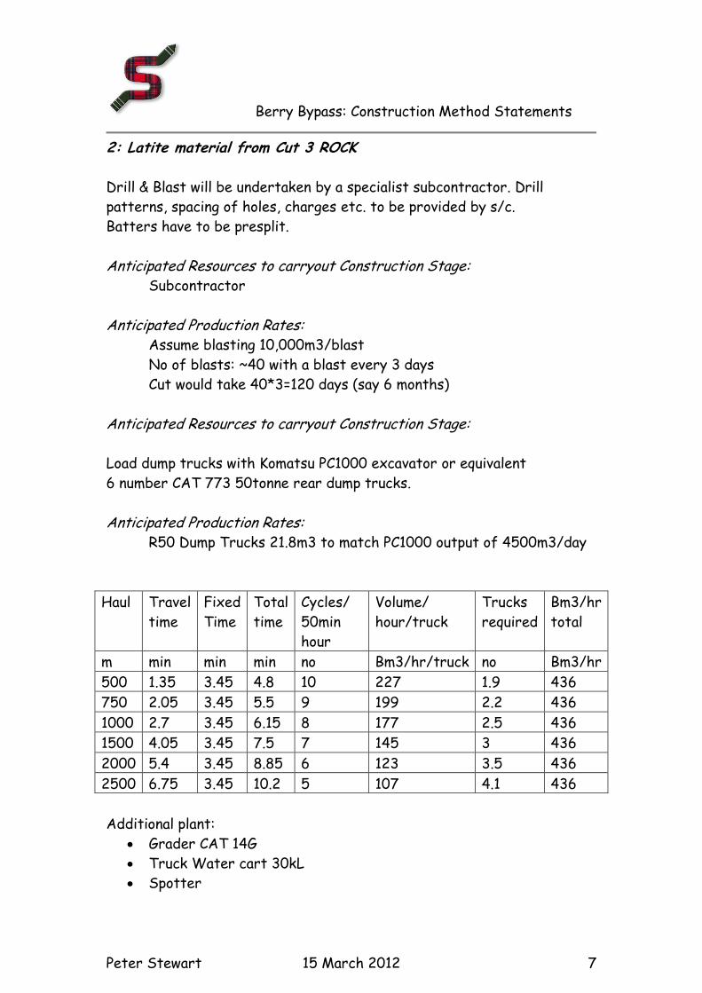
6 number CAT 773 50tonne rear dump trucks. Anticipated Production Rates:
R50 Dump Trucks 21.8m3 to match PC1000 output of 4500m3/day
Haul Travel
time
Fixed
Time
Total
time
Cycles/
50min
hour
Volume/
hour/truck
Trucks
required
Bm3/hr
total
m min min min no Bm3/hr/truck no Bm3/hr
500 1.35 3.45 4.8 10 227 1.9 436
750 2.05 3.45 5.5 9 199 2.2 436
1000 2.7 3.45 6.15 8 177 2.5 436
1500 4.05 3.45 7.5 7 145 3 436
2000 5.4 3.45 8.85 6 123 3.5 436
2500 6.75 3.45 10.2 5 107 4.1 436
Additional plant:
Grader CAT 14G
Truck Water cart 30kL
Spotter
Berry Bypass: Construction Method Statements
Peter Stewart 15 March 2012 8
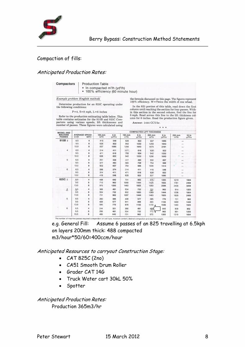
Compaction of fills:
Anticipated Production Rates:
e.g. General Fill: Assume 6 passes of an 825 travelling at 6.5kph
on layers 200mm thick: 488 compacted
m3/hour*50/60=400ccm/hour
Anticipated Resources to carryout Construction Stage: CAT 825C (2no)
CA51 Smooth Drum Roller
Grader CAT 14G
Truck Water cart 30kL 50%
Spotter
Anticipated Production Rates: Production 365m3/hr
Berry Bypass: Construction Method Statements
Peter Stewart 15 March 2012 9
3: Sandstone cuts C4 to C11 plus initial stages of staged construction
Expect to be able to rip the sandstone to win the material for general fill
and also for select material
Anticipated Resources to carryout Construction Stage:
CAT E65 Excavator
CAT D10R ripping
CAT 773 Dry (5 no)
Grader CAT 14G
Truck Water cart 30kL 50%
Spotter
Same compaction fleet as above
Anticipated Production Rates: Production 365m3/hr
4: Sandstone cuts C4 to C11 plus final stages of staged construction
Same fleet as for initial stage but with smaller water cart
Same compaction fleet as above
Anticipated Production Rates: Production 230m3/hr
5: Sandstone cuts C12 to C13 to Bridge Embankment
Expect to be able to rip the sandstone to win the material for general fill
and also for select material
Anticipated Resources to carryout Construction Stage: CAT E65 Excavator
CAT D10R ripping
CAT 773 Dry (8 no)
Grader CAT 14G
Truck Water cart 30kL 50%
Spotter
Same compaction fleet as above
Berry Bypass: Construction Method Statements
Peter Stewart 15 March 2012 10
Anticipated Production Rates: Production 365m3/hr
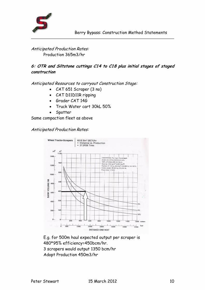
6: OTR and Siltstone cuttings C14 to C18 plus initial stages of staged construction
Anticipated Resources to carryout Construction Stage: CAT 651 Scraper (3 no)
CAT D11D11R ripping
Grader CAT 14G
Truck Water cart 30kL 50%
Spotter
Same compaction fleet as above
Anticipated Production Rates:
E.g. for 500m haul expected output per scraper is
480*95% efficiency=450bcm/hr.
3 scrapers would output 1350 bcm/hr
Adopt Production 450m3/hr
Berry Bypass: Construction Method Statements
Peter Stewart 15 March 2012 11
7: OTR and Siltstone cuttings C14 to C18 plus final stages of staged construction Anticipated Resources to carryout Construction Stage:
Excavate with CAT E35 excavator
CAT D10R Dozer ripping
Haul with truck and dog(4 no)
Truck Water cart 15kL 50%
Spotter
Same compaction fleet as above
Anticipated Production Rates: Production 230m3/hr
8: Ripping of cutting floors Anticipated Resources to carryout Construction Stage:
CAT D10R Dozer ripping
Truck Water cart 30kL 50%
Spotter
Anticipated Production Rates: Production 300m2/hr for a 300mm depth
9: Temporary Diversions
Construction of side tracks:
The tracks are to be designed to the construction travel speed
horizontally and vertically. Normally at the start of project we have an
80km/hr standard and can go down to 40km/hr. This is project specific
the appropriate radii should be adopted.
The overall cross section width of 10m should be sufficient 1.5m
shoulders and two 3.5m lanes.
Pavement specifications - a typical pavement for the side track (used on
the Conjola Mountain project on the Princes Highway) was:
Berry Bypass: Construction Method Statements
Peter Stewart 15 March 2012 12
Select material 300mm (150mm lime stabilised 3% - 150mm min
CBR 15%)
DGB 20 200mm
10mm sprayed seal
50mm Asphalt
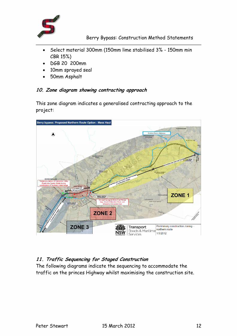
10. Zone diagram showing contracting approach This zone diagram indicates a generalised contracting approach to the
project:
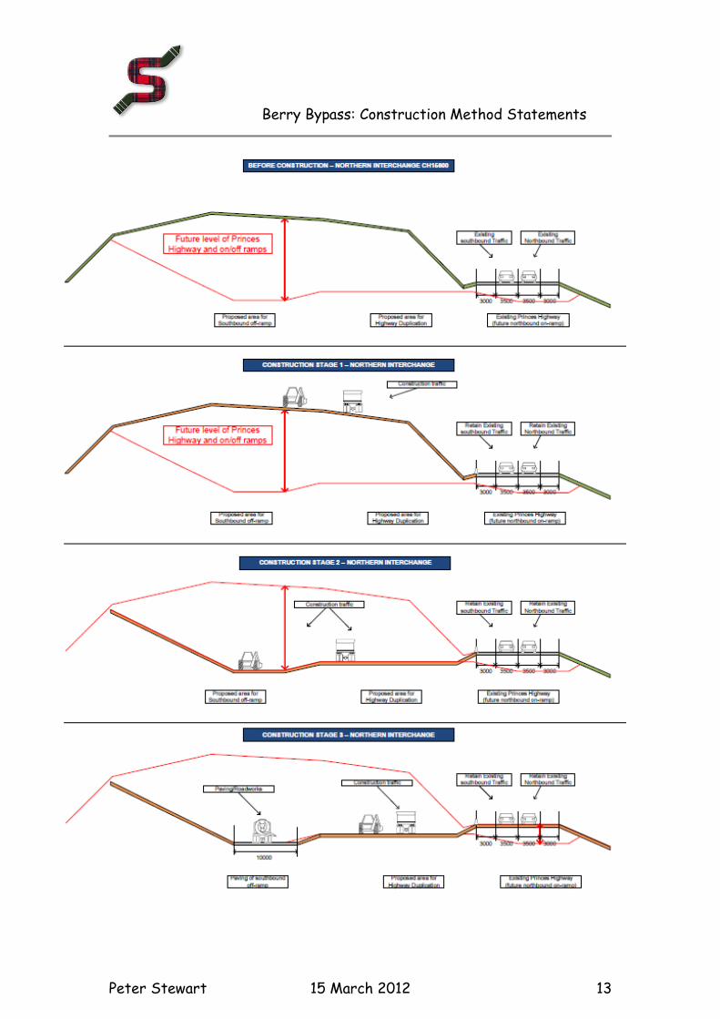
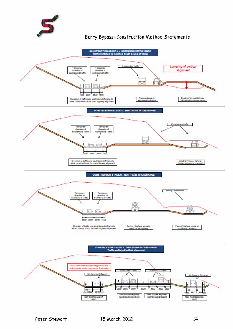
11. Traffic Sequencing for Staged Construction The following diagrams indicate the sequencing to accommodate the
traffic on the princes Highway whilst maximising the construction site.
Berry Bypass: Construction Method Statements
Peter Stewart 15 March 2012 13
Berry Bypass: Construction Method Statements
Peter Stewart 15 March 2012 14
Berry Bypass: Construction Method Statements
Peter Stewart 15 March 2012 15
Appendix for Southern Suggestion Base Case Option
In general the above approach and plant fleets apply to the Southern suggestion.
The earthworks from chainage 7600 to 14500 remains the same as for the
Northern Concept Design. Thereafter the alignment changes which impacts the
mass haul. The following are the aspects that change:
The level of documentation is not as detailed as the concept design as it is
being developed for this process. Documents adopted for the earthworks
mass haul include:
a. AECOM General Arrangement drawing SK001
b. AECOM Drawings Long sections (SK004) and cross sections March
2012
c. Raw Mass Haul ex AECOM 8th March 2012
d. Geotechnical info pending Site Investigation interpretation results
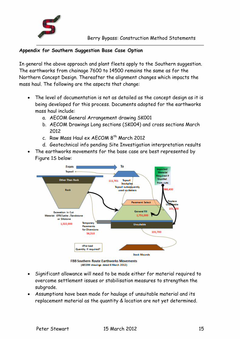
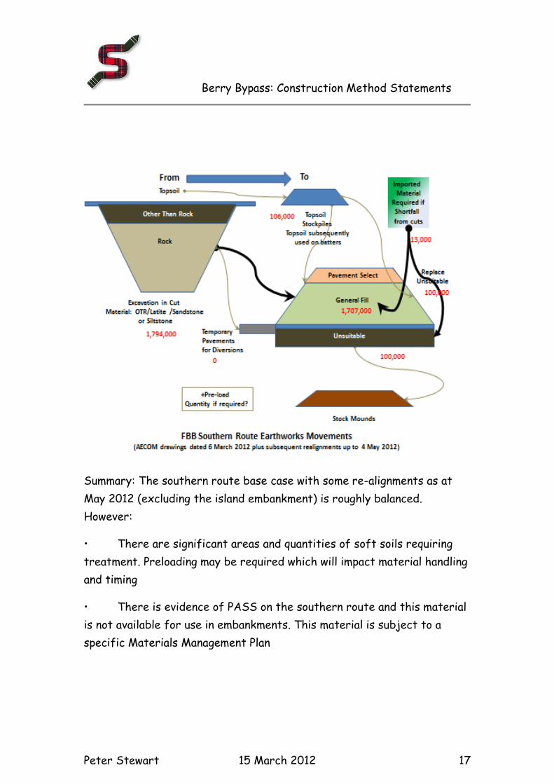
The earthworks movements for the base case are best represented by
Figure 1S below:
Significant allowance will need to be made either for material required to
overcome settlement issues or stabilisation measures to strengthen the
subgrade.
Assumptions have been made for haulage of unsuitable material and its
replacement material as the quantity & location are not yet determined.
Berry Bypass: Construction Method Statements
Peter Stewart 15 March 2012 16
Assumptions have also been made in regard to the source of the approx..
600,000m3 of fill required to make up the shortfall required for the
Southern Suggestion. Initially imported material sources were not
identified for the base case and the assumption is that material should be
available from a 10km radius.
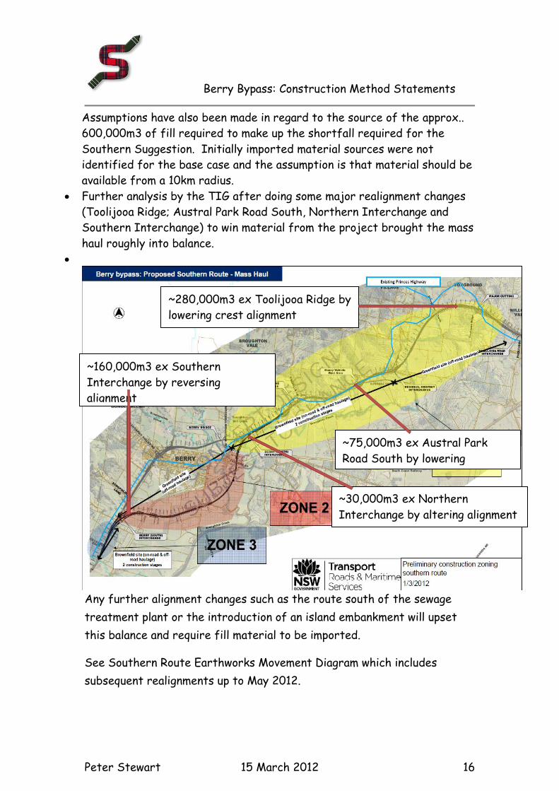
Further analysis by the TIG after doing some major realignment changes
(Toolijooa Ridge; Austral Park Road South, Northern Interchange and
Southern Interchange) to win material from the project brought the mass
haul roughly into balance.
Any further alignment changes such as the route south of the sewage
treatment plant or the introduction of an island embankment will upset
this balance and require fill material to be imported.
See Southern Route Earthworks Movement Diagram which includes
subsequent realignments up to May 2012.
~280,000m3 ex Toolijooa Ridge by
lowering crest alignment
~75,000m3 ex Austral Park
Road South by lowering
alignment
~30,000m3 ex Northern
Interchange by altering alignment
~160,000m3 ex Southern
Interchange by reversing
alignment
Berry Bypass: Construction Method Statements
Peter Stewart 15 March 2012 17
Summary: The southern route base case with some re-alignments as at
May 2012 (excluding the island embankment) is roughly balanced.
However:
• There are significant areas and quantities of soft soils requiring
treatment. Preloading may be required which will impact material handling
and timing
• There is evidence of PASS on the southern route and this material
is not available for use in embankments. This material is subject to a
specific Materials Management Plan
Berry Bypass: Construction Method Statements
Peter Stewart 15 March 2012 18
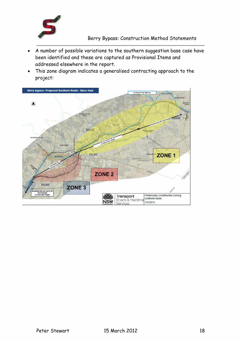
A number of possible variations to the southern suggestion base case have
been identified and these are captured as Provisional Items and
addressed elsewhere in the report.
This zone diagram indicates a generalised contracting approach to the
project: