Embed Size (px)
Citation preview

Foxboro Differential Pressure Pneumatic Transmitters
Series 13, 13A, 13H, and 15
Type
REFERENCE Document No.
6-CVT-513 Rev/Mod
G-3 Relea08
11/07/2018 Page
1 of 19
Tank Farm Maintenance Procedure CALIBRATION
USQ # Routine Maintenance
CHANGE HISTORY ( LAST 5 REV-MODS )
Rev-Mod Release Date Justification: Summary of Changes
G-3 11/07/2018 Maintenance Request Added Radiation and Contamination Control, Added new
Figure(s), Added Attachment.
G-2 03/08/2018 Maintenance Request
Deleted Steps 5.1.3, and 5.2.2, Added Steps above 5.1.4 and
5.2.3 and Added If transmitter components are dirty before
Steps 5.1.6 and 5.2.5.
G-1 08/16/2017 PER 2016-2301
Added item to Section 4.1 three performance documents to
Section 4.2, New Step5.1.1 and Sub steps 5.1.1.1 and 5.1.1.2,
Attachment 1, Figure 3 and Records Section Update.
G-0 10/13/2016
Periodic review clarification to
comply with the writer’s
standard.
Added 3rd bullet @4.1, and Steps 5.1.2 & 5.2.2. Struck Steps
5.1.9 & 5.2.9. Reword Steps 5.1.8, 5.1.9, 5.1.9.3, 5.1.9.4, 5.2.8,
5.2.9.3, 5.2.9.4.
F-1 11/19/2014 CHAMPS Removal Removed reference to CHAMPS, updated records statements
and removed next periodic review date.
Table of Contents Page
1.1 Purpose ................................................................................................................................ 3
1.2 Scope ................................................................................................................................... 3
2.0 INFORMATION............................................................................................................................. 3
2.1 General Information ............................................................................................................ 3
3.0 PRECAUTIONS AND LIMITATIONS......................................................................................... 4
3.1 Radiation and Contamination Control ................................................................................ 4
3.2 Environmental Compliance ................................................................................................ 4
4.0 PREREQUISITES .......................................................................................................................... 5
4.1 Special Tools, Equipment, and Supplies............................................................................. 5
4.2 Performance Documents ..................................................................................................... 5
5.0 PROCEDURE ................................................................................................................................. 6
5.1 Transmitter without Elevation/Suppression ........................................................................ 6
5.2 Transmitter with Elevation/Suppression ............................................................................. 9
5.3 Restoration ........................................................................................................................ 11
5.4 Acceptance Criteria ........................................................................................................... 11
5.5 Review .............................................................................................................................. 11

Foxboro Differential Pressure Pneumatic Transmitters
Series 13, 13A, 13H, and 15
Type
REFERENCE Document No.
6-CVT-513 Rev/Mod
G-3 Relea08
11/07/2018 Page
2 of 19
5.6 Records ............................................................................................................................. 11
Attachment 1 Water Trap/Pressure M&TE .............................................................................................. 12
Figure 1 - Calibration Piping Arrangement .............................................................................................. 14
Figure 2 - Calibration Adjustments........................................................................................................... 15
Figure 3 – How the Trap Works ............................................................................................................... 16
Figure 4 Negative Pressure Connection .................................................................................................... 17
Figure 5 Positive Pressure Connection ..................................................................................................... 18
Attachment 2 – Calibration Instruction ..................................................................................................... 19

Foxboro Differential Pressure Pneumatic Transmitters
Series 13, 13A, 13H, and 15
Type
REFERENCE Document No.
6-CVT-513 Rev/Mod
G-3 Relea08
11/07/2018 Page
3 of 19
1.0 PURPOSE AND SCOPE
1.1 Purpose
This procedure provides a safe and uniform method for calibrating Foxboro Differential
Pressure Pneumatic Transmitters, Series 13, 13A, 13H and 15.
1.2 Scope
This procedure applies to calibrating Foxboro Differential Pressure Pneumatic
Transmitters, Series 13, 13A, 13H and 15.
2.0 INFORMATION
2.1 General Information
2.1.1 If performance of any steps in this procedure is not required for procedure
completion, indicate steps not performed by entering "N/A" in appropriate
Data Sheet signoff space and explain in COMMENTS/REMARKS section of
Data Sheet.
2.1.2 Calibration is required if the following has occurred:
The unit has been taken apart for cleaning or parts replacement
The range has been changed
The amount of elevation or depression has been changed
substantially.
2.1.3 The transmitter may be calibrated either to the English (psi) or to the metric
(Kg per sq cm) signal pressure range. The two ranges are not exactly
equivalent; therefore, the transmitter must be calibrated to the same signal
pressure range as the receiver with which it is used.
Foxboro Differential Pressure Pneumatic Transmitters
Series 13, 13A, 13H, and 15
Type
REFERENCE Document No.
6-CVT-513 Rev/Mod
G-3 Relea08
11/07/2018 Page
4 of 19
3.0 PRECAUTIONS AND LIMITATIONS
3.1 Radiation and Contamination Control
3.1.1 Work in radiological areas will be performed using a Radiological Work
Permit following review by Radiological Control per ALARA work planning
procedure TFC-ESHQ-RP_RWP-C-03.
3.1.2 When disconnecting equipment from potentially contaminated systems or
breaking open potentially contaminated lines:
Continuous HPT coverage is required
A damp rag will be used to contain the breach until radiological
verifications have been performed
Special care shall be taken to ensure contamination control is
maintained.
3.1.3 When work is performed in or when work will result in a high contamination,
high radiation, or an airborne radioactivity area, then an approved work
package must be developed which is reviewed by Radiological Control per
the ALARA Work Planning Procedure TFC-ESHQ-RP_RWP-C-03,
(ALARA Work Planning). Any changes in the work package or this
procedure that affects radiological aspects of the work must be approved by
the appropriate project Radiological Control Organization.
3.2 Environmental Compliance
3.2.1 When working on potentially contaminated ventilation systems/equipment:
Equipment with removable contamination and/or work with
removable contamination will be contained per the latest revision of
the Containment Selection guide, Attachment A, in TFC-ESHQ-
RP_RWP-C-02
Pre and post job surveys (smears) shall be taken.

Foxboro Differential Pressure Pneumatic Transmitters
Series 13, 13A, 13H, and 15
Type
REFERENCE Document No.
6-CVT-513 Rev/Mod
G-3 Relea08
11/07/2018 Page
5 of 19
4.0 PREREQUISITES
4.1 Special Tools, Equipment, and Supplies
The following supplies may be needed to perform this procedure:
Calibrated pressure source
Test Pressure Gauge with appropriate range
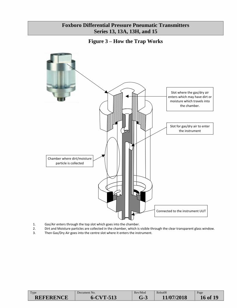
Water trap device (Figure 3)
Other tools, equipment and supplies as identified by
Shift Manager/OE/FWS/User.
4.2 Performance Documents
The following documents may be needed during the performance of this procedure:
Vendor Information No. 14020 and 1525 and Instrument books 2556 or 2558
Radiological survey plan
Waste planning checklist
Pressure M&TE vendor manual.

Foxboro Differential Pressure Pneumatic Transmitters
Series 13, 13A, 13H, and 15
Type
REFERENCE Document No.
6-CVT-513 Rev/Mod
G-3 Relea08
11/07/2018 Page
6 of 19
5.0 PROCEDURE
NOTE - This calibration may be performed in-place or in the shop.
- This procedure is written for direct acting units. For units which are set up to be
reverse acting, switch the words minimum to maximum and maximum to minimum
throughout procedure.
- Depending on the type of transmitter (with or without Elevation/Suppression) Sections
within this procedure may be performed independently or not at all.
5.1 Transmitter without Elevation/Suppression
5.1.1 IF performing this procedure on a system that has the potential for free
liquids or moisture to enter the Pressure M&TE, USE a water trap device.
5.1.1.1 ENSURE the Water Trap is installed in a vertical position to
operate correctly. (Figure 3)
5.1.1.2 IF liquids or moisture gets into the Water Trap or Pressure
M&TE REFER to Attachment 1.
5.1.2 IF performing this procedure on a system that is potentially contaminated,
FOLLOW Calibration Instructions. (Attachment 2)
5.1.3 VALVE transmitter out of service.
5.1.4 CONNECT test equipment to transmitter (per Figure 1).
5.1.5 APPLY test input values as specified per Data Sheet AND
RECORD the corresponding output in the As-Found section of the
Data Sheet.
5.1.6 IF values are within tolerance per Data Sheet, RECORD output values in the
As-Left section of the Data Sheet AND
GO TO Section 5.3 Restoration.
5.1.7 IF transmitter components are dirty, CLEAN the following transmitter
components per the applicable Foxboro Instruction Book 2556 or 2558:
Screen Filter
Restrictor
Nozzle Assembly.

Foxboro Differential Pressure Pneumatic Transmitters
Series 13, 13A, 13H, and 15
Type
REFERENCE Document No.
6-CVT-513 Rev/Mod
G-3 Relea08
11/07/2018 Page
7 of 19
5.1 Transmitter without Elevation/Suppression (Cont.)
5.1.8 IF the transmitter shows signs of hysteresis and/or slow response,
PERFORM the following:
5.1.8.1 REMOVE Control Relay.
5.1.8.2 CLEAN AND CALIBRATE Control Relay per the applicable
Foxboro Instruction Book 2556 or 2558.
5.1.8.3 REPLACE Control Relay.
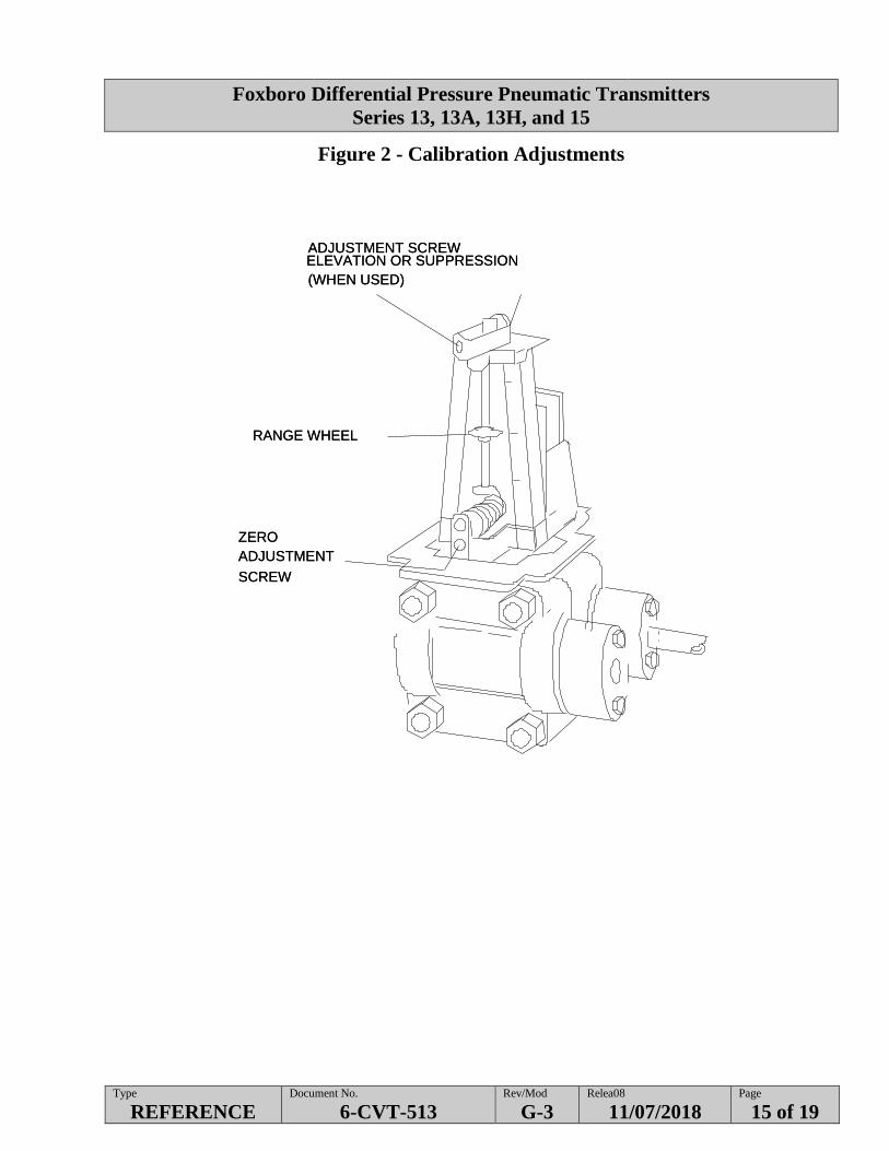
NOTE - See Figure 2 for zero adjustment screw location.
5.1.9 APPLY minimum value per Data Sheet AND
ADJUST zero screw so that output pressure reads minimum output value
specified per Data Sheet.
NOTE - Raising range wheel will lower output reading (see Figure 2).
5.1.10 APPLY maximum value specified per Data Sheet. AND
ADJUST range wheel so that output pressure reads maximum output value at
desired accuracy specified per Data Sheet.
OR
IF instrument does not respond to further adjustments, REPEAT Steps 5.1.9
and 5.1.10.
5.1.11 IF it is determined the transmitter should be replaced:
5.1.11.1 INITIATE a BOM.
5.1.11.2 OBTAIN new transmitter.
5.1.11.3 PERFORM bench test by repeating Steps 5.1.9 and 5.1.10,
UNTIL the desired accuracy is obtained.
5.1.11.4 INSTALL transmitter at field location AND
PERFORM the following:
RE-INSTALL mounting bolts
RE- CONNECT tubing with Test Equipment setup.
Foxboro Differential Pressure Pneumatic Transmitters
Series 13, 13A, 13H, and 15
Type
REFERENCE Document No.
6-CVT-513 Rev/Mod
G-3 Relea08
11/07/2018 Page
8 of 19
5.1 Transmitter without Elevation/Suppression (Cont.)
5.1.12 APPLY test input values as specified per Data Sheet AND
CHECK output values for tolerance.
5.1.13 IF values are within tolerance per Data Sheet, RECORD output values in the
As-Left section of the Data Sheet AND
GO TO Section 5.3 Restoration.
5.1.14 IF values are not within tolerance per Data Sheet, REPEAT Steps 5.1.9 and
5.1.10 until values are within tolerance,
OR
IF values cannot be brought into tolerance, NOTIFY FWS for resolution
AND
STOP WORK.

Foxboro Differential Pressure Pneumatic Transmitters
Series 13, 13A, 13H, and 15
Type
REFERENCE Document No.
6-CVT-513 Rev/Mod
G-3 Relea08
11/07/2018 Page
9 of 19
5.2 Transmitter with Elevation/Suppression
5.2.1 VALVE transmitter out of service.
5.2.2 CONNECT test equipment to transmitter (per Figure 1).
5.2.3 APPLY each test input value as specified per Data Sheet AND
RECORD the corresponding output in the As-Found section of the Data
Sheet.
5.2.4 IF values are within tolerance per Data Sheet, RECORD output values in the
As-Left section of the Data Sheet AND
GO TO Section 5.3 Restoration.
5.2.5 IF transmitter components are dirty, CLEAN the following transmitter
components per the applicable Foxboro Instruction Book 2556 or 2558:
Screen Filter
Restrictor
Nozzle Assembly.
5.2.6 IF the transmitter shows signs of hysteresis and/or slow response,
PERFORM the following:
5.2.6.1 REMOVE Control Relay.
5.2.6.2 CLEAN AND CALIBRATE Control Relay per the applicable
Foxboro Instruction Book 2556 or 2558.
5.2.6.3 REPLACE Control Relay.
NOTE - Coarse adjustments are made with the elevation adjustment screw and fine
adjustments are made with the zero adjustment screw (see Figure 2).
5.2.7 APPLY minimum value specified per Data Sheet AND
ADJUST the output to read the minimum value specified per Data Sheet.
Foxboro Differential Pressure Pneumatic Transmitters
Series 13, 13A, 13H, and 15
Type
REFERENCE Document No.
6-CVT-513 Rev/Mod
G-3 Relea08
11/07/2018 Page
10 of 19
5.2 Transmitter with Elevation/Suppression (Cont.)
NOTE - Raising the range adjusting wheel will lower the output (see Figure 2).
5.2.8 APPLY differential pressure corresponding to maximum value specified per
Data Sheet AND
ADJUST range wheel until the output reads the maximum value at desired
accuracy specified per Data Sheet.
OR
IF instrument does not respond to further adjustments, REPEAT Steps 5.2.7
and 5.2.8.
5.2.9 IF it is determined the transmitter should be replaced:
5.2.9.1 INITIATE a BOM.
5.2.9.2 OBTAIN new transmitter.
5.2.9.3 PERFORM bench test by repeating Steps 5.2.7 and 5.2.8,
UNTIL the desired accuracy is obtained.
5.2.9.4 INSTALL transmitter at field location AND
PERORM the following:
RE-INSTALL mounting bolts
RE- CONNECT tubing with Test Equipment setup.
5.2.10 APPLY test input values as specified per Data Sheet AND
CHECK output values for tolerance.
5.2.11 IF values are within tolerance per Data Sheet, RECORD output values in the
As-Left section of the Data Sheet AND
GO TO Section 5.3 Restoration.
5.2.12 IF values aren’t in tolerance per Data Sheet, REPEAT Steps 5.2.7 and 5.2.8,
OR
IF values cannot be brought into tolerance, NOTIFY FWS for resolution
AND
STOP WORK.
Foxboro Differential Pressure Pneumatic Transmitters
Series 13, 13A, 13H, and 15
Type
REFERENCE Document No.
6-CVT-513 Rev/Mod
G-3 Relea08
11/07/2018 Page
11 of 19
5.3 Restoration
5.3.1 IF any problems were encountered with calibration, INFORM FWS.
5.3.2 ENSURE Test Equipment has been disconnected and removed.
5.3.3 ENSURE Test Equipment information and calibration status are recorded on
Data Sheet.
5.3.4 ENSURE equipment system restoration by observing indications are
consistent with expected conditions.
5.3.5 CHECK for leaks.
5.3.6 NOTIFY Operations that testing is complete and system may be returned to
desired configuration.
5.4 Acceptance Criteria
Acceptance Criteria has been met when Steps in this procedure have been satisfactorily
performed and As-Left values meet the specifications and tolerance(s) per Data Sheet.
5.5 Review
5.5.1 INFORM FWS test is complete.
5.5.2 FWS REVIEW AND ENSURE the following:
Completed Data Sheets meet the acceptance criteria.
Comments sections are filled out appropriately.
Work requests needed as a result of this procedure are identified and
generated.
Work request number(s) of any work documents generated as a result
of this procedure, are recorded in the Comments/Remarks section of
the Data Sheet.
5.6 Records
This procedure is performed within a work package, as such, the procedure in its entirety
will be maintained as a record per the Work Control process.
The record custodian identified in the Company-level Records Inventory and Disposition
Schedule (RIDS) is responsible for record retention in accordance with TFC-BSM-
IRM_DC-C-02.

Foxboro Differential Pressure Pneumatic Transmitters
Series 13, 13A, 13H, and 15
Type
REFERENCE Document No.
6-CVT-513 Rev/Mod
G-3 Relea08
11/07/2018 Page
12 of 19
Attachment 1 Water Trap/Pressure M&TE
Water Trap with Potentially Contaminated Liquid
1. If potentially contaminated liquid gets into Water Trap, Suspend the work.
2. Notify the FWS.
3. When provided approval from the FWS proceed as follows.
4. Remove Pressure M&TE from field.
5. Return to a RMA.
6. Disassemble the Water Trap.
7. Allow trap to dry overnight.
8. Survey disassembled trap components in accordance with Radcon survey plan.
9. If the Water Trap can be released, return it to tool crib.
10. If the Water Trap cannot be released, dispose of it per waste planning checklist.
Water Trap with Clean Liquid (NOT Contaminated)
1. If clean liquid gets into Water Trap, disassemble the Water Trap.
2. Allow Water Trap to dry overnight.
3. Re-assemble the Water Trap.
4. Return the Water Trap to the tool crib.

Foxboro Differential Pressure Pneumatic Transmitters
Series 13, 13A, 13H, and 15
Type
REFERENCE Document No.
6-CVT-513 Rev/Mod
G-3 Relea08
11/07/2018 Page
13 of 19
Attachment 1 – Water Trap/Pressure M&TE (Cont.)
M&TE with Potentially Contaminated Liquid
1. If potentially contaminated liquid gets past water trap and inside Pressure M&TE, Suspend the
work.
2. Notify FWS.
3. Wait for further directions.
M&TE with Clean Liquid (NOT Contaminated)
1. If clean liquid gets past the water trap disassemble and dry out Pressure M&TE per manufactures
direction.
2. Return the M&TE to the tool crib.
3. Request the M&TE to be returned to NIST calibration lab for recalibration.

Foxboro Differential Pressure Pneumatic Transmitters
Series 13, 13A, 13H, and 15
Type
REFERENCE Document No.
6-CVT-513 Rev/Mod
G-3 Relea08
11/07/2018 Page
14 of 19
Figure 1 - Calibration Piping Arrangement
BLEEDER VALVE
(needle type)
VENT
LOW PRESSURE
SIDE
AIR SUPPLY TO
HIGH PRESSURE
SIDE
AIR SUPPLY: REGULATE
TO PRESSURE AT WHICH
INSTRUMENT WILL BE
OPERATING.
CALIBRATED PRESSURE SOURCE
PRESSURE SOURCE RANGEMUST BE GREATER THANDESIRED RANGE ASSPECIFIED ON DATA SHEET
NOTE:
BLEEDER VALVE
(needle type)
VENT
LOW PRESSURE
SIDE
AIR SUPPLY TO
HIGH PRESSURE
SIDE
AIR SUPPLY: REGULATE
TO PRESSURE AT WHICH
INSTRUMENT WILL BE
OPERATING.
CALIBRATED PRESSURE SOURCE
PRESSURE SOURCE RANGEMUST BE GREATER THANDESIRED RANGE ASSPECIFIED ON DATA SHEET
NOTE:
Foxboro Differential Pressure Pneumatic Transmitters
Series 13, 13A, 13H, and 15
Type
REFERENCE Document No.
6-CVT-513 Rev/Mod
G-3 Relea08
11/07/2018 Page
15 of 19
Figure 2 - Calibration Adjustments
ADJUSTMENT SCREWELEVATION OR SUPPRESSION
(WHEN USED)
RANGE WHEEL
ZERO
ADJUSTMENT
SCREW
ADJUSTMENT SCREWELEVATION OR SUPPRESSION
(WHEN USED)
RANGE WHEEL
ZERO
ADJUSTMENT
SCREW
Foxboro Differential Pressure Pneumatic Transmitters
Series 13, 13A, 13H, and 15
Type
REFERENCE Document No.
6-CVT-513 Rev/Mod
G-3 Relea08
11/07/2018 Page
16 of 19
Figure 3 – How the Trap Works
Slot where the gas/dry air enters which may have dirt or
moisture which travels into
the chamber.
Slot for gas/dry air to enter
the instrument
Chamber where dirt/moisture
particle is collected
Connected to the instrument UUT
1. Gas/Air enters through the top slot which goes into the chamber.2. Dirt and Moisture particles are collected in the chamber, which is visible through the clear transparent glass window.3. Then Gas/Dry Air goes into the centre slot where it enters the instrument.

Foxboro Differential Pressure Pneumatic Transmitters
Series 13, 13A, 13H, and 15
Type
REFERENCE Document No.
6-CVT-513 Rev/Mod
G-3 Relea08
11/07/2018 Page
17 of 19
Figure 4 Negative Pressure Connection

Foxboro Differential Pressure Pneumatic Transmitters
Series 13, 13A, 13H, and 15
Type
REFERENCE Document No.
6-CVT-513 Rev/Mod
G-3 Relea08
11/07/2018 Page
18 of 19
Figure 5 Positive Pressure Connection

Foxboro Differential Pressure Pneumatic Transmitters
Series 13, 13A, 13H, and 15
Type
REFERENCE Document No.
6-CVT-513 Rev/Mod
G-3 Relea08
11/07/2018 Page
19 of 19
Attachment 2 – Calibration Instruction
Positive pressure calibrations:
Note: Vent Valve assembly is required on all positive pressure calibrations to ensure MT&E is not
contaminated by venting potential process air back through MT&E.
Install vent valve assembly Per Figure 5
Ensure IV is open and VV is closed
Proceed with calibration per work package
Whenever venting is required during calibration steps, vent stored pressure as follows.
NOTE- Valve IV can remain open when reading is required via M&TE.
Ensure IV valve is closed
Ensure VV valve is opened
Repeat sequence as necessary to complete the calibration.
After all steps are completed for the calibration, perform RCT survey release plan XXX
Negative pressure calibrations:
Note: use of surrogate filter is required for negative pressure calibrations to ensure MT&E is not
contaminated by pulling process air into MT&E while drawing Vacuum.
Negative calibrations should be performed as Follows.
Ensure surrogate filter holder has media installed.
Connect filter in-line per Figure 4
Ensure IV is open
Pull a representative vacuum into MT&E through filter
Ensure IV is closed
Vent through VV
RCT to perform survey of the media.
IF no contamination found remove surrogate filter holder/manifold and proceed with calibration.


![[MI 020-602] Foxboro® Pressure S Series Transmitters ... 020-602... · Instruction MI 020-602 January 2015 Foxboro® Pressure S Series Transmitters IDP10S Differential Pressure Transmitter](https://img.dokumen.tips/doc/110x75/5b3b467d7f8b9ace408c80e7/mi-020-602-foxboro-pressure-s-series-transmitters-020-602-instruction.jpg)


![[MI 020-602] Foxboro® Pressure S Series Transmitters ... 020-602 IDP10S.pdfInstruction MI 020-602 January 2015 Foxboro® Pressure S Series Transmitters IDP10S Differential Pressure](https://img.dokumen.tips/doc/110x75/60eb709c413ac071ea1855e1/mi-020-602-foxboro-pressure-s-series-transmitters-020-602-idp10spdf-instruction.jpg)


![[MI 020-601] Foxboro S Series Pressure …cth.ca/wp-content/uploads/2017/11/mi_020-601_h.pdfInstruction MI 020-601 September 2017 Foxboro® S Series Pressure Transmitters IAP10S Absolute](https://img.dokumen.tips/doc/110x75/5e96b2b0daabb7357b31f826/mi-020-601-foxboro-s-series-pressure-cthcawp-contentuploads201711mi020-601hpdf.jpg)