Embed Size (px)
Citation preview
© 2012 The McGraw-Hill Companies, Inc. All rights reserved
Mike Meyers’ CompTIA A+®
Guide to
Managing and
Troubleshooting PCs
Fourth Edition
Local Area NetworkingChapter 22

© 2012 The McGraw-Hill Companies, Inc. All rights reserved
Mike Meyers’ CompTIA A+®
Guide to
Managing and
Troubleshooting PCs
Fourth Edition
Overview
• In this chapter, you will learn how to
– Install and troubleshoot structured cabling
– Explain the basics of TCP/IP
– Install and configure wired networks
– Troubleshoot wired networks

© 2012 The McGraw-Hill Companies, Inc. All rights reserved
Mike Meyers’ CompTIA A+®
Guide to
Managing and
Troubleshooting PCs
Fourth Edition
Beyond Basic Ethernet Cabling

© 2012 The McGraw-Hill Companies, Inc. All rights reserved
Mike Meyers’ CompTIA A+®
Guide to
Managing and
Troubleshooting PCs
Fourth Edition
Alternative Connections
• Ethernet is the dominant networking technology, and unshielded twisted-pair (UTP) wired Ethernet networks using RJ-45 connectors are the most dominant form of Ethernet—but other cabling types include fiber optic cabling and coaxial cable.

© 2012 The McGraw-Hill Companies, Inc. All rights reserved
Mike Meyers’ CompTIA A+®
Guide to
Managing and
Troubleshooting PCs
Fourth Edition
Alternative Connections (continued)
• Fiber Optic
– Uses light instead of electricity
– Immune to electrical problems such as lightning,
short circuits, and static
– Fiber optic signals travel much farther—2000 meters or more.
– Most fiber Ethernet networks use 62.5/125
multimode fiber optic cable, which requires two cables.
– Three of the more common connectors used in fiber optic networks are SC, ST, and LC/MT-RJ.

© 2012 The McGraw-Hill Companies, Inc. All rights reserved
Mike Meyers’ CompTIA A+®
Guide to
Managing and
Troubleshooting PCs
Fourth Edition
Alternative Connections (continued)
Figure 1: Typical fiber optic cables with connectors
Figure 1: Typical fiber optic cables with connectors
© 2012 The McGraw-Hill Companies, Inc. All rights reserved
Mike Meyers’ CompTIA A+®
Guide to
Managing and
Troubleshooting PCs
Fourth Edition
Alternative Connections (continued)
• Fiber Optic (continued)
– Multimode fiber uses LEDs and transmits multiple light signals at the same time, each using a
different reflection angle within the core of the cable. The multiple reflection angles tend to disperse over long distances, so multimode fiber optic cables are used for relatively short distances
(~600m). It is also slower (10, 100, or 1000 Mbps).
– Single-mode fiber optic cable uses laser light and is used for high transfer rates over long distances.

© 2012 The McGraw-Hill Companies, Inc. All rights reserved
Mike Meyers’ CompTIA A+®
Guide to
Managing and
Troubleshooting PCs
Fourth Edition
Alternative Connections (continued)
• Fiber Optic (continued)
– The major differences in fiber standards are the speed and distance limitations and the way they
interconnect.
– You must use matching fiber switches, cards, and connectors.

© 2012 The McGraw-Hill Companies, Inc. All rights reserved
Mike Meyers’ CompTIA A+®
Guide to
Managing and
Troubleshooting PCs
Fourth Edition
Alternative Connections (continued)
• Coax/BNC
– Early versions of Ethernet ran on coaxial cable instead of UTP.
– Primarily used now for cable modems and satellite connections.
– Coax cable consists of a center cable (core) surrounded by insulation. This in turn is covered
with a shield of braided cable. The center core actually carries the signal. The shield effectively eliminates outside interference. The entire cable is then surrounded by a protective insulating cover.

© 2012 The McGraw-Hill Companies, Inc. All rights reserved
Mike Meyers’ CompTIA A+®
Guide to
Managing and
Troubleshooting PCs
Fourth Edition
Alternative Connections (continued)
Figure 1: Typical fiber optic cables with connectors
Figure 2: Typical coax

© 2012 The McGraw-Hill Companies, Inc. All rights reserved
Mike Meyers’ CompTIA A+®
Guide to
Managing and
Troubleshooting PCs
Fourth Edition
Alternative Connections (continued)
• Coax/BNC (continued)
– Coax cables are rated using an RG name, primarily RG-59 and RG-6.
– Coax standards are rated by impedance, which is measured in ohms—both RG-6 and RG-59 have a 75-ohm impedance.
– Coax most commonly uses two different types of
connectors. A BNC connector uses a quarter-twist connector, and an F-type connector uses a screw connector. BNC is uncommon, but F-type is on the back of all cable modems and most televisions.

© 2012 The McGraw-Hill Companies, Inc. All rights reserved
Mike Meyers’ CompTIA A+®
Guide to
Managing and
Troubleshooting PCs
Fourth Edition
Alternative Connections (continued)
Figure 1: Typical fiber optic cables with connectors
Figure 3: BNC connector

© 2012 The McGraw-Hill Companies, Inc. All rights reserved
Mike Meyers’ CompTIA A+®
Guide to
Managing and
Troubleshooting PCs
Fourth Edition
Alternative Connections (continued)
Figure 1: Typical fiber optic cables with connectors
Figure 4: F-type connector
© 2012 The McGraw-Hill Companies, Inc. All rights reserved
Mike Meyers’ CompTIA A+®
Guide to
Managing and
Troubleshooting PCs
Fourth Edition
Network Devices
• Hubs
– Hubs are the main interconnection for older Ethernet networks.
– Any incoming signal on any port on a hub is re-created (repeated) and sent out on every connected port on the hub.
– The downside to hubs is that all connected devices
have to share the total bandwidth.
– Hubs are extremely rare today, having been replaced by switches.

© 2012 The McGraw-Hill Companies, Inc. All rights reserved
Mike Meyers’ CompTIA A+®
Guide to
Managing and
Troubleshooting PCs
Fourth Edition
Network Devices (continued)
Figure 1: Typical fiber optic cables with connectors
Figure 5: Typical hubs

© 2012 The McGraw-Hill Companies, Inc. All rights reserved
Mike Meyers’ CompTIA A+®
Guide to
Managing and
Troubleshooting PCs
Fourth Edition
Network Devices (continued)
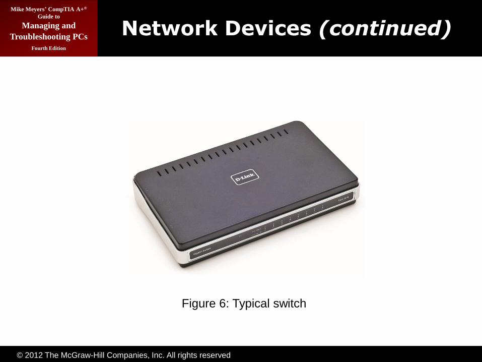
• Switches
– Switches are currently the most common interconnection for Ethernet networks.
– A switch looks like a hub, but a switch automatically creates point-to-point connections between any two computers.
– By separating every connection, each computer can
use the full bandwidth of the switch.
© 2012 The McGraw-Hill Companies, Inc. All rights reserved
Mike Meyers’ CompTIA A+®
Guide to
Managing and
Troubleshooting PCs
Fourth Edition
Network Devices (continued)
Figure 1: Typical fiber optic cables with connectors
Figure 6: Typical switch
© 2012 The McGraw-Hill Companies, Inc. All rights reserved
Mike Meyers’ CompTIA A+®
Guide to
Managing and
Troubleshooting PCs
Fourth Edition
Network Devices (continued)
• Bridges
– You can easily connect two Ethernet networks that use completely different media internally, such as
UTP to fiber or maybe UTP to wireless, using a bridge.
– A bridge will always have two interfaces, one for each of the different media.

© 2012 The McGraw-Hill Companies, Inc. All rights reserved
Mike Meyers’ CompTIA A+®
Guide to
Managing and
Troubleshooting PCs
Fourth Edition
Network Devices (continued)
Figure 1: Typical fiber optic cables with connectors
Figure 7: Typical bridge

© 2012 The McGraw-Hill Companies, Inc. All rights reserved
Mike Meyers’ CompTIA A+®
Guide to
Managing and
Troubleshooting PCs
Fourth Edition
Network Devices (continued)
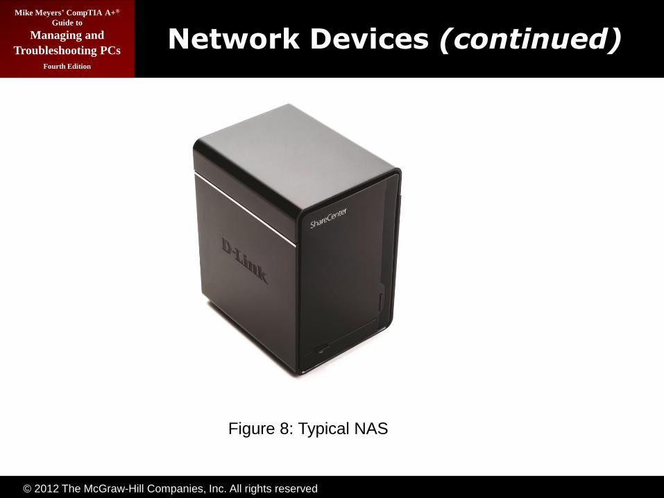
• Networked Attached Storage (NAS)
– You can use a networked attached storage (NAS) system instead of a server for file sharing across a
network.
– A NAS is basically a headless system (no monitor, no keyboard, and no mouse) that you plug into a network.
– A NAS does only one thing: share its hard drives. Almost all NAS devices use some form of Web interface for configuration, enabling you to control the NAS from a Web browser on any PC in the network.
© 2012 The McGraw-Hill Companies, Inc. All rights reserved
Mike Meyers’ CompTIA A+®
Guide to
Managing and
Troubleshooting PCs
Fourth Edition
Network Devices (continued)
Figure 1: Typical fiber optic cables with connectors
Figure 8: Typical NAS

© 2012 The McGraw-Hill Companies, Inc. All rights reserved
Mike Meyers’ CompTIA A+®
Guide to
Managing and
Troubleshooting PCs
Fourth Edition
Network Devices (continued)
• Routers
– A router connects LANs using the TCP/IP protocol.
– A router must have at least two connections—one
into a network and one out to another network. More powerful ones have many different connections.

© 2012 The McGraw-Hill Companies, Inc. All rights reserved
Mike Meyers’ CompTIA A+®
Guide to
Managing and
Troubleshooting PCs
Fourth Edition
Network Devices (continued)
Figure 1: Typical fiber optic cables with connectors
Figure 9: Typical home router

© 2012 The McGraw-Hill Companies, Inc. All rights reserved
Mike Meyers’ CompTIA A+®
Guide to
Managing and
Troubleshooting PCs
Fourth Edition
Structured Cabling
• Structured cabling standards are defined by the Telecommunications Industry Association/Electronic Industries Alliance (TIA/EIA).
– They give professional cable installers detailed specifications on every aspect of a cabled network, from the type of cabling to use to standards on
running cable in walls, even the position of wall outlets.
– The idea of structured cabling is to create a safe, reliable cabling infrastructure for all of the devices that may need interconnection.

© 2012 The McGraw-Hill Companies, Inc. All rights reserved
Mike Meyers’ CompTIA A+®
Guide to
Managing and
Troubleshooting PCs
Fourth Edition
Structured Cabling (continued)
• Cable Basics—A Star Is Born
– Most networks are typical physical star networks.
– Safety, electrical interference, and exposed cables
and equipment must be considered.
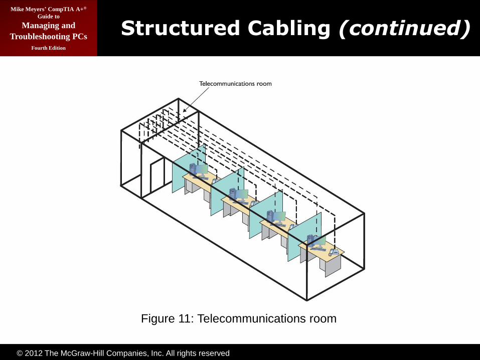
• A structured cable network requires three essential components—a telecommunications room, horizontal cabling, and a work area.
– All cables run horizontally (for the most part) from the telecommunications room to the PCs—this is called horizontal cabling.
– A single piece of installed horizontal cabling is called a run.

© 2012 The McGraw-Hill Companies, Inc. All rights reserved
Mike Meyers’ CompTIA A+®
Guide to
Managing and
Troubleshooting PCs
Fourth Edition
Structured Cabling (continued)
Figure 1: Typical fiber optic cables with connectors
Figure 10: A switch connected by UTP cable to two PCs
© 2012 The McGraw-Hill Companies, Inc. All rights reserved
Mike Meyers’ CompTIA A+®
Guide to
Managing and
Troubleshooting PCs
Fourth Edition
Structured Cabling (continued)
Figure 1: Typical fiber optic cables with connectors
Figure 11: Telecommunications room

© 2012 The McGraw-Hill Companies, Inc. All rights reserved
Mike Meyers’ CompTIA A+®
Guide to
Managing and
Troubleshooting PCs
Fourth Edition
Structured Cabling (continued)
Figure 1: Typical fiber optic cables with connectorsFigure 12: Horizontal cabling and work area

© 2012 The McGraw-Hill Companies, Inc. All rights reserved
Mike Meyers’ CompTIA A+®
Guide to
Managing and
Troubleshooting PCs
Fourth Edition
Structured Cabling (continued)
• Structured Cable Network Components (continued)
– Each of the three parts of a basic star network must follow a series of strict standards designed to ensure that the cabling system is reliable and easy to manage.
– Horizontal cabling is a CAT 5e or better UTP, but when you move into structured cabling, the TIA/EIA standards define a number of other aspects of the cable, such as the type of wires,
number of pairs of wires, and fire ratings.

© 2012 The McGraw-Hill Companies, Inc. All rights reserved
Mike Meyers’ CompTIA A+®
Guide to
Managing and
Troubleshooting PCs
Fourth Edition
Structured Cabling (continued)
• Structured Cable Network Components (continued)
– All UTP cables come in one of two types: solid core or stranded core. Each wire in solid core UTP uses a single solid wire; in stranded core each wire is actually a bundle of tiny wire strands.
– TIA/EIA specifies that horizontal cabling should always be solid core.

© 2012 The McGraw-Hill Companies, Inc. All rights reserved
Mike Meyers’ CompTIA A+®
Guide to
Managing and
Troubleshooting PCs
Fourth Edition
Structured Cabling (continued)
Figure 1: Typical fiber optic cables with connectors
Figure 13: Solid and stranded core UTP

© 2012 The McGraw-Hill Companies, Inc. All rights reserved
Mike Meyers’ CompTIA A+®
Guide to
Managing and
Troubleshooting PCs
Fourth Edition
Structured Cabling (continued)
• The Telecommunications Room
– The telecommunications room is the heart of the basic star—where all the horizontal runs from all
the work areas come together.
– The central component of every telecommunications room is one or more equipment racks, which provide a safe, stable
platform for all the different hardware components.
– All equipment racks are 19 inches wide, but they vary in height.
– You can mount almost any network hardware component into a rack, including rack-mount
servers and UPSs.

© 2012 The McGraw-Hill Companies, Inc. All rights reserved
Mike Meyers’ CompTIA A+®
Guide to
Managing and
Troubleshooting PCs
Fourth Edition
Structured Cabling (continued)
Figure 1: Typical fiber optic cables with connectors
Figure 14: A short equipment rack

© 2012 The McGraw-Hill Companies, Inc. All rights reserved
Mike Meyers’ CompTIA A+®
Guide to
Managing and
Troubleshooting PCs
Fourth Edition
Structured Cabling (continued)
Figure 1: Typical fiber optic cables with connectorsFigure 15: A floor-to-ceiling rack

© 2012 The McGraw-Hill Companies, Inc. All rights reserved
Mike Meyers’ CompTIA A+®
Guide to
Managing and
Troubleshooting PCs
Fourth Edition
Structured Cabling (continued)
Figure 1: Typical fiber optic cables with connectors
Figure 16: A rack-mounted UPS
© 2012 The McGraw-Hill Companies, Inc. All rights reserved
Mike Meyers’ CompTIA A+®
Guide to
Managing and
Troubleshooting PCs
Fourth Edition
Structured Cabling (continued)
• The Telecommunications Room (continued)
– All rack-mounted equipment uses a height measurement known simply as a U. A U is 1.75 inches. A device that fits in a 1.75-inch space is called a 1U; a device designed for a 3.5-inch space
is a 2U; and a device that goes into a 7-inch space is called a 4U. Most rack-mounted devices are 1U, 2U, or 4U.
– A patch panel is simply a box with a row of female
connectors (ports) in the front and permanent connections in the back, to which you connect the horizontal cables.
© 2012 The McGraw-Hill Companies, Inc. All rights reserved
Mike Meyers’ CompTIA A+®
Guide to
Managing and
Troubleshooting PCs
Fourth Edition
Structured Cabling (continued)
• The Telecommunications Room (continued)
– The most common type of patch panel today uses a special type of connecter called a 110 block, or sometimes a 110-punchdown block. UTP cables connect to a 110 block using a punchdown tool.
– Patch panels are used for securing, organizing, and labeling cables.
– UTP patch panels, like UTP cables, come with CAT ratings, which you should be sure to check—the
CAT rating of the patch panels must match that of the cables to which they connect.

© 2012 The McGraw-Hill Companies, Inc. All rights reserved
Mike Meyers’ CompTIA A+®
Guide to
Managing and
Troubleshooting PCs
Fourth Edition
Structured Cabling (continued)
Figure 1: Typical fiber optic cables with connectors
Figure 17: Typical patch panels

© 2012 The McGraw-Hill Companies, Inc. All rights reserved
Mike Meyers’ CompTIA A+®
Guide to
Managing and
Troubleshooting PCs
Fourth Edition
Structured Cabling (continued)
Figure 1: Typical fiber optic cables with connectors
Figure 18: Punchdown tool

© 2012 The McGraw-Hill Companies, Inc. All rights reserved
Mike Meyers’ CompTIA A+®
Guide to
Managing and
Troubleshooting PCs
Fourth Edition
Structured Cabling (continued)
Figure 1: Typical fiber optic cables with connectors
Figure 19: Punching down a 110 block

© 2012 The McGraw-Hill Companies, Inc. All rights reserved
Mike Meyers’ CompTIA A+®
Guide to
Managing and
Troubleshooting PCs
Fourth Edition
Structured Cabling (continued)
Figure 1: Typical fiber optic cables with connectors
Figure 20: Typical patch panels with labels

© 2012 The McGraw-Hill Companies, Inc. All rights reserved
Mike Meyers’ CompTIA A+®
Guide to
Managing and
Troubleshooting PCs
Fourth Edition
Structured Cabling (continued)
• The Telecommunications Room (continued)
– Once you have installed the patch panel, you need to connect the ports to the switch through patch cables. Patch cables are short (typically two- to five-foot) UTP cables.
– Although most people prefer simply to purchase premade patch cables, making your own is fairly easy—use an RJ-45 crimper and snips.
– After making your own cable, you should test it
with a cable tester.

© 2012 The McGraw-Hill Companies, Inc. All rights reserved
Mike Meyers’ CompTIA A+®
Guide to
Managing and
Troubleshooting PCs
Fourth Edition
Structured Cabling (continued)
Figure 1: Typical fiber optic cables with connectors
Figure 21: CAT level on patch panel

© 2012 The McGraw-Hill Companies, Inc. All rights reserved
Mike Meyers’ CompTIA A+®
Guide to
Managing and
Troubleshooting PCs
Fourth Edition
Structured Cabling (continued)
Figure 1: Typical fiber optic cables with connectors
Figure 22: Typical patch cable

© 2012 The McGraw-Hill Companies, Inc. All rights reserved
Mike Meyers’ CompTIA A+®
Guide to
Managing and
Troubleshooting PCs
Fourth Edition
Structured Cabling (continued)
Figure 1: Typical fiber optic cables with connectors
Figure 23: Crimper and snips

© 2012 The McGraw-Hill Companies, Inc. All rights reserved
Mike Meyers’ CompTIA A+®
Guide to
Managing and
Troubleshooting PCs
Fourth Edition
Structured Cabling (continued)
Figure 1: Typical fiber optic cables with connectors
Figure 24: Properly stripped cable

© 2012 The McGraw-Hill Companies, Inc. All rights reserved
Mike Meyers’ CompTIA A+®
Guide to
Managing and
Troubleshooting PCs
Fourth Edition
Structured Cabling (continued)
Figure 1: Typical fiber optic cables with connectors
Figure 25: Inserting the individual strands
© 2012 The McGraw-Hill Companies, Inc. All rights reserved
Mike Meyers’ CompTIA A+®
Guide to
Managing and
Troubleshooting PCs
Fourth Edition
Structured Cabling (continued)
Figure 1: Typical fiber optic cables with connectors
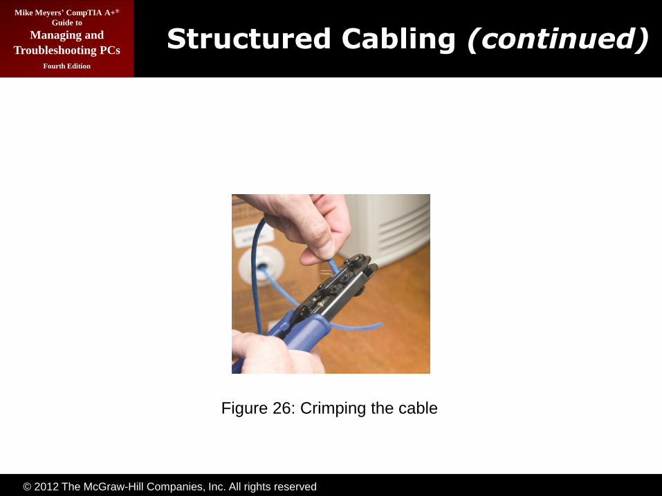
Figure 26: Crimping the cable
© 2012 The McGraw-Hill Companies, Inc. All rights reserved
Mike Meyers’ CompTIA A+®
Guide to
Managing and
Troubleshooting PCs
Fourth Edition
Structured Cabling (continued)
Figure 1: Typical fiber optic cables with connectors
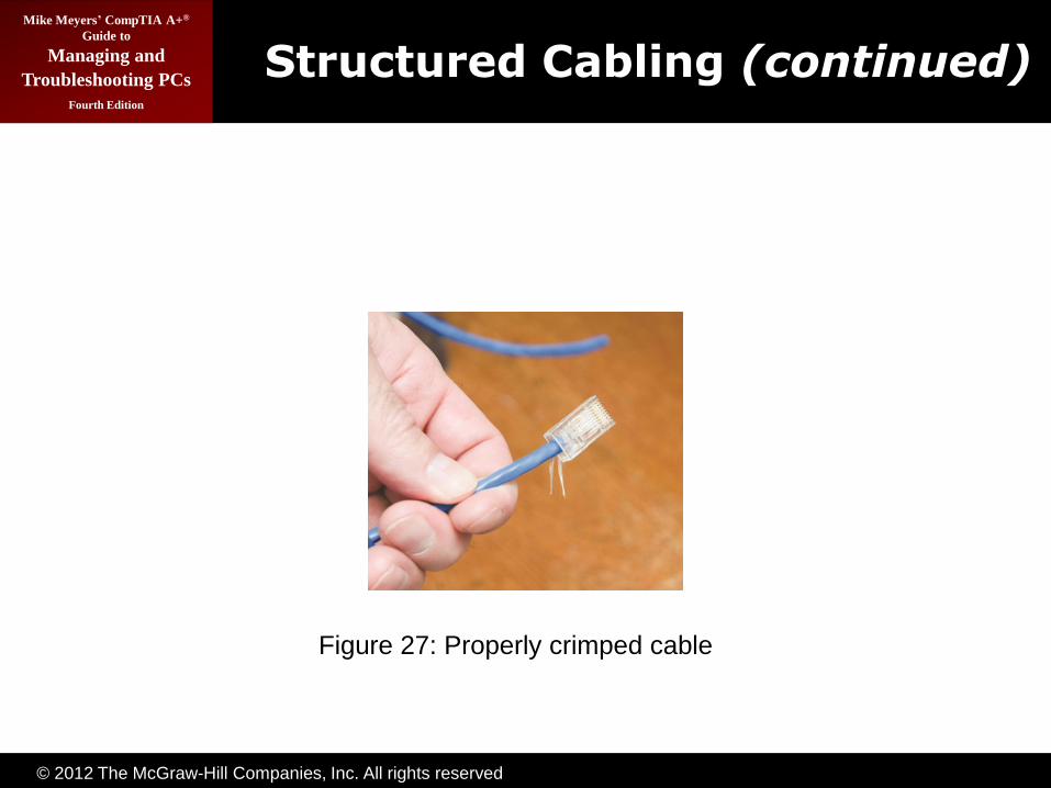
Figure 27: Properly crimped cable

© 2012 The McGraw-Hill Companies, Inc. All rights reserved
Mike Meyers’ CompTIA A+®
Guide to
Managing and
Troubleshooting PCs
Fourth Edition
Structured Cabling (continued)
Figure 1: Typical fiber optic cables with connectors
Figure 28: Adding a boot

© 2012 The McGraw-Hill Companies, Inc. All rights reserved
Mike Meyers’ CompTIA A+®
Guide to
Managing and
Troubleshooting PCs
Fourth Edition
Structured Cabling (continued)
Figure 1: Typical fiber optic cables with connectors
Figure 29: Typical tester

© 2012 The McGraw-Hill Companies, Inc. All rights reserved
Mike Meyers’ CompTIA A+®
Guide to
Managing and
Troubleshooting PCs
Fourth Edition
Structured Cabling (continued)
• The Work Area
– A work area is nothing more than a wall outlet that serves as the termination point for horizontal
network cables: a convenient insertion point for a PC and a telephone.
– A wall outlet itself consists of one or two female jacks to accept the cable, a mounting bracket, and
a faceplate. You connect the PC to the wall outlet with a patch cable.
– The female RJ-45 jacks in these wall outlets also have CAT ratings. You must buy CAT-rated jacks for wall outlets that match the CAT rating of the
cabling in your network.

© 2012 The McGraw-Hill Companies, Inc. All rights reserved
Mike Meyers’ CompTIA A+®
Guide to
Managing and
Troubleshooting PCs
Fourth Edition
Structured Cabling (continued)
Figure 1: Typical fiber optic cables with connectors
Figure 30: Typical work area outlet
© 2012 The McGraw-Hill Companies, Inc. All rights reserved
Mike Meyers’ CompTIA A+®
Guide to
Managing and
Troubleshooting PCs
Fourth Edition
Structured Cabling (continued)
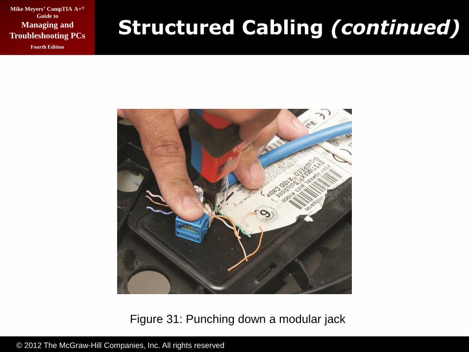
• The Work Area (continued)
– Some use the same connectors, often 110 punchdowns, in the wall outlets that they use on
the patch panels.
– The last step is connecting the PC to the wall outlet. Here again, most folks use a patch cable. Its stranded cabling stands up to the abuse caused
by moving PCs.
– The work area may be the simplest part of the structured cabling system, but it is also the source of most network failures.
© 2012 The McGraw-Hill Companies, Inc. All rights reserved
Mike Meyers’ CompTIA A+®
Guide to
Managing and
Troubleshooting PCs
Fourth Edition
Structured Cabling (continued)
Figure 1: Typical fiber optic cables with connectorsFigure 31: Punching down a modular jack

© 2012 The McGraw-Hill Companies, Inc. All rights reserved
Mike Meyers’ CompTIA A+®
Guide to
Managing and
Troubleshooting PCs
Fourth Edition
TCP/IP
© 2012 The McGraw-Hill Companies, Inc. All rights reserved
Mike Meyers’ CompTIA A+®
Guide to
Managing and
Troubleshooting PCs
Fourth Edition
TCP/IP
• The Transmission Control Protocol/Internet Protocol (TCP/IP) is the primary protocol of most modern networks, including the Internet.
– For a PC to access the Internet, it must have TCP/IP loaded and configured properly.
– TCP/IP has become so predominant that most
network folks use it even on networks that do not connect to the Internet.

© 2012 The McGraw-Hill Companies, Inc. All rights reserved
Mike Meyers’ CompTIA A+®
Guide to
Managing and
Troubleshooting PCs
Fourth Edition
Network Addressing
• Any network address must provide two pieces of information: it must uniquely identify the machine and it must locate that machine within the larger network.
• In a TCP/IP network, the IP address identifies the PC and the network on which it resides.

© 2012 The McGraw-Hill Companies, Inc. All rights reserved
Mike Meyers’ CompTIA A+®
Guide to
Managing and
Troubleshooting PCs
Fourth Edition
Network Addressing (continued)
• The IP address is the unique id number for your system on the network. IP addresses consist of four sets of eight binary numbers (octets), each set separated by a period—called dotted-decimal notation: 202.34.16.11

© 2012 The McGraw-Hill Companies, Inc. All rights reserved
Mike Meyers’ CompTIA A+®
Guide to
Managing and
Troubleshooting PCs
Fourth Edition
Network Addressing (continued)
• Part of every IP address identifies the network (the network ID), and another part identifies the local computer (the host ID, or host) on the network.
– A NIC uses a value called the subnet mask to distinguish which part of the IP address identifies the network ID and which part of the address
identifies the host. The subnet mask blocks out (or masks) the network portion of an IP address.
• When you compare the subnet mask to the IP address, any part that’s all 255s is the network ID. Any part that’s all zeros is the host ID.

© 2012 The McGraw-Hill Companies, Inc. All rights reserved
Mike Meyers’ CompTIA A+®
Guide to
Managing and
Troubleshooting PCs
Fourth Edition
Network Addressing (continued)
• Every computer on a single LAN must have the same network ID and a unique host ID.
– Every computer on the network must have a
unique IP address. If two computers have the same IP address, they won’t be able to talk to each other, and other computers won’t know where to send data. This is called an IP conflict.
– You can never have an IP address that ends with a
0 or a 255.

© 2012 The McGraw-Hill Companies, Inc. All rights reserved
Mike Meyers’ CompTIA A+®
Guide to
Managing and
Troubleshooting PCs
Fourth Edition
Network Addressing (continued)
• Class Licenses—IP addresses are divided into class licenses that correspond with the potential size of the network: class A, class B, and class C.
– Class A networks use the first octet to identify the network address and the remaining three octets to identify the host.
– Class B networks use the first two octets to identify the network address and the remaining two octets to identify the host.
– Class C networks use the first three octets to identify the network address and the last octet to
identify the host.

© 2012 The McGraw-Hill Companies, Inc. All rights reserved
Mike Meyers’ CompTIA A+®
Guide to
Managing and
Troubleshooting PCs
Fourth Edition
Network Addressing (continued)
• Class Licenses (continued):
– Note that the IP address ranges listed in Table 1 skip from 126.x.x.x to 128.x.x.x. That’s because
the 127 address range (i.e., 127.0.0.0–127.255.255.255) is reserved for network testing (loopback) operations.

© 2012 The McGraw-Hill Companies, Inc. All rights reserved
Mike Meyers’ CompTIA A+®
Guide to
Managing and
Troubleshooting PCs
Fourth Edition
Network Addressing (continued)
Network Class Address Range No. of Network
Addresses Available
No. of Host Nodes
(Computers) Supported
A 1–126 129 16,777,214
B 128–191 16,384 65,534
C 192–223 2,097,152 254
Table 1: Class A, B, and C Addresses

© 2012 The McGraw-Hill Companies, Inc. All rights reserved
Mike Meyers’ CompTIA A+®
Guide to
Managing and
Troubleshooting PCs
Fourth Edition
Network Addressing (continued)
• Each network class has a specific IP address range reserved for private networks—traffic from these networks doesn’t get routed to the Internet.
– Class A’s private range goes from 10.0.0.0 to 10.255.255.255
– Class B has two private address ranges:
172.16.0.0 up to 172.31.255.254 for private addresses and 169.254.0.0 to 169.254.255.254 to accommodate the Automatic Private IP Addressing (APIPA) function.
– Class C’s private addresses range from
192.168.0.0 to 192.168.255.254
© 2012 The McGraw-Hill Companies, Inc. All rights reserved
Mike Meyers’ CompTIA A+®
Guide to
Managing and
Troubleshooting PCs
Fourth Edition
Network Addressing (continued)
• Interconnecting Networks with Routers
– Routers read IP addresses of incoming traffic and forward the traffic to the proper port.
– To make a router connect two networks requires a configuration process.
– The main thing to remember is that every port on a router is a member of a different network ID.
– Note that each router gets the first address in the network ID. This is not a standard, just convention.
– Keep in mind that the IP address for the router is usually the default gateway for all computers in that network.

© 2012 The McGraw-Hill Companies, Inc. All rights reserved
Mike Meyers’ CompTIA A+®
Guide to
Managing and
Troubleshooting PCs
Fourth Edition
Network Addressing (continued)
Figure 1: Typical fiber optic cables with connectorsFigure 32: Typical network

© 2012 The McGraw-Hill Companies, Inc. All rights reserved
Mike Meyers’ CompTIA A+®
Guide to
Managing and
Troubleshooting PCs
Fourth Edition
Network Addressing (continued)
Figure 1: Typical fiber optic cables with connectorsFigure 33: Same network shown as a circle

© 2012 The McGraw-Hill Companies, Inc. All rights reserved
Mike Meyers’ CompTIA A+®
Guide to
Managing and
Troubleshooting PCs
Fourth Edition
Network Addressing (continued)
Figure 1: Typical fiber optic cables with connectors
Figure 34: Router between two networks

© 2012 The McGraw-Hill Companies, Inc. All rights reserved
Mike Meyers’ CompTIA A+®
Guide to
Managing and
Troubleshooting PCs
Fourth Edition
Network Addressing (continued)
Figure 1: Typical fiber optic cables with connectors
Figure 35: Router graphic in detail

© 2012 The McGraw-Hill Companies, Inc. All rights reserved
Mike Meyers’ CompTIA A+®
Guide to
Managing and
Troubleshooting PCs
Fourth Edition
Network Addressing (continued)
• TCP/UDP
– When moving data from one system to another, the TCP/IP protocol suite needs to know if the
communication is connection-oriented or connectionless.
– The connection-oriented protocol used with TCP/IP is called the Transmission Control Protocol (TCP).
The connectionless one is called the User Datagram Protocol (UDP).
– Most TCP/IP applications (almost 95 percent) use TCP instead of UDP.

© 2012 The McGraw-Hill Companies, Inc. All rights reserved
Mike Meyers’ CompTIA A+®
Guide to
Managing and
Troubleshooting PCs
Fourth Edition
Network Addressing (continued)
• TCP/UDP (continued)
– TCP gets an application’s data from one machine to another reliably and completely. As a result, TCP
comes with communication rules that require both the sending and receiving machines to acknowledge the other’s presence and readiness to send and receive data.
– UDP doesn’t possess any of the extras you see in TCP to make sure the data is received intact. UDP works best when you have a lot of data to send that doesn’t need to be perfect—VoIP and most audio and video streaming protocols use UDP.

© 2012 The McGraw-Hill Companies, Inc. All rights reserved
Mike Meyers’ CompTIA A+®
Guide to
Managing and
Troubleshooting PCs
Fourth Edition
Network Addressing (continued)
• TCP/IP services assist in getting information from one host to another.
– The most famous TCP/IP service is called Hypertext Transfer Protocol (HTTP), the language of the World Wide Web.
– By using a service called Telnet, you can access a
remote system as though you were actually in front of that machine.
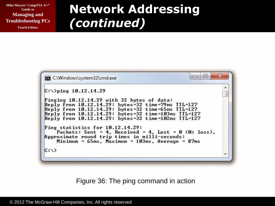
– Another example is a handy utility called ping. The ping command enables one machine to check
whether it can communicate with another machine.
© 2012 The McGraw-Hill Companies, Inc. All rights reserved
Mike Meyers’ CompTIA A+®
Guide to
Managing and
Troubleshooting PCs
Fourth Edition
Network Addressing (continued)
Figure 1: Typical fiber optic cables with connectors
Figure 36: The ping command in action

© 2012 The McGraw-Hill Companies, Inc. All rights reserved
Mike Meyers’ CompTIA A+®
Guide to
Managing and
Troubleshooting PCs
Fourth Edition
Network Addressing (continued)
• TCP/IP Services (continued)
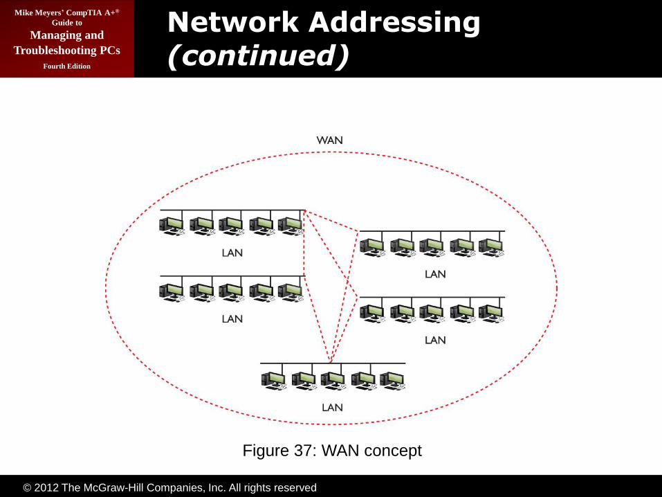
– The goal of TCP/IP is to link any two hosts (a computer or device), whether they are on the same
LAN or on some other network within the WAN.
– To move traffic between networks, you use routers. Each host sends traffic to the router only when that data is destined for a remote network, cutting
down on traffic across the more expensive WAN links. The host makes these decisions based on the destination IP address of each packet.
© 2012 The McGraw-Hill Companies, Inc. All rights reserved
Mike Meyers’ CompTIA A+®
Guide to
Managing and
Troubleshooting PCs
Fourth Edition
Network Addressing (continued)
Figure 1: Typical fiber optic cables with connectors Figure 37: WAN concept

© 2012 The McGraw-Hill Companies, Inc. All rights reserved
Mike Meyers’ CompTIA A+®
Guide to
Managing and
Troubleshooting PCs
Fourth Edition
Network Addressing (continued)
Figure 1: Typical fiber optic cables with connectors
Figure 38: Typical router

© 2012 The McGraw-Hill Companies, Inc. All rights reserved
Mike Meyers’ CompTIA A+®
Guide to
Managing and
Troubleshooting PCs
Fourth Edition
Network Addressing (continued)
• TCP/IP Settings
– TCP/IP has a number of unique settings that you must configure correctly to ensure proper network
functionality.
– In Windows, you can configure network settings from the appropriate networking applet.
– To open Network Connections in Windows XP,
either right-click on My Network Places and select Properties or open the Control Panel and select Network Connections.

© 2012 The McGraw-Hill Companies, Inc. All rights reserved
Mike Meyers’ CompTIA A+®
Guide to
Managing and
Troubleshooting PCs
Fourth Edition
Network Addressing (continued)
• TCP/IP Settings (continued)
– In Windows Vista and Windows 7, either right-click on Network and select Properties or open the
Control Panel and select Network and Sharing Center. In Windows Vista, you’ll also need to click the Manage network connections link; in Windows 7, you’ll need to click Change adapter settings.
– Every machine must be assigned an IP address, a subnet mask, a default gateway, and at least one DNS server.

© 2012 The McGraw-Hill Companies, Inc. All rights reserved
Mike Meyers’ CompTIA A+®
Guide to
Managing and
Troubleshooting PCs
Fourth Edition
Network Addressing (continued)
Figure 1: Typical fiber optic cables with connectors
Figure 39: Network Connections showing dial-up and LAN connections

© 2012 The McGraw-Hill Companies, Inc. All rights reserved
Mike Meyers’ CompTIA A+®
Guide to
Managing and
Troubleshooting PCs
Fourth Edition
Network Addressing (continued)
• TCP/IP Settings (continued)
– These settings can be added manually by using the TCP/IP Properties dialog box. When you set the IP
address manually, the IP address will not change and is called a static IP address.
– The Dynamic Host Configuration Protocol (DHCP) enables you to create a pool of IP addresses that
are given temporarily to machines.
– DHCP is especially handy for networks of laptops that individually join and leave the network on a regular basis.

© 2012 The McGraw-Hill Companies, Inc. All rights reserved
Mike Meyers’ CompTIA A+®
Guide to
Managing and
Troubleshooting PCs
Fourth Edition
Network Addressing (continued)
Figure 1: Typical fiber optic cables with connectors
Figure 40: Setting a static IP address

© 2012 The McGraw-Hill Companies, Inc. All rights reserved
Mike Meyers’ CompTIA A+®
Guide to
Managing and
Troubleshooting PCs
Fourth Edition
Network Addressing (continued)
Figure 1: Typical fiber optic cables with connectors
Figure 41: Automatically obtaining an IP address

© 2012 The McGraw-Hill Companies, Inc. All rights reserved
Mike Meyers’ CompTIA A+®
Guide to
Managing and
Troubleshooting PCs
Fourth Edition
Network Addressing (continued)
• TCP/IP Settings (continued)
– If you add a NIC to a Windows system, the default TCP/IP settings are set to use DHCP. When you
accept those automatic settings, you’re really telling the machine to use DHCP.
– To use DHCP you need a DHCP server. A DHCP server can be a program running on any computer
in your network, but most commonly it’s a feature added to routers.

© 2012 The McGraw-Hill Companies, Inc. All rights reserved
Mike Meyers’ CompTIA A+®
Guide to
Managing and
Troubleshooting PCs
Fourth Edition
Network Addressing (continued)
• TCP/IP Tools—all versions of Windows come with handy tools to test and configure TCP/IP.
– All of these programs are command-line utilities—
you must open a command prompt to run them.
– Ping is a great way to see if another system is connected to the network. Here’s how it works. Get to a command prompt and type ping followed by an IP address or by a DNS name, such as ping
www.totalsem.com, and press the ENTER key.

© 2012 The McGraw-Hill Companies, Inc. All rights reserved
Mike Meyers’ CompTIA A+®
Guide to
Managing and
Troubleshooting PCs
Fourth Edition
Network Addressing (continued)
Figure 1: Typical fiber optic cables with connectors
Figure 42: The ping command’s syntax

© 2012 The McGraw-Hill Companies, Inc. All rights reserved
Mike Meyers’ CompTIA A+®
Guide to
Managing and
Troubleshooting PCs
Fourth Edition
Network Addressing (continued)
• TCP/IP Tools (continued)
– The ping command has a few useful options beyond the basics. The first option is the –t switch.
If you use the –t switch, ping continuously sends ping packets until you stop it with the break command (CTRL-C). The second option is the –l switch, which enables you to specify how big a ping
packet to send. This helps in diagnosing specific problems with the routers between your computer and the computer you ping.
– Use the command-line tool ipconfig for a quick glance at your network settings. From a command
prompt, type ipconfig /all to see all of your TCP/IP settings.

© 2012 The McGraw-Hill Companies, Inc. All rights reserved
Mike Meyers’ CompTIA A+®
Guide to
Managing and
Troubleshooting PCs
Fourth Edition
Network Addressing (continued)
• TCP/IP Tools (continued)
– When you have a static IP address, ipconfig does little beyond reporting your current IP settings,
including your IP address, subnet mask, default gateway, DNS servers, and WINS servers. When using DHCP, however, ipconfig is also the primary tool for releasing and renewing your IP address.
Just type ipconfig /renew to get a new IP address or ipconfig /release to give up the IP address you currently have.

© 2012 The McGraw-Hill Companies, Inc. All rights reserved
Mike Meyers’ CompTIA A+®
Guide to
Managing and
Troubleshooting PCs
Fourth Edition
Network Addressing (continued)
Figure 1: Typical fiber optic cables with connectors
Figure 43: An ipconfig /all command on Windows 7

© 2012 The McGraw-Hill Companies, Inc. All rights reserved
Mike Meyers’ CompTIA A+®
Guide to
Managing and
Troubleshooting PCs
Fourth Edition
Network Addressing (continued)
• TCP/IP Tools (continued)
– The nslookup command is a powerful command-line program that enables you to determine exactly
what information the DNS server is giving you about a specific host name.
– Type nslookup from the command prompt and press the ENTER key.

© 2012 The McGraw-Hill Companies, Inc. All rights reserved
Mike Meyers’ CompTIA A+®
Guide to
Managing and
Troubleshooting PCs
Fourth Edition
Network Addressing (continued)
Figure 1: Typical fiber optic cables with connectors
Figure 44: The nslookup command in action
© 2012 The McGraw-Hill Companies, Inc. All rights reserved
Mike Meyers’ CompTIA A+®
Guide to
Managing and
Troubleshooting PCs
Fourth Edition
Network Addressing (continued)
• TCP/IP Tools (continued)
– The tracert utility shows the route that a packet takes to get to its destination. From a command
line, type tracert followed by a space and an IP address or URL.
– The output describes the route from your machine to the destination machine, including all devices
the packet passes through and how long each hop between devices takes.

© 2012 The McGraw-Hill Companies, Inc. All rights reserved
Mike Meyers’ CompTIA A+®
Guide to
Managing and
Troubleshooting PCs
Fourth Edition
Network Addressing (continued)
Figure 1: Typical fiber optic cables with connectors
Figure 45: The tracert command in action

© 2012 The McGraw-Hill Companies, Inc. All rights reserved
Mike Meyers’ CompTIA A+®
Guide to
Managing and
Troubleshooting PCs
Fourth Edition
Network Addressing (continued)
• TCP/IP Tools (continued)
– The tracert command can come in handy when you have to troubleshoot bottlenecks. When users
complain of difficulty reaching a particular destination by using TCP/IP, you can run this utility to determine whether the problem exists on a machine or connection over which you have
control, or if it is a problem on another machine or router.
– If a destination is completely unreachable, tracert can again determine whether the problem is on a machine or router over which you have control.

© 2012 The McGraw-Hill Companies, Inc. All rights reserved
Mike Meyers’ CompTIA A+®
Guide to
Managing and
Troubleshooting PCs
Fourth Edition
Network Addressing (continued)
• Configuring TCP/IP
– By default, TCP/IP is configured to receive an IP address automatically from a DHCP server on the
network (and automatically assign a corresponding subnet mask).
– CompTIA expects you to know how to do it manually.

© 2012 The McGraw-Hill Companies, Inc. All rights reserved
Mike Meyers’ CompTIA A+®
Guide to
Managing and
Troubleshooting PCs
Fourth Edition
Network Addressing (continued)
Figure 1: Typical fiber optic cables with connectors
Figure 46: Setting up IP

© 2012 The McGraw-Hill Companies, Inc. All rights reserved
Mike Meyers’ CompTIA A+®
Guide to
Managing and
Troubleshooting PCs
Fourth Edition
Network Addressing (continued)
• Automatic Private IP Addressing
– Windows supports a feature called Automatic Private IP Addressing (APIPA) that automatically
assigns an IP address to the system when the client cannot obtain an IP address automatically.
– The Internet Assigned Numbers Authority, the nonprofit corporation responsible for assigning IP
addresses and managing root servers, has set aside the range of addresses from 169.254.0.1 to 169.254.255.254 for this purpose.

© 2012 The McGraw-Hill Companies, Inc. All rights reserved
Mike Meyers’ CompTIA A+®
Guide to
Managing and
Troubleshooting PCs
Fourth Edition
Network Addressing (continued)
• Automatic Private IP Addressing (continued)
– If the computer system cannot contact a DHCP server, the computer randomly chooses an address in the form of 169.254.x.y (where x.y is the computer’s identifier) and a 16-bit subnet mask
(255.255.0.0) and broadcasts it on the network segment (subnet).

© 2012 The McGraw-Hill Companies, Inc. All rights reserved
Mike Meyers’ CompTIA A+®
Guide to
Managing and
Troubleshooting PCs
Fourth Edition
Network Addressing (continued)
• Automatic Private IP Addressing (continued)
– If no other computer responds to the address, the system assigns this address to itself. When using APIPA, the system can communicate only with other computers on the same subnet that also use
the 169.254.x.y range with a 16-bit mask. APIPA is enabled by default if your system is configured to obtain an IP address automatically.
© 2012 The McGraw-Hill Companies, Inc. All rights reserved
Mike Meyers’ CompTIA A+®
Guide to
Managing and
Troubleshooting PCs
Fourth Edition
IPv6
• TCP/IP development took place back in the early 1970s. There were fewer than 1000 computers in the entire world at the time.
– In 1979, developers created the Internet Protocol version 4 (IPv4) 32-bit IP address space, creating approximately four billion IP addresses.
– Then the TCP/IP folks wasted huge chunks of IP addresses due to classful addressing and a wasteful method of parceling out IP addresses.
– The Internet also reached a level of popularity far beyond the original developers’ imaginations.

© 2012 The McGraw-Hill Companies, Inc. All rights reserved
Mike Meyers’ CompTIA A+®
Guide to
Managing and
Troubleshooting PCs
Fourth Edition
IPv6 (continued)
• TCP/IP development (continued)
– As a result, the Internet Engineering Task Force (IETF) developed a new IP addressing scheme
called Internet Protocol version 6 (IPv6) that is slowly replacing IPv4.
• IPv6 extends the 32-bit IP address space to 128 bits, allowing up to 2128
addresses.

© 2012 The McGraw-Hill Companies, Inc. All rights reserved
Mike Meyers’ CompTIA A+®
Guide to
Managing and
Troubleshooting PCs
Fourth Edition
IPv6 (continued)
• IPv6 Address Notation: The familiar 32-bit IPv4 addresses are written as 197.169.94.82, using four octets. The 128-bit IPv6 addresses are written like this: 2001:0000:0000:3210:0800:200C:00CF:1234
– IPv6 uses a colon as a separator, instead of the period used in IPv4’s dotted-decimal format. Each ―group‖ is a hexadecimal number between 0000 and FFFF called (unofficially) a field or hextet.
– A complete IPv6 address always has eight groups
of four hexadecimal characters.

© 2012 The McGraw-Hill Companies, Inc. All rights reserved
Mike Meyers’ CompTIA A+®
Guide to
Managing and
Troubleshooting PCs
Fourth Edition
IPv6 (continued)
• IPv6 Address Notation (continued)
– Several ways to shorten: First, leading zeros can be dropped from any group, so 00CF becomes CF
and 0000 becomes 0.
– Second, you can remove one or more consecutive groups of all zeros, leaving two colons together.
– You can remove any number of consecutive groups
of zeros to leave a double colon, but you can only do this once in an IPv6 address.
– IPv6 still uses subnets. IPv6 uses the ―/x‖Classless Inter-Domain Routing (CIDR) nomenclature, where the /x refers to the number
of bits in the subnet mask, just like in IPv4.

© 2012 The McGraw-Hill Companies, Inc. All rights reserved
Mike Meyers’ CompTIA A+®
Guide to
Managing and
Troubleshooting PCs
Fourth Edition
IPv6 (continued)
• Instead of one IP address, you can have up to three IP addresses on a single network card.
– When a computer running IPv6 first boots up, it
gives itself a link-local address, IPv6’s equivalent to IPv4’s APIPA address. The first 64 bits of a link-local address are always FE80::. That means every address always begins with FE80:0000:0000:0000

© 2012 The McGraw-Hill Companies, Inc. All rights reserved
Mike Meyers’ CompTIA A+®
Guide to
Managing and
Troubleshooting PCs
Fourth Edition
IPv6 (continued)
Figure 1: Typical fiber optic cables with connectors
Figure 47: Link-local address in ipconfig

© 2012 The McGraw-Hill Companies, Inc. All rights reserved
Mike Meyers’ CompTIA A+®
Guide to
Managing and
Troubleshooting PCs
Fourth Edition
IPv6 (continued)
• IPv6 IP addresses (continued)
– The operating system has a choice on how to make the last 64 bits of an IPv6 address. The first
method uses a random value—and this is the way Windows does it by default. When you activate a NIC, Windows simply makes a random value for the last 64 bits of the IPv6 address. Once created,
this unique 64-bit value will never change.
– Non-Windows operating systems use the second method, which creates the IPv6 address using the MAC address of the network card (called the Extended Unique Identifier, 64-bit, or EUI-64).
© 2012 The McGraw-Hill Companies, Inc. All rights reserved
Mike Meyers’ CompTIA A+®
Guide to
Managing and
Troubleshooting PCs
Fourth Edition
IPv6 (continued)
• IPv6 Subnet Masks
– IPv6 subnets function the same as IPv4 subnets, but there are two new rules:
– The last 64 bits of an IPv6 address are generated randomly or using the MAC address, leaving a maximum of 64 bits for the network ID. Therefore, no subnet is ever longer than /64.
– The IANA passes out /32 subnets to big ISPs and end users who need large allotments. ISPs and others may pass out /48 and /64 subnets to end users.
– The vast majority of IPv6 subnets are between /48
and /64.

© 2012 The McGraw-Hill Companies, Inc. All rights reserved
Mike Meyers’ CompTIA A+®
Guide to
Managing and
Troubleshooting PCs
Fourth Edition
IPv6 (continued)
• Global Addresses—to get on the Internet, a system needs a second IPv6 address called a global address.
– The most common way to get a global address is to
request it from the default gateway router, which must be configured to pass out global IPv6 addresses.
– When you plug a computer into a network, it sends out a very special packet called a router solicitation
(RS) message, looking for a router. The router hears this message and responds with a router advertisement (RA). This RA tells the computer its network ID and subnet (together called the prefix)
and DNS server (if configured).

© 2012 The McGraw-Hill Companies, Inc. All rights reserved
Mike Meyers’ CompTIA A+®
Guide to
Managing and
Troubleshooting PCs
Fourth Edition
IPv6 (continued)
Figure 1: Typical fiber optic cables with connectorsFigure 48: Getting a global address

© 2012 The McGraw-Hill Companies, Inc. All rights reserved
Mike Meyers’ CompTIA A+®
Guide to
Managing and
Troubleshooting PCs
Fourth Edition
IPv6 (continued)
• Global Addresses (continued)
– Once the computer gets a prefix, it generates the rest of the address just as it does the link-local
address. The computer ends up with a legitimate, 128-bit public IPv6 address as well as a link-local address.
• The addition of IPv6 makes programs such as ipconfig fairly complex. With multiple NICs and both IPv4 and IPv6, the output is vast—too big to even put on a single screen.

© 2012 The McGraw-Hill Companies, Inc. All rights reserved
Mike Meyers’ CompTIA A+®
Guide to
Managing and
Troubleshooting PCs
Fourth Edition
IPv6 (continued)
Figure 1: Typical fiber optic cables with connectors
Figure 49: Windows system with a global IPv6 address

© 2012 The McGraw-Hill Companies, Inc. All rights reserved
Mike Meyers’ CompTIA A+®
Guide to
Managing and
Troubleshooting PCs
Fourth Edition
IPv6 (continued)
Figure 1: Typical fiber optic cables with connectors
Figure 50: The ipconfig command with IPv6 and IPv4

© 2012 The McGraw-Hill Companies, Inc. All rights reserved
Mike Meyers’ CompTIA A+®
Guide to
Managing and
Troubleshooting PCs
Fourth Edition
Installing and Configuring a Wired Network
© 2012 The McGraw-Hill Companies, Inc. All rights reserved
Mike Meyers’ CompTIA A+®
Guide to
Managing and
Troubleshooting PCs
Fourth Edition
Installing a NIC
• To have network connectivity, you need to have three things in place:
– NIC—the physical hardware that connects the computer system to the network media
– Protocol—the language that the computer systems use to communicate
– Network client—the interface that allows the computer system to speak to the protocol
• The NIC is your computer system’s link to the network.

© 2012 The McGraw-Hill Companies, Inc. All rights reserved
Mike Meyers’ CompTIA A+®
Guide to
Managing and
Troubleshooting PCs
Fourth Edition
Installing a NIC (continued)
• NICs are manufactured to operate on specific media and network types, such as 1000BaseT Ethernet. Follow the manufacturer’s instructions for installation.

© 2012 The McGraw-Hill Companies, Inc. All rights reserved
Mike Meyers’ CompTIA A+®
Guide to
Managing and
Troubleshooting PCs
Fourth Edition
Installing a NIC (continued)
• If it’s a new NIC, it will be detected, installed, and configured automatically by
Windows. You may need updated drivers from the manufacturer’s Web site
– The Add Hardware Wizard in Windows XP automates installation of non–plug-and-play devices or plug-and-play devices that were not detected correctly.
– If, for some reason, Windows Vista or Windows 7 doesn’t automatically detect a new NIC after you turn the PC back on, go to Start | Control Panel | Add Hardware in Windows Vista or Start | Devices and Printers and click on Add a Device in Windows 7 to install it.
© 2012 The McGraw-Hill Companies, Inc. All rights reserved
Mike Meyers’ CompTIA A+®
Guide to
Managing and
Troubleshooting PCs
Fourth Edition
Installing a NIC (continued)
• Duplex and Half-Duplex
– All modern NICs can run in full-duplex mode, meaning they can send and receive data at the
same time.
– The vast majority of NICs and switches use a feature called auto-sensing to accommodate very old devices that might attach to the network and
need to run in half-duplex mode.
– Half-duplex means that the device can send and receive, but not at the same time. An obvious example of a half-duplex device is a walkie-talkie.
– Half-duplex devices are exceedingly rare in modern
computers, but you need to understand this option.

© 2012 The McGraw-Hill Companies, Inc. All rights reserved
Mike Meyers’ CompTIA A+®
Guide to
Managing and
Troubleshooting PCs
Fourth Edition
Installing a NIC (continued)
• Link lights
– NICs made today have some type of light-emitting diode (LED) status indicator that gives information
about the state of the NIC’s link to whatever is on the other end of the connection.
– The lights are actually LEDs, but techs use the term link lights.
– NICs can have between one and four different link lights, and the LEDs can be any color.
– Link lights are one of the first items to check whenever you think a system is disconnected from the network.

© 2012 The McGraw-Hill Companies, Inc. All rights reserved
Mike Meyers’ CompTIA A+®
Guide to
Managing and
Troubleshooting PCs
Fourth Edition
Installing a NIC (continued)
Figure 1: Typical fiber optic cables with connectors
Figure 51: Mmmm, pretty lights!

© 2012 The McGraw-Hill Companies, Inc. All rights reserved
Mike Meyers’ CompTIA A+®
Guide to
Managing and
Troubleshooting PCs
Fourth Edition
Installing a NIC (continued)
• Link lights (continued)
– Switches also have link lights, enabling you to check the connectivity at both ends of the cable. If a PC can’t access a network, always check the link lights first. Multispeed devices usually have a link light that tells you the speed of the connection (usually orange and green).
– A properly functioning link light is steady on when the NIC is connected to another device—no flickering, no on and off, just on. A link light that is off or flickering shows a connection problem.
– Another light is the activity light. This light turns on when the card detects network traffic, so it makes an intermittent flickering when operating properly.

© 2012 The McGraw-Hill Companies, Inc. All rights reserved
Mike Meyers’ CompTIA A+®
Guide to
Managing and
Troubleshooting PCs
Fourth Edition
Installing a NIC (continued)
Figure 1: Typical fiber optic cables with connectors
Figure 52: Multispeed lights

© 2012 The McGraw-Hill Companies, Inc. All rights reserved
Mike Meyers’ CompTIA A+®
Guide to
Managing and
Troubleshooting PCs
Fourth Edition
Installing a NIC (continued)
• Link lights (continued)
– No standard governs how NIC manufacturers use their lights; as a result, LEDs in NICs come in a
wide array of colors and layouts, so take the time to determine what the lights on the particular network card mean.
© 2012 The McGraw-Hill Companies, Inc. All rights reserved
Mike Meyers’ CompTIA A+®
Guide to
Managing and
Troubleshooting PCs
Fourth Edition
Installing a NIC (continued)
• Wake on LAN
– A popular feature of most NICs is the ability to turn on or wake up a powered-down or sleeping PC.
– Wake on LAN is handy when you want to wake up one or multiple computers that you aren’t physically near.
– To wake up a PC with Wake on LAN, you’ll need to
use a second PC to send either a special pattern or a magic packet (a broadcast packet that essentially repeats the destination MAC address many times).

© 2012 The McGraw-Hill Companies, Inc. All rights reserved
Mike Meyers’ CompTIA A+®
Guide to
Managing and
Troubleshooting PCs
Fourth Edition
Installing a NIC (continued)
• Wake on LAN (continued)
– A powered-down or sleeping PC knows to look for this special pattern or packet, at least after being
configured to do so.
– In Windows XP, go to the Control Panel and open Network Connections. In Windows Vista/7, go to the Control Panel and open Network and Sharing
Center. Click Manage network connections (Vista) or Change adapter settings (7) on the left.
– For all versions of Windows, right-click on the adapter and select Properties. Click the Configure button in the Properties dialog box and then select
the Power Management tab.
© 2012 The McGraw-Hill Companies, Inc. All rights reserved
Mike Meyers’ CompTIA A+®
Guide to
Managing and
Troubleshooting PCs
Fourth Edition
Installing a NIC (continued)
• Wake on LAN (continued)
– To enable Wake on LAN, make sure the checkbox next to Allow this device to wake the computer is
checked. Optionally, you can select Only allow a magic packet to wake the computer, which will instruct the NIC to ignore everything but magic packets.
– Wake on LAN can wake up or turn on laptops using wireless connections, even when they aren’t plugged in or are inside a carrying case. Don’t let your laptop’s battery die or overheat—unless you know that you’ll need it, turn off Wake on LAN on
your laptop.

© 2012 The McGraw-Hill Companies, Inc. All rights reserved
Mike Meyers’ CompTIA A+®
Guide to
Managing and
Troubleshooting PCs
Fourth Edition
Installing a NIC (continued)
Figure 1: Typical fiber optic cables with connectors
Figure 53: Wake on LAN settings on the Power Management tab

© 2012 The McGraw-Hill Companies, Inc. All rights reserved
Mike Meyers’ CompTIA A+®
Guide to
Managing and
Troubleshooting PCs
Fourth Edition
Configuring a Network Client
• To establish network connectivity, you need a network client installed and configured properly.
• Installed as part of the OS installation, the Client for Microsoft Networks rarely needs configuration, and, in fact, few configuration options are available.

© 2012 The McGraw-Hill Companies, Inc. All rights reserved
Mike Meyers’ CompTIA A+®
Guide to
Managing and
Troubleshooting PCs
Fourth Edition
Configuring a Network Client (continued)
• To start it in Windows Vista/7, click Start, right-click Network, and select Properties.
Then click Manage network connections (Vista) or Change adapter settings (7) on the left. In Windows XP, click Start, right-click My Network Places, and select Properties.
– In all versions of Windows, the next step is to double-click the Local Area Connection icon, click the Properties button, and highlight Client for Microsoft Networks.
– In Windows XP/Vista, click the Properties button.
Windows 7 disables this option.

© 2012 The McGraw-Hill Companies, Inc. All rights reserved
Mike Meyers’ CompTIA A+®
Guide to
Managing and
Troubleshooting PCs
Fourth Edition
Sharing and Security
• Windows systems can share all kinds of resources, including files, folders, drives, printers, faxes, and Internet connections.

© 2012 The McGraw-Hill Companies, Inc. All rights reserved
Mike Meyers’ CompTIA A+®
Guide to
Managing and
Troubleshooting PCs
Fourth Edition
Sharing and Security (continued)
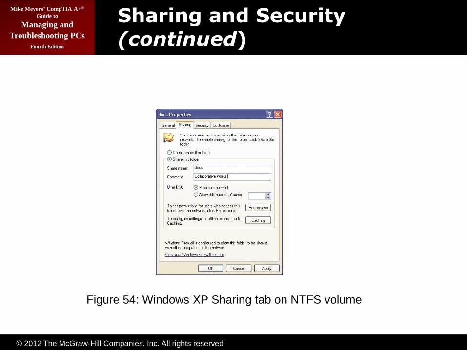
• To share a drive or folder, right-click the drive or folder, click Properties, and then click the Sharing tab.
– When you share a drive, you need to set a share
name, without spaces. In Windows Vista/7, click the Advanced Sharing button. Select Share this folder, add something in the Comment or User limit fields if you wish (they’re not required).
© 2012 The McGraw-Hill Companies, Inc. All rights reserved
Mike Meyers’ CompTIA A+®
Guide to
Managing and
Troubleshooting PCs
Fourth Edition
Sharing and Security (continued)
Figure 1: Typical fiber optic cables with connectors
Figure 54: Windows XP Sharing tab on NTFS volume

© 2012 The McGraw-Hill Companies, Inc. All rights reserved
Mike Meyers’ CompTIA A+®
Guide to
Managing and
Troubleshooting PCs
Fourth Edition
Sharing and Security (continued)
Figure 1: Typical fiber optic cables with connectors
Figure 55: Network permissions

© 2012 The McGraw-Hill Companies, Inc. All rights reserved
Mike Meyers’ CompTIA A+®
Guide to
Managing and
Troubleshooting PCs
Fourth Edition
Sharing and Security (continued)
• To share a drive or folder (continued)
– You then need to determine the permissions. Windows provides for two sets of permissions:
Share permissions and NTFS permissions. Share (network) permissions offer Full Control, Change, and Read settings. If you are on NTFS and want to control the permissions even further, you need to
configure the NTFS permissions in addition to the network permissions.
– Once you share the drive, a small hand appears on the icon.

© 2012 The McGraw-Hill Companies, Inc. All rights reserved
Mike Meyers’ CompTIA A+®
Guide to
Managing and
Troubleshooting PCs
Fourth Edition
Sharing and Security (continued)
• To access shared drives/directories, you have a few choices:
– You can browse to them through My Network Places or Network (though this involves a lot of clicking).
– You can map a network drive to your system.
This means the network drive shows up in My Computer/Computer as a drive. The icon will look different and will have a letter, but the letter is not part of the network drive.

© 2012 The McGraw-Hill Companies, Inc. All rights reserved
Mike Meyers’ CompTIA A+®
Guide to
Managing and
Troubleshooting PCs
Fourth Edition
Sharing and Security (continued)
Figure 1: Typical fiber optic cables with connectors
Figure 56: Shared resources in Network

© 2012 The McGraw-Hill Companies, Inc. All rights reserved
Mike Meyers’ CompTIA A+®
Guide to
Managing and
Troubleshooting PCs
Fourth Edition
Sharing and Security (continued)
Figure 57: Map Network Drive dialog box in Windows 7

© 2012 The McGraw-Hill Companies, Inc. All rights reserved
Mike Meyers’ CompTIA A+®
Guide to
Managing and
Troubleshooting PCs
Fourth Edition
Sharing and Security (continued)
Figure 1: Typical fiber optic cables with connectorsFigure 58: Browsing for shared folders

© 2012 The McGraw-Hill Companies, Inc. All rights reserved
Mike Meyers’ CompTIA A+®
Guide to
Managing and
Troubleshooting PCs
Fourth Edition
Sharing and Security (continued)
Figure 1: Typical fiber optic cables with connectors
Figure 59: Adding a network location to the Windows 7 Navigation pane
© 2012 The McGraw-Hill Companies, Inc. All rights reserved
Mike Meyers’ CompTIA A+®
Guide to
Managing and
Troubleshooting PCs
Fourth Edition
Sharing and Security (continued)
• To access shared drives/directories (continued)
– The universal naming convention (UNC) can also be used to access shared files. All computers have a name, and all shared resources have a name. The UNC name uses the computer name and the share
name as \\ServerName\ShareName\FileName. All files and folders have a pathname. For example,
C:\FREDC\INSTALL-FILES\SETUP.EXE

© 2012 The McGraw-Hill Companies, Inc. All rights reserved
Mike Meyers’ CompTIA A+®
Guide to
Managing and
Troubleshooting PCs
Fourth Edition
Sharing and Security (continued)
• To access shared drives/directories (continued)
– All network drives and their shared resources also have a pathname beginning with double backslashes, the server name, a single backslash, the share name, and the rest of the path. For
example,
\\SERVER\FREDC\INSTALL-FILES\SETUP.EXE

© 2012 The McGraw-Hill Companies, Inc. All rights reserved
Mike Meyers’ CompTIA A+®
Guide to
Managing and
Troubleshooting PCs
Fourth Edition
Sharing and Security (continued)
• NET command
– NET VIEW—this command displays a list of the NetBIOS names of computers available on the
network. The NET VIEW command followed by a NetBIOS name will display a list of available shared folders.
– NET USE—CLI command for mapping network
drives. For example, to map drive letter X: to the Research folder on a server named SERVER1, you would use the NET USE X: \\SERVER1\Research command.

© 2012 The McGraw-Hill Companies, Inc. All rights reserved
Mike Meyers’ CompTIA A+®
Guide to
Managing and
Troubleshooting PCs
Fourth Edition
Sharing and Security (continued)
• NBTSTAT command
– The nbtstat command is an old command-line utility that goes back to before Windows. It stands
for NetBIOS over TCP/IP Statistics.
– It is a great tool for learning anything Windows-related you want to know about your network, such as ―What other workgroups or domains are on this
network‖?

© 2012 The McGraw-Hill Companies, Inc. All rights reserved
Mike Meyers’ CompTIA A+®
Guide to
Managing and
Troubleshooting PCs
Fourth Edition
Sharing and Security (continued)
• Sharing printers
– Sharing a printer is similar to sharing a drive. Right-click the printer, select Properties, and then
Sharing. Select Share as or Share the printer and give the printer a name.
– To access a shared printer, install a network printer on a workstation. Use the Add Printer Wizard and
select Network Printer when prompted. Browse to the network printer using the UNC. Usually, setup will just copy the printer drivers from the network computer. If not, it will prompt you for the driver disk.

© 2012 The McGraw-Hill Companies, Inc. All rights reserved
Mike Meyers’ CompTIA A+®
Guide to
Managing and
Troubleshooting PCs
Fourth Edition
Sharing and Security (continued)
Figure 1: Typical fiber optic cables with connectors
Figure 60: Giving a name to a shared printer on Windows XP

© 2012 The McGraw-Hill Companies, Inc. All rights reserved
Mike Meyers’ CompTIA A+®
Guide to
Managing and
Troubleshooting PCs
Fourth Edition
Troubleshooting Networks

© 2012 The McGraw-Hill Companies, Inc. All rights reserved
Mike Meyers’ CompTIA A+®
Guide to
Managing and
Troubleshooting PCs
Fourth Edition
Repairing Physical Cabling
• Symptoms—total loss of connectivity
– Pop-up warnings (XP) and icons (Vista/7) showing loss of connectivity
– First check the obvious—is the cable unplugged at your system? At the wall outlet?
– Then the less obvious—is the NIC disabled in Device Manager? Is the cable connected to the
switch?
• Diagnosing physical problems—intermittent loss is harder to trace
– Look for errors that point to physical disconnection
– A ―No server is found‖ error or other errors

© 2012 The McGraw-Hill Companies, Inc. All rights reserved
Mike Meyers’ CompTIA A+®
Guide to
Managing and
Troubleshooting PCs
Fourth Edition
Repairing Physical Cabling (continued)
Figure 1: Typical fiber optic cables with connectors
Figure 61: Windows XP pop-up message and red X error icon

© 2012 The McGraw-Hill Companies, Inc. All rights reserved
Mike Meyers’ CompTIA A+®
Guide to
Managing and
Troubleshooting PCs
Fourth Edition
Repairing Physical Cabling (continued)
Figure 1: Typical fiber optic cables with connectors
Figure 62: Windows 7 red X error icon

© 2012 The McGraw-Hill Companies, Inc. All rights reserved
Mike Meyers’ CompTIA A+®
Guide to
Managing and
Troubleshooting PCs
Fourth Edition
Repairing Physical Cabling (continued)
• Check the Lights
– If you suspect a hardware problem, first check the link lights on the NIC and switch. If they’re not lit,
you know the cable isn’t connected somewhere.
– Eliminate the possibility of a failed switch or other larger problem by checking to make sure other people can access the network, and that other
systems can access the shared resource (server) that the problem system can’t see
– Inspect the cable running from the back of the PC to the outlet. Finally, if you can, plug the system into a known good outlet and see if it works.
© 2012 The McGraw-Hill Companies, Inc. All rights reserved
Mike Meyers’ CompTIA A+®
Guide to
Managing and
Troubleshooting PCs
Fourth Edition
Repairing Physical Cabling (continued)
• Check the Lights (continued)
– If you get connectivity with the second outlet, you should begin to suspect the structured cable
running from the first outlet to the switch.

© 2012 The McGraw-Hill Companies, Inc. All rights reserved
Mike Meyers’ CompTIA A+®
Guide to
Managing and
Troubleshooting PCs
Fourth Edition
Repairing Physical Cabling (continued)
• Check the NIC
– A bad NIC can also generate a ―can’t see the network‖ problem.
– Use the utility provided by the OS to verify that the NIC works. If you’ve got a NIC with diagnostic software, run it—this software will check the NIC’s circuitry.
– The NIC’s female connector is a common failure point, so NICs that come with diagnostic software often include a special test called a loopback test.

© 2012 The McGraw-Hill Companies, Inc. All rights reserved
Mike Meyers’ CompTIA A+®
Guide to
Managing and
Troubleshooting PCs
Fourth Edition
Repairing Physical Cabling (continued)
• Check the NIC (continued)
– A loopback test sends data out of the NIC and checks to see if it comes back. Some NICs perform
only an internal loopback, which tests the circuitry that sends and receives, but not the actual connecting pins.
– A true external loopback requires a loopback plug
inserted into the NIC’s port.
– If the NIC is bad, replace it.

© 2012 The McGraw-Hill Companies, Inc. All rights reserved
Mike Meyers’ CompTIA A+®
Guide to
Managing and
Troubleshooting PCs
Fourth Edition
Repairing Physical Cabling (continued)
Figure 1: Typical fiber optic cables with connectors
Figure 63: Loopback plug

© 2012 The McGraw-Hill Companies, Inc. All rights reserved
Mike Meyers’ CompTIA A+®
Guide to
Managing and
Troubleshooting PCs
Fourth Edition
Repairing Physical Cabling (continued)
• Cable Testing
– With the right equipment, diagnosing a bad horizontal cabling run is easy.
– A tech should own a midrange time-domain reflectometer (TDR) tester such as the Fluke MicroScanner.
– A TDR measures impedance in network cabling.
If the tester measures any impedance, something is wrong with the cable.

© 2012 The McGraw-Hill Companies, Inc. All rights reserved
Mike Meyers’ CompTIA A+®
Guide to
Managing and
Troubleshooting PCs
Fourth Edition
Repairing Physical Cabling (continued)
• Cable Testing (continued)
– When you’re testing a cable run, always include the patch cables as you test. This means unplugging
the patch cable from the PC, attaching a tester, and then going to the telecommunications room. Here you’ll want to unplug the patch cable from the switch and plug the tester into that patch cable,
making a complete test.
– A bad patch cable is an easy fix, but a bad horizontal cable needs a total replacement.

© 2012 The McGraw-Hill Companies, Inc. All rights reserved
Mike Meyers’ CompTIA A+®
Guide to
Managing and
Troubleshooting PCs
Fourth Edition
Repairing Physical Cabling (continued)
Figure 1: Typical fiber optic cables with connectors
Figure 64: Loopback plug in action

© 2012 The McGraw-Hill Companies, Inc. All rights reserved
Mike Meyers’ CompTIA A+®
Guide to
Managing and
Troubleshooting PCs
Fourth Edition
Repairing Physical Cabling (continued)
• Toners
– You might eventually find yourself having to locate or trace cables, as labels fall off, new cable runs
are added, and mistakes are made.
– Network techs use a device called a toner for help in tracing cables.
– Toner is the generic term for two separate devices
that are used together: a tone generator and a tone probe.
– The tone generator connects to the cable using alligator clips, tiny hooks, or a network jack, and it sends an electrical signal along the wire at a
certain frequency.

© 2012 The McGraw-Hill Companies, Inc. All rights reserved
Mike Meyers’ CompTIA A+®
Guide to
Managing and
Troubleshooting PCs
Fourth Edition
Repairing Physical Cabling (continued)
• Toners (continued)
– The tone probe emits a sound when it is placed near a cable connected to the tone generator.
– These two devices are often referred to by the brand-name Fox and Hound, a popular model of toner made by the Triplett Corporation.

© 2012 The McGraw-Hill Companies, Inc. All rights reserved
Mike Meyers’ CompTIA A+®
Guide to
Managing and
Troubleshooting PCs
Fourth Edition
Repairing Physical Cabling (continued)
Figure 1: Typical fiber optic cables with connectors
Figure 65: Fox and Hound

© 2012 The McGraw-Hill Companies, Inc. All rights reserved
Mike Meyers’ CompTIA A+®
Guide to
Managing and
Troubleshooting PCs
Fourth Edition
Fixing Common Problems
• Failing to Connect to a New Resource
– Usually points to a configuration issue
– You don’t have the right share name? Go check at
the serving system.
– You don’t have the required user name/password? Ask someone who might have this knowledge, or double-check that your account has access.
– You don’t have permission to use/access/connect to the shared resource? Make sure you have the correct permissions.

© 2012 The McGraw-Hill Companies, Inc. All rights reserved
Mike Meyers’ CompTIA A+®
Guide to
Managing and
Troubleshooting PCs
Fourth Edition
Fixing Common Problems (continued)
• Failing to Connect to a New Resource (continued)
– You’re not on the right homegroup/domain/workgroup? Check your system and the sharing system to verify which workgroup/domain name to use. On a homegroup,
make sure you’ve used the proper password.
– The folder or printer isn’t shared? Share it!
– The folder or printer doesn’t exist? Make sure the serving system still hosts the folder you want.
Install the network printer if you haven’t yet.

© 2012 The McGraw-Hill Companies, Inc. All rights reserved
Mike Meyers’ CompTIA A+®
Guide to
Managing and
Troubleshooting PCs
Fourth Edition
Fixing Common Problems (continued)
• Failing to Connect to a Previously Used Resource
– Verify that you are not already connected by using nbtstat –s
– Check that you can see the resource using My Network Places/Network or net view.
– Check that the serving system is turned on.
– Check that the computer is physically connected to the serving system.