Embed Size (px)
Citation preview
Fourier information optics for the ultrafast time domain
Andrew M. WeinerSchool of Electrical and Computer Engineering, Purdue University, West Lafayette, Indiana 47907-1285, USA
Received 23 May 2007; revised 6 September 2007; accepted 7 September 2007;posted 11 September 2007 (Doc. ID 83200); published 26 November 2007
Ultrafast photonic signal processing based on Fourier optics principles offers exciting possibilities to gobeyond the processing speeds of electronics technologies for applications in high-speed fiber communi-cations and ultrawideband wireless. I review our recent work on processing of ultrafast optical signals viaconversion between time, space, and optical frequency (Fourier) domains. Specific topics include opticalarbitrary waveform generation, application of optical pulse shaping technologies for wavelength-parallelcompensation of fiber transmission impairments and for experimental studies of optical code-divisionmultiple-access communications, and application of photonic methods for precompensation of dispersioneffects in wireless transmission of radio-frequency signals over ultrawideband antenna links. © 2008Optical Society of America
OCIS codes: 320.5540, 060.7140, 320.5520.
1. Introduction
Emmett Leith, in whose memory this journal featureissue is dedicated, was a pioneer of the fields of in-formation optics, holography, optical signal process-ing, and imaging [1–4]. Much of his work drewheavily on the natural ability of optics to performFourier transforms in the spatial domain, e.g., inholographic recording of an object’s Fourier spectrumor in correlation processing via spatial filtering at aFourier plane. His research was concerned both withapplications to information that was inherently opti-cal (e.g., optical imaging) and to information in themicrowave domain that could be processed optically(e.g., synthetic aperture radar). During the latterpart of his career, he was also active in research inwhich Fourier principles in the time and optical fre-quency domains were exploited for imaging in scat-tering media via holographic range gating [5].
This paper surveys the author’s research on Fou-rier processing of ultrafast (picosecond and femtosec-ond) time-domain optical signals. As sketched in Fig.1, this research exploits mappings and transformsbetween fields in the spatial, temporal, and opticalfrequency domains. In particular, this paper focuseson methods for ultrafast optical waveform synthesis
and signal processing based on spatial manipulationof the dispersed optical frequency spectra of femto-second pulses. Using these methods, femtosecondpulses can be engineered into complex optical signalsaccording to specification. A key point is that wave-form synthesis is achieved by parallel modulation inthe frequency domain, which is achieved by spatialmodulation of the spatially dispersed optical fre-quency spectrum. Thus, waveforms with effective se-rial modulation bandwidths as high as terahertz canbe generated and manipulated without requiring anyultrafast modulators.
As applications of such optical processing methods,we discuss compensation of fiber transmission im-pairments, including both chromatic dispersion andpolarization-mode dispersion, as well as novel opticalcommunication systems based on encoding and decod-ing of ultrafast pulses. These examples exploit time–frequency Fourier techniques to perform matchedfiltering processing of ultrafast pulsed signals, in closeanalogy with the spatial Fourier techniques used byLeith and his colleagues for correlation processingof spatial domain optical signals. We also discussexperiments in which we have applied time-domainFourier pulse processing technology for generationof arbitrarily-shaped radio-frequency (RF) electricalwaveforms and compensation of chromatic dispersionin wireless transmission of ultrawideband RF signalsover broadband antenna links. Again, this use of time-
0003-6935/08/0400A88-9$15.00/0© 2008 Optical Society of America
A88 APPLIED OPTICS � Vol. 47, No. 4 � 1 February 2008
domain optical processing for manipulation of RF elec-trical signals may be seen as broadly analogous to themuch earlier use of spatial-domain optical processingfor manipulation of microwave (radar) signals.
2. Optical Pulse Shaping
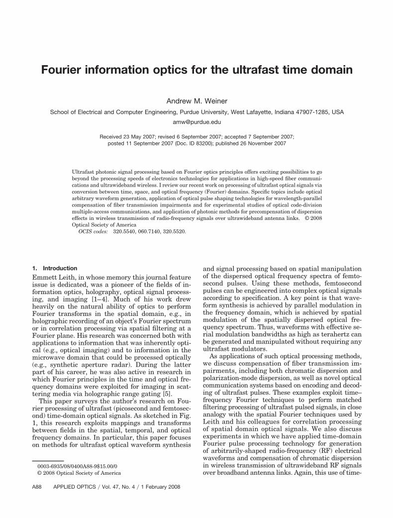
We first discuss femtosecond pulse shaping, in whichpowerful Fourier synthesis methods are utilized togenerate almost arbitrarily shaped femtosecond op-tical waveforms [6,7]. As sketched in Fig. 2(a), inpulse shaping an incident femtosecond pulse isspread into its constituent spectral components by agrating and lens. A spatially patterned mask thenmodulates the phase and amplitude of the spatiallydispersed spectral components. After the spectralcomponents are recombined by a second lens andgrating, a shaped output pulse is obtained, with thepulse shape given by the Fourier transform of thepattern transferred by the mask onto the spectrum.Examples of shaped pulses are shown in Figs. 2(b)and 2(c). Pulse shaping masks were originally imple-mented by using microlithographic patterning tech-niques and subsequently by using programmablespatial light modulators, acousto-optic modulators[8], holographic masks, and deformable mirrors. Inour laboratory, pulse shaping is normally performedusing programmable liquid crystal modulator arrays[9,10] that allow independent, simultaneous gray-level control of both spectral amplitude and phase.Pulse shaping is now used in laboratories around theworld for a broad range of applications, includingcoherent control over ultrafast physical processes,high field physics, nonlinear optical biomedical imag-ing, and high-speed communications. A review ofsome of these applications is given in Refs. [7,11].
In our work and in the examples described below,we generally emphasize manipulation of spectralphase, which, compared to other spectral parameters,arguably has the most fundamental impact ontemporal waveforms. We note, however, that spec-tral amplitude filtering, using optical arrangementsbased on that of Fig. 2, is commonly employed inwavelength-division multiplexed (WDM) optical com-munications for subsystems such as spectral gainequalizers and reconfigurable optical add–drop mul-tiplexers [12]. Furthermore, polarization pulse shap-
ing, in which the spectral or temporal polarizationprofile of a pulse is manipulated, has become a topicof significant current interest [13]. Polarization pulseshaping has applications both in fundamental areassuch as attosecond pulse generation and coherentcontrol and in technology, such as our work on com-pensation of polarization mode dispersion (PMD)(discussed later in this paper).
3. Pulse Processing for Ultrafast Fiber Optics
Pulse shaping technology provides the possibility notonly to synthesize ultrafast optical waveforms ac-cording to user specification, but also to process suchsignals. In particular, pulse shapers may be pro-grammed to act as matched filters for waveformswith specific spectral phase signatures, resulting incompression of chirped or distorted input signals tothe bandwidth limit. In the following, three applica-tions of such matched filtering relevant to ultrafastfiber communications are described.
A. Chromatic Dispersion Compensation
An interesting first example centers on compensationof chromatic dispersion, which broadens the dura-
Fig. 1. (Color online) Parallel processing of ultrafast time-domainoptical signals is accomplished via frequency-domain manipula-tion, which is implemented by hardware mapping of optical fre-quency onto a spatial axis.
Fig. 2. (Color online) (a) Femtosecond pulse-shaping apparatusand examples of shaped pulses: (b) an ultrafast optical datapacket with effective modulation rate of 2.5 THz, and (c) a deter-ministic femtosecond pseudonoise burst used in studies of opticalcode-division multiple-access communications.
1 February 2008 � Vol. 47, No. 4 � APPLIED OPTICS A89
tions of ultrashort pulses sent through fiber opticlinks. Unless compensated, such broadening leads tointersymbol interference that limits the bit rates ofhigh-speed optical fiber communication links. Physi-cally, chromatic dispersion represents a frequency-dependent (or wavelength-dependent) group velocity.Such group velocity dispersion can also be expressedin terms of the frequency-dependent delay ���� andfrequency-dependent phase ����, which are relatedthrough the relation
���� � ���
��. (1)
Hence, if a pulse experiences chromatic dispersion����, one can compensate for the resulting broadeningby programming a pulse shaper to impose a spectralphase function equal and opposite to that specified inEq. (1).
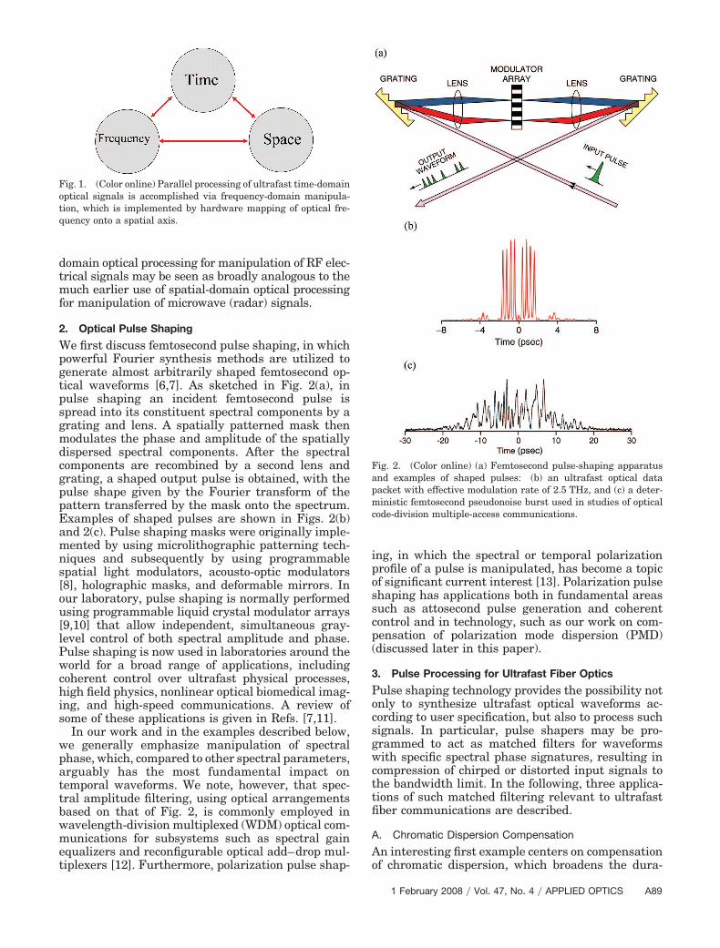
A block diagram of experiments demonstratingsuch dispersion compensation is shown in Fig. 3.Here a programmable pulse shaper was used to com-plement fiber dispersion compensation techniques inpropagating sub-500 fs pulses over optical fiber linksranging from 3 km in early experiments to 50 kmmost recently [14–16]. In all cases the link consistedof a length of standard single-mode fiber (SMF) con-catenated to an approximately matching length ofdispersion compensating fiber (DCF). Since SMF andDCF have dispersion with opposite signs at the op-erating wavelength, the fiber lengths can be adjustedto cancel all of the lowest order dispersion (i.e., phasevarying quadratically with frequency). In addition,since the derivatives of the dispersion with respect tofrequency also have opposite signs, the dispersionslope (i.e., cubic spectral phase variations) can bepartially compensated. In the experiments in Ref.[16], �460 fs input pulses at 1542 nm center wave-length are first broadened ten thousand times to�5 ns in propagating through the SMF, then recom-pressed by the DCF to within a factor of 2 of the inputpulse duration. Intensity cross-correlation measure-ments of the input pulse and output pulse after 50 kmfiber propagation are shown in Figs. 4(a) and 4(b),respectively. The remaining broadening and distor-tion of the output pulse are characteristic of cubicspectral phase variation. At this point the pulseshaper is used to apply a spectral phase function thatis equal and opposite to the estimated residual phasevariation. Both the actual applied phase function,which is a cubic function modulo 2� [Fig. 4(e)], as well
as the unwrapped version showing a continuous cubicphase [Fig. 4(d)], are plotted for purposes of illustra-tion. Application of the inverse spectral phase func-tion results in a completely recompressed pulse withessentially the original pulse duration ��470 fs� andno observable distortion [Fig. 4(c)]. Thus, in theseexperiments all-fiber techniques are used for coarsedispersion compensation, while a programmablepulse shaper is used as a spectral phase equalizerto fine tune away any remaining dispersion. In acompletely analogous fashion, programmable pulseshapers are now used extensively in compensation ofresidual dispersion in chirped pulse amplifier sys-tems and in few-cycle pulse generation.
B. Polarization-Mode Dispersion Compensation
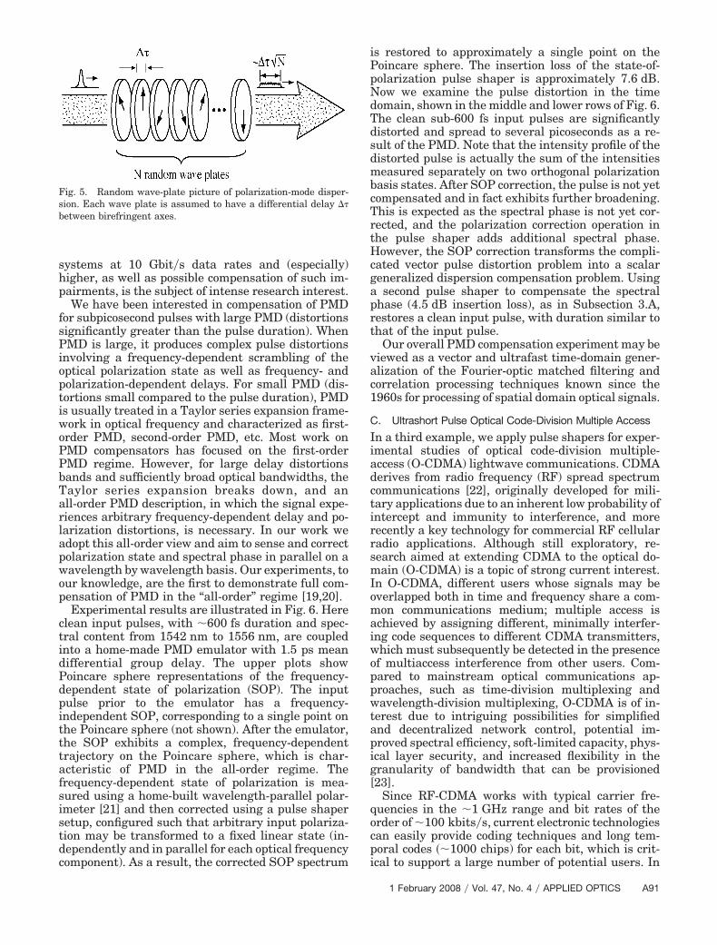
We have also performed a series of experiments inwhich a pulse shaper is used to compensate forpolarization-mode dispersion (PMD) in optical fiber.PMD arises from small and essentially random bire-fringences in single-mode optical fiber [17,18]. Someof the basics of PMD may be understood on the basisof a random wave plate model, illustrated in Fig. 5.Here each wave plate is assumed to have a differen-tial delay �� between its birefringent axes, and dif-ferent wave plates are assumed to have randomrotation angles. The delay experienced by an inputsignal depends on the input polarization and experi-ences essentially a random walk process. The meandifferential group delay observed at the output scalesas ���N, where N is the number of wave plates. Thiscorresponds to the finding that in real fibers, themean differential group delay contributed by PMDscales as the square root of fiber length. PMD-induced impairments of optical fiber transmission
Fig. 3. (Color online) Block diagram of femtosecond dispersioncompensation experiments in which a pulse shaper functions as aspectral phase equalizer.
Fig. 4. Distortionless transmission over 50 km fiber via spectralphase equalization. Intensity correlation measurements of (a) in-put pulse, (b) distorted pulse after propagation through 50 km fiberand partial compensation by dispersion compensating fiber, and (c)restored pulse after spectral phase equalization in a pulse shaper.(d) Unwrapped and (e) actual spectral phase profile programmedonto the liquid crystal modulator.
A90 APPLIED OPTICS � Vol. 47, No. 4 � 1 February 2008
systems at 10 Gbit�s data rates and (especially)higher, as well as possible compensation of such im-pairments, is the subject of intense research interest.
We have been interested in compensation of PMDfor subpicosecond pulses with large PMD (distortionssignificantly greater than the pulse duration). WhenPMD is large, it produces complex pulse distortionsinvolving a frequency-dependent scrambling of theoptical polarization state as well as frequency- andpolarization-dependent delays. For small PMD (dis-tortions small compared to the pulse duration), PMDis usually treated in a Taylor series expansion frame-work in optical frequency and characterized as first-order PMD, second-order PMD, etc. Most work onPMD compensators has focused on the first-orderPMD regime. However, for large delay distortionsbands and sufficiently broad optical bandwidths, theTaylor series expansion breaks down, and anall-order PMD description, in which the signal expe-riences arbitrary frequency-dependent delay and po-larization distortions, is necessary. In our work weadopt this all-order view and aim to sense and correctpolarization state and spectral phase in parallel on awavelength by wavelength basis. Our experiments, toour knowledge, are the first to demonstrate full com-pensation of PMD in the “all-order” regime [19,20].
Experimental results are illustrated in Fig. 6. Hereclean input pulses, with �600 fs duration and spec-tral content from 1542 nm to 1556 nm, are coupledinto a home-made PMD emulator with 1.5 ps meandifferential group delay. The upper plots showPoincare sphere representations of the frequency-dependent state of polarization (SOP). The inputpulse prior to the emulator has a frequency-independent SOP, corresponding to a single point onthe Poincare sphere (not shown). After the emulator,the SOP exhibits a complex, frequency-dependenttrajectory on the Poincare sphere, which is char-acteristic of PMD in the all-order regime. Thefrequency-dependent state of polarization is mea-sured using a home-built wavelength-parallel polar-imeter [21] and then corrected using a pulse shapersetup, configured such that arbitrary input polariza-tion may be transformed to a fixed linear state (in-dependently and in parallel for each optical frequencycomponent). As a result, the corrected SOP spectrum
is restored to approximately a single point on thePoincare sphere. The insertion loss of the state-of-polarization pulse shaper is approximately 7.6 dB.Now we examine the pulse distortion in the timedomain, shown in the middle and lower rows of Fig. 6.The clean sub-600 fs input pulses are significantlydistorted and spread to several picoseconds as a re-sult of the PMD. Note that the intensity profile of thedistorted pulse is actually the sum of the intensitiesmeasured separately on two orthogonal polarizationbasis states. After SOP correction, the pulse is not yetcompensated and in fact exhibits further broadening.This is expected as the spectral phase is not yet cor-rected, and the polarization correction operation inthe pulse shaper adds additional spectral phase.However, the SOP correction transforms the compli-cated vector pulse distortion problem into a scalargeneralized dispersion compensation problem. Usinga second pulse shaper to compensate the spectralphase (4.5 dB insertion loss), as in Subsection 3.A,restores a clean input pulse, with duration similar tothat of the input pulse.
Our overall PMD compensation experiment may beviewed as a vector and ultrafast time-domain gener-alization of the Fourier-optic matched filtering andcorrelation processing techniques known since the1960s for processing of spatial domain optical signals.
C. Ultrashort Pulse Optical Code-Division Multiple Access
In a third example, we apply pulse shapers for exper-imental studies of optical code-division multiple-access (O-CDMA) lightwave communications. CDMAderives from radio frequency (RF) spread spectrumcommunications [22], originally developed for mili-tary applications due to an inherent low probability ofintercept and immunity to interference, and morerecently a key technology for commercial RF cellularradio applications. Although still exploratory, re-search aimed at extending CDMA to the optical do-main (O-CDMA) is a topic of strong current interest.In O-CDMA, different users whose signals may beoverlapped both in time and frequency share a com-mon communications medium; multiple access isachieved by assigning different, minimally interfer-ing code sequences to different CDMA transmitters,which must subsequently be detected in the presenceof multiaccess interference from other users. Com-pared to mainstream optical communications ap-proaches, such as time-division multiplexing andwavelength-division multiplexing, O-CDMA is of in-terest due to intriguing possibilities for simplifiedand decentralized network control, potential im-proved spectral efficiency, soft-limited capacity, phys-ical layer security, and increased flexibility in thegranularity of bandwidth that can be provisioned[23].
Since RF-CDMA works with typical carrier fre-quencies in the �1 GHz range and bit rates of theorder of �100 kbits�s, current electronic technologiescan easily provide coding techniques and long tem-poral codes ��1000 chips) for each bit, which is crit-ical to support a large number of potential users. In
Fig. 5. Random wave-plate picture of polarization-mode disper-sion. Each wave plate is assumed to have a differential delay ��between birefringent axes.
1 February 2008 � Vol. 47, No. 4 � APPLIED OPTICS A91

addition, the system bit error rate requirement isusually not so strict for RF-CDMA. In contrast, theneed to perform encoding and decoding for O-CDMAposes one immediate challenge both because of theoptical carrier frequency and the much higher bitrates (multiple Gbits�s per user), which already ap-proaches the limit of electronic processing. Therefore,innovative all-optical processing technologies areneeded.
One of the earliest approaches to achieve encodingand decoding at the high rates needed for opticalcommunications is spectral phase encoding, first an-alyzed in Ref. [24]. Here a pulse shaper is used toimpart a spectral phase code onto the optical spec-trum. For the case of a pseudorandom phase code,this transforms a bandwidth-limited input pulse intoa pseudonoise burst in time, such as shown in Fig.2(c). At the receiver a second pulse shaper can be
programmed with a conjugate phase code, such thatincoming signals with the matching code are recom-pressed (decoded) into short pulses. Multiaccess in-terference from other users with different codes isnot correctly decoded and hence remains in the formof low intensity pseudonoise signals. The desired(matching) signal can then be picked out on the basisof its higher peak intensity.
References [25,26] provide recent reviews ofO-CMDA, with an emphasis on experimentalprogress in spectral phase encoded approaches. Fig-ure 7 shows the schematic experimental setup forfour-user O-CDMA data transmission experiments at2.5 Gbits�s and 10 Gbits�s per user performed in theauthor’s laboratory at Purdue University [27,28]. Anactively mode-locked fiber laser followed by a disper-sion decreasing fiber soliton compressor producingnearly transform-limited �0.4 ps pulses at 10 GHz
Fig. 6. Data on all-order PMD compensation. The top row displays SOP versus wavelength before and after PMD compensation. Themiddle and the bottom rows show the time-domain waveforms at the input, and after each PMD compensation step.
A92 APPLIED OPTICS � Vol. 47, No. 4 � 1 February 2008
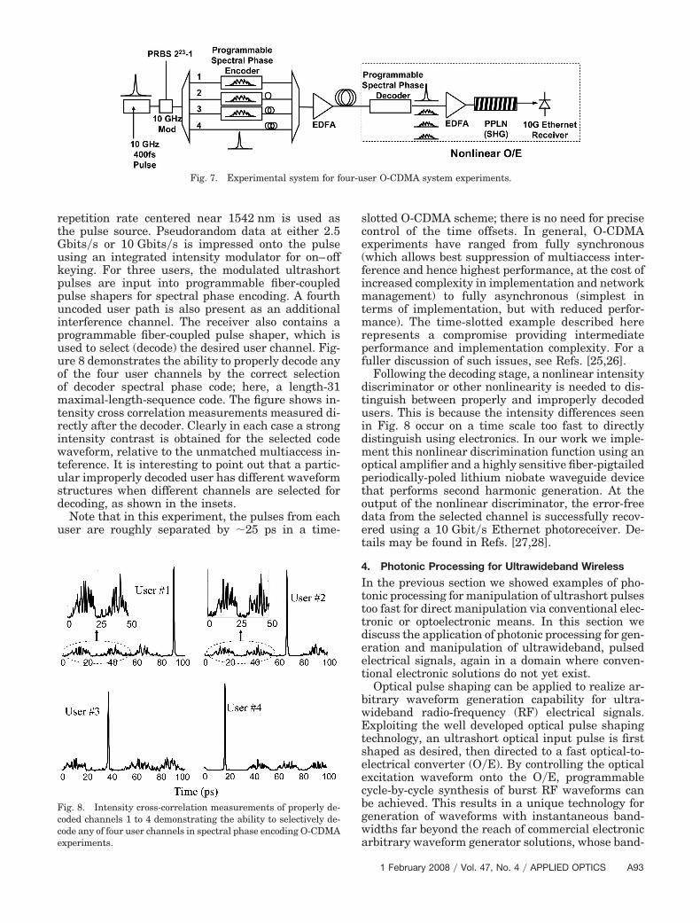
repetition rate centered near 1542 nm is used asthe pulse source. Pseudorandom data at either 2.5Gbits�s or 10 Gbits�s is impressed onto the pulseusing an integrated intensity modulator for on–offkeying. For three users, the modulated ultrashortpulses are input into programmable fiber-coupledpulse shapers for spectral phase encoding. A fourthuncoded user path is also present as an additionalinterference channel. The receiver also contains aprogrammable fiber-coupled pulse shaper, which isused to select (decode) the desired user channel. Fig-ure 8 demonstrates the ability to properly decode anyof the four user channels by the correct selectionof decoder spectral phase code; here, a length-31maximal-length-sequence code. The figure shows in-tensity cross correlation measurements measured di-rectly after the decoder. Clearly in each case a strongintensity contrast is obtained for the selected codewaveform, relative to the unmatched multiaccess in-teference. It is interesting to point out that a partic-ular improperly decoded user has different waveformstructures when different channels are selected fordecoding, as shown in the insets.
Note that in this experiment, the pulses from eachuser are roughly separated by �25 ps in a time-
slotted O-CDMA scheme; there is no need for precisecontrol of the time offsets. In general, O-CDMAexperiments have ranged from fully synchronous(which allows best suppression of multiaccess inter-ference and hence highest performance, at the cost ofincreased complexity in implementation and networkmanagement) to fully asynchronous (simplest interms of implementation, but with reduced perfor-mance). The time-slotted example described hererepresents a compromise providing intermediateperformance and implementation complexity. For afuller discussion of such issues, see Refs. [25,26].
Following the decoding stage, a nonlinear intensitydiscriminator or other nonlinearity is needed to dis-tinguish between properly and improperly decodedusers. This is because the intensity differences seenin Fig. 8 occur on a time scale too fast to directlydistinguish using electronics. In our work we imple-ment this nonlinear discrimination function using anoptical amplifier and a highly sensitive fiber-pigtailedperiodically-poled lithium niobate waveguide devicethat performs second harmonic generation. At theoutput of the nonlinear discriminator, the error-freedata from the selected channel is successfully recov-ered using a 10 Gbit�s Ethernet photoreceiver. De-tails may be found in Refs. [27,28].
4. Photonic Processing for Ultrawideband Wireless
In the previous section we showed examples of pho-tonic processing for manipulation of ultrashort pulsestoo fast for direct manipulation via conventional elec-tronic or optoelectronic means. In this section wediscuss the application of photonic processing for gen-eration and manipulation of ultrawideband, pulsedelectrical signals, again in a domain where conven-tional electronic solutions do not yet exist.
Optical pulse shaping can be applied to realize ar-bitrary waveform generation capability for ultra-wideband radio-frequency (RF) electrical signals.Exploiting the well developed optical pulse shapingtechnology, an ultrashort optical input pulse is firstshaped as desired, then directed to a fast optical-to-electrical converter (O�E). By controlling the opticalexcitation waveform onto the O�E, programmablecycle-by-cycle synthesis of burst RF waveforms canbe achieved. This results in a unique technology forgeneration of waveforms with instantaneous band-widths far beyond the reach of commercial electronicarbitrary waveform generator solutions, whose band-
Fig. 7. Experimental system for four-user O-CDMA system experiments.
Fig. 8. Intensity cross-correlation measurements of properly de-coded channels 1 to 4 demonstrating the ability to selectively de-code any of four user channels in spectral phase encoding O-CDMAexperiments.
1 February 2008 � Vol. 47, No. 4 � APPLIED OPTICS A93
widths are limited to 1–2 GHz. Different choices ofpulse shaper configurations, coupled with differentchoices of O�E converter technologies, has alloweddemonstrations of waveform generation from theGHz to the THz. Hence this approach is scalable overseveral orders of magnitude in RF frequency. Re-views are presented in Refs. [29,30].
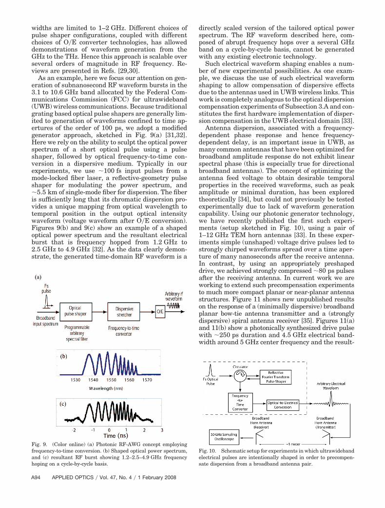
As an example, here we focus our attention on gen-eration of subnanosecond RF waveform bursts in the3.1 to 10.6 GHz band allocated by the Federal Com-munications Commission (FCC) for ultrawideband(UWB) wireless communications. Because traditionalgrating based optical pulse shapers are generally lim-ited to generation of waveforms confined to time ap-ertures of the order of 100 ps, we adopt a modifiedgenerator approach, sketched in Fig. 9(a) [31,32].Here we rely on the ability to sculpt the optical powerspectrum of a short optical pulse using a pulseshaper, followed by optical frequency-to-time con-version in a dispersive medium. Typically in ourexperiments, we use �100 fs input pulses from amode-locked fiber laser, a reflective-geometry pulseshaper for modulating the power spectrum, and�5.5 km of single-mode fiber for dispersion. The fiberis sufficiently long that its chromatic dispersion pro-vides a unique mapping from optical wavelength totemporal position in the output optical intensitywaveform (voltage waveform after O�E conversion).Figures 9(b) and 9(c) show an example of a shapedoptical power spectrum and the resultant electricalburst that is frequency hopped from 1.2 GHz to2.5 GHz to 4.9 GHz [32]. As the data clearly demon-strate, the generated time-domain RF waveform is a
directly scaled version of the tailored optical powerspectrum. The RF waveform described here, com-posed of abrupt frequency hops over a several GHzband on a cycle-by-cycle basis, cannot be generatedwith any existing electronic technology.
Such electrical waveform shaping enables a num-ber of new experimental possibilities. As one exam-ple, we discuss the use of such electrical waveformshaping to allow compensation of dispersive effectsdue to the antennas used in UWB wireless links. Thiswork is completely analogous to the optical dispersioncompensation experiments of Subsection 3.A and con-stitutes the first hardware implementation of disper-sion compensation in the UWB electrical domain [33].
Antenna dispersion, associated with a frequency-dependent phase response and hence frequency-dependent delay, is an important issue in UWB, asmany common antennas that have been optimized forbroadband amplitude response do not exhibit linearspectral phase (this is especially true for directionalbroadband antennas). The concept of optimizing theantenna feed voltage to obtain desirable temporalproperties in the received waveforms, such as peakamplitude or minimal duration, has been exploredtheoretically [34], but could not previously be testedexperimentally due to lack of waveform generationcapability. Using our photonic generator technology,we have recently published the first such experi-ments (setup sketched in Fig. 10), using a pair of1–12 GHz TEM horn antennas [33]. In these exper-iments simple (unshaped) voltage drive pulses led tostrongly chirped waveforms spread over a time aper-ture of many nanoseconds after the receive antenna.In contrast, by using an appropriately preshapeddrive, we achieved strongly compressed �80 ps pulsesafter the receiving antenna. In current work we areworking to extend such precompensation experimentsto much more compact planar or near-planar antennastructures. Figure 11 shows new unpublished resultson the response of a (minimally dispersive) broadbandplanar bow-tie antenna transmitter and a (stronglydispersive) spiral antenna receiver [35]. Figures 11(a)and 11(b) show a photonically synthesized drive pulsewith �250 ps duration and 4.5 GHz electrical band-width around 5 GHz center frequency and the result-
Fig. 9. (Color online) (a) Photonic RF-AWG concept employingfrequency-to-time conversion. (b) Shaped optical power spectrum,and (c) resultant RF burst showing 1.2–2.5–4.9 GHz frequencyhoping on a cycle-by-cycle basis.
Fig. 10. Schematic setup for experiments in which ultrawidebandelectrical pulses are intentionally shaped in order to precompen-sate dispersion from a broadband antenna pair.
A94 APPLIED OPTICS � Vol. 47, No. 4 � 1 February 2008
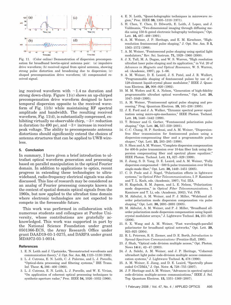
ing received waveform with �1.4 ns duration andstrong down-chirp. Figure 11(c) shows an up-chirpedprecompensation drive waveform designed to havetemporal dispersion opposite to the received wave-form of Fig. 11(b) while maintaining RF spectralamplitude and bandwidth. The resulting receivedwaveform, Fig. 11(d), is substantially compressed, ex-hibiting virtually no observable chirp, �3� reductionin duration (to 490 ps), and �3� increase in receivedpeak voltage. The ability to precompensate antennadistortions should significantly extend the choices ofantenna structures that can be applied to UWB wire-less.
5. Conclusion
In summary, I have given a brief introduction to ul-trafast optical waveform generation and processingbased on parallel manipulation in the optical Fourierdomain. In addition to applications to optics, recentprogress in extending these technologies to ultra-wideband, radio-frequency electrical signals was alsodiscussed. This line of research may be considered asan analog of Fourier processing concepts known inthe context of spatial domain optical signals from the1960s, but now applied to the ultrafast time domainwhere electronic technologies are not expected tocompete in the foreseeable future.
This work was performed in collaboration withnumerous students and colleagues at Purdue Uni-versity, whose contributions are gratefully ac-knowledged. This work was supported in part bythe National Science Foundation under grant0501366-ECS, the Army Research Office undergrant DAAD19-03-1-0275, and DARPA under grantMDA972-03-1-0014.
References1. E. N. Leith and J. Upatnieks, “Reconstructed wavefronts and
communication theory,” J. Opt. Soc. Am. 52, 1123–1130 (1962).2. L. J. Cutrona, E. N. Leith, C. J. Palermo, and L. J. Porcello,
“Optical-data processing and filtering systems,” IRE Trans.Inf. Theor. 6, 386–400 (1960).
3. L. J. Cutrona, E. N. Leith, L. J. Porcello, and W. E. Vivian,“On application of coherent optical processing techniques tosynthetic-aperture radar,” Proc. IEEE 54, 1026–1032 (1966).
4. E. N. Leith, “Quasi-holographic techniques in microwave re-gion,” Proc. IEEE 59, 1305–1318 (1971).
5. H. Chen, Y. Chen, D. Dilworth, E. Leith, J. Lopez, and J.Valdmanis, “Two-dimensional imaging through diffusing me-dia using 150-fs gated electronic holography techniques,” Opt.Lett. 16, 487–489 (1991).
6. A. M. Weiner, J. P. Heritage, and E. M. Kirschner, “High-resolution femtosecond pulse shaping,” J. Opt. Soc. Am. B 5,1563–1572 (1988).
7. A. M. Weiner, “Femtosecond pulse shaping using spatial lightmodulators,” Rev. Sci. Instrum. 71, 1929–1960 (2000).
8. J. X. Tull, M. A. Dugan, and W. S. Warren, “High resolutionultrafast laser pulse shaping and its application,” in Vol. 20 ofAdvances in Magnetic and Optical Resonance, W. S. Warren,ed. (Academic, 1997), pp. 1–66.
9. A. M. Weiner, D. E. Leaird, J. S. Patel, and J. R. Wullert,“Programmable shaping of femtosecond pulses by use of a128-element liquid-crystal phase modulator,” IEEE J. Quan-tum Electron. 28, 908–920 (1992).
10. M. M. Wefers and K. A. Nelson, “Generation of high-fidelityprogrammable ultrafast optical waveforms,” Opt. Lett. 20,1047–1049 (1995).
11. A. M. Weiner, “Femtosecond optical pulse shaping and pro-cessing,” Prog. Quantum Electron. 19, 161–238 (1995).
12. J. E. Ford and J. A. Walker, “Dynamic spectral power equal-ization using micro-opto-mechanics,” IEEE Photon. Technol.Lett. 10, 1440–1442 (1998).
13. T. Brixner and G. Gerber, “Femtosecond polarization pulseshaping,” Opt. Lett. 26, 557–559 (2001).
14. C.-C. Chang, H. P. Sardesai, and A. M. Weiner, “Dispersion-free fiber transmission for femtosecond pulses using adispersion-compensating fiber and a programmable pulseshaper,” Opt. Lett. 23, 283–285 (1998).
15. S. Shen and A. M. Weiner, “Complete dispersion compensationfor 400-fs pulse transmission over 10-km fiber link using dis-persion compensating fiber and spectral phase equalizer,”IEEE Photon. Technol. Lett. 11, 827–829 (1999).
16. Z. Jiang, S. D. Yang, D. E. Leaird, and A. M. Weiner, “Fullydispersion-compensated �500 fs pulse transmission over 50 kmsingle-mode fiber,” Opt. Lett. 30, 1449–1451 (2005).
17. C. D. Poole and J. Nagel, “Polarization effects in lightwavesystems,” in Optical Fiber Telecommunications, I. P. Kaminowand T. L. Koch, eds. (Academic, 1997), Vol. IIIA.
18. H. Kogelnik, R. M. Jopson, and L. E. Nelson, “Polarization-mode dispersion,” in Optical Fiber Telecommunications, I.Kaminow and T. Li, eds. (Academic, 2002), Vol. IVB.
19. M. Akbulut, A. M. Weiner, and P. J. Miller, “Wideband all-order polarization mode dispersion compensation via pulseshaping,” Opt. Lett. 30, 2691–2693 (2005).
20. M. Akbulut, A. M. Weiner, and P. J. Miller, “Broadband all-order polarization mode dispersion compensation using liquid-crystal modulator arrays,” J. Lightwave Technol. 24, 251–261(2006).
21. S. X. Wang and A. M. Weiner, “Fast wavelength-parallelpolarimeter for broadband optical networks,” Opt. Lett. 29,923–925 (2004).
22. R. L. Peterson, R. E. Ziemer, and D. E. Borth, Introduction toSpread-Spectrum Communications (Prentice-Hall, 1995).
23. J. Shah, “Optical code division multiple access,” Opt. Photon.News 14(4), 42–47 (2003).
24. J. A. Salehi, A. M. Weiner, and J. P. Heritage, “Coherentultrashort light pulse code-division multiple access communi-cation systems,” J. Lightwave Technol. 8, 478 (1990).
25. A. M. Weiner, Z. Jiang, and D. E. Leaird, “Spectrally phasecoded O-CDMA,” J. Opt. Netw. 6, 728–755 (2007).
26. J. P. Heritage and A. M. Weiner, “Advances in spectral opticalcode-division multiple-access communications,” IEEE J. Sel.Top. Quantum Electron. 13, 1351–1369 (2007).
Fig. 11. (Color online) Demonstration of dispersion precompen-sation for broadband bowtie-spiral antenna pair: (a) impulsivedrive waveform; (b) received signal from spiral antenna, showingstrong pulse distortion and broadening due to dispersion; (c)shaped precompensation drive waveform; (d) compensated re-ceived signal.
1 February 2008 � Vol. 47, No. 4 � APPLIED OPTICS A95
27. Z. Jiang, D. S. Seo, S. D. Yang, D. E. Leaird, R. V. Roussev, C.Langrock, A. M. Fejer, and A. M. Weiner, “Four-user, 2.5-Gb�s,spectrally coded OCDMA system demonstration using low-power nonlinear processing,” J. Lightwave Technol. 23, 143–158 (2005).
28. Z. Jiang, D. Seo, S. Yang, D. E. Leaird, R. V. Roussev, C.Langrock, M. M. Fejer, and A. M. Weiner, “Four-user 10-Gb�sspectrally phase-coded O-CDMA system operating at similarto 30 fJ�bit,” IEEE Photon. Technol. Lett. 17, 705–707(2005).
29. J. D. McKinney, I.-S. Lin, and A. M. Weiner, “Ultrabroadbandarbitrary electromagnetic waveform synthesis,” Opt. Photon.News 17(4), 24–29 (2006).
30. J. D. McKinney and A. M. Weiner, “Photonic synthesis ofultrabroadband arbitrary electromagnetic waveforms,” inAdvances in Microwave Photonics, C. H. Lee, ed. (CRC Press,2006).
31. J. Chou, Y. Han, and B. Jalali, “Adaptive RF-photonic arbi-
trary waveform generator,” IEEE Photon. Technol. Lett. 15,581–583 (2003).
32. I. S. Lin, J. D. McKinney, and A. M. Weiner, “Photonic syn-thesis of broadband microwave arbitrary waveforms applica-ble to ultra-wideband communication,” IEEE MicrowaveWireless Components Lett. 15, 226–228 (2005).
33. J. D. McKinney and A. M. Weiner, “Compensation of the ef-fects of antenna dispersion on UWB waveforms via opticalpulse-shaping techniques,” IEEE Trans. Microwave TheoryTech. 54, 1681–1686 (2006).
34. D. M. Pozar, “Waveform optimizations for ultrawideband radiosystems,” IEEE Trans. Antennas Propag. 51, 2335–2345(2003).
35. J. D. McKinney, D. Peroulis, and A. M. Weiner, “Disper-sion limitations of ultrawideband wireless links and theircompensation via photonically-enabled arbitrary waveformgeneration,” IEEE Trans. Microwave Theory Tech. (submit-ted).
A96 APPLIED OPTICS � Vol. 47, No. 4 � 1 February 2008


![1 Careful study of Ultrafast Magneto-Optics ITOH Lab. Yoshitaka Sakamoto ( 坂本 圭隆 ) [Referenece] “Ultrafast Magneto-Optics in Nickel: Magnetism or Optics?”](https://img.dokumen.tips/doc/110x75/56649f435503460f94c64103/1-careful-study-of-ultrafast-magneto-optics-itoh-lab-yoshitaka-sakamoto-.jpg)