Embed Size (px)
Citation preview

FORTRAN ASSEMBLY PROGRAM (FAP) for the IBM 709/7090
The original FORTRAN Assembly Program was conceived by David E. Ferguson and coded by Mr. Ferguson and Donald P. Moore at the Western Data Processing Center, University of California at Los Angeles. Several features present in this version of FAP were added by Mr. Moore. This bulletin was written by Mr. Moore and edited by Richard H. Hill and Joseph Annino, of the Western Data Processing Center. It is published by IBM because of its importance to all 709 FORTRAN users. IBM wishes to assist its customers in obtaining a maximum of information concerning 709 FORTRAN and believes this bulletin for the FAP system essential to all 709/7090 installations.
IBM would like to take this opportunity to thank Mr. Moore, Mr. Hill, and Mr. Annino and the other members of the Western Data Processing Center who gave their time and efforts -
to this significant contribution to 709 FORTRAN.
This edition, J28-6098-1, supersedes but does not obsolete the pevious edition, J28-6098.
Two types of changes have been made:
1. Changes to the previous edition. These have been incorporated in the text, paragraphs and pages affected are indicated by the symbol " " in the margin.
2. Additions to the previous manual. These have been grouped together in the Addenda beginning on page 78.
@ 1960, 1961 by International Business Machines Corporation
Address comments regarding this publication to Programming Systems Publications, IBM Corporation, 1271 Avenue of the Americas, New York 20, N. Y.


CONTENTS Page
. . . . . . . . . . . . . . . . . . . . . . . . . INTRODUCTION 1
. . . . . . . . . . . . . . . . . . . PART I: THE FAP LANGUAGE 2
. . . . . . . . . . . . . . . . . . . Elements of the Language 2 . . . . . . . . . . . . . . . . . . . . Symbolic Card Format 2
. . . . . . . . . . . . . . . . . . . . . . . . . Symbols 2 . . . . . . . . . . . . . . . . . . . . . . . Symbol Definition 3 . . . . . . . . . . . . . . . . . . . . . . Types of Symbols 3
. . . . . . . . . . . . . . . . . . . . . . . . . Relocation 3 . . . . . . . . . . . . . . . . . . . . . Elements and T e r m s 4
l l * r r as an Element . . . . . . . . . . . . . . . . . . 5 Expressions . . . . . . . . . . . . . . . . . . . 5 Evaluation of Expressions . . . . . . . . . . . . . . . 5
. . . . . . . . . . . . . . . . . . . . Types of Expressions 6 Boolean Expressions . . . . . . . . . . . . . . . . . . . . . 9
. . . . . . . . . . . . . . . . . . . . . . . Location Field 11 . . . . . . . . . . . . . . . . . . . . . . . . *(Remarks) 11
. . . . . . . . . . . . . . . . . . . . . . . Operation Field 11 . . . . . . . . . . . . . . . . . . . . . Indirect Addressing 12
. . . . . . . . . . . . . . . . . . . . . . . Variable Field 12 . . . . . . . . . . . . . . . . . . . . . . . . . . Literals 13
. . . . . . . . . . . PART 11: OPERATIONS AND PSEUDO-OPEJUTIONS 15
Chapter 1 . 709 MACHINE OPERATIONS . . . . . . . . . . . . . 15
Chapter 2 . EXTENDED MACHINE OPERATIONS . . . . . . . 16 . . . . . . . . . . . . . . . . . . . SenseOperat ions 16
. . . . . . . . . . . . . . . . . . . . Prefix Codes 18 . . . . . . . . . . . . . . Select and Related Operations 19
Chapter 3 . VARIABLE-CHANNEL TAPE OPERATION . . . . 21
. . . . . . . . . . . . . . . Chapter 4 . PSEUDO-OPERATIONS 24
Chapter 5 . PSEUDO-OPERATIONS REQUIRED IN EVERY ASSEMBLY . 26 . . . . . . . . . . . . . . . . . . . . . . . COUNT 26 . . . . . . . . . . . . . . . . . . . . . . . END 26
Chapter 6 . PREVIOUSLY-DEFINED SYMBOLS . . . . . . . . . 26
Chapter 7 . SYMBOL-DEFINING PSEUDO-OPERATIONS . . 27 . . . . . . . . . . . . . . . . . . . . EQUandSYN 27
. . . . . . . . . . . . . . . . . . . . . . . BOOL 28 . . . . . . . . . . . . . . . . . . . . . . TAPENO 28

Chapter 8 . STORAGE-ALLOCATING PSEUDO-OPERATIONS . . 29 . . . . . . . . . . . . . . . . Phase Relocation E r r o r s 29
. . . . . . . . . . . . . . . . . . . . . . . . BSS 29
. . . . . . . . . . . . . . . . . . . . . . . . BES 31 . . . . . . . . . . . . . . . . . . . . . . COMMON 32
Chapter 9 . DATA-GENERATING PSEUDO-OPERATIONS . . . . . . . 33 . . . . . . . . . . . . . . . . . . . . . . . . OCT 33
Decimal -Data Items . . . . . . . . . . . . . . . . . . . 34 . . . . . . . . . . . . . . . . . . . . . . . . DEC 37 . . . . . . . . . . . . . . . . . . . . . . . . BCI 38 . . . . . . . . . . . . . . . . . . . . . . . . BCD 40 . . . . . . . . . . . . . . . . . . . . . . . . VFD 40 . . . . . . . . . . . . . . . . . . . . . . . . ETC 43 . . . . . . . . . . . . . . . . . . . . . . . . DUP 44
Chapter 10 . PROGRAM-LINKING PSEUDO-OPERATIONS . . . . . 46 . . . . . . . . . . . . . . . . . . . . . . . ENTRY 46 . . . . . . . . . . . . . . . . . . . . . . . CALL 48
. . . . . . . . . . . . . Standard E r r o r Procedure Option 49
. . . . . . . . . . . . . Subroutine Reference Using lV$ll 51 . . . . . . . . . . . . . . . . . . . . . . . IFEOF 53
Chapter 11 . ABSOLUTE ASSEMBLIES . . . . . . . . . . . 53 . . . . . . . . . . . . . . . . . . . . . . . . ABS 53 . . . . . . . . . . . . . . . . . . . . . . . . FUL 55 . . . . . . . . . . . . . . . . . . . . . . . . ORG 55
. . . . . . . . . . . . . . . . . . . . . . . HEAD 56 . . . . . . . . . . . . . . . . . . . . . . . . HED 59
. . . . . . . . . . . . . . . . . . . . . . TCD . , 59 END (In Absolute Assemblies) . . . . . . . . . . . . . 59
. . . . . . . . . . . . . . Chapter 12 . THE ASSEMBLY LISTING 60 . . . . . . . . . . . . . . . . . . . . Page Heading 61
Chapter 13 . LIST-CONTROL PSEUDO-OPERATIONS REM . . . . . . . . . . . . . . SPACE . . . . . . . . . . . . . . . EJECT . . . . . . . . . . . . . . .
. . . . . . . . . . . . . . . UNLIST LIST . . . . . . . . . . . . . . .
. . . . . . . . . . . . . . . TITLE DETAIL . . . . . . . . . . . . . .
Chapter 14 . BINARY OUTPUT FROM THE ASSEMBLER . . . . . . . 64 . . . . . . . . . . . . . . . . . . Relocatable Output 64
. . . . . . . . . . . . . . . . . Absolute Row Output 64 Absolute Column Output . . . . . . . . . . . . . . 65
. . . . . . . . . . . . . . . . . . . . "Full" Output 65

. . . . . . . . . . . . . . . . . PARTIII: GENERALINFORMATION 66
Chapter 1 . SUBROUTINES . . . . . . . . . . . . . . . . . . 66 . . . . . . . . . . . . . . Open and Closed Subroutines 66
. . . . . . . . . . . . . . . . . . . . . Linkages 66 . . . . . . . . . . . . . . . . . . Calling Sequences 67
FORTRANLinkagesandCalling&equences . . . . . . . . . 68 . . . . . . . . . . . . . . . . . . . . Segmentation 69
. . . . . . . . . . . . . . . . . . . Common Storage 69 . . . . . . . . . . . . . . . . . . Relocatable Binary 70
. . . . . . . . . . . . . . . . . . . Transfer Vector 71
Chapter 2 . A BRIEF DESCRIPTION OF THE ASSEMBLY PROCESS . . 71
Chapter 3 . THE FAP BCD CHARACTER CODE . . . . . . . . 74
. . . . . . . . . . . . . . . . . . . . . . . . . . . . INDEX 76


6 INTRODUCTION
A 709 machine-language program is a sequence of binary numbers which instructs the 709 to perform a particular task. A symbolic-language program is a representation of a machine-language program in a form which is more convenient to human beings. The symbolic language is sufficiently like machine language to permit the programmer to utilize all the facilities of the computer which would be available to him i f he were to code directly in machine language. An assembler is a programming aid which translates symbolic -language programs into machine-language programs.
An assembler resembles a compiler (such as FORTRAN) in that it produces machine-language programs. It differs from a compiler in that the symbolic language used with an assembler is closely related to the language used by the computer, while the source language used with a compiler resembles the technical language in which problems are stated by human beings.
Compilers have several advantages over assemblers. The language used with a compiler is easier to learn and easier to use; the programmer using a compiler usually does not need an intimate knowledge of the inner workings of the computer. Programming is faster. Finally, the time required to obtain a finished, working program is greatly reduced, since there is less chance for the programmer to make a mistake, and since most mistakes which are made are detected by the compiler.
The assembler compensates for its disadvantages 9s compared to the compiler by offering the programmer a degree of flexibility not available with any present-day compiler.
FAP was created to provide a compromise between the convenience of a compiler and the flexibility of an assembler. Using FAP in conjunction with 709 FORTRAN in the IBM FORTRAN Monitor, a programmer may code the major part of his program in FORTRAN, and code FAP subroutines to accomplish those parts of the programming task for which FORTRAN is not suitable. Alternatively, the programmer may code the major part of the program in FAP, using FORTRAN subroutines for certain computational and input/output operations. For those tasks which must be coded entirely in symbolic language, FAP may be used to produce an "absolutev program which will operate independently of the Monitor.

PART 1 THE FAP LANGUAGE
Elements of FAP"is a fast, versatile, general purpose assembler for the IBM 709/7090 the Language written expressly for use within the IBM 709 FORTRAN Monitor. Originally
intended as a means for producing symbolic-language subroutines for FORTRAN programs, the facilities of FAP have been extended. FAP now allows complete flexibility of use for either independent operation of FAP programs or intercommunication with FORTRAN programs.
FAP incorporates all 709 machine language and extended operation codes described in the 709 Reference Manual (Form A22-6536), and also includes certain pseudo-operations which are described here.
Typically a symbolic instruction consists of four major divisions : location field, operation, field, variable field, and comment field.
The location field normally contains a name by which other instructions may refer to the instruction named. The operation field contains the name of the machine operation or pseudo-operation, and the variable field normally contains the location of the operand. The comments field exists solely for the convenience of the programmer and plays no part in directing the machine. The example below illustrates a typical instruction, showing use of the various fields.
* FOR REMARKS I I
ION OPERATION I ADDRESS, TAG, DECREMENT/COUNT COMMENTS I I
This instruction might be the first instruction of a routine entered by a transfer instruction whose variable field contains the address CASEB. The machine operation here is "Clear and Add, t f and the address of the operand is a storage location which is referred to as TMPX.
Symbolic Card Symbolic instructions are punched one per card in the SHARE 709 Symbolic Format Card format. The location field, which may be blank, occupies card
columns 1 - 6. Column 7 is always blank. The operation field begins in column 8 and is from three to seven characters in length. A blank column separates the operation field and the variable field, which may begin in column 12, but in no case may begin later than column 16. It is common for an installation to adopt a fixed column as the beginning of the variable field in all instructions. The variable field does not normally extend beyond column 71, and must be followed by a blank column to separate it from the comments field (except in the case of the BCI and BCD pseudo-operations). The comments field follows and extends through column 80. In the absence of a variable field, the comments field may not begin before column 17. Columns 7 3 -80 are commonly used for identification and serial numbering.
Symbols A symbol (also referred to by the terms "location symbol" and "symbolic address") is a string of from one to six non-blank characters, at least one of which is non-numeric, and none of which is among the following set of eight characters:

Symbol Definition
Types of Symbols
Relocation
+ (plus sign) $ (dollar sign) - (minus sign) = (equal sign) * (asterisk) (apostrophe) / (slash mark) , (comma)
For example,
are all legal symbols. A symbol is used as a name for a storage location, tape address, or other program parameter. (Experience has shown that fewer keypunch errors occur if all symbols are composed exclusively of alphabetic characters. )
A symbol i s defined in one of two ways:
1. By its appearance in the location field of some instruction, or
2. By its use as the name of a subprogram.
Every symbol used in the program must be defined exactly once. An error will be indicated by the assembler if any symbol is used but never defined, or if any symbol i s defined more than once.
The assembler recognizes three types of symbols. Every symbol - encountered in the assembly process will be classified according to type at the time it is defined. An absolute symbol refers to a fixed number, such as a tape address. An absolute symbol usually is not used to refer to a location in core storage. A common symbol refers to a location in common storage (see section describing the COMMON pseudo-operation). Any symbol that is not either absolute or common is classified as relocatable. In particular, a symbol which occurs in the location field of an instruction is a relocatable symbol, except for symbols occurring in the location fields of certain pseudo-operations.
When an absolute assembly has been specified by the use of the ABS pseudo- operation, all symbols are treated as absolute symbols.
0 Every program or subprogram produced by the FORTRAN Monitor System nominally begins in cell zero. Since a job to be executed may contain several subprograms, i t is obvious that they may not all be loaded into cells starting with cell zero. In fact, no program is ever loaded beginning at cell zero, but each program is relocated. The first program or subprogram is loaded into lower memory. Successive sub- programs are then loaded into memory, each beginning with the cell after the last cell of lower memory used by the preceding subprogram. The main program is loaded in the same way. When a particular pro- gram has been loaded, the address of the first word is called that program's load address.

Elements and Terms
Then the address actually occupied by a word of the program is the address assigned at assembly time - plus the load address. To keep the program self-consistent, the load address must be added to the addresses and decrements of many (but not all) of the instructions.
This process of conditionally adding the load address is performed by the loading program just prior to execution, and is called relocation. In relocating instructions, the loading program is guided by relocation indicator bits which were inserted when the program was compiled or assembled. References to common storage a re subject to a different type of relocation, controlled by Contr,ol Cards during loading.
A more extensive discussion of relocation may be found in Part 111.
In writing symbolic instructions, the programmer is concerned with the problem of building expressions to represent, in the case of the 709 machine instructions, the address , tag, and decrement portions of the instructions. Expressions a re also used in the variable fields of pseudo-instructions in accordance with the rules set forth in each specific case (see section on Operations and Pseudo- Operations ) .
Before discussing expressions, it is necessary to describe the building blocks used to construct them. These building blocks a re elements, terms, and operators.
The smallest components of an expression a re elements. An element is either a single symbol or a single integer less than 235. (The asterisk may also be used as an element; see below. ) Ah absolute, relocatable, or common symbol is regarded respectively as an absolute, relocatable, or common element. An integer i s always an absolute element.
A term is a string composed of elements and the operators:
* (multiplication) / (division)
A term may consist of a single element, two elements separated by 11*11 or "/11, three elements separated by two operators, etc. A term must begin with an element and end with an element. It i s not permissible to write two operators in succession or to write two elements in succession. Examples of terms a re
TMP*FUNC*TAXY FIRST/SCND*THRD*~ 3 6*4096 5 *X OFICA
Expressions
Evaluation of Expressions
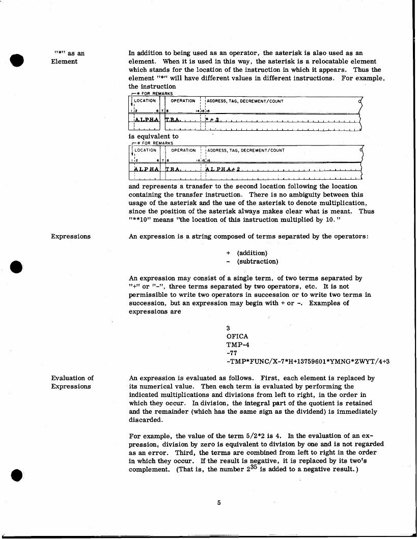
In addition to being used as an operator, the asterisk is also used as an element. When it is used in this way, the asterisk is a relocatable element which stands for the location of the instruction in which it appears. Thus the element l'*l' will have different values in different instructions. For example, the instruction
* FOR REMARKS
I I
is equivalent to * FOR REMARKS
I I
OPERATION I 1 ADDRESS, TAG, DECREMENT/COuNT I I
and represents a transfer to the second location following the location containing the transfer instruction. There is no ambiguity between this usage of the asterisk and the use of the asterisk to denote multiplication, since the position of the asterisk always makes clear what is meant. Thus "**1011 means "the location of this instruction multiplied by 10.
An expression i s a string composed of terms separated by the operators:
+ (additkon) - (subtraction)
An expression may consist of a single term, of two terms separated by '1+11 or "J1, three terms separated by two operators, etc. It is not permissible to write two operators in succession or to write two terms in succession, but an expression may begin with + or -. Examples of expressions are
I
3 OFICA TMP-4 -77 - T M P * F U N C / X - 7 * ~ + 1 3 7 5 9 6 0 1 * ~ ~ ~ ~ * ~ ~ ~ ~ / 4 + 3
An expression is evaluated as follows. First, each element is replaced by its numerical value. Then each term is evaluated by performing the indicated multiplications and divisions from left to right, in the order in which they occur. In division, the integral part of the quotient is retained and the remainder (which has the same sign as the dividend) is immediately discarded.
For example, the value of the term 5/2*2 is 4. In the evaluation of an ex- pression, division by zero is equivalent to division by one and is not regarded a s an error. Third, the terms are combined from left to right in the order in which they occur. If the result is negative, it is replaced by its two's complement. (That is , the number 235 is added to a negative result. )

Types of Expressions
Finally, this result is reduced modulo 215 (except in the variable field of a VFD or BOOL pseudo-operation); that is, only the rightmost 15 bits are retained.
Grouping of terms, by parentheses or otherwise, is not permitted, but this restriction may often be circumvented. For instance the product of A with the quantity B+C may be expressed as
In addition to evaluating expressions, the assembler must decide for each whether that expression is absolute, common, or relocatable. Without this decision the assembler would be unable to assign the proper reloca- tion indicator bits for the information of the loading routine (see section on Relocation).
The rule by which this decision is made is unavoidably complex, but a thorough understanding of it is essential if coding errors are to be avoided. The following example is intended both to illustrate the rule and to dem- onstrate the need for a sophisticated decision procedure.
Assume that a programmer wishes to incorporate a table into his program, and he knows also that at a later time he may wish to add or delete items in the table without changing program references to it. His first step is to assign the symbols BGTBL an8 EHTBL to, respectively, the low-order address in the table and the cell immediately after the high-order address of the table. Now, regardless of the number of items in the table or later additions or deletions, the number of words in the table will always be equivalent to the value of the expression
ENTBL-BGTBL
This illustrates the rule that the difference of two relocatable elements is an absolute expression.
As a further example, assume that the same programmer wishes to employ a second table of the same length a s the first. He designates the low-order cell of the second table by the symbol STBL. Then the cell following the high-order cell of the second table may be designated by the expression
This address is necessarily subject to relocation, and hence the expression must be a relocatable expression. The following rules may now be stated:
9
A relocatable element is a relocatable expression.
A relocatable element plus or minus an absolute element is a r elocatable expression.

An absolute element is an absolute expression.
Any expression containing only absolute elements is an absolute expression.
The difference of two relocatable elements is an absolute expression.
A common element i s a common expression.
A common element plus or minus an absolute element i s a common expression.
The difference of two common elements i s an absolute expression.
A relocatable element plus a common element minus another common element is a relocatable expression.
A coding trick frequently employed is the use of the 2's complement of a memory address as the address or decrement of a machine operation. Some relocating load routines will recognize this situation and subtract, rather than add, the load address to maintain proper relativity in the program. The FORTRAN BSS Loader will not do so, however, and hence the negative of a relocatable element is not a permissible expression. The use of such an expression is flagged as a relocation error.
Here are some further examples of expressions which are relocation errors:
The negative (complement ) of a common element.
An absolute element minus a relocatable element.
An absolute element minus a common element.
The sum of two relocatable elements.
The sum of two common elements.
The sum of a relocatable element and a common element.
The product of two relocatable elements.
The product of two common elements.
The product of a common element and a relocatable element.
The above discussion covers the most commonly encountered expressions; a precise rule will now be given which applies to all expressions, however complicated. First, discard any term which contains only absolute elements. Next examine each term of the expression. If any term contains more than one relocatable element, more than one common element, or one common element and one relocatable element, the expression is a relocation error. Also, if in any term the character "/" follows the occurrence of a relocatable

or common element, the expression is a relocation error. For example, if TRANS and FUNC are relocatable (or common) symbols, then the expression
violates both the above rules.
If the expression passes these tests, replace each relocatable element by the symbol r , each common element by the symbol k, and each absolute element by its value. This yields a new exprkssion which involves only numbers and the symbols r and k. Evaluate this expression using the rules given in the section above. If the result is nothing or a number, then the original expression is absolute. If the result i s r , then the original expression is relocatable. If the result is k, then the original expression is common. If the result i s anything else, the original expression i s a relocation error .
Here are some examples of how this rule is applied. In what follows, TRANS and FUNC are relocatable symbols, COMX and COMY are common symbols, and COUNT is an absolute symbol. First consider the expression
Discarding the terms involving only absolute elements leaves
This does not contain any illegal terms, so replace and get
Evaluating this gives
so the original expression is relocatable.
Next consider the expression
which reduces to
This i s not r , k, a number, or nothing, so the expression is a relocation error .

Boolean Expressions
Finally, let N be an absolute symbol, F a relocatable symbol, and K a common symbol. Consider the expression
This expression is an absolute expression if the value of N is zero, a relocatable expression if the value of N is 1, a common expression if the value of N is 2, and a relocation e r r o r if the value of N is anything else. Verification is left to the reader.
The expressions
**
and
are commonly used to denote an address or decrement which must be computed by the program. Both a re absolute expressions whose value i s zero.
In an absolute assembly, all symbols a re treated a s absolute symbols. Hence all non-Boolean expressions a r e absolute expressions, and a relocation e r r o r is impossible.
An expression is Boolean if and only if:
1. It forms the variable field of a BOOL pseudo-operation, or
2. Forms an "octal1? subfield of the variable field of a VFD pseudo-operation, or
3. Forms the variable field of a type-D machine operation. (The type-D machine operations a re SIL, SIR, RIL, RIR, IIL, IIR, LNT, RNT, LFT, and RFT.)
In most cases a Boolean expression is simply an octal integer. The two expressions
and * FOR REMARKS I I
OPERATION I ADDRESS, TAG, DECREMENT/COUNT ! !
are equivalent, but the f irst is more convenient. Most programmers will not

use Boolean expressions other than octal integers, and may ignore the remainder of this section.
In a Boolean expression, the four operators: 11+11, 11-11, 11*11, and 1'/11 have Boolean meanings rather than their usual arithmetical meanings, as follows :
t1 +lt ("orl1, "inclusive orq1, 11-11 (llexclusive ort1,
Although 11/11 is usually an operation involving only one term, by convention "A/B" i s taken to mean "A*/Bl1. Thus the table for 11/11 as a two-term operation is
other conventions are :
*A =A* =O (one operand missing)

* =O (both operands missing)
The above tables define the four Boolean operations for one -bit quantities. The operations are extended to 36-bit quantities by the rule that each bit-position is treated independently.
A Boolean expression is evaluated as follows. First, all integers are taken as octal and must be less than 236. The operations "*" and "/" are carried out from left to right, all quantities being regarded as having 36 bits, and then "+" and "-" are carried out from left to right, all quan- tities being regarded as having 36 bits. The rightmost 18 bits are pre- served and the remaining bits discarded, except in the variable field of a VFD pseudo-operation, in which case the number of bits preserved may vary from 1 to 36. Any use of a relocatable or common symbol in a Boolean expression constitutes a Boolean error and is illegal.
Location Field The location field of an instruction should either be blank or contain a single symbol, possibly preceded or followed by blanks. The normal purpose of using a location symbol is to give a name to the instruction with which the location symbol is associated, so that the instruction may be referred to by this name in other instructions of the program. Except in the case of certain pseudo-operations, a symbol in the location field of an instruction is defined as a relocatable symbol having as its value the address assigned to that instruction. The exceptions to this rule are disoussed in the des- criptions of the individual pseudo-operations.
"(Remarks) A card containing an asterisk in column 1 is taken as a "remarksv card. Its contents are copied onto the assembly listing and the card is otherwise ignored by the assembler.
Operation Field The operation field of a symbolic instruction will normally contain an alpha- betic code representing a 709 machine operation, an extended machine operation, a variable-channel tape operation, or a FAP pseudo-operation. A blank operation field will be interpreted in the same manner as the extended operation PZE; that is, a word will be assembled whose prefix is zero. In this connection, note that a blank card in the program deck causes a word of zeros to be generated in the program.
Anything appearing in the operation field which is not among the set of recognized instructions is an Wlegalft operation code. An illegal opera- tion code will result in a blank prefix-digit in the octal assembly listing and the flag "0" in the left hand margin opposite the instruction in which the code appears.

Indirect Addressing
Variable Field
The character "*" may appear in the operation field immediately to the right of the last character of the operation code. The presence of this character indicates indirect addressing and instructs the assembler to insert the appropriate bit or bits into the word. (Bits 12 and 13 are used for machine instructions; bit 18 is used for I/O commands. ) Care should be taken, since the assembler does not check whether an instruction so designated is in fact indirectly addressable.
When writing a 709 machine instruction in syrqbolic form, the programmer may, and sometimes must, specify certain combinations of address, tag, and decrement (or count). For example, a TIX instruction requires an address, tag, and decrement; LXA requires an address and tag, but should not have a decrement; CLA requires an address and may have a tag, but should not have a decrement; PXA requires a tag, should not have a de- crement, but may have an (inoperative) address; and CLM should not have anaddress, tag, or decrement. (The requirements for each machine instruction are explained in detail in the 709 Reference Manual. )
The address, tag, and decrement (or count) of an instruction are specified in that instruction's variable field, in that order. Note that this is the reverse of the internal machine order, which i s decrement (or count), tag, address. Any subfield may be absent, provided that the subfields following it are also absent. Any subfield which is present consists of one symbolic expression (but see below for zero subfields). Adjacent subfields are separated by commas. For example,
* FOR REMARKS I I
OPERATION I I ADDRESS, TAG, DECREMENTICOUNT I I
specifies an address of ALPHA, a tag of 4, and a decrement of 1.
The variable field begins with the first non-blank character following the blank character which terminates the operation field. The first character of the variable field may not, however, occur before column 12 or after column 16. The end of the variable field is signalled by the occurrence of the first blank character (except in the case of BCI and BCD and in Hollerith literals). Hence there may be no blanks between subfields or within any subfield of the variable field.
A subfield which is irrelevant may not be absent if it precedes a subfield which is used. Such a subfield should contain a zero. For example,
which may also be written

The second example above typifies the rule that when the contents of a subfield are zero, the character "0" may be omitted, leaving only the separating comma(s). Also, if one or more subfields at the right-hand end of the variable field are to be zero, these subfields may be omitted entirely, together with their separating commas. Thus the pairs of symbolic instructions below are equivalent: [* FOR REMARKS
I
LOCATION OPERATION I i ADDRESS, TAG, DECREMENT/COUNT COMMENTS I ,
In each case above, each member of the pair is correct and neither is preferred over the other.
Any valid expression may appear in any subfield of the variable field, and will be evaluated according to the rules given in the section on f%valuation of Expressions" (with exceptions in the case of certain pseudo-operations, see below). However, after the expression in the tag subfield has been evaluated, only the rightmost three bits will be u s e x (That is, the tag is reduced modulo eight. )
If an expression in a subfield of the variable field contains an undefined symbol, the corresponding field will be left blank in the actual portion of the assembly listing, and the error flag f fUv will appear in the margin./ If an expression in the variable field of an instruction contains a symbol which is defined more than once, the error flag "DW will appear in the margin of the listing opposite that instruction.
Often a programmer wishes to refer to a cell containing a constant. For example, if he wishes to add the number "1" to the contents of the accum- ulator, he must have somewhere in memory a cell containing the number Vf. Pseudo-operations are provided in the FAP language to allow introduc- tion of data words and constants into the program, but often this introduction is more easily accomplished by the use of a literal.
In contrast to other types of subfields, the content of a literal subfield is itself the data to be operated upon. The appearance of a literal directs the assembler to prepare a constant, equivalent in 3 d u e f T to the content of the literal subfield, store this constant in a location at the end of the program, and replace the address field of the instruction containing the literal with h e address of the constant thus generated. Three types of literals are permitted : decimal, octal, and Hollerith.

A decimal literal consists of the character lv='l followed by a decimal data item. (See the section on llDecimal Data Items. 11) Thus the instruction J* FOR REMARKS
I
means, ltMultiply the contents of the MQ register by the number-3. l1 (That is , llMultiply the contents of the MQ register by the contents of a cell which contains the number 400000000003g)
An octal literal consists of the character "=lt, followed by the letter l1Ol1, followed by a signed or unsigned octal integer. Thus the instruction
* FOR REMARKS I I OPERATION / / ADDRESS, TAG, DECREMENT/COUNT I I
means, llPerform the operation 'And to Accumulator' with an operand word whose leftmost 31 bits are zeros and whose right-most five bits are ones. "
A Hollerith literal consists of the character 11=11, followed by the letter l1Hl1, followed by six characters of Hollerith data. Thus after the execution of the instruction * FOR REMARKS
I' I
OPERATION I I ADDRESS, TAG, DECREMENT/COUNT I I
the contents of the MQ register would be 010221226060 Note that the six 8 ' characters following the letter H are taken as data even if one or more of
them is a comma or a blank.
This is an exception to the rule that the first blank terminates the variable field. The character following a Hollerith literal, that is, the eighth character following the equal sign, must be a comma or a blank
A literal may occur only a s the address subfield of the variable field of 709 machine operation. Thus, a subfield containing a literal must consist solely of that literal; a literal may not appear as a tag or decrement, and a literal may not appear in the variable field of a pseudo-operation. Furthermore, a literal may not appear in the variable field of a type-D machine operation.
Other subfields may be present following an address subfield containing a literal. In this case, the separating comma is used in the usual manner, except that when a Hollerith literal is used, the separating comma must be the eighth character following the equal sign.
If a decimal literal contains anything other than a legitimate decimal-data item, or if an octal literal contains any characters other than
+ - 0 1 2 3 4 5 6 7

a literal error will be flagged by the assembler. The address field of the octal portion of the listing of that instruction will be left blank, and the letter "L" will appear in the left margin opposite that instruction.
The data words generated by literals a re sorted according to their magnitudes when regarded as 36-bit positive numbers, and assigned to consecutively higher locations following the highest location which the assembler has assigned to an instruction word, a data word, or a block of storage other than common. Many literals referring to the same binary data word cause only one data word to be generated. The number of different data words generated by literals in a program may not exceed 1000.
PART II OPERATIONS AND PSEUDO-OPER4TIONS
Chapter 1 709 MACHINE OPERATIONS
The FAP language includes all 709 machine operations described in the 709 Reference Manual. A 709 machine instruction consists of the following:
1. A symbol or blanks appearing in the location field;
2. The appropriate operation code, appearing in the. operation field;
3. Address, tag, and decrement (or count) subfields, appearing in the variable field. (Each of those subfields contains a symbolic expression. See the section titled Variable Fieldt' above. )
The assembly of such an instruction involves the following functions :
1. If there is a symbol in the location field, this symbol is defined to be a relocatable symbol whose value is the next location to be assigned by the assembler when the instruction is encountered.
2. The operation code is translated into a 36-bit binary word, which we shall call the instruction word. Note that the bits which determine the operation may occupy positions in the prefix, decrement, address and, in the case of certain 1/0 commands, even the tag portions of the binary word.
3. It is determined whether or not the instruction is type-D (sense indicator).
4. If indirect addressing has been specified, the appropriate flag bit o r bits are inserted. The flag is inserted by combining the instruction word with a word containing the flag in a "logical ort1 operation.
5. The expression in the first subfield is evaluated. If the instruction is type-D, this expression is evaluated as a Boolean expression. The 15-bit (or 18-bit) binary result is combined with the right-hand 15

(or 18) bits of the instruction word in a "logical or" operation. In the case of a type-D instruction, this result is taken as the final binary word.
If the instruction is not type-D, and a second subfield of the variablf field i s present, the expression in this subfield is evaluated, and the right most three bits of the result are combined with the tag portion of the instruction word in a l'logical orv1 operation.
If the instruction is not type-D, and a third subfield of the variable field is present, the expression in this subfield i s evaluated, and the resulting fifteen bits are combined with ,the decrement portion of the instruction word in a "logical or1' operation.
The 36-bit instruction which results i s assigned to the next location to be assigned by the assembler.
In general, successive instructions are assigned to successively higher storage locations. The assembler keeps track of the "next location to be assigned. " At the beginning of an assembly the "next location to be assignedv i s 00000 i f there i s no transfer vector. If there is a transfer vector, its words are assigned to consecutive locations beginning with location 00000 and the "next location to be assigned, " when the first instruction is encountered, is the location after the last transfer-vector location. When an absolute assembly has been specified by use of the ABS pseudo-operation (but only then), the ORG pseudo- operation may be used to set the "next location to be assignedf1 to any desired value (see the descriptions of ABS and ORG).
Chapter 2 EXTENDED MACHINE OPERATIONS
In the FAP language, operation codes have been established to enable the programmer to specify select and sense instructions more conveniently. The FAP language also contains numerical prefix codes for use in forming constants and in subroutine calling sequences. All these are grouped together under the name of "extended machine operations.
Sense The 709 machine operations PSE (Plus Sense) and MSE (Minus Sense) are Operations used to perform a variety of operations ranging from advancing the film on
the CRT recorder to testing the status of a sense light. The operation performed is determined by the address portion of the binary instruction. The addresses are given in the 709 Manual in octal, while a number in the variable field of a PSE instruction is regarded by the assembler as being in decimal form. For example, the instruction which causes the film to be advanced in the CRT recorder is a PSE instruction with an octal address of 00030. This may be indicated to the assembler by converting the address to decimal and writing:
ARKS I I
OPERATION I 1 ADDRESS, TAG, DECREMENT/COUNT I I

To free the programmer from having to look up and convert octal addresses, the FAP language incorporates the extended operation CFF (Change Film Frame). When this code appears in the operation field of an instruction, the appropriate operation and address bits are assembled. That is , the instruction
* FOR REMARKS I I
OPERATION I I ADDRESS, TAG, DECREMENT/COUNT I I
will be translated by the assembler into a 36-bit binary word whose octal equivalent is
Note that the variable field of the symbolic instruction is left blank, since the entire address is implied by the operation code.
In a similar manner, the instruction which tests the atatus of sense switch 3 has an octal address 00163, and may be written:
* FOR REMARKS I I
OPERATION I ADDRESS, TAG, DECREMENT/COUNT I I
This instruction is represented in the FAP language by the operation code SWT (Sense Switch Test). Since there are six sense switches, there must be some way to inform the assembler which sense switch is to be interrogated. This is done as follows:
1. The assembler translates the operation code SWT into the 36-bit binary word whose octal equivalent is 076000000160
2. The expression in the address subfield of the variable field is evaluated, and the result is combined with the address portion of the instruction word in a "logical orf' operation.. (More than one subfield would not normally be present in the variable field, in this case, but, if present, they will be evaluated as tag and decrement as with a 709 machine operation. )
Thus the instruction which interrogates sense switch 3 may be written: * FOR REMARKS [FOCATION I I OPERATION I I ADDRESS, TAG, DECREHENT/COUNT
! !
which will be assembled to produce the binary word whose octal equivalent is
076000000163

The following tables give the extended operation codes and octal equiva- lents for all PSE and MSE instructions. The letter "xV indicates a digit to be specified in the variable field and the letter "nu indicates a channel designation to be specified in the operation field or its corresponding
OPERATION CODE
BTTn
CFF
SLF
octal designation in the instruction:
j
SLN
SWT
spun
SPTn
SPRn
ETTn
SLT '
MEANING
Beginning of Tape Test, Channel n
Change Film Frame on CRT Recorder
Turn Sense Lights Off
Turn Sense Light On
Sense Switch Test
Sense Punch, Channel n
Sense Printer Test, Channel n
Sense Printer, Channel n
End of Tape Test, Channel n
Sense Light Test
OCTAL INSTRUCTION
Prefix In writing subroutine calling sequences it is often necessary to specify Codes parameters in each of the four sections of the binary word; prefix, decrement,
tag and address. The decrement, tag, and address may be specified in the variable field. (Of course, they must be given in the order: address, tag, decrement. ) To enable programmers to specify the value of the prefix bits, the following extended operation codes have been included in the FAP language:

OPERATION CODE MEANING OCTAL PREFIX
blank
PZE
Zero
Plus Zero
PON or ONE Plus One
PTW or TWO Plus Two 2
PTH or THREE Plus Three 3
MZE Minus Zero
FOR or FOUR Four
MON Minus One 5
FVE or FIVE Five 5
MTW
SIX
Minus Two
Six
MTH Minus Three 7
SVN or SEVEN Seven 7
In this connection, note that the following operation codes are regarded by the assembler as being entirely identical:
MTW
TNX
IOSP
Select and Re- The binary instruction whose octal representation is lated Operations
076200001203
is a Read Select instruction, which selects tape unit A-3 in the BCD mode. This binary instruction may be obtained from the assembler by .converting the octal tape address to decimal and writing

This is clearly inconvenient.
The FAP language includes extended operations which greatly simplify the construction of Read Select and Write Select instructions. An extended instruction which selects a tape for reading or writing has a four -letter operation code in which each letter has a meaning, a s follows :
1. The first letter of the operation code is llRll for a read select or "Wll for a write select.
2. The second letter of the operation code is llT1! for Iftape. l1
3. The third letter of the operation code is "Bl1 for a binary-mode select, or "DM for a decimal-mode (BCD-mode) select.
4. The fourth letter of the operation code is the data synchronizer channel letter.
The number of the tape is given in the variable field.
Thus a more convenient way to write a Read Select instruction addressing tape A-3 in the decimal (BCD) mode is:
$ FOR REMARKS I
OPERATION I ADDRESS, TAG, DECREMENT/COUNT I !
Note that, since the value of the expression in the variable field is combined with the address generated by the operation code by means of a wlogicoll orn operation, the instruction could also be written:
I
This would not normally be done, however, and is mentioned here merely to illustrate the effect of the lllogical or. "
The following list contains the extended operations of the FAP language which performs functions related to input or output. For the sake of brevity, the list includes only the extended operations which refer to data synchronizer channel A; extended operations for other channels are formed by replacing the fourth letter of the operations by the appropriate channel letter. The letter W1 indicates a number to be specified in the variable field (this number may be 1'811, llgff, or 111011, since the part of the instruction which designates the tape unit number actually consists of four bits).

OPERATION CODE
RTDA
RTBA
WTDA
WTBA
WEFA
REWA
BSRA
BSFA
BTTA
ETTA
RCDA
WPRA
WPDA
WPBA
RPRA
WPUA
Chapter 3
MEANING OCTAL INSTRUCTION
Read Tape Decimal (BCD), Ch. A +0762.. . . . . . . . . . .120x
Read Tape Binary, Channel A +0762. . . . . , . . . . . .122x
Write Tape Decimal (BCD), Ch. A +0766.. . . . . . . . . . .120x
Write Tape Binary, Channel A
Write End of File, Channel A
Rewind Tape, Channel A
Backspace Record, Channel A
Backspace File, Channel A
Beginning of Tape Test, Ch. A
End of Tape Test, Channel A
Read Card Reader, Channel A
Write Printer (Decimal), Ch. A
Write Printer Decimal, Ch. A
Write Printer Binary, Ch. A
Read Printer, Channel A
Write Punch, Channel A
VARIABLE-CHANNEL TAPE OPERATIONS
In many cases i t is desirable to refer to a tape unit symbolically. For example, a programmer may write:
* FOR REMARKS I I
OPERATION I 1 ADDRESS, TAG, DECREMENT/COUNT I I 4
I I J This instruction defines the symbol X as an absolute symbol whose value is the octal number 3204, this number being the address of tape unit C-4 in the decimal (BCD) mode.
The programmer might code the following instructions to write information on tape C-4 :

If the programmer wishes to change his program to write this information on tape C-6 instead of tape C-4, he may make the change by changing only the TAPENO instruction which defines the symbol X, and reassembling his program.
In the FAP language, variable-chapnel tape instructions enable a programmer to change either tape number or channel or both, simply by changing one card and reassembling his program.
A variable-channel tape instruction is an instruction in which the channel letter of the operation code has been replaced by a one-letter symbol referring to a particular channel and tape number. The folloeng operation codes are those which may be so used:
RCHA RTDA
LCHA
SCHA
TCOA
T CNA
TRCA
TEFA
RTBA
WTDA
. WTBA
WE FA
BSR A
BSFA
BTTA REWA
ETTA
The following restrictions must be observed:
1. A variable-channel operation code is formed by replacing the letter "A" by a symbol, in one of the operation codes listed above.
2. The symbol must consist of a single letter of the alphabet between "1" and "Zv inclusive. It must not be one of the letters vAn-wHw.
3. The symbol must be defined in the program to be an absolute symbol whose octal value contains a YhousandsTT digit (the channel number) between 1 and 6 inclusive. This digit determines which channel the symbol refers to.
4. In an absolute assembly, the symbol is affected by the current heading character, if any. If a variable channel operation appears in a headed region, the symbol must be defined within the same region, or within a similarly headed region.

Note that the list of operations abwe is divided into two categories; those in the left-hand column refer to a channel but do not involve a tape number. Those in the right-hand column refer to a channel and also require a tape number. An instruction containing a variable-channel tape operation is assembled as follows:
If the operation code is one which does not involve a tape number (that is, i t is derived from a member of the left-hand column above), then the instruction is assembled just as if the fourth character in the operation code were replaced by the channel-letter implied by the symbol.
If the operation code is one which requires a tape number (that is, it i s derived from a member of the right-hand column above), then the instruction is assembled as if the fourth character of the operation code were replaced by the implied channel-letter, following which the value of the symbol is combined with the address portion of the resulting binary instruction word in a "logical orTv operation.
In either case, the contents of the variable field are evaluated and combined with the binary instruction word (in a "logical orfv operation) in the usual manner.
the following sets of instructions are equivalent:
For example, if the symbol "X" has been defined by the instruction * FOR REMARKS
LOCATION
If a tape unit is to be read or written in the BCD mode, both the tape address and the select instruction must be of the vdecimalv variety. If i t is desired to read or write a tape in the binary mode, either the tape address or the select instruction (or both) should be of the "binaryvf variety. Thus if all the select instructions in a program are variable-channel instructions of the
I I OPERATION I ADDRESS, TAG, DECREMENT/COUNT
,I* FOR REMARKS
vdecimalv variety, the programmer may change any tape from BCD to binary or vice-versa, by changing the one card which defines the one-letter tape unit symbol. Variable-channel tape operations other than Read Select and Write Select have the same effect in either mode.
LOCATION
[ I I
OPERATION j I ADORES, TAG. MCREMCNT/COUNT COMYLNTI
l I 2 6
I I
IX, , , , I I I I I t I
I
to have the octal value 3204 (meaning channel "Cu, tape number 4), then
1 8 141151 16 1 I
~ I O I I I C 1 4 1 1 1 1 1 1 1 1 1 1 1 1 1 1 1 1 1 1 1 t 1 1 1 1 1 1 1 1
I I I I 1 1 1 1 1 1 1 ' 1 1 1 1 1 1 1 1 1 1 1 1 1 1 1 1 1 1 ~ 1 1 ~ ~ 1 ~ ~ ~
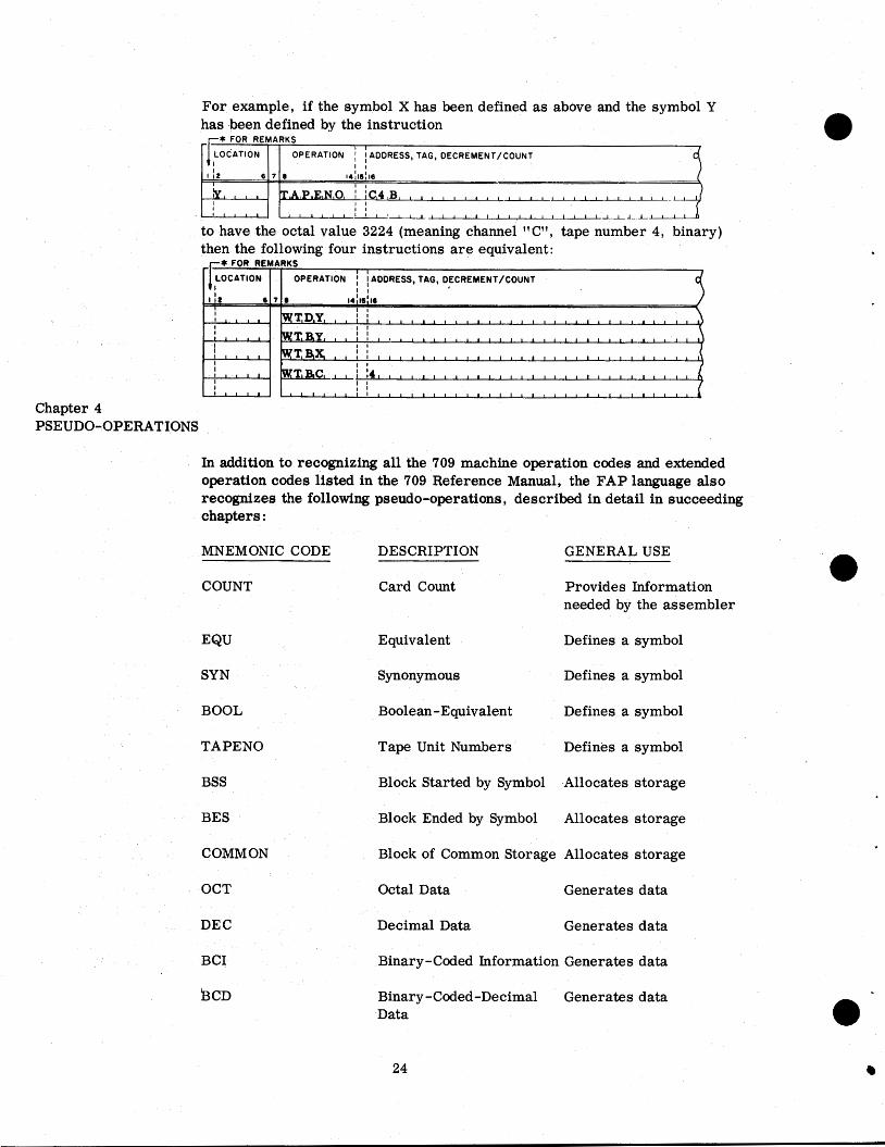
In addition to recognizing all the 709 machine operation codes and extended operation codes listed in the 709 Reference Manual, the FAP language also recognizes the following pseudo-operations, described in detail in succeeding chapters :
For example, if the symbol X has been defined a s above and the symbol Y has been defined by the instruction
* FOR REMARKS
MNEMONIC CODE DESCRIPTION GENERAL USE
COUNT Card Count Provides Information
LOCATION
needed by the assembler
I I OPERATION I ADDRESS, TAG, DECREMENT/COUNT
EQU Equivalent Defines a symbol
SYN
-~[ I I
BOOL
1 1 2 I
TAPENO
BSS
6 7 0
BES
14~15~16 I I
-
I I 1 1 0 1 ,
COMMON
T,A,P,E,N,O, I IC,4 , B , , , , , , , , , , I I I I
' l l ~ I 1 l ' l - l l l I I I I I I I I 1 l L I I I I 1 l l , I , I I
OCT
to have the octal value 3224 (meaning channel "CW , tape number 4, binary) then the following four instructions a re equivalent:
Chapter 4 PSEUDO-OPERATIONS
DEC
BCI
Synonymous Defines a symbol
Boolean-Equivalent Defines a symbol
Tape Unit Numbers Defines a symbol
Block Started by Symbol Allocates storage
Block Ended by Symbol Allocates storage
Block of Common Storage Allocates storage
Octal Data Generates data
Decimal Data Generates data
Binary-Coded Information Generates data
Binary -Coded-Decimal Generates data Data

VFD
ETC
Variable Field-Def inition Generates data
Used only with VFD and CALL
Extend Preceding Instruction
Duplicate Generates data DUP
ENTRY Subroutine Entry Point Communicates with other programs
Communicates with other programs
Call Subroutine CALL
If End of File Communicates with 1/0 subroutine
IFEOF
Directs the assembler to produce non-Monitor absolute binary output or to discontinue vfullw mode of binary output
Absolute Program Follows
ABS
Produces 24 words -per card Binary Output
Used only in absolute programs
FUL
Used only in absolute programs
ORG Program Origin
Used only in absolute programs
Headed Region
Headed Region
Produce Transfer Card
End of This Program
HEAD
Used only in absolute programs
HED
Used only in absolute programs
TCD
Signals end of a symbolic program or subprogram
END
Affects the assembly listing REM
SPACE
EJECT
UNLIST
LIST
Remarks
Generates Blank Lines
Eject to a New Page
Suspend Listing
Affects the assembly listing
Affects the assembly listing
Affects the assembly listing
Affects the assembly listing Resume Listing
Affects the assembly listing Suspend Listing of Generated Data
TITLE
DETAIL Resume listing of Generated Data
Affects the assembly listing

Chapter 5 PSEUDO-OPERATIONS REQUIRED IN EVERY ASSEMBLY
COUNT The FAP assembly program owes some of its speed of assembly to the fact that i t does not keep the computer waiting while a tape rewinds. The intermediate information produced and used during the assembly process
I is written on two tapes, half on each, so that one of these tapes is in use while the other tape is rewinding. In order to know when half of the information has been processed, the assembler must be given an estimate of the number of cards in the symbolic deck. This estimate must be given at the beginning of the symbolic deck.
The COUNT card gives this estimate. This card must be the first card of each symbolic deck. (If there is an ABS card, i t may precede the COUNT card. ) The constituents of the COUNT card are as follows:
1. Blanks in the location field;
2. The operation code COUNT in the operation field; and
3. A single decimal integer, an estimate of the number of cards in the symbolic deck, in the variable field.
The estimated card count is neither a minimum nor a maximum, and if it i t is .grossly inaccurate, the only result will be wasted computer time during the assembly. If the COUNT card is missing, or contains anything but a decimal integer in the variable field, the assembler will assume a card-count of 2000.
END The last card of each symbolic deck must be an END card. When an absolute assembly has been specified by use of the ABS pseudo-operation, the END card has a special use which is described in a later section. In relocatable (that i s , non-absolute) assemblies, the END card consists of the following :
1. Blanks in columns 1-7 ;
2. The operation code END in columns 8-10;
3. Blanks in columns 11-16; and
4. Comment in columns 17 -80. Chapter 6 PREVIOUSLY -DE FINED SYMBOLS
In most cases, it is permissible to refer to a symbol either before or after that symbol is defined. The exceptions to this rule are the pseudo-instructions EQU, SYN, BOOL, BSS, BES, COMMON, DUP, and ORG. A symbol which appears in the variable field of any of these pseudo-instructions must have been defined in a preceding instruction. That is , the symbolic instruction card which defined the symbol must appear nearer the beginning of the symbolic deck than any symbolic instruction card in which the symbol
appears in the variable field of one of the above pseudo-instructions.
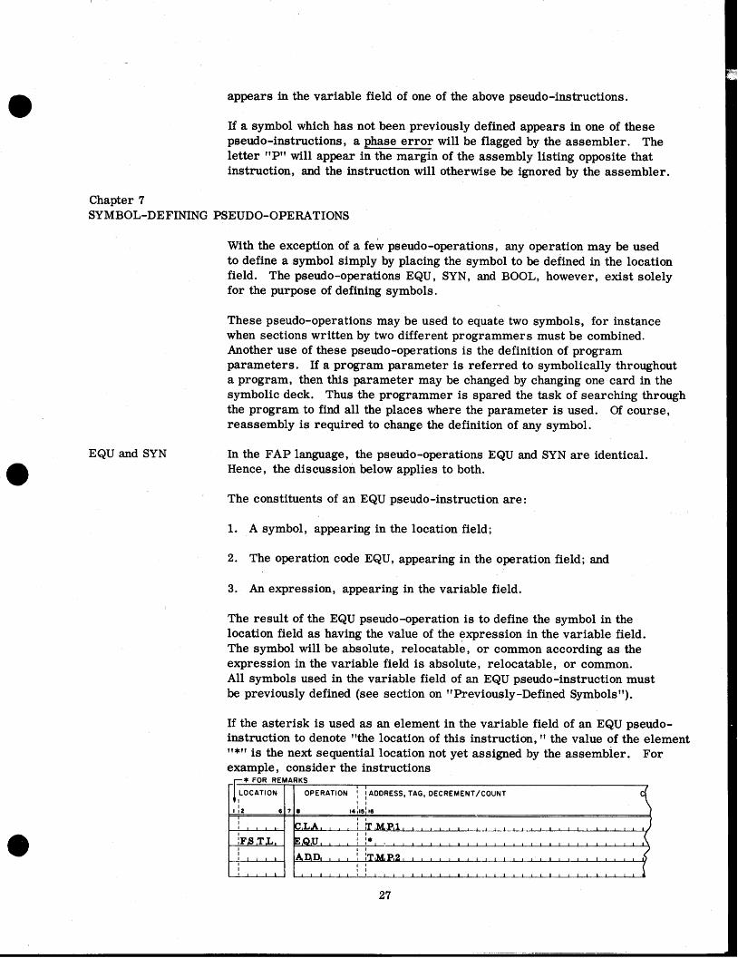
If a symbol which has not been previously defined appears in one of these pseudo-instructions, a phase error will be flagged by the assembler. The letter "PV will appear in the margin of the assembly listing opposite that instruction, and the instruction will otherwise be ignored by the assembler.
Chapter 7 SYMBOL-DEFINING PSEUDO-OPERATIONS
With the exception of a few pseudo-operations , any operation may be used to define a symbol simply by placing the symbol to be defined in the location field. The pseudo-operations EQU, SYN, and BOOL, however, exist solely for the purpose of defining symbols.
These pseudo-operations may be used to equate two symbols, for instance when sections written by two different programmers must be combined. Another use of these pseudo-operations is the definition of program parameters. If a program parameter is referred to symbolically throughout a program, then this parameter may be changed by changing one card in the symbolic deck. Thus the programmer is spared the task of searching through the program to find all the places where the parameter is used. Of course, reassembly i s required to change the definition of any symbol.
EQU and SYN In the FAP language, the pseudo-operations EQU and SYN are identical. Hence, the discussion below applies to both.
The constituents of an EQU pseudo-instruction are :
1. A symbol, appearing in the location field;
2. The operation code EQU, appearing in the operation field; and
3. An expression, appearing in the variable field.
The result of the EQU pseudo-operation is to define the symbol in the location field as having the value of the expression in the variable field. The symbol will be absolute, relocatable, or common according as the expression in the variable field is absolute, relocatable, or common. All symbols used in the variable field of an EQU pseudo-instruction must be previously defined (see section on ttPreviously -Defined Symbolstf).
If the asterisk is used as an element in the variable field of an EQU pseudo- instruction to denote "the location of this instruction, " the value of the element "*" is the next sequential location not yet assigned by the assembler. For example, consider the instructions
* FOR REMARKS
LOCATION I I l
I 12 I I
1 1 1 1 , , I
I F I S I T L o .
I 1 1 .
I I I 1 , I I
6 7 6
OPERATION I I ADDRESS, TAG, DECREMENT/COUNT I I
14115ll6 I I
C I L A I 1 I L I ~ I M P l 1 1 I I 1 I I 1 , I 1 I I I I , 1 I , 1 1 1 I l I I 1 I I
E ~ Q l U t t I t I I * L ~ I I a I I ~ I 1 1 I 1 1 a t 1 1 t 1 1 I i I t I I 1 1 1 I
ADD1 1 1 I I I I T ~ P ~ ~ ~ I ~ ~ I I ~ I I I ~ I I I ~ ~ I ~ ~ ~ I ~ ~ I I ~ I I I I
1 1 1 1 1 1 1 1 1 1 1 1 1 1 1 1 1 I 1 1 l l l l l l l l l l l l l l l l l

BOOL
TAPENO
If the CLA instruction i s assigned to location 00102, the symbol FSTL would be defined as a relocatable symbol (since "*" is always a relocatable element) whose value is 00103, and the ADD instruction would be assigned to location 00103. This example also illustrates the fact that the occurrence of an EQU pseudo-instruction between two instructions does not alter the sequence of locations assigned by the assembler.
In the FAP language, the BOOL pseudo-operation is similar to EQU, except that the defining expression i s evaluated as a Boolean expression (see the section on "Boolean Expressions"). The principal use of the BOOL pseudo- operation is to equate a symbol with an octal number.
The constituents of a BOOL pseudo-instruction are:
1. A symbol, appearing in the location field;
2. The operation code BOOL, appearing-in the operation field; and
3. A Boolean expression, appearing in the variable field.
The result of the BOOL pseudo-operation i s to define the symbol in the location field to be an absolute symbol having the value of the expression in the variable field. No relocatable symbol or common symbol may appear in the variable field of a BOOL pseudo-instruction, or a Boolean e r ror will be signalled by the assembler; in this case the error-flag "B" will appear in the left margin of the assembly listing opposite the BOOL instruction. All symbols used in the variable field of a BOOL pseudo-instruction must be previously defined (see section on ltPreviously-Defined Symbols").
In the FAP language, the TAPENO pseudo-operation is used to equate a symbol with a tape address. Its primary use is in conjunction with the variable-channel tape operations described in a preceding section.
The constituents of the TAPENO pseudo-instruction are:
1. A symbol, appearing in the location field; this symbol may consist of from one to six characters but will usually be a single letter;
2. The operation code TAPENO, appearing in the operation field; and
3. A tape unit designator, appearing in the variable field.
The variable field of the TAPENO pseudo-instruction contains a special type of expression called a "tape unit designator. " This designator consists of a channel letter, followed by a tape-unit number, perhaps followed by the letter "B" to indicate binary mode. The tape unit number may be any number from 1 to 10 inclusive.
The result of the TAPENO pseudo-operation is to define the symbol in the location field to be an absolute symbol whose value is the address of designated tape unit. The address will be that of the designated unit in the BCD mode,

unless the letter l1Bl1 is present following the tape unit number.
To illustrate the TAPENO pseudo-operation, the following examples are given, each preceded by the octal tape address assigned by the assembler:
Tape Address (octal1 1203 1223 2210 3212
Chapter 8 ST ORAG E-ALLOCATING PSEUDO-OPERATIONS
The BSS, BES, and COMMON pseudo-operations are used to reserve blocks of memory for data storage or working space. For example, if a table of 100 cosines is to be read into memory, the instruction
would reserve 100 consecutive locations for the table, and define the symbol TCOS to refer to the first of these locations.
Phase Relocation The variable field of a storage-allocating pseudo-instruction specifies the Errors number of words of storage to be reserved. This number must be fixed
at the time the program is assembled, and may not depend upon how the program is subsequently relocated. (This is not to say that all the words reserved must be used by the program each time; typically the number of words reserved is the maximum number which may be required for a given block of information. ) Hence, the expression in the variable field of a storage -allocating pseudo-instruction must be an absolute expression- an expression whose value i s independent of the relocation process.
If a relocatable or common expression appears in the variable field of a storageallocating pseudo-instruction (BSS, BES, or COMMON), the assembler signals a phase relocation error. The error-flag l1Pl1 is written in the margin of the listing opposite the erroneous instruction, and the instruction i s otherwise ignored.
When an absolute assembly has been specified by the use of the ABS pseudo- operation, all symbols are treated as absolute symbols, and therefore a phase relocation error is impossible.
The BSS (Block Started by Symbol) pseudo-operation is used to reserve an area of memory within a program for data storage or working space.

The constituents of a BSS pseudo -instruction a r e :
1. A symbol o r blanks, appearing in the location field;
2. The operation code BSS, appearing in the operation field; and
3. An absolute expression, appearing in the variable field.
The BSS pseudo-operation performs two functions:
1. If there is a symbol in the location field, this symbol is defined to be a relocatable symbol whose value i s the next location to be assigned by the assembler a t the time the BSS pseudo-operation is encountered.
2. A block of consecutive storage locations is reserved; the number of locations reserved is the value of the expression in the variable field.
Thus, the BSS pseudo-operation reserves a block of storage whose length is given in the variable field, and if there is a symbol in the location field, this symbol refers to the f irst cell of the block. The location of the block within the program i s determined by the location of the BSS card within the program deck.
The BSS pseudo-operation causes an area to be skipped, not cleared. Therefore i t may not be assumed that an area reserved by a BSS pseudo- operation contains zeros. Words of zero may be generated by DEC or OCT in such cases.
(The effect of a BSS on the binary output of the assembler is to cause any binary words in the punch buffer to be written out, and the next output to s tar t at the new card origin. A BSS with a count of zero has no effect on the binary output. )
All symbols appearing in the variable field of a BSS pseudo-operation must be previously defined. The expression in the variable field must be an absolute expression. (See the sections on "Previously -Defined Symbols" md "Phase Relocation Errors . ")
Consider the following example - * FOR REMARKS I I
OPERATION I I ADDRESS, TAG, DECREMENT/COUNT I I
Suppose the symbol ALPHA has been assigned to location 1001. Then the symbol BETA will be assigned to location 1002, and the symbol GAMMA will be assigned to location 1006, leaving four locations (1002, 1003, 1004 and 1005) for the block BETA.

BES The BES (Block Ended by Symbol) pseudo-operation i s used to reserve an area of memory within a program for data storage or working space.
The constituents of the BES pseudo-instruction are:
1. A symbol or blanks, appearing in the location field;
2. The operation code BES, appearing in the operation field; and
3. An absolute expression, appearing in the variable field.
The BES pseudo-operation performs the following two functions:
1. It reserves a block of consecutive storage locations; the number of locations reserved is the value of the expression in the variable field.
2. If there is a symbol in the location field, it defines this symbol to be a relocatable symbol whose value is the - next location to be assigned by the assembler after the block has been reserved.
Thus, the BES pseudo-instruction reserves a block of storage whose length is given in the variable field; if there is a symbol in the location field, this symbol refers to the location after the last location in the block. The location of the block within the program is determined by the location of the BES card within the program deck. If the location field is blank, BSS and BES have the same effect.
The BES pseudo-instruction causes an area to be skipped, not cleared. Therefore i t may not be assumed that an area reserved by a BES pseudo- operation contains zeros. Words of zero may be generated by DEC, or OCT in such cases.
(The effect of a BES on the binary output of the assembler is to cause any binary words in the punch buffer to be written out, and the next output to start with a new card origin. A BES with a count of zero has no effect on the binary output. )
All symbols appearing in the variable field of a BES pseudo-operation must be previously defined. The expression in the variable field must be an absolute expression. (See the sections on Treviously-Defined Symbolsv and "Phase Relocation Errors. ")
Consider the following example * FOR REMARKS
I I OPERATION I I ADDRESS, TAG, DECREMENT /COUNT
I I

COMMON
Suppose the symbol ALPHA has been assigned to location 1001. Then the symbol BETA will be assigned to location 1006, and the symbol GAMMA will also be assigned to location 1006, leaving four locations (1002, 1003, 1004, and 1005) for the block of storage.
In the FAP language, the COMMON pseudo-operation is used to reserve an area of upper memory for data storage or working space. Typically, this pseudo-operation is used when two or more subprograms operate on the same block of information (see the discussion of FORTRAN common usage in part IV).
The constituents of the COMMON pseudo-instruction are:
1. A symbol or blanks, appearing in the location field;
2. The operation code COMMON, appearing in the operation field; and
3. An absolute expression, appearing in the variable field.
The COMMON pseudo-instruction operates in conjunction with a counter, called the common counter in the assembler. This counter keeps track of the location of the next block of common storage to be assigned. Initially the common counter is set to 77461 octal (32561 decimal).
The COMMON pseudo-operation performs the following two functions :
1. If there is a symbol in the location field, it defines this symbol a s a common symbol whose value is the current value of the common counter.
2. It decreases the common counter by the value of the expression in the variable field.
Thus, the COMMON pseudo-operation reserves a block of storage in upper memory. The length of the block is given in the variable field; if there is a symbol in the location field, this symbol is a common symbol which refers to the last location of the block (not the location after the last location as with BES). This usage coincides with the FORTRAN rule that the name of an array refers to the logically-first word of the array, which is stored last in memory.
All symbols appearing in the variable field of a COMMON pseudo-instruction must be previously defined. The expression in the variable field must be an absolute expression. (See the sections on wPreviously-Defined Symbols" and "Phase Relocation, Errors. ") The COMMON pseudo-instruction may not be used in an absolute assembly. If the COMMON pseudo-instruction is used in an absolute assembly, it will be flagged a s an undefined operation; the prefix digit of the octal portion of the listing will be left blank, and the error-flag "0" will appear in the left margin of the listing.
To assure compatibility with future modifications to FAP, all COMMON pseudo-operations should appear together at the end of the program, just

before the END pseudo-operation.
The binary output of the assembler will be preceded by a program card (see page 64). The address portion of the fourth word of the program card will contain the address of the last piece of data assigned downward in common storage, that is, one more than the final contents of the common counter. However, if no COMMON pseudo-instructions occur in the program, this portion of the program card will contain the number zero.
Chapter 9 DATA-GENERATING PSEUDO-OPERATIONS
OCT
The FAP language provides five pseudo-operations (OCT, DEC, BCI, BCD, and VFD) which may be used to introduce words of data into a program during assembly. Numbers introduced in this way are often referred to a s %onstants. l1
A sixth pseudo-operation, DUP, causes a sequence of symbolic instructions to be duplicated a specified number of times. DUP is often used in conjunction with VFD to generate tables of data.
The OCT (Octal Data) pseudo-operation is used to introduce, into a program, binary data expressed in octal form. The constituents of the OCT pseudo- instruction are :
1. A symbol or blanks, appearing in the location field;
2. The operation code OCT, appearing in the operation field; and
3. One or more subfields, each containing a signed or unsigned octal integer, appearing in the variable field.
The subfields of the variable field are separated by commas; the number of subfields permissible is limited only by the restrictions that the last subfield must be terminated by a blank, and that the entire instruction must fit on one symbolic card. Of course, several OCT instructions may appear in succession.
The OCT pseudo-operation performs the following two functions:
1. If there i s a symbol in the location field, this symbol is defined to be a relocatable symbol whose value is the next location to be assigned by the assembler when the OCT instruction is encountered.
2. Each subfield of the variable field is converted to a binary word; these words are assigned to successively higher storage locations as the variable field is processed from left to right.
Thus, the OCT pseudo-instruction'introduces data words into consecutive memory locations, and if there is a symbol in the location field, this symbol refers to the first of these locations. Consecutive commas in the variable field cause the number zero to be generated, a s does a comma followed by a blank. Hence the number of words of data generated is always one more than the number of commas in the variable field.
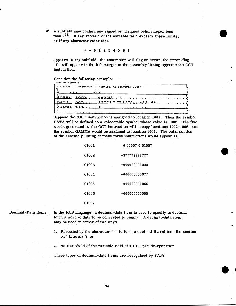
A subfield may contain any signed or unsigned octal integer less than 236. If any subfield of the variable field exceeds these limits, or if any character other than
appears in any subfield, the assembler will flag an error ; the error-flag "Eft will appear in the left margin of the assembly listing opposite the OCT instruction.
Consider the following exam~le : V * FOR REMARKS
I I OPERATION I I ADDRESS, TAG, DECREMENT/COUNT
Suppose the IOCD instruction is assigned to location 1001. Then the symbol DATA will be defined as a relocatable symbol whose value is 1002. The five words generated by the OCT instruction will occupy locations 1002-1006, and the symbol GAMMA would be assigned to location 1007. The octal portion of the assembly listing of these three instructions would appear as:
Decimal-Data Items In the FAP language, a decimal-data item is used to specify in decimal form a word of data to be converted to binary. A decimal-data item may be used in either of two ways:
1. Preceded by the character 'l=" to form a decimal literal (see the section on l'Literalsl'); or
2. As a subfield of the variable field of a DEC pseudo-operation.
Three types of decimal-data items are recognized by FAP:
1. Decimal integer. A decimal integer is composed of a string of digits, possibly preceded by a plus or minus sign. A decimal integer is distinguished from other types of decimal-data items by the fact that the letter B, the letter E, and the decimal point are all absent.
2. Floating point number. A floating point number has two components: - - a) The principal part, which is a decimal number written with a decimal
point. The decimal point may appear at the beginning or end of the principal part, or within the principal part, or may be omitted if the exponent part is present. If the decimal point is omitted, it is assumed to be located at the right-hand end of the principal part.
b) The exponent part, which consists of the letter "E" followed by a signed or unsigned decimal integer. The exponent part must follow the principal part; it may be omitted i f the principal part contains a decimal point.
A floating point number is distinguished from a decimal integer by the fact that either a decimal point, or the letter "E", (or both) is present. It is distinguished from a fixed-point number by the fact that the letter l'B1l is absent.
3. Fixed point number. A fixed point number has three components: a) The principal part, which i s a decimal number written with or
without a decimal point. The decimal point may appear at the beginning or end of the principal part, or within the principal part, or may be omitted. If the decimal point is omitted, it is assumed to be located at the right-hand end of the principal part.
b) The exponent part, which consists of the letter "Eft followed by a signed or unsigned decimal integer. The exponent part may be absent; if present, it must follow the principal part, and may precede or follow the binary-place part.
C) The binary-place part, which consists of the letter "Bfl followed by a signed or unsigned decimal integer. The binary-place part must be present in a fixed point number, and must follow the principal part. If the number has an exponent part, the binary-place part may precede or follow the exponent part. A fixed point number is distinguished from other types of decimal- data items by the presence of the letter "BW.
A decimal integer may represent any positive or negative binary number whose magnitude is less than 235. For example the decimal integer
would be converted to the thirty-six bit number whose octal representation is

A floating point number will be converted to a normalized floating point binary word in the standard 709 floating point binary format (see the 709 Reference Manual). The exponent part, if present, specifies a power of ten by which the principal part will be multiplied during conversion. For example, all of the following floating point numbers a re equivalent and will be converted to the same floating point binary number:
A fixed point number is converted to a fixed point binary number which contains an understood binary point. The purpose of the binary-place part of the number is to specify the location of this understood binary point within the word. The number which follows the letter "B" specifies the number of binary places in the word to the left of the binary point (that i s , the number of integral places in the word). The sign bit is not counted. Thus the binary-place part "OTt specifies a 35-bit binary fraction. ?'B2" specifies two integral places and 33 fractional places. "B35" specifies a binary integer. "B-2" would specify a binary point located two places to the left of the leftmost bit of the word, that is , the word would contain the low-order 35 bits of a 37-bit binary fraction. As with floating point numbers, the exponent part (if present) specifies a power of ten by which the principal part will be multiplied during conversion.
In the process of shifting the converted word to position the binary point, significant bits may be shifted past the right-hand end of the word and lost; no e r ror will be indicated. However, if non-zero bits must be shifted past the left-hand end of the word, an error will be indicated by the assembler. Thus, the integral part of a fixed point number must be small enough to fit in the number of integral places allowed. Also, if the binary-place part is negative, the number must be an appropriately small fraction.
For example, the following fixed point numbers all specify the same configuration of bits; but not all of them specify the same location for the understood binary point:

DEC
All of these fixed point numbers will be converted to the binary configuration whose octal representation is
The DEC (Decimal Data) pseudo operation is used to introduce, into a program, words of data expressed as decimal numbers. DEC is identical with OCT, except that the subfields of the variable field are taken to be decimal-data items (see preceding section).
The constituents of the DE C pseudo-instruction a re :
1. A symbol or blanks appearing in the location field.
2. The operation code DE C, appearing in the operation field; and
3. One or more subfield, each containing a decimal-data item (see above), appearing in the variable field.
The subfields of the variable field are separated by commas; the number of subfields permissible is limited only by the restrictions that the last subfield must be terminated by a blank, and that the entire instruction must fit on one symbolic card. Of course, several DEC instructions may appear in succession.
The DEC pseudo-instruction performs the following two functions:
1. If there i s a symbol in the location field, this symbol is defined to be a relocatable symbol whose value is the next location to be assigned by the assembler when the DE C pseudo-operation i s encountered.
2. Each subfield of the variable field is converted to a binary word; these words are assigned to successively higher storage locations as the variable field is processed from left to right.
Thus, the DEC pseudo-instruction introduces data words into consecutive memory locations, and if there is a symbol in the location field, this symbol refers to the first of these locations. Consecutive commas in the variable field cause the number zero to be generated, as does a comma followed by a blank. Hence the number of words of data generated is always one more than the number of commas in the variable field.
If the variable field of a DEC instruction contains anything other than valid decimal -data items (see the preceding section) the assembler will flag an error ; the error -flag 'lEl1 will appear in the left margin of the assembly listing opposite the DE C instruction.
Consider the following example

* FOR REMARKS I I
OPERATION I I ADDRESS, TAG, DECREMENT/COuNT I I
Suppose the IOCD instruction is assigned to location 1001. Then the symbol DATA will be defined to be a relocatable symbol whose value is 1002. The five words generated by the DEC instruction will occupy locations 1002-1006 and the symbol GAMMA will be assigned to location 1007. The octal portion of the assembly listing of these three instructions would look like this:
01007
BCI In the FAP language, the BCI (Binary Coded Information) pseudo-operation is used to introduce, into a program, binary-coded character data. Each data word generated by this pseudo-operation consists of six 6-bit characters in the standard 709 character code (see the section on "BCD Character CodeM in this manual). The constituents of the BCI pseudo-operation are:
A symbol or blank, appearing in the location field.
The operation code BCI, appearing in the operation field.
Two subfields appearing in the variable field: a) The count subfield, which consists of a single digit, followed by
a comma (a comma in column 12 specifies a count of ten, see below).
b) The data subfield, whose length is determined by the count subfield.
The number in the count subfield specifies the number of six-character 709 words to be generated; the number of characters in the data subfield is the number in the count subfield multiplied by six. Since the count subfield determines the total length of the variable field, the comments field is taken to commence immediately following the end of the data subfield, and no blank character is needed to separate the comments field

from the variable field.
The data subfield may contain any combination of valid 709 characters including comma and blank. Thus the BCI pseudo-operation i s an exception to the rule that the variable field is terminated by a blank.
The BCI pseudo-operation performs the following two functions :
1. If there is a symbol in the location field, this symbol is defined to be a relocatable symbol whose value is the next location to be assigned by the assembler when the BCI pseudo-operation is encountered.
2. The first six characters of the data subfield are converted to 709 character code (see the section on lfBCD Character Codeff in this manual); the resulting binary word is assigned to the next storage location to be assigned by the assembler. If the number in the count subfield is greater than one, the next six characters are converted and assigned to the next storage location, and so on until the number of words specified by the count subfield have been generated.
Thus, the BCI pseudo-instruction introduces data words into consecutive memory locations, the number of words generated being equal to the number In the count subfield. If there is a symbol in the location field, i t refers to the first word of data generated.
If columns 8-12 of the symbolic card contain, respectively the characters
B C I blank comma
then the contents of columns 13-72 will be used to generate ten words of data.
Consider the following example : * FOR REMARKS I I
OPERAT ION I ADDRESS, TAG, DECREMENT/COUNT
Suppose the IOCD is assigned to location 1001. Then the symbol DATA will be defined as a relocatable symbol whose value is 1002. The two words generated by the BCI instruction will occupy locations 1002 and 1003, and the symbol GAMMA will be assigned to location 1004. The octal portion of the assembly listing of these three instructions would look like this:

BCD The BCD pseudo-operation is a 704-SAP pseudo-operation which has been included in the FAP language to simplify changing 704 symbolic programs into 709 programs. This pseudo-operation has been supplanted by BCI in FAP. The BCD pseudo-instruction is exactly like BCI, with the following exceptions :
1. The operation code BCD appears in the operation field.
2. The count digit must appear in column 12.
3. No comma separates the count digit from the data subfield; the data subfield always begins in column 13.
4. A blank or zero in column 12 is used to indicate ten words of data.
VFD The VFD (Variable Field-Definition) pseudo-operation is used primarily for the generation of tables for use with the 709 l'convertll operations. The constituents of the VFD pseudo-instruction are:
1. A symbol or blank, in the location field;
2. The operation code VFD, in the operation field; and
3. One or more subfields (described below), in the variable field.
In the FAP language, each VFD instruction generates one or more binary words of data. Each subfield of the variable field generates one or more bits of this data. Thus the unit of information for this pseudo-operation is the single bit. Each subfield is of one of three types:
Symbolic
Octal (or Boolean)
Hollerith
The constituents of a subfield are:
1. The bit count; An unsigned decimal integer which specifies how many bits of the data word will be generated by this subfield.
2. The type-letter ; I
The letter "0" signifies that the subfield is octal(Boo1ean). The letter "H" signifies that the subfield is Hollerith. The absence of a type- letter signifies that the subfield is symbolic.
3. The separation-character "/"(slash). 4. The data item.

The form of the data item depends on the type of subfield:
1. In a symbolic subfield, the data consists of one expression.
2. In an octal (Boolean) subfield, the data item consists of one octal integer or one Boolean expression.
3. In a Hollerith subfield the data consists of a string of characters, none of which is comma or blank.
The subfields a re separated by commas. Any number of subfields may be used, but the lengt,h of each subfield must be sixty -three bits or less.
The VFD pseudo-operation performs the following two functions:
1. If there is a symbol in the location field, this symbol is defined to be a relocatable symbol whose value i s the next location to be assigned by the assembler when the VFD instruction is encountered.
2. Successive subfields of the variable field are converted and packed to the left to form generated data words. If n is the bit count of the f irst subfield, then the data item in that subfield is converted to an n-bit binary number. This n-bit binary number is placed in the leftmost n bit-positions of the f irst data word to be generated; the sign position is here regarded as the first bit-position. If n exceeds 36, the leftmost 36 bits of the converted data item form the first generated data word, and the remaining bits a re placed in the first n-minus-36 bit-positions of the second generated data word. Each succeeding subfield is converted and placed in the leftmost bit-positions remaining after the preceding subfield has been processed. The data words generated in this way a re assigned to successively higher storage locations. If the total number of bit-positions used is not a multiple of 36, then the unused bit-positions a t the right of the last generated data word will be filled out with zeros.
The data item in a symbolic subfield is converted as a symbolic expression (see the section on "Symbolic Expressions"). Let n be the bit count of the subfield. If the data item a s converted occupies more than n bits, only the rightmost n bits of the converted data item a r e used. If the data item, a s converted, occupies fewer than n bits, sufficient zero bits a re placed at the left of the converted data item to form an n-bit binary number. Neither condition is regarded a s an e r r o r by the assembler. If the data item is a relocatable expression or a common expression (see the section on "Types of Expressions"), then the subfield must be s o situated in relation to preceding fields that its rightmost bit coincides with the rightmost bit of a generated data word, o r with the rightmost bit of the decrement portion of a generated data word. A violation of this rule will be flagged a s a relocation e r r o r by the assembler.
The data item in an octal subfield may be an unsigned octal integer of any length. If the bit count of the subfield is 36 or less, the data item

may be any valid Boolean expression (see the section on "Boolean Expressions~) . Note that an unsigned octal integer is one type of valid Boolean expression. If the bit count of the subfield exceeds 36, then the data item must be an unsigned octal integer. Let n be the bit count of the subfield. If the data item, as converted, occupies more than n bits, only the rightmost n bits of the converted data item are used. If the data item, as converted, occupies fewer than n bits, sufficient zero bits are placed at the left of the converted data item to form an n-bit binary number. Neither condition is regarded as an error by the assembler.
The data item in a Hollerith subfield may consist of any combination of characters other than comma or blank. Each character is converted to its six-bit binary-code equivalent. Let n be the bit count of the subfield. If the data item, as converted, occupies more than n bits, only the right- most n bits are used. If the data item, as converted, occupies fewer than n bits, sufficient six-bit groups of the form 110000 (the BCD code for blank) are placed at the left of the converted data item to form an n-bit binary number; if n is not a multiple of six, the appropriate right hand portion of this group will appear at the extreme left of the n-bit result. In other words, the data item is converted as if the leftmost character were preceded by an unlimited number of blanks. If the bit count of the subfield is not a multiple of six, the leftmost character used, or leftmost blank used, is truncated. None of the conditions discussed in this paragraph is regarded as an error by the assembler.
The bit c m t of each subfield must be 63 or less. If the bit count of a subfield exceeds 63, it will be taken as 63 and the assembler will signal an error by placing the letter "E" in the margin of the listing.
The pseudo-operation ETC, described below, may be used to extend the variable field of a VFD instruction. Any number of ETC instructions may follow a VFD to give an effective variable field of unlimited length. If there is a symbol in the location field of the VFD instruction, this symbol refers to the first generated data word.
The asterisk may be used as an element in the variable field of a VFD instruction. When so used, the value of this element is the next location to be assigned by the assembler when the subfield containing the asterisk .
is about to be processed. That is, the value of the asterisk will be the location assigned to the generated data word which contains the leftmost bit of the subfield in which the asterisk appears. Failure to keep this &act in mind may lead to confusion, since the bits generated by one subfield may occupy as many as three different generated data words.
As an example, suppose the programmer would like to break up a single 36-bit word into four parts as follows:
1. Positions S, 1-9 : the binary equivalent of the decimal integer 895.
2. Positions 10-14: the binary equivalent of the octal integer 37

ETC
8. Positions 15-20: the binary code for the character "C"
4. Positions 21-35: the (binary) value of the symbol ALPHA
Then he may write: * FOR REMARKS
I I OPERATION I I ADDRESS, TAG, DECREMENT/COUNT
I I
Consider also the following example : * FOR REMARKS
I I OPERATION I I ADDRESS, TAG, DECREMENT/COUNT
I I
Suppose the IOCD instruction is assigned to location 1001. Then the symbol DATA will be defined to be a relocatable symbol whose value is 1002. Five data words will be generated by the VFD and ETC instructions, and these will occupy locations 1002-1006. The symbol GAMMA will refer to location 1007. The octal portion of the assembly listing of these five instructions would look like this :
01003 223606024000
01004 000000001001
01005 000000000000
01006 001005000000
01007
In the FAP language, the ETC pseudo-operation i s used to extend the variable fields of VFD and CALL instructions. The constituents of the ET C pseudo-instruction are :
1. Blanks, appearing in the location field;
2. The operation code ETC in the operation field; and
3. One or more subfields, appearing in the variable field.

An ETC instruction may appear only in one of three positions in the symbolic deck.
1. Immediately following a VFD instruction;
2. Immediately following a CALL instruction; or
3. Immediately following another ET C instruction.
An additional restriction is that an ET C instruction may not appear immediately after the last instructian in the range of a DUP (see the section on the DUP pseudo-operation).
The variable field of the instruction preceding an ETC pseudo-operation must contain a number of complete subfields, and must be terminated by a comma followed by a blank. That i s , if the variable field of a VFD or CALL instruction is divided among several symbolic cards, the divisions must take place between subfields, and the separating comma at the point of division goes with the subfield which precedes it.
If a VFD, CALL, or ETC instruction is followed by an ETC instruction, but does not have a comma immediately preceding the blank which terminates its variable field, then that instruction will be assembled a s if the comma had been present, but the assembler will flag an error by placing the letter "EM in the left margin of the assembly listing. If a symbol appears in the location field of an ET C pseudo-operation, the symbol will be ignored, and the error-flag "EV will be placed in the left margin of the assembly listing. If an ETC occurs immediately following the last instruction in the range of a DUP, or immediately following any instruction except a VFD, a CALL, or a valid ETC instruction, then the assembler will fail to recognize the
, operation code and will place the error-flag 1'0" in the margin of the assembly listing.
Each subfield of the variable field of an ETC instruction will be processed in the same way a s subfields of the immediately-preceding VFD, CALL, or ETC instruction. Thus for example, the first instruction below is equivalent to the set of three instructions which follow it:
DUP The DUP (duplicate) pseudo-operation causes an instruction or sequence of instructions to be duplicated. Its primary use is in the generation of tables. The constituents of the DUP pseudo-instruction are :
*

A symbol or blanks, appearing in the location field;
The operation code DUP, appearing in the operation field; and
Two subfields: the instruction count and the iteration count, in that order, in the variable field. Each subfield contains one symbolic expression.
The DUP pseudo-operation performs the following functions:
1. If there is a symbol in the location field, this symbol is defined to be a relocatable symbol whose value is the next location to be assigned by the assembler.
2. The instruction count and iteration count subfields are evaluated (see the section on "Evaluation of Expressions").
3. Duplication is performed as described below, under control of the instruction count and iteration count.
All symbols which appear in the variable field of a DUP instruction must be previously defined (see the section on vPreviously-Defined Symbolsv).
Let the letter m stand for the instruction count and the letter n for iteration count. Then the meaning of the DUP instruction is "Duplicate the next m instructions n times. The set of m instructions immediately following the DUP instruction is called the range of the DUP. The effect of the DUP'pseudo-operation is as if the set of m symbolic cards making up the range of the DUP was copied n-1 times (except for the location fields), and these n-1 copies placed in the symbolic deck behind the original set. (except that certain pseudo-operations may not be duplicated).
The duplication process consists of n iterations. During the first iteration, the instructions in the range of the DUP are assembled normally, just as if the DUP had not occurred. Symbols which are defined within the range of the DUP are defined during the first iteration. Each subsequent iteration is performed by assembling all of the instructions of the range in order, but without defining any symbols. The number of binary words generated by the duplication process is n times the number of words generated by the instructions in the range of the DUP.
Any FAP operation or pseudo-operation may be used in the range of a DUP except the pseudo-operations :
ORG
DUP
COMMON
ENTRY

COUNT
ABS
END
The pseudo-operations BSS and BES may be used in the range of the DUP provided the length of the block of storage reserve remains the same for all iterations of the DUP (see the discussion of the asterisk, which follows).
The asterisk may be used as an dement within the range of a DUP, in which case the value of this element differs during different iterations of the DUP. This provides a very powerful method for generating tables.
* FOR REMARKS 1 I
OPERATION I I ADDRESS, TAG, DECREMENT/COUNT I I
which is equivalent to ,[* FOR REMARKS
LOCATION OPERATION ' i ADDRESS, TAG, DECREMENTICOUNT COMMENTS
In the FAP language, the ENTRY and CALL pseudo-operations are used within a program to provide communication links between that program and other programs. ' The character "$I1 may also be used for this purpose. The descriptions which follow assume that the reader i s familiar with the use of the program card and transfer vector in FORTRAN; a thorough discussion of these and related subjects appears in Part I11 of this manual.
ENTRY In the FAP language, the ENTRY pseudo-operation is used to identify certain locations within the program as sub-routine entry points. A main program is distinguished by the fact that it contains no ENTRY instructions.

The constituents of the ENTRY pseudo-instruction are:
1. Blanks appearing in the location field;
2. The operation code ENTRY, appearing in the operation field; and
3. A single symbol, appearing in the variable field.
The symbol in the variable field must be defined subsequently as a relocatable symbol.
The ENTRY pseudo-operation performs the following two functions:
1. The symbol in the variable field (followed by sufficient blanks to make six characters) is placed in the program card.
2. The value of the symbol, as defined in the program, is placed in the program card following the symbol itself.
Thus the ENTRY pseudo-instruction establishes the symbol as a name of the program, and identifies with i t the associated entry point.
For example, the library subroutine to compute sines and cosines begins as follows :
As many ENTRY pseudo-instructions as desired may be used in a program. All ENTRY cards must appear together in the symbolic deck, following the COUNT card and the page-title card (see above), and preceding all other symbolic cards. The only exception to this rule is that any number of cards with the character "*" in column 1 ("remarks" cards) may appear before or among the ENTRY cards.
The ENTRY pseudo-operation may not be used in an absolute assembly. If ENTRY is used'in an absolute assembly, it will be flagged as an undefined operation; the prefix digit of the octal portion of the listing will be left blank, and the error flag "0" will appear in the left margin of the listing.
The ENTRY pseudo-instruction may also be used to provide secondary entries for library subroutines. If the symbol in the variable field of the ENTRY instruction is preceded by a minus sign, the word on the program card which contains the address of this entry point will have a

CALL
a relocatable symbol whose value is the next location to be assigned by the assembler when the call instruction is encountered.
1 in the sign position. This will cause the BSS Loader to ignore the subroutine unless one of its primary entries has also been called. This feature of FAP is useful only when assembling subroutines for inclusion in the library tape.
In the FAP language, the CALL pseudo-operation is used to produce a subroutine calling sequence of the type generated by the CALL statement in FORTRAN (see Part I11 of this manual). The constituents of the CALL pseudo-instruction are :
1. A symbol or blanks, appearing in the location field;
2. The operation code CALL, appearing in the operation field; and
3. One or more subfields, appearing in the variable field; a) The first subfield of the variable field must contain a single symbol
(the name of a subroutine). b) Each subsequent subfield (if any) may contain any symbolic expression.
The subfields are separated by commas; the number of subfields permissible is unlimited, since the ETC pseudo-operation may be used to extend the variable field to any desired length.
The CALL pseudo-operation performs the following functions :
1. If there is a symbol in the location field, this symbol is defined to be
2. The first subfield of the variable field contains the name of the subroutine called
. a) If this name is not already present in the transfer vector, it is placed there (followed by sufficient blanks to make six characters), and the name is defined to be a relocatable symbol whose value is the corresponding location in the transfer vector.
b) A TSX instrmction, having a tag of 4 and as its address the transfer- vector location containing the subroutine name, is assembled and assigned to the next location to be assigned by the assembler.
3. Each subsequent subfield of the variable field contains a parameter, and is assembled as the address of a TSX instruction whose tag is zero. These tagless TSX instructions are assigned to successively higher locations.
Thus the CALL pseudo-operation enters a name in the transfer vector (unless the name is already in the transfer symbol in the location field) this symbol refers to the first instruction of the calling sequence.
Caution must be observed when using constants in a calling sequence to a FORTRAN subprogram. A FORTRAN subprogram always regards a calling-sequence parameter as the address of the location where the operand is stored, Thus if it is necessary to communicate the number V 1 to a

FORTRAN subprogram as an integer, the parameter in the CALL instruction must be a symbol assigned to a cell whose decrement contains the number "3". Note that certain FAP-coded subprograms, notably DUMP, are written to accept either the operand or its address in the calling sequence.
The CALL pseudo-operation may not be used in an absolute assembly. If the CALL pseudo-operation is used in an absolute assembly, it will be flagged as an undefined operation; the prefix digit of the octal portion of the listing will be left blank, and the error flag "0" will appear in the left margin of the listing.
Note: A symbol which has been defined a s a subroutine name may not be used in the variable field of any pseudo-operation except CALL.
Standard Error Following the procedure adopted in 709 FORTRAN, the standard error Procedure Option procedure has been made available in FAP programs through the Editor
Deck on an optional basis. An installation desiring to utilize the standard error detection procedure may do this by removing cards from the Editor Deck, while any installation not wanting the facility may leave the Editor Deck intact to omit the additional assembled instructions.
In order to make the standard error detection procedure operative for the 709 FORTRAN compiler, one or more cards must be removed from the Editor Deck; the procedure to follow is described in FORTRAN literature accompanying the Editor Deck. In addition, in order to make the standard error detection procedure operative with the FAP assembler, the card labeled 9F04FLOW must also be removed from the Editor Deck.
The removal of this card from the Editor Deck will add two words to the beginning of each subprogram assembled by FAP, and will also affect the assembly of calling sequences produced by the CALL pseudo-operation. Words will not be added to the beginning of FAP main programs, but calling sequences produced by the CALL pseudo-operation will be lengthened as in subprograms. Subroutine references made by use of the "$" will not be affected.
The purpose of the standard error detection feature is to provide information which will enable an error-tracing routine to tabulate the sequence of subroutine-calls which led to a given error. When used with a FORTRAN program, the error-tracing routine will give the name of the subprogram in which the error occurred, the name of the higher-level subprogram which called it, the external and internal formula numbers of the FORTRAN statement which called the error -producing subprogram, the name of the still-higher-level subprogram which called the higher-level subprogram, and so on back to a statement in the main program. The standard error detection feature in FAP will make it possible for the error-tracing routine to give similar information about FAP-assembled programs, and to continue tracing through FAP and FORTRAN programs. Instead of providing the error-tracing routine with external and internal formula numbers, the standard error detection feature in FAP gives the octal location of the calling sequence involved.

The standard error detection feature will add two binary words to the beginning of each assembled subprogram. These two words will be introduced immediately following the last word of the transfer vector, or at the very beginning if the subprogram has no transfer vector. The first of these words is called the linkage director, because the information i t contains when an error occurs will enable the error-tracing routine to find the statement which called the subprogram. Initially the linkage director will contain the number zero. The subprogram should store index register 4 in the decrement of the linkage director every time the subprogram is entered. Note that FAP does not automatically produce the necessary SXD instructionsw If the first location of the program proper is assigned a location symbol, then the address of the linkage director may be obtained by subtractiag 2 from this symbol.
Immediately following the linkage director in each subprogram, the standard error detection feature will introduce a word containing the BCD name of the subprogram, which is the name given in the variable field of the first entry instruction. The error-tracing routine will refer to this location to find the name of the subprogram. A symbolic subprogram using the standard error detection feature might begin as follows:
* FOR REMARKS ~FOCATION I I OPERATION / I ADDRESS, TAG. DECREMENTICOUNT COMMENTS I I
In this case the linkage director would occupy COS-2, and COS-1 would ' contain the number 623145606060, which is the BCD equivalent of SIN.
The standard error detection feature will lengthen each calling sequence produced by the CALL pseudo-instruction by introducing two instructions at the end of the calling sequence:
* FOR REMARKS I I
OPERATION ' I ADDRESS, TAG, DECREMENT/COUNT ! !
where A and B together give the octal location, relative to the beginning of the program, of the first word of the calling sequence, C gives the location of the linkage director in a subprogram. In a main program C is zero. If the location of the first word of the calling sequence is less than 327708, relative to the beginning of the program, then A will be zero, and B will be a binary number which when converted to decimal will give the correct octal location. Otherwise A will contain the high-order
Subroutine Reference Using 1 1 $ 1 1
octal digit of the location, and B, when converted to decimal, will give the low-order four octal digits.
If the first subfield of the variable field of an instruction consists of the character 1 1 $ 1 1 followed by a single symbol, the assembler will do the following:
1. If the symbol is not already present in the transfer vector, the symbol is placed in the transfer vector (followed by sufficient blanks to make six characters), and the symbol is defined to be a relocatable symbol whose value is the corresponding location in the transfer vector.
2. The instruction is assembled in the normal manner, as if the character " $ 1 1 were not present.
Thus, in the FAP language, preceding a symbol with the character 11$11
has the effect of identifying that symbol as the name of a subroutine. Since a symbol need be so identified only once in a program, the use of the 1 1 $ 1 1 is necessary only when the subroutine name does not appear a s the first subfield of the variable field of a CALL instruction, and then it is necessary to prefix the character 1 1 $ 1 1 to just one occurrence of the subroutine name. No harm is done, however, if the 1 1 $ 1 1 is used more than once with the same symbol.
The use of the 1 1 $ 1 1 for subroutine reference is subject to the following restrictions :
1. In an absolute assembly, the character 1 1 $ 1 1 may not be used as described here, since it is used in conjunction with the heading feature. (The heading feature is available in FAP only in absolute assemblies. ) i'he discussion in this section does not apply to absolute assemblies.
The character 11$" may not be used in the variable field of a pseudo- instruction. In fact, no symbol which has been defined as the name of a subroutine (either by use of the " $ 1 1 or by a CALL pseudo-operation) may be used in the variable field of any pseudo-operation except CALL. If the character 11$11 is used in the variable field of a pseudo-instruction it will be ignored. If a symbol which has been defined as a subroutine name appears in the variable field of a symbol-defining or storage- allocating pseudo-instruction, the instruction will be flagged as a phase error.
3. When the character l t $ l l is used to identify a subroutine name, this character must be the first character of the variable field. That is , the character l f $ " may be used only in the address subfield of an instruction. Expressions involving the subroutine name, but not including the character 1 1 $ 1 1 , may be used in the address, tag, or decrement subfield of an instruction, if the subroutine name is established in the transfer vector by its appearance elsewhere in the program (as the first subfield of the variable field of a CALL pseudo-operation, or, preceded by a l l $ l f , as an address of a machine operation).

4. In order to assure compatibility with future modifications to FAP, any symbol preceded by the character "$" should consist of five or fewer characters.
For example,
is equivalent to * FOR REMARKS
COMMENTS I I
I L - I I , I ' I I I . I 1 l . t 1 I I I 1 I I I t ~ I I I I I I I I I 1 1 l I I I I l t ~ I
unless the standard error procedure is used; see above.
As a second example, suppose several tables have been assembled as subroutines, to avoid having to reassemble the tables each time the program is reassembled. The "table" subroutine might begin:
and so on.

IFEOF
The program which utilized these tables might contain the following sequence of instructions (see the programming examples in the 709 Manual) :
The IFEOF pseudo-operation is used to communicate with a library subroutine which is not in use at the time of writing of this bulletin. Its operation is described here for the sake of completeness; its use will be discussed in the write-up of the subroutine.
The instruction * FOR REMARKS
I I OPERATION I I ADDRESS, TAG, DECREMENT/COUNT
I I
causes two binary instructions to be generated just as if the programmer had written: 1;;
I. --LL
Chapter 11 ABSOLUTE ASSEMBLIES
ABS
ARKS
OPERATION / ADDRESS, TAG, DECREMENT/COUNT I I
In addition to assembling programs for use within the Monitor system, the FAP assembler will also assemble absolute programs. The deck of binary cards produced by an absolute FAP assembly may be loaded and executed without the use of the Monitor system; in fact, an absolute binary deck cannot be used within the Monitor system.
In the FAP language, the ABS pseudo-operation is used to specify an absolute assembly, and, within an absolute assembly, to discontinue the llfull" mode of binary output. The ABS card is punched as follows:
1. Blanks in columns 1-7.
2. The operation code ABS
3. Blanks in columns 11-72.
To obtain an absolute assembly, either a FUL card o r an ABS card must appear at the beginning of the symbolic deck; only the COUNT card, the page-title card, and listing or binary output control pseudo- operation cards may precede this card. It is always permissible

for this card to be the first card of the symbolic deck (but following the Monitor control cards; which are not regarded as being part of the symbolic deck).
In an absolute assembly :
The following pseudo-operations may not be used ( and will be regarded as undefined operations):
COMMON
ENTRY
CALL
IFEOF
The following pseudo-operations, not otherwise permissible, may be used:
ORG
HEAD
HED
FUL
ABS
The END pseudo-operation is used differently; see the description below.
The character "$" may not be used for subroutine reference, but may be used for heading reference; see the description of the HEAD pseudo-operation.
All symbols (and hence all expressions) are taken as absolute symbols. Hence, relocation errors and phase relocation errors are impossible.
Binary output format uiill depend on the Monitor-control cards used. If no on-line punching has been specified, standard 23-instructions- per-card 709 column-binary card images, or fffullv column-binary card images, will be produced on the off-line punch tape. If on-line punching of column-binary cards has been specified, standard 23- instructions -per -card 709 column-binary cards, or fffullw column- binary cards, will be punched. If on-line punching of row-binary cards has been specified, standard 22-instructions -per-card 704 row- binary cards, or fffulllf row-binary cards, will be punched. (See

Chapter 13 for a description of these card formats. )
FUL
ORG
7. Binary output will be produced even if errors are detected by the assembler.
The ABSpseudo-operation may be used within an absolute assembly to cause discontinuance of the VulP mode of binary output. (See Chapter 13. ) When so used, the ABS card will appear somewhere after the appearance of a FUL card. Its effect on the binary output is to cause any words in the punch buffer to be written out, and the next output to start on a new card in the appropriate absolute mode of punching. The next location assigned by the assembler becomes the new card origin. If an ABS card is encountered in an absolute assembly when the %W1 mode is not in force, it has no effect whatever.
In a relocatable assembly (that is, one in which no FUL or ABS card appeared initially), any appearance of ABS will be treated as an undefined operation.
In the FAP language, the FUL pseudo-operation is used to specify binary output in the 24-words -per -card lffullw mode. (See Chapter 13 for a description of this mode. ) The FUL card is punched as follows:
1. Blanks in columns 1-7.
2. The operation code FUL.
3. Blanks in columns 11-72.
Regardless of whether the "fullv mode is already in force, the effect of FUL on the binary output is to cause any words remaining in the punch buffer to be written out, and the next output to start at the beginning of a "fullw card. Binary output will thereafter be in the wfullll mode until the end of the assembly or until an ABS card is encountered.
The FUL pseudo-operation may also be used in place of ABS to specify absolute assembly. When used for this purpose, the FUL card must appear at the beginning of the symbolic deck; only the COUNT card, the page-title card and list-control pseudo-operation cards may precede it. Binary output will then be in the "full" mode initially.
In a relocatable assembly (that is one in iKhich no FUL or ABS card appeared initially), any a p p e a h c e of FUL will be treated as an undefined operation.
In the FAP language, the ORG (Origin) pseudo-operation is used to set the "next location to be assigned by the assembler" to a desired value. In the absence of an ORG instruction, the assembler will assign locations beginning with 00000.

The constituents of the ORG pseudo-instruction are:
1. A symbol or blanks appearing in the location field;
2. The operation code ORG, appearing in the operation field; and
3. An expression, appearing In the variable field.
The ORG pseudo-operation performs the following two functions :
1. The symbol in the location field is defined to have the value of the expression in the variable field.
2. The value of the expression in the variable field is taken by the assembler to be the next location to be assigned.
All symbols appearing in the variable field of an ORG pseudo-instruction must be previously defined (see the section on "Previously-Defined symbol^^^).
The effect of an ORG on the binary output of the assembler is to cause any words in the punch buffer to be written out, and the next output to start at the new card origin. This occurs even if the new origin is consecutive with the last location used, in contrast to a BSS or BES with a count of zero.
The ORG pseudo-operation causes the next instruction to be assembled at the origin given, and, if there is a symbol in the location field, i t is defined to have the value of the new origin.
Consider the following; example : * FOR REMARKS .
I I OPERATION I ADDRESS, TAG, DECREMENT/COUNT
I I
The CLA instruction will be assigned to location 1000 (decimal), and the symbol ALPHA will have the value 1000, just as if it had appeared in the location field of the CLA instruction.
In absolute programming, it is sometimes desirable to combine two programs which use the same symbols for different purposes. (This is not generally desirable in programs written within the Monitor system, since the programs may then be assembled as separate subprograms which communicate by means of transfer-vector references. ) The HEAD pseudo-operation makes such a combination possible, by prefixing each symbol (of five or fewer characters) by a "heading character. " Using different heading characters in the two sections to be combined then removes any ambiguity as to the definition of a symbol. References from one headed region to a differently-headed region may be made by the use of six character symbols or by the use of the character "$" as described in this section.

The constituents of the HEAD pseudo-instruction are :
1. Blanks, appearing in the location field;
2. The operation code HEAD, appearing in the operation field; and
3. A single character (a letter or a digit, but not a special character), appearing in the variable field.
The character in the variable field is called the ltheading character.
The effect of the HEAD pseudo-instruction is to cause the heading character to be prefixed to every symbol appearing in the locatiorl field or variable field of a subsequent instruction, until another HEAD pseudo-operation is encountered. Six-character symbols, however, are exempt from heading.
To understand the operation of the heading function, it is necessary to know that every symbol is converted by the FAP assembler into a six- character symbol by the addition of sufficient zeros to the left. Thus the following pairs of symbols are equivalent: ,[I FOR REMARKS
I I LOCATION OPERATION ' I ADDRESS, TAG. DECREMENT/COUNT COMMENTS
! !
When the assembler encounters a symbol in a headed region, it examines the leftmost character of the symbol, and if this character is zero the assembler replaces it with the heading character. Thus in a region headed by the character "A" the following pairs of symbols a re equivalent:
* FOR REMARKS
[LOFATION / 1 OPERATION / /ADDRESS, 7116, DECREMENT/COYNT COMMENTS I ,
I-' I I
'U
From the above discussion, i t should be clear than an unheaded region is the same as a region headed by the character zero. Hence, to discontinue heading, the following instruction should be used:
* FOR RE,MARKS I I \
OPERATION 1 I ADDRESS, TAG, DECREMENT/COUNT I I

By convention, a HEAD pseudo-instruction with a blank variable field is taken by the FAP assembler to mean heading by the character zero; thus the instruction
may also be used to discontinue heading.
Since six-character symbols are immune to heading; they may be used conveniently for reference between differently-headed regions.
In order to allow the programmer more freedom in cross-reference, the FAP language includes the use of the character l1$I1 to denote alien heading. The use of this character is best illustrated by an example. Suppose that, in a region headed by the character B, it is desired to refer to the symbol TMPX which is located in a region hezided by the character A. The following instruction will accomplish this :
* FOR REMARKS I I
OPERATION I I ADDRESS, TAG, DECREMENT/COUNT I I
The rule for the use of the 11$11 i s this :
1. An element containing 11$11 consists of one of the following: a) The character 11$11 followed by a single symbol, or b) A single character (a letter or a digit, but not a special character),
followed by the character 11$11, followed by a single symbol.
2. Such an element is taken to refer to the symbol headed by the heading character preceding the ll$ll. If no character precedes the 11$11, the element refers to the symbol headed by the character zero (that is , not headed at all). The heading character specified in this way is used regardless of the heading character applied to the region in which the element appears .
In this connection, observe that a five-character headed symbol i s equivalent, in the FAP language, to a six-character symbol. For example, the following two elements are equivalent:
COMMON
C$OMMON
Note that no ambiguity exists between the use of the 11$11 as described here and the use of the 11$11 for transfer-vector reference. The HEAD pseudo-operation is permissible only in absolute assemblies, and transfer- vector references are permissible only in relocatable assemblies.

HED
TCD
The HED pseudo-operation is a 704-SAP pseudo-operation which has been included in the FAP language to make it easier to change 704 symbolic programs into 709 programs. This pseudo-operation has been supplanted by HEAD in FAP. The HED pseudo-operation is exactly like the HEAD pseudo-operation with the following exceptions :
1. The heading character appears in column 1 of the symbolic card. #
2. The operation code HED appears in the operation field.
3. The contents of the variable field are ignored by the assembler.
A blank in column 1 of the symbolic card indicates heading by the character zero, that is , suspension of heading. HED may be used only in absolute assemblies.
In an absolute program, a binary transfer card directs the loading program to stop loading cards and transfer control to a designated location. In most cases, a transfer card is required only at the end of the binary deck; in absolute assemblies, the END pseudo-operation causes a binary transfer card to be punched (see the description of the END pseudo-operation below). However, i t is occasionally desirable to cause a transfer card to be punched before the end of the binary deck. In this case, the TCD pseudo-operation is used.
The constituents of the TCD pseudo-instruction are:
1. Blanks, appearing in the location field;
2. ' The operation code TCD, appearing in the operation field; and
3. A symbolic expression, appearing in the variable field.
The TCD pseudo-operation performs the following two functions:
1. Any binary output waiting in the punch buffer is written out.
2. A binary transfer card is produced whose transfer address i s the value of the expression in the variable field.
The TCD pseudo-instruction may be used only in absolute assemblies.
END In a relocatable assembly, the END pseudo-operation is used to signal (In Absolute the end of the symbolic deck. In an absolute assembly, i t serves this Assemblies) function, and also causes a binary transfer card to be punched.
The constituents of the END pseudo-instruction in an absolute assembly, are:
1. Blanks, appearing in the location field;
12. The operation code END, appearing in the operation field; and
59

3. A symbolic expression, appearing in the variable field.
The END pseudo-operation performs the following functions in an absolute as sembly :
1. Any binary output waiting in the punch buffer is written out.
2. A binary transfer card is produced whose transfer address iwthe value of the expression in the variable field.
3. The assembly is terminated.
The END instruction must be the last card in the symbolic deck. An END instruction containing a transfer address in the variable field may be used only in an absolute assembly.
Chapter 12 THE ASSEMBLY LISTING
The printed output of a FAP assembly is called the assembly listing. This listing is essentially a printout of the symbolic cards, in the order in which they appeared in the symbolic deck, together with the octal representation of the binary words produced by the assembler. Here i s a portion of a typical assembly listing:
00316 0500 00 0 00323 CASEB CLA TMP 00317 0774 00 4 00014 AXT 12,4 00320 0400 00 4 01206 ADD FUNC+12,4 00321 2 00001 4 00320 TIX "-1, 4, 1 00322 0020 00 0 00106 TRA CALC 00323 TMP BSS 4
0 00327 000 00 0 00324 CASEC CLW TMP+l
The left-hand portion of the listing is that produced by the assembler. The first column shows the location of each instruction, in octal. The next column shows, in octal, the binary word assigned to that location; machine operations are broken up into their appropriate parts. The right- hand portion of the assembly listing is a replica of the symbolic deck. Note that the last symbolic instruction contains an error. The operation code was incorrectly punched. The assembler has indicated this error by placing the error-flag "0" in the left margin opposite the erroneous instruction, and has left blank the first (prefix) digit of the octal word.
The first item on the assembly listing is a list of any symbols which have been defined more than once in the program. This list gives each such symbol, followed by all the values it has been defined to have. Usually, no symbol will be defined more than once, and this list will not appear.
The second item on the assembly listing is the transfer vector, if there is one. Following this is a list of the instructions in the symbolic deck, together with the octal words generated. If any literals are used in the program, a list of the data words so generated will follow. Finally there will be a

list of all symbols used but not defined in the program. If there are no undefined symbols, this list will be absent. At the end of the msembly, the assembler 'will print two comments. The first of these gives, in octal, the first location not used by the program just assembled. The second comment says either "Error in above assembly, " or "No error in above assembly. " If there are errors, they will be flagged in the body of the assembly listing.
The FAP assembler indicates that it has detected an error by placing an error flag in the left margin of the assembly listing, opposite the instruction containing the error. The left margin of the listing is reserved for error flags and will be left blank if no errors are detected. The following error flags may appear:
This instruction contains a reference to an undefined symbol.
This instruction contains a reference to a symbol which has been defined more than once (duplicately).
This instruction contains a relocatable or common symbol in a Boolean expression.
This instruction contains an expression which is a relocation error,
This instruction is a pseudo-operation which contains an illegal reference to a symbol which has not previously been defined (phase error), or is a storage-allocating pseudo- operation containing a relocatable or common expression in its variable field (phase relocation error).
This instruction contains an error in a literal.
This instruction is a data-generating -pseudo-operation containing an error.
The operation code in this instruction is undefined or illegal.
If an instruction contains more than one error, all pertinent error flags will appear in the left margin of the listing.
Page Heading a Theassemblylistingtapeisintendedtobeprintedonanoff-lineprinter utilizing programmed carriage control. (Note: the number of lines per page is pre-set; it may be changed by a binary patch. ) A page number appears at the top of each page, page numbering commencing anew with page one for each assembly. If the programmer desires, he may cause the assembler to write one line of titling information at the top of every page. This page title is given in a page title card.
The page title card is identified by the presence of the character "*" in column 1, and by the position of the page title card at the beginning of the symbolic deck. The only cards of the symbolic deck which may precede the page title card, if it is to be recognized as such, are the COUNT card and (if used) the ABS card. The relative order of the COUNT card, the ABS card, the page title card and all list-control pseudo-operations is im- material. (Note that the Monitor control cards which precede the symbolic deck are not regarded as part of it, ) If a page title card appears at the beginning of the symbolic deck, the contents of column 2-72 of this card will appear at the top of every page of the assembly listing together with the page number. If no page title card is present, then only the page number will appear at the top of each page of the assembly listing.
Chapter 13 LIST-CONTROL PSEUDO-OPERATIONS
The FAP language contains several pseudo-operations, known as list-control pseudo-operations, which affect the assembly listing, but have no effect whatever on the binary program produced by the assembler.
REM
SPACE
EJECT
The REM (remarks) pseudo-operation is used to enter remarks into the assembly listing. Any card with REM in columns 8-10 and a blank in column 11 is a remarks card. The contents of columns 8-10 will be replaced by blanks and the contents of the remainder of the card copied on to the assembly listing. Except for this, the remarks card is ignored by the assembler. In FAP, the REM pseudo-operation has been largely supplanted by the use of a card containing an asterisk in column 1. (As discussed in Part I, any card containing an asterisk in column 1 is a remarks card. ) The principal use of the REM card in FAP is to cause a blank line to be printed in the assembly listing, without disturbing the sequence numbering in column 72-80.
In the FAP language, the SPACE pseudo-operation is used to generate one or more blank lines into the assembly listing. The constituents of the SPACE pseudo-instruction are:
1. Blanks, appearing in the location field;
2. The operation code SPACE appearing in the operation field; and
3. A symbolic expression, appearing in the variable field.
The value of the expression in the variable field is the number of blank lines which will appear in the assembly listing, except that if the value of the expression is zero, one blank line will appear. Also, if the spacing operation would result in the next line being printed within five lines of the bottom of the page, no spacing will occur, but instead the next line of the listing will appear at the top of a new page. The SPACE instruction itself will not appear in the assembly listing (see the discussion of REM above).
The EJECT pseudo-operation causes the next line of the listing to appear at the top of a new page. The EJECT instruction consists of the operation code EJECT in the operation field (followed by a blank); the remainder of

UNLIST
LIST
TITLE
DETAIL
the symbolic card is ignored. The EJECT instruction itself will not appear in the assembly listing.
The UNLIST pseudo-operation causes all listing, except instructions in error , to be suspended. The UNLIST instruction consists of the operation code UNLIST in the operation field (followed by a blank) and comments elsewhere. The UNLIST instruction i s itself listed (unless a previous UNLIST is still in effect), but thereafter only those lines containing error flags will be listed by the assembler until a LIST pseudo-operation is, encountered. List-control pseudo-operations other than LIST will be ignored by the assembler when UNLIST is in effect.
The LIST pseudo-operation is used to cause listing to be resumed following an UNLIST. The LIST instruction consists of the operation code LIST in the operation field (followed by a blank); the remainder of the symbolic card is ignored. The LIST instruction itself will not appear in the assembly listing, but will cause one blank line to appear in the listing whether or not UNLIST is in effect.
Most symbolic instructions generate one binary word; some pseudo-operations generate no binary words; and some pseudo-operations may generate several binary words. The pseudo-operations in the last category (they are OCT, DEC, BCI, BCD, DUP, CALL, and IFEOF) are called generative pseudo- operations. Normally the assembly listing will contain all the binary words generated by these pseudo-operations. The purpose of the TITLE pseudo- operation in FAP i s to abbreviate the assembly listing by eliminating from the listing all but the first binary word generated by any generative pseudo- operations. (In the case of DUP, iterations after the first are eliminated from the listing. )
The TITLE instruction consists of the operation code TITLE in the operation field (followed by a blank); the remainder of the symbolic card is ignored. The TITLE instruction itself will not appear in the assembly listing. Following the occurrence of a TITLE instruction, and until the next sub- sequent occurrence of a DETAIL instruction, the assembler will exclude from the assembly listing any line which contains octal information but does not contain the symbolic instruction responsible, unless this line corresponds to a subfield containing an error. Note that if TITLE is in effect at the end of the assembly, the listing of the literals will be omitted.
In FAP, the purpose of the DETAIL pseudo-operation is to resume the list- ing of generated data after such listing has been suspended by a TITLE pseudo-operation. 'The DETAIL instruction consists of the operation code DETAIL in the operation field (followed by a blank); the remainder of the symbolic card is ignored. The sole effect of the DETAIL instruction is to cancel the effect of a previous TITLE pseudo-operation. If TITLE is not in effect, the DETAIL instruction is ignored by the assembler. The DETAIL hstruction will not appear in the assembly listing.
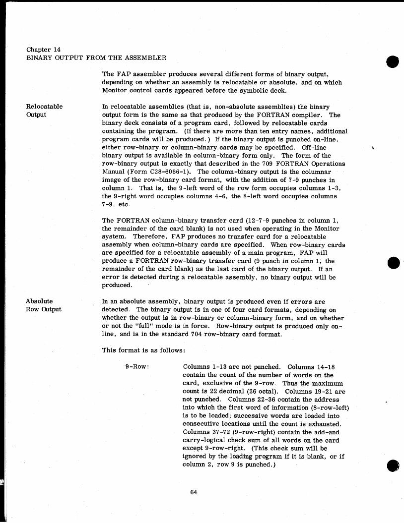
Chapter 14 BINARY OUTPUT FROM THE ASSEMBLER
The FAP assembler produces several different forms of binary output, depending on whether an assembly is relocatable or absolute, and on which Monitor control cards appeared before the symbolic deck.
Relocatable In relocatable assemblies (that is , non-abs olute assemblies) the binary Output output form is the same as that produced by the FORTRAN compiler. The
binary deck consists of a program card, followed by relocatable cards containing the program. (If there are more than ten entry names, additional program cards will be produced. ) If the binary output is punched on-line, either row-binary or column-binary cards may be specified. Off-line binary output i s available in column-binary form only. The form of the row-binary output is exactly that described in the 709 FORTRAN Operations Manual (Form C28-6066-1). The column-binary output is the columnar image of the row-binary card format, with the addition of 7-9 punches in column 1. That is , the 9-left word of the row form occupies columns 1-3, the 9-right word occupies columns 4-6, the 8-left word occupies columns 7-9, etc.
The FORTRAN column-binary transfer card (12-7-9 punches in column 1, the remainder of the card blank) is not used when operating in the Monitor system. Therefore, FAP produces no transfer card for a relocatable assembly when column-binary cards are specified. When row-binary cards a re specified for a relocatable assembly of a main program, FAP will produce a FORTRAN row-binary transfer card (9 punch in column 1, the remainder of the card blank) as the last card of the binary output. If an e r ror is detected during a relocatable assembly, no binary output will be produced. .
Absolute In an absolute assembly, binary output is produced even if e r rors a re Row Output detected. The binary output is in one of four card formats, depending on
whether the output is in row-binary or column-binary form, and on whether or not the "full" mode is in force. Row-binary output is produced only on- line, and is in the standard 704 row-binary card format.
This format is a s follows:
9 -Row : Columns 1-13 a re not punched. Columns 14-18 contain the count of the number of words on the card, exclusive of the 9-row. Thus the maximum count is 22 decimal (26 octal). Columns 19 -21 a re not punched. Columns 22-36 contain the address into which the f i rs t word of information (8-row-left) is to be loaded; successive words a re loaded into consecutive locations until the count is exhausted. Columns 37 -72 (9 -row-right) contain the add-and carry-logical check sum of all words on the card except 9-row-right. (This check sum will be ignored by the loading program if i t is blank, or if column 2, row 9 is punched. )

8 -Row: Columns 1-36 contain the first binary word of information (instruction or data). Columns 37-72 contain the second binary word of information.
7-Row, etc. contain additional binary words of information. The binary deck may also contain transfer cards. A transfer card is a card which is blank except for the address portion of the 9 -left word.
Two 709 loading programs which will load 704 row-binary cards, WDBLl and WDBLUl (SHARE Distribution 535), are available from the SHARE Distribution Agency.
Absolute Column Output
Column-binary cards produced by F A P are in the standard 709 column- binary card format. In this format each word occupies three columns, and is read from top to bottom, then from left to right. The format is a s follows:
Column 1 : Row 12 is blank. Rows 11,0,1,2,3, containthe count of the number of words on this card exclusive of the first word. Thus, the maximum count is 23 decimal (27 octal). Rows 4-6 contain the high-order three bits of the address into which the first word of information (columns 4-6) is to be loaded. Row 7 is punched, row 8 is blank; row 9 is punched.
Column 2 : Rows 12-9 contain the low-order twelve bits of the address into which the first word of information is to be loaded.
Column 3 : Rows 12 -9 contain the twelve -bit add-d-carry- logical check sum of columns, 1, 2, and 4-72.
Columns 4-6 contain the first binary word of information.
Columns 7-9, 10-12, etc. contain additional binary words of information.
The binary deck may also contain transfer cards. A transfer card is blank except for 7- and 9- punches in column 1 and an address punched in rows 4-6 of column 1 and all of column 2.
709 loading programs which will load 709 column-binary cards, WDCBLl and WDCBUl for card loading (SHARE Distribution 527), WD BT2 and WD BTU2 for tape loading (SHARE Distributions 527 and 535), and WDUCLA for card or tape loding (SHARE Distribution 535), may be ordered from the SHARE Distribution agency.
Fullff Output When the "fullff mode has been established in an absolute assembly by the use of a FUL card, binary output will be in one of two formats depending on whether row-binary or column-binary output has been specified. Row- binary YulP output is produced only on-line. The first word of output occupies columns 1-36 of the 9-row, the second word occupies columns
137-72 of the %row, the third word occupies column 1-36 of the 8-row,

and so on, to a maximum of 24 words per card. No control words or check sums are produced by the assembler in "fullff mode.
Column-binary wfull" cards, or card images, contain the first word of output in column 1-3, the second word in columns 4-6, and so on, to a maximum of 24 words per card. No control words or check sums are produced by the assembler in the fffullv mode. There will be 7-9 punches in column 1 onlv if the monrammer arranges for the first word on the
-
card to contain 1's in bit-positions 9 and 11. If these bits are missing, they will not be supplied by the assembler in the "full" mode.
Chapter 1 SUBROUTINES
Since the advent of stored-program computers, programmers have utilized subroutines. A subroutine is a set of program steps, taken as a unit, which performs a task, and which forms a part of a program. Subroutines a re useful in many applications and for many reasons. One reason for using a subroutine is that by doing so a programmer may utilize coding written by someone else, or which he himself has written and forgotten, without having to duplicate the effort that went into producing the coding originally. Another reason is that the effort of debugging a program is substantially reduced if subroutines are used which have been debugged previously. Then too, a programmer, or a whole crew of programmers and analysts may exert great effort to produce a super-efficient subroutine to solve a common problem, whereas if an individual programmer had to solve the problem himself, he would not be able to devote the same amount of time and effort, and would probably arrive at a less efficient solution. Finally, by entering a subroutine from several points in a program, a programmer can make one set of instructions do the work of many, thus saving memory space.
Open and Closed Subroutines
Two types of subroutines are used, "open subroutines" and "closed subroutines. " An open subroutine is a set of instructions inserted into the body of a program and encountered in the normal path of flow. A closed subroutine is , in a sense, a separate program. The main routine using a closed subroutine transfers control to it, and when the subroutine has accomplished its functions, i t returns control to the appropriate point in the main routine. Open subroutines, since they are incorporated directly into the main routine, require no special linkage. Closed subroutines, in contrast, demand special communication facilities. This inconvenience is off-set by the flexibility and economy of storage offered by the closed subroutine, in that repeated references to the subroutine may be made from various points in the main routine. The remainder of this discussion will be devoted to closed subroutines.
Linkages Since a closed subroutine may be entered from different points in the main routine, the main routine must enter the subroutine in such a way that the subroutine will be able to return to the correct point. The instruction or instructions which make this possible form what is called the "linkagev between the main routine and the subroutine. In the 704 and 709 computers, the standard linkage is a Transfer and Set Index instruction which uses index

Calling Sequences
register 4. The instruction * FOR REMARKS
I I OPERATION I I ADDRESS, TAG, DECREMENT/COUNT
I I
appear in successive locations in the main routine following the location of the linkage. Then the beginning and ending instructions of the subroutine might appear as follows :
transfers control to the subroutine, and places in index register 4 the two's complement of the location of the TSX instruction. In order to return to the location following the TSX, the subroutine may use the instruction
* FOR REMARKS
The linkage and the locations containing parameters together form what is called the calling sequence. Typically, the subroutine returns control to the location following the last word of the calling sequence. In FORTRAN,
LOCATION
a parameter appegrs in the address portion of each location of the calling sequence ; the parameter is usually the address of a cell containing the argument needed by the subroutine. The operation portion of a FORTRAN calling-sequence word contains'the binary code for a TSX instruction; the tag bits are zeros. Thus, a FORTRAN calling sequence appears a s follows:
I I 'l 112 6 I I I I I I t
I I I I 1 , I
OPERATION I I ADDRESS, TAG, DECREMENT/COUNT I I
7 8 14\1~116
Often it is necessary for a main routine and a subroutine to communicate with one another. The main routine may have to furnish the subroutine with numbers on which to operate; these numbers are often called arguments r or parameters. Also, the subroutine may produce one or more numbers which are needed by the main routine. For example, a mathematical routine such as SIN will have one argument and will produce one number as its result. In such a case, it is usual for the main routine to place its arguments in various registers of the computer, and for the subroutine also to leave its results in one or more of the registers. However, often there are more arguments, or more results, than there are registers. In this case, the subroutine will usually be written so that the arguments may

FORTRAN Linkages and Calling Sequences
* FOR REMARKS I I
OPERATION I ADDRESS, TAG, DECREMENT/COUNT I I
The number of tagless TSX instructions in the calling sequence is determined by the subroutine; for some subroutines, the length of the calling sequence is variable. (The end of the calling sequence is signalled by the occurrence of something other than a tagless TSX. ) The use of the calling sequence is a powerful tool; the parameters may be the locations of entire arrays, some used by the subroutine, and some produced by it.
Five types of subroutines may be used in FORTRAN. These are built- in functions, arithmetic statement functions, library functions, FUNCTION subprograms, and SUBROUTINE subprograms. The built-in functions, such as ABSF and FLOATF, are listed in the FORTRAN manual. They are compiled as open subroutines within the body of the main routine. Arithmetic statement functions are closed subroutines which are compiled as an integral part of the program in which they appear. Their use is described in the FORTRAN manual. Neither built-in functions nor arithmetic statement functions will be discussed further here.
A library function, such as SINF or SQRTF, has a name terminated by the letter "F". The argument of a library function is placed in the Accumulator by the main routine before control is transferred to the subroutine. If there is a second argument, it is placed in the MQ Register. The calling sequence for a library function consists solely of the linking TSX (which has a tag of 4). A library function produces a single number as its result; this number is left in the Accumulator and control is returned to the instruction following the one-word calling sequence, The FORTRAN compiler is directed to use this calling procedure by the presence of the letter "F" at the end of the function's name; the compiler removes this terminal "F", since it is not present in the corresponding routine in the library.
A FUNCTION subprogram is compiled or assembled separately from the program which calls it. The calling program utilizes the FORTRAN calling sequence described in the preceding section. Thus the number of arguments i s practically unlimited. Like a library function, the FUNCTION subprogram produces a single number as its result; this number is left in the Accumulator, and control is returned to the instruction following the last word of the calling sequence. The FORT-RAN compiler is directed to use this calling procedure by the absence of the letter "F" at the end of the functionts name. Further information regarding FUNCTION subprograms may be found in the 709 FORTRAN manual.
Each of the four types of function subroutines discussed above is called in the same manner from a FORTRAN source program. The name of the
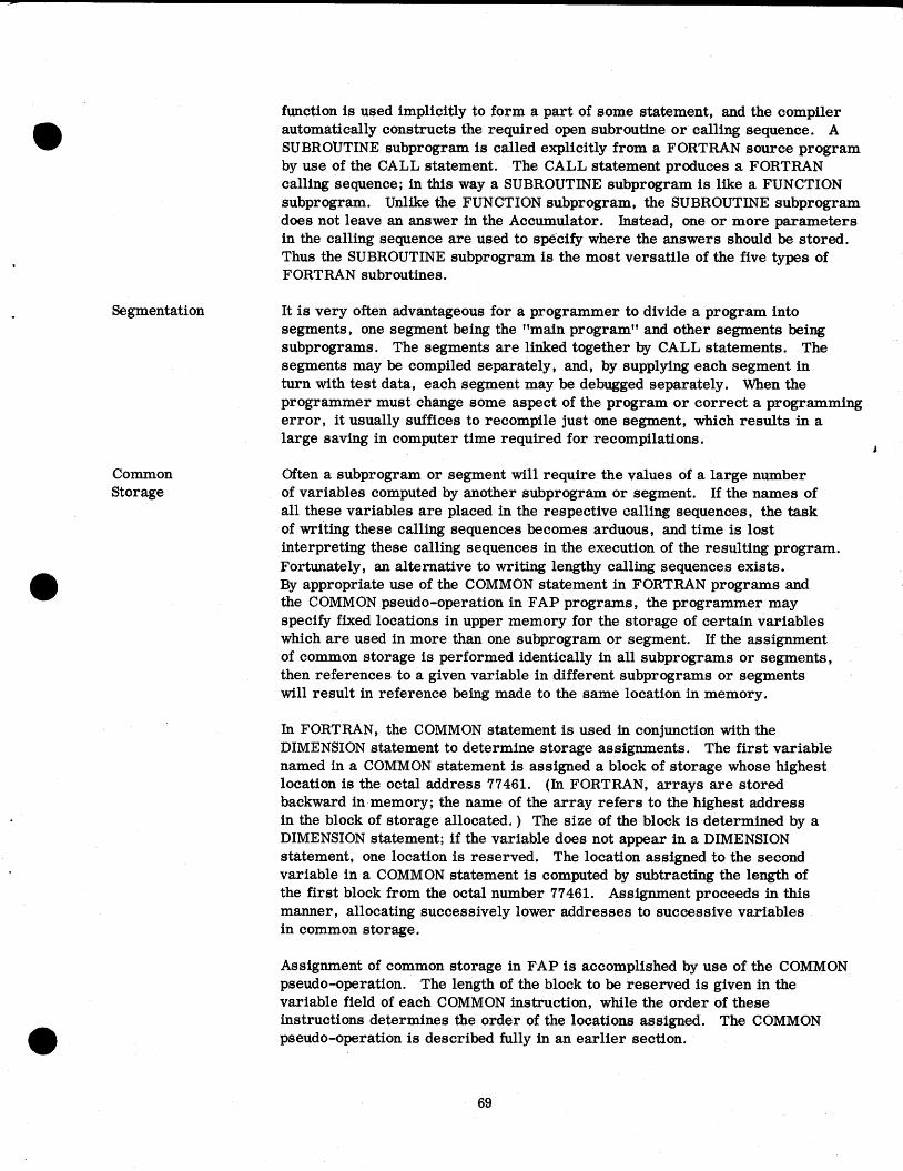
Segmentation
Common Storage
function is used implicitly to form a part of some statement, and the compiler automatically constructs the required open subroutine or calling sequence. A SUBROUTINE subprogram is called explicitly from a FORTRAN source program by use of the CALL statement. The CALL statement produces a FORTRAN calling sequence; in this way a SUBROUTINE subprogram is like a FUNCTION subprogram. Unlike the FUNCTION subprogram, the SUBROUTINE subprogram does not leave an answer in the Accumulator. Instead, one or more parameters in the calling sequence are used to sp6cify where the answers should be stored. Thus the SUBROUTINE subprogram is the most versatile of the five types of FORTRAN subroutines.
It is very often advantageous for a programmer to divide a program into segments, one segment being the "main programv and other segments being subprograms. The segments are linked together by CALL statements. The segments may be compiled separately, and, by supplying each segment in turn with test data, each segment may be debugged separately. When the programmer must change some aspect of the program or correct a programming error , it usually suffices to recompile just one segment, which results in a large saving in computer time required for recompilations.
J
Often a subprogram or segment will require the values of a large number of variables computed by another subprogram or segment. If the names of all these variables are placed in the respective calling sequences, the task of writing these calling sequences becomes arduous, and time is lost interpreting these calling sequences in the execution of the resulting program. Fortunately, an alternative to writing lengthy calling sequences exists. By appropriate use of the COMMON statement in FORTRAN programs and the COMMON pseudo-operation in FAP programs, the programmer may specify fixed locations in upper memory for the storage of certain variables which are used in more than one subprogram or segment. If the assignment of common storage is performed identically in all subprograms or segments, then references to a given variable in different subprograms or segments will result in reference being made to the same location in memory.
In FORTRAN, the COMMON statement is used in conjunction with the DIMENSION statement to determine storage assignments. The first variable named in a COMMON statement is assigned a block of storage whose highest location is the octal address 77461. (In FORTRAN, arrays are stored backward in memory; the name of the array refers to the highest address in the block of storage allocated. ) The size of the block is determined by a DIMENSION statement; if the variable does not appear in a DIMENSION statement, one location is reserved. The location assigned to the second variable in a COMMON statement is computed by subtracting the length of the first block from the octal number 77461. Assignment proceeds in this manner, allocating successively lower addresses to successive variables in common storage.
Assignment of common storage in FAP is accomplished by use of the COMMON pseudo-operation. The length of the block to be reserved is given in the variable field of each COMMON instruction, while the order of these instructions determines the order of the locations assigned. The COMMON pseudo-operation i s described fully in an earlier section.

Relocatable Binary
The various subprograms or segments which make up a complete job a re compiled or assembled individually. The library subroutines are present on the library tape in binary form. In order to execute a job, all the component programs must be loaded into the computer in binary form. The loading operation is performed by the BSS (Binary Symbolic Subroutine) Loader, which depends for its operation on the fact that all programs to be loaded are in the relocatable binarv format. This format is so named because it enables
.I
the loader to relocate the program, that is, to place the program into whatever area of memory is available for it.
The idea of relocation is best explained by use of an example. Consider an ordinary (non-relocatable) program which has been coded to occupy the first 100 locations of memory. Now suppose that it is necessary to move this program so that it occupies locations 1000-1100. First, each instruction and each constant of the program must be moved to occupy a location whose address is 1000 greater than that of the old location. Second, certain of the instructions must be modified, among others, all transfer instructions. The modification is necessary so that references to locations within the program will remain consistent. T'w necessary modification may be performed by adding the number 1000 to the address portion of each instruction or constant which must be modifaed. This modification must not be performed indiscrim- inately, however, sinw n~any instructions, shift instructions, and many constants, among others, do not require modification. Finally, there may be some instructions or constants in which the decrement portion refers to a location in the program. Therefore, it may be necessary to add the number 1000 to the decrement portions of some words. Thus, the process of relocation involves three operations:
1. Each word of the program is moved to a new location.
2. A number, the relocation constant, is added to the address portions of certain words of the program.
3. The relocation constant i s added to the decrement portions of certain words of the program.
In the example above, the relocation constant was 1000. This number is also referred to as the Ifbase address1' or "load address. l1
Occasionally, a program i s found which requires some other form of modification for relocation. For instance, use of complemented locations may require that the relocation ckstant be subtracted from the address or decrement portions of some words. The BSS Loader i s not capable of performing such modification, so such a program must be recoded before being used with FORTRAN programs. If the FAP assembler is instructed to produce coding which cannot be relocated by the BSS loader, a relocation error will be indicated.
As stated before, a program to be loaded by the BSS loader must be in relocatable binary format. Either the program will be punched into cards in this format, or it will consist of a sequence of card images on tape,

Transfer Vector
each card image being the tape equivalent of one binary card. The unique feature of the relocatable binary format is that each card (or card image) contains within i t a sequence of relocation indicator bits. These bits indicate to the BSS Loader which of the address and decrement portions of words on the card are to be modified. A discussion of the relocation indicator bits and of the relocatable binary card format is to be found in the 709 FORTRAN Operations Manual, Form C28-6066-1.
In addition to performing relocation, the BSS Loader also makes possible references between different subprograms. The mechanism by which this reference is made is called t b 'qransfer vectorll or "transfer list. l1 Its use i s best explained by an example. Suppose a job consists of a main program and a subprogram named SUBP. These are compiled separately and brought together in relocatable binary form. The two programs are linked together by a CALL statement in the main program. The question arises, since the subprogram is not present when the main program is compiled, how can the compiler assign the correct address to the linking TSX instruction ? The answer i s that the address of the linking TSX instruction is a location at the beginning of the main program called the main program's transfer vector. The compiler places the BCD code for the name SUBP in this transfer-vector word. When the programs are 4
loaded, the BSS Loader determines the location of the first instruction to be executed in the subprogram, and replaces the transfer-vector word by a transfer to this location. Thus, the linking TSX in the main program transfers control to the transfer-vector word, which is also located in the main program, and this now transfers control to the subprogram. Since index register 4 is set by the linking TSX and is not altered by the transfer -vector instruction, the subprogram may use index register 4 to locate its parameters and return point.
In general, there will be as many words in the transfer vector as there are different subroutine names referenced in the program. Each transfer-vector name will be replaced by an appropriate transfer instruction during loading. The BSS Loader is guided in this replacement process by program cards. Each binary deck begins with a program card. The program card gives the number of locations in the transfer vector, the number of locations in the program, the number of locations of common storage used by the program, and every entry-point name used by the program together with the corres- ponding entry address. A detailed description of the program card is given in the 709 FORTRAN Operations Manual.
The FAP assembler, guided by the ENTRY instruction in the symbolic program, produces a program card automatically. The transfer vector is also produced automatically by FAP, and contains every subroutine name used in a CALL statement or referenced by use of the lt$".
Chapter 2 A BRIEF DESCRIPTION OF THE ASSEMBLY PROCESS
This chapter is written on the presumption that the user of FAP will be better able to keep in mind the capabilities and limitations of the assembler if he is familiar with the basic structure of the assembly program. However,

Parts I and I1 of this manual are complete, and the programmer need not be familiar with the material covered here in order to make full use of FAP.
The assembly process consists of three passes. During the first pass, the symbolic cards are read from the input tape and copied onto the intermediate tape, and values are assigned to all location symbols. These values a re tabulated in a dictionary called the vvsymbol table. l v During the second pass, the symbolic cards are read from the intermediate tape, values are substi- tuted for operation codes and symbols, the assembly listing is written on the output tape, and binary card images are written on the binary intermediate tape. During the third pass, the binary card images are processed; depending on the control cards used, the card images may be written on another binary intermediate tape for BSS-loader processing, written on the peripheral punch tape, or punched on-line.
The first pass is primarily devoted to the construction of the symbol table. The assembler uses a counter called the lvlocation countervv to keep track of the lvnext location to be assigned. l v Initially the location counter is set to zero. When an instruction which is not a pseudo-operation is processed, its location symbol, i f any, is entered into the symbol table together with the current value of the location counter, then the location counter is increased by one. Pseudo-operations affect the location counter in different ways. ORG sets the location counter to a given value. BSS and BES increase the contents of the location counter by a given value. EQU, BOOL, and several other pseudo-operations have no effect on the location counter. Whenever a symbol is encountered in the location field of an instruction, it i s defined. Some pseudo-operations require reference to be made to the symbol table in pass one. When such reference must be made, the symbol referred to must already have been entered in the symbol table. This is the reason for the statement that symbols must be vvpreviously defined. l v In most instruc- tions, the symbols in the variable field are not evaluated until pass two, and hence need not be "previously defined. l v
Little processing occurs in pass one; most instructions are merely copied onto the intermediate tape. Half way through pass one (as decided on the basis of the COUNT card) the assembler rewinds the first intermediate tape and begins writing on the second intermediate tape. If the assembler used only one intermediate tape, time would be lost while the assembler waited for this tape to rewind. Using two intermediate tapes, FAP works with each intermediate tape in turn while the other is rewinding.
At the end of pass one, the assembler sorts the symbol table to make searching more efficient in pass two. During this sort any symbols which have been defined more than once are detected, flagged, and listed. The assembler then begins the second pass. The assembler reads the first intermediate tape, which is now rewound, and fully processes all instructions, using the symbol table constructed in pass one. By the time the assembler has finished processing the instructions on the first intermediate tape, the second intermediate tape should be rewound.
The symbol-defining pseudo-operations are interpreted in the first pass

in order to make entries to the symbol table, They are interpreted again in the second pass in order to enter the value assigned into the assembly listing ,
The storage-allocating pseudo-operations are interpreted in the first pass ? to define the symbol in the location field and to alter the location counter, in the case of BSS and BES, or the common counter, in the case of COMMON.
I
In the second pass, the effect of these pseudo-operations is recorded in the 1
assembly listing, and, in the case of BSS and BES, the binary output is also I
affected. I
The data-generating pseudo-operations are interpreted in the first pass only to the extent necessary to define the symbol in the location field and to determine the number of words generated (which number is added to the location counter). The generated data words are developed when the pseudo- operations are interpreted in the second pass.
Instructions which are not pseudo-operations are not interpreted in the first pass, except to define the symbol, if any, in the location field, and to increase the location counter by one. The operation, address, tag, and decrement bits are all assembled in the second pass.
Subroutine names defined by CALL instructions or by use of the "$" are tabulated in the first pass. The number of different subroutine names so tabulated gives the length of the program's transfer vector. At the end of the first pass the length of the transfer vector is added to the value of every relocatable symbol in the symbol table except those symbols which are themselves subroutine names. The length of the transfer vector, the length of the program, and the lowest address of common storage used are placed in the program card image at the beginning of the second pass. Then the ENTRY instructions are processed to produce the completed program card (or program cards).
When a DUP pseudo-operation is encountered in the first pass, the assembler processes each instruction in the range of the DUP just once, computes the amount by which the location counter has been increased, multiplies this amount by the DUP count, and uses this product to compute the new value of the location counter. In the second pass, the assembler backspaces the intermediate tape and reprocesses the range of the DUP the correct number of times.
Literals are processed in the first pass. Each literal is evaluated to yield a 36-bit data item; these data items are tabulated to form the literal table. As each literal is encountered in the first pass, the literal table is searched to see if it already contains the corresponding data item. If the data item is not present, the literal table is expanded and the data item is added. The literal table is kept in sorted order at all times. When a symbolic instruction containing a literal is written on the intermediate tape, the data item generated by the literal is written on the intermediate tape as an extra word in the record. (The intermediate tapes are written and read in the binary mode for this reason. Ordinarily, a record consists

of fourteen words, but a record for an instruction containing a literal consists of fifteen words. ) In the second pass, the data item is retrieved from the intermediate tape, and the literal table is then used to compute the address to be assigned to the data item. At the end of the second pass, the data items in the literal table are published in the assembly listing and in the binary output. This rather elaborate procedure for handling literals is used because at the beginning of the second pass, the assembler must have already deter- mined how many different literal-data-items are used in the program in order to compute the total length of the program, which must be entered into the program card image.
Chapter 3 THE FAP BCD CHARACTER CODE
Note: The FAP BCD character code is identical to the FORTRAN character code except that the FAP apostrophe is replaced by a redundant minus sign, or dash, in the FORTRAN character code.
CHARACTER BCD CODE (OCTAL) CARD CODE
BLANK 0 1 2 3 4
BLANK 0 1 2 3 4

CHARACTER
W X Y z + (plus) - (minus) / (slash) = (equals)
(apostrophe) (period)
) (right paren. ) $ (dollar sign) * (asterisk) , (comma) ( (left paren. )
BCD CODE (OCTAL) CARD CODE

INDEX
ABS Absolute Assembly Absolute Column Output Absolute Row Output Absolute Symbol Arguments Arithmetic Statement Function Assembly Listing Assembly Process Asterisk (element) Asterisk (indirect addressing) Asterisk (operator) Asterisk (remarks) Base Address BCD BCI BES Binary Output Blank Card BOOL Boolean Expressions BSS BSS Loader Built -In Function CALL Calling Sequence Closed Subroutine Comments Card Comments Field COMMON Common Counter Common Storage Common Symbol Constants COUNT Data Generating Pseudo-Operations DEC Decimal Data Item Decimal Integer Decimal Literal DETAIL Dimension Dollar Sign ($)
Heading Character (see HEAD) Transfer Vector Reference
DUP Duplicately Defined Symbol EJECT Element END
Absolute Assembly Relocatable Assembly
ENTRY E m r Flags
B D E L 0 P R u
ETC EQU Expression
Evaluation Types
Extended Machine Operations Fixed Point Number Floating Point Number FUL "Full" Mode of Binary Output Function Subprogram Generative Pseudo-Operations HEAD
(see HED) Heading Character HED
(see HEAD) Hollerith Literal IFEOF Indirect Addressing Library Function Linkage Linkage Director LIST List-Control Pseudo-Operations Literals c
Literal Table Load Address Loading Programs Location Counter Location Field Location Symbol Machine Operations OCT Octal Data
(see VFD and BOOL) Octal Literal ORG Open Subroutines Operation Field Operator Output
Absolute Relocatable
Page Heading Lines Per Number Title Card
Parameters Prefix Codes Previously Defined Symbols Program Card Program Linking Pseudo-Operations Pseudo-Operations Pseudo-Operations Required in
Every Assembly Relocatable Binary Relocatable Output Relocatable Symbol Relocation
Constant Indicator Bits

REM Remarks Card Secondary Entry Segmentation Select Operation Sense Operations SPACE Standard Error Procedure Storage Allocating Pseudo-Operations Subroutine Reference
(see CALL and Dollar Sign) Subroutine Subprogram Symbol Symbol Conversion Symbol Defining Pseudo-Operations Symbolic Address Symbolic Card Format Symbolic Instruction Symbol Table SYN Table Generating TAPENO TCD Term TITLE Transfer Card Transfer List Transfer Vector
(see CALL and Dollar Sign) Undefined Symbol UNLIST Variable-Channel Tape Operations Variable Field VFD

ADDENDA
Page numbers following headings refer to pages in the text which contain information expanded upon or superseded by information following those he adings .
INTRODUCTION
The FORTRAN Assembly Program has now been extended to include all standard 7090 machine operation codes (including references to channels A-H) as well as the following optional machine instructions (where n is a channel designation): DRS, EAD, EAXM, ECA, ECQ, EDP, E m , EMP, ESB, EST, EUA, LAXM, PSLn, RDCn, SSLn, TRS, ZAC. In addition, FAP includes all standard 704 instructions and may be used to assemble a program for execution on the IBM 704.
Additional changes have been made which are designed to facilitate FAP programming. These are discussed under the following four groupings: Source Deck Arrangement and Processing, Changes to Existing FAP, Additional Pseudo-Operations , and Additional Error Flags.
SOURCE DECK ARRANGEMENT AND PROCESSING
Sequence Checking If a BCD source deck is serialized in columns 73-80, sequencing infor- mation will be checked and any card out of sequence will be listed both on- and off-line. If a group of correctly sequenced cards is inserted in- to a deck out of sequence, only the first card of the group will be listed.
A serialized c&d following a card with all blanks in card columns 73-80 will not be sequence checked.
For purposes of sequencing, a blank is not considered to be zero; it is given the octal value 60.
First Card Group Certain pseudo-operations set the mode of an assembly and provide the (Pages 26,47,53, assembler with required information. These must appear in the first 55,62) card group, which includes all list -control and mode -defining pseudo-
operations and which is terminated by the appearance of either a machine instruction or a symbol-defining, storage-allocating, or data-generating pseudo-operation.
The following pseudo-operations must appear in the first card group: page-title card; COUNT; ENTRY (defines a relocatable subprogram); ABS, FUL, 9LP (defines an absolute assembly); SST.
The following pseudo-operations may appear in the first card group: 704; 7090; DETAIL; EJECT; LBL; LIST; PCC;PRINT; REF; REM; SKP; SPACE; SPC; TITLE; TTL; UNLIST; HED; HEAD; 0PSYN;OPD; OPVFD.

Assembler Changes 'The assembly process consists of two passes. During the first pass, in (Pages 71-74) addition to other functions, sequence checking is performed. During the
second pass, off-line row or column binary output is written directly on the Monitor binary output tape; only if on-line cards are requested will the binary intermediate tape be written a s well.
Following a relocatable assembly in error , the binary card images are erased from the Monitor binary output tape and a labeled "FAILED" card is inserted in their place.
Symbol-defining pseudo-operations are interpreted in the first pass ; the definitions are saved as the fifteenth-word of the intermediate record for listing during the second pass.
CHANGES TO EXISTING FAP
The following changes are either extensions or modifications of infor- mation given in the main text of this manual.
Symbolic Reference Table (Pages 60 and 61)
Transfer Card (Page 59)
Instruction Card Format (Pages 54, 64,65)
Variable Field (-€w 2,331
Table Changes
Printing of undefined symbols and duplicately defined symbols is no longer in the previous form (i. e. , a separate listing). All symbols which w
appear in a location field are now listed with their definitions in a Symbolic Reference table following the program break. The program counter location of each reference to the symbol is also listed. Multiply defined symbols will be flagged "M. " A table of references to undefined symbols, if any, will follow the table of references to defined symbols.
In an absolute assembly, no Transfer card will be provided by the appear- ance of an END card unless a variable field is explicitly stated; this field may be coded as zero.
In an absolute assembly, 23 instructions -per -card output (folded check sum) is no longer provided. Both row and column binary output, on- and off-line, will be in 22 instructions-per-card format.
The variable field of an instruction may now extend to include column 72, in which case a terminating blank is automatically assumed by the assem- bler to be present.
The following additions to tables in the text should be made:
Page 18-Table of PSE and MSE (Type E) Instructions RDCn Reset Data aanne l +0760. . . n352
Page 22-Table of Type B Input/Output Operation Codes Additional Variable Channel Instruction
RDCA Additional Variable Unit Address Instructions
RUNA SDHA SDLA

ETC (Page 44)
CALL (Page 48)
ENTRY (Page 47)
COMMON Break (Page 33)
TAPENO (Page 28)
An ETC card not following a comma followed by a blank will not be recog- nized. The ETC card will be flagged "0" as an illegal operation code.
A CALL statement (or any legal ETC card following it) followed by a comma followed by a blank, and not followed by an ETC card, will generate an additional argument of TSX 0 corresponding to the vacuous field.
Any pseudo-operation permitted in the first card group may precede an ENTRY card.
In a relocatable assembly with COMMON, the COMMON break (which is the last location not used by the program) will be listed as it appears on the Program card.
A TAPENO variable field may contain one of the BCD characters A to H to designate the channel, a tape unit designation from 1 to 10, and either the character llB" or l1Dl1 to denote the mode.
ADDITIONAL PSEUDO-OPERATIONS
No change has been made to pseudo-operations required in every assembly, data-generating pseudo-operations , or program-linking pseudo-operations.
Symbol -Def ining The pseudo-operations used to define symbols are EQU, SYN, BOOL, Pseudo-Operations TAPENO, MAX, and MIX Also included in this group, but not actually
used to define symbols are SST, HEAD, and HED.
MAX
The constituents of a MAX pseudo-instruction are :
1. A symbol, appearing in the location field;
2. The operation code MAX, appearing in the operation field; and
3. A series of expressions, separated by commas, appearing in the variable field ; they must be all absolute, all relocatable, or all common.
This pseudo-operation defines the symbol in the location field as the maximum of the expressions in the variable field.
This is the opposite of MAX; it defines the symbol in the location field as the minimum of the expressions in the variable field.

HEAD (Pages 51,54,56-58)
This operation is not new; the facility, however, has been broadened.
The constituents of the HEAD pseudo-instruction are:
1. Blanks, appearing in the location field;
2. The operation code HEAD, appearing in the operation field; and
3. A series of up to ten single characters (a letter or digit, but not a special character) separated by commas, appearing in the variable field.
The character in the first subfield of the HEAD card variable field is considered to be the heading character for any symbol appearing in the variable fields of the instructions which follow until a subsequent HEAD or HED is given. Each symbol in the location fields of the instructions which follow is headed by all the heading characters appearing in the variable field of the HEAD pseudo-instruction and will so appear in the Symbolic Reference table.
Thus, the use of this instruction will permit reference to a symbol de- fined within a multiply-headed region from an alien headed region.
Heading is now permitted in a relocatable assembly in accordance with the following rules : . 1. If a dollar sign ($) is the first character in a machine operation code
variable field followed by a symbol, this symbol is unheaded and is considered to be a name in the transfer vector.
2. In order to unhead a symbol in a relocatable assembly, a zero must explicity precede the dollar sign.
3. If an ENTRY is headed (e. g. , ENTRY X$ABC) the subroutine may be referred to by means of a headed CALL (e. g . , CALL X$ABC,ARGn), or by a doubly -headed machine operation code (e. g. , CLA $X$ABC); either will cause a proper entry into the transfer vector.
HED (Pages 54,59) - The constituents of. the HED pseudo-instruction are:
1. A symbol (single character letter or digit but not a special character), appearing in column 1.
2. The operation code HED, appearing in the operation field; and
3. Up to nine single characters (a letter or digit, but not a special character) separated by commas, appearing in the variable field.
The effect of HED is the same as HEAD, except that the symbol in the location field is considered to be the heading character for symbols appearing in the variable fields of the following instructions, and the symbols appearing in both the location field and variable field of the HED pseudo-instruction are used to define symbols appearing in the location fields of the following instructions.
The constituents of the SST pseudo-instruction are:
1. Blanks, appearing in the location field;
2. The operation code SST, appearing in the operation field; and
3. Blanks, appearing in the variable field.
Use of the SST pseudo-operation provides for the System Symbol table to be included in the assembly. This table includes definitions in the FORTRAN Common ~nput/Output and Control package. If these defini- tions are to be used, SST must appear in the first card group; otherwise, the System Symbol table will be cleared.
Operation Code- This is a new group of pseudo-operations and includes the following : Defining Pseudo- 704, 7090, OPD, OPSYN, and OPVFD. Operations
704 - The constituents of the 704 pseudo-instruction are:
1. Blanks, appearing in the location field;
2. The operation code 704, appearing in the operation field; and
3. Blanks, appearing in the variable field.
This pseudo-operation sets the mode of an assembly to 704 and causes the flagging of any instructions unique to 7090 with a "9. "
The constituents of this pseudo-instruction are the same as those for 704, except that the operation code is 7090.
The effect of this pseudo-operation is to set the mode of an assembly to 7090.

Instructions unique to 704 are flagged "4. I t Except for 709 drum in- structions (which are in the 704 mode), all 709 instructions are in- cluded in the 7 090 mode.
7090 is the normal mode of assembly.
The constituents of the OPD pseudo-instruction are:
1. A symbol, appearing in the location field;
2. The operation code OPD, appearing in the operation field; and
3. An octal machine operation code definition (see below), appearing in the variable field.
The effect of this operation is to define the symbol appearing in the loca- tion field as the machine operation code defined by the variable field.
OPVFD
The constituents of the OPVFD pseudo -instruction are :
1. A symbol, appearing in the location field;
2. The operation code OPVFD, appearing in the operation field; and
3. One or more subfields as described for the VFD pseudo-instruction (with bit count exactly 36), appearing in the variable field.
The effect of this pseudo-instruction is to assemble the variable field as an octal number and assign this as the machine operation code definition of the symbol appearing in the location field (see Machine Operation Code Definition, below).
OPSY N
The constituents of the OPSYN pseudo-instruction are:
1. A symbol, appearing in the location field;
2. The operation code OPSYN, appearing in the operation field; and
3. A machine operation code (which may have been defined by a prior OPD, OPVFD, or OPSYN), appearing in the variable field.
The effect of this pseudo-operation is to obtain, from the operation table, the octal number to be used for definition of the machine operation code symbol listed in the location field.

MACHINE OPERATION CODE DEFINITION
In order to establish an operation code word for OPD, OPVFD, or OPSYN, an octal number must be created in accordance with the following table:
Octal Designation of Binary Bits Affected Meaning
Sign
Type A operation code
Type B,C,D, or E operation code
Indirect address permitted (for type B operation codes only )
Address required
Tag required
Decrement required
Low order thirteen bits contain flags, not a portion of the operation code (type E or type B 1/0 instruction)
Indirect address permitted (type A instruction)
Non-transmit bit (type A instructions)
Instruction is machine instruction, not pseudo- instruction (bit automati - cally provided for OPD or OPVFD)
Instruction permitted in 704 mode

Octal Designation of Binary Bits Affected Meaning
000000 020000 Instruction permitted in 7090 mode. Note : An instruction must have either or both of the above bits or an I1N"
e r ror flag will appear when the instruction is used.
000000 000002
000000 000001
Example :
Part of operation code if bit 17 is zero
Type C instruction
Type D instruction
In order to define X Y Z as an operation synonymous with CLA, it is possible to write
X Y Z OPSYN CLA
X Y Z OPD
Additional flags, not used for this instruction
Permissible in 704, 7090 modes
Machine operation (automati - cally pr wided)
Low order thirteen bits a re not part of operation code
-Address required; indirect address permitted
Machine operation code

Storage -Allocating The symbols used to allocate storage are BSS, BES , COMMON, ORG, Pseudo-Operations and LOC.
LOC (Page 55) - The constituents of the LOC pseudo-instruction are:
1. A symbol or blanks appearing in the location field;
2. The operation code LOC, appearing in the operation field; and
3. An expression appearing in the variable field.
A new counter called the program counter is established. This counter operates in the same manner as the location counter; however, it may be set separately from the location counter by means of the LOC pseudo- operation. (ORG sets both the program and location counters. ) The load address on a binary card is taken from the location counter, symbol definitions are taken from the program counter.
Any symbol appearing in the variable field must be previously defined or else a "P" flag occurs.
LOC may not appear within the range of a DUP (see page 45).
LOC will never cause the punching of a partial card.
Example :
If a portion of the object program is to be loaded at (ORG) 100018 but is to be executed from (LOC) 400018, the following sequence of instructions may be used to permit symbolic addressing:
L B L ORG TRA LOC
ALPHA CLA S T 0 TRA
B E T A BSS D E L T A BSS GAMMA RNT
TEST,X FOR C L A R I T Y ON L I S T I N G 4096 ALPHA 1 6 3 8 5 B E T A DELTA GAMMA 1 1 12
This would produce the following:
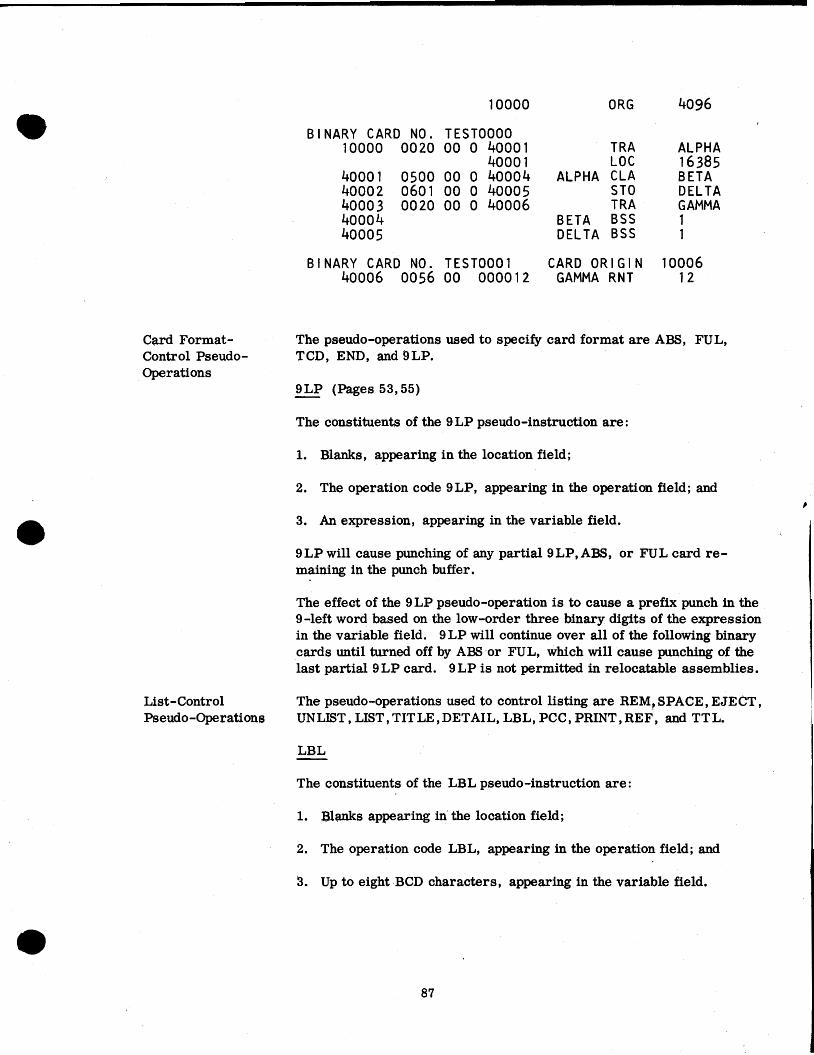
10000 ORG 4096
BINARY CARD NO. TEST0000 10000 0020 00 0 40001 TRA ALPHA
4000 1 LOC 16385 40001 0500 00 0 40004 ALPHA CLA BETA 40002 0601 00 0 40005 ST0 DELTA 40003 0020 00 0 40006 T RA GAMMA 40004 BETA B S S 1 40005 DELTA BSS 1
BINARY CARD NO. TEST0001 CARD ORIGIN 10006 40006 0056 00 000012 GAMMA RNT 12
Card Format- The pseudo-operations used to specify card format are ABS, FUL, Control Pseudo- TCD, END, and SLP. Operations
9LP (Pages 53,55) - The constituents of the 9 LP pseudo-instruction are :
1. Blanks, appearing in the location field;
2. The operation code SLP, appearing in the operation field; and
3. An expression, appearing in the variable field. i
9LP will cause punching of any partial 9LP,ABS, or FUL card re- maining in the punch buffer.
The effect of the 9LP pseudo-operation is to cause a prefix punch in the 9-left word based on the low-order three binary digits of the expression in the variable field. 9 LP will continue over all of the following binary cards until turned off by ABS or FUL, which will cause punching of the last partial 9LP card. 9LP is not permitted in relocatable assemblies.
List-Control The pseudo-operations used to control listing a re REM, SPACE, EJECT, Pseudo-Operations UNLIST , LIST, TITLE , DETAIL, LBL, PCC, PRINT, REF, and TTL.
The constituents of the LBL pseudo-instruction are:
1. Blanks appearing in' the location field;
2. The operation code LBL, appearing in the operation field; and
3. Up to eight BCD characters, appearing in the variable field.

The LBL pseudo-operation will cause serialization of binary cards in columns 73-80. Serialization will begin with the characters appearing in the variable field, left adjusted and filled with terminating zeros. Serialization will be incremented until the right-most non-numeric char- acter is reached, at which time the numeric portion will recycle to zero.
A transfer card will be labeled TRA n, where n is a five octal digit trans- fer address.
A non-blank, non-zero second subfield of the variable field, if it exists, will cause serialization to be listed. If this second subfield consists of a numeric one, only the first use of the label will be listed.
If LBL with listing is included in a relocatable assembly with no ENTRY cards, the message ITPROGRAM CARD" will identify the card so serialized.
If LBL with listing is included for a card governed by LOC, the actual card origin (which may differ from the location on the listing) will be listed.
The constituents of the PCC pseudo-instruction are :
1. Blanks, appearing in the location field;
2. The operation code PCC, appearing in the operation field; and
3. Blanks, appearing in the variable field.
PCC causes listing of the following control cards : TTL, TITLE, SPC, REF, LIST, LBL, SPACE, SKP, EJECT, DETAIL. If any field e r ror i s fldgged, the card will always be listed. PCC will always be listed. Alternag appearances of PCC turn this feature On and Off. The normal mode is Off.
The constituents of the PRINT pseudo-instruction are:
1. Blanks, appearing in the location field;
2. The operation code PRINT, appearing in the operation field; and
3. A string of BCD characters, starting in card column 14.
The effect of the PRINT pseudo-operation is to cause card columns 14-72 to print on-line, followed by a machine halt during the f i rs t pass over the input deck.

REF
The constituents of this pseudo-instruction are:
1. Blanks, appearing in the location field;
2. The operation code RE F, appearing in the operation field; and
3. Blanks, appearing in the variable field.
The effect of REF is to cause deletion of the Symbolic Reference table listing. Multiply defined and undefined symbols will always be listed. REF may occur at any point in the program.
TTL
The constituents of the TT L pseudo-instruction are :
1. Blanks or a decimal integer, appearing in the location field;
2. The operation code TTL, appearing in the operation field; and
3. A string of BCD characters, starting in card column 12.
The effect of TTL is to generate a subheading on the listing. Card columns 11-72 are used in words 4-14 of a subheading which will appear on each page.
The subheading may be overwritten by another TTL. The subheading may be deleted by a TTL 0.
A decimal integer (from 1 to 32767) in the location field, if present, will cause a renumbering of pages beginning with that integer.
Note: A standard pre-processor and post-processor subheading is pro- vided and is separately paginated. Under the pre-processor subheading are listed Pass 1 messages; under the post-processor subheading are listed the COMMON break, Program break, Symbolic Reference table, and the error message.
ADDITIONAL ERROR FLAGS (Pages 12, 13, 26-28, 61)
In addition to all previously existing flags, several new er ror flags have been added. Where appropriate, errors that were flagged by the "Pfl,or "Bv flags may now be flagged by llUll or the new flag llF1' described below. Errors that were flagged "Dl1 are now flagged l1Ml1 (multiply defined sym- bol). This condition is an assembly error. None of the following new flags will cause printing of the message "ERROR IN ABOVE ASSEMBLYn nor will they suspend relocatable binary output.

N Flag - Non- Standard Operation Code
This flag arises through the use of an operation code whicch is defined by the programmer (through use of the OPD O r OPVFD pscudo-operation) and which is not defined for the mode of assembly being used (see 704 and 7090 pseudo-operations).
4 (or 9) Flag - Invalid Operation Code for Mode of Assembly
If a 704 instruction appears in a 7090 assembly (see 7090 pseudo-operation), it will be flagged "4"; if a 7090 instruction appears in a 704 assembly (see 704 pseudo-operation), it will be flagged "9. " i
A Flag - Missing Address Field
T Flag - Missing Tag Field
D Flag - Missing or Improper Decrement Field
I Flag - Indirect Address Not Permitted
F Flag - Field *
Flag
This flag; will appear whenever the address field of a machine instruction or variable field of a pseudo-instruction is expected and is missing.
This flag will appear whenever a tag field is expected and is missing. S&!&4mW
This flag will appear whenever a decrement field is expected and is missing, a decrement field is provided for a type B or E instruction, or a decrement field longer than 6 bits is provided for a type C in- struction. Assembly of decrement fields in type B or E instructions is provided for compatibility with existing FAP programs ; this pro- vision may be discontinued in a later version of the assembler. There- fore, it is recommended that such instructions be corrected as they are encountered.
This flag appears when a decrement field in a type B or type C instruc- tion appears to be an indirect address, or indirect addressing has been specified by an asterisk for ah operation code which is not permitted indirect addressing.
This flag will appear either for an excessive field in a machine or pseudo-instruction or an improper field in a pseudo-instruction.
Excessive fields in type D instructions will be flagged "Fit and will not result in additional bits in the generated machine word.
Certain improper fields in pseudo-instructions, which were formerly flagged as phase errors, will now be flagged "F" and will not cause binary output to be deleted. Instructions included are MAX, MIN, and SYN. ,
Example :
BETA SYN ALPHA
If ALPHA has not been previously defined, this instruction will be flagged "F. " BETA will remain undefined and any reference to BETA will be flagged "U" which will cause relocatable binary output to be deleted.
m! International Business Machines Corporation Data Processing Division, 1 1 2 East Post Road, White Plains, N. Y.