Embed Size (px)
Citation preview

FortiOS Handbook VoIP Solutions: SIP for FortiOS 5.0
FortiOS Handbook - VoIP Solutions: SIP for FortiOS 5.0
November 13, 2012
01-500-99686-20121113
Copyright© 2012 Fortinet, Inc. All rights reserved. Fortinet®, FortiGate®, and FortiGuard®, are
registered trademarks of Fortinet, Inc., and other Fortinet names herein may also be trademarks
of Fortinet. All other product or company names may be trademarks of their respective owners.
Performance metrics contained herein were attained in internal lab tests under ideal conditions,
and performance may vary. Network variables, different network environments and other
conditions may affect performance results. Nothing herein represents any binding commitment
by Fortinet, and Fortinet disclaims all warranties, whether express or implied, except to the
extent Fortinet enters a binding written contract, signed by Fortinet’s General Counsel, with a
purchaser that expressly warrants that the identified product will perform according to the
performance metrics herein. For absolute clarity, any such warranty will be limited to
performance in the same ideal conditions as in Fortinet’s internal lab tests. Fortinet disclaims in
full any guarantees. Fortinet reserves the right to change, modify, transfer, or otherwise revise
this publication without notice, and the most current version of the publication shall be
applicable.
Technical Documentation docs.fortinet.com
Knowledge Base kb.fortinet.com
Customer Service & Support support.fortinet.com
Training Services training.fortinet.com
FortiGuard fortiguard.com
Document Feedback [email protected]
Table of Contents
Change Log....................................................................................................... 6
Introduction....................................................................................................... 7
How this guide is organized..................................................................................... 7
FortiGate VoIP solutions: SIP .......................................................................... 8
SIP overview ............................................................................................................ 8
Common SIP VoIP configurations ........................................................................... 9
Peer to peer configuration ................................................................................. 9
SIP proxy server configuration......................................................................... 10
SIP redirect server configuration ..................................................................... 10
SIP registrar configuration ............................................................................... 11
SIP with a FortiGate unit .................................................................................. 12
SIP messages and media protocols ...................................................................... 14
SIP request messages ..................................................................................... 16
SIP response messages .................................................................................. 17
SIP message start line ..................................................................................... 19
SIP headers...................................................................................................... 19
The SIP message body and SDP session profiles........................................... 21
Example SIP messages ................................................................................... 23
The SIP session helper .......................................................................................... 24
SIP session helper configuration overview ...................................................... 25
Configuration example: SIP session helper in Transparent Mode................... 27
SIP session helper diagnose commands......................................................... 30
The SIP ALG .......................................................................................................... 31
SIP ALG configuration overview ...................................................................... 33
Conflicts between the SIP ALG and the session helper .................................. 36
Stateful SIP tracking, call termination, and session inactivity timeout ............ 37
SIP and RTP/RTCP .......................................................................................... 39
How the SIP ALG creates RTP pinholes.......................................................... 39
Configuration example: SIP in Transparent Mode........................................... 41
RTP enable/disable (RTP bypass).................................................................... 44
Opening and closing SIP register, contact, via and record-route pinholes ......................................................................................................... 45
Accepting SIP register responses.................................................................... 46
Page 3
How the SIP ALG performs NAT ........................................................................... 46
Source address translation .............................................................................. 47
Destination address translation ....................................................................... 47
Call Re-invite messages .................................................................................. 48
How the SIP ALG translates IP addresses in SIP headers .............................. 48
How the SIP ALG translates IP addresses in the SIP body............................. 50
SIP NAT scenario: source address translation (source NAT)........................... 51
SIP NAT scenario: destination address translation (destination NAT) ............. 53
SIP NAT configuration example: source address translation (source NAT) .................................................................................................. 55
SIP NAT configuration example: destination address translation (destination NAT) ........................................................................................... 58
Additional SIP NAT scenarios .......................................................................... 61
NAT with IP address conservation................................................................... 63
Controlling how the SIP ALG NATs SIP contact header line addresses ......... 64
Controlling NAT for addresses in SDP lines .................................................... 65
Translating SIP session destination ports........................................................ 65
Translating SIP sessions to multiple destination ports .................................... 67
Adding the original IP address and port to the SIP message header after NAT........................................................................................................ 68
Enhancing SIP pinhole security ............................................................................. 68
Hosted NAT traversal............................................................................................. 71
Configuration example: Hosted NAT traversal for calls between SIP Phone A and SIP Phone B............................................................................. 72
Hosted NAT traversal for calls between SIP Phone A and SIP Phone C......................................................................................................... 76
Restricting the RTP source IP.......................................................................... 76
SIP over IPv6 ......................................................................................................... 77
Deep SIP message inspection............................................................................... 77
Actions taken when a malformed message line is found ................................ 78
Logging and statistics...................................................................................... 79
Deep SIP message inspection best practices ................................................. 79
Configuring deep SIP message inspection...................................................... 79
Blocking SIP request messages ............................................................................ 82
SIP rate limiting...................................................................................................... 84
Limiting the number of SIP dialogs accepted by a security policy.................. 85
SIP logging and DLP archiving .............................................................................. 86
Inspecting SIP over SSL/TLS (secure SIP) ............................................................ 86
Adding the SIP server and client certificates ................................................... 87
Adding SIP over SSL/TLS support to a VoIP profile........................................ 88
SIP and HA: session failover and geographic redundancy ................................... 88
SIP geographic redundancy ............................................................................ 89
Support for RFC 2543-compliant branch parameters ..................................... 90
SIP and IPS............................................................................................................ 91
Fortinet Technologies Inc. Page 4 FortiOS Handbook - VoIP Solutions: SIP for FortiOS 5.0
SIP debugging ....................................................................................................... 91
SIP debug log format ....................................................................................... 91
SIP-proxy filter per VDOM ............................................................................... 92
SIP-proxy filter command ................................................................................ 93
SIP debug log filtering...................................................................................... 93
SIP debug setting ............................................................................................ 94
Display SIP rate-limit data ............................................................................... 94
Index ................................................................................................................ 96
Fortinet Technologies Inc. Page 5 FortiOS Handbook - VoIP Solutions: SIP for FortiOS 5.0
Change Log
Date Change Description
2012-11-13 New FortiOS 5.0 release.
Page 6
Introduction
This FortiOS Handbook chapter contains detailed information about how FortiGate units
processes SIP VoIP calls and how to configure the FortiGate unit to apply security features to
SIP calls. This document all describes all FortiGate SIP configuration options and contains
detailed configuration examples. Future versions of this document will include more and more
configuration examples and more information about SIP functionality.
How this guide is organized
This FortiOS Handbook chapter contains the following sections:
FortiGate VoIP solutions: SIP describes FortiGate SIP support.
This document uses numeric IP addresses for all SIP end points. SIP addresses can also use
domain names instead of addresses. For the example, the following SIP addresses could refer
to the same SIP end point:
[email protected]@example.com
Page 7
FortiGate VoIP solutions: SIP
This chapter includes the following sections:
• SIP overview
• Common SIP VoIP configurations
• SIP messages and media protocols
• The SIP session helper
• The SIP ALG
• How the SIP ALG performs NAT
• Enhancing SIP pinhole security
• Hosted NAT traversal
• SIP over IPv6
• Deep SIP message inspection
• Blocking SIP request messages
• SIP rate limiting
• SIP logging and DLP archiving
• Inspecting SIP over SSL/TLS (secure SIP)
• SIP and HA: session failover and geographic redundancy
• SIP and IPS
• SIP debugging
SIP overview
The Session Initiation Protocol (SIP) is an IETF application layer signaling protocol used for
establishing, conducting, and terminating multiuser multimedia sessions over TCP/IP networks
using any media. SIP is often used for Voice over IP (VoIP) calls but can be used for establishing
streaming communication between end points.
SIP employs a request and response transaction model similar to HTTP for communicating
between endpoints. SIP sessions being with a SIP client sending a SIP request message to
another client to initiate a multimedia session. The other client responds with a SIP response
message. Using these request and response messages, the clients engage in a SIP dialog to
negotiate how to communicate and then start, maintain, and end the communication session.
SIP commonly uses TCP or UDP port 5060 and/or 5061. Port 5060 is used for non-encrypted
SIP signaling sessions and port 5061 is typically used for SIP sessions encrypted with SSL or
TLS.
Devices involved in SIP communications are called SIP User Agents (UAs) (also sometimes
called a User Element (UE)). UAs include User Agent Clients (UACs) that communicate with
each other and User Agent Servers (UASs) that facilitate communication between UACs. For a
VoIP application, an example of a UAC would be a SIP phone and an example of a UAS would
be a SIP proxy server.
Page 8
A SIP message contain headers that include client and server names and addresses required
for the communication sessions. The body of a SIP message contains Session Description
Protocol (SDP) statements that establish the media communication (port numbers, protocols
and codecs) that the SIP UAs use. SIP VoIP most commonly uses the Real Time Protocol (RTP)
and the Real Time Control Protocol (RTCP) for voice communication. Once the SIP dialog
establishes the SIP call the VoIP stream can run independently, although SIP messages can
affect the VoIP stream by changing port numbers or addresses and by ending it.
Once SIP communication and media settings are established, the UAs communicate with each
using the established media settings. When the communication session is completed, one of
the UAs ends the session by sending a final SIP request message and the other UA sends a SIP
response message and both UAs end the SIP call and stop the media stream.
FortiGate units provide security for SIP communications using the SIP session helper and the
SIP ALG:
• The SIP session-helper provides basic high-performance support for SIP calls passing
through the FortiGate unit by opening SIP and RTP pinholes and performing source and
destination IP address and port translation for SIP and RTP packets and for the IP addresses
and port numbers in the SIP headers and the SDP body of the SIP messages. For more
about the SIP session helper, see “The SIP session helper” on page 24.
• The SIP Application Layer Gateway (ALG) provides the same features as the session helper
plus additional advanced features such as deep SIP message inspection, SIP logging, SIP
IPv6 support, SIP message checking, HA failover of SIP sessions, and SIP rate limiting. For
more about the SIP ALG, see “The SIP ALG” on page 31.
There are a large number of SIP-related Internet Engineering Task Force (IETF) documents
(Request for Comments) that define behavior of SIP and related applications. FortiGate units
provide complete support of RFC 3261 for SIP, RFC 4566 for SDP and RFC 3262 for Provisional
Response Acknowledgement (PRACK). FortiGate units also provide support for other SIP and
SIP-related RFCs and performs “Deep SIP message inspection” on page 77 for SIP statements
defined in other SIP RFCs.
Common SIP VoIP configurations
This section describes some common SIP VoIP configurations and simplified SIP dialogs for
these configurations. This section also shows some examples of how adding a FortiGate unit
affects SIP processing.
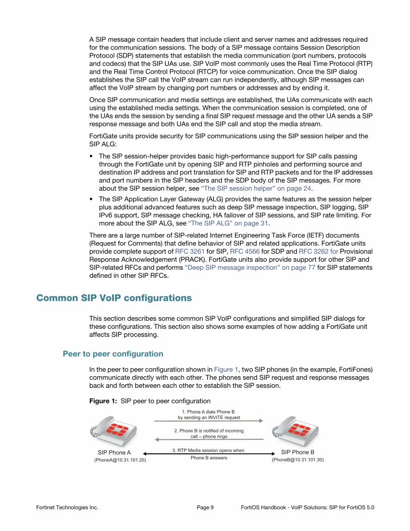
Peer to peer configuration
In the peer to peer configuration shown in Figure 1, two SIP phones (in the example, FortiFones)
communicate directly with each other. The phones send SIP request and response messages
back and forth between each other to establish the SIP session.
Figure 1: SIP peer to peer configuration
3. RTP Media session opens when
Phone B answers
1. Phone A dials Phone B by sending an INVITE request
2. Phone B is notified of incomingcall – phone rings
SIP Phone A SIP Phone B([email protected])([email protected])
Fortinet Technologies Inc. Page 9 FortiOS Handbook - VoIP Solutions: SIP for FortiOS 5.0
Peer to peer configurations are not very common because they require the SIP phones to keep
track of the names and addresses of all of the other SIP phones that they can communicate
with. In most cases a SIP proxy or re-direct server maintains addresses of a large number of SIP
phones and a SIP phone starts a call by contacting the SIP proxy server.
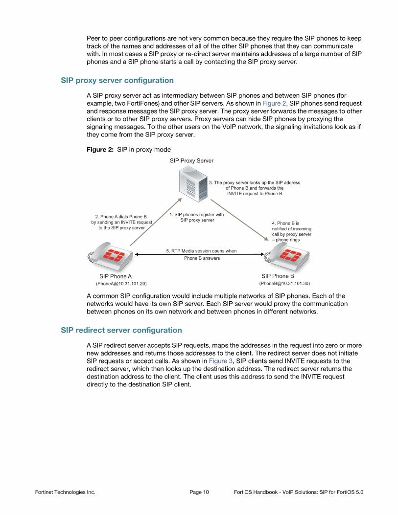
SIP proxy server configuration
A SIP proxy server act as intermediary between SIP phones and between SIP phones (for
example, two FortiFones) and other SIP servers. As shown in Figure 2, SIP phones send request
and response messages the SIP proxy server. The proxy server forwards the messages to other
clients or to other SIP proxy servers. Proxy servers can hide SIP phones by proxying the
signaling messages. To the other users on the VoIP network, the signaling invitations look as if
they come from the SIP proxy server.
Figure 2: SIP in proxy mode
A common SIP configuration would include multiple networks of SIP phones. Each of the
networks would have its own SIP server. Each SIP server would proxy the communication
between phones on its own network and between phones in different networks.
SIP redirect server configuration
A SIP redirect server accepts SIP requests, maps the addresses in the request into zero or more
new addresses and returns those addresses to the client. The redirect server does not initiate
SIP requests or accept calls. As shown in Figure 3, SIP clients send INVITE requests to the
redirect server, which then looks up the destination address. The redirect server returns the
destination address to the client. The client uses this address to send the INVITE request
directly to the destination SIP client.
SIP Phone A SIP Phone B
SIP Proxy Server
([email protected])([email protected])
1. SIP phones register with SIP proxy server
5. RTP Media session opens when Phone B answers
2. Phone A dials Phone B by sending an INVITE request
to the SIP proxy server
3. The proxy server looks up the SIP addressof Phone B and forwards theINVITE request to Phone B
4. Phone B isnotified of incomingcall by proxy server– phone rings
P Ph BB
Fortinet Technologies Inc. Page 10 FortiOS Handbook - VoIP Solutions: SIP for FortiOS 5.0
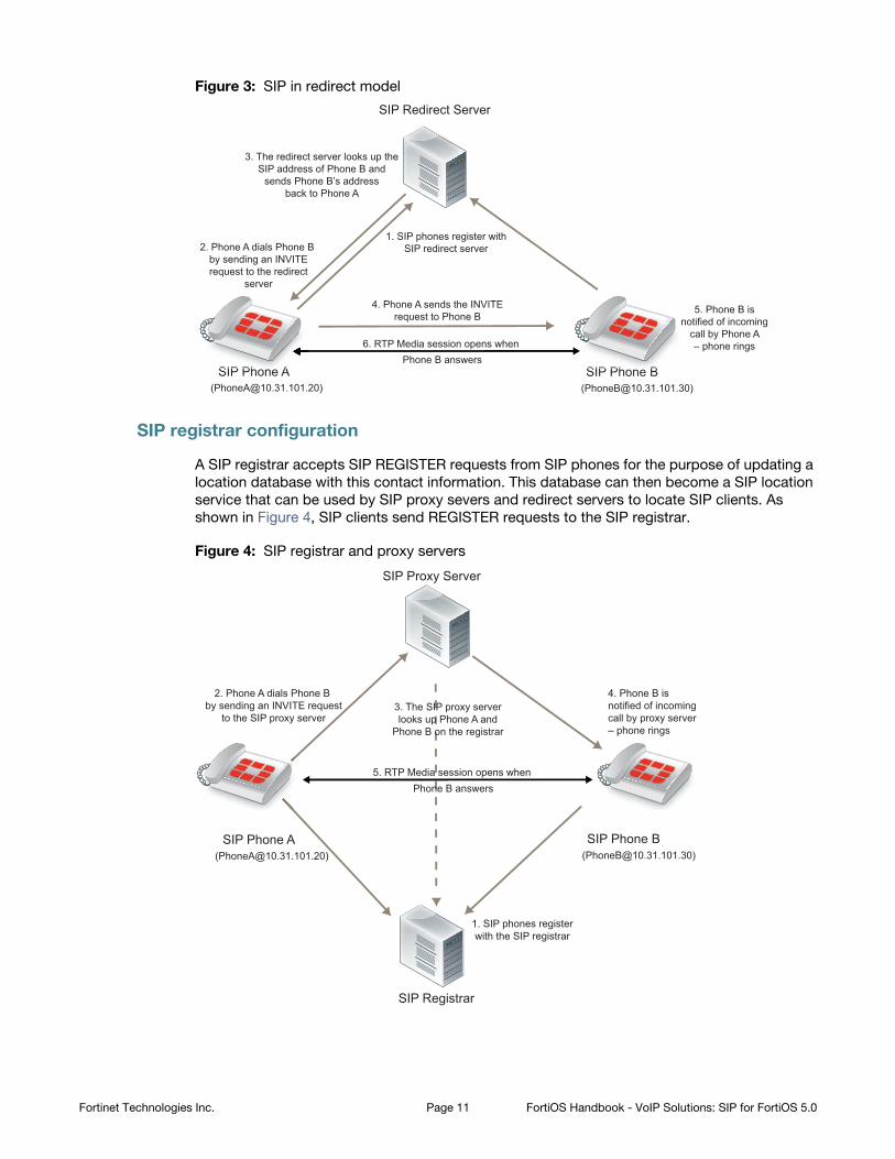
Figure 3: SIP in redirect model
SIP registrar configuration
A SIP registrar accepts SIP REGISTER requests from SIP phones for the purpose of updating a
location database with this contact information. This database can then become a SIP location
service that can be used by SIP proxy severs and redirect servers to locate SIP clients. As
shown in Figure 4, SIP clients send REGISTER requests to the SIP registrar.
Figure 4: SIP registrar and proxy servers
SIP Phone A SIP Phone B ([email protected])([email protected])
1. SIP phones register withSIP redirect server
SIP Redirect Server
3. The redirect server looks up theSIP address of Phone B and
sends Phone B’s addressback to Phone A
5. Phone B isnotified of incoming
call by Phone A– phone rings
4. Phone A sends the INVITErequest to Phone B
6. RTP Media session opens when Phone B answers
2. Phone A dials Phone B by sending an INVITErequest to the redirect
server
SIP PPh AA SIP Phh BBB
n
SIP Phone A SIP Phone B
SIP Proxy Server
SIP Registrar
([email protected])([email protected])
1. SIP phones registerwith the SIP registrar
5. RTP Media session opens when Phone B answers
2. Phone A dials Phone B by sending an INVITE request
to the SIP proxy server3. The SIP proxy serverlooks up Phone A and
Phone B on the registrar
4. Phone B isnotified of incomingcall by proxy server– phone rings
Fortinet Technologies Inc. Page 11 FortiOS Handbook - VoIP Solutions: SIP for FortiOS 5.0
SIP with a FortiGate unit
Depending on your security requirements and network configuration FortiGate units may be in
many different places in a SIP configuration. This section shows a few examples.
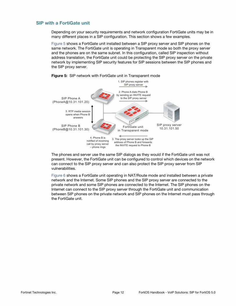
Figure 5 shows a FortiGate unit installed between a SIP proxy server and SIP phones on the
same network. The FortiGate unit is operating in Transparent mode so both the proxy server
and the phones are on the same subnet. In this configuration, called SIP inspection without
address translation, the FortiGate unit could be protecting the SIP proxy server on the private
network by implementing SIP security features for SIP sessions between the SIP phones and
the SIP proxy server.
Figure 5: SIP network with FortiGate unit in Transparent mode
The phones and server use the same SIP dialogs as they would if the FortiGate unit was not
present. However, the FortiGate unit can be configured to control which devices on the network
can connect to the SIP proxy server and can also protect the SIP proxy server from SIP
vulnerabilities.
Figure 6 shows a FortiGate unit operating in NAT/Route mode and installed between a private
network and the Internet. Some SIP phones and the SIP proxy server are connected to the
private network and some SIP phones are connected to the Internet. The SIP phones on the
Internet can connect to the SIP proxy server through the FortiGate unit and communication
between SIP phones on the private network and SIP phones on the Internet must pass through
the FortiGate unit.
1. SIP phones register with SIP proxy server
2. Phone A dials Phone B by sending an INVITE request
to the SIP proxy server
3. The proxy server looks up the SIP address of Phone B and forwards
the INVITE request to Phone B
4. Phone B isnotified of incomingcall by proxy server
– phone rings
5. RTP media sessionopens when Phone B
answers
FortiGate unitin Transparent mode
SIP proxy server10.31.101.50
SIP Phone A([email protected])
SIP Phone B([email protected])
FortrttiGiGiGGate unit
Fortinet Technologies Inc. Page 12 FortiOS Handbook - VoIP Solutions: SIP for FortiOS 5.0
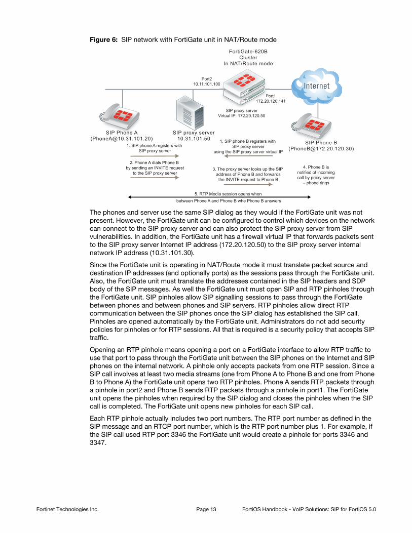
Figure 6: SIP network with FortiGate unit in NAT/Route mode
The phones and server use the same SIP dialog as they would if the FortiGate unit was not
present. However, the FortiGate unit can be configured to control which devices on the network
can connect to the SIP proxy server and can also protect the SIP proxy server from SIP
vulnerabilities. In addition, the FortiGate unit has a firewall virtual IP that forwards packets sent
to the SIP proxy server Internet IP address (172.20.120.50) to the SIP proxy server internal
network IP address (10.31.101.30).
Since the FortiGate unit is operating in NAT/Route mode it must translate packet source and
destination IP addresses (and optionally ports) as the sessions pass through the FortiGate unit.
Also, the FortiGate unit must translate the addresses contained in the SIP headers and SDP
body of the SIP messages. As well the FortiGate unit must open SIP and RTP pinholes through
the FortiGate unit. SIP pinholes allow SIP signalling sessions to pass through the FortiGate
between phones and between phones and SIP servers. RTP pinholes allow direct RTP
communication between the SIP phones once the SIP dialog has established the SIP call.
Pinholes are opened automatically by the FortiGate unit. Administrators do not add security
policies for pinholes or for RTP sessions. All that is required is a security policy that accepts SIP
traffic.
Opening an RTP pinhole means opening a port on a FortiGate interface to allow RTP traffic to
use that port to pass through the FortiGate unit between the SIP phones on the Internet and SIP
phones on the internal network. A pinhole only accepts packets from one RTP session. Since a
SIP call involves at least two media streams (one from Phone A to Phone B and one from Phone
B to Phone A) the FortiGate unit opens two RTP pinholes. Phone A sends RTP packets through
a pinhole in port2 and Phone B sends RTP packets through a pinhole in port1. The FortiGate
unit opens the pinholes when required by the SIP dialog and closes the pinholes when the SIP
call is completed. The FortiGate unit opens new pinholes for each SIP call.
Each RTP pinhole actually includes two port numbers. The RTP port number as defined in the
SIP message and an RTCP port number, which is the RTP port number plus 1. For example, if
the SIP call used RTP port 3346 the FortiGate unit would create a pinhole for ports 3346 and
3347.
5. RTP Media session opens when between Phone A and Phone B whe Phone B answers
Port1172.20.120.141
SIP proxy serverVirtual IP: 172.20.120.50
Port210.11.101.100
FortiGate-620BCluster
In NAT/Route mode
1. SIP phone B registers with SIP proxy server
using the SIP proxy server virtual IP
2. Phone A dials Phone B by sending an INVITE request
to the SIP proxy server3. The proxy server looks up the SIP
address of Phone B and forwardsthe INVITE request to Phone B
4. Phone B isnotified of incomingcall by proxy server
– phone rings
SIP proxy server10.31.101.50
SIP Phone A([email protected])
SIP Phone B([email protected])1. SIP phone A registers with
SIP proxy server
172.20.Po
1172 20
0
SISIPPP PhPhPhPhPhh B
SIP PhPhhhhP onononee A
Fortinet Technologies Inc. Page 13 FortiOS Handbook - VoIP Solutions: SIP for FortiOS 5.0
SIP messages and media protocols
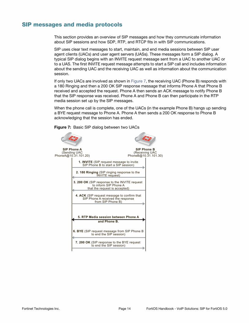
This section provides an overview of SIP messages and how they communicate information
about SIP sessions and how SDP, RTP, and RTCP fits in with SIP communications.
SIP uses clear text messages to start, maintain, and end media sessions between SIP user
agent clients (UACs) and user agent servers (UASs). These messages form a SIP dialog. A
typical SIP dialog begins with an INVITE request message sent from a UAC to another UAC or
to a UAS. The first INVITE request message attempts to start a SIP call and includes information
about the sending UAC and the receiving UAC as well as information about the communication
session.
If only two UACs are involved as shown in Figure 7, the receiving UAC (Phone B) responds with
a 180 Ringing and then a 200 OK SIP response message that informs Phone A that Phone B
received and accepted the request. Phone A then sends an ACK message to notify Phone B
that the SIP response was received. Phone A and Phone B can then participate in the RTP
media session set up by the SIP messages.
When the phone call is complete, one of the UACs (in the example Phone B) hangs up sending
a BYE request message to Phone A. Phone A then sends a 200 OK response to Phone B
acknowledging that the session has ended.
Figure 7: Basic SIP dialog between two UACs
SIP Phone A(Sending UAC
SIP Phone B(Receiving UAC
1. INVITE (SIP request message to inviteSIP Phone B to start a SIP session)
4. ACK (SIP request message to confirm thatSIP Phone A received the response
from SIP Phone B)
5. RTP Media session between Phone Aand Phone B.
3. 200 OK (SIP response to the INVITE request to inform SIP Phone A
that the request is accepted)
2. 180 Ringing (SIP ringing response to the INVITE request)
6. BYE (SIP request message from SIP Phone Bto end the SIP session)
7. 200 OK (SIP response to the BYE request to end the SIP session)
Fortinet Technologies Inc. Page 14 FortiOS Handbook - VoIP Solutions: SIP for FortiOS 5.0
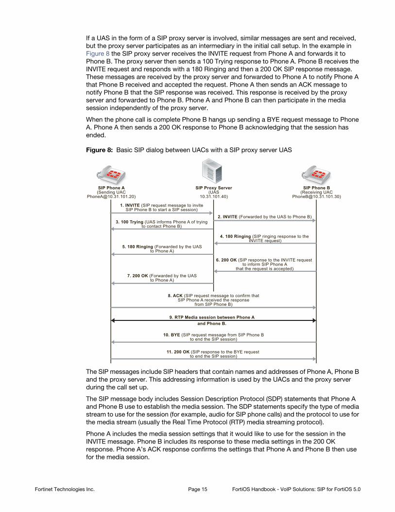
If a UAS in the form of a SIP proxy server is involved, similar messages are sent and received,
but the proxy server participates as an intermediary in the initial call setup. In the example in
Figure 8 the SIP proxy server receives the INVITE request from Phone A and forwards it to
Phone B. The proxy server then sends a 100 Trying response to Phone A. Phone B receives the
INVITE request and responds with a 180 Ringing and then a 200 OK SIP response message.
These messages are received by the proxy server and forwarded to Phone A to notify Phone A
that Phone B received and accepted the request. Phone A then sends an ACK message to
notify Phone B that the SIP response was received. This response is received by the proxy
server and forwarded to Phone B. Phone A and Phone B can then participate in the media
session independently of the proxy server.
When the phone call is complete Phone B hangs up sending a BYE request message to Phone
A. Phone A then sends a 200 OK response to Phone B acknowledging that the session has
ended.
Figure 8: Basic SIP dialog between UACs with a SIP proxy server UAS
The SIP messages include SIP headers that contain names and addresses of Phone A, Phone B
and the proxy server. This addressing information is used by the UACs and the proxy server
during the call set up.
The SIP message body includes Session Description Protocol (SDP) statements that Phone A
and Phone B use to establish the media session. The SDP statements specify the type of media
stream to use for the session (for example, audio for SIP phone calls) and the protocol to use for
the media stream (usually the Real Time Protocol (RTP) media streaming protocol).
Phone A includes the media session settings that it would like to use for the session in the
INVITE message. Phone B includes its response to these media settings in the 200 OK
response. Phone A’s ACK response confirms the settings that Phone A and Phone B then use
for the media session.
SIP Phone A(Sending UAC
SIP Phone B(Receiving UAC
SIP Proxy Server(UAS
10.31.101.40)
1. INVITE (SIP request message to inviteSIP Phone B to start a SIP session)
2. INVITE (Forwarded by the UAS to Phone B)
8. ACK (SIP request message to confirm thatSIP Phone A received the response
from SIP Phone B)
7. 200 OK (Forwarded by the UASto Phone A)
6. 200 OK (SIP response to the INVITE request to inform SIP Phone A
that the request is accepted)
3. 100 Trying (UAS informs Phone A of tryingto contact Phone B)
4. 180 Ringing (SIP ringing response to the INVITE request)
5. 180 Ringing (Forwarded by the UASto Phone A)
10. BYE (SIP request message from SIP Phone Bto end the SIP session)
11. 200 OK (SIP response to the BYE request to end the SIP session)
9. RTP Media session between Phone Aand Phone B.
Fortinet Technologies Inc. Page 15 FortiOS Handbook - VoIP Solutions: SIP for FortiOS 5.0
Hardware accelerated RTP processing
FortiGate units can offload RTP packet processing to network processor (NP) interfaces. This
acceleration greatly enhance the overall throughput and resulting in near speed RTP
performance.
SIP request messages
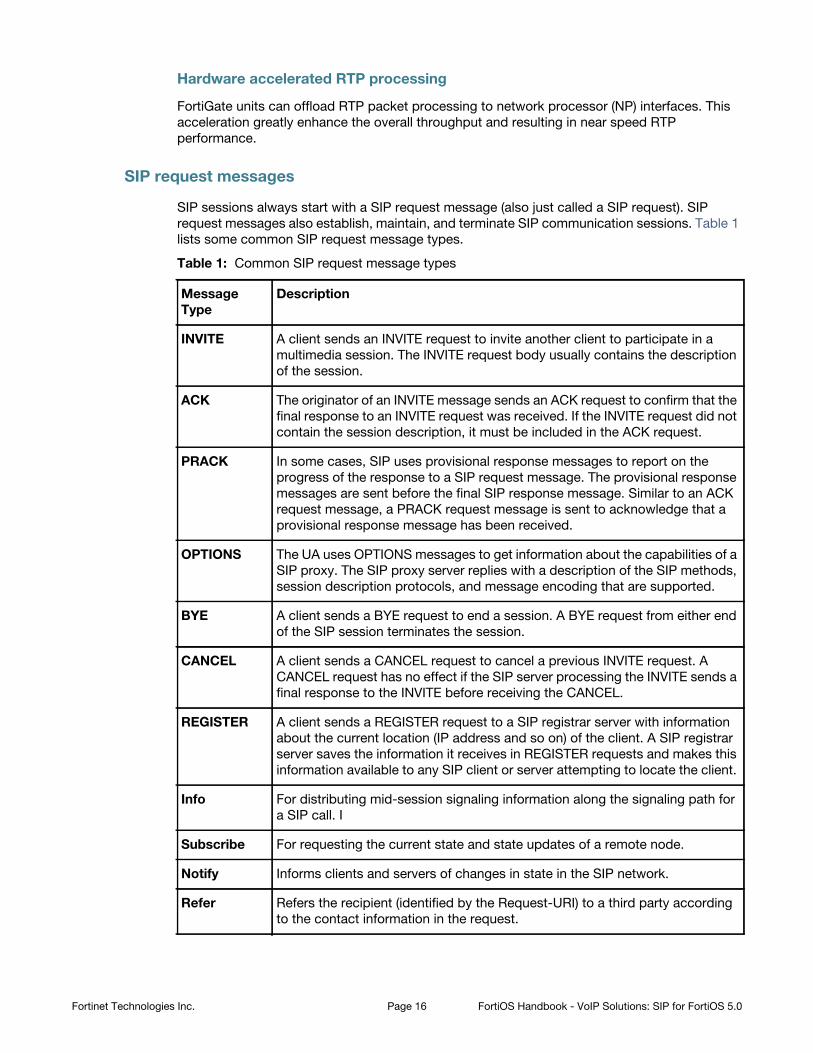
SIP sessions always start with a SIP request message (also just called a SIP request). SIP
request messages also establish, maintain, and terminate SIP communication sessions. Table 1
lists some common SIP request message types.
Table 1: Common SIP request message types
Message
Type
Description
INVITE A client sends an INVITE request to invite another client to participate in a
multimedia session. The INVITE request body usually contains the description
of the session.
ACK The originator of an INVITE message sends an ACK request to confirm that the
final response to an INVITE request was received. If the INVITE request did not
contain the session description, it must be included in the ACK request.
PRACK In some cases, SIP uses provisional response messages to report on the
progress of the response to a SIP request message. The provisional response
messages are sent before the final SIP response message. Similar to an ACK
request message, a PRACK request message is sent to acknowledge that a
provisional response message has been received.
OPTIONS The UA uses OPTIONS messages to get information about the capabilities of a
SIP proxy. The SIP proxy server replies with a description of the SIP methods,
session description protocols, and message encoding that are supported.
BYE A client sends a BYE request to end a session. A BYE request from either end
of the SIP session terminates the session.
CANCEL A client sends a CANCEL request to cancel a previous INVITE request. A
CANCEL request has no effect if the SIP server processing the INVITE sends a
final response to the INVITE before receiving the CANCEL.
REGISTER A client sends a REGISTER request to a SIP registrar server with information
about the current location (IP address and so on) of the client. A SIP registrar
server saves the information it receives in REGISTER requests and makes this
information available to any SIP client or server attempting to locate the client.
Info For distributing mid-session signaling information along the signaling path for
a SIP call. I
Subscribe For requesting the current state and state updates of a remote node.
Notify Informs clients and servers of changes in state in the SIP network.
Refer Refers the recipient (identified by the Request-URI) to a third party according
to the contact information in the request.
Fortinet Technologies Inc. Page 16 FortiOS Handbook - VoIP Solutions: SIP for FortiOS 5.0

SIP response messages
SIP response messages (often just called SIP responses) provide status information in response
to SIP request messages. All SIP response messages include a response code and a reason
phrase. There are five SIP response message classes. They are described below.
There are also two types of SIP response messages, provisional and final. Final response
messages convey the result of the request processing, and are sent reliably. Provisional
responses provide information on the progress of the request processing, but may not be sent
reliably. Provisional response messages start with 1xx and are also called informational
response messages.
Informational (or provisional)
Informational or provisional responses indicate that a request message was received and imply
that the endpoint is going to process the request. Information messages may not be sent
reliably and may not require an acknowledgement.
If the SIP implementation uses Provisional Response Acknowledgement (PRACK) (RFC 3262)
then informational or provisional messages are sent reliably and require a PRACK message to
acknowledge that they have been received.
Informational responses can contain the following reason codes and reason phrases:
100 Trying 180 Ringing 181 Call is being forwarded182 Queued 183 Session progress
Success
Success responses indicate that a request message was received, understood, and accepted.
Success responses can contain the following reason codes and reason phrases:
200 OK 202 Accepted
Update Opens a pinhole for new or updated SDP information.
Response
codes (1xx,
202, 2xx, 3xx,
4xx, 5xx, 6xx)
Indicates the status of a transaction. For example: 200 OK, 202 Accepted, or
400 Bad Request.
Table 1: Common SIP request message types (continued)
Message
Type
Description
Fortinet Technologies Inc. Page 17 FortiOS Handbook - VoIP Solutions: SIP for FortiOS 5.0
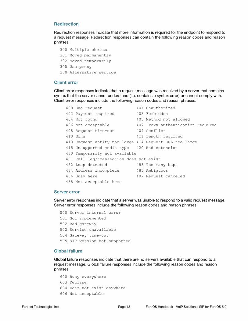
Redirection
Redirection responses indicate that more information is required for the endpoint to respond to
a request message. Redirection responses can contain the following reason codes and reason
phrases:
300 Multiple choices 301 Moved permanently 302 Moved temporarily305 Use proxy380 Alternative service
Client error
Client error responses indicate that a request message was received by a server that contains
syntax that the server cannot understand (i.e. contains a syntax error) or cannot comply with.
Client error responses include the following reason codes and reason phrases:
400 Bad request 401 Unauthorized 402 Payment required 403 Forbidden 404 Not found 405 Method not allowed406 Not acceptable 407 Proxy authentication required 408 Request time-out 409 Conflict 410 Gone 411 Length required413 Request entity too large 414 Request-URL too large 415 Unsupported media type 420 Bad extension480 Temporarily not available481 Call leg/transaction does not exist482 Loop detected 483 Too many hops 484 Address incomplete 485 Ambiguous 486 Busy here 487 Request canceled488 Not acceptable here
Server error
Server error responses indicate that a server was unable to respond to a valid request message.
Server error responses include the following reason codes and reason phrases:
500 Server internal error 501 Not implemented 502 Bad gateway502 Service unavailable 504 Gateway time-out 505 SIP version not supported
Global failure
Global failure responses indicate that there are no servers available that can respond to a
request message. Global failure responses include the following reason codes and reason
phrases:
600 Busy everywhere 603 Decline 604 Does not exist anywhere606 Not acceptable
Fortinet Technologies Inc. Page 18 FortiOS Handbook - VoIP Solutions: SIP for FortiOS 5.0
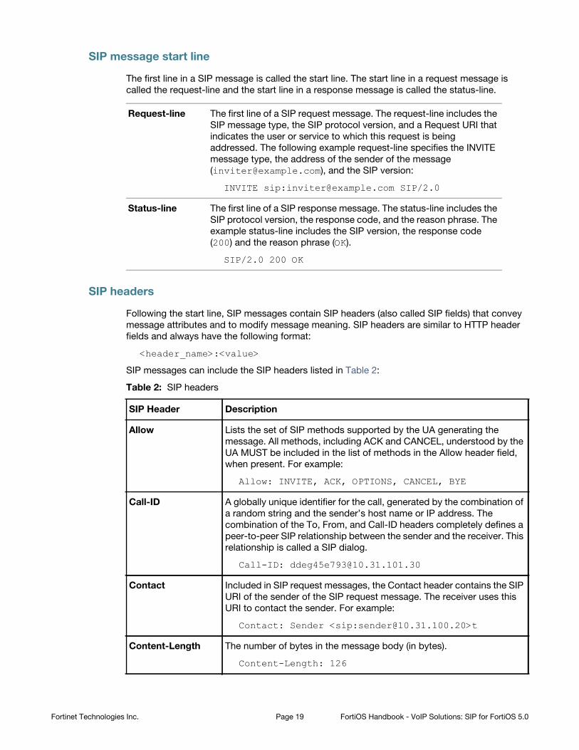
SIP message start line
The first line in a SIP message is called the start line. The start line in a request message is
called the request-line and the start line in a response message is called the status-line.
Request-line The first line of a SIP request message. The request-line includes the
SIP message type, the SIP protocol version, and a Request URI that
indicates the user or service to which this request is being
addressed. The following example request-line specifies the INVITE
message type, the address of the sender of the message
([email protected]), and the SIP version:
Status-line The first line of a SIP response message. The status-line includes the
SIP protocol version, the response code, and the reason phrase. The
example status-line includes the SIP version, the response code
(200) and the reason phrase (OK).
SIP headers
Following the start line, SIP messages contain SIP headers (also called SIP fields) that convey
message attributes and to modify message meaning. SIP headers are similar to HTTP header
fields and always have the following format:
<header_name>:<value>
SIP messages can include the SIP headers listed in Table 2:
INVITE sip:[email protected] SIP/2.0
SIP/2.0 200 OK
Table 2: SIP headers
SIP Header Description
Allow Lists the set of SIP methods supported by the UA generating the
message. All methods, including ACK and CANCEL, understood by the
UA MUST be included in the list of methods in the Allow header field,
when present. For example:
Allow: INVITE, ACK, OPTIONS, CANCEL, BYE
Call-ID A globally unique identifier for the call, generated by the combination of
a random string and the sender’s host name or IP address. The
combination of the To, From, and Call-ID headers completely defines a
peer-to-peer SIP relationship between the sender and the receiver. This
relationship is called a SIP dialog.
Call-ID: [email protected]
Contact Included in SIP request messages, the Contact header contains the SIP
URI of the sender of the SIP request message. The receiver uses this
URI to contact the sender. For example:
Contact: Sender <sip:[email protected]>t
Content-Length The number of bytes in the message body (in bytes).
Content-Length: 126
Fortinet Technologies Inc. Page 19 FortiOS Handbook - VoIP Solutions: SIP for FortiOS 5.0
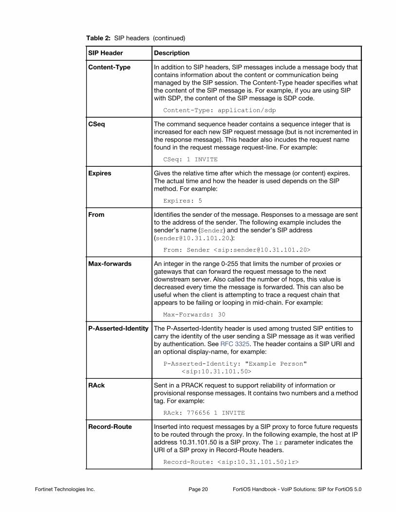
Content-Type In addition to SIP headers, SIP messages include a message body that
contains information about the content or communication being
managed by the SIP session. The Content-Type header specifies what
the content of the SIP message is. For example, if you are using SIP
with SDP, the content of the SIP message is SDP code.
Content-Type: application/sdp
CSeq The command sequence header contains a sequence integer that is
increased for each new SIP request message (but is not incremented in
the response message). This header also incudes the request name
found in the request message request-line. For example:
CSeq: 1 INVITE
Expires Gives the relative time after which the message (or content) expires.
The actual time and how the header is used depends on the SIP
method. For example:
Expires: 5
From Identifies the sender of the message. Responses to a message are sent
to the address of the sender. The following example includes the
sender’s name (Sender) and the sender’s SIP address
From: Sender <sip:[email protected]>
Max-forwards An integer in the range 0-255 that limits the number of proxies or
gateways that can forward the request message to the next
downstream server. Also called the number of hops, this value is
decreased every time the message is forwarded. This can also be
useful when the client is attempting to trace a request chain that
appears to be failing or looping in mid-chain. For example:
Max-Forwards: 30
P-Asserted-Identity The P-Asserted-Identity header is used among trusted SIP entities to
carry the identity of the user sending a SIP message as it was verified
by authentication. See RFC 3325. The header contains a SIP URI and
an optional display-name, for example:
P-Asserted-Identity: "Example Person" <sip:10.31.101.50>
RAck Sent in a PRACK request to support reliability of information or
provisional response messages. It contains two numbers and a method
tag. For example:
RAck: 776656 1 INVITE
Record-Route Inserted into request messages by a SIP proxy to force future requests
to be routed through the proxy. In the following example, the host at IP
address 10.31.101.50 is a SIP proxy. The lr parameter indicates the
URI of a SIP proxy in Record-Route headers.
Record-Route: <sip:10.31.101.50;lr>
Table 2: SIP headers (continued)
SIP Header Description
Fortinet Technologies Inc. Page 20 FortiOS Handbook - VoIP Solutions: SIP for FortiOS 5.0
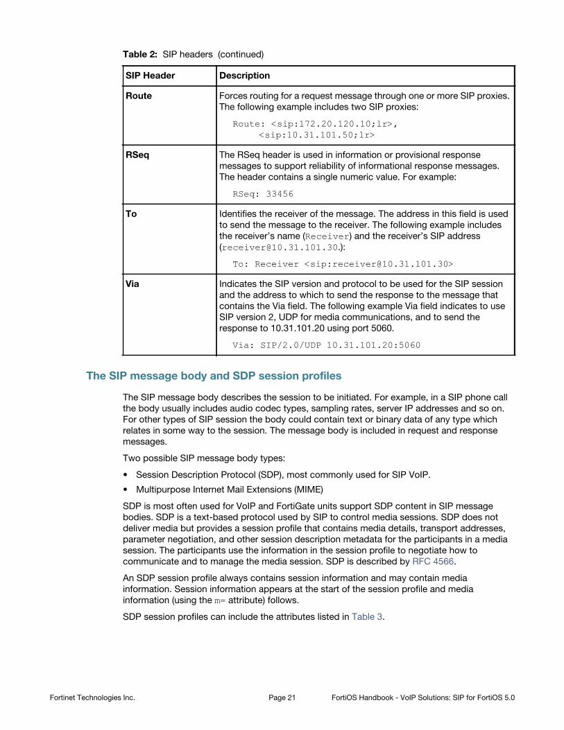
The SIP message body and SDP session profiles
The SIP message body describes the session to be initiated. For example, in a SIP phone call
the body usually includes audio codec types, sampling rates, server IP addresses and so on.
For other types of SIP session the body could contain text or binary data of any type which
relates in some way to the session. The message body is included in request and response
messages.
Two possible SIP message body types:
• Session Description Protocol (SDP), most commonly used for SIP VoIP.
• Multipurpose Internet Mail Extensions (MIME)
SDP is most often used for VoIP and FortiGate units support SDP content in SIP message
bodies. SDP is a text-based protocol used by SIP to control media sessions. SDP does not
deliver media but provides a session profile that contains media details, transport addresses,
parameter negotiation, and other session description metadata for the participants in a media
session. The participants use the information in the session profile to negotiate how to
communicate and to manage the media session. SDP is described by RFC 4566.
An SDP session profile always contains session information and may contain media
information. Session information appears at the start of the session profile and media
information (using the m= attribute) follows.
SDP session profiles can include the attributes listed in Table 3.
Route Forces routing for a request message through one or more SIP proxies.
The following example includes two SIP proxies:
Route: <sip:172.20.120.10;lr>, <sip:10.31.101.50;lr>
RSeq The RSeq header is used in information or provisional response
messages to support reliability of informational response messages.
The header contains a single numeric value. For example:
RSeq: 33456
To Identifies the receiver of the message. The address in this field is used
to send the message to the receiver. The following example includes
the receiver’s name (Receiver) and the receiver’s SIP address
To: Receiver <sip:[email protected]>
Via Indicates the SIP version and protocol to be used for the SIP session
and the address to which to send the response to the message that
contains the Via field. The following example Via field indicates to use
SIP version 2, UDP for media communications, and to send the
response to 10.31.101.20 using port 5060.
Via: SIP/2.0/UDP 10.31.101.20:5060
Table 2: SIP headers (continued)
SIP Header Description
Fortinet Technologies Inc. Page 21 FortiOS Handbook - VoIP Solutions: SIP for FortiOS 5.0
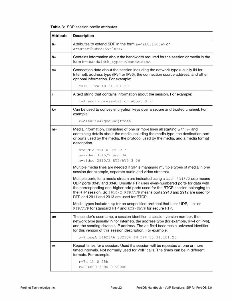
Table 3: SDP session profile attributes
Attribute Description
a= Attributes to extend SDP in the form a=<attribute> or
a=<attribute>:<value>.
b= Contains information about the bandwidth required for the session or media in the
form b=<bandwidth_type>:<bandwidth>.
c= Connection data about the session including the network type (usually IN for
Internet), address type (IPv4 or IPv6), the connection source address, and other
optional information. For example:
c=IN IPv4 10.31.101.20
i= A text string that contains information about the session. For example:
i=A audio presentation about SIP
k= Can be used to convey encryption keys over a secure and trusted channel. For
example:
k=clear:444gdduudjffdee
m= Media information, consisting of one or more lines all starting with m= and
containing details about the media including the media type, the destination port
or ports used by the media, the protocol used by the media, and a media format
description.
m=audio 49170 RTP 0 3m-video 3345/2 udp 34m-video 2910/2 RTP/AVP 3 56
Multiple media lines are needed if SIP is managing multiple types of media in one
session (for example, separate audio and video streams).
Multiple ports for a media stream are indicated using a slash. 3345/2 udp means
UDP ports 3345 and 3346. Usually RTP uses even-numbered ports for data with
the corresponding one-higher odd ports used for the RTCP session belonging to
the RTP session. So 2910/2 RTP/AVP means ports 2910 and 2912 are used for
RTP and 2911 and 2913 are used for RTCP.
Media types include udp for an unspecified protocol that uses UDP, RTP or
RTP/AVP for standard RTP and RTP/SAVP for secure RTP.
o= The sender’s username, a session identifier, a session version number, the
network type (usually IN for Internet), the address type (for example, IPv4 or IPv6),
and the sending device’s IP address. The o= field becomes a universal identifier
for this version of this session description. For example:
o=PhoneA 5462346 332134 IN IP4 10.31.101.20
r= Repeat times for a session. Used if a session will be repeated at one or more
timed intervals. Not normally used for VoIP calls. The times can be in different
formats. For example.
r=7d 1h 0 25hr=604800 3600 0 90000
Fortinet Technologies Inc. Page 22 FortiOS Handbook - VoIP Solutions: SIP for FortiOS 5.0
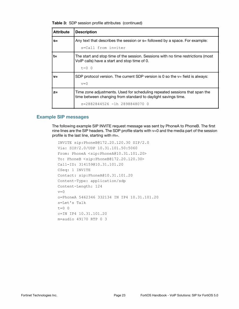
Example SIP messages
The following example SIP INVITE request message was sent by PhoneA to PhoneB. The first
nine lines are the SIP headers. The SDP profile starts with v=0 and the media part of the session
profile is the last line, starting with m=.
INVITE sip:[email protected] SIP/2.0Via: SIP/2.0/UDP 10.31.101.50:5060From: PhoneA <sip:[email protected]>To: PhoneB <sip:[email protected]>Call-ID: [email protected]: 1 INVITEContact: sip:[email protected]: application/sdpContent-Length: 124v=0o=PhoneA 5462346 332134 IN IP4 10.31.101.20s=Let's Talkt=0 0c=IN IP4 10.31.101.20m=audio 49170 RTP 0 3
s= Any text that describes the session or s= followed by a space. For example:
s=Call from inviter
t= The start and stop time of the session. Sessions with no time restrictions (most
VoIP calls) have a start and stop time of 0.
t=0 0
v= SDP protocol version. The current SDP version is 0 so the v= field is always:
v=0
z= Time zone adjustments. Used for scheduling repeated sessions that span the
time between changing from standard to daylight savings time.
z=2882844526 -1h 2898848070 0
Table 3: SDP session profile attributes (continued)
Attribute Description
Fortinet Technologies Inc. Page 23 FortiOS Handbook - VoIP Solutions: SIP for FortiOS 5.0
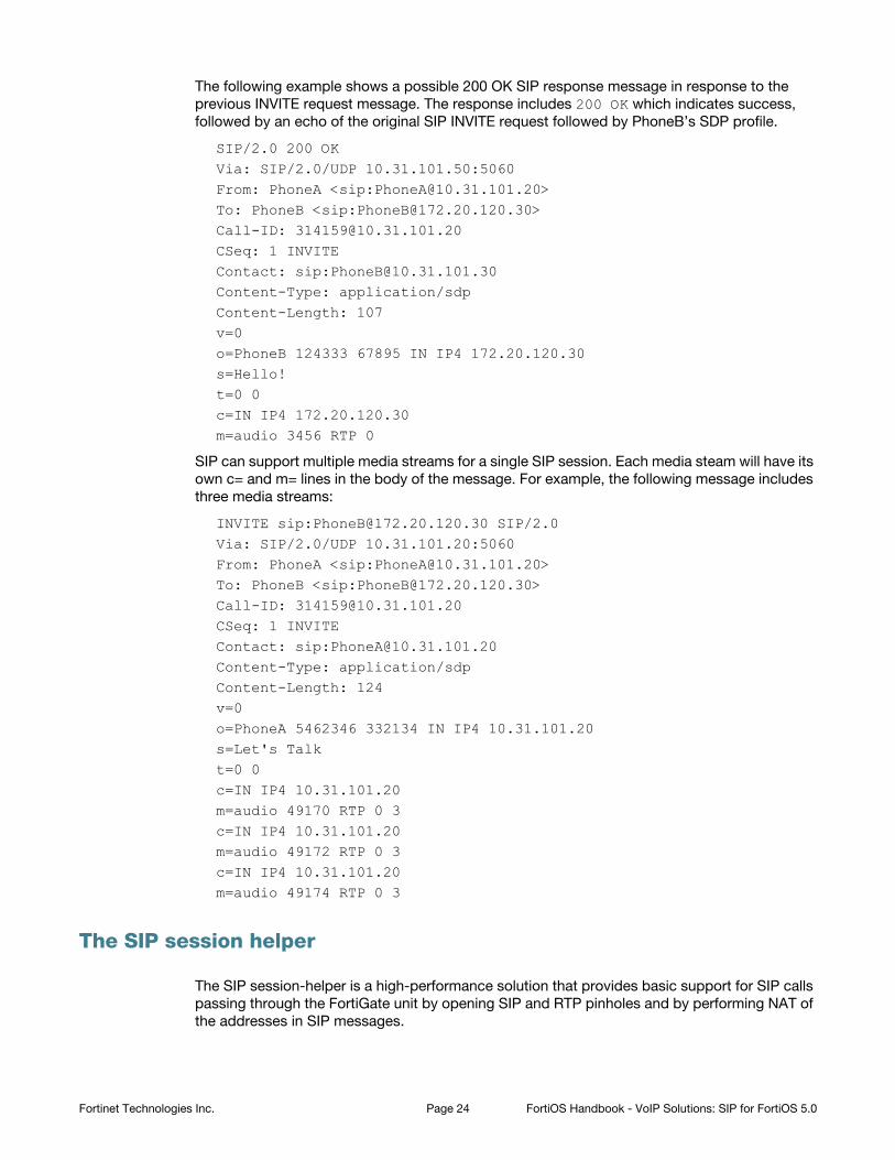
The following example shows a possible 200 OK SIP response message in response to the
previous INVITE request message. The response includes 200 OK which indicates success,
followed by an echo of the original SIP INVITE request followed by PhoneB’s SDP profile.
SIP/2.0 200 OKVia: SIP/2.0/UDP 10.31.101.50:5060From: PhoneA <sip:[email protected]>To: PhoneB <sip:[email protected]>Call-ID: [email protected]: 1 INVITEContact: sip:[email protected]: application/sdpContent-Length: 107 v=0o=PhoneB 124333 67895 IN IP4 172.20.120.30s=Hello!t=0 0c=IN IP4 172.20.120.30m=audio 3456 RTP 0
SIP can support multiple media streams for a single SIP session. Each media steam will have its
own c= and m= lines in the body of the message. For example, the following message includes
three media streams:
INVITE sip:[email protected] SIP/2.0Via: SIP/2.0/UDP 10.31.101.20:5060From: PhoneA <sip:[email protected]>To: PhoneB <sip:[email protected]>Call-ID: [email protected]: 1 INVITEContact: sip:[email protected]: application/sdpContent-Length: 124v=0o=PhoneA 5462346 332134 IN IP4 10.31.101.20s=Let's Talkt=0 0c=IN IP4 10.31.101.20m=audio 49170 RTP 0 3c=IN IP4 10.31.101.20m=audio 49172 RTP 0 3c=IN IP4 10.31.101.20m=audio 49174 RTP 0 3
The SIP session helper
The SIP session-helper is a high-performance solution that provides basic support for SIP calls
passing through the FortiGate unit by opening SIP and RTP pinholes and by performing NAT of
the addresses in SIP messages.
Fortinet Technologies Inc. Page 24 FortiOS Handbook - VoIP Solutions: SIP for FortiOS 5.0
The SIP session helper:
• Understands SIP dialog messages.
• Keeps the states of the SIP transactions between SIP UAs and SIP servers.
• Translates SIP header and SDP information to account for NAT operations performed by the
FortiGate unit.
• Opens up and closes dynamic SIP pinholes for SIP signalling traffic.
• Opens up and closes dynamic RTP and RTSP pinholes for RTP and RTSP media traffic.
• Provides basic SIP security as an access control device.
• Uses the intrusion protection (IPS) engine to perform basic SIP protocol checks.
SIP session helper configuration overview
The SIP session helper is enabled by default and set to listen for SIP traffic on TCP or UDP port
5060. SIP sessions using port 5060 accepted by a security policy that does not include a VoIP
profile are processed by the SIP session helper.
You can enable and disable the SIP session helper, change the TCP or UDP port that the
session helper listens on for SIP traffic, and enable or disable SIP NAT tracing. If the FortiGate
unit is operating with multiple VDOMs, each VDOM can have a different SIP session helper
configuration.
To have the SIP session helper process SIP sessions you need to add a security policy that
accepts SIP sessions on the configured SIP UDP or TCP ports. The security policies can have
service set to ANY, or to the SIP pre-defined firewall service, or a custom firewall service. The
SIP pre-defined firewall service restricts the security policy to only accepting sessions on UDP
port 5060.
If NAT is enabled for security policies that accept SIP traffic, the SIP session helper translates
addresses in SIP headers and in the RDP profile and opens up pinholes as required for the SIP
traffic. This includes security policies that perform source NAT and security policies that contain
virtual IPs that perform destination NAT and port forwarding. No special SIP configuration is
required for this address translation to occur, it is all handled automatically by the SIP session
helper according to the NAT configuration of the security policy that accepts the SIP session.
To use the SIP session helper you must not add a VoIP profile to the security policy. If you add a
VoIP profile, SIP traffic bypasses the SIP session helper and is processed by the SIP ALG.
Disabling and enable the SIP session helper
You can use the following steps to disable the SIP session helper. You might want to disable the
SIP session helper if you don’t want the FortiGate unit to apply NAT or other SIP session help
features to SIP traffic. With the SIP session helper disabled, the FortiGate unit can still accept
SIP sessions if they are allowed by a security policy, but the FortiGate unit will not be able to
open pinholes or NAT the addresses in the SIP messages.
In most cases you would want to use the SIP ALG since the SIP session helper provides limited
functionality. However, the SIP session helper is available and can be useful for
high-performance solutions where a high level of SIP security is not a requirement.
Fortinet Technologies Inc. Page 25 FortiOS Handbook - VoIP Solutions: SIP for FortiOS 5.0
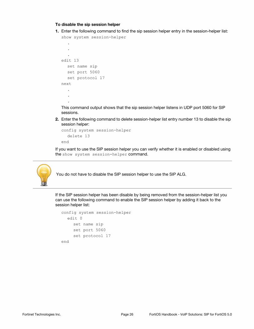
To disable the sip session helper
1. Enter the following command to find the sip session helper entry in the session-helper list:
show system session-helper...
edit 13set name sipset port 5060set protocol 17
next...
This command output shows that the sip session helper listens in UDP port 5060 for SIP
sessions.
2. Enter the following command to delete session-helper list entry number 13 to disable the sip
session helper:
config system session-helperdelete 13
end
If you want to use the SIP session helper you can verify whether it is enabled or disabled using
the show system session-helper command.
If the SIP session helper has been disable by being removed from the session-helper list you
can use the following command to enable the SIP session helper by adding it back to the
session helper list:
config system session-helperedit 0
set name sipset port 5060set protocol 17
end
You do not have to disable the SIP session helper to use the SIP ALG.
Fortinet Technologies Inc. Page 26 FortiOS Handbook - VoIP Solutions: SIP for FortiOS 5.0
Changing the port numbers that the SIP session helper listens on
You can use the following command to change the port number that the SIP session helper
listens on for SIP traffic to 5064. The SIP session helper listens on the same port number for
UDP and TCP SIP sessions. In this example, the SIP session helper is session helper 13:
config system session-helperedit 13
set port 5064end
Your FortiGate unit may use a different session helper number for SIP. Enter the following
command to view the session helpers:
show system session-helper...edit 13
set name sipset port 5060set protocol 17
end...
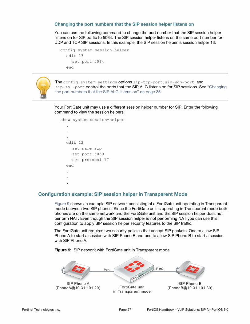
Configuration example: SIP session helper in Transparent Mode
Figure 9 shows an example SIP network consisting of a FortiGate unit operating in Transparent
mode between two SIP phones. Since the FortiGate unit is operating in Transparent mode both
phones are on the same network and the FortiGate unit and the SIP session helper does not
perform NAT. Even though the SIP session helper is not performing NAT you can use this
configuration to apply SIP session helper security features to the SIP traffic.
The FortiGate unit requires two security policies that accept SIP packets. One to allow SIP
Phone A to start a session with SIP Phone B and one to allow SIP Phone B to start a session
with SIP Phone A.
Figure 9: SIP network with FortiGate unit in Transparent mode
The config system settings options sip-tcp-port, sip-udp-port, and
sip-ssl-port control the ports that the SIP ALG listens on for SIP sessions. See “Changing
the port numbers that the SIP ALG listens on” on page 35.
FortiGate unitin Transparent mode
SIP Phone A([email protected])
SIP Phone B([email protected])
Port1 Port21 Po
Fortinet Technologies Inc. Page 27 FortiOS Handbook - VoIP Solutions: SIP for FortiOS 5.0
General configuration steps
The following general configuration steps are required for this SIP configuration that uses the
SIP session helper. This example includes security policies that specifically allow SIP sessions
using UDP port 5060 from Phone A to Phone B and from Phone B to Phone A. In most cases
you would have more than two phones so would use more general security policies. Also, you
can set the firewall service to ANY to allow traffic other than SIP on UDP port 5060.
1. Add firewall addresses for Phone A and Phone B.
2. Add a security policy that accepts SIP sessions initiated by Phone A.
3. Add a security policy that accepts SIP sessions initiated by Phone B.
Configuration steps - web-based manager
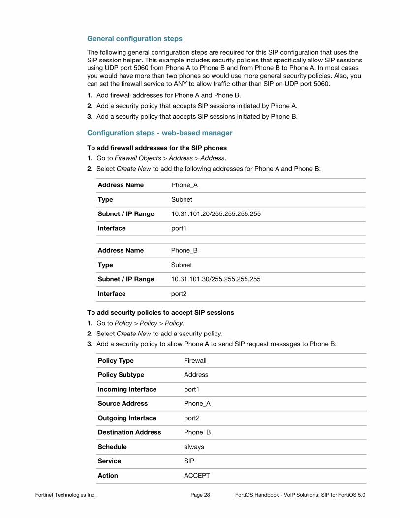
To add firewall addresses for the SIP phones
1. Go to Firewall Objects > Address > Address.
2. Select Create New to add the following addresses for Phone A and Phone B:
To add security policies to accept SIP sessions
1. Go to Policy > Policy > Policy.
2. Select Create New to add a security policy.
3. Add a security policy to allow Phone A to send SIP request messages to Phone B:
Address Name Phone_A
Type Subnet
Subnet / IP Range 10.31.101.20/255.255.255.255
Interface port1
Address Name Phone_B
Type Subnet
Subnet / IP Range 10.31.101.30/255.255.255.255
Interface port2
Policy Type Firewall
Policy Subtype Address
Incoming Interface port1
Source Address Phone_A
Outgoing Interface port2
Destination Address Phone_B
Schedule always
Service SIP
Action ACCEPT
Fortinet Technologies Inc. Page 28 FortiOS Handbook - VoIP Solutions: SIP for FortiOS 5.0

4. Select OK.
5. Add a security policy to allow Phone B to send SIP request messages to Phone A:
6. Select OK.
Configuration steps - CLI
To add firewall addresses for Phone A and Phone B and security policies to accept SIP
sessions
1. Enter the following command to add firewall addresses for Phone A and Phone B.
config firewall addressedit Phone_A
set associated interface port1set type ipmaskset subnet 10.31.101.20 255.255.255.255
nextedit Phone_B
set associated interface port2set type ipmaskset subnet 10.31.101.30 255.255.255.255
end
Policy Type Firewall
Policy Subtype Address
Incoming Interface port2
Source Address Phone_B
Outgoing Interface port1
Destination Address Phone_A
Schedule always
Service SIP
Action ACCEPT
Fortinet Technologies Inc. Page 29 FortiOS Handbook - VoIP Solutions: SIP for FortiOS 5.0
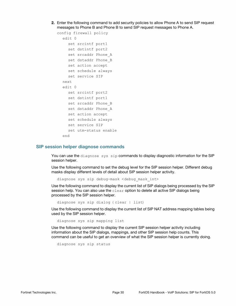
2. Enter the following command to add security policies to allow Phone A to send SIP request
messages to Phone B and Phone B to send SIP request messages to Phone A.
config firewall policyedit 0
set srcintf port1set dstintf port2set srcaddr Phone_Aset dstaddr Phone_Bset action acceptset schedule alwaysset service SIP
nextedit 0
set srcintf port2set dstintf port1set srcaddr Phone_Bset dstaddr Phone_Aset action acceptset schedule alwaysset service SIPset utm-status enable
end
SIP session helper diagnose commands
You can use the diagnose sys sip commands to display diagnostic information for the SIP
session helper.
Use the following command to set the debug level for the SIP session helper. Different debug
masks display different levels of detail about SIP session helper activity.
diagnose sys sip debug-mask <debug_mask_int>
Use the following command to display the current list of SIP dialogs being processed by the SIP
session help. You can also use the clear option to delete all active SIP dialogs being
processed by the SIP session helper.
diagnose sys sip dialog {clear | list}
Use the following command to display the current list of SIP NAT address mapping tables being
used by the SIP session helper.
diagnose sys sip mapping list
Use the following command to display the current SIP session helper activity including
information about the SIP dialogs, mappings, and other SIP session help counts. This
command can be useful to get an overview of what the SIP session helper is currently doing.
diagnose sys sip status
Fortinet Technologies Inc. Page 30 FortiOS Handbook - VoIP Solutions: SIP for FortiOS 5.0
The SIP ALG
In most cases you should use the SIP Application Layer Gateway (ALG) for processing SIP
sessions. The SIP ALG provides the same basic SIP support as the SIP session helper.
Additionally, the SIP ALG provides a wide range of features that protect your network from SIP
attacks, can apply rate limiting to SIP sessions, can check the syntax of SIP and SDP content of
SIP messages, and provide detailed logging and reporting of SIP activity.
You apply the SIP ALG to SIP traffic by adding a VoIP profile with SIP enabled to a security
policy that accepts SIP traffic. The SIP session helper is automatically bypassed by traffic
accepted by a security policy that includes a VoIP profile.
As shown in Figure 10, the FortiGate SIP ALG intercepts SIP packets after they have been
routed by the routing module, accepted by a security policy and passed through DoS and IPS
Sensors (if DoS and IPS are enabled). The ALG raises SIP packets to the application layer,
analyzes the SIP and SDP addressing information in the SIP messages, makes adjustments (for
example, NAT) to this addressing if required, and then sends the packets out the egress
interface to their destination.
The SIP ALG provides:
• All the same features as the SIP session help including NAT and SIP and RTP Pinholes.
• In addition for the ALG you can enable or disable RTP pinholing, SIP register pinholing and
SIP contact pinholing. In a signalling only environment where the RTP stream bypasses the
FortiGate unit, you can disable RTP pinholing to improve performance.
• SIP TCP and UDP support
• SIP Message order checking
• Configurable Header line length maximums
Fortinet Technologies Inc. Page 31 FortiOS Handbook - VoIP Solutions: SIP for FortiOS 5.0
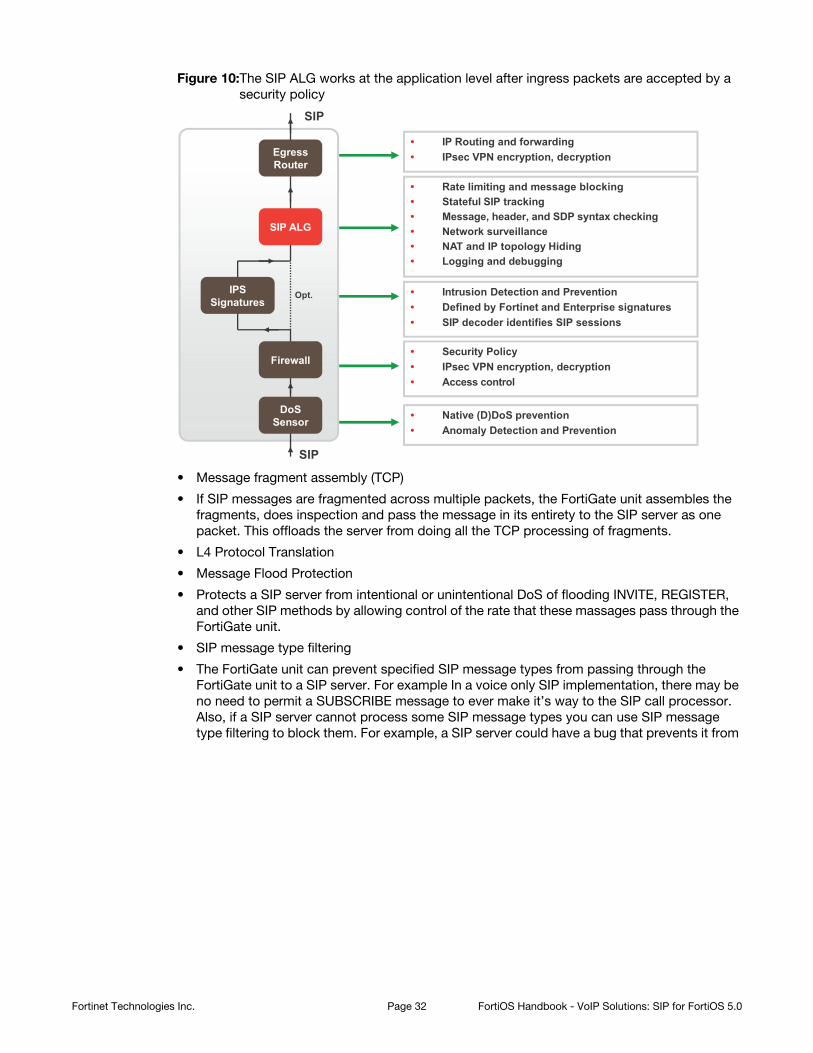
Figure 10:The SIP ALG works at the application level after ingress packets are accepted by a
security policy
• Message fragment assembly (TCP)
• If SIP messages are fragmented across multiple packets, the FortiGate unit assembles the
fragments, does inspection and pass the message in its entirety to the SIP server as one
packet. This offloads the server from doing all the TCP processing of fragments.
• L4 Protocol Translation
• Message Flood Protection
• Protects a SIP server from intentional or unintentional DoS of flooding INVITE, REGISTER,
and other SIP methods by allowing control of the rate that these massages pass through the
FortiGate unit.
• SIP message type filtering
• The FortiGate unit can prevent specified SIP message types from passing through the
FortiGate unit to a SIP server. For example In a voice only SIP implementation, there may be
no need to permit a SUBSCRIBE message to ever make it’s way to the SIP call processor.
Also, if a SIP server cannot process some SIP message types you can use SIP message
type filtering to block them. For example, a SIP server could have a bug that prevents it from
Opt.
SIP
SIP
• Rate limiting and message blocking• Stateful SIP tracking• Message, header, and SDP syntax checking• Network surveillance • NAT and IP topology Hiding• Logging and debugging
• Native (D)DoS prevention• Anomaly Detection and Prevention
• Security Policy• IPsec VPN encryption, decryption• Access control
• IP Routing and forwarding• IPsec VPN encryption, decryption
• Intrusion Detection and Prevention• Defined by Fortinet and Enterprise signatures• SIP decoder identifies SIP sessions
Firewall
DoS Sensor
IPS Signatures
SIP ALG
Egress Router
Fortinet Technologies Inc. Page 32 FortiOS Handbook - VoIP Solutions: SIP for FortiOS 5.0
processing certain SIP messages. In this case you can temporarily block these message
types until problem with the SIP server has been fixed.
• SIP statistics and logging
• SIP over IPv6
• SIP over SSL/TLS
• Deep SIP message syntax checking (also called deep SIP header inspection or SIP fuzzing
protection). Prevents attacks that use malformed SIP messages. Can check many SIP
headers and SDP statements. Configurable bypass and modification options.
• Hosted NAT traversal, Resolves IP address issue in SIP and SDP lines due to NAT-PT in far
end firewall. Important feature for VoIP access networks.
• SIP High Availability (HA), including active-passive clustering and session pickup (session
failover) for SIP sessions.
• Geographical Redundancy. In an HA configuration, if the active SIP server fails (missing SIP
heartbeat messages or SIP traffic) SIP sessions can be redirected to a secondary SIP server
in another location.
• SIP per request method message rate limitation with configurable threshold for SIP message
rates per request method. Protects SIP servers from SIP overload and DoS attacks.
• RTP Bypass, Supports configurations with and without RTP pinholing. May inspect and
protect SIP signaling only.
• SIP NAT with IP address conservation. Performs SIP and RTP aware IP Network Address
translation. Preserves the lost IP address information in the SDP profile i= line for later
processing/debugging in the SIP server. See “NAT with IP address conservation” on
page 63.
• IP topology hiding
• The IP topology of a network can be hidden through NAT and NAPT manipulation of IP and
SIP level addressing. For example, see “SIP NAT configuration example: destination address
translation (destination NAT)” on page 58.
• SIP inspection without address translation
• The SIP ALG inspects SIP messages but addresses in the messages are not translated. This
feature can be applied to a FortiGate unit operating in Transparent mode or in NAT/Route
mode. In Transparent mode you add normal Transparent mode security policies that enable
the SIP ALG and include a VoIP profile that causes the SIP ALG to inspect SIP traffic as
required. For an example configuration, see “Configuration example: SIP in Transparent
Mode” on page 41.
• For a FortiGate unit operating in NAT/Route mode, if SIP traffic can pass between different
networks without requiring NAT because is supported by the routing configuration, you can
add security policies that accept SIP traffic without enabling NAT. In the VoIP profile you can
configure the SIP ALG to inspect SIP traffic as required.
SIP ALG configuration overview
To apply the SIP ALG, you add a SIP VoIP profile to a security policy that accepts SIP sessions.
All SIP sessions accepted by the security policy will be processed by the SIP ALG using the
settings in the VoIP profile. The VoIP profile contains settings that are applied to SIP, Session
Initiation Protocol for Instant Messaging and Presence Leveraging Extensions (SIMPLE) and
Skinny Call Control Protocol (SCCP) sessions. You configure SIP and SCCP settings separately.
SIP settings also apply to SIMPLE sessions.
Fortinet Technologies Inc. Page 33 FortiOS Handbook - VoIP Solutions: SIP for FortiOS 5.0
Enabling VoIP support on the web-based manager
Before you begin adding VoIP profiles to security policies you may have to enable VoIP support
on the web-based manager. To do this, on the web-based manager go to System > Admin >
Settings and make sure that the VoIP checkbox is selected.
From the CLI you can also enter the following command enable VoIP support on the GUI:
config system globalset gui-voip-profile enable
end
VoIP profiles
To add a new VoIP profile from the web-based manager go to UTM Security Profiles > VoIP >
Profile and select Create New.
For SIP, from the web-based manager you can configure the VoIP profile to limit the number of
SIP REGISTER and INVITE requests and enable logging of SIP sessions and SIP violations.
Many additional options for configuring how the ALG processes SIP sessions are available from
the CLI.
For SCCP you can limit the call setup time. Additional SCCP options are available from the CLI.
Use the following command to add a VoIP profile named VoIP_Pro_1 from the CLI:
config voip profileedit VoIP_Pro_1
end
FortiGate units include two pre-defined VoIP profiles. On the web-based manager these profiles
look identical. However, the CLI-only settings result in the following functionality.
default The most commonly used VoIP profile. This profile enables both SIP and SCCP and
places the minimum restrictions on what calls will be allowed to negotiate. This
profile allows normal SCCP, SIP and RTP sessions and enables the following
security settings:
strict This profile is available for users who want to validate SIP messages and to only
allow SIP sessions that are compliant with RFC 3261. In addition to the settings in
the default VoIP profile, the strict profile sets all SIP deep message inspection
header checking to block and drop SIP messages that contain malformed SIP or
SDP lines that can be detected by the ALG. For more information about SIP deep
header inspection, see “Deep SIP message inspection” on page 77.
• block-long-lines to block SIP messages with lines that exceed maximum
line lengths.
• block-unknown to block unrecognized SIP request messages.
• log-violations to write log messages that record SIP violations.
• log-call-summary to write log messages that record SIP call progress (similar
to DLP archiving).
• nat-trace (see “NAT with IP address conservation” on page 63).
• contact-fixup perform NAT on the IP addresses and port numbers in SIP
headers in SIP CONTACT messages even if they don’t match the session’s IP
address and port numbers.
Fortinet Technologies Inc. Page 34 FortiOS Handbook - VoIP Solutions: SIP for FortiOS 5.0
Neither of the default profiles applies SIP rate limiting or message blocking. To apply more ALG
features to SIP sessions you can clone (copy) the pre-defined VoIP profiles and make your own
modifications to them. For example, to clone the default profile and configure the limit for SIP
NOTIFY request messages to 1000 messages per second per security policy and block SIP
INFO request messages.
config voip profileclone default to my_voip_proedit my_voip_pro
config sipset notify-rate 1000set block-info enable
endend
Changing the port numbers that the SIP ALG listens on
Most SIP configurations use TCP or UDP port 5060 for SIP sessions and port 5061 for SIP SSL
sessions. If your SIP network uses different ports for SIP sessions you can use the following
command to configure the SIP ALG to listen on a different TCP, UDP, or SSL ports. For example,
to change the TCP port to 5064, the UDP port to 5065, and the SSL port to 5066.
config system settingsset sip-tcp-port 5064set sip-udp-port 5065set sip-ssl-port 5066
end
Disabling the SIP ALG in a VoIP profile
SIP is enabled by default in a VoIP profile. Usually you would want SIP to be enabled in a VoIP
profile. But in some cases if you are just using the VoIP profile for SCCP you can use the
following command to disable SIP in a VoIP profile.
config voip profileedit VoIP_Pro_2
config sipset status disable
endend
SIP ALG get and diagnose commands
You can use the following commands to display diagnostic information for the SIP ALG.
Use the following command to list all active SIP calls being processed by the SIP ALG. You can
also use the clear option to delete all active SIP calls being processed by the SIP ALG.
diagnose sys sip-proxy calls {clear | list}
Use the following commands to use filters to display specific information about the SIP ALG
and the session that it is processing.
diagnose sys sip-proxy filter <filter_options>diagnose sys sip-proxy log-filter <filter_options>
Use the following command to display the active SIP rate limiting meters and their current
settings.
diagnose sys sip-proxy meters list
Fortinet Technologies Inc. Page 35 FortiOS Handbook - VoIP Solutions: SIP for FortiOS 5.0
Use the following command to display status information about the SIP sessions being
processed by the SIP ALG. You can also clear all SIP ALG statistics.
diagnose sys sip-proxy stats {clear | list}
Conflicts between the SIP ALG and the session helper
Even if the SIP session helper is enabled, if a security policy with a VoIP profile that has SIP
enabled accepts a SIP session on the TCP or UDP port that the SIP ALG listens on the ALG is
used. You don’t need to turn off the session helper to use the ALG.
You may find that the session helper is being used for some SIP sessions even when you only
want to use the ALG. This happens if a policy that does not include a VoIP profile is accepting
SIP sessions. The VoIP profile could have been left out of the policy by mistake or the wrong
policy could be accepting SIP sessions.
Consider a configuration with a SIP server on a private network that is contacted by SIP phones
on the Internet and on the private network (similar to the configuration in Figure 6 on page 13).
The FortiGate unit that provides NAT between the private network and the Internet requires a
security policy with a firewall virtual IP that allows the SIP phones on the Internet to contact the
SIP server. The FortiGate unit also requires outgoing security policies to allow the SIP phones
and the SIP server to contact the SIP phones on the Internet.
If a VoIP profile is not added to one of the outgoing security policies the SIP sessions accepted
by that policy will be processed by the SIP session helper instead of the SIP ALG. Also, its
possible that some of the SIP sessions could be accepted by a general outgoing policy instead
of the policy intended for SIP traffic. You can fix the first problem by adding a VoIP profile to the
policy. You can fix the second problem by reviewing the security policy order and source and
destination addresses in the security policies and determining if there is a conflict between
these and the IP addresses of the SIP server or SIP phones on the Internal network.
You can use diagnose sys sip commands to determine if the SIP session helper is
processing SIP sessions. For example, the following command displays the overall status of the
SIP sessions being processed by the SIP session helper:
diagnose sys sip statusdialogs: max=32768, used=0mappings: used=0dialog hash by ID: size=2048, used=0, depth=0dialog hash by RTP: size=2048, used=0, depth=0mapping hash: size=2048, used=0, depth=0count0: 0count1: 0count2: 0count3: 0count4: 0
This command output shows that the session helper is not processing SIP sessions because all
of the used and count fields are 0. If any of these fields contains non-zero values then the SIP
session helper may be processing SIP sessions.
The diagnose sys sip commands only display current status information. To see activity
the SIP session helper has to actually be processing SIP sessions when you enter the
command. For example, if the SIP session helper had been used for processing calls that
ended 5 minutes ago, the command output would show no SIP session helper activity.
Fortinet Technologies Inc. Page 36 FortiOS Handbook - VoIP Solutions: SIP for FortiOS 5.0
Also, you can check to see if some ALG-only features are not being applied to all SIP sessions.
For example, the VoIP usage widget on the FortiGate dashboard displays statistics for SIP and
SCCP calls processed by the ALG but not for calls processed by the session helper. So if you
see fewer calls than expected the session helper may be processing some of them.
Other logging and monitoring features such as log messages and DLP archiving are only
supported by the ALG.
Finally, you can check the policy usage and session information dashboard widgets to see if SIP
sessions are being accepted by the wrong security policies.
Stateful SIP tracking, call termination, and session inactivity timeout
The SIP ALG tracks SIP dialogs over their lifespan between the first INVITE message and the
Final 200 OK and ACK messages. For every SIP dialog, stateful SIP tracking reviews every SIP
message and makes adjustment to SIP tracking tables as required. These adjustments include
source and destination IP addresses, address translation, dialog expiration information, and
media stream port changes. Such changes can also result in dynamically opening and closing
pinholes. You can use the diagnose sys sip-proxy stats list and the diagnose sys sip-proxy filter command to view the SIP call data being tracked by the SIP ALG.
The SIP ALG uses the SIP Expires header line to time out a SIP dialog if the dialog is idle and a
Re-INVITE or UPDATE message is not received. The SIP ALG gets the Session-Expires value, if
present, from the 200 OK response to the INVITE message. If the SIP ALG receives an INVITE
before the session times out, all timeout values are reset to the settings in the new INVITE
message or to default values. As a precautionary measure, the SIP ALG uses hard timeout
values to set the maximum amount of time a call can exist. This ensures that the FortiGate unit
is protected if a call ends prematurely.
When a SIP dialog ends normally, the SIP ALG deletes the SIP call information and closes open
pinholes. A SIP call can also end abnormally due to an unexpected signaling or transport event
that cuts off the call. When a call ends abnormally the SIP messages to end the call may not be
sent or received. A call can end abnormally for the following reasons:
• Phones or servers crash during a call and a BYE message is not received.
• To attack a SIP system, a malicious user never send a BYE message.
• Poor implementations of SIP fail to process Record-Route messages and never send a BYE
message.
• Network failures prevent a BYE message from being received.
Any phone or server in a SIP call can cancel the call by sending a CANCEL message. When a
CANCEL message is received by the FortiGate unit, the SIP ALG closes open pinholes. Before
terminating the call, the ALG waits for the final 200 OK message.
The SIP ALG can be configured to terminate SIP calls if the SIP dialog message flow or the call
RTP (media) stream is interrupted and does not recover. You can use the following commands
to configure terminating inactive SIP sessions and to set timers or counters to control when the
call is terminated by the SIP ALG.
Fortinet Technologies Inc. Page 37 FortiOS Handbook - VoIP Solutions: SIP for FortiOS 5.0

Adding a media stream timeout for SIP calls
Use the following command in a VoIP profile to terminate SIP calls accepted by a security policy
containing the VoIP profile when the RTP media stream is idle for 100 seconds.
config voip profileedit VoIP_Pro_Name
config sipset call-keepalive 100
endend
You can adjust this setting between 1 and 10,080 seconds. The default call keepalive setting of
0 disables terminating a call if the media stream is interrupted. Set call keepalive higher if your
network has latency problems that could temporarily interrupt media streams. If you have
configured call keepalive and the FortiGate unit terminates calls unexpectedly you can increase
the call keepalive time to resolve the problem.
Call keep alive should be used with caution because enabling this feature results in extra
FortiGate CPU overhead and can cause delay/jitter for the VoIP call. Also, the FortiGate unit
terminates the call without sending SIP messages to end the call. And if the SIP endpoints send
SIP messages to terminate the call they will be blocked by the FortiGate unit if they are sent
after the FortiGate unit terminates the call.
Adding an idle dialog setting for SIP calls
Use the following command in a VoIP profile to terminate SIP calls when for a single security
policy, when the configured number of SIP calls (or dialogs) has stopped receiving SIP
messages or has not received legitimate SIP messages. Using this command you can configure
how many dialogs that have been accepted by a security policy that the VoIP profile is added to
become idle before the SIP ALG deletes the oldest ones. The following command sets the
maximum number of idle dialogs to 200:
config voip profileedit VoIP_Pro_Name
config sipset max-idle-dialogs 200
endend
Idle dialogs would usually be dialogs that have been interrupted because of errors or problems
or as the result of a SIP attack that opens a large number of SIP dialogs without closing them.
This command provides a way to remove these dialogs from the dialog table and recover
memory and resources being used by these open and idle dialogs.
You can adjust this setting between 1 and a very high number. The default maximum idle
dialogs setting of 0 disables this feature. Set maximum dialogs higher if your network has
latency problems that could temporarily interrupt SIP messaging. If you have configured max
idle dialogs and the FortiGate unit terminates calls unexpectedly you can increase the max idle
dialogs number to resolve the problem.
Changing how long to wait for call setup to complete
In some cases and some configurations your SIP system may experience delays during call
setup. If this happens, some SIP ALG timers may expire before call setup is complete and drop
the call. In some cases you may also want to reduce the amount of time the SIP ALG allows for
call setup to complete.
Fortinet Technologies Inc. Page 38 FortiOS Handbook - VoIP Solutions: SIP for FortiOS 5.0
You can use the provisional-invite-expiry-time SIP VoIP profile option to control how
long the SIP ALG waits for provisional INVITE messages before assuming that the call setup has
been interrupted and the SIP call should be dropped. The default value for this timer is 210
seconds. You can change it to between 10 and 3600 seconds.
Use the following command to change the expiry time to 100 seconds.
config voip profileedit Profile_name
config sipset provisional-invite-expiry-time 100
endend
SIP and RTP/RTCP
FortiGate units support the Real Time Protocol (RTP) application layer protocol for the VoIP call
audio stream. RTP uses dynamically assigned port numbers that can change during a call. SIP
control messages that start a call and that are sent during the call inform callers of the port
number to use and of port number changes during the call.
During a call, each RTP session will usually have a corresponding Real Time Control Protocol
(RTCP) session. By default, the RTCP session port number is one higher than the RTP port
number.
The RTP port number is included in the m= part of the SDP profile. In the example above, the
SIP INVITE message includes RTP port number is 49170 so the RTCP port number would be
49171. In the SIP response message the RTP port number is 3456 so the RTCP port number
would be 3457.
How the SIP ALG creates RTP pinholes
The SIP ALG requires the following information to create a pinhole. The SIP ALG finds this
information in SIP messages and some is provided by the SIP ALG:
Protocol UDP (Extracted from SIP messages by the SIP ALG.)
Source IP Any
Source port Any
Destination IP The SIP ALG extracts the destination IP address from the c= line in the
SDP profile. The c= line can appear in either the session or media part of
the SDP profile. The SIP ALG uses the IP address in the c= line of the
media part of the SDP profile first. If the media part does not contain a c=
line, the SIP ALG checks the c= line in the session part of the SDP profile.
If the session part of the profile doesn’t contain a c= line the packet is
dropped. Pinholes for RTP and RTCP sessions share the same destination
IP address.
Destination port The SIP ALG extracts the destination port number for RTP from the m=
field and adds 1 to this number to get the RTCP port number.
Lifetime The length of time during which the pinhole will be open. When the lifetime
ends, the SIP ALG removes the pinhole.
Fortinet Technologies Inc. Page 39 FortiOS Handbook - VoIP Solutions: SIP for FortiOS 5.0
The SIP ALG keeps RTP pinholes open as long as the SIP session is alive. When the associated
SIP session is terminated by the SIP ALG or the SIP phones or servers participating in the call,
the RTP pinhole is closed.
Figure 11 shows a simplified call setup sequence that shows how the SIP ALG opens pinholes.
Phone A and Phone B are installed on either side of a FortiGate unit operating in Transparent
mode. Phone A and Phone B are on the same subnet. The FortiGate unit includes a security
policy that accepts SIP sessions from port1 to port2 and from port2 to port1. The FortiGate unit
does not require an RTP security policy, just the SIP policy.
You can see from this diagram that the SDP profile in the INVITE request from Phone A indicates
that Phone A is expecting to receive a media stream sent to its IP address using port 4000 for
RTP and port 4001 for RTCP. The SIP ALG creates pinhole 1 to allow this media traffic to pass
through the FortiGate unit. Pinhole 1 is opened on the Port2 interface and will accept media
traffic sent from Phone B to Phone A.
When Phone B receives the INVITE request from Phone A, Phone B will know to send media
streams to Phone A using destination IP address 10.31.101.20 and ports 4000 and 4001. The
200 OK response sent from Phone B indicates that Phone B is expecting to receive a media
stream sent to its IP address using ports 8000 and 8001. The SIP ALG creates pinhole 2 to allow
this media traffic to pass through the FortiGate unit. Pinhole 2 is opened on the Port1 interface
and will accept media traffic sent from Phone A to Phone B.
Fortinet Technologies Inc. Page 40 FortiOS Handbook - VoIP Solutions: SIP for FortiOS 5.0
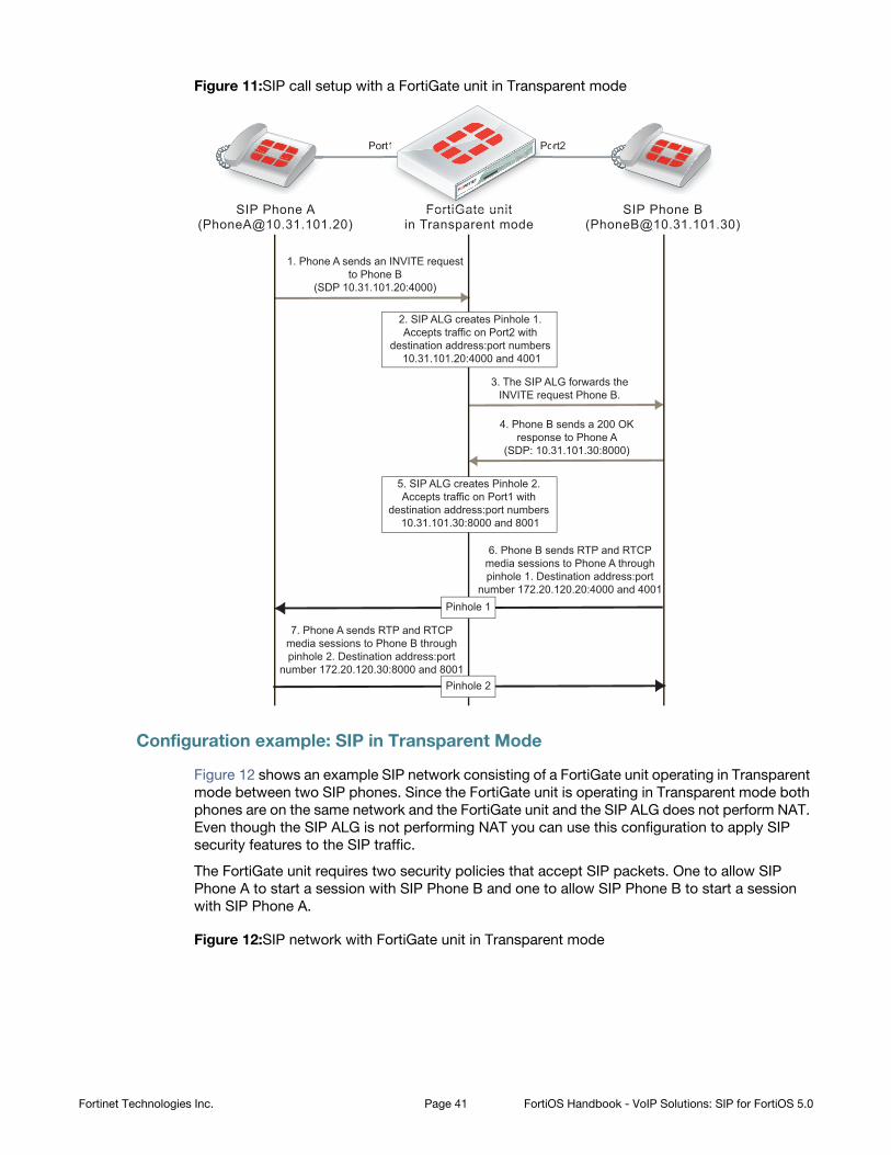
Figure 11:SIP call setup with a FortiGate unit in Transparent mode
Configuration example: SIP in Transparent Mode
Figure 12 shows an example SIP network consisting of a FortiGate unit operating in Transparent
mode between two SIP phones. Since the FortiGate unit is operating in Transparent mode both
phones are on the same network and the FortiGate unit and the SIP ALG does not perform NAT.
Even though the SIP ALG is not performing NAT you can use this configuration to apply SIP
security features to the SIP traffic.
The FortiGate unit requires two security policies that accept SIP packets. One to allow SIP
Phone A to start a session with SIP Phone B and one to allow SIP Phone B to start a session
with SIP Phone A.
Figure 12:SIP network with FortiGate unit in Transparent mode
FortiGate unitin Transparent mode
SIP Phone A([email protected])
SIP Phone B([email protected])
1. Phone A sends an INVITE requestto Phone B
(SDP 10.31.101.20:4000)
3. The SIP ALG forwards theINVITE request Phone B.
4. Phone B sends a 200 OKresponse to Phone A
(SDP: 10.31.101.30:8000)
6. Phone B sends RTP and RTCPmedia sessions to Phone A throughpinhole 1. Destination address:port
number 172.20.120.20:4000 and 4001
7. Phone A sends RTP and RTCPmedia sessions to Phone B throughpinhole 2. Destination address:port
number 172.20.120.30:8000 and 8001
2. SIP ALG creates Pinhole 1.Accepts traffic on Port2 with
destination address:port numbers 10.31.101.20:4000 and 4001
5. SIP ALG creates Pinhole 2.Accepts traffic on Port1 with
destination address:port numbers 10.31.101.30:8000 and 8001
Pinhole 1
Pinhole 2
Port1 Port2
Fortt GiGiGiGate unit
rt1 PoP
Fortinet Technologies Inc. Page 41 FortiOS Handbook - VoIP Solutions: SIP for FortiOS 5.0
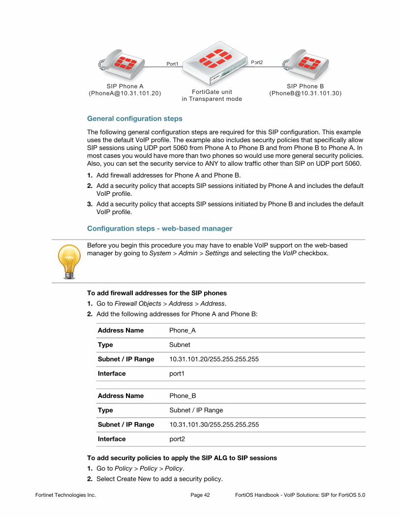
General configuration steps
The following general configuration steps are required for this SIP configuration. This example
uses the default VoIP profile. The example also includes security policies that specifically allow
SIP sessions using UDP port 5060 from Phone A to Phone B and from Phone B to Phone A. In
most cases you would have more than two phones so would use more general security policies.
Also, you can set the security service to ANY to allow traffic other than SIP on UDP port 5060.
1. Add firewall addresses for Phone A and Phone B.
2. Add a security policy that accepts SIP sessions initiated by Phone A and includes the default
VoIP profile.
3. Add a security policy that accepts SIP sessions initiated by Phone B and includes the default
VoIP profile.
Configuration steps - web-based manager
To add firewall addresses for the SIP phones
1. Go to Firewall Objects > Address > Address.
2. Add the following addresses for Phone A and Phone B:
To add security policies to apply the SIP ALG to SIP sessions
1. Go to Policy > Policy > Policy.
2. Select Create New to add a security policy.
FortiGate unitin Transparent mode
SIP Phone A([email protected])
SIP Phone B([email protected])
Port1 Port21 Po
Before you begin this procedure you may have to enable VoIP support on the web-based
manager by going to System > Admin > Settings and selecting the VoIP checkbox.
Address Name Phone_A
Type Subnet
Subnet / IP Range 10.31.101.20/255.255.255.255
Interface port1
Address Name Phone_B
Type Subnet / IP Range
Subnet / IP Range 10.31.101.30/255.255.255.255
Interface port2
Fortinet Technologies Inc. Page 42 FortiOS Handbook - VoIP Solutions: SIP for FortiOS 5.0
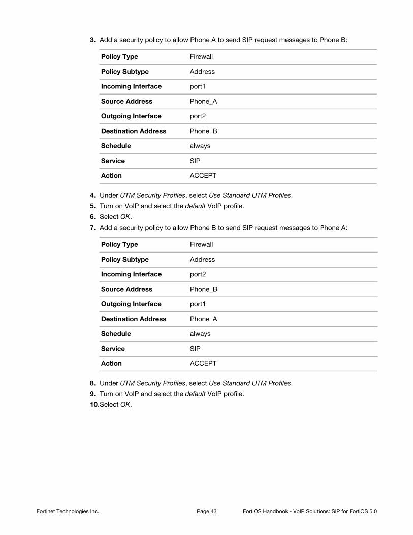
3. Add a security policy to allow Phone A to send SIP request messages to Phone B:
4. Under UTM Security Profiles, select Use Standard UTM Profiles.
5. Turn on VoIP and select the default VoIP profile.
6. Select OK.
7. Add a security policy to allow Phone B to send SIP request messages to Phone A:
8. Under UTM Security Profiles, select Use Standard UTM Profiles.
9. Turn on VoIP and select the default VoIP profile.
10.Select OK.
Policy Type Firewall
Policy Subtype Address
Incoming Interface port1
Source Address Phone_A
Outgoing Interface port2
Destination Address Phone_B
Schedule always
Service SIP
Action ACCEPT
Policy Type Firewall
Policy Subtype Address
Incoming Interface port2
Source Address Phone_B
Outgoing Interface port1
Destination Address Phone_A
Schedule always
Service SIP
Action ACCEPT
Fortinet Technologies Inc. Page 43 FortiOS Handbook - VoIP Solutions: SIP for FortiOS 5.0
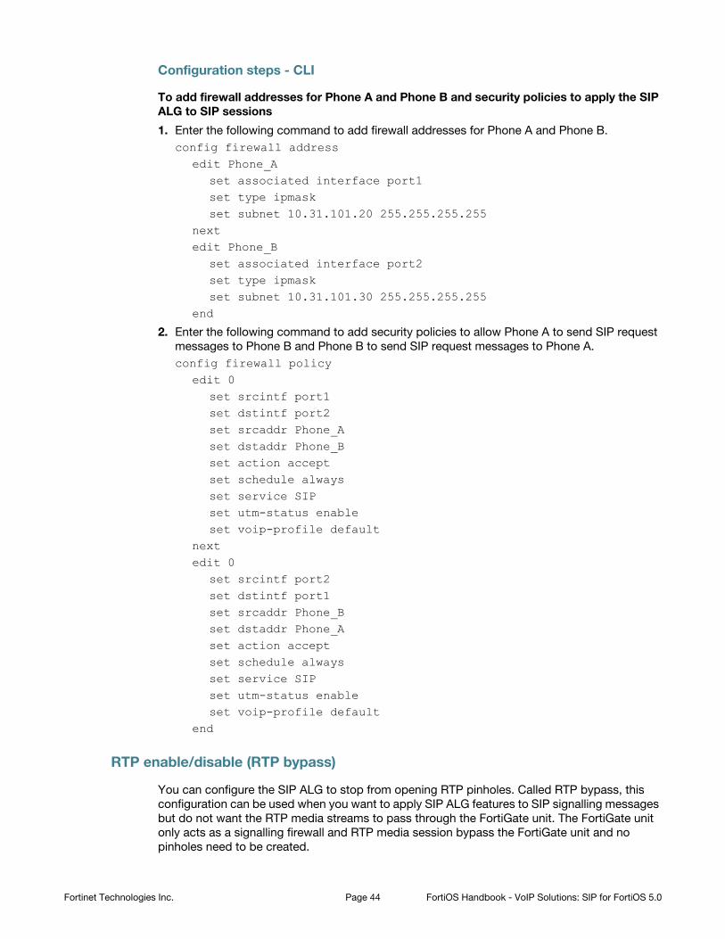
Configuration steps - CLI
To add firewall addresses for Phone A and Phone B and security policies to apply the SIP
ALG to SIP sessions
1. Enter the following command to add firewall addresses for Phone A and Phone B.
config firewall addressedit Phone_A
set associated interface port1set type ipmaskset subnet 10.31.101.20 255.255.255.255
nextedit Phone_B
set associated interface port2set type ipmaskset subnet 10.31.101.30 255.255.255.255
end
2. Enter the following command to add security policies to allow Phone A to send SIP request
messages to Phone B and Phone B to send SIP request messages to Phone A.
config firewall policyedit 0
set srcintf port1set dstintf port2set srcaddr Phone_Aset dstaddr Phone_Bset action acceptset schedule alwaysset service SIPset utm-status enableset voip-profile default
nextedit 0
set srcintf port2set dstintf port1set srcaddr Phone_Bset dstaddr Phone_Aset action acceptset schedule alwaysset service SIPset utm-status enableset voip-profile default
end
RTP enable/disable (RTP bypass)
You can configure the SIP ALG to stop from opening RTP pinholes. Called RTP bypass, this
configuration can be used when you want to apply SIP ALG features to SIP signalling messages
but do not want the RTP media streams to pass through the FortiGate unit. The FortiGate unit
only acts as a signalling firewall and RTP media session bypass the FortiGate unit and no
pinholes need to be created.
Fortinet Technologies Inc. Page 44 FortiOS Handbook - VoIP Solutions: SIP for FortiOS 5.0
Enter the following command to enable RTP bypass in a VoIP profile by disabling opening RTP
pinholes:
config voip profileedit VoIP_Pro_1
config sipset rtp disable
endend
Opening and closing SIP register, contact, via and record-route pinholes
You can use the open-register-pinhole, open-contact-pinhole, open-via-port,
and open-record-route-pinhole VoIP profile CLI options to control whether the FortiGate
unit opens various pinholes.
If open-register-pinhole is enabled (the default setting) the FortiGate unit opens pinholes
for SIP Register request messages. You can disable open-register-pinhole so that the
FortiGate unit does not open pinholes for SIP Register request messages.
If open-contact-pinhole is enabled (the default setting) the FortiGate unit opens pinholes
for non-Register SIP request messages. You can disable open-contact-pinhole so that the
FortiGate unit does not open pinholes for non-register requests. Non-register pinholes are
usually opened for SIP INVITE requests.
If open-via-pinhole is disabled (the default setting) the FortiGate unit does not open
pinholes for Via messages. You can enable open-via-pinhole so that the FortiGate unit
opens pinholes for Via messages.
If open-record-route-pinhole is enabled (the default setting) the FortiGate unit opens
pinholes for Record-Route messages. You can disable open-record-route-pinhole so
that the FortiGate unit does not open pinholes for Record-Route messages.
Usually you would want to open these pinholes. Keeping them closed may prevent SIP from
functioning properly through the FortiGate unit. They can be disabled, however, for interconnect
scenarios (where all SIP traffic is between proxies and traveling over a single session). In some
cases these settings can also be disabled in access scenarios if it is known that all users will be
registering regularly so that their contact information can be learned from the register request.
You might want to prevent pinholes from being opened to avoid creating a pinhole for every
register or non-register request. Each pinhole uses additional system memory, which can affect
system performance if there are hundreds or thousands of users, and requires refreshing which
can take a relatively long amount of time if there are thousands of active calls.
To configure a VoIP profile to prevent opening register and non-register pinholes:
config voip profileedit VoIP_Pro_1
config sipset open-register-pinhole disableset open-contact-pinhole disable
endend
In some cases you may not want to open pinholes for the port numbers specified in SIP Contact
headers. For example, in an interconnect scenario when a FortiGate unit is installed between
two SIP servers and the only SIP traffic through the FortiGate unit is between these SIP servers
pinholes may not need to be opened for the port numbers specified in the Contact header lines.
Fortinet Technologies Inc. Page 45 FortiOS Handbook - VoIP Solutions: SIP for FortiOS 5.0
If you disable open-register-pinhole then pinholes are not opened for ports in Contact
header lines in SIP Register messages. If you disable open-contact-pinhole then pinholes
are not opened for ports in Contact header lines in all SIP messages except SIP Register
messages.
Accepting SIP register responses
You can enable the VoIP profile open-via-pinhole options to accept a SIP Register
response message from a SIP server even if the source port of the Register response message
is different from the destination port.
Most SIP servers use 5060 as the source port in the SIP register response. Some SIP servers,
however, may use a different source port. If your SIP server uses a different source port, you can
enable open-via-pinhole and the SIP ALG will create a temporary pinhole when the
Register request from a SIP client includes a different source port. The FortiGate unit will accept
a SIP Register response with any source port number from the SIP server. Enter the following command to enable accepting any source port from a SIP server:
config voip profileedit VoIP_Pro_1
config sipset open-via-pinhole enable
endend
How the SIP ALG performs NAT
In most Network Address Translation (NAT) configurations, multiple hosts in a private network
share a single public IP address to access the Internet. For sessions originating on the private
network for the Internet, NAT replaces the private IP address of the PC in the private subnet with
the public IP address of the NAT device. The NAT device converts the public IP address for
responses from the Internet back into the private address before sending the response over the
private network to the originator of the session.
Using NAT with SIP is more complex because of the IP addresses and media stream port
numbers used in SIP message headers and bodies. When a caller on the private network sends
a SIP message to a phone or SIP server on the Internet, the SIP ALG must translate the private
network addresses in the SIP message to IP addresses and port numbers that are valid on the
Internet. When the response message is sent back to the caller, the SIP ALG must translate
these addresses back to valid private network addresses.
In addition, the media streams generated by the SIP session are independent of the SIP
message sessions and use varying port numbers that can also change during the media
session. The SIP ALG opens pinholes to accept these media sessions, using the information in
the SIP messages to determine the pinholes to open. The ALG may also perform port
translation on the media sessions.
When an INVITE message is received by the SIP ALG, the FortiGate unit extracts addressing
and port number information from the message header and stores it in a SIP dialog table.
Similar to an IP session table the data in the dialog table is used to translate addresses in
subsequent SIP messages that are part of the same SIP call.
When the SIP ALG receives a response to the INVITE message arrives, (for example, an ACK or
200 OK), the SIP ALG compares the addresses in the message fields against the entries in the
SIP dialog table to identify the call context of the message. The SIP ALG then translates
addresses in the SIP message before forwarding them to their destination.
Fortinet Technologies Inc. Page 46 FortiOS Handbook - VoIP Solutions: SIP for FortiOS 5.0
The addressing and port number information in SDP fields is used by the ALG to reserve ports
for the media session and create a NAT mapping between them and the ports in the SDP fields.
Because SDP uses sequential ports for the RTP and RTCP channels, the ALG provides
consecutive even-odd ports.
Source address translation
When a SIP call is started by a phone on a private network destined for a phone on the Internet,
only source address translation is required. The phone on the private network attempts to
contact the actual IP address of the phone on the Internet. However, the source address of the
phone on the private network is not routable on the Internet so the SIP ALG must translate all
private IP addresses in the SIP message into public IP addresses.
To configure the FortiGate for source address translation you add security policy that accepts
sessions from the internal network destined for the Internet. You must enable NAT for the
security policy and add a VoIP profile.
When a SIP request is received from the internal to the external network, the SIP ALG replaces
the private network IP addresses and port numbers in the SIP message with the IP address of
the FortiGate interface connected to the Internet. Depending on the content of the message, the
ALG translates addresses in the Via:, Contact:, Route:, and Record-Route: SIP header fields.
The message is then forwarded to the destination (either a VoIP phone or a SIP server on the
Internet).
The VoIP phone or server in the Internet sends responses to these SIP messages to the external
interface of the FortiGate unit. The addresses in the response messages are translated back
into private network addresses and the response is forwarded to the originator of the request.
For the RTP communication between the SIP phones, the SIP ALG opens pinholes to allow
media through the FortiGate unit on the dynamically assigned ports negotiated based on
information in the SDP and the Via:, Contact:, and Record-Route: header fields. The pinholes
also allow incoming packets to reach the Contact:, Via:, and Record-Route: IP addresses and
ports. When processing return traffic, the SIP ALG inserts the original Contact:, Via:, Route:, and
Record-Route: SIP fields back into the packets.
Destination address translation
Incoming calls are directed from a SIP phone on the Internet to the interface of the FortiGate
unit connected to the Internet. To receive these calls you must add a security policy to accept
SIP sessions from the Internet. The security policy requires a firewall virtual IP. SIP INVITE
messages from the Internet connect to the external IP address of the virtual IP. The SIP ALG
uses the destination address translation defined in the virtual IP to translated the addresses in
the SIP message to addresses on the private network.
When a 200 OK response message arrives from the private network, the SIP ALG translates the
addresses in the message to Internet addresses and opens pinholes for media sessions from
the private network to the Internet.
When the ACK message is received for the 200 OK, it is also intercepted by the SIP ALG. If the
ACK message contains SDP information, the SIP ALG checks to determine if the IP addresses
and port numbers are not changed from the previous INVITE. If they are, the SIP ALG deletes
pinholes and creates new ones as required. The ALG also monitors the Via:, Contact:, and
Record-Route: SIP fields and opens new pinholes as required.
Fortinet Technologies Inc. Page 47 FortiOS Handbook - VoIP Solutions: SIP for FortiOS 5.0
Call Re-invite messages
SIP Re-INVITE messages can dynamically add and remove media sessions during a call. When
new media sessions are added to a call the SIP ALG opens new pinholes and update SIP dialog
data. When media sessions are ended, the SIP ALG closes pinholes that are no longer needed
and removes SIP dialog data.
How the SIP ALG translates IP addresses in SIP headers
The SIP ALG applies NAT to SIP sessions by translating the IP addresses contained in SIP
headers. For example, the following SIP message contains most of the SIP fields that contain
addresses that need to be translated:
INVITE [email protected] SIP/2.0Via: SIP/2.0/UDP 172.20.120.50:5434From: [email protected]: [email protected]: [email protected]: [email protected]:5434Route: <sip:[email protected]:5060>Record-Route: <sip:[email protected]:5060>
How IP address translation is performed depends on whether source NAT or destination NAT is
applied to the session containing the message:
Source NAT translation of IP addresses in SIP messages
Source NAT translation occurs for SIP messages sent from a phone or server on a private
network to a phone or server on the Internet. The source addresses in the SIP header fields of
the message are typically set to IP addresses on the private network. The SIP ALG translates
these addresses to the address the FortiGate unit interface connected to the Internet.
SIP header NAT action
To: None
From: Replace private network address with IP address of FortiGate unit
interface connected to the Internet.
Call-ID: Replace private network address with IP address of FortiGate unit
interface connected to the Internet.
Via: Replace private network address with IP address of FortiGate unit
interface connected to the Internet.
Request-URI: None
Contact: Replace private network address with IP address of FortiGate unit
interface connected to the Internet.
Record-Route: Replace private network address with IP address of FortiGate unit
interface connected to the Internet.
Route: Replace private network address with IP address of FortiGate unit
interface connected to the Internet.
Table 4: Source NAT translation of IP addresses in SIP request messages
Fortinet Technologies Inc. Page 48 FortiOS Handbook - VoIP Solutions: SIP for FortiOS 5.0
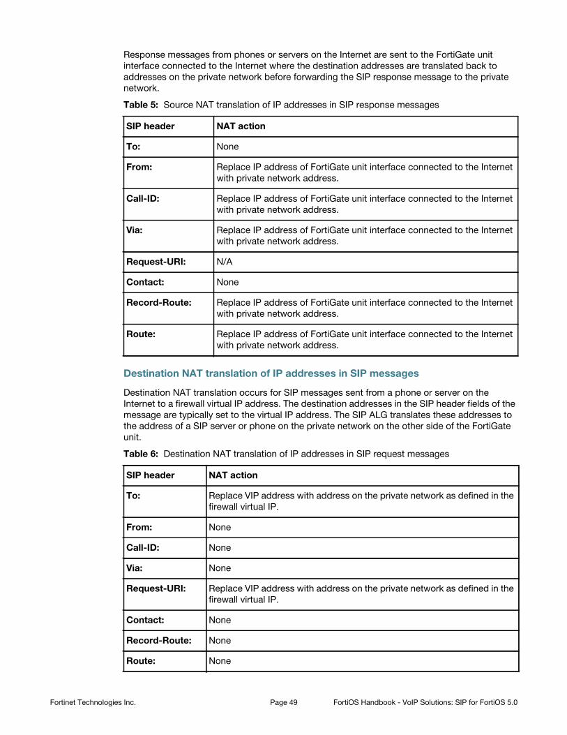
Response messages from phones or servers on the Internet are sent to the FortiGate unit
interface connected to the Internet where the destination addresses are translated back to
addresses on the private network before forwarding the SIP response message to the private
network.
SIP header NAT action
To: None
From: Replace IP address of FortiGate unit interface connected to the Internet
with private network address.
Call-ID: Replace IP address of FortiGate unit interface connected to the Internet
with private network address.
Via: Replace IP address of FortiGate unit interface connected to the Internet
with private network address.
Request-URI: N/A
Contact: None
Record-Route: Replace IP address of FortiGate unit interface connected to the Internet
with private network address.
Route: Replace IP address of FortiGate unit interface connected to the Internet
with private network address.
Destination NAT translation of IP addresses in SIP messages
Destination NAT translation occurs for SIP messages sent from a phone or server on the
Internet to a firewall virtual IP address. The destination addresses in the SIP header fields of the
message are typically set to the virtual IP address. The SIP ALG translates these addresses to
the address of a SIP server or phone on the private network on the other side of the FortiGate
unit.
SIP header NAT action
To: Replace VIP address with address on the private network as defined in the
firewall virtual IP.
From: None
Call-ID: None
Via: None
Request-URI: Replace VIP address with address on the private network as defined in the
firewall virtual IP.
Contact: None
Record-Route: None
Route: None
Table 5: Source NAT translation of IP addresses in SIP response messages
Table 6: Destination NAT translation of IP addresses in SIP request messages
Fortinet Technologies Inc. Page 49 FortiOS Handbook - VoIP Solutions: SIP for FortiOS 5.0
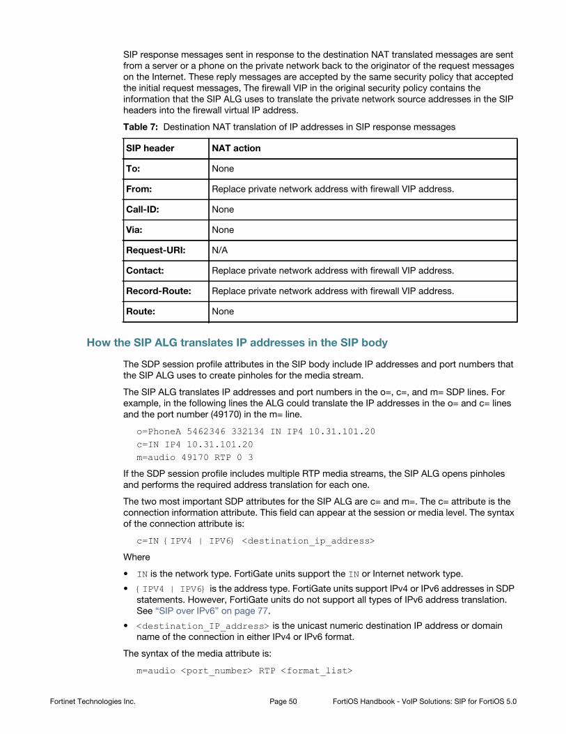
SIP response messages sent in response to the destination NAT translated messages are sent
from a server or a phone on the private network back to the originator of the request messages
on the Internet. These reply messages are accepted by the same security policy that accepted
the initial request messages, The firewall VIP in the original security policy contains the
information that the SIP ALG uses to translate the private network source addresses in the SIP
headers into the firewall virtual IP address.
SIP header NAT action
To: None
From: Replace private network address with firewall VIP address.
Call-ID: None
Via: None
Request-URI: N/A
Contact: Replace private network address with firewall VIP address.
Record-Route: Replace private network address with firewall VIP address.
Route: None
How the SIP ALG translates IP addresses in the SIP body
The SDP session profile attributes in the SIP body include IP addresses and port numbers that
the SIP ALG uses to create pinholes for the media stream.
The SIP ALG translates IP addresses and port numbers in the o=, c=, and m= SDP lines. For
example, in the following lines the ALG could translate the IP addresses in the o= and c= lines
and the port number (49170) in the m= line.
o=PhoneA 5462346 332134 IN IP4 10.31.101.20c=IN IP4 10.31.101.20m=audio 49170 RTP 0 3
If the SDP session profile includes multiple RTP media streams, the SIP ALG opens pinholes
and performs the required address translation for each one.
The two most important SDP attributes for the SIP ALG are c= and m=. The c= attribute is the
connection information attribute. This field can appear at the session or media level. The syntax
of the connection attribute is:
c=IN {IPV4 | IPV6} <destination_ip_address>
Where
• IN is the network type. FortiGate units support the IN or Internet network type.
• {IPV4 | IPV6} is the address type. FortiGate units support IPv4 or IPv6 addresses in SDP
statements. However, FortiGate units do not support all types of IPv6 address translation.
See “SIP over IPv6” on page 77.
• <destination_IP_address> is the unicast numeric destination IP address or domain
name of the connection in either IPv4 or IPv6 format.
The syntax of the media attribute is:
m=audio <port_number> RTP <format_list>
Table 7: Destination NAT translation of IP addresses in SIP response messages
Fortinet Technologies Inc. Page 50 FortiOS Handbook - VoIP Solutions: SIP for FortiOS 5.0
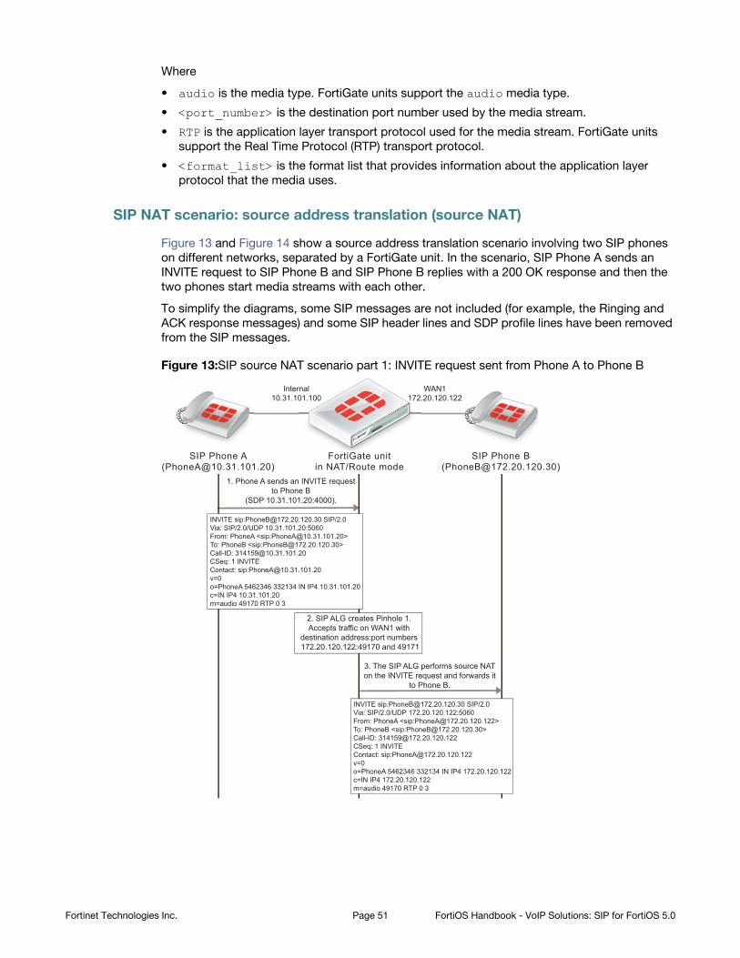
Where
• audio is the media type. FortiGate units support the audio media type.
• <port_number> is the destination port number used by the media stream.
• RTP is the application layer transport protocol used for the media stream. FortiGate units
support the Real Time Protocol (RTP) transport protocol.
• <format_list> is the format list that provides information about the application layer
protocol that the media uses.
SIP NAT scenario: source address translation (source NAT)
Figure 13 and Figure 14 show a source address translation scenario involving two SIP phones
on different networks, separated by a FortiGate unit. In the scenario, SIP Phone A sends an
INVITE request to SIP Phone B and SIP Phone B replies with a 200 OK response and then the
two phones start media streams with each other.
To simplify the diagrams, some SIP messages are not included (for example, the Ringing and
ACK response messages) and some SIP header lines and SDP profile lines have been removed
from the SIP messages.
Figure 13:SIP source NAT scenario part 1: INVITE request sent from Phone A to Phone B
FortiGate unitin NAT/Route mode
SIP Phone A([email protected])
SIP Phone B([email protected])
1. Phone A sends an INVITE requestto Phone B
(SDP 10.31.101.20:4000).
3. The SIP ALG performs source NATon the INVITE request and forwards it
to Phone B.
2. SIP ALG creates Pinhole 1.Accepts traffic on WAN1 with
destination address:port numbers 172.20.120.122:49170 and 49171
Internal10.31.101.100
WAN1172.20.120.122
INVITE sip:[email protected] SIP/2.0Via: SIP/2.0/UDP 10.31.101.20:5060From: PhoneA <sip:[email protected]>To: PhoneB <sip:[email protected]>Call-ID: [email protected]: 1 INVITEContact: sip:[email protected]=0o=PhoneA 5462346 332134 IN IP4 10.31.101.20c=IN IP4 10.31.101.20m=audio 49170 RTP 0 3
INVITE sip:[email protected] SIP/2.0Via: SIP/2.0/UDP 172.20.120.122:5060From: PhoneA <sip:[email protected]>To: PhoneB <sip:[email protected]>Call-ID: [email protected]: 1 INVITEContact: sip:[email protected]=0o=PhoneA 5462346 332134 IN IP4 172.20.120.122c=IN IP4 172.20.120.122m=audio 49170 RTP 0 3
Fortinet Technologies Inc. Page 51 FortiOS Handbook - VoIP Solutions: SIP for FortiOS 5.0
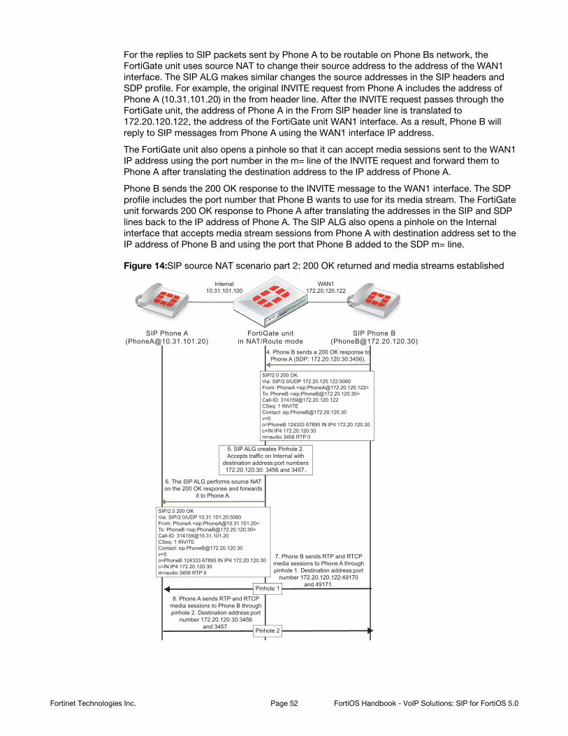
For the replies to SIP packets sent by Phone A to be routable on Phone Bs network, the
FortiGate unit uses source NAT to change their source address to the address of the WAN1
interface. The SIP ALG makes similar changes the source addresses in the SIP headers and
SDP profile. For example, the original INVITE request from Phone A includes the address of
Phone A (10.31.101.20) in the from header line. After the INVITE request passes through the
FortiGate unit, the address of Phone A in the From SIP header line is translated to
172.20.120.122, the address of the FortiGate unit WAN1 interface. As a result, Phone B will
reply to SIP messages from Phone A using the WAN1 interface IP address.
The FortiGate unit also opens a pinhole so that it can accept media sessions sent to the WAN1
IP address using the port number in the m= line of the INVITE request and forward them to
Phone A after translating the destination address to the IP address of Phone A.
Phone B sends the 200 OK response to the INVITE message to the WAN1 interface. The SDP
profile includes the port number that Phone B wants to use for its media stream. The FortiGate
unit forwards 200 OK response to Phone A after translating the addresses in the SIP and SDP
lines back to the IP address of Phone A. The SIP ALG also opens a pinhole on the Internal
interface that accepts media stream sessions from Phone A with destination address set to the
IP address of Phone B and using the port that Phone B added to the SDP m= line.
Figure 14:SIP source NAT scenario part 2: 200 OK returned and media streams established
6. The SIP ALG performs source NATon the 200 OK response and forwards
it to Phone A.
4. Phone B sends a 200 OK response toPhone A (SDP: 172.20.120.30:3456).
7. Phone B sends RTP and RTCPmedia sessions to Phone A throughpinhole 1. Destination address:port
number 172.20.120.122:49170and 49171.
8. Phone A sends RTP and RTCPmedia sessions to Phone B throughpinhole 2. Destination address:port
number 172.20.120.30:3456and 3457.
5. SIP ALG creates Pinhole 2.Accepts traffic on Internal with
destination address:port numbers 172.20.120.30: 3456 and 3457..
Pinhole 1
Pinhole 2
SIP/2.0 200 OKVia: SIP/2.0/UDP 172.20.120.122:5060From: PhoneA <sip:[email protected]>To: PhoneB <sip:[email protected]>Call-ID: [email protected]: 1 INVITEContact: sip:[email protected]=0o=PhoneB 124333 67895 IN IP4 172.20.120.30c=IN IP4 172.20.120.30m=audio 3456 RTP 0
SIP/2.0 200 OKVia: SIP/2.0/UDP 10.31.101.20:5060From: PhoneA <sip:[email protected]>To: PhoneB <sip:[email protected]>Call-ID: [email protected]: 1 INVITEContact: sip:[email protected]=0o=PhoneB 124333 67895 IN IP4 172.20.120.30c=IN IP4 172.20.120.30m=audio 3456 RTP 0
FortiGate unitin NAT/Route mode
SIP Phone A([email protected])
SIP Phone B([email protected])
Internal10.31.101.100
WAN1172.20.120.122
Fortinet Technologies Inc. Page 52 FortiOS Handbook - VoIP Solutions: SIP for FortiOS 5.0
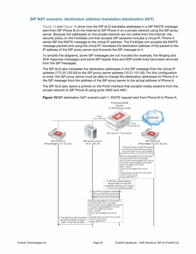
SIP NAT scenario: destination address translation (destination NAT)
Figure 15 and Figure 16 show how the SIP ALG translates addresses in a SIP INVITE message
sent from SIP Phone B on the Internet to SIP Phone A on a private network using the SIP proxy
server. Because the addresses on the private network are not visible from the Internet, the
security policy on the FortiGate unit that accepts SIP sessions includes a virtual IP. Phone A
sends SIP the INVITE message to the virtual IP address. The FortiGate unit accepts the INVITE
message packets and using the virtual IP, translates the destination address of the packet to the
IP address of the SIP proxy server and forwards the SIP message to it.
To simplify the diagrams, some SIP messages are not included (for example, the Ringing and
ACK response messages) and some SIP header lines and SDP profile lines have been removed
from the SIP messages.
The SIP ALG also translates the destination addresses in the SIP message from the virtual IP
address (172.20.120.50) to the SIP proxy server address (10.31.101.50). For this configuration
to work, the SIP proxy server must be able to change the destination addresses for Phone A in
the SIP message from the address of the SIP proxy server to the actual address of Phone A.
The SIP ALG also opens a pinhole on the Port2 interface that accepts media sessions from the
private network to SIP Phone B using ports 4900 and 4901.
Figure 15:SIP destination NAT scenario part 1: INVITE request sent from Phone B to Phone A
Port1172.20.120.141
SIP Virtual IP: 172.20.120.50
Port210.11.101.100
FortiGate-620BCluster
In NAT/Route mode
1. Phone B sends an INVITE requestfor Phone A to the SIP Proxy ServerVirtual IP (SDP 172.20.120.30:4900)
SIP proxy server10.31.101.50
SIP Phone A([email protected])
SIP Phone B([email protected])
3. The SIP ALG performs destinationNAT on the INVITE request and
forwards it to the SIP proxy server.
4. The SIP proxy server forwardsthe INVITE request to Phone A
(SDP: 172.20.120.30:4900)
2. SIP ALG creates Pinhole 1.Accepts traffic on Port2 with
destination address:port numbers 172.20.120.30:4900 and 4901
INVITE sip:[email protected] SIP/2.0Via: SIP/2.0/UDP 172.20.120.50:5060From: PhoneB <sip:[email protected]>To: PhoneA <sip:[email protected]>Call-ID: [email protected]: 1 INVITEContact: sip:[email protected]=0o=PhoneB 2346 134 IN IP4 172.20.120.30c=IN IP4 172.20.120.30m=audio 4900 RTP 0 3
INVITE sip:[email protected] SIP/2.0Via: SIP/2.0/UDP 10.31.101.50:5060From: PhoneB <sip:[email protected]>To: PhoneA <sip:[email protected]>Call-ID: [email protected]: 1 INVITEContact: sip:[email protected]=0o=PhoneB 2346 134 IN IP4 172.20.120.30c=IN IP4 172.20.120.30m=audio 4900 RTP 0 3
SIP PhPhhhhP oononneee A SIPP PhPhPhhhhhPhhooonnee B
PoP1117172.2 20.
000
Fortinet Technologies Inc. Page 53 FortiOS Handbook - VoIP Solutions: SIP for FortiOS 5.0
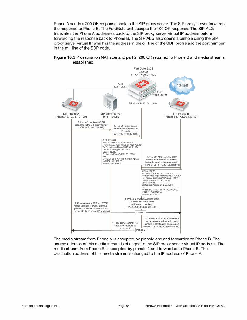
Phone A sends a 200 OK response back to the SIP proxy server. The SIP proxy server forwards
the response to Phone B. The FortiGate unit accepts the 100 OK response. The SIP ALG
translates the Phone A addresses back to the SIP proxy server virtual IP address before
forwarding the response back to Phone B. The SIP ALG also opens a pinhole using the SIP
proxy server virtual IP which is the address in the o= line of the SDP profile and the port number
in the m= line of the SDP code.
Figure 16:SIP destination NAT scenario part 2: 200 OK returned to Phone B and media streams
established
The media stream from Phone A is accepted by pinhole one and forwarded to Phone B. The
source address of this media stream is changed to the SIP proxy server virtual IP address. The
media stream from Phone B is accepted by pinhole 2 and forwarded to Phone B. The
destination address of this media stream is changed to the IP address of Phone A.
SIP proxy server10.31.101.50
SIP Phone A([email protected])
SIP Phone B([email protected])
5. Phone A sends a 200 OKresponse to the SIP proxy server
(SDP: 10.31.101.20:8888)6. The SIP proxy serverforwards the response to
Phone B(SDP: 10.31.101.20:8888)
7. The SIP ALG NATs the SDPaddress to the Virtual IP addressbefore forwarding the response to
Phone B (SDP: 172.20.120.50:5500)
9. Phone A sends RTP and RTCPmedia sessions to Phone B throughpinhole 1. Destination address:port
number 172.20.120.30:4900 and 4901
10. Phone B sends RTP and RTCPmedia sessions to Phone A throughpinhole 2. Destination address:port
number 172.20.120.50:5500 and 5501.11. The SIP ALG NATs the
destination address to10.31.101.20.
8. Pinhole 2 created. Accepts trafficon Port1 with destination
address:port numbers 172.20.120.50:5500 and 5501
Pinhole 1
Pinhole 2
SIP/2.0 200 OKVia: SIP/2.0/UDP 10.31.101.50:5060From: PhoneB <sip:[email protected]>To: PhoneA <sip:[email protected]>Call-ID: [email protected]: 1 INVITEContact: sip:[email protected]=0o=PhoneB 2346 134 IN IP4 172.20.120.30c=IN IP4 10.31.101.20m=audio 5500 RTP 0
SIP/2.0 200 OKVia: SIP/2.0/UDP 172.20.120.50:5060From: PhoneB <sip:[email protected]>To: PhoneA <sip:[email protected]>Call-ID: [email protected]: 1 INVITEContact: sip:[email protected]=0o=PhoneB 2346 134 IN IP4 172.20.120.30c=IN IP4 172.20.120.50m=audio 5500 RTP 0
Port1172.20.120.141
SIP Virtual IP: 172.20.120.50
Port210.11.101.100
FortiGate-620BCluster
In NAT/Route mode
PoP1117172.2 20.
000
Fortinet Technologies Inc. Page 54 FortiOS Handbook - VoIP Solutions: SIP for FortiOS 5.0
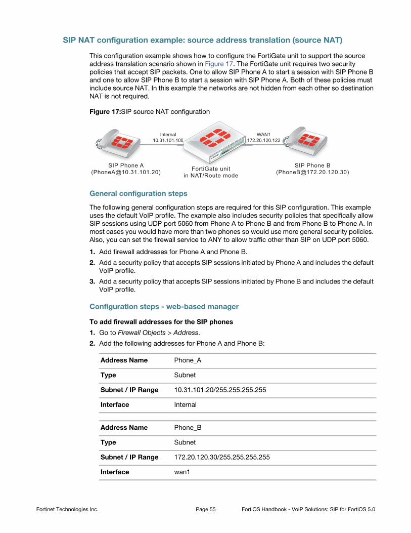
SIP NAT configuration example: source address translation (source NAT)
This configuration example shows how to configure the FortiGate unit to support the source
address translation scenario shown in Figure 17. The FortiGate unit requires two security
policies that accept SIP packets. One to allow SIP Phone A to start a session with SIP Phone B
and one to allow SIP Phone B to start a session with SIP Phone A. Both of these policies must
include source NAT. In this example the networks are not hidden from each other so destination
NAT is not required.
Figure 17:SIP source NAT configuration
General configuration steps
The following general configuration steps are required for this SIP configuration. This example
uses the default VoIP profile. The example also includes security policies that specifically allow
SIP sessions using UDP port 5060 from Phone A to Phone B and from Phone B to Phone A. In
most cases you would have more than two phones so would use more general security policies.
Also, you can set the firewall service to ANY to allow traffic other than SIP on UDP port 5060.
1. Add firewall addresses for Phone A and Phone B.
2. Add a security policy that accepts SIP sessions initiated by Phone A and includes the default
VoIP profile.
3. Add a security policy that accepts SIP sessions initiated by Phone B and includes the default
VoIP profile.
Configuration steps - web-based manager
To add firewall addresses for the SIP phones
1. Go to Firewall Objects > Address.
2. Add the following addresses for Phone A and Phone B:
Address Name Phone_A
Type Subnet
Subnet / IP Range 10.31.101.20/255.255.255.255
Interface Internal
Address Name Phone_B
Type Subnet
Subnet / IP Range 172.20.120.30/255.255.255.255
Interface wan1
FortiGate unitin NAT/Route mode
SIP Phone A([email protected])
SIP Phone B([email protected])
Internal10.31.101.100
WAN1172.20.120.122
F tiGG t it
100 171 2
Fortinet Technologies Inc. Page 55 FortiOS Handbook - VoIP Solutions: SIP for FortiOS 5.0
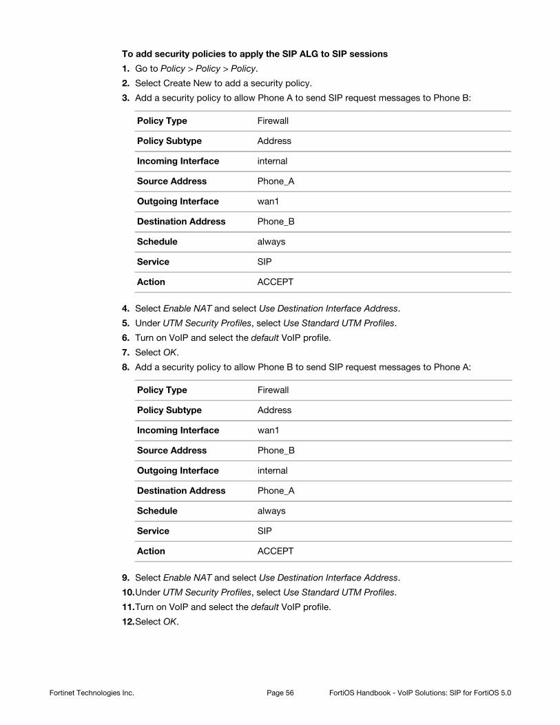
To add security policies to apply the SIP ALG to SIP sessions
1. Go to Policy > Policy > Policy.
2. Select Create New to add a security policy.
3. Add a security policy to allow Phone A to send SIP request messages to Phone B:
4. Select Enable NAT and select Use Destination Interface Address.
5. Under UTM Security Profiles, select Use Standard UTM Profiles.
6. Turn on VoIP and select the default VoIP profile.
7. Select OK.
8. Add a security policy to allow Phone B to send SIP request messages to Phone A:
9. Select Enable NAT and select Use Destination Interface Address.
10.Under UTM Security Profiles, select Use Standard UTM Profiles.
11.Turn on VoIP and select the default VoIP profile.
12.Select OK.
Policy Type Firewall
Policy Subtype Address
Incoming Interface internal
Source Address Phone_A
Outgoing Interface wan1
Destination Address Phone_B
Schedule always
Service SIP
Action ACCEPT
Policy Type Firewall
Policy Subtype Address
Incoming Interface wan1
Source Address Phone_B
Outgoing Interface internal
Destination Address Phone_A
Schedule always
Service SIP
Action ACCEPT
Fortinet Technologies Inc. Page 56 FortiOS Handbook - VoIP Solutions: SIP for FortiOS 5.0

Configuration steps - CLI
To add firewall addresses for Phone A and Phone B and security policies to apply the SIP
ALG to SIP sessions
1 Enter the following command to add firewall addresses for Phone A and Phone B.
config firewall addressedit Phone_A
set associated interface internalset type ipmaskset subnet 10.31.101.20 255.255.255.255
nextedit Phone_B
set associated interface wan1set type ipmaskset subnet 172.20.120.30 255.255.255.255
end
2 Enter the following command to add security policies to allow Phone A to send SIP request
messages to Phone B and Phone B to send SIP request messages to Phone A.
config firewall policyedit 0
set srcintf internalset dstintf wan1set srcaddr Phone_Aset dstaddr Phone_Bset action acceptset schedule alwaysset service SIPset nat enableset utm-status enableset voip-profile default
nextedit 0
set srcintf wan1set dstintf internalset srcaddr Phone_Bset dstaddr Phone_Aset action acceptset schedule alwaysset service SIPset nat enableset utm-status enableset voip-profile default
end
Fortinet Technologies Inc. Page 57 FortiOS Handbook - VoIP Solutions: SIP for FortiOS 5.0

SIP NAT configuration example: destination address translation (destination NAT)
This configuration example shows how to configure the FortiGate unit to support the destination
address translation scenario shown in Figure 18. The FortiGate unit requires two SIP security
policies:
• A destination NAT security policy that allows SIP messages to be sent from the Internet to
the private network. This policy must include destination NAT because the addresses on the
private network are not routable on the Internet.
• A source NAT security policy that allows SIP messages to be sent from the private network
to the Internet.
Figure 18:SIP destination NAT scenario part two: 200 OK returned to Phone B and media
streams established
General configuration steps
The following general configuration steps are required for this destination NAT SIP
configuration. This example uses the default VoIP profile.
1 Add the SIP proxy server firewall virtual IP.
2 Add a firewall address for the SIP proxy server on the private network.
3 Add a destination NAT security policy that accepts SIP sessions from the Internet destined
for the SIP proxy server virtual IP and translates the destination address to the IP address of
the SIP proxy server on the private network.
4 Add a security policy that accepts SIP sessions initiated by the SIP proxy server and
destined for the Internet.
Configuration steps - web-based manager
To add the SIP proxy server firewall virtual IP
1. Go to Firewall Objects > Virtual IP > Virtual IP and select Create New.
2. Add the SIP proxy server virtual IP.
Name SIP_Proxy_VIP
External Interface port1
Type Static NAT
External IP Address/Range 172.20.120.50
Mapped IP Address/Range 10.31.101.50
SIP proxy serverVirtual IP: 172.20.120.50
SIP proxy server10.31.101.50
SIP Phone A([email protected])
SIP Phone B([email protected])
Port1172.20.120.141
Port210.11.101.100
FortiGate-620BCluster
In NAT/Route mode
SIP PhPhhhP A SIP PPhhhhh B
PoP1117172.2 20.
000
Fortinet Technologies Inc. Page 58 FortiOS Handbook - VoIP Solutions: SIP for FortiOS 5.0
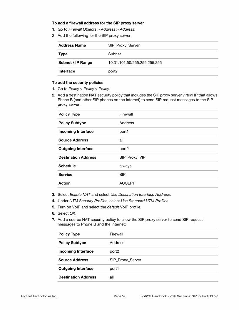
To add a firewall address for the SIP proxy server
1. Go to Firewall Objects > Address > Address.
2 Add the following for the SIP proxy server:
To add the security policies
1. Go to Policy > Policy > Policy.
2. Add a destination NAT security policy that includes the SIP proxy server virtual IP that allows
Phone B (and other SIP phones on the Internet) to send SIP request messages to the SIP
proxy server.
3. Select Enable NAT and select Use Destination Interface Address.
4. Under UTM Security Profiles, select Use Standard UTM Profiles.
5. Turn on VoIP and select the default VoIP profile.
6. Select OK.
7. Add a source NAT security policy to allow the SIP proxy server to send SIP request
messages to Phone B and the Internet:
Address Name SIP_Proxy_Server
Type Subnet
Subnet / IP Range 10.31.101.50/255.255.255.255
Interface port2
Policy Type Firewall
Policy Subtype Address
Incoming Interface port1
Source Address all
Outgoing Interface port2
Destination Address SIP_Proxy_VIP
Schedule always
Service SIP
Action ACCEPT
Policy Type Firewall
Policy Subtype Address
Incoming Interface port2
Source Address SIP_Proxy_Server
Outgoing Interface port1
Destination Address all
Fortinet Technologies Inc. Page 59 FortiOS Handbook - VoIP Solutions: SIP for FortiOS 5.0
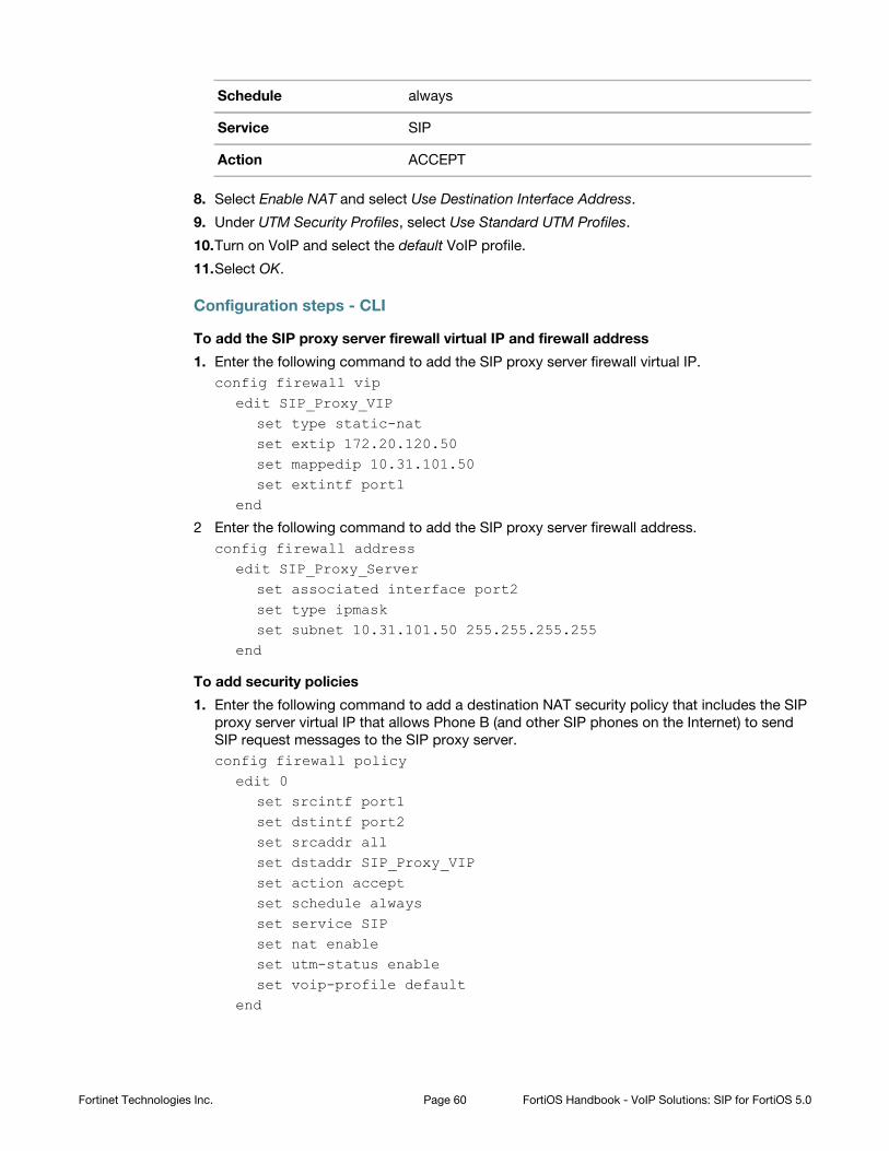
8. Select Enable NAT and select Use Destination Interface Address.
9. Under UTM Security Profiles, select Use Standard UTM Profiles.
10.Turn on VoIP and select the default VoIP profile.
11.Select OK.
Configuration steps - CLI
To add the SIP proxy server firewall virtual IP and firewall address
1. Enter the following command to add the SIP proxy server firewall virtual IP.
config firewall vipedit SIP_Proxy_VIP
set type static-natset extip 172.20.120.50set mappedip 10.31.101.50set extintf port1
end
2 Enter the following command to add the SIP proxy server firewall address.
config firewall addressedit SIP_Proxy_Server
set associated interface port2set type ipmaskset subnet 10.31.101.50 255.255.255.255
end
To add security policies
1. Enter the following command to add a destination NAT security policy that includes the SIP
proxy server virtual IP that allows Phone B (and other SIP phones on the Internet) to send
SIP request messages to the SIP proxy server.
config firewall policyedit 0
set srcintf port1set dstintf port2set srcaddr allset dstaddr SIP_Proxy_VIPset action acceptset schedule alwaysset service SIPset nat enableset utm-status enableset voip-profile default
end
Schedule always
Service SIP
Action ACCEPT
Fortinet Technologies Inc. Page 60 FortiOS Handbook - VoIP Solutions: SIP for FortiOS 5.0
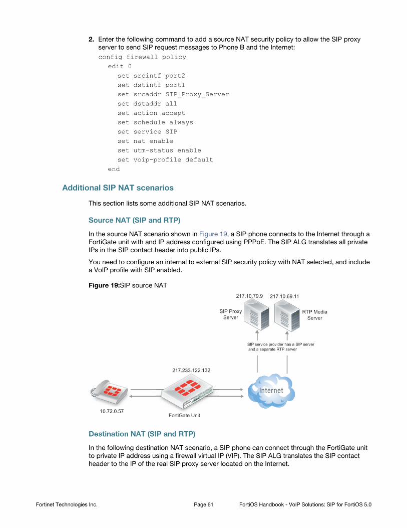
2. Enter the following command to add a source NAT security policy to allow the SIP proxy
server to send SIP request messages to Phone B and the Internet:
config firewall policyedit 0
set srcintf port2set dstintf port1set srcaddr SIP_Proxy_Serverset dstaddr allset action acceptset schedule alwaysset service SIPset nat enableset utm-status enableset voip-profile default
end
Additional SIP NAT scenarios
This section lists some additional SIP NAT scenarios.
Source NAT (SIP and RTP)
In the source NAT scenario shown in Figure 19, a SIP phone connects to the Internet through a
FortiGate unit with and IP address configured using PPPoE. The SIP ALG translates all private
IPs in the SIP contact header into public IPs.
You need to configure an internal to external SIP security policy with NAT selected, and include
a VoIP profile with SIP enabled.
Figure 19:SIP source NAT
Destination NAT (SIP and RTP)
In the following destination NAT scenario, a SIP phone can connect through the FortiGate unit
to private IP address using a firewall virtual IP (VIP). The SIP ALG translates the SIP contact
header to the IP of the real SIP proxy server located on the Internet.
10.72.0.57
217.233.122.132
RTP MediaServer
217.10.79.9 217.10.69.11
SIP service provider has a SIP server and a separate RTP server
SIP ProxyServer
FortiGate Unit
Fortinet Technologies Inc. Page 61 FortiOS Handbook - VoIP Solutions: SIP for FortiOS 5.0
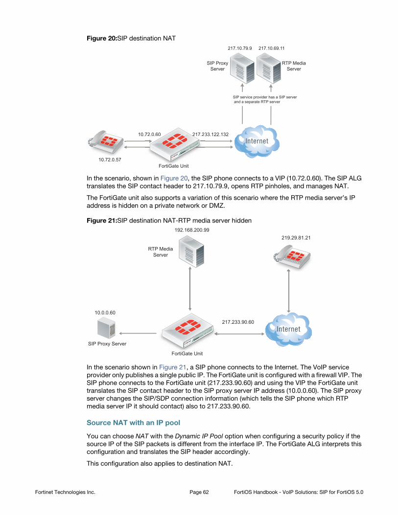
Figure 20:SIP destination NAT
In the scenario, shown in Figure 20, the SIP phone connects to a VIP (10.72.0.60). The SIP ALG
translates the SIP contact header to 217.10.79.9, opens RTP pinholes, and manages NAT.
The FortiGate unit also supports a variation of this scenario where the RTP media server’s IP
address is hidden on a private network or DMZ.
Figure 21:SIP destination NAT-RTP media server hidden
In the scenario shown in Figure 21, a SIP phone connects to the Internet. The VoIP service
provider only publishes a single public IP. The FortiGate unit is configured with a firewall VIP. The
SIP phone connects to the FortiGate unit (217.233.90.60) and using the VIP the FortiGate unit
translates the SIP contact header to the SIP proxy server IP address (10.0.0.60). The SIP proxy
server changes the SIP/SDP connection information (which tells the SIP phone which RTP
media server IP it should contact) also to 217.233.90.60.
Source NAT with an IP pool
You can choose NAT with the Dynamic IP Pool option when configuring a security policy if the
source IP of the SIP packets is different from the interface IP. The FortiGate ALG interprets this
configuration and translates the SIP header accordingly.
This configuration also applies to destination NAT.
10.72.0.57
SIP ProxyServer
217.233.122.132
FortiGate Unit
RTP MediaServer
217.10.79.9
SIP service provider has a SIP server and a separate RTP server
217.10.69.11
10.72.0.60 217.23
F tiiGG t U it
72.0.60
219.29.81.21
SIP Proxy Server
217.233.90.60
FortiGate Unit
RTP MediaServer
10.0.0.60
192.168.200.99
Fortinet Technologies Inc. Page 62 FortiOS Handbook - VoIP Solutions: SIP for FortiOS 5.0
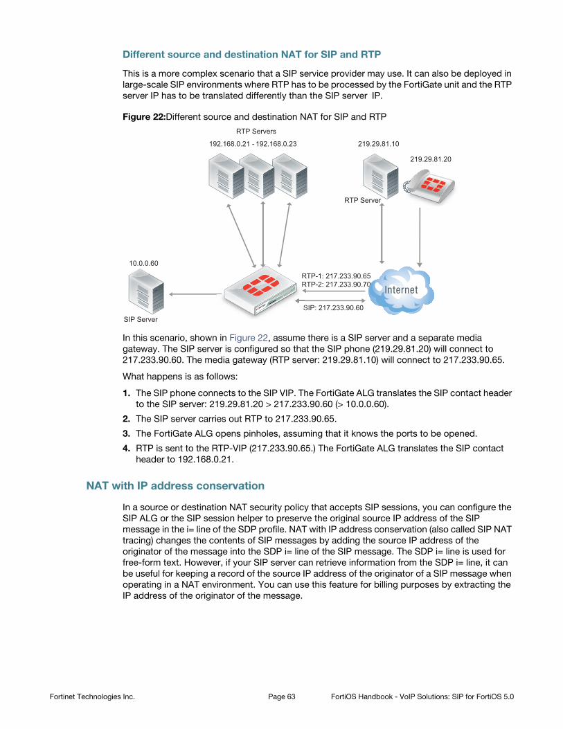
Different source and destination NAT for SIP and RTP
This is a more complex scenario that a SIP service provider may use. It can also be deployed in
large-scale SIP environments where RTP has to be processed by the FortiGate unit and the RTP
server IP has to be translated differently than the SIP server IP.
Figure 22:Different source and destination NAT for SIP and RTP
In this scenario, shown in Figure 22, assume there is a SIP server and a separate media
gateway. The SIP server is configured so that the SIP phone (219.29.81.20) will connect to
217.233.90.60. The media gateway (RTP server: 219.29.81.10) will connect to 217.233.90.65.
What happens is as follows:
1. The SIP phone connects to the SIP VIP. The FortiGate ALG translates the SIP contact header
to the SIP server: 219.29.81.20 > 217.233.90.60 (> 10.0.0.60).
2. The SIP server carries out RTP to 217.233.90.65.
3. The FortiGate ALG opens pinholes, assuming that it knows the ports to be opened.
4. RTP is sent to the RTP-VIP (217.233.90.65.) The FortiGate ALG translates the SIP contact
header to 192.168.0.21.
NAT with IP address conservation
In a source or destination NAT security policy that accepts SIP sessions, you can configure the
SIP ALG or the SIP session helper to preserve the original source IP address of the SIP
message in the i= line of the SDP profile. NAT with IP address conservation (also called SIP NAT
tracing) changes the contents of SIP messages by adding the source IP address of the
originator of the message into the SDP i= line of the SIP message. The SDP i= line is used for
free-form text. However, if your SIP server can retrieve information from the SDP i= line, it can
be useful for keeping a record of the source IP address of the originator of a SIP message when
operating in a NAT environment. You can use this feature for billing purposes by extracting the
IP address of the originator of the message.
219.29.81.20
SIP ServerSIP: 217.233.90.60
RTP Servers
10.0.0.60
192.168.0.23
RTP Server
219.29.81.10192.168.0.21 -
RTP-1: 217.233.90.65RTP-2: 217.233.90.70
S
RR
Fortinet Technologies Inc. Page 63 FortiOS Handbook - VoIP Solutions: SIP for FortiOS 5.0
Configuring SIP IP address conservation for the SIP ALG
You can use the following command to enable or disable SIP IP address conservation in a VoIP
profile for the SIP ALG. SIP IP address conservation is enabled by default in a VoIP profile.
config voip profileedit VoIP_Pro_1
config sipset nat-trace disable
endend
If the SIP message does not include an i= line and if the original source IP address of the traffic
(before NAT) was 10.31.101.20 then the FortiGate unit would add the following i= line.
i=(o=IN IP4 10.31.101.20)
You can also use the preserve-override option to configure the SIP ALG to either add the
original o= line to the end of the i= line or replace the i= line in the original message with a new
i= line in the same form as above for adding a new i= line.
By default, preserver-override is disabled and the SIP ALG adds the original o= line to the
end of the original i= line. Use the following command to configure the SIP ALG to replace the
original i= line:
config voip profileedit VoIP_Pro_1
config sipset preserve-override enable
endend
Configuring SIP IP address conservation for the SIP session helper
You can use the following command to enable or disable SIP IP address conservation for the
SIP session helper. IP address conservation is enabled by default for the SIP session helper.
config system settingsset sip-nat-trace disable
end
If the SIP message does not include an i= line and if the original source IP address of the traffic
(before NAT) was 10.31.101.20 then the FortiGate unit would add the following i= line.
i=(o=IN IP4 10.31.101.20)
Controlling how the SIP ALG NATs SIP contact header line addresses
You can enable contact-fixup so that the SIP ALG performs normal SIP NAT translation to
SIP contact headers as SIP messages pass through the FortiGate unit.
Disable contact-fixup if you do not want the SIP ALG to perform normal NAT translation of
the SIP contact header if a Record-Route header is also available. If contact-fixup is
disabled, the FortiGate ALG does the following with contact headers:
• For Contact in Requests, if a Record-Route header is present and the request comes from
the external network, the SIP Contact header is not translated.
• For Contact in Responses, if a Record-Route header is present and the response comes
from the external network, the SIP Contact header is not translated.
Fortinet Technologies Inc. Page 64 FortiOS Handbook - VoIP Solutions: SIP for FortiOS 5.0
If contact-fixup is disabled, the SIP ALG must be able to identify the external network. To
identify the external network, you must use the config system interface command to set
the external keyword to enable for the interface that is connected to the external network.
Enter the following command to perform normal NAT translation of the SIP contact header:
config voip profileedit VoIP_Pro_1
config sipset contact-fixup enable
endend
Controlling NAT for addresses in SDP lines
You can use the no-sdp-fixup option to control whether the FortiGate unit performs NAT on
addresses in SDP lines in the SIP message body.
The no-sdp-fixup option is disabled by default and the FortiGate unit performs NAT on
addresses in SDP lines. Enable this option if you don’t want the FortiGate unit to perform NAT
on the addresses in SDP lines.
config voip profileedit VoIP_Pro_1
config sipset no-sdp-fixup enable
endend
Translating SIP session destination ports
Using port forwarding virtual IPs you can change the destination port of SIP sessions as they
pass through the FortiGate unit.
This section describes:
• Translating SIP sessions to a different destination port
• Translating SIP sessions to multiple destination ports
Translating SIP sessions to a different destination port
To configure translating SIP sessions to a different destination port you must add a static NAT
virtual IP that translates tie SIP destination port to another port destination. In the example the
destination port is translated from 5060 to 50601. This configuration can be used if SIP sessions
uses different destination ports on different networks.
Fortinet Technologies Inc. Page 65 FortiOS Handbook - VoIP Solutions: SIP for FortiOS 5.0
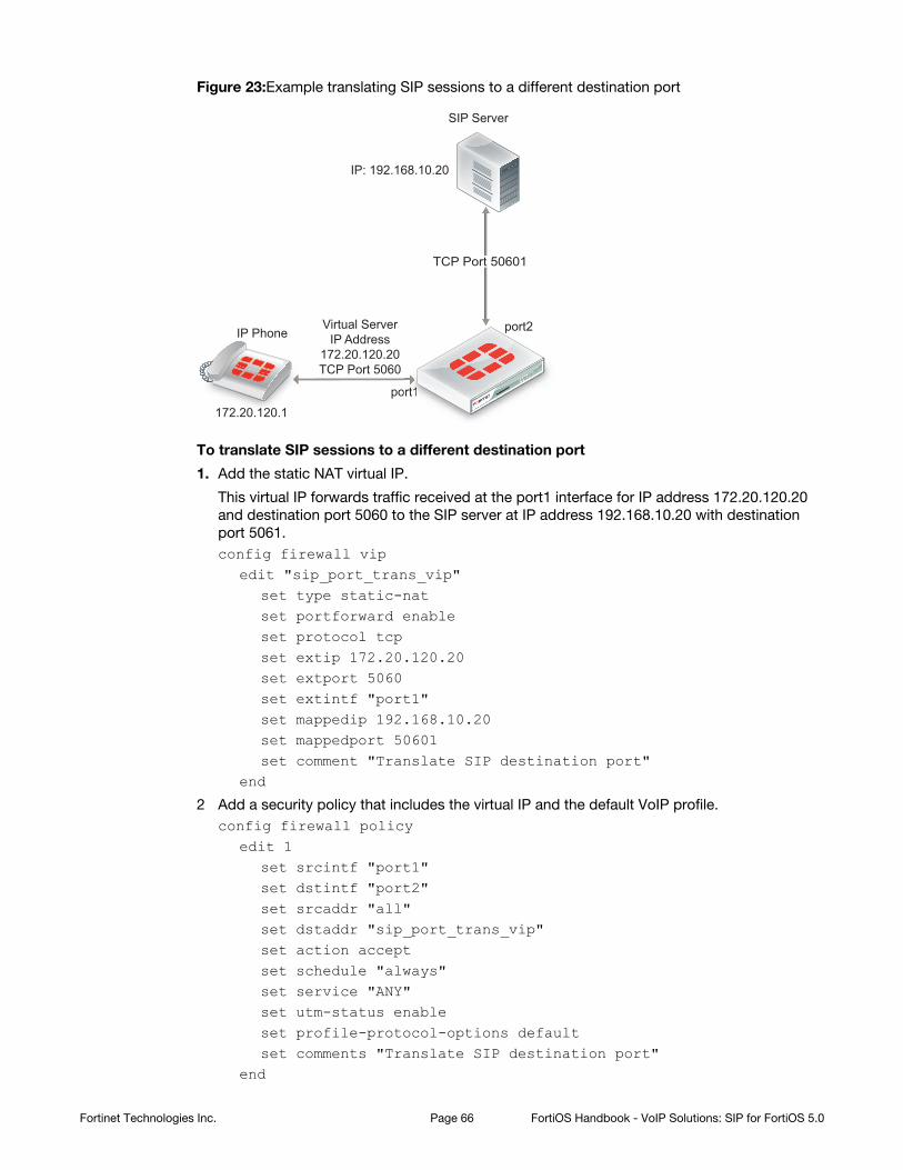
Figure 23:Example translating SIP sessions to a different destination port
To translate SIP sessions to a different destination port
1. Add the static NAT virtual IP.
This virtual IP forwards traffic received at the port1 interface for IP address 172.20.120.20
and destination port 5060 to the SIP server at IP address 192.168.10.20 with destination
port 5061.
config firewall vipedit "sip_port_trans_vip"
set type static-natset portforward enableset protocol tcpset extip 172.20.120.20set extport 5060set extintf "port1"set mappedip 192.168.10.20set mappedport 50601set comment "Translate SIP destination port"
end
2 Add a security policy that includes the virtual IP and the default VoIP profile.
config firewall policyedit 1
set srcintf "port1"set dstintf "port2"set srcaddr "all"set dstaddr "sip_port_trans_vip"set action acceptset schedule "always"set service "ANY"set utm-status enableset profile-protocol-options defaultset comments "Translate SIP destination port"
end
Virtual ServerIP Address
172.20.120.20TCP Port 5060
172.20.120.1
SIP Server
IP Phone
port1
port2
IP: 192.168.10.20
TCP Port 50601
ortt111111
Fortinet Technologies Inc. Page 66 FortiOS Handbook - VoIP Solutions: SIP for FortiOS 5.0
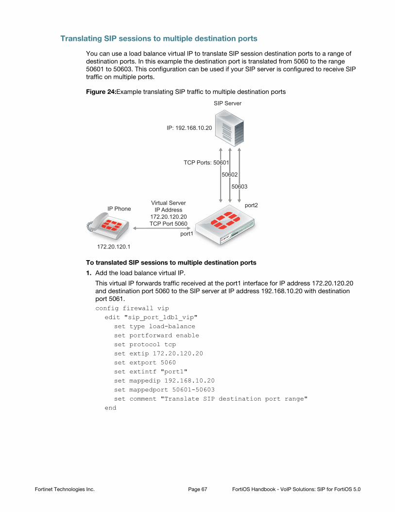
Translating SIP sessions to multiple destination ports
You can use a load balance virtual IP to translate SIP session destination ports to a range of
destination ports. In this example the destination port is translated from 5060 to the range
50601 to 50603. This configuration can be used if your SIP server is configured to receive SIP
traffic on multiple ports.
Figure 24:Example translating SIP traffic to multiple destination ports
To translated SIP sessions to multiple destination ports
1. Add the load balance virtual IP.
This virtual IP forwards traffic received at the port1 interface for IP address 172.20.120.20
and destination port 5060 to the SIP server at IP address 192.168.10.20 with destination
port 5061.
config firewall vipedit "sip_port_ldbl_vip"
set type load-balanceset portforward enableset protocol tcpset extip 172.20.120.20set extport 5060set extintf "port1"set mappedip 192.168.10.20set mappedport 50601-50603set comment "Translate SIP destination port range"
end
Virtual ServerIP Address
172.20.120.20TCP Port 5060
172.20.120.1
SIP Server
IP Phone
port1
port2
IP: 192.168.10.20
50602
50603
TCP Ports: 50601
t11
p
Fortinet Technologies Inc. Page 67 FortiOS Handbook - VoIP Solutions: SIP for FortiOS 5.0
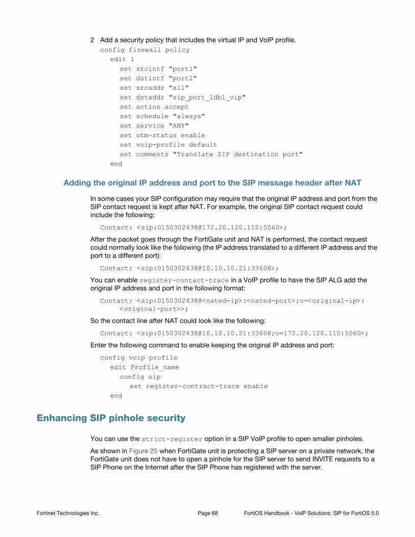
2 Add a security policy that includes the virtual IP and VoIP profile.
config firewall policyedit 1
set srcintf "port1"set dstintf "port2"set srcaddr "all"set dstaddr "sip_port_ldbl_vip"set action acceptset schedule "always"set service "ANY"set utm-status enableset voip-profile defaultset comments "Translate SIP destination port"
end
Adding the original IP address and port to the SIP message header after NAT
In some cases your SIP configuration may require that the original IP address and port from the
SIP contact request is kept after NAT. For example, the original SIP contact request could
include the following:
Contact: <sip:[email protected]:5060>;
After the packet goes through the FortiGate unit and NAT is performed, the contact request
could normally look like the following (the IP address translated to a different IP address and the
port to a different port):
Contact: <sip:[email protected]:33608>;
You can enable register-contact-trace in a VoIP profile to have the SIP ALG add the
original IP address and port in the following format:
Contact: <sip:0150302438@<nated-ip>:<nated-port>;o=<original-ip>: <original-port>>;
So the contact line after NAT could look like the following:
Contact: <sip:[email protected]:33608;o=172.20.120.110:5060>;
Enter the following command to enable keeping the original IP address and port:
config voip profileedit Profile_name
config sipset register-contract-trace enable
end
Enhancing SIP pinhole security
You can use the strict-register option in a SIP VoIP profile to open smaller pinholes.
As shown in Figure 25 when FortiGate unit is protecting a SIP server on a private network, the
FortiGate unit does not have to open a pinhole for the SIP server to send INVITE requests to a
SIP Phone on the Internet after the SIP Phone has registered with the server.
Fortinet Technologies Inc. Page 68 FortiOS Handbook - VoIP Solutions: SIP for FortiOS 5.0
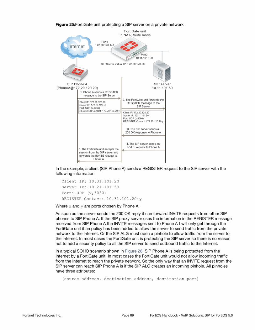
Figure 25:FortiGate unit protecting a SIP server on a private network
In the example, a client (SIP Phone A) sends a REGISTER request to the SIP server with the
following information:
Client IP: 10.31.101.20Server IP: 10.21.101.50Port: UDP (x,5060)REGISTER Contact: 10.31.101.20:y
Where x and y are ports chosen by Phone A.
As soon as the server sends the 200 OK reply it can forward INVITE requests from other SIP
phones to SIP Phone A. If the SIP proxy server uses the information in the REGISTER message
received from SIP Phone A the INVITE messages sent to Phone A f will only get through the
FortiGate unit if an policy has been added to allow the server to send traffic from the private
network to the Internet. Or the SIP ALG must open a pinhole to allow traffic from the server to
the Internet. In most cases the FortiGate unit is protecting the SIP server so there is no reason
not to add a security policy to all the SIP server to send outbound traffic to the Internet.
In a typical SOHO scenario shown in Figure 26, SIP Phone A is being protected from the
Internet by a FortiGate unit. In most cases the FortiGate unit would not allow incoming traffic
from the Internet to reach the private network. So the only way that an INVITE request from the
SIP server can reach SIP Phone A is if the SIP ALG creates an incoming pinhole. All pinholes
have three attributes:
(source address, destination address, destination port)
Port210.11.101.100
SIP Server Virtual IP: 172.20.120.50
Port1172.20.120.141
FortiGate unitIn NAT/Route mode
1. Phone A sends a REGSTERmessage to the SIP Server
SIP server10.11.101.50
SIP Phone A([email protected])
2. The FortiGate unit forwards theREGSTER message to the
SIP Server
3. The SIP server sends a200 OK response to Phone A
4. The SIP server sends anINVITE request to Phone A
Client IP: 172.20.120.20Server IP: 172.20.120.50Port: UDP (x,5060)REGISTER Contact: 172.20.120.20:y
Client IP: 172.20.120.20Server IP: 10.11.101.50Port: UDP (x,5060)REGISTER Contact: 172.20.120.20:y
5. The FortiGate unit accepts thesession from the SIP server andforwards the INVITE request to
Phone A
PPPoPort211010.11.101.10
0.141
Fortinet Technologies Inc. Page 69 FortiOS Handbook - VoIP Solutions: SIP for FortiOS 5.0
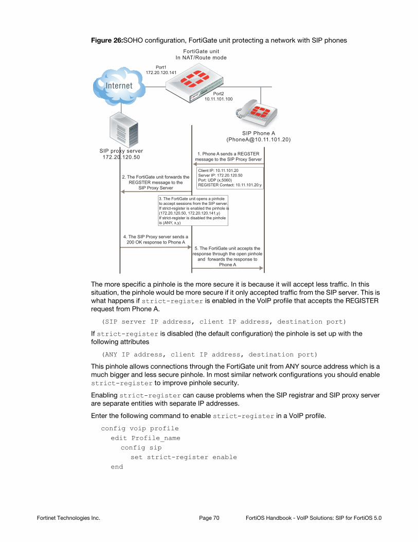
Figure 26:SOHO configuration, FortiGate unit protecting a network with SIP phones
The more specific a pinhole is the more secure it is because it will accept less traffic. In this
situation, the pinhole would be more secure if it only accepted traffic from the SIP server. This is
what happens if strict-register is enabled in the VoIP profile that accepts the REGISTER
request from Phone A.
(SIP server IP address, client IP address, destination port)
If strict-register is disabled (the default configuration) the pinhole is set up with the
following attributes
(ANY IP address, client IP address, destination port)
This pinhole allows connections through the FortiGate unit from ANY source address which is a
much bigger and less secure pinhole. In most similar network configurations you should enable
strict-register to improve pinhole security.
Enabling strict-register can cause problems when the SIP registrar and SIP proxy server
are separate entities with separate IP addresses.
Enter the following command to enable strict-register in a VoIP profile.
config voip profileedit Profile_name
config sipset strict-register enable
end
Port210.11.101.100
Port1172.20.120.141
FortiGate unitIn NAT/Route mode
1. Phone A sends a REGSTERmessage to the SIP Proxy Server
SIP proxy server172.20.120.50
SIP Phone A([email protected])
2. The FortiGate unit forwards theREGSTER message to the
SIP Proxy Server
4. The SIP Proxy server sends a200 OK response to Phone A
5. The FortiGate unit accepts theresponse through the open pinhole
and forwards the response toPhone A
Client IP: 10.11.101.20Server IP: 172.20.120.50Port: UDP (x,5060)REGISTER Contact: 10.11.101.20:y
3. The FortiGate unit opens a pinholeto accept sessions from the SIP server.If strict-register is enabled the pinhole is(172.20.120.50, 172.20.120.141,y)If strict-register is disabled the pinholeis (ANY, x,y)
Fortinet Technologies Inc. Page 70 FortiOS Handbook - VoIP Solutions: SIP for FortiOS 5.0
Hosted NAT traversal
With the increase in the use of VoIP and other media traffic over the Internet, service provider
network administrators must defend their networks from threats while allowing voice and
multimedia traffic to flow transparently between users and servers and among users. A common
scenario could involve providing SIP VoIP services for customers with SIP phones installed
behind NAT devices that are not SIP aware. NAT devices that are not SIP aware cannot translate
IP addresses in SIP headers and SDP lines in SIP packets but can and do perform source NAT
on the source or addresses of the packets. In this scenario the user’s SIP phones would
communicate with a SIP proxy server to set up calls between SIP phones. Once the calls are set
up RTP packets would be communicated directly between the phones through each user’s NAT
device.
The problem with this configuration is that the SIP headers and SDP lines in the SIP packets
sent from the phones and received by the SIP proxy server would contain the private network
addresses of the VoIP phones that would not be routable on the service provider network or on
the Internet. One solution could be to for each customer to install and configure SIP aware NAT
devices. If this is not possible, another solution requires implement hosted NAT traversal.
In a hosted NAT traversal (HNT) configuration (for example, see Figure 27), a FortiGate unit is
installed between the NAT device and the SIP proxy server and configured with a VoIP profile
that enables SIP hosted NAT traversal. Security policies that include the VoIP profile also
support destination NAT using a firewall virtual IP. When the SIP phones connect to the SIP
server IP address the security policy accepts the SIP packets, the virtual IP translates the
destination addresses of the packets to the SIP server IP address, and the SIP ALG NAT
traversal configuration translates the source IP addresses on the SIP headers and SDP lines to
the source address of the SIP packets (which would be the external IP address of the NAT
devices). The SIP server then sees the SIP phone IP address as the external IP address of the
NAT device. As a result SIP and RTP media sessions are established using the external IP
addresses of the NAT devices instead of the actual IP addresses of the SIP phones.
Figure 27:FortiGate SIP Hosted NAT Traversal configuration
Fortinet Technologies Inc. Page 71 FortiOS Handbook - VoIP Solutions: SIP for FortiOS 5.0
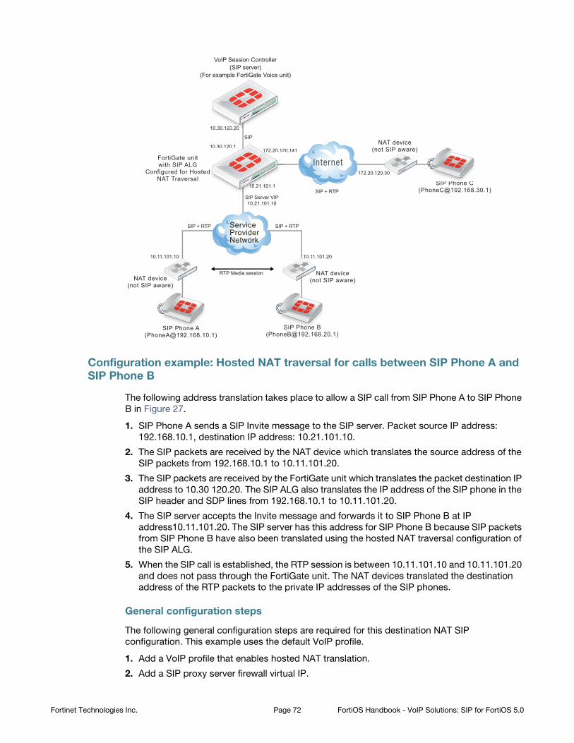
Configuration example: Hosted NAT traversal for calls between SIP Phone A and SIP Phone B
The following address translation takes place to allow a SIP call from SIP Phone A to SIP Phone
B in Figure 27.
1. SIP Phone A sends a SIP Invite message to the SIP server. Packet source IP address:
192.168.10.1, destination IP address: 10.21.101.10.
2. The SIP packets are received by the NAT device which translates the source address of the
SIP packets from 192.168.10.1 to 10.11.101.20.
3. The SIP packets are received by the FortiGate unit which translates the packet destination IP
address to 10.30 120.20. The SIP ALG also translates the IP address of the SIP phone in the
SIP header and SDP lines from 192.168.10.1 to 10.11.101.20.
4. The SIP server accepts the Invite message and forwards it to SIP Phone B at IP
address10.11.101.20. The SIP server has this address for SIP Phone B because SIP packets
from SIP Phone B have also been translated using the hosted NAT traversal configuration of
the SIP ALG.
5. When the SIP call is established, the RTP session is between 10.11.101.10 and 10.11.101.20
and does not pass through the FortiGate unit. The NAT devices translated the destination
address of the RTP packets to the private IP addresses of the SIP phones.
General configuration steps
The following general configuration steps are required for this destination NAT SIP
configuration. This example uses the default VoIP profile.
1. Add a VoIP profile that enables hosted NAT translation.
2. Add a SIP proxy server firewall virtual IP.
FortiGate unitwith SIP ALG
Configured for HostedNAT Traversal
NAT device(not SIP aware)
NAT device(not SIP aware)
NAT device(not SIP aware)
SIP Phone A([email protected])
SIP Phone B([email protected])
SIP Phone C([email protected])
SIP
SIP + RTP SIP + RTP
SIP + RTP
10.11.101.10 10.11.101.20
10.21.101.1
SIP Server VIP10.21.101.10
172.20.120.141
172.20.120.30
10.30.120.1
10.30.120.20
VoIP Session Controller(SIP server)
(For example FortiGate Voice unit)
RTP Media session
10 30 120 2000
edd
111010010.221.101.1
172.20.1210.30.120.1
SIP PhhP C
SIP PhPhhP BSIP PhP AA
ServiceProviderNetwork
Fortinet Technologies Inc. Page 72 FortiOS Handbook - VoIP Solutions: SIP for FortiOS 5.0
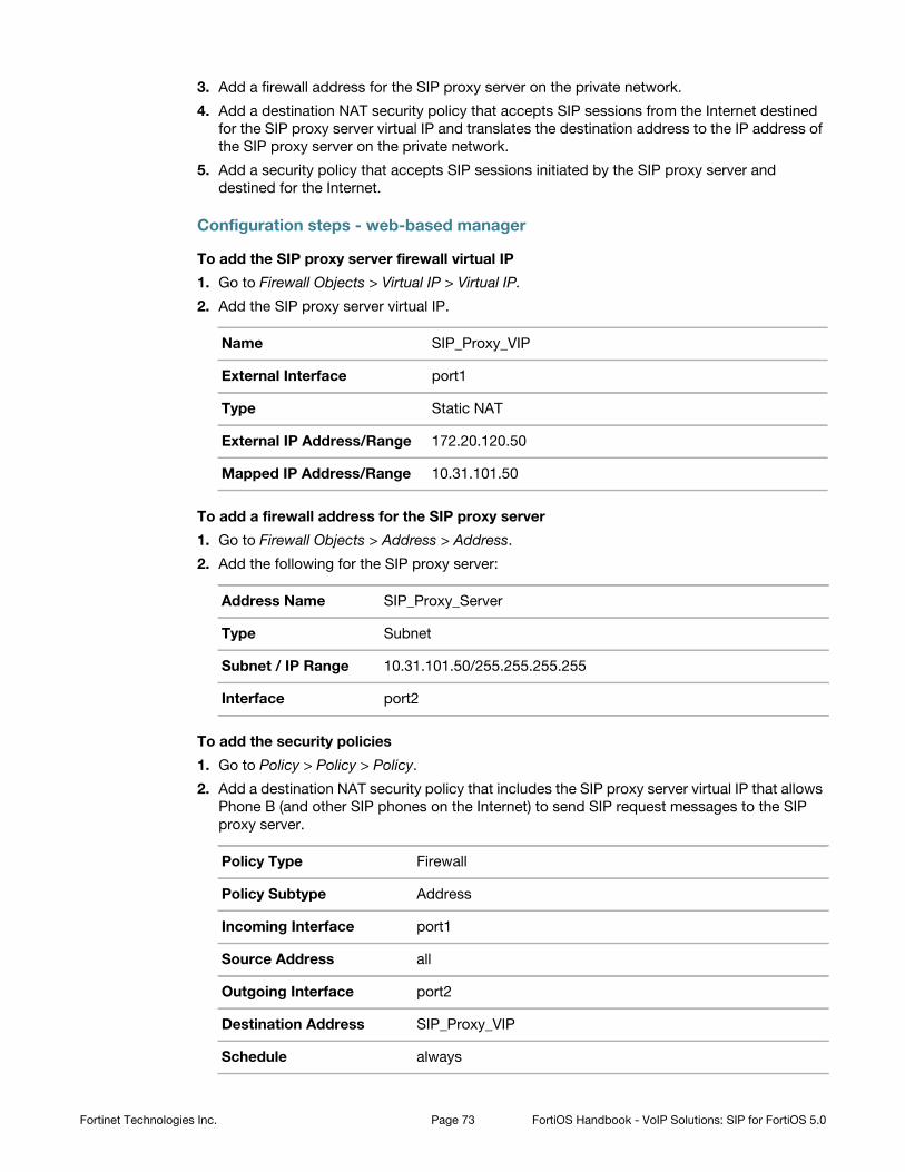
3. Add a firewall address for the SIP proxy server on the private network.
4. Add a destination NAT security policy that accepts SIP sessions from the Internet destined
for the SIP proxy server virtual IP and translates the destination address to the IP address of
the SIP proxy server on the private network.
5. Add a security policy that accepts SIP sessions initiated by the SIP proxy server and
destined for the Internet.
Configuration steps - web-based manager
To add the SIP proxy server firewall virtual IP
1. Go to Firewall Objects > Virtual IP > Virtual IP.
2. Add the SIP proxy server virtual IP.
To add a firewall address for the SIP proxy server
1. Go to Firewall Objects > Address > Address.
2. Add the following for the SIP proxy server:
To add the security policies
1. Go to Policy > Policy > Policy.
2. Add a destination NAT security policy that includes the SIP proxy server virtual IP that allows
Phone B (and other SIP phones on the Internet) to send SIP request messages to the SIP
proxy server.
Name SIP_Proxy_VIP
External Interface port1
Type Static NAT
External IP Address/Range 172.20.120.50
Mapped IP Address/Range 10.31.101.50
Address Name SIP_Proxy_Server
Type Subnet
Subnet / IP Range 10.31.101.50/255.255.255.255
Interface port2
Policy Type Firewall
Policy Subtype Address
Incoming Interface port1
Source Address all
Outgoing Interface port2
Destination Address SIP_Proxy_VIP
Schedule always
Fortinet Technologies Inc. Page 73 FortiOS Handbook - VoIP Solutions: SIP for FortiOS 5.0
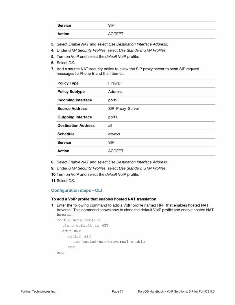
3. Select Enable NAT and select Use Destination Interface Address.
4. Under UTM Security Profiles, select Use Standard UTM Profiles.
5. Turn on VoIP and select the default VoIP profile.
6. Select OK.
7. Add a source NAT security policy to allow the SIP proxy server to send SIP request
messages to Phone B and the Internet:
8. Select Enable NAT and select Use Destination Interface Address.
9. Under UTM Security Profiles, select Use Standard UTM Profiles.
10.Turn on VoIP and select the default VoIP profile.
11.Select OK.
Configuration steps - CLI
To add a VoIP profile that enables hosted NAT translation
1 Enter the following command to add a VoIP profile named HNT that enables hosted NAT
traversal. This command shows how to clone the default VoIP profile and enable hosted NAT
traversal.
config voip profileclone default to HNTedit HNT
config sipset hosted-nat-traversal enable
endend
Service SIP
Action ACCEPT
Policy Type Firewall
Policy Subtype Address
Incoming Interface port2
Source Address SIP_Proxy_Server
Outgoing Interface port1
Destination Address all
Schedule always
Service SIP
Action ACCEPT
Fortinet Technologies Inc. Page 74 FortiOS Handbook - VoIP Solutions: SIP for FortiOS 5.0
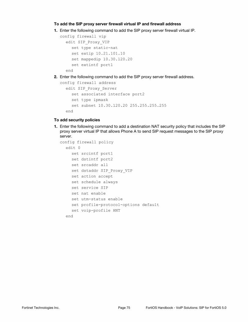
To add the SIP proxy server firewall virtual IP and firewall address
1. Enter the following command to add the SIP proxy server firewall virtual IP.
config firewall vipedit SIP_Proxy_VIP
set type static-natset extip 10.21.101.10set mappedip 10.30.120.20set extintf port1
end
2. Enter the following command to add the SIP proxy server firewall address.
config firewall addressedit SIP_Proxy_Server
set associated interface port2set type ipmaskset subnet 10.30.120.20 255.255.255.255
end
To add security policies
1. Enter the following command to add a destination NAT security policy that includes the SIP
proxy server virtual IP that allows Phone A to send SIP request messages to the SIP proxy
server.
config firewall policyedit 0
set srcintf port1set dstintf port2set srcaddr allset dstaddr SIP_Proxy_VIPset action acceptset schedule alwaysset service SIPset nat enableset utm-status enableset profile-protocol-options defaultset voip-profile HNT
end
Fortinet Technologies Inc. Page 75 FortiOS Handbook - VoIP Solutions: SIP for FortiOS 5.0
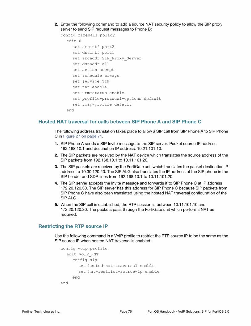
2. Enter the following command to add a source NAT security policy to allow the SIP proxy
server to send SIP request messages to Phone B:
config firewall policyedit 0
set srcintf port2set dstintf port1set srcaddr SIP_Proxy_Serverset dstaddr allset action acceptset schedule alwaysset service SIPset nat enableset utm-status enableset profile-protocol-options defaultset voip-profile default
end
Hosted NAT traversal for calls between SIP Phone A and SIP Phone C
The following address translation takes place to allow a SIP call from SIP Phone A to SIP Phone
C in Figure 27 on page 71.
1. SIP Phone A sends a SIP Invite message to the SIP server. Packet source IP address:
192.168.10.1 and destination IP address: 10.21.101.10.
2. The SIP packets are received by the NAT device which translates the source address of the
SIP packets from 192.168.10.1 to 10.11.101.20.
3. The SIP packets are received by the FortiGate unit which translates the packet destination IP
address to 10.30 120.20. The SIP ALG also translates the IP address of the SIP phone in the
SIP header and SDP lines from 192.168.10.1 to 10.11.101.20.
4. The SIP server accepts the Invite message and forwards it to SIP Phone C at IP address
172.20.120.30. The SIP server has this address for SIP Phone C because SIP packets from
SIP Phone C have also been translated using the hosted NAT traversal configuration of the
SIP ALG.
5. When the SIP call is established, the RTP session is between 10.11.101.10 and
172.20.120.30. The packets pass through the FortiGate unit which performs NAT as
required.
Restricting the RTP source IP
Use the following command in a VoIP profile to restrict the RTP source IP to be the same as the
SIP source IP when hosted NAT traversal is enabled.
config voip profileedit VoIP_HNT
config sipset hosted-nat-traversal enableset hnt-restrict-source-ip enable
endend
Fortinet Technologies Inc. Page 76 FortiOS Handbook - VoIP Solutions: SIP for FortiOS 5.0
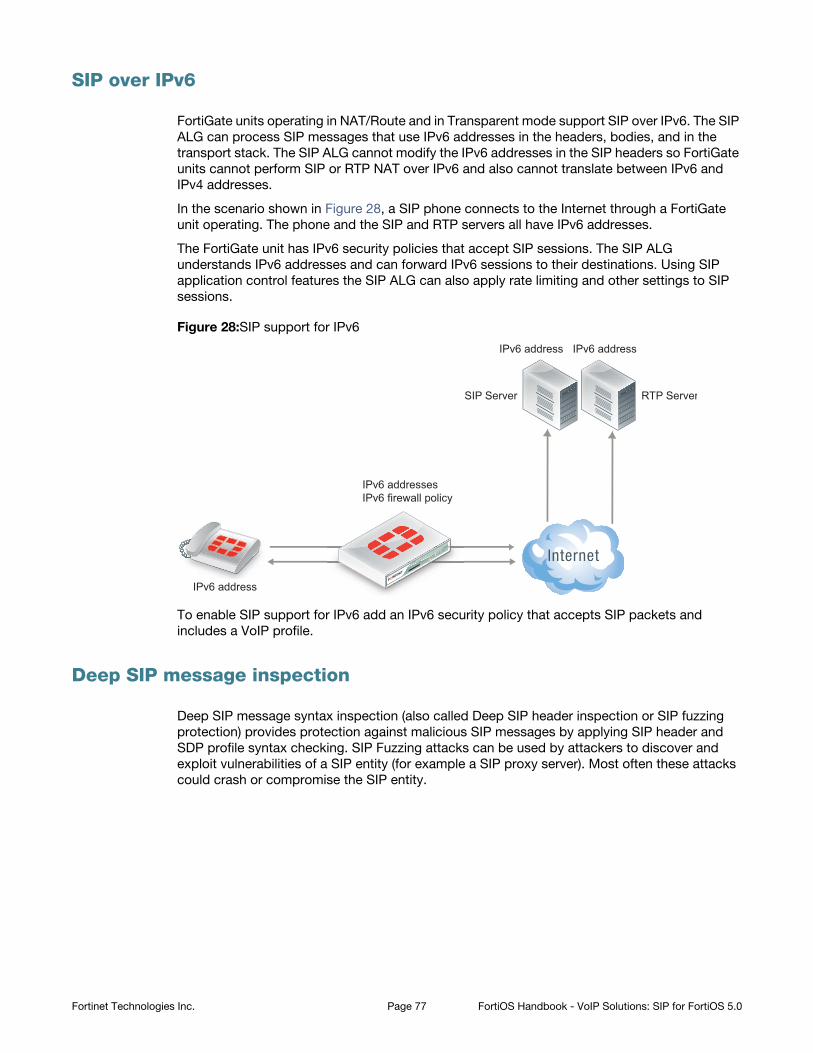
SIP over IPv6
FortiGate units operating in NAT/Route and in Transparent mode support SIP over IPv6. The SIP
ALG can process SIP messages that use IPv6 addresses in the headers, bodies, and in the
transport stack. The SIP ALG cannot modify the IPv6 addresses in the SIP headers so FortiGate
units cannot perform SIP or RTP NAT over IPv6 and also cannot translate between IPv6 and
IPv4 addresses.
In the scenario shown in Figure 28, a SIP phone connects to the Internet through a FortiGate
unit operating. The phone and the SIP and RTP servers all have IPv6 addresses.
The FortiGate unit has IPv6 security policies that accept SIP sessions. The SIP ALG
understands IPv6 addresses and can forward IPv6 sessions to their destinations. Using SIP
application control features the SIP ALG can also apply rate limiting and other settings to SIP
sessions.
Figure 28:SIP support for IPv6
To enable SIP support for IPv6 add an IPv6 security policy that accepts SIP packets and
includes a VoIP profile.
Deep SIP message inspection
Deep SIP message syntax inspection (also called Deep SIP header inspection or SIP fuzzing
protection) provides protection against malicious SIP messages by applying SIP header and
SDP profile syntax checking. SIP Fuzzing attacks can be used by attackers to discover and
exploit vulnerabilities of a SIP entity (for example a SIP proxy server). Most often these attacks
could crash or compromise the SIP entity.
IPv6 address
SIP Server
IPv6 addressesIPv6 firewall policy
RTP Server
IPv6 address IPv6 address
Fortinet Technologies Inc. Page 77 FortiOS Handbook - VoIP Solutions: SIP for FortiOS 5.0
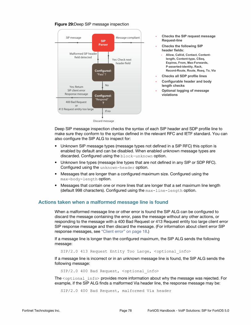
Figure 29:Deep SIP message inspection
Deep SIP message inspection checks the syntax of each SIP header and SDP profile line to
make sure they conform to the syntax defined in the relevant RFC and IETF standard. You can
also configure the SIP ALG to inspect for:
• Unknown SIP message types (message types not defined in a SIP RFC) this option is
enabled by default and can be disabled. When enabled unknown message types are
discarded. Configured using the block-unknown option.
• Unknown line types (message line types that are not defined in any SIP or SDP RFC).
Configured using the unknown-header option.
• Messages that are longer than a configured maximum size. Configured using the
max-body-length option.
• Messages that contain one or more lines that are longer that a set maximum line length
(default 998 characters). Configured using the max-line-length option.
Actions taken when a malformed message line is found
When a malformed message line or other error is found the SIP ALG can be configured to
discard the message containing the error, pass the message without any other actions, or
responding to the message with a 400 Bad Request or 413 Request entity too large client error
SIP response message and then discard the message. (For information about client error SIP
response messages, see “Client error” on page 18.)
If a message line is longer than the configured maximum, the SIP ALG sends the following
message:
SIP/2.0 413 Request Entity Too Large, <optional_info>
If a message line is incorrect or in an unknown message line is found, the SIP ALG sends the
following message:
SIP/2.0 400 Bad Request, <optional_info>
The <optional_info> provides more information about why the message was rejected. For
example, if the SIP ALG finds a malformed Via header line, the response message may be:
SIP/2.0 400 Bad Request, malformed Via header
FortiCarrier
ActiveBlade
SIP message
Malformed SIP header field detected
Yes: Check next header field
Yes: ReturnSIP client error
Response message
400 Bad Request or
413 Request entity too large
No
Discard message
Message compliant
• Checks the following SIP header fields:
• Checks the SIP request message Request-line
• Checks all SDP profile lines
• Allow, Call-id, Contact, Content-length, Content-type, CSeq,Expires, From, Max-Forwards,P-asserted-identity, Rack,Record-Route, Route, Rseq, To, Via
• Configurable header and body length checks
• Optional logging of message violations
SIP Parser
Configured:“Pass” ?
Configured:“Respond”
?
If no
Fortinet Technologies Inc. Page 78 FortiOS Handbook - VoIP Solutions: SIP for FortiOS 5.0
If the SIP ALG finds a malformed message line, and the action for this message line type is
discard, the message is discarded with no further checking or responses. If the action is pass,
the SIP ALG continues parsing the SIP message for more malformed message lines. If the
action is respond, the SIP ALG sends the SIP response message and discards the message
containing the malformed line with no further checking or response. If only malformed message
line types with action set to pass are found, the SIP ALG extracts as much information as
possible from the message (for example for NAT and opening pinholes, and forwards the
message to its destination).
If a SIP message containing a malformed line is discarded the SIP ALG will not use the
information in the message for call processing. This could result in the call being terminated. If a
malformed line in a SIP message includes information required for the SIP call that the SIP ALG
cannot interpret (for example, if an IP address required for SIP NAT is corrupted) the SIP ALG
may not be able to continue processing the call and it could be terminated. Discarded
messages are counted by SIP ALG static message counters.
Logging and statistics
To record a log message each time the SIP ALG finds a malformed header, enable logging SIP
violations in a VoIP profile. In all cases, when the SIP ALG finds an error the FortiGate unit
records a malformed header log message that contains information about the error. This
happens even if the action is set to pass.
If, because of recording log messages for deep message inspection, the CPU performance is
affected by a certain amount, the FortiGate unit records a critical log message about this event
and stops writing log messages for deep SIP message inspection.
The following information is recorded in malformed header messages:
• The type of message line in which the error was found.
• The content of the message line in which the error was found (it will be truncated if it makes
the log message too long)
• The column or character number in which the error was found (to make it easier to determine
what caused the error)
Deep SIP message inspection best practices
Because of the risks imposed by SIP header attacks or incorrect data being allowed and
because selecting drop or respond does not require more CPU overhead that pass you would
want to set all tests to drop or respond. However, in some cases malformed lines may be less of
a threat or risk. For example, the SDP i= does not usually contain information that is parsed by
any SIP device so a malformed i= line may not pose a threat.
You can also used the pre-defined VoIP profiles to apply different levels of deep message
inspection. The default VoIP profile sets all deep message inspection options to pass and the
strict VoIP profile sets all deep message inspection options to discard. From the CLI you can
use the clone command to copy these pre-defined VoIP profiles and then customize them for
your requirements.
Configuring deep SIP message inspection
You configure deep SIP message inspection in a VoIP profile. All deep SIP message inspection
options are available only from the CLI.
Fortinet Technologies Inc. Page 79 FortiOS Handbook - VoIP Solutions: SIP for FortiOS 5.0
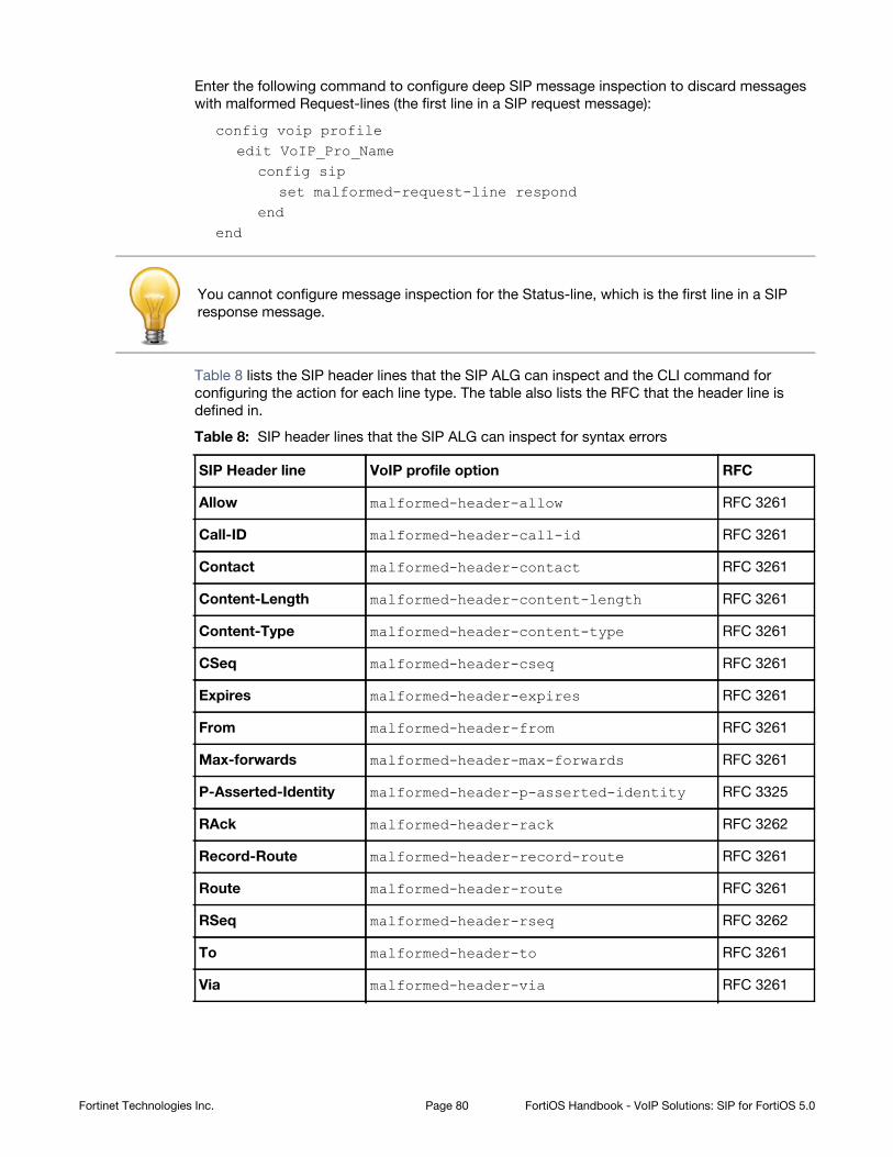
Enter the following command to configure deep SIP message inspection to discard messages
with malformed Request-lines (the first line in a SIP request message):
config voip profileedit VoIP_Pro_Name
config sipset malformed-request-line respond
endend
Table 8 lists the SIP header lines that the SIP ALG can inspect and the CLI command for
configuring the action for each line type. The table also lists the RFC that the header line is
defined in.
SIP Header line VoIP profile option RFC
Allow RFC 3261
Call-ID RFC 3261
Contact RFC 3261
Content-Length RFC 3261
Content-Type RFC 3261
CSeq RFC 3261
Expires RFC 3261
From RFC 3261
Max-forwards RFC 3261
P-Asserted-Identity RFC 3325
RAck RFC 3262
Record-Route RFC 3261
Route RFC 3261
RSeq RFC 3262
To RFC 3261
Via RFC 3261
You cannot configure message inspection for the Status-line, which is the first line in a SIP
response message.
Table 8: SIP header lines that the SIP ALG can inspect for syntax errors
malformed-header-allow
malformed-header-call-id
malformed-header-contact
malformed-header-content-length
malformed-header-content-type
malformed-header-cseq
malformed-header-expires
malformed-header-from
malformed-header-max-forwards
malformed-header-p-asserted-identity
malformed-header-rack
malformed-header-record-route
malformed-header-route
malformed-header-rseq
malformed-header-to
malformed-header-via
Fortinet Technologies Inc. Page 80 FortiOS Handbook - VoIP Solutions: SIP for FortiOS 5.0
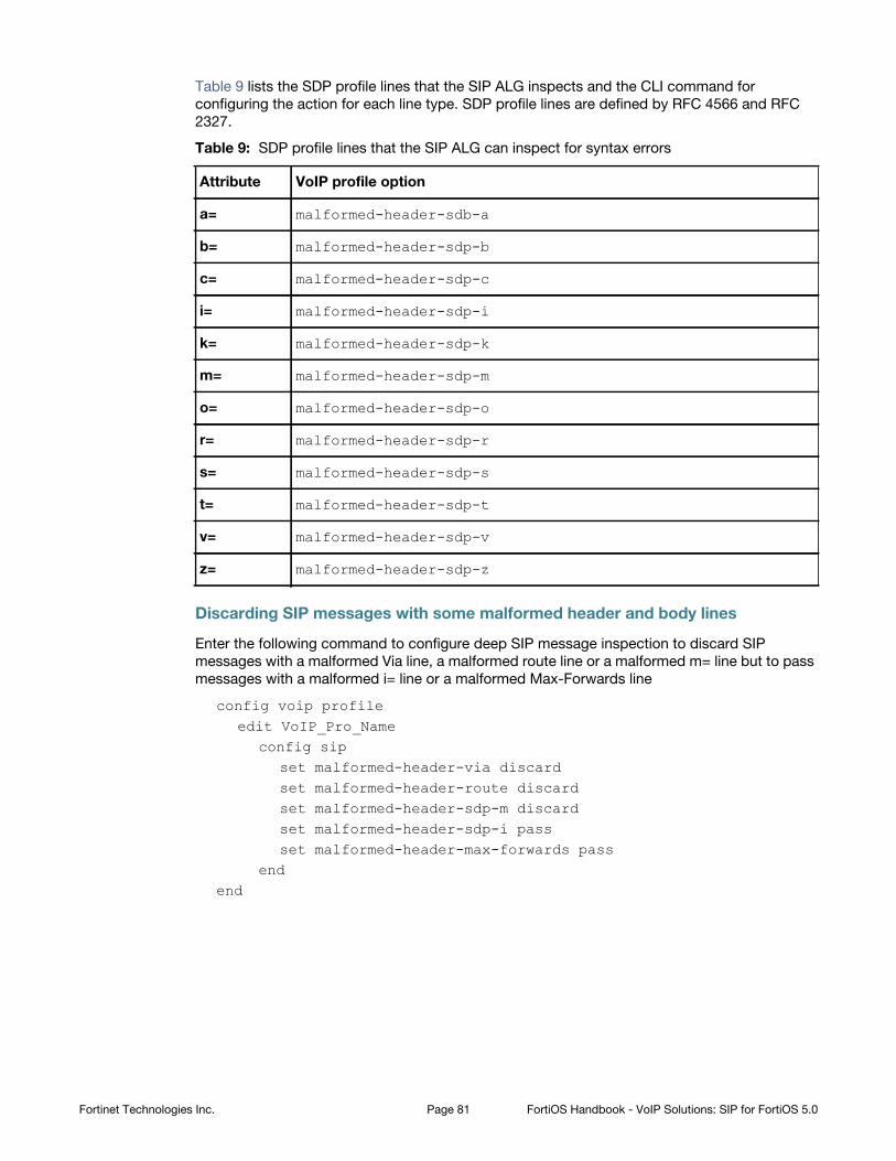
Table 9 lists the SDP profile lines that the SIP ALG inspects and the CLI command for
configuring the action for each line type. SDP profile lines are defined by RFC 4566 and RFC
2327.
Attribute VoIP profile option
a=
b=
c=
i=
k=
m=
o=
r=
s=
t=
v=
z=
Discarding SIP messages with some malformed header and body lines
Enter the following command to configure deep SIP message inspection to discard SIP
messages with a malformed Via line, a malformed route line or a malformed m= line but to pass
messages with a malformed i= line or a malformed Max-Forwards line
config voip profileedit VoIP_Pro_Name
config sipset malformed-header-via discardset malformed-header-route discardset malformed-header-sdp-m discardset malformed-header-sdp-i passset malformed-header-max-forwards pass
endend
Table 9: SDP profile lines that the SIP ALG can inspect for syntax errors
malformed-header-sdb-a
malformed-header-sdp-b
malformed-header-sdp-c
malformed-header-sdp-i
malformed-header-sdp-k
malformed-header-sdp-m
malformed-header-sdp-o
malformed-header-sdp-r
malformed-header-sdp-s
malformed-header-sdp-t
malformed-header-sdp-v
malformed-header-sdp-z
Fortinet Technologies Inc. Page 81 FortiOS Handbook - VoIP Solutions: SIP for FortiOS 5.0
Discarding SIP messages with an unknown SIP message type
Enter the following command to discard SIP messages with an unknown SIP message line type
as defined in all current SIP RFCs:
config voip profileedit VoIP_Pro_Name
config sipset unknown-header discard
endend
Discarding SIP messages that exceed a message size
Enter the following command to set the maximum size of a SIP message to 200 bytes.
Messages longer than 200 bytes are discarded.
config voip profileedit VoIP_Pro_Name
config sipset max-body-length 200
endend
The max-body-length option checks the value in the SIP Content-Length header line to
determine body length. The Content-Length can be larger than the actual size of a SIP message
if the SIP message content is split over more than one packet. SIP message sizes vary widely.
The size of a SIP message can also change with the addition of Via and Record-Route headers
as the message is transmitted between users and SIP servers.
Discarding SIP messages with lines longer than 500 characters
Enter the following command to set the length of a SIP message line to 500 characters and to
block messages that include lines with 500 or more characters:
config voip profileedit VoIP_Pro_Name
config sipset max-line-length 500set block-long-lines enable
endend
Blocking SIP request messages
You may want to block different types of SIP requests:
• to prevent SIP attacks using these messages.
• If your SIP server cannot process some SIP messages because of a temporary issue (for
example a bug that crashes or compromises the server when it receives a message of a
certain type).
• Your SIP implementation does not use certain message types.
When you enable message blocking for a message type in a VoIP profile, whenever a security
policy containing the VoIP profile accepts a SIP message of this type, the SIP ALG silently
discards the message and records a log message about the action.
Fortinet Technologies Inc. Page 82 FortiOS Handbook - VoIP Solutions: SIP for FortiOS 5.0
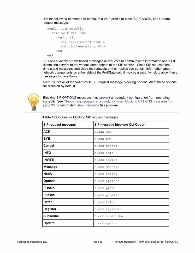
Use the following command to configure a VoIP profile to block SIP CANCEL and Update
request messages:
config voip profileedit VoIP_Pro_Name
config sipset block-cancel enableset block-update enable
endend
SIP uses a variety of text-based messages or requests to communicate information about SIP
clients and servers to the various components of the SIP network. Since SIP requests are
simple text messages and since the requests or their replies can contain information about
network components on either side of the FortiGate unit, it may be a security risk to allow these
messages to pass through.
Table 10 lists all of the VoIP profile SIP request message blocking options. All of these options
are disabled by default.
Blocking SIP OPTIONS messages may prevent a redundant configuration from operating
correctly. See “Supporting geographic redundancy when blocking OPTIONS messages” on
page 90 for information about resolving this problem.
Table 10:Options for blocking SIP request messages
SIP request message SIP message blocking CLI Option
ACK block-ack
BYE block-bye
Cancel block-cancel
INFO block-info
INVITE block-invite
Message block-message
Notify block-notify
Options block-options
PRACK block-prack
Publish block-publish
Refer block-refer
Register block-register
Subscribe block-subscribe
Update block-update
Fortinet Technologies Inc. Page 83 FortiOS Handbook - VoIP Solutions: SIP for FortiOS 5.0
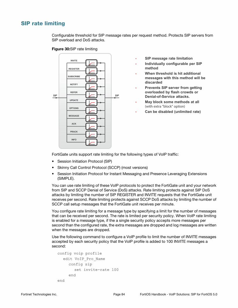
SIP rate limiting
Configurable threshold for SIP message rates per request method. Protects SIP servers from
SIP overload and DoS attacks.
Figure 30:SIP rate limiting
FortiGate units support rate limiting for the following types of VoIP traffic:
• Session Initiation Protocol (SIP)
• Skinny Call Control Protocol (SCCP) (most versions)
• Session Initiation Protocol for Instant Messaging and Presence Leveraging Extensions
(SIMPLE).
You can use rate limiting of these VoIP protocols to protect the FortiGate unit and your network
from SIP and SCCP Denial of Service (DoS) attacks. Rate limiting protects against SIP DoS
attacks by limiting the number of SIP REGISTER and INVITE requests that the FortiGate unit
receives per second. Rate limiting protects against SCCP DoS attacks by limiting the number of
SCCP call setup messages that the FortiGate unit receives per minute.
You configure rate limiting for a message type by specifying a limit for the number of messages
that can be received per second. The rate is limited per security policy. When VoIP rate limiting
is enabled for a message type, if the a single security policy accepts more messages per
second than the configured rate, the extra messages are dropped and log messages are written
when the messages are dropped.
Use the following command to configure a VoIP profile to limit the number of INVITE messages
accepted by each security policy that the VoIP profile is added to 100 INVITE messages a
second:
config voip profileedit VoIP_Pro_Name
config sipset invite-rate 100
endend
• SIP message rate limitation • Individually configurable per SIP
method• When threshold is hit additional
messages with this method will be discarded
• Prevents SIP server from getting overloaded by flash crowds or Denial-of-Service attacks.
• May block some methods at all (with extra “block” option)
• Can be disabled (unlimited rate)
SIP
INVITE
REGISTER
SUBSCRIBE
NOTIFY
REFER
UPDATE
OPTIONS
MESSAGE
ACK
PRACK
INFO
SIP
Fortinet Technologies Inc. Page 84 FortiOS Handbook - VoIP Solutions: SIP for FortiOS 5.0
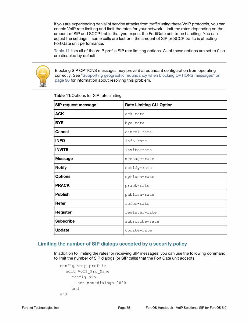
If you are experiencing denial of service attacks from traffic using these VoIP protocols, you can
enable VoIP rate limiting and limit the rates for your network. Limit the rates depending on the
amount of SIP and SCCP traffic that you expect the FortiGate unit to be handling. You can
adjust the settings if some calls are lost or if the amount of SIP or SCCP traffic is affecting
FortiGate unit performance.
Table 11 lists all of the VoIP profile SIP rate limiting options. All of these options are set to 0 so
are disabled by default.
SIP request message Rate Limiting CLI Option
ACK
BYE
Cancel
INFO
INVITE
Message
Notify
Options
PRACK
Publish
Refer
Register
Subscribe
Update
Limiting the number of SIP dialogs accepted by a security policy
In addition to limiting the rates for receiving SIP messages, you can use the following command
to limit the number of SIP dialogs (or SIP calls) that the FortiGate unit accepts.
config voip profileedit VoIP_Pro_Name
config sipset max-dialogs 2000
endend
Blocking SIP OPTIONS messages may prevent a redundant configuration from operating
correctly. See “Supporting geographic redundancy when blocking OPTIONS messages” on
page 90 for information about resolving this problem.
Table 11:Options for SIP rate limiting
ack-rate
bye-rate
cancel-rate
info-rate
invite-rate
message-rate
notify-rate
options-rate
prack-rate
publish-rate
refer-rate
register-rate
subscribe-rate
update-rate
Fortinet Technologies Inc. Page 85 FortiOS Handbook - VoIP Solutions: SIP for FortiOS 5.0
This command sets the maximum number of SIP dialogs that can be open for SIP sessions
accepted by any security policy that you add the VoIP profile to. The default setting of 0 does
not limit the number of dialogs. You can add a limit to control the number of open dialogs and
raise and lower it as required. You might want to limit the number of open dialogs for protection
against SIP-based attackers opening large numbers of SIP dialogs. Every dialog takes memory
and FortiGate CPU resources to process. Limiting the number of dialogs may improve the
overall performance of the FortiGate unit. Limiting the number of dialogs will not drop calls in
progress but may prevent new calls from connecting.
SIP logging and DLP archiving
You can enable SIP logging and logging of SIP violations, and SIP DLP archiving a VoIP profile.
To record SIP log messages you must also enable VoIP event logging in the FortiGate unit event
logging configuration.
To view SIP log messages go to Log&Report > Log Access > Event.
To view SIP DLP archive messages to go Log&Report > Archive Access > VoIP.
Use the following command enable SIP logging, SIP archiving, and logging of SIP violations in a
VoIP profile:
config voip profileedit VoIP_Pro_Name
config sipset log-call-summary enableset log-violations enable
endend
Inspecting SIP over SSL/TLS (secure SIP)
Some SIP phones and SIP servers can communicate using SSL or TLS to encrypt the SIP
signalling traffic. To allow SIP over SSL/TLS calls to pass through the FortiGate unit, the
encrypted signalling traffic has to be unencrypted and inspected. To do this, the FortiGate SIP
ALG intercepts and unencrypts and inspects the SIP packets. The packets are then
re-encrypted and forwarded to their destination.
Normally SIP over SSL/TLS uses port 5061. You can use the following command to change the
port that the FortiGate listens on for SIP over SSL/TLS sessions to port 5066:
config system settingsset sip-ssl-port 5066
end
The SIP ALG supports full mode SSL/TLS only. Traffic between SIP phones and the FortiGate
unit and between the FortiGate unit and the SIP server is always encrypted.
You enable SSL/TLS SIP communication by enabling SSL mode in a VoIP profile. You also need
to install the SIP server and client certificates on your FortiGate unit and add them to the SSL
configuration in the VoIP profile.
Fortinet Technologies Inc. Page 86 FortiOS Handbook - VoIP Solutions: SIP for FortiOS 5.0
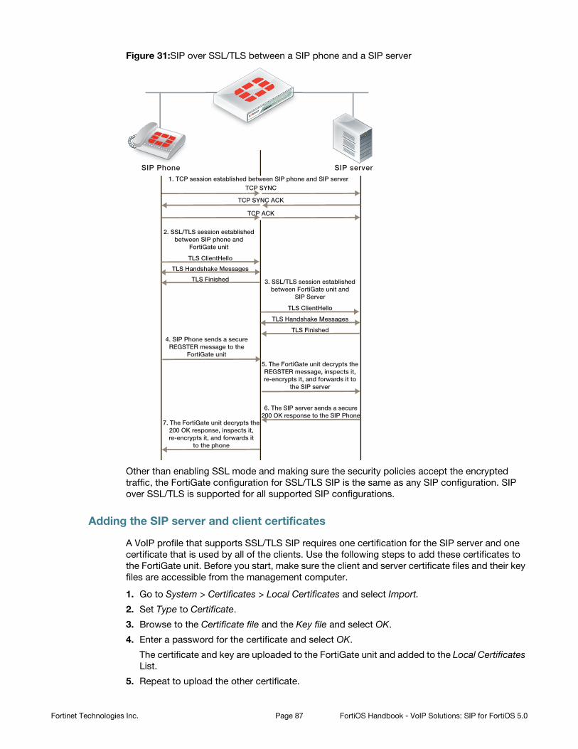
Figure 31:SIP over SSL/TLS between a SIP phone and a SIP server
Other than enabling SSL mode and making sure the security policies accept the encrypted
traffic, the FortiGate configuration for SSL/TLS SIP is the same as any SIP configuration. SIP
over SSL/TLS is supported for all supported SIP configurations.
Adding the SIP server and client certificates
A VoIP profile that supports SSL/TLS SIP requires one certification for the SIP server and one
certificate that is used by all of the clients. Use the following steps to add these certificates to
the FortiGate unit. Before you start, make sure the client and server certificate files and their key
files are accessible from the management computer.
1. Go to System > Certificates > Local Certificates and select Import.
2. Set Type to Certificate.
3. Browse to the Certificate file and the Key file and select OK.
4. Enter a password for the certificate and select OK.
The certificate and key are uploaded to the FortiGate unit and added to the Local Certificates
List.
5. Repeat to upload the other certificate.
1. TCP session established between SIP phone and SIP server
2. SSL/TLS session establishedbetween SIP phone and
FortiGate unit
4. SIP Phone sends a secureREGSTER message to the
FortiGate unit
TCP SYNC
TCP SYNC ACK
TCP ACK
TLS ClientHello
TLS Handshake Messages
TLS Finished
SIP serverSIP Phone
5. The FortiGate unit decrypts theREGSTER message, inspects it,re-encrypts it, and forwards it to
the SIP server
7. The FortiGate unit decrypts the200 OK response, inspects it,re-encrypts it, and forwards it
to the phone
6. The SIP server sends a secure200 OK response to the SIP Phone
3. SSL/TLS session establishedbetween FortiGate unit and
SIP Server
TLS ClientHello
TLS Handshake Messages
TLS Finished
Fortinet Technologies Inc. Page 87 FortiOS Handbook - VoIP Solutions: SIP for FortiOS 5.0
The certificates are added to the list of Local Certificates as the filenames you uploaded. You
can add comments to make it clear where its from and how it is intended to be used.
Adding SIP over SSL/TLS support to a VoIP profile
Use the following commands to add SIP over SSL/TLS support to the default VoIP profile. The
following command enables SSL mode and adds the client and server certificates and
passwords, the same ones you entered when you imported the certificates:
config voip profileedit default
config sipset ssl-mode fullset ssl-client-certificate "Client_cert"set ssl-server-certificate "Server_cert"set ssl-auth-client "check-server"set ssl-auth-server "check-server-group"
endend
Other SSL mode options are also available:
Enable to send empty fragments to avoid CBC IV attacks.
Compatible with SSL 3.0 and TLS 1.0 only. Default is
enable.
Control how the ALG responds when a client attempts to
renegotiate the SSL session. You can allow renegotiation or
block sessions when the client attempts to renegotiate. You
can also select secure to reject an SSL connection that
does not support RFC 5746 secure renegotiation indication.
Default is allow.
Select the relative strength of the algorithms that can be
selected. You can select high, the default, to allow only
AES or 3DES, medium, to allow AES, 3DES, or RC4 or low,
to allow AES, 3DES, RC4, or DES.
Select whether to allow, deny, or require perfect
forward secrecy (PFS). Default is allow.
Select the minimum level of SSL support to allow. The
default is ssl-3.0.
Select the maximum level of SSL support to allow. The
default is tls-1.1.
SIP and HA: session failover and geographic redundancy
FortiGate high availability supports SIP session failover (also called stateful failover) for
active-passive HA. To support SIP session failover, create a standard HA configuration and
select the Enable Session Pick-up option.
ssl-send-empty-frags {disable | enable}
ssl-client-renegotiation {allow | deny | secure}
ssl-algorithm {high | low | medium}
ssl-pfs {allow | deny | regqure}
ssl-min-version {ssl-3.0 | tls-1.0 | tls-1.1}
ssl-max-version {ssl-3.0 | tls-1.0 | tls-1.1}
Fortinet Technologies Inc. Page 88 FortiOS Handbook - VoIP Solutions: SIP for FortiOS 5.0
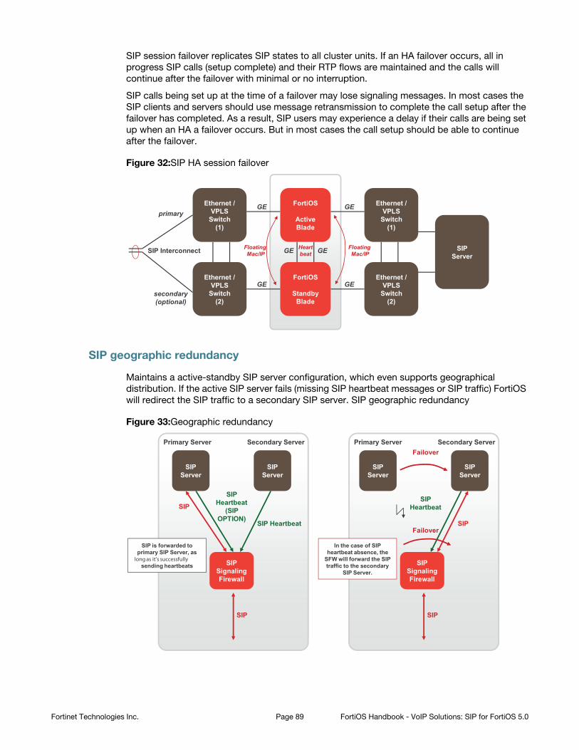
SIP session failover replicates SIP states to all cluster units. If an HA failover occurs, all in
progress SIP calls (setup complete) and their RTP flows are maintained and the calls will
continue after the failover with minimal or no interruption.
SIP calls being set up at the time of a failover may lose signaling messages. In most cases the
SIP clients and servers should use message retransmission to complete the call setup after the
failover has completed. As a result, SIP users may experience a delay if their calls are being set
up when an HA a failover occurs. But in most cases the call setup should be able to continue
after the failover.
Figure 32:SIP HA session failover
SIP geographic redundancy
Maintains a active-standby SIP server configuration, which even supports geographical
distribution. If the active SIP server fails (missing SIP heartbeat messages or SIP traffic) FortiOS
will redirect the SIP traffic to a secondary SIP server. SIP geographic redundancy
Figure 33:Geographic redundancy
SIPServer
ENET/VPLS
Switch(1)
ENET/VPLS
Switch(2)
ENET/VPLS
Switch(1)
ENET/VPLS
Switch(2)
FortiCarrier
ActiveBlade
FortiCarrier
StandbyBlade
SIP Interconnect
primary
secondary (optional)
GE
GE GE
GE
GEGE Heartbeat
FloatingMac/IP
FloatingMac/IP
Ethernet / VPLS
Switch(1)
Ethernet / VPLS
Switch(2)
Ethernet / VPLS
Switch(1)
Ethernet / VPLS
Switch(2)
SIPServer
FortiOS
ActiveBlade
FortiOS
StandbyBlade
SIPServer
SIPServer
Primary Server Secondary Server
SIP Heartbeat
SIP Heartbeat
(SIP OPTION)
SIP
SIP
SIP is forwarded to primary SIP Server, as
long as it’s successfully sending heartbeats
SIPServer
SIPServer
Primary Server Secondary Server
SIP Heartbeat
SIP
SIP
In the case of SIP heartbeat absence, the
SFW will forward the SIP traffic to the secondary
SIP Server.
Failover
Failover
SIPSignaling Firewall
SIPSignaling Firewall
SIPServer
SIPServer
SIPServer
SIPServer
Fortinet Technologies Inc. Page 89 FortiOS Handbook - VoIP Solutions: SIP for FortiOS 5.0
Supporting geographic redundancy when blocking OPTIONS messages
For some geographic redundant SIP configurations, the SIP servers may use SIP OPTIONS
messages as heartbeats to notify the FortiGate unit that they are still operating (or alive). This is
a kind of passive SIP monitoring mechanism where the FortiGate unit isn’t actively monitoring
the SIP servers and instead the FortiGate unit passively receives and analyzes OPTIONS
messages from the SIP servers.
If FortiGate units block SIP OPTIONS messages because block-options is enabled, the
configuration may fail to operate correctly because the OPTIONS messages are blocked by one
or more FortiGate units.
However, you can work around this problem by enabling the block-geo-red-options
application control list option. This option causes the FortiGate unit to refresh the local SIP
server status when it receives an OPTIONS message before dropping the message. The end
result is the heartbeat signals between geographically redundant SIP servers are maintained but
OPTIONS messages do not pass through the FortiGate unit.
Use the following command to block OPTIONS messages while still supporting geographic
redundancy:
config voip profileedit VoIP_Pro_Name
config sipset block-options disableset block-geo-red-options enable
endend
Support for RFC 2543-compliant branch parameters
RFC 3261 is the most recent SIP RFC, it obsoletes RFC 2543. However, some SIP
implementations may use RFC 2543-compliant SIP calls.
The rfc2543-branch VoIP profile option allows the FortiGate unit to support SIP calls that
include an RFC 2543-compliant branch parameter in the SIP Via header. This option also allows
FortiGate units to support SIP calls that include Via headers that are missing the branch
parameter.
config voip profileedit VoIP_Pro_Name
config sipset rfc2543-branch enable
endend
The block-options option setting overrides the block-geo-red-options option. If
block-options is enabled the FortiGate unit only blocks SIP OPTIONS messages and does
not refresh local SIP server status.
Fortinet Technologies Inc. Page 90 FortiOS Handbook - VoIP Solutions: SIP for FortiOS 5.0
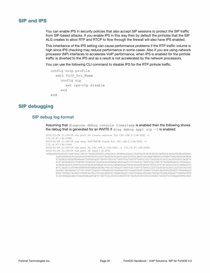
SIP and IPS
You can enable IPS in security policies that also accept SIP sessions to protect the SIP traffic
from SIP-based attacks. If you enable IPS in this way then by default the pinholes that the SIP
ALG creates to allow RTP and RTCP to flow through the firewall will also have IPS enabled.
This inheritance of the IPS setting can cause performance problems if the RTP traffic volume is
high since IPS checking may reduce performance in some cases. Also if you are using network
processor (NP) interfaces to accelerate VoIP performance, when IPS is enabled for the pinhole
traffic is diverted to the IPS and as a result is not accelerated by the network processors.
You can use the following CLI command to disable IPS for the RTP pinhole traffic.
config voip profileedit VoIP_Pro_Name
config sipset ips-rtp disable
endend
SIP debugging
SIP debug log format
Assuming that diagnose debug console timestamp is enabled then the following shows
the debug that is generated for an INVITE if diag debug appl sip -1 is enabled:
2010-01-04 21:39:59 sip port 26 locate session for 192.168.2.134:5061 ->172.16.67.192:50602010-01-04 21:39:59 sip sess 0x979df38 found for 192.168.2.134:5061 ->172.16.67.192:50602010-01-04 21:39:59 sip port 26 192.168.2.134:5061 -> 172.16.67.192:50602010-01-04 21:39:59 sip port 26 read [(0,515)(494e56495445207369703a73657276696365403139322e3136382e322e3130303a35303630205349502f322e300d0a566961
3a205349502f322e302f554450203132372e302e312e313a353036313b6272616e63683d7a39684734624b2d363832372d3632302d300d0a46726f6d3a2073697070203c7369703a73697070403132372e302e312e313a353036313e3b7461673d363832375349507054616730303632300d0a546f3a20737574203c7369703a73657276696365403139322e3136382e322e3130303a353036303e0d0a43616c6c2d49443a203632302d36383237403132372e302e312e310d0a435365713a203120494e564954450d0a436f6e746163743a207369703a73697070403132372e302e312e313a353036310d0a4d61782d466f7277617264733a2037300d0a5375626a6563743a20506572666f726d616e636520546573740d0a436f6e74656e742d547970653a206170706c69636174696f6e2f7364700d0a436f6e74656e742d4c656e6774683a20203132390d0a0d0a763d300d0a6f3d7573657231203533363535373635203233353336383736333720494e2049503420
Fortinet Technologies Inc. Page 91 FortiOS Handbook - VoIP Solutions: SIP for FortiOS 5.0
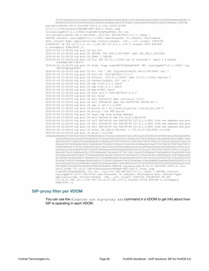
3132372e302e312e310d0a733d2d0d0a633d494e20495034203132372e302e312e310d0a743d3020300d0a6d3d617564696f2036303031205254502f41565020300d0a613d7274706d61703a302050434d552f383030300d0a)(INVITE
sip:[email protected]:5060 SIP/2.0..Via: SIP/2.0/UDP127.0.1.1:5061;branch=z9hG4bK-6827-620-0..From: sipp%lt;sip:[email protected]:5061>;tag=6827SIPpTag00620..To: sut%lt;sip:[email protected]:5060>..Call-ID: [email protected]: 1INVITE..Contact: sip:[email protected]:5061..Max-Forwards: 70..Subject: PerformanceTest..Content-Type: application/sdp..Content-Length: 129....v=0..o=user1 536557652353687637 IN IP4 127.0.1.1..s=-..c=IN IP4 127.0.1.1..t=0 0..m=audio 6001 RTP/AVP0..a=rtpmap:0 PCMU/8000..)]2010-01-04 21:39:59 sip port 26 len 5152010-01-04 21:39:59 sip port 26 INVITE '192.168.2.100:5060' addr 192.168.2.100:50602010-01-04 21:39:59 sip port 26 CSeq: 1 INVITE2010-01-04 21:39:59 sip port 26 Via: UDP 127.0.1.1:5061 len 14 received 0 rport 0 0 branch
'z9hG4bK-6827-620-0'2010-01-04 21:39:59 sip port 26 From: 'sipp ;tag=6827SIPpTag00620' URI 'sip:[email protected]:5061' tag
'6827SIPpTag00620'2010-01-04 21:39:59 sip port 26 To: 'sut ' URI 'sip:[email protected]:5060' tag ''2010-01-04 21:39:59 sip port 26 Call-ID: '[email protected]'2010-01-04 21:39:59 sip port 26 Contact: '127.0.1.1:5061' addr 127.0.1.1:5061 expires 02010-01-04 21:39:59 sip port 26 Content-Length: 129 len 32010-01-04 21:39:59 sip port 26 sdp o=127.0.1.1 len=92010-01-04 21:39:59 sip port 26 sdp c=127.0.1.1 len=92010-01-04 21:39:59 sip port 26 sdp m=6001 len=42010-01-04 21:39:59 sip port 26 find call 0 '[email protected]'2010-01-04 21:39:59 sip port 26 not found2010-01-04 21:39:59 sip port 26 call 0x97a47c0 open (collision (nil))2010-01-04 21:39:59 sip port 26 call 0x97a47c0 open txn 0x979f7f8 INVITE dir 02010-01-04 21:39:59 sip port 26 sdp i: 127.0.1.1:6001 2010-01-04 21:39:59 sip port 26 policy id 1 is_client_vs_policy 1 policy_dir_rev 02010-01-04 21:39:59 sip port 26 policy 1 not RTP policy2010-01-04 21:39:59 sip port 26 learn sdp from stream address2010-01-04 21:39:59 sip port 26 call 0x97a47c0 sdp 172.16.67.198:437222010-01-04 21:39:59 sip port 26 call 0x97a47c0 txn 0x979f7f8 127.0.1.1:5061 find new address and port2010-01-04 21:39:59 sip port 26 call 0x97a47c0 txn 0x979f7f8 127.0.1.1:5061 find new address and port2010-01-04 21:39:59 sip port 26 call 0x97a47c0 txn 0x979f7f8 127.0.1.1:5061 find new address and port2010-01-04 21:39:59 sip port 30 write 192.168.2.134:5061 -> 172.16.67.192:5060 (13,539)2010-01-04 21:39:59 sip port 30 write [(13,539)(494e56495445207369703a73657276696365403137322e31362e36372e3139323a35303630205349502f322e300d0a566961
3a205349502f322e302f554450203137322e31362e36372e3139383a35323036353b6272616e63683d7a39684734624b2d363832372d3632302d300d0a46726f6d3a2073697070203c7369703a73697070403137322e31362e36372e3139383a34333732343e3b7461673d363832375349507054616730303632300d0a546f3a20737574203c7369703a73657276696365403137322e31362e36372e3139323a353036303e0d0a43616c6c2d49443a203632302d36383237403132372e302e312e310d0a435365713a203120494e564954450d0a436f6e746163743a207369703a73697070403137322e31362e36372e3139383a34333732350d0a4d61782d466f7277617264733a2037300d0a5375626a6563743a20506572666f726d616e636520546573740d0a436f6e74656e742d547970653a206170706c69636174696f6e2f7364700d0a436f6e74656e742d4c656e6774683a20203133380d0a0d0a763d300d0a6f3d7573657231203533363535373635203233353336383736333720494e20495034203137322e31362e36372e3139380d0a733d2d0d0a633d494e20495034203137322e31362e36372e3139380d0a743d3020300d0a6d3d617564696f203433373232205254502f41565020300d0a613d7274706d61703a302050434d552f383030300d0a)(INVITE sip:[email protected]:5060 SIP/2.0..Via: SIP/2.0/UDP 172.16.67.198:52065;branch=z9hG4bK-6827-620-0..From: sipp ;tag=6827SIPpTag00620..To: sut ..Call-ID: [email protected]: 1 INVITE..Contact: sip:[email protected]:43725..Max-Forwards: 70..Subject: Performance Test..Content-Type: application/sdp..Content-Length: 138....v=0..o=user1 53655765 2353687637 IN IP4 172.16.67.198..s=-..c=IN IP4 172.16.67.198..t=0 0..m=audio 43722 RTP/AVP 0..a=rtpmap:0 PCMU/8000..)]
SIP-proxy filter per VDOM
You can use the diagnose sys sip-proxy xxx command in a VDOM to get info about how
SIP is operating in each VDOM.
Fortinet Technologies Inc. Page 92 FortiOS Handbook - VoIP Solutions: SIP for FortiOS 5.0
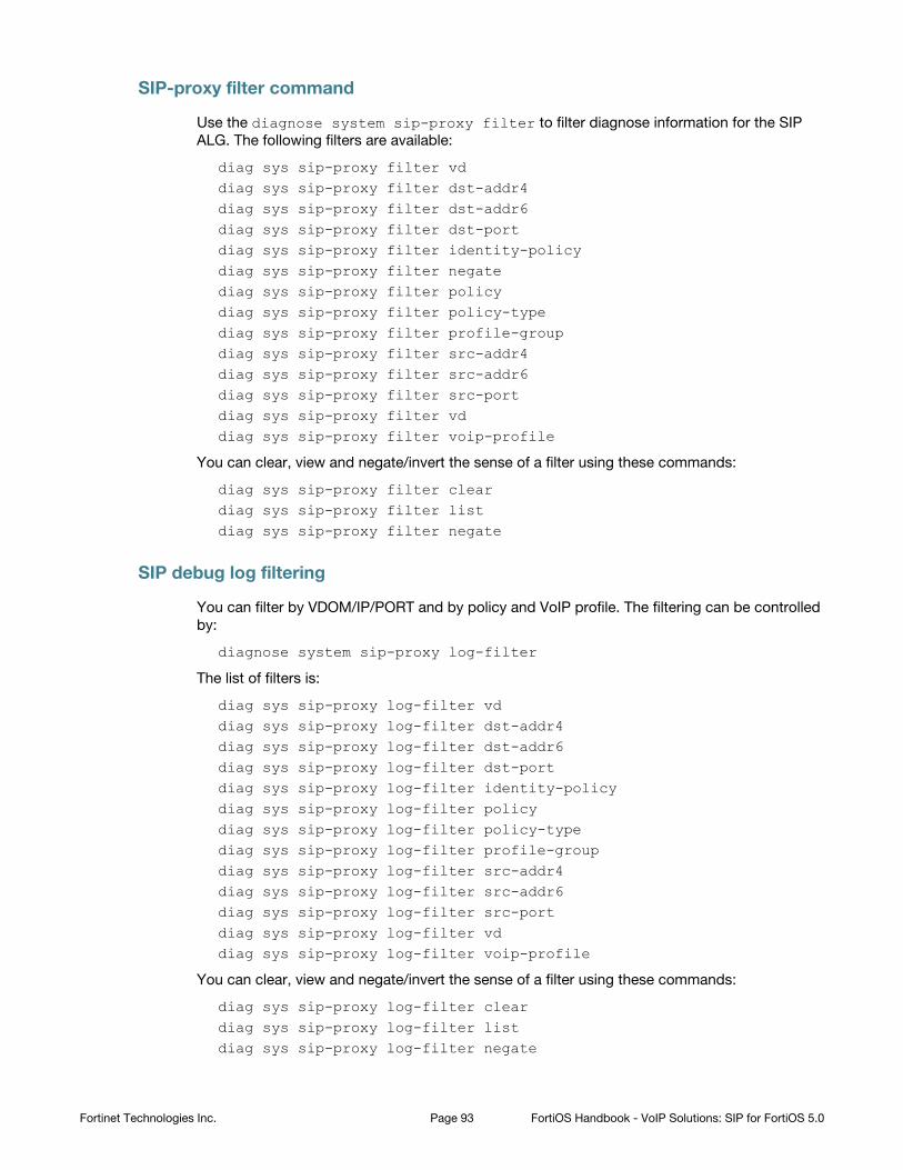
SIP-proxy filter command
Use the diagnose system sip-proxy filter to filter diagnose information for the SIP
ALG. The following filters are available:
diag sys sip-proxy filter vddiag sys sip-proxy filter dst-addr4diag sys sip-proxy filter dst-addr6diag sys sip-proxy filter dst-portdiag sys sip-proxy filter identity-policydiag sys sip-proxy filter negatediag sys sip-proxy filter policydiag sys sip-proxy filter policy-typediag sys sip-proxy filter profile-groupdiag sys sip-proxy filter src-addr4diag sys sip-proxy filter src-addr6diag sys sip-proxy filter src-portdiag sys sip-proxy filter vddiag sys sip-proxy filter voip-profile
You can clear, view and negate/invert the sense of a filter using these commands:
diag sys sip-proxy filter cleardiag sys sip-proxy filter listdiag sys sip-proxy filter negate
SIP debug log filtering
You can filter by VDOM/IP/PORT and by policy and VoIP profile. The filtering can be controlled
by:
diagnose system sip-proxy log-filter
The list of filters is:
diag sys sip-proxy log-filter vddiag sys sip-proxy log-filter dst-addr4diag sys sip-proxy log-filter dst-addr6diag sys sip-proxy log-filter dst-portdiag sys sip-proxy log-filter identity-policydiag sys sip-proxy log-filter policydiag sys sip-proxy log-filter policy-typediag sys sip-proxy log-filter profile-groupdiag sys sip-proxy log-filter src-addr4diag sys sip-proxy log-filter src-addr6diag sys sip-proxy log-filter src-portdiag sys sip-proxy log-filter vddiag sys sip-proxy log-filter voip-profile
You can clear, view and negate/invert the sense of a filter using these commands:
diag sys sip-proxy log-filter cleardiag sys sip-proxy log-filter listdiag sys sip-proxy log-filter negate
Fortinet Technologies Inc. Page 93 FortiOS Handbook - VoIP Solutions: SIP for FortiOS 5.0

SIP debug setting
Control of the SIP debug output is governed by the following command
diagnose debug application sip <debug_level_int>
Where the <debug_level_int> is a bitmask and the individual values determine whether the
listed items are logged or not. The <debug_level_int> can be
1 - configuration changes. Mainly addition/deletion/modification of virtual domains.
2 - (TCP) connection accepts or connects, redirect creation
4 - create or delete a session
16 - any IO read or write
32 - an ASCII dump of all data read or written
64 - Include HEX dump in the above output
128 - any activity related to the use of the FortiCarrier dynamic profile feature to determine the
correct profile-group to use
256 - log summary of interesting fields in a SIP call
1024 - any activity related to SIP geo-redundancy.
2048 - any activity related to HA syncing of SIP calls.
Display SIP rate-limit data
You can use the diagnose sys sip-proxy meters command to display SIP rate limiting
data.
Fortinet Technologies Inc. Page 94 FortiOS Handbook - VoIP Solutions: SIP for FortiOS 5.0
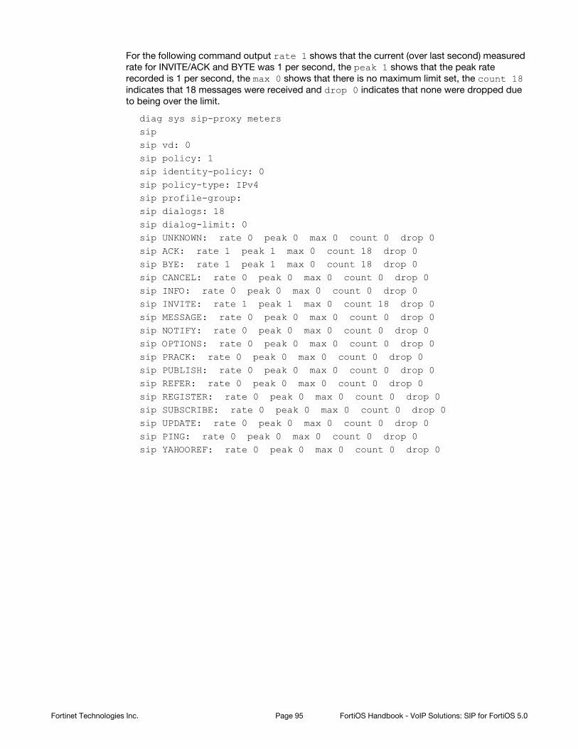
For the following command output rate 1 shows that the current (over last second) measured
rate for INVITE/ACK and BYTE was 1 per second, the peak 1 shows that the peak rate
recorded is 1 per second, the max 0 shows that there is no maximum limit set, the count 18
indicates that 18 messages were received and drop 0 indicates that none were dropped due
to being over the limit.
diag sys sip-proxy meterssip sip vd: 0sip policy: 1sip identity-policy: 0sip policy-type: IPv4sip profile-group: sip dialogs: 18sip dialog-limit: 0sip UNKNOWN: rate 0 peak 0 max 0 count 0 drop 0sip ACK: rate 1 peak 1 max 0 count 18 drop 0sip BYE: rate 1 peak 1 max 0 count 18 drop 0sip CANCEL: rate 0 peak 0 max 0 count 0 drop 0sip INFO: rate 0 peak 0 max 0 count 0 drop 0sip INVITE: rate 1 peak 1 max 0 count 18 drop 0sip MESSAGE: rate 0 peak 0 max 0 count 0 drop 0sip NOTIFY: rate 0 peak 0 max 0 count 0 drop 0sip OPTIONS: rate 0 peak 0 max 0 count 0 drop 0sip PRACK: rate 0 peak 0 max 0 count 0 drop 0sip PUBLISH: rate 0 peak 0 max 0 count 0 drop 0sip REFER: rate 0 peak 0 max 0 count 0 drop 0sip REGISTER: rate 0 peak 0 max 0 count 0 drop 0sip SUBSCRIBE: rate 0 peak 0 max 0 count 0 drop 0sip UPDATE: rate 0 peak 0 max 0 count 0 drop 0sip PING: rate 0 peak 0 max 0 count 0 drop 0sip YAHOOREF: rate 0 peak 0 max 0 count 0 drop 0
Fortinet Technologies Inc. Page 95 FortiOS Handbook - VoIP Solutions: SIP for FortiOS 5.0
Index
A
ALGchanging the port numbers that the SIP ALG listens
on 35
B
block 82
bodySIP message 9
branch 90
C
call-keepalive 38
contact-fixup 65
Content-LengthSIP header 82
D
deep SIP message inspection 77
defaultVoIP profile 34
destination NATSIP 61
diagnose sys sip 30, 36
diagnose sys sip debug-mask 30
diagnose sys sip dialog 30
diagnose sys sip mapping list 30
diagnose sys sip status 30
diagnose sys sip-proxy calls 35
diagnose sys sip-proxy filter 35
diagnose sys sip-proxy log-filter 35
diagnose sys sip-proxy meters 35
diagnose sys sip-proxy stats 36
dialogSIP 8, 14
DoS sensorSCCP 84SIP 84
dynamic IP poolSIP 62
F
fieldSIP 19
finalSIP response message 17
FortiFoneSIP phone 9
fuzzing protectionSIP 77
G
gui-voip-profile 34
H
HASIP session failover 88
hardware accelerationRTP 16
headerSIP 19SIP messages 9
HNT 71
hnt-restrict-source-ip 76
hosted NAT traversalSee HNT 71
hosted-nat-traversal 74
I
inactivity timeoutSIP session 37
informationalSIP response message 17
inspection without address translationSIP 12, 33
IP address conservationNAT 63
IP poolSIP 62
IPS 91disabling for pinholes 91
ips-rtp 91
IPv6SIP 77
L
limitingnumber of SIP dialogs 85
location serverSIP 11
M
malformed-request-line 80
max-body-length 82
max-dialogs 85
messageSIP 14
message lengthSIP 82
message request-lineSIP 19
message start lineSIP 19
Page 96
message status-lineSIP 19
N
NATSDP 65SIP ALG IP address conservation 64SIP ALG NAT tracing 64SIP contact headers 64SIP session helper NAT tracing 64with IP address conservation 63
nat-trace 64
no-sdp-fixup 65
P
pinholedisabling IPS 91more secure 68RTP 9, 13SIP 9, 13smaller 68strict-register 68
port numberchanging the port numbers that the SIP ALG listens
on 35changing the port numbers that the SIP session
helper listens on 27
PRACKSIP message 9, 17
preserve-override 64
profileVoIP 34
provisionalSIP response message 17
provisional response acknowledgementSIP message 9, 17
provisional-invite-expiry-time 39
proxy serverSIP 10
R
rate limitnumber of SIP dialogs 85
rate limitingSCCP 84SIMPLE 84SIP 84
Real Time Control Protocol 39
Real Time Protocol 51
redirect serverSIP 10
register-contact-trace 68
registrarSIP 11
requestSIP 8
request messages 16
Request-linedeep SIP message checking 80
request-lineSIP 19
responseSIP 8
RFCSIP 9
RFC 2543 90
RTCP 9, 39
RTP 9, 51, 61hardware acceleration 16pinhole 9, 13
S
SCCPDoS sensor 84protection profile 84rate limiting 84VoIP profile 33
SDP 9, 15, 21NAT 65session profile 21
session description protocolSee SDP 21
session failoverSIP 88
session helperchanging the port numbers that the SIP session
helper listens on 27disabling the SIP session helper 25enabling the SIP session helper 25
Session Initiation Protocol for Instant Messaging and Presence Leveraging Extensions
See SIMPLE 33
Session Initiation Protocol. See SIP
session profileSDP 21
SIMPLEprotection profile 84rate limiting 84VoIP profile 33
Fortinet Technologies Inc. Page 97 FortiOS Handbook - VoIP Solutions: SIP for FortiOS 5.0
SIPaccepting register response 46blocking requests 82changing the port numbers that the SIP ALG listens
on 35changing the port numbers that the SIP session
helper listens on 27contact headers and NAT 64deep header inspection 77deep message inspection 77destination NAT 61dialog 8, 14different source and destination NAT for SIP and
RTP 63disabling the SIP session helper 25DoS sensor 84enabling the SIP session helper 25fields 19fuzzing protection 77HA session failover 88headers 19inspection without address translation 12, 33IP address conservation 64IPv6 77location server 11message request-line 19message sequence 14message start line 19message status-line 19NAT tracing 64NAT with dynamic IP pool 62NAT with IP address conservation 63pinhole 9, 13protection profile 84proxy server 10rate limiting 84redirect server 10registrar 11request 8request-line
SIP 19response 8RFCs 9source NAT 61start line
SIP 19status-line
SIP 19Transparent mode 12, 33user element 8VoIP profile 34
SIP ALGchanging the port numbers that the SIP ALG listens
on 35NAT tracing 64
SIP dialogslimiting the number 85
SIP messagebody 9final 17headers 9informational 17PRACK 9, 17provisional 17
SIP phoneFortiFone 9
SIP requests 82
SIP sessioninactivity timeout 37
SIP session helperchanging the port numbers that the SIP session
helper listens on 27disabling 25enabling 25NAT tracing 64
sip-nat-trace 64
sip-ssl-port 35
sip-tcp-port 35
sip-udp-port 35
Skinny Call Control ProtocolSee SCCP 33
Skinny Call Control Protocol. See SCCP
source NATSIP 61
start lineSIP 19
stateful SIP tracking 37
status-lineSIP 19
strictVoIP profile 34
strict-register 68
T
timerprovisional invite 39
traceSIP ALG NAT tracing 64SIP session helper NAT tracing 64
Transparent modeSIP 12, 33
U
UA 8
UAC 8
UAS 8
UESee UA 8
User Agent 8
User Agent Client 8
User Agent Server 8
user elementSee UA 8
Fortinet Technologies Inc. Page 98 FortiOS Handbook - VoIP Solutions: SIP for FortiOS 5.0

V
VoIPprofile 34
VoIP ProfileSCCP 33SIMPLE 33
VoIP profiledefault 34strict 34
VoIP supportenabling on the web-based manager 34
Fortinet Technologies Inc. Page 99 FortiOS Handbook - VoIP Solutions: SIP for FortiOS 5.0