Embed Size (px)
Citation preview

1
Forté SuiteUser Guide
FA0000-01
2
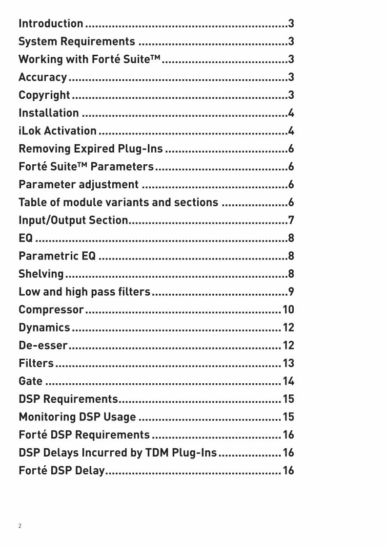
Introduction .............................................................3
System Requirements .............................................3
Working with Forté Suite™ ......................................3
Accuracy ..................................................................3
Copyright .................................................................3
Installation ..............................................................4
iLok Activation .........................................................4
Removing Expired Plug-Ins .....................................6
Forté Suite™ Parameters ........................................6
Parameter adjustment ............................................6
Table of module variants and sections ....................6
Input/Output Section................................................7
EQ ............................................................................8
Parametric EQ .........................................................8
Shelving ...................................................................8
Low and high pass filters .........................................9
Compressor ...........................................................10
Dynamics ...............................................................12
De-esser ................................................................12
Filters ....................................................................13
Gate .......................................................................14
DSP Requirements .................................................15
Monitoring DSP Usage ...........................................15
Forté DSP Requirements .......................................16
DSP Delays Incurred by TDM Plug-Ins ...................16
Forté DSP Delay .....................................................16

3
IntroductionCongratulations on your purchase of the Forté Suite™ plug-in for Pro Tools|HD, HD Accel or LE systems, brought to you by the Focusrite team.
The Forté Suite™ is a high-quality EQ and dynamics plug-in that provides critical control over your audio signals. The Forté Suite™ is a real-time TDM and RTAS plug- in with the look and sound of Focusrite’s original ISA 110 and ISA 130 modules. The Forté Suite™ provides support for 192 kHz, 176.4 kHz, 96 kHz, 88.2 kHz, 48 kHz, and 44.1 kHz sessions.
The Forté Suite™ provides support for multi-mono and stereo formats. In addition, the ISA 130 compressor is available for all Pro Tools-supported multichannel audio formats. Your Forté Suite™ plug-in package contains the following:
− Installation CD-ROM − The Forté Suite™ Plug-In Guide (electronic PDF guide) − Activation code (located on the sticker on the CD case)
System Requirements To use the Forté Suite™, you need:
A Digidesign-qualified Pro Tools|HD, HD Accel or LE system
– or –
A Digidesign-qualified Pro Tools|HD, HD Accel or LE system and a third-party software application that supports the Digidesign TDM, RTAS or Audiosuite plug-in standard
Pro Tools Software Version must be 7.0 or above
For the latest compatibility information, contact your local Digidesign dealer or visit our website (www.digidesign.com/compato).
Working with Forté Suite™ Refer to the Pro Tools Reference Guide, the DigiRack Plug-Ins Guide, or the electronic PDF copy of the Digidesign Plug-Ins Guide for information on working with plug-ins, including:
− Plug-Ins as Inserts − The Plug-In Window − Editing Plug-In Parameters − Automating Plug-Ins − Using the Librarian
Copyright © 2008 Focusrite Audio Engineering Ltd. All rights reserved. No part of this manual may be reproduced, photocopied, or be transmitted / passed to a third party by any means or in any form without the express prior consent of Focusrite Audio Engineering Ltd. DIGIDESIGN, AVID and PRO TOOLS are trademarks or registered trademarks of Digidesign and/or Avid Technology, Inc. All other trademarks are the property of their respective owners. All features and specifications subject to change without notice.

4
Installation To install the Forté Suite™:
1. Insert the Forté Suite CD-ROM into your disk drive. 2. Double click on the Forté Suite installer icon to begin installation. 3. Follow on-screen instructions to complete installation.
The Plug-in fi les will be installed in the following locations:
TDM Plug-in fi les (The Forté Suite.dpm): Mac: Macintosh HD – Library – Application Support – Digidesign – Plug-Ins PC: C:\Program Files \Common Files\Digidesign\DAE\Plug-ins
iLok Activation Forté Suite uses PACE iLok. Before you can use Forté Suite you must register and activate the plug-ins to your iLok.
1. Connect your iLok and run Pro Tools HD. You will be presented with a pop-up window asking you to register.
Make sure you have the activation code to hand. You will fi nd it on a sticker on the back of the Forté Suite installer CD case. It should be in the form 0000-0000-0000-0000
5
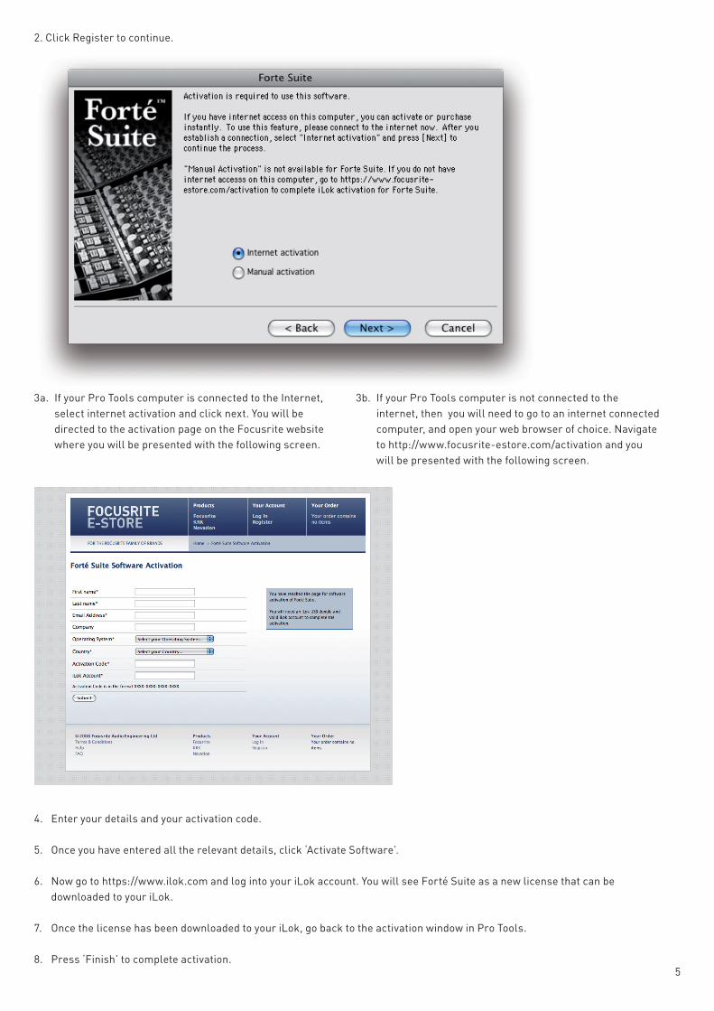
2. Click Register to continue.
4. Enter your details and your activation code.
5. Once you have entered all the relevant details, click ‘Activate Software’.
6. Now go to https://www.ilok.com and log into your iLok account. You will see Forté Suite as a new license that can be downloaded to your iLok.
7. Once the license has been downloaded to your iLok, go back to the activation window in Pro Tools.
8. Press ‘Finish’ to complete activation.
3a. If your Pro Tools computer is connected to the Internet, select internet activation and click next. You will be directed to the activation page on the Focusrite website where you will be presented with the following screen.
3b. If your Pro Tools computer is not connected to the internet, then you will need to go to an internet connected computer, and open your web browser of choice. Navigate to http://www.focusrite-estore.com/activation and you will be presented with the following screen.

6
Forté Suite™ Parameters The Forté Suite™ features the ISA 110 (EQ) and ISA 130 (dynamics) in various arrangements, and boasts an individual compressor module capable of any surround configuration up to 7.1 surround, for quality analogue processing in the digital domain. An extremely high level of design sensitivity means that all the dynamic and real time sonic characteristics of the original ISA channel strips are accurately replicated in the Forté Suite™ plug-in.
Parameter adjustment
There are a variety of options available when modifying parameters within the Forté Suite™:
Dial Rotation
Clicking on the dial (and holding) will allow an adjustment to be made. Subsequent movement on the screen will modify the value; upwards movement increases and downwards movement decreases the value. This value will be displayed in red at the base of the dial as an adjustment is made. NOTE - Holding ‘Alt’ and clicking on a dial will set it to a 0 (default) value.
Numeric typing
As the mouse cursor moves over a dial, its value is displayed in a text box underneath. Clicking on this box will enable an exact value to be entered using the keyboard.
Graphical control
The various graphical displays show the action of the EQ and dynamics, and also allow control of some of the parameters. Clicking on the crosses (and holding) will enable a value to be modified. The corresponding value(s) will appear in red at the base of the relevant dial(s) when an adjustment is made.
Table of module variants and sections
Module variants I/O EQ COMP DYN (De-esser/Gate) ISA 110 • • ISA 130 • • •ISA 110:130 • • • •ISA 130:110 • • • •ISA 130c • •

7
Input/Output Section
Every module variant in the Forté range features an input/output section, as shown above. All 130c multichannel variants contain extra metering to account for the additional channels. The ISA 130c multichannel variants have bar graphs for all channels but only one Input/Output level control, which adjusts all channels equally.
Input and Output dials
The two dials to the left of the bar graph meters allow the user to control the level of gain at the input and output of the module. The accessible gain range is –18dB to +18dB for both dials, with 0dB selected when the dial points vertically upwards (in the centre).
Meters
The vertical bar graph meters indicate the level being fed to the input and output of the module, and the action of the compressor and/or gate when present. They display a range from –40dBFS up to 0dBFS for I/O, and up to 20dB for comp/gate. For surround variants with five channels or more, a in/out switch alternates between showing input and output levels.
8
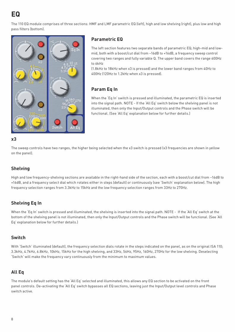
EQ The 110 EQ module comprises of three sections: HMF and LMF parametric EQ (left), high and low shelving (right), plus low and high pass filters (bottom).
Parametric EQ
The left section features two separate bands of parametric EQ; high-mid and low-mid, both with a boost/cut dial from –16dB to +16dB, a frequency sweep control covering two ranges and fully variable Q. The upper band covers the range 600Hz to 6kHz (1.8kHz to 18kHz when x3 is pressed) and the lower band ranges from 40Hz to 400Hz (120Hz to 1.2kHz when x3 is pressed).
Param Eq In
When the ‘Eq In’ switch is pressed and illuminated, the parametric EQ is inserted into the signal path. NOTE - If the ‘All Eq’ switch below the shelving panel is not illuminated, then only the Input/Output controls and the Phase switch will be functional. (See ‘All Eq’ explanation below for further details.)
x3
The sweep controls have two ranges, the higher being selected when the x3 switch is pressed (x3 frequencies are shown in yellow on the panel).
Shelving
High and low frequency-shelving sections are available in the right-hand side of the section, each with a boost/cut dial from –16dB to +16dB, and a frequency select dial which rotates either in steps (default) or continuously (see ‘Switch’ explanation below). The high frequency selection ranges from 3.3kHz to 15kHz and the low frequency selection ranges from 33Hz to 270Hz.
Shelving Eq In
When the ‘Eq In’ switch is pressed and illuminated, the shelving is inserted into the signal path. NOTE - If the ‘All Eq’ switch at the bottom of the shelving panel is not illuminated, then only the Input/Output controls and the Phase switch will be functional. (See ‘All Eq’ explanation below for further details.)
Switch
With ‘Switch’ illuminated (default), the frequency selection dials rotate in the steps indicated on the panel, as on the original ISA 110; 3.3kHz, 4.7kHz, 6.8kHz, 10kHz, 15kHz for the high shelving, and 33Hz, 56Hz, 95Hz, 160Hz, 270Hz for the low shelving. Deselecting ‘Switch’ will make the frequency vary continuously from the minimum to maximum values.
All Eq
The module’s default setting has the ‘All Eq’ selected and illuminated, this allows any EQ section to be activated on the front panel controls. De-activating the ‘All Eq’ switch bypasses all EQ sections, leaving just the Input/Output level controls and Phase switch active.

9
Low and high pass filters
Two dials provide full control of either low pass (upper dial) and high pass (lower dial) filters. Rotating the dials past the ‘off’ position will make the filter active, and allow a continuous or stepped sweep between the frequencies indicated. When ‘switch’ is illuminated, the dial will rotate in steps between the marked frequencies.
Switch
With ‘Switch’ illuminated (default), the frequency selection dials rotate in the steps indicated on the panel, as on the original ISA 110; 16kHz, 12kHz, 8.2kHz, 5.6kHz, 3.9kHz for the low pass filter, and 36Hz, 60Hz, 105Hz, 185Hz, 330Hz for the high pass filter. Deselecting ‘Switch’ will make the frequency vary continuously from the minimum to maximum values.
Phase
Pressing the ‘Phase’ switch inverts the phase of the signal. This function is still active when ‘All Eq’ is deselected.
Overload
The Overload LED indicates when the signal is reaching maximum level, 0dBFS.
Graphical display and control
A graph displays the EQ curve and allows operation of gain and frequency controls for the parametric bands, shelving and filters. Clicking and dragging on one of the yellow crosses changes the parametric band values, whilst the green crosses modify shelving parameters. When the filters are inserted, they appear in red and can be adjusted in the same way. Holding down the Apple key when using a Mac (or the control key using a PC) and clicking on the parametric band will allow modifications to be made to the Q value; a left to right motion scrolling from wide to narrow band. Exact values are displayed in red at the base of the relevant dial when the curve is adjusted.
10
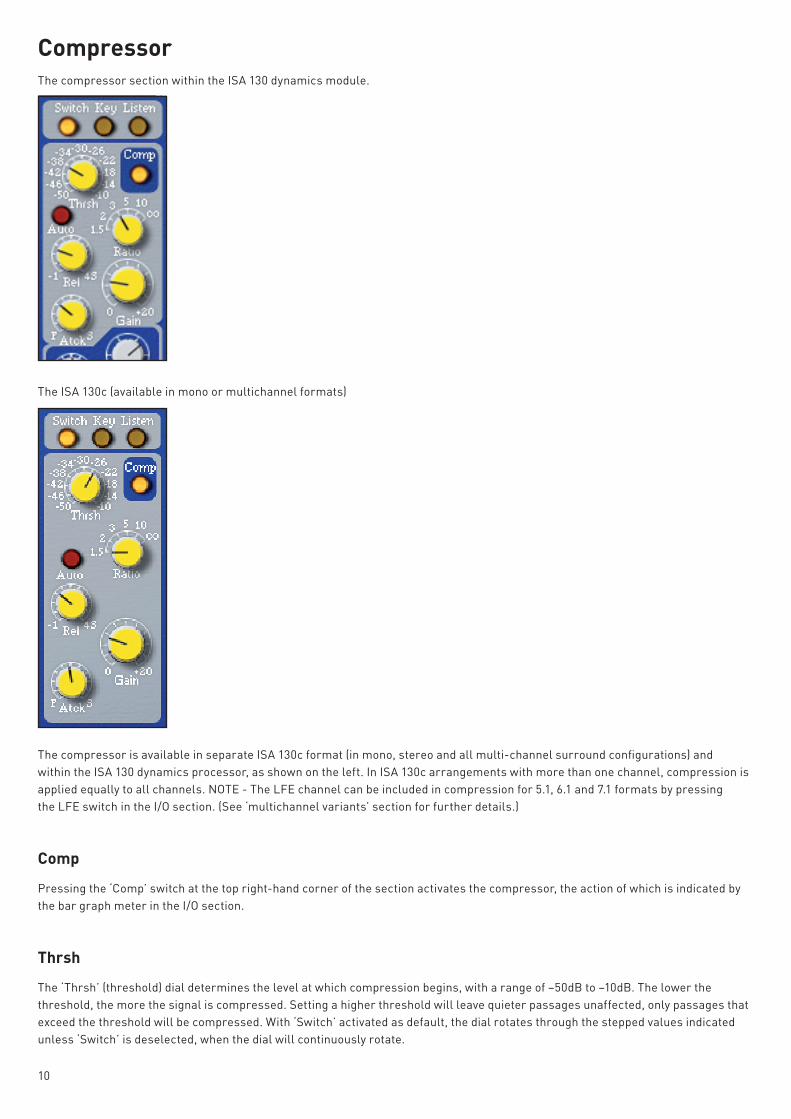
Compressor The compressor section within the ISA 130 dynamics module.
The ISA 130c (available in mono or multichannel formats)
The compressor is available in separate ISA 130c format (in mono, stereo and all multi-channel surround confi gurations) and within the ISA 130 dynamics processor, as shown on the left. In ISA 130c arrangements with more than one channel, compression is applied equally to all channels. NOTE - The LFE channel can be included in compression for 5.1, 6.1 and 7.1 formats by pressing the LFE switch in the I/O section. (See ‘multichannel variants’ section for further details.)
Comp
Pressing the ‘Comp’ switch at the top right-hand corner of the section activates the compressor, the action of which is indicated by the bar graph meter in the I/O section.
Thrsh
The ‘Thrsh’ (threshold) dial determines the level at which compression begins, with a range of –50dB to –10dB. The lower the threshold, the more the signal is compressed. Setting a higher threshold will leave quieter passages unaffected, only passages that exceed the threshold will be compressed. With ‘Switch’ activated as default, the dial rotates through the stepped values indicated unless ‘Switch’ is deselected, when the dial will continuously rotate.

11
Ratio
The ‘Ratio’ dial determines the rate at which compression is applied to a signal with increasing input, and is the ratio of change in input level compared to change in output level. The control gives a range of 1.5 to ∞. With ‘Switch’ activated as default, the dial rotates through the stepped values indicated unless ‘Switch’ is deselected, when the dial will continuously rotate.
Rel
‘Rel’ (release) determines how quickly compression is removed once the level of the source signal has fallen below the threshold. The release time begins at 0.1 seconds (fully anticlockwise), which may be appropriate for rapidly varying signals to avoid compressing the beats that follow, but can result in excessive distortion on more sustained material. Clockwise rotation continuously increases the release time, giving a smoother effect, but which at the same time may result in transients causing audible “pumping”. The maximum release time is 4 seconds.
Atck
‘Atck’ (attack) determines how quickly compression is applied once the level of the source signal has risen above the threshold. The attack time is fastest when fully anticlockwise, making the compressor react to the peak levels of the signal. This is sometimes desirable but can cause unwanted “pumping” of steadier low level components of the signal, due to short transients. Rotating the dial clockwise will increase the attack time, causing the compressor to ignore short transients and respond more to the average loudness of the signal.
Gain
After the overall level has been reduced by compression, the ‘Gain’ dial allows you to increase the output level. 20dB of makeup gain is available.
Auto
When the auto button is pressed, the release curve response is determined by the musical material and the auto release calculation. The release rate varies to suit the dynamics of the signal. This is especially effective on complex programme material, and enables the use of fast attack times without incurring any “pumping” type artefacts. When auto release is pressed in the release knob can still be rotated however the position and release value shown on the release knob has no effect over the release time.
Switch
With ‘Switch’ illuminated (default), the threshold and ratio selection dials rotate in the steps indicated on the panel, as on the original ISA 130. Deselecting ‘Switch’ will make the values vary continuously from the minimum to maximum values.
Key
Pressing the ‘Key’ switch sends the signal routed to the key input to the sidechain of the compressor. Either an interface channel or bus can be assigned by clicking on the Key input block, located on the generic plug-in border. This allows one or more tracks to drive the compressor, to help select the most appropriate form of compression. When compressing a dance track for example, all tracks except for the bass could be sent to the Key input to help retain more natural dynamics in the bass. If no specific key input is selected but the switch is activated, then the regular input to the compressor is used.
Listen
The ‘Listen’ switch enables the compressor’s sidechain to be audibly monitored, ensuring accurate frequency adjustment during setup. Filters can be sent to the sidechain using the switches below the de-esser panel. (See Filters explanation in the Dynamics section below.)
12
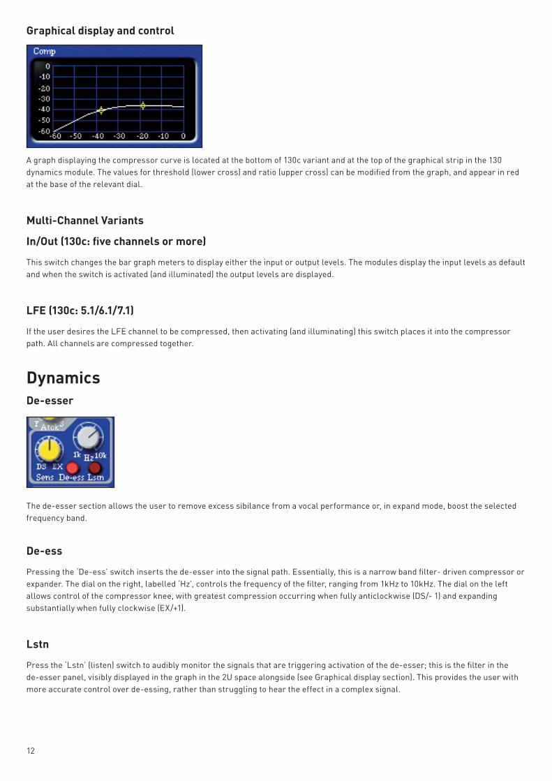
Graphical display and control
A graph displaying the compressor curve is located at the bottom of 130c variant and at the top of the graphical strip in the 130 dynamics module. The values for threshold (lower cross) and ratio (upper cross) can be modified from the graph, and appear in red at the base of the relevant dial.
Multi-Channel Variants
In/Out (130c: five channels or more)
This switch changes the bar graph meters to display either the input or output levels. The modules display the input levels as default and when the switch is activated (and illuminated) the output levels are displayed.
LFE (130c: 5.1/6.1/7.1)
If the user desires the LFE channel to be compressed, then activating (and illuminating) this switch places it into the compressor path. All channels are compressed together.
Dynamics De-esser
The de-esser section allows the user to remove excess sibilance from a vocal performance or, in expand mode, boost the selected frequency band.
De-ess
Pressing the ‘De-ess’ switch inserts the de-esser into the signal path. Essentially, this is a narrow band filter- driven compressor or expander. The dial on the right, labelled ‘Hz’, controls the frequency of the filter, ranging from 1kHz to 10kHz. The dial on the left allows control of the compressor knee, with greatest compression occurring when fully anticlockwise (DS/- 1) and expanding substantially when fully clockwise (EX/+1).
Lstn
Press the ‘Lstn’ (listen) switch to audibly monitor the signals that are triggering activation of the de-esser; this is the filter in the de-esser panel, visibly displayed in the graph in the 2U space alongside (see Graphical display section). This provides the user with more accurate control over de-essing, rather than struggling to hear the effect in a complex signal.

13
Graphical display
The de-esser graph, located below the compressor display, shows the de-esser’s compressor knee (above) as default. ‘Clicking’ on the graph with the mouse will make it display the frequency response of the sidechain’s band pass filter (below). ‘Clicking’ again changes back, and so forth.
Filters
The three switches below the de-esser section select the position of the filters, high and low pass (outer left and right switches respectively) and parametric mid-band (middle switch), in the signal chain. Pressing once illuminates the small yellow LED above the switch, indicating that the filter is sent to the sidechain of the compressor. Pressing again illuminates the small green LED below the switch, indicating that the filter is sent to the sidechain of the gate. Pressing a third time illuminates the actual switch (red), indicating that the filter is in the signal path. To de-activate the filter, simply press the switch a fourth time. As with the original unit, all sidechain filtering occurs after the External Key input.
High and low pass filters
The two dials on the left control the frequency of the low pass (upper dial) and high pass (lower dial) filters. The low pass filter ranges from 1kHz to 20kHz, and the high pass filter ranges from 20Hz to 400Hz.
Parametric mid filter
The two dials on the right control the gain (upper dial) and frequency (lower dial) of the parametric mid filter. These values range from –16dB to +16dB and 60Hz to 600Hz (or 600Hz to 6kHz with ‘x10’ pressed), respectively.
x10
Pressing the ‘x10’ switch multiplies the frequency value on the dial by 10, making the frequency range from 600Hz to 6kHz.
14
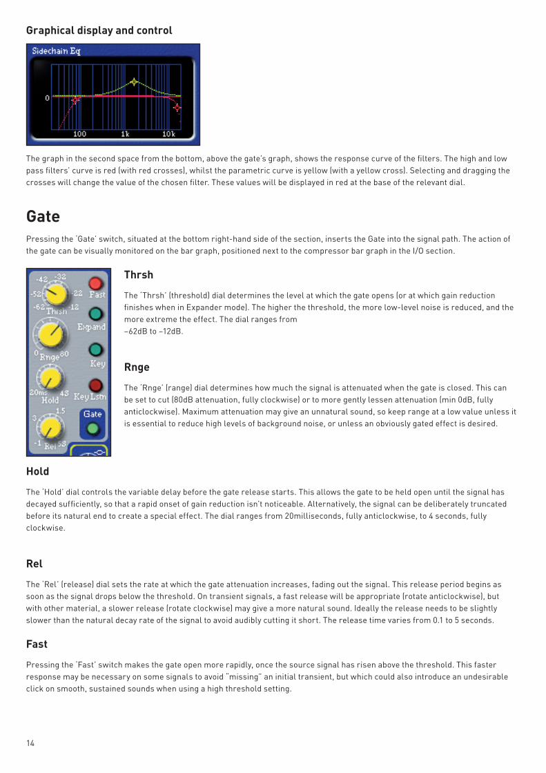
Graphical display and control
The graph in the second space from the bottom, above the gate’s graph, shows the response curve of the filters. The high and low pass filters’ curve is red (with red crosses), whilst the parametric curve is yellow (with a yellow cross). Selecting and dragging the crosses will change the value of the chosen filter. These values will be displayed in red at the base of the relevant dial.
Gate Pressing the ‘Gate’ switch, situated at the bottom right-hand side of the section, inserts the Gate into the signal path. The action of the gate can be visually monitored on the bar graph, positioned next to the compressor bar graph in the I/O section.
Thrsh
The ‘Thrsh’ (threshold) dial determines the level at which the gate opens (or at which gain reduction finishes when in Expander mode). The higher the threshold, the more low-level noise is reduced, and the more extreme the effect. The dial ranges from –62dB to –12dB.
Rnge
The ‘Rnge’ (range) dial determines how much the signal is attenuated when the gate is closed. This can be set to cut (80dB attenuation, fully clockwise) or to more gently lessen attenuation (min 0dB, fully anticlockwise). Maximum attenuation may give an unnatural sound, so keep range at a low value unless it is essential to reduce high levels of background noise, or unless an obviously gated effect is desired.
Hold
The ‘Hold’ dial controls the variable delay before the gate release starts. This allows the gate to be held open until the signal has decayed sufficiently, so that a rapid onset of gain reduction isn’t noticeable. Alternatively, the signal can be deliberately truncated before its natural end to create a special effect. The dial ranges from 20milliseconds, fully anticlockwise, to 4 seconds, fully clockwise.
Rel
The ‘Rel’ (release) dial sets the rate at which the gate attenuation increases, fading out the signal. This release period begins as soon as the signal drops below the threshold. On transient signals, a fast release will be appropriate (rotate anticlockwise), but with other material, a slower release (rotate clockwise) may give a more natural sound. Ideally the release needs to be slightly slower than the natural decay rate of the signal to avoid audibly cutting it short. The release time varies from 0.1 to 5 seconds.
Fast
Pressing the ‘Fast’ switch makes the gate open more rapidly, once the source signal has risen above the threshold. This faster response may be necessary on some signals to avoid “missing” an initial transient, but which could also introduce an undesirable click on smooth, sustained sounds when using a high threshold setting.
15
Expand
Pressing ‘Expand’ causes the gate to function as an expander, which has a similar effect to gating but, instead of cutting off any signal below the threshold, it proportionally decreases it.
Key
Pressing the ‘Key’ switch sends the signal routed to the key input to the sidechain of the gate. Either an interface channel or bus can be assigned by clicking on the Key input block, located on the generic plug-in border.
Key Lstn
The ‘Key Lstn’ switch enables the Key input to be audibly monitored.
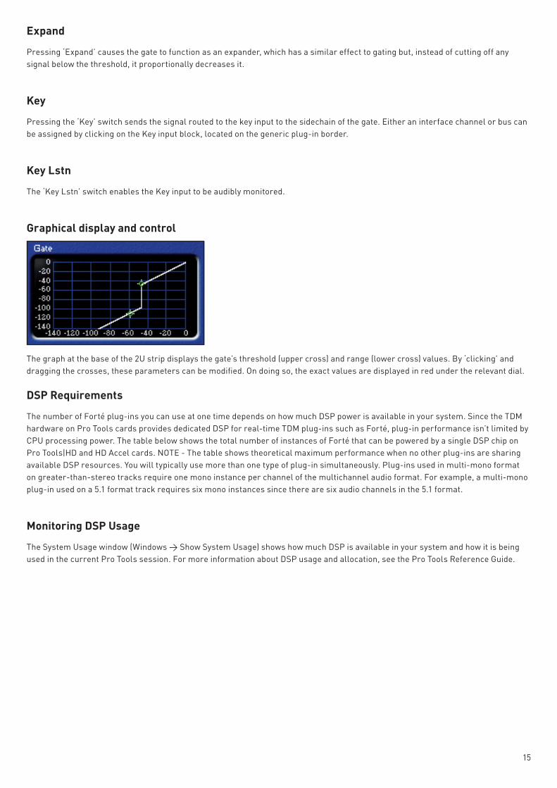
Graphical display and control
The graph at the base of the 2U strip displays the gate’s threshold (upper cross) and range (lower cross) values. By ‘clicking’ and dragging the crosses, these parameters can be modified. On doing so, the exact values are displayed in red under the relevant dial.
DSP Requirements
The number of Forté plug-ins you can use at one time depends on how much DSP power is available in your system. Since the TDM hardware on Pro Tools cards provides dedicated DSP for real-time TDM plug-ins such as Forté, plug-in performance isn’t limited by CPU processing power. The table below shows the total number of instances of Forté that can be powered by a single DSP chip on Pro Tools|HD and HD Accel cards. NOTE - The table shows theoretical maximum performance when no other plug-ins are sharing available DSP resources. You will typically use more than one type of plug-in simultaneously. Plug-ins used in multi-mono format on greater-than-stereo tracks require one mono instance per channel of the multichannel audio format. For example, a multi-mono plug-in used on a 5.1 format track requires six mono instances since there are six audio channels in the 5.1 format.
Monitoring DSP Usage
The System Usage window (Windows > Show System Usage) shows how much DSP is available in your system and how it is being used in the current Pro Tools session. For more information about DSP usage and allocation, see the Pro Tools Reference Guide.

16
Forté DSP Requirements
Maximum instances of Forté plug-in per DSP chip for an HD and HD Accel card at different sample rates
HD HD Accel Plug-in 44.1/48kHz 88.2/96kHz 176.4/192kHz 44.1/48kHz 88.2/96kHz 176.4/192kHz 110 10 4 2 24 11 5 130 4 1 0 9 4 2 110:130 3 1 0 6 3 1 130:110 3 1 0 6 3 1 130c 15 7 2 35 16 7 130c-stereo 12 6 2 29 14 6 130c-LCR 10 5 2 24 11 5 130c-Quad 9 4 1 21 10 4 130c-LCRS 9 4 1 21 10 4 130c-5.0 8 3 1 19 9 4 130c-5.1 7 3 1 17 8 3 130c-6.0 7 3 1 17 8 3 130c-6.1 6 3 1 15 7 3 130c-7.0 6 3 1 15 7 3 130c-7.1 6 2 1 14 6 2
DSP Delays Incurred by TDM Plug-Ins
Virtually all TDM plug-ins incur some amount of signal delay. If you are working with mono tracks, or are processing all channels with the same plug-in, the signal delays are not long enough to be significant and should not be a concern. This signal delay is significant only if you use a plug-in on one channel of a stereo or multichannel signal but not the others, since this can cause the channels to be slightly out of phase. The delay incurred by the Forté plug-in is 4 samples (at all sample rates).
Channel Delay Indicator
The Channel Delay Indicator in the Mix window displays the total delay, in samples, incurred on the track from the use of any TDM plug-in on that channel. To see the amount of time delay on a track that uses plug-in inserts.
- In the Mix window, Control-click (Windows) or Command-click (Macintosh) the track’s Volume Indicator to toggle between Volume (“vol”), Peak (“pk”) and Channel Delay (“dly”) indications.
Compensating For Delays
Pro Tools HD users should not need to manually compensate for delay as this is done automatically. Pro Tools LE users must manually compensate for delays incurred. To compensate for plug-in delay, use the TimeAdjuster plug-in included with Pro Tools to offset other tracks, as appropriate. See the DigiRack Plug-Ins Guide or Pro Tools Reference Guide for more information on TimeAdjuster. For a comprehensive guide to calculating DSP-induced delays, see the Pro Tools Reference Guide.
Troubleshooting
For all troubleshooting, please refer to the online Answerbase at www.focusrite.com/answerbase