Embed Size (px)
Citation preview
Svensk Kärnbränslehantering ABSwedish Nuclear Fueland Waste Management CoBox 5864SE-102 40 Stockholm Sweden Tel 08-459 84 00 +46 8 459 84 00Fax 08-661 57 19 +46 8 661 57 19
P-05-168
Forsmark site investigation
Vertical seismic profiling from the boreholes KFM01A and KFM02A
Calin Cosma, Nicoleta Enescu, Lucian Balu
Vibrometric
June 2005
ISSN 1651-4416
SKB P-05-168
Keywords: VSP, Vertical seismic profiling, Forsmark, KFM01A, KFM02A, AP PF 400-04-60.
This report concerns a study which was conducted for SKB. The conclusions and viewpoints presented in the report are those of the authors and do not necessarily coincide with those of the client.
A pdf version of this document can be downloaded from www.skb.se
Forsmark site investigation
Vertical seismic profiling from the boreholes KFM01A and KFM02A
Calin Cosma, Nicoleta Enescu, Lucian Balu
Vibrometric
June 2005
3
Abstract
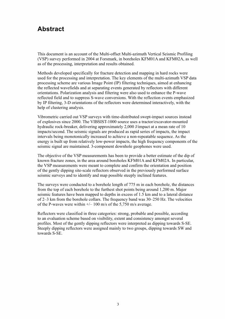
This document is an account of the Multi-offset Multi-azimuth Vertical Seismic Profiling (VSP) survey performed in 2004 at Forsmark, in boreholes KFM01A and KFM02A, as well as of the processing, interpretation and results obtained.
Methods developed specifically for fracture detection and mapping in hard rocks were used for the processing and interpretation. The key elements of the multi-azimuth VSP data processing scheme are various Image Point (IP) filtering techniques, aimed at enhancing the reflected wavefields and at separating events generated by reflectors with different orientations. Polarization analysis and filtering were also used to enhance the P-wave reflected field and to suppress S-wave conversions. With the reflection events emphasized by IP filtering, 3-D orientations of the reflectors were determined interactively, with the help of clustering analysis.
Vibrometric carried out VSP surveys with time-distributed swept-impact sources instead of explosives since 2000. The VIBSIST-1000 source uses a tractor/excavator-mounted hydraulic rock-breaker, delivering approximately 2,000 J/impact at a mean rate of 10 impacts/second. The seismic signals are produced as rapid series of impacts, the impact intervals being monotonically increased to achieve a non-repeatable sequence. As the energy is built up from relatively low-power impacts, the high frequency components of the seismic signal are maintained. 3-component downhole geophones were used.
The objective of the VSP measurements has been to provide a better estimate of the dip of known fracture zones, in the area around boreholes KFM01A and KFM02A. In particular, the VSP measurements were meant to complete and confirm the orientation and position of the gently dipping site-scale reflectors observed in the previously performed surface seismic surveys and to identify and map possible steeply inclined features.
The surveys were conducted to a borehole length of 775 m in each borehole, the distances from the top of each borehole to the furthest shot points being around 1,200 m. Major seismic features have been mapped to depths in excess of 1.5 km and to a lateral distance of 2–3 km from the borehole collars. The frequency band was 30–250 Hz. The velocities of the P-waves were within +/– 100 m/s of the 5,750 m/s average.
Reflectors were classified in three categories: strong, probable and possible, according to an evaluation scheme based on visibility, extent and consistency amongst several profiles. Most of the gently dipping reflectors were interpreted as dipping towards S-SE. Steeply dipping reflectors were assigned mainly to two groups, dipping towards SW and towards S-SE.
4
Sammanfattning
Denna rapport beskriver vertikal seismisk profilering (VSP) utförd i Forsmark 2004 i borrhålen KFM01A och KFM02A. Rapporten beskriver även processering och tolkning av data samt diskuterar resultaten.
I processeringen och tolkningen användes metoder specifikt utvecklade för att detektera och orientera sprickzoner i kristallint berg. De viktigaste stegen i sk multi-azimuth VSP är en spegelpunkt (”Image Point”, IP) filtreringsteknik som syftar till att förstärka reflekterade vågfronter och separera signalen från reflektorer med olika orienteringar. För att förstärka de reflekterade P-vågarna och undertrycka S-vågs konversion användes polarisationsanalys och filtrering. Reflektorernas orientering i rummet bestämdes därefter interaktivt med hjälp av såkallad ”clustering analysis”.
Vibrometric har utförd VSP undersökningar med hydraulisk hammare sedan år 2000. Denna VIBSIST teknik består av en traktorgrävare med en hydraulisk hammare som presterar ca 2 000 J per slag med i genomsnitt ca 10 slag per sekund. Den seismiska signalen skapas genom en snabb serie av slag, där slagintervallet ändras monotont för att åstadkomma en lämplig sekvens. Eftersom den seismiska signalen byggs upp av slag med förhållandevis låg energi, bibehålls de höga frekvenserna. I borrhålen användes 3-komponent geofoner.
Syftet med VSP undersökningarna var att bestämma orienteringen av sprickzoner i området runt kärnborrhålen KFM01A och KFM02A. Speciellt viktigt var att säkerställa och bekräfta orienteringen och läget av de svagt stupande reflektorerna som observerades i tidigare utförda markbaserade reflektionsseismiska undersökningar, samt möjligheten att identifiera eventuella brant stupande reflektorer.
Undersökningarna utfördes ned till en borrhålslängd på 775 m i varje borrhål. Det största avståndet från borrhålens topp till skottpunkterna var 1 200 m. Signifikanta seismiska reflektorer har observerats ned till djup som överstiger 1 500 m och horisontellt upp till 2–3 km från borrhålen. Frekvensbandet var 30–250 Hz, och de observerade P-vågs-hastigheterna var inom intervallet 5 750 m/s ± 100 m/s.
Reflektorerna klassificerades i tre kategorier: starka, sannolika och möjliga. Denna kategorisering baserar sig på visibilitet, utsträckning och konsistens mellan observationer från flera profiler. De flesta svagt stupande reflektorer tolkades som stupande mot S-SO. De brant stupande reflektorerna förekommer i två huvudgrupper, stupande mot SV respektive mot S-SO.

5
Contents
1 Introduction 7
2 Objective and scope 11
3 Equipment 133.1 The seismic source – VIBSIST-1000 133.2 The seismic receivers – the Vibrometric R8-XYZ-C geophones 153.3 The recording station 16
4 Execution 174.1 General 174.2 Preparations 194.3 Execution of field work 19
5 Processing and interpretation of the VSP data 215.1 VSP data processing 21
5.1.1 Data quality and frequency analysis 215.1.2 Rotation of horizontal components 225.1.3 Velocity determinations 245.1.4 Suppression of direct P-wave and S-waves 245.1.5 Amplitude compensation and equalization 265.1.6 Image point filtering and reflector enhancement in the
image space 26
6 Interpretation of the VSP data measured from boreholes KFM01A and KFM02A 31
6.1 3D interpretation of reflectors from the VSP data acquired in borehole KFM01A 33
6.2 3D interpretation of reflectors from the VSP data acquired in borehole KFM02A 43
6.4 Nonconformities 52
7 Results 537.1 Parameters of reflectors interpreted from KFM01A 547.2 Parameters of reflectors interpreted from KFM02A 577.3 Combination of reflectors from KFM01A and KFM02A 60
References 63
Appendix A 65
Appendix B 71

7
1 Introduction
This document reports the Multi-offset Multi-azimuth Vertical Seismic Profiling (VSP) survey performed in boreholes KFM01A and KFM02A in 2004, as well as the processing, interpretation and results obtained. The work was carried out following the Activity Plan AP PF 400-04-60. The documents describing the activity are listed in Table 1-1.
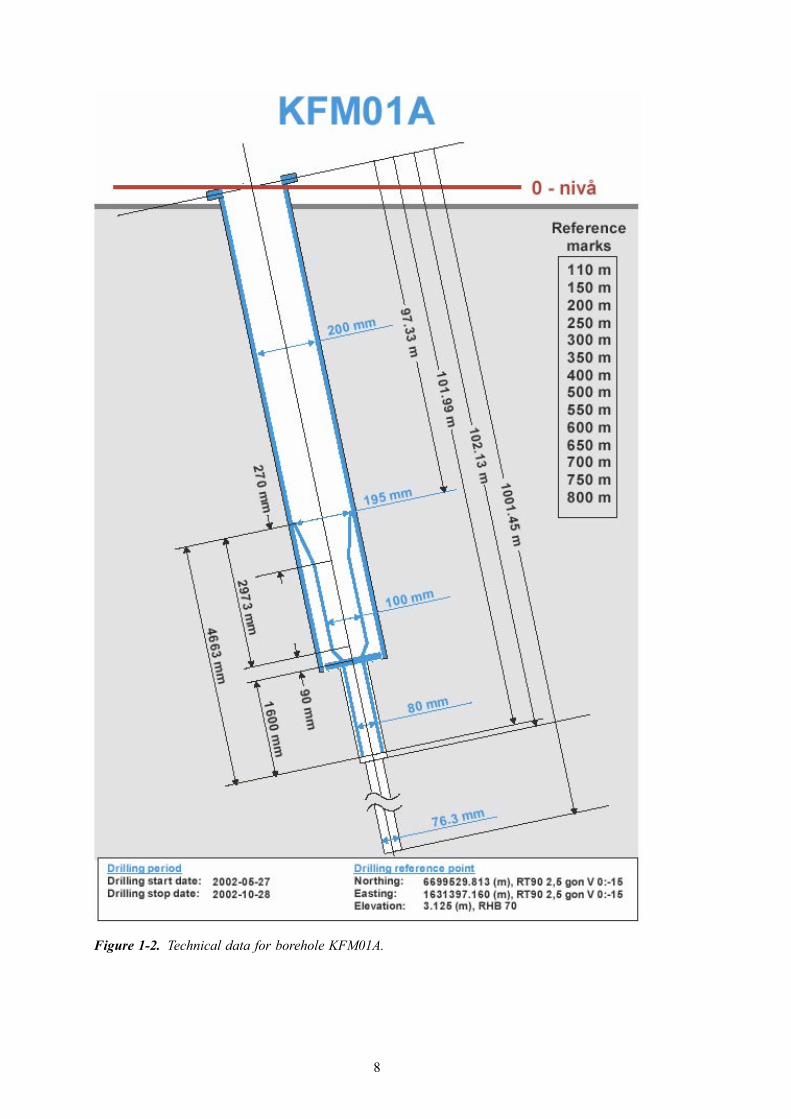
The locations of the boreholes and of the shotpoints are shown on the map in Figure 1-1. Figure 1-2 and Figure 1-3 display construction details of the boreholes.
Table 1-1. Controlling documents for the performance of the activity.
Activity plan Number Version
Vertical Seismic Profiling (VSP) AP PF 400-04-60 1.0
Method descriptions Number Version
Method description for Vertical Seismic Profiling (VSP) SKB MD 243.004 1.0
Figure 1-1. Map of the Forsmark investigation area showing the location of the boreholes KFM01A (DS1) and KFM02A (DS2). The shot points are indicated with black dots.
8
Figure 1-2. Technical data for borehole KFM01A.

9
Figure 1-3. Technical data for borehole KFM02A.

10
Multi-offset VSP has been used, over the past 20 years, for mapping fractures and fracture zones with various hard rock applications, from nuclear waste disposal /Cosma et al. 2001a/, to ore delineation /Keskinen et al. 1999/, to rock engineering /Keskinen et al. 2000/. Fracture zones in hard rock may display a weak seismic contrast and specialist-imaging techniques must often be used to identify them. One method that produced good results in the past is based on computing time-depth functions for all possible reflectors in a given rock volume and investigating the coherency along each such path. Actual reflection events are emphasized in the process even if they do not display a remarkable amplitude standout in the raw profiles /Cosma, 1995, 1990/.
The VSP method provides a favorable geometry for mapping both steeply and gently dipping features /Cosma et al. 2001b/. Receivers located in the bedrock minimize the loss of resolution due to near-surface signal absorption.
Recent surveys /Juhlin et al. 2002, Cosma et al. 2002a/ have been carried out with a time-distributed swept-impact source, the VIBSIST /Enescu and Cosma, 1999; Cosma and Enescu, 2001/, instead of explosives. With this source, the seismic signals are produced as rapid series of impacts, the impact intervals being monotonically increased to achieve a non-repeatable sequence. As the energy is built up from a large number of relatively low-power impacts, the high frequency components of the seismic signal are maintained.
Methods developed over the past 10 years /Cosma et al. 1994a, 1994b; Heikkinen et al. 1994, 1995/ and recently summarized in /Cosma and Enescu, 2002b/ were used for the processing and interpretation, e.g. the interactive determination of the orientation of the fracture zones (reflecting interfaces) using simultaneously several VSP boreholes.
The data processing usually starts with procedures aimed at reducing or eliminating tube-waves and direct P and S onsets. Median and band-pass filters are used for this purpose. Further processing consists mainly of Image Point (IP) filtering techniques, aimed at enhancing the reflected wavefields and at separating events generated by reflectors with different orientations. With the IP transform, introduced by /Cosma, 1990; Cosma and Heikkinen 1996/, stacking is performed along hyperbolic paths corresponding to the time-depth functions of possible reflectors. Due to this ”natural” choice of the stacking paths, the coherency can be used effectively to enhance the weak reflections. When all the profiles have been processed and the reflection events emphasized by IP filtering, 3-D orientations of the reflectors are determined interactively with the help of statistical methods, e.g. clustering analysis.
11
2 Objective and scope
The general goal of the VSP measurements has been to provide a better estimate of the dip of known fracture zones, identified by other methods, in the area around boreholes KFM01A and KFM02A. The expected result is a better understanding of the geometry of the zones.
In particular, the VSP measurements were meant to complete and confirm the orientation and position of the gently dipping site-scale reflectors observed in the previously performed surface seismic surveys and to identify and map possible steeply inclined features.
The surveys were conducted in boreholes KFM01A and KFM02A, to a maximum depth of 775 m in each borehole. As a rule of the thumb, sub-horizontal and gently dipping seismic targets can be mapped to a depth of one and a half times the depth of the boreholes and steeply dipping targets to a lateral distance of the order of the depth of the boreholes. However, this rather conservative estimate can roughly be increased twofold if the same investigation volume can be imaged from several boreholes and the seismic targets are nearly planar and continuous over distances comparable with the borehole depth. Hence, in the case of KFM01A and KFM02A, the imaging of nearly planar and extensive seismic features has been attempted to depths in excess of 1.5 km.
To aid the estimation of the azimuth of the seismic imaging targets, the measuring routine attempts to achieve a consistent directional response of the 3-component receivers by keeping them clamped to the borehole in the same positions while the source moves from one shotpoint to another. However, as two sources were used, the shot points have been assigned to two groups, each group containing at least four shotpoints. The receivers were unclamped and moved only when all shotpoints in both groups had been recorded.

13
3 Equipment
3.1 The seismic source – VIBSIST-1000A time-distributed seismic source, the VIBSIST-1000, was used for the VSP surveys. The VIBSIST-1000 is based on the Swept Impact Seismic Technique (SIST), /Park et al. 1996; Cosma and Enescu, 2001/.
At each shot point, the VIBSIST source was activated for a period of 15–20 seconds during which time the impact frequency has been varied to generate a swept impact sequence. The sweep was repeated five times and, when needed, up to ten times to obtain a high signal-to-noise ratio.
The SIST concept requires a pilot signal to be measured by a sensor placed on the source or in its immediate vicinity, conveyed to the recording station and recorded together with the signals arriving from the receivers. Pilot signal cables were drawn from each shot point to the receiver borehole.
The VIBSIST-1000 source uses a tractor/excavator-mounted hydraulic rock-breaker, powered through a computer controlled flow regulator. The Forsmark VSP survey was performed with two sources, one mounted on a 12 ton Huddig 960 tractor and another on an 18 ton Atlas 1504 excavator. These were equipped with hammers delivering 1,500 and 2,500 J/impact at 400–800 impacts/minute. The computer-controlled flow regulator produced about 100 impacts per sweep.
The source coupling was generally similar from one shotpoint to another being however occasionally influenced by local variations of the ground conditions. A larger number of sweeps (up to 10) was used to compensate for poorer ground conditions. Interpretable data was acquired at each shot location, except shot point no 5 for KFM02A, which initially produced poor results. It was found that underground facilities exist in that region and the shot point was abandoned. To allow the mapping of structures dipping in various directions, the shot points were located at various azimuths around the VSP boreholes (see Figure 1-1, where the shots are marked with black dots and labeled in red).

14
Figure 3-1. The VIBSIST-1000 seismic sources used as a seismic source at Forsmark for the 2004 VSP surveys.
15
3.2 The seismic receivers – the Vibrometric R8-XYZ-C geophones
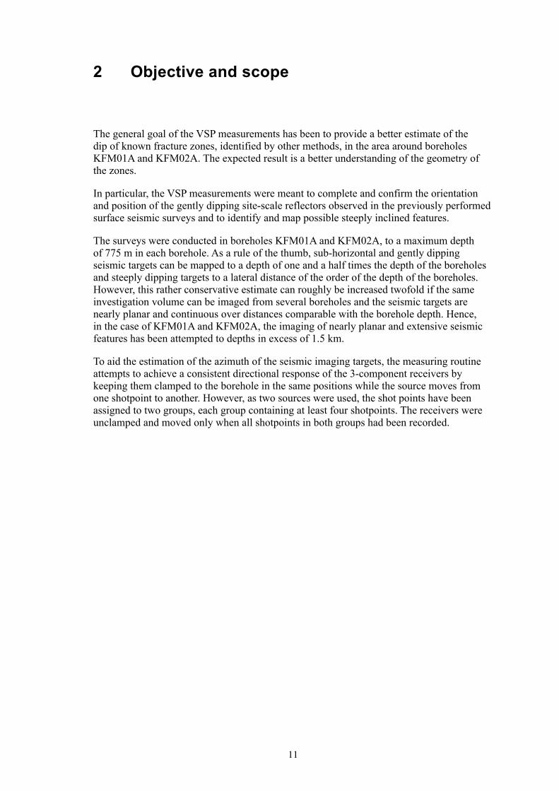
A 3-component geophone chain was used for the VSP measurements. The R8-XYZ-C geophone chain is equipped with 24 28-Hz geophones placed in eight 3-component modules (Figure 3-2). The z-component is directed along the hole and the x- and y-components are perpendicular to the z-component and to each other. The distance between the modules is five metres. The geophone chain contains also a down-hole preamplifier for each channel. The gain of the amplifiers is fixed at 34.2 dB. The frequency range is from 40 to 1,000 Hz. The overall sensitivity of the geophone-amplifier combination is 133 V/cm/sec. The units are equipped with side arms for clamping, activated by DC motors. The clamping control is independent for each unit.
Figure 3-2. Picture of the R8-XYZ-C geophone receiver chain and detail of a 3-component module with clamping arm.
16
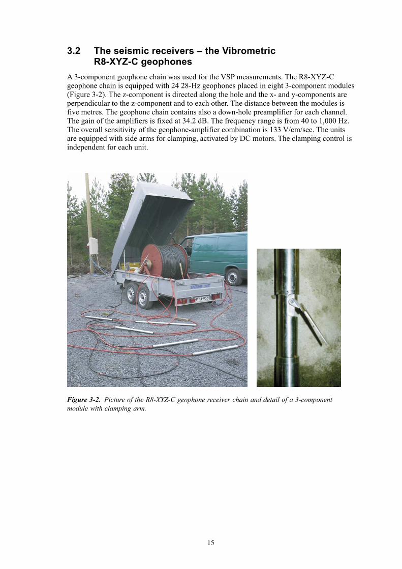
3.3 The recording stationA PC-based acquisition system was used (Figure 3-3), consisting of an ICS 32-channels, 24-bits acquisition board, with LabView based acquisition interface.
The PC-based solution has been chosen instead of a standard 24-bit seismograph because of the unusually long records needed (100,000 samples/channel for a 20 s sweep at 0.2 ms sampling rate), which is unavailable with standard seismographs. The custom-written software allows concurrent signal processing, needed for on-line checking of the signal quality. The decoded seismic record is built by 32-bit stacking of approximately 1,000 individual pulses. The data is recorded on an internal hard disk in the ACH Vibrometric format.
Figure 3-3. The acquisition station used for the surveys at Forsmark.

17
4 Execution
4.1 GeneralThe VSP investigations were carried out during 2004 in boreholes KFM01A and KFM02A. Figure 4-1 shows the layout of the boreholes and of the shot point locations. There are 20 shot point locations that were used around two boreholes. Technical details on these boreholes are given in Figure 1-2 and Figure 1-3.
Figure 4-1. Layout of boreholes and shot points used for the VSP investigations (see also Figure 1-1).
18
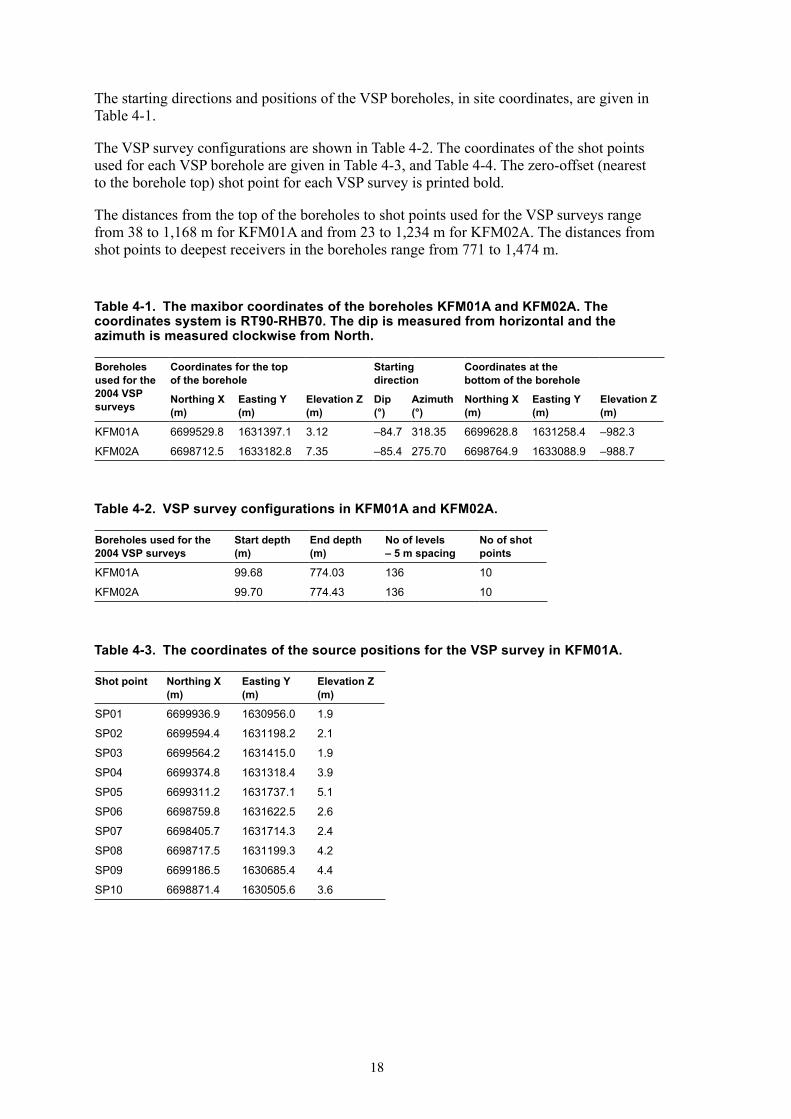
The starting directions and positions of the VSP boreholes, in site coordinates, are given in Table 4-1.
The VSP survey configurations are shown in Table 4-2. The coordinates of the shot points used for each VSP borehole are given in Table 4-3, and Table 4-4. The zero-offset (nearest to the borehole top) shot point for each VSP survey is printed bold.
The distances from the top of the boreholes to shot points used for the VSP surveys range from 38 to 1,168 m for KFM01A and from 23 to 1,234 m for KFM02A. The distances from shot points to deepest receivers in the boreholes range from 771 to 1,474 m.
Table 4-1. The maxibor coordinates of the boreholes KFM01A and KFM02A. The coordinates system is RT90-RHB70. The dip is measured from horizontal and the azimuth is measured clockwise from North.
Boreholes used for the 2004 VSP surveys
Coordinates for the top of the borehole
Starting direction
Coordinates at the bottom of the borehole
Northing X (m)
Easting Y (m)
Elevation Z (m)
Dip (°)
Azimuth (°)
Northing X (m)
Easting Y (m)
Elevation Z (m)
KFM01A 6699529.8 1631397.1 3.12 –84.7 318.35 6699628.8 1631258.4 –982.3
KFM02A 6698712.5 1633182.8 7.35 –85.4 275.70 6698764.9 1633088.9 –988.7
Table 4-2. VSP survey configurations in KFM01A and KFM02A.
Boreholes used for the 2004 VSP surveys
Start depth (m)
End depth (m)
No of levels – 5 m spacing
No of shot points
KFM01A 99.68 774.03 136 10
KFM02A 99.70 774.43 136 10
Table 4-3. The coordinates of the source positions for the VSP survey in KFM01A.
Shot point Northing X (m)
Easting Y (m)
Elevation Z (m)
SP01 6699936.9 1630956.0 1.9
SP02 6699594.4 1631198.2 2.1
SP03 6699564.2 1631415.0 1.9
SP04 6699374.8 1631318.4 3.9
SP05 6699311.2 1631737.1 5.1
SP06 6698759.8 1631622.5 2.6
SP07 6698405.7 1631714.3 2.4
SP08 6698717.5 1631199.3 4.2
SP09 6699186.5 1630685.4 4.4
SP10 6698871.4 1630505.6 3.6

19
4.2 PreparationsThe field campaign started on August 2nd, 2004 and carried on until August 22nd, 2004. An introductory meeting was held during the first day, followed by field reconnaissance and identification of the shot point locations. Trigger cables were spread first on the North side and then on the South side, for all shot points used with borehole KFM02A. Cable continuity was checked for all cables. The acquisition of VSP data proceeded first with only one Vibsist source since the second tractor was not available at the time. Full production with two tractors commenced several days later. Once the acquisition of all VSP profiles was completed for borehole KFM02A, the work proceeded for borehole KFM01A.
4.3 Execution of field workThe required number of sweeps used at each shot point was continuously re-evaluated as the survey progressed. The standard quality control procedure consisted of evaluating the signal-to-noise ratio of the first sweep and based on this observation a choice of 5 or 10 sweeps was determined. The quality control procedure also included the inspection of the last sweep recorded to ensure that the equipment had functioned properly. The number of sweeps was also increased as a function of the shot-receiver distance.
Following each data acquisition day, the raw data files were backed-up and deconvolved from long sweeps to primary (short) raw data files.
Table 4-4. The coordinates of the source positions for the VSP survey in KFM02A.
Shot point Northing X (m)
Easting Y (m)
Elevation Z (m)
SP01 6698694.7 1633167.8 5.3
SP02 6698930.8 1633422.6 1.5
SP03 6699416.9 1633326.4 3.1
SP04 6699683.5 1632940.5 2.5
SP05 6699724.2 1632476.3 2.0
SP06 6698040.6 1632613.9 4.2
SP07 6698112.9 1632967.0 2.2
SP08 6698488.3 1633328.7 4.3
SP09 6698121.7 1633272.2 3.7
SP10 6698000.7 1633543.0 5.3
21
5 Processing and interpretation of the VSP data
5.1 VSP data processingThe processing sequence aims to improve the signal-to-noise ratio, so that the later events, e.g. reflections, become visible. As the reflection coefficients are generally low, the reflectors cannot normally be identified by amplitude standout alone. Phase consistency has also been found to be a sensitive indicator.
The processing sequence consists of:→ Frequency filtering;→ Picking of the first arrival times and velocity analysis;→ Rotation of the horizontal components to radial (R) and transverse (T), where “radial”
stands for the direction perpendicular to the hole and pointing towards the source and “transverse” for the direction perpendicular to the radial and to the hole;
→ Eliminating such wave-fields as the direct P, direct S and tube-waves, so that the reflections become visible. The direct wave fields and other coherent disturbances are removed by slant median filtering and the signal levels are adjusted in such a way that the amplitudes of different traces and different parts of the same trace become comparable;
→ Image Space (IP) processing, which is done to enhance the reflected wave fields and separate reflection events originating at interfaces with different orientations;
→ Image Space non-linear enhancement of reflected energy;
Once all the profiles have been processed and the reflection events emphasized, the positions of the reflectors are determined by interactive interpretation.
All data processing has been realized using Vibrometric proprietary software, which contains several unique routines developed, over the past two decades, specifically for multi-offset VSP imaging in hard rocks.
5.1.1 Data quality and frequency analysis
The data has been inspected for possible malfunctions of the measuring system, unusually high noise levels, possible errors in coordinates, time delays and trace order. At the end of this process all errors, if any, falling in the categories listed above were corrected.
The following operations were completed during this processing stage:• The geometry information was incorporated into the data profiles. • The data was band-pass filtered in the frequency band of the seismic signal. The
frequency band selected for the filter is as wide as possible, the rejected spectral components corresponding to clearly identified sources of noise. The frequency band of the P-waves was estimated to be 30–250 Hz. A zero-phase band-pass filter [30–250] Hz was used to filter all data profiles. The frequency content of the recorded data is illustrated in Figure 5-1, which displays the spectra of the data profiles shown in Figure 5-4 (left) and Figure 5-8 (right).

22
• The signal levels were adjusted so that the average amplitudes of different traces and different parts of the same trace become comparable.
5.1.2 Rotation of horizontal components
The orientation of the horizontal components (X and Y) is not set or determined during the measurements and, due to the free rotation of the down-hole probes while changing position, the horizontal components show a poor trace-to-trace consistency in both amplitude and phase.
The rotation of the horizontal components is done computationally, assuming that the direct P wave is polarized along the source-receiver line. The X-Y trace pair is rotated so that after rotation the X component acquires the most possible of the P-wave energy and becomes the ”Radial” component, while the Y component contains the minimum possible of the P-wave energy becomes the ”Transverse” component. The Z-component remains directed along the borehole and it becomes the ”Axial” component.
The radial, transverse and the axial components from KFM01A shot point SP03 are presented as an example in Figure 5-2, Figure 5-3 and Figure 5-4. KFM01A SP03 is a zero-offset shot point; see Figure 4-1. The direction of propagation from the source to receivers is along the borehole and the transverse component aligning procedure described above, based on the direct P-wave polarization cannot be applied.
As the receivers were not moved between the shots in the same group, the aligning has been done by extrapolating the polarization analysis made on the far-offset shots.
One does notice amplitude predominance of the direct P-wave arrivals in the axial (Z) component, Figure 5-4, while S-waves and PS-conversions predominate in the transverse components R and T. These conversions can provide certain structural information, as detailed in Figure 5-5.
Figure 5-1. Spectra of the axial, Z-component, profile measured from SP03 at KFM01A (left) and from SP02 at KFM02A (right).

23
Figure 5-2. Raw data profile KFM01A, shot point SP03, radial (R) component.
Figure 5-3. Raw data profile KFM01A, shot point SP03, transverse (T) component.
Figure 5-4. Raw data profile KFM01A, shot point SP03, axial (Z) component.

24
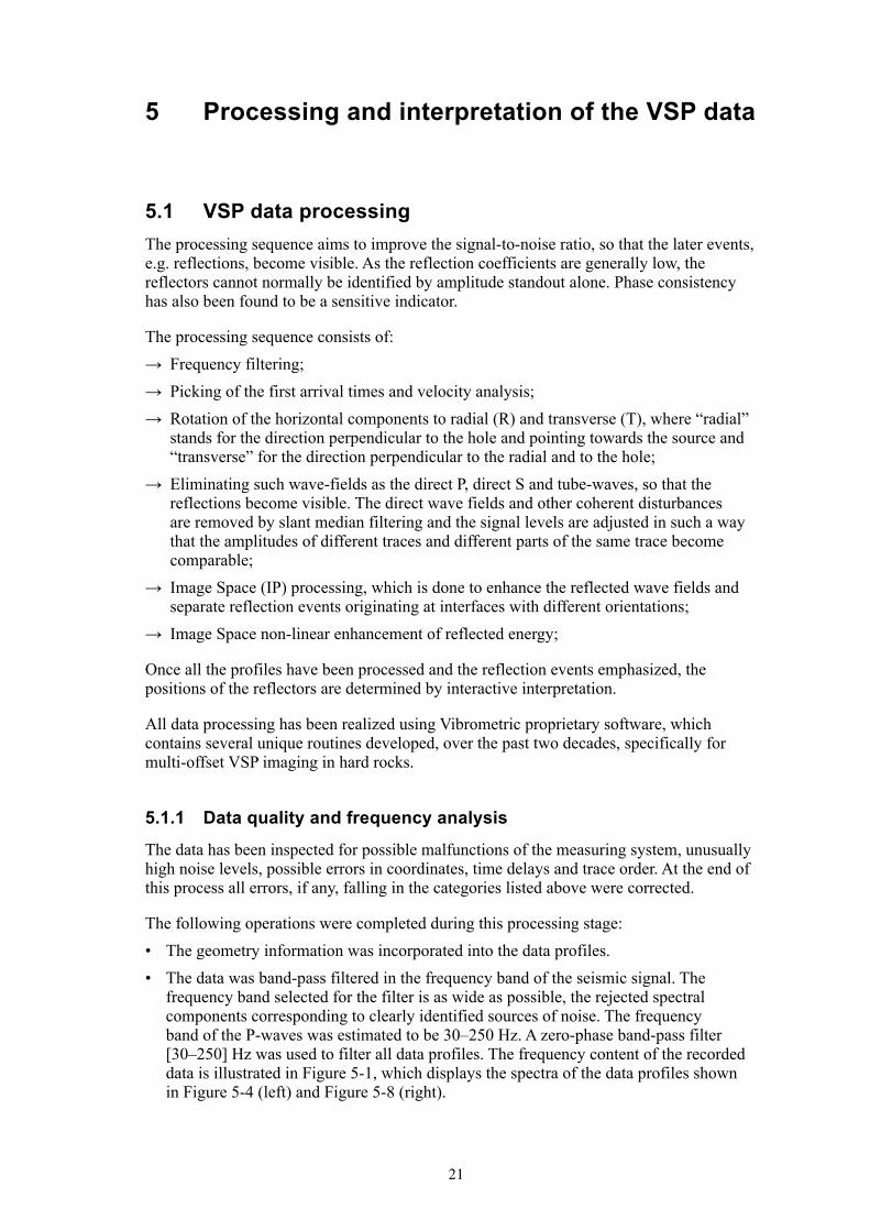
The radial, transverse and axial components from KFM02A shot point SP02 are presented in Figure 5-6, Figure 5-7 and Figure 5-8. SP02 is a relatively near (but not zero) offset shot point. However, there is clearly observable direct P-wave energy in the radial component and corresponding direct S-wave energy in the transverse component, see Figure 5-6 and Figure 5-7, respectively. P-S wave conversions are also visible and can be associated with structure, as explained in Figure 5-9.
5.1.3 Velocity determinations
The velocity fields for all profiles measured in boreholes KFM01A and KFM02A show no abnormal characteristics. The interval velocities (slope of the trajectory length vs. travel time) remain within +/– 100 m/s of the 5,750 m/s average for all shot points.
5.1.4 Suppression of direct P-wave and S-waves
An efficient way to eliminate direct P-wave and/or S-wave arrivals is by means of median filters or adaptive median filters taken along the slopes corresponding to +/– the P-wave and/or S-wave velocity. The trajectory along which median filtering is done is not straight, but follows the true travel time curve. The direct P-wave energy along 5,750 m/s paths was removed from the VSP profiles, followed by the removal of the direct S-wave energy, along 3,450 m/s paths.
Figure 5-5. Raw data profile KFM01A, shot point SP03, transverse (T) component. The event marked with a cyan line corresponds to a P-S conversion (Vp = 5,750 m/s to Vs = 3,450 m/s) generated by a gently dipping interface (Dip = 20°), which intersects the borehole at 220–240 m.
25
Figure 5-6. Raw data profile KFM02A, shot point SP02, radial (R) component.
Figure 5-7. Raw data profile KFM02A, shot point SP02, transverse (T) component.
Figure 5-8. Raw data profile KFM02A, shot point SP02, axial (Z) component.

26
5.1.5 Amplitude compensation and equalization
Amplitude compensation (AGC) is performed to cancel the effects of geometrical spreading and attenuation and to reconstruct the original amplitude variations along the trace. A variable gain operator is run along the records to increase the amplitude of later events assumed to have traveled along longer paths. The amplitude compensation for all three components was done with the same operator, estimated in a 50 ms window, so that the amplitude ratio between the components is conserved after AGC.
The pre-processed profiles from borehole KFM01A, shot point SP03 are presented in Figure 5-10, Figure 5-11 and Figure 5-12. Weak coherent reflection patterns start to be visible after pre-processing.
5.1.6 Image point filtering and reflector enhancement in the image space
One of the properties of the Image Point transform /Cosma, 1995; Cosma and Heikkinen, 1996/ is that, if the velocity field is correctly modeled, the coherent energy adds in phase (along hyperbolic paths), producing well-defined maxima in the IP (Image Point) space. This offers possibilities for advanced intricate processing; including enhanced polarization analysis, azimuth and dip filtering, as well as non-linear coherency-enhancement schemes.
A novelty of the processing of the Forsmark VSP data was that the Image Point processing was applied independently on panels of 27 traces instead of whole panels containing 136 traces. This was done in order to allow potentially discontinuous seismic targets to be shown as such, without forcing continuity by coherency enhancement over the whole depth range of the shot gather profiles.
Figure 5-9. Raw data profile KFM02A, shot point SP02, radial (R) component. The event marked with a cyan line corresponds to a P-S conversion (Vp = 5,750 m/s to Vs = 3,450 m/s) generated by a gently dipping interface (Dip = 20°), which intersects the borehole at 330–340 m. The event marked with a blue line corresponds to a P-S conversion (Vp = 5,750 m/s to Vs = 3,450 m/s) generated by a gently dipping interface (Dip = 20°), which intersects the borehole at 90–100 m.

27
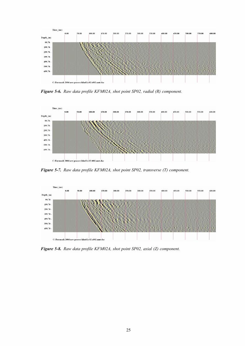
The data, from SP03, borehole KFM01A, shown in Figure 5-13, Figure 5-14 and Figure 5-15 present the profiles presented in Figure 5-10, Figure 5-11 and Figure 5-12 as enhanced by Image Point filtering using 27-traces panels.
The polarization information was also used to enhance the P-wave reflected field and to suppress S-wave conversions, which would be polarized perpendicularly to the direction of the P-waves. A brief description of the IP transform and the use of polarization analysis in the IP space are given in Appendix A. A non-linear coherency enhancement scheme (in the IP space) was also applied, the results for SP03, borehole KFM01A, being shown in Figure 5-16, Figure 5-17 and Figure 5-18.
Figure 5-10. Pre-processed profile KFM01A, shot point SP03, radial (R) component.
Figure 5-11. Pre-processed profile KFM01A, shot point SP03, transverse (T) component.
Figure 5-12. Pre-processed profile KFM01A, shot point SP03, axial (Z) component.
28
Figure 5-13. IP-filtered profile from KFM01A, shot point SP03, radial (R) component.
Figure 5-14. IP-filtered profile from KFM01A, shot point SP03, transversal (T) component.
Figure 5-15. IP-filtered profile from KFM01A, shot point SP03, axial (Z) component.

29
A few conclusions can be drawn by comparing the groups of graphs for raw data (Figure 5-2 to Figure 5-4), the preprocessed data (Figure 5-10 to Figure 5-12), the linear IP transform filtered data (Figure 5-13 to Figure 5-15) and the non-linearly filtered data (Figure 5-16 to Figure 5-18). These processing steps are subsequent, each being applied on the result of the previous. The pre-processing, which is a collection of largely standard operators, successfully eliminated the direct P- and S-waves but the low apparent velocities of some of the coherent patterns emerging after the processing sequence indicates their S-wave nature. Steeper reflectors may generate S-wave conversions with steeper apparent
Figure 5-16. Enhanced IP-filtered profile from KFM01A, SP03, radial (R) component.
Figure 5-17. Enhanced IP-filtered profile from KFM01A, SP03, transversal (T) comp.
Figure 5-18. Enhanced IP-filtered profile from KFM01A, SP03, axial (Z) component.

30
velocities, these being potentially mistakenly interpreted as genuine P-reflectors, with spurious orientations. The IP transform polarization filtering eliminates most of the S-wave conversions. Non-linear IP filtering conserves the major identifiable coherent patterns, i.e. reflections, and makes them easier to identify in the subsequent interactive interpretation stage. Therefore, non-linear IP filtering is in fact a means of data reduction meant to alleviate interpretation.

31
6 Interpretation of the VSP data measured from boreholes KFM01A and KFM02A
Due to the wide diversity of reflection angles, to the local variations of reflectivity and, generally, to the relatively weak seismic response of reflecting interfaces such as faults and fracture zones, the “importance” of a reflector cannot reliably be quantified based solely on the amplitude of the corresponding event in a time-depth profile. The VSP profiles measured in crystalline rock tend to display a relatively numerous collection of reflection events with similar amplitudes.
The “importance” of a reflector is assessed by evaluating its consistency amongst several profiles. Consistency may be interpreted as an indication of spatial extent and continuity. Each depth-time profile is a 2-D representation and does not contain sufficient information for the complete determination of the 3-D orientation and position of a reflector. The interpretation process consists of finding the link between reflected events likely to represent the same feature in different profiles. Several profiles need to concur to resolve the orientation problem /Cosma and Enescu, 2002b/.
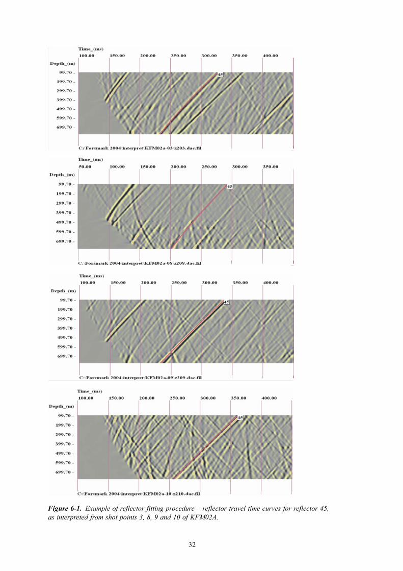
The reflector fitting procedure used with the Forsmark data is interactive and consists of superposing travel time functions on the reflection events. The travel time curves are displayed as coloured lines in Image Point filtered sections, see Figure 6-1. The depth of intersection in the receiver borehole (or its geometrical extension) and a dip – dip direction function best fitting the chosen trajectory are calculated. The dip and dip direction are varied according to the relation given by the fit and displayed as a stereographic projection. The dip and dip direction are determined by fitting amongst at least three different profiles, see Appendix A4.
For profiles measured in the same borehole the mean orientation of a reflector can be found in a stereographic representation (Wulff diagram – see Figure A-3 for a definition of the Wulff projection) at the intersection of the dip-dip direction curves computed for each profile, as shown in Figure 6-2. Each dip-azimuth curve (red) describes the possible orientations associated with the same time-depth function in a given profile. As fracture zones develop more or less along planes, their images in profiles measured with the same receiver layout are assumed to have the same intersection position along the layout and the stereographic projection is computed at this specific position. The intersection, the dip and the dip direction determine completely the position and orientation of a reflector. As the intersection is not exactly one point but a region, the “centre” of this region is determined by clustering analysis. The travel time curve computations are then performed in an inverse order, to determine in each profile the travel time function for the reflection plane corresponding to the just determined intersection point. The next stage is to allow variability in the fit, e.g. +/– half wavelength on each side of the predicted travel time function. The path of maximum signal energy/coherency is determined automatically within the interval allowed. For each interpreted reflector, a 3D reflector element is computed once the orientation of the reflector is completely determined. The stereographic representation method is not applicable to profiles measured in different boreholes because the intersection positions vary widely due to lateral extrapolation.
32
Figure 6-1. Example of reflector fitting procedure – reflector travel time curves for reflector 45, as interpreted from shot points 3, 8, 9 and 10 of KFM02A.

33
6.1 3D interpretation of reflectors from the VSP data acquired in borehole KFM01A
Figures 6-4 to 6-23 displays reflectors interpreted from the ten shot-points in borehole KFM01A. The results are discussed in chapter 7.
Figure 6-2. Wulff diagram for the interpretation of the orientation of reflector 45 determined from KFM02A.
Figure 6-3. Top view (left) and 3D view (right) of reflector elements of reflector 45, as determined from the VSP data acquired in KFM02A.

34
Figure 6-4. KFM01A. Maximum polarization component from SP01.
Figure 6-5. KFM01A. Reflectors interpreted from SP01.

35
Figure 6-6. KFM01A. Maximum polarization component from SP02.
Figure 6-7. KFM01A. Reflectors interpreted from SP02.

36
Figure 6-8. KFM01A. Maximum polarization component from SP03.
Figure 6-9. KFM01A. Reflectors interpreted from SP03.

37
Figure 6-10. KFM01A. Maximum polarization component from SP04.
Figure 6-11. Reflectors interpreted from SP04.

38
Figure 6-12. KFM01A. Maximum polarization component from SP05.
Figure 6-13. KFM01A. Reflectors interpreted from SP05.
39
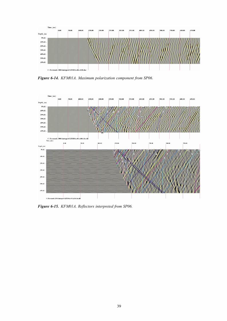
Figure 6-14. KFM01A. Maximum polarization component from SP06.
Figure 6-15. KFM01A. Reflectors interpreted from SP06.
40
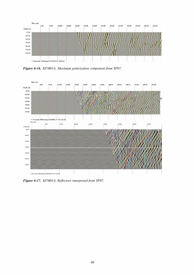
Figure 6-16. KFM01A. Maximum polarization component from SP07.
Figure 6-17. KFM01A. Reflectors interpreted from SP07.

41
Figure 6-18. KFM01A. Maximum polarization component from SP08.
Figure 6-19. KFM01A. Reflectors interpreted from SP08.

42
Figure 6-20. KFM01A. Maximum polarization component from SP09.
Figure 6-21. KFM01A. Reflectors interpreted from SP09.

43
6.2 3D interpretation of reflectors from the VSP data acquired in borehole KFM02A
The Figures 6-24 to 6-41 display reflectors interpreted from ten shot-points in borehole KFM02A. The results are discussed in chapter 7.
Figure 6-22. KFM01A. Maximum polarization component from SP10.
Figure 6-23. KFM01A. Reflectors interpreted from SP10.
44
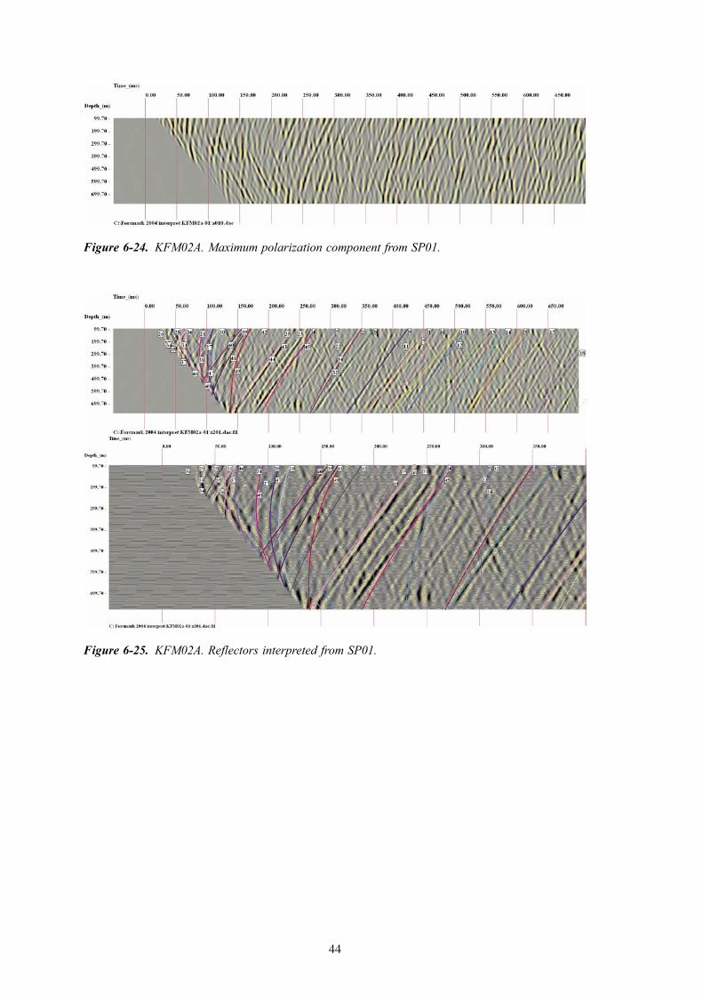
Figure 6-24. KFM02A. Maximum polarization component from SP01.
Figure 6-25. KFM02A. Reflectors interpreted from SP01.

45
Figure 6-26. KFM02A. Maximum polarization component from SP02.
Figure 6-27. KFM02A. Reflectors interpreted from SP02.

46
Figure 6-28. KFM02A. Maximum polarization component from SP03.
Figure 6-29. KFM02A. Reflectors interpreted from SP03.

47
Figure 6-30. KFM02A. Maximum polarization component from SP04.
Figure 6-31. KFM02A. Reflectors interpreted from SP04.

48
Figure 6-32. KFM02A. Maximum polarization component from SP06.
Figure 6-33. KFM02A. Reflectors interpreted from SP06.
49
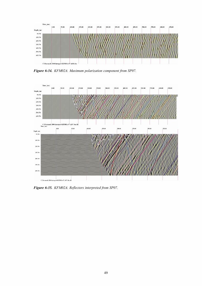
Figure 6-34. KFM02A. Maximum polarization component from SP07.
Figure 6-35. KFM02A. Reflectors interpreted from SP07.

50
Figure 6-36. KFM02A. Maximum polarization component from SP08.
Figure 6-37. KFM02A. Reflectors interpreted from SP08.
51
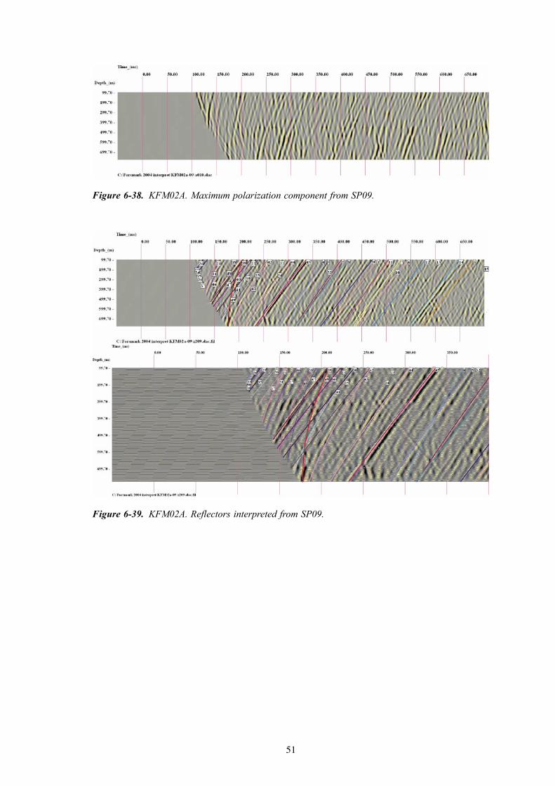
Figure 6-38. KFM02A. Maximum polarization component from SP09.
Figure 6-39. KFM02A. Reflectors interpreted from SP09.

52
6.4 NonconformitiesThe work has been executed according to the activity plan AP PF 400-04-60 in all aspects. There have been no nonconformities to note.
Figure 6-40. KFM02A. Maximum polarization component from SP10.
Figure 6-41. KFM02A. Reflectors interpreted from SP10.
53
7 Results
The first column in Table 7-1 (for KFM01A) and Table 7-2 and Table B-2 (for KFM02A) is the event number, which is the same as the label of the reflector curves shown in Figure 6-5 to Figure 6-23 (for KFM01A) and Figure 6-24 to Figure 6-41 (for KFM02A). The numbering of the reflectors has been done independently for the two boreholes. The extension of the reflective elements shown in the 3-D figures is 100 m, which corresponds to +/– two mean wavelengths.
The second column is the corresponding borehole length (or extension of the borehole length). This parameter is relevant for the interpretation of the reflectors that actually intersect the borehole. For the others, it is only a mathematical way of describing the position of the reflector relative to the borehole axis. The dips of the reflectors given in the third column and the dip directions in the fourth column were determined interactively, in several steps, as described in Chapter 6.
The last three columns give the coordinates of the crux point that, together with the coordinates of the origin chosen for interpretation (North = 6699000, East = 1633000; Elevation = 0), fully characterizes the reflector. Having a common origin facilitates further integration of interpreted reflectors, among several boreholes and with those interpreted from surface seismic profiles. A Crux Point is defined as the foot of the perpendicular descended on a given reflection plane from an origin common for all profiles.
Appendix B lists reflector parameters for each of the boreholes, as interpreted from each shot point. In addition to columns 1 to 4 and 5 to 7 (which are equivalent to 1 to 4 and 7 to 9 respectively) in Table 7-1 (for KFM01A) and Table 7-2 (for KFM02A), Table B-1 and Table B-2 also provide the “Visibility” (column 5), “Event type” (column 6) and “Shot point” (column 10).
In each profile, reflectors are classified in three categories. Major events, appearing as well defined and continuous, belong to the first category (visibility mark = 2 – marked with thick coloured line on the data profiles shown in Chapter 6). The weaker reflectors, visible but overridden by stronger events of other orientations belong to the second category (visibility mark = 1 – marked with thin coloured line on the data profiles shown in Chapter 6). If the position and orientation of an event are determined from other profiles but the event does not appear as visible in the current profile, it is categorized as a third class (visibility mark = 0 – marked with interrupted coloured line on the data profiles shown in Chapter 6). The parameters of the visibility = 0 events are not given in Table B-1 and Table B-2. The mean value of the visibility marks, calculated from all profiles, is given for each reflector in Table B-1 and Table B-2, on the lines marked in bold face fonts. Reflectors with a mean mark larger than 0.8 (the absolute maximum being 1.0) are classified as strong (class I). Reflectors with a mean mark between 0.5 and 0.75 are classified as probable (class II). The weak seismic reflectors, with mean marks lower than 0.45 are classified as possible (class III).
Interpreted reflectors appear on the VSP profiles as direct P reflections or P-S conversions. This is documented by the “Event type” given in column 6 of Table B-1 and Table B-2.

54
7.1 Parameters of reflectors interpreted from KFM01AThe reflectors interpreted from KFM01A are summarized in Table 7-1. The dip is measured from the horizontal. To arrive at RT90 coordinates, add 6600000 to the Northing values and 1600000 to the Easting values.
Table 7-1. VSP reflectors interpreted from borehole KFM01A.
Reflector label
Borehole length (m)
Dip (deg)
Dip direction (deg)
Reflector Class
Northing Crux
Easting Crux
Elevation Crux
1 194 38 124 II 99372 32426 –900
2 217 27 135 II 99285 32712 –788
3 267 54 142 I 99822 32338 –765
4 324 56 181 I 99500 33009 –336
5 392 49 178 I 99536 32982 –474
6 465 49 165 I 99740 32791 –679
7 523 48 171 I 99701 32866 –637
8 572 24 161 I 99354 32879 –857
9 626 21 145 I 99317 32775 –1,018
10 751 23 135 I 99352 32638 –1,195
11 770 38 172 I 99674 32907 –859
12 832 34 161 I 99697 32759 –1,079
13 940 36 167 I 99756 32828 –1,064
14 1,050 37 163 I 99861 32743 –1,180
15 1,246 35 151 I 99876 32524 –1,458
16 1,317 27 152 I 99700 32623 –1,594
17 1,551 42 135 I 100093 31917 –1,706
18 1,590 35 166 I 100070 32732 –1,552
19 1,941 41 164 I 100392 32597 –1,683
20 2,024 38 159 I 100365 32472 –1,888
21 265 64 216 I 98740 32809 155
22 351 63 237 II 98617 32409 363
23 675 70 234 I 98596 32450 245
24 2,803 82 238 II 98548 32288 116
25 882 59 243 I 98756 32522 321
26 1,087 65 220 I 98912 32926 54
27 3,036 78 226 I 98828 32821 52
28 2,025 69 229 I 98892 32874 63
29 1,621 60 226 I 99043 33044 –35
30 1,977 61 223 I 99166 33157 –124
31 2,371 61 234 I 99085 33116 –80
32 2,953 64 216 I 99584 33423 –350
33 153 34 200 II 99057 33007 –86
34 –18 32 187 II 99076 33003 –122
35 –1 32 194 III 99037 33009 –60
43 169 22 154 I 99199 32902 –551
45 311 35 172 I 99393 32937 –572
46 2,226 59 234 II 99100 33138 –104
49 913 61 207 III 99178 33090 –109
55
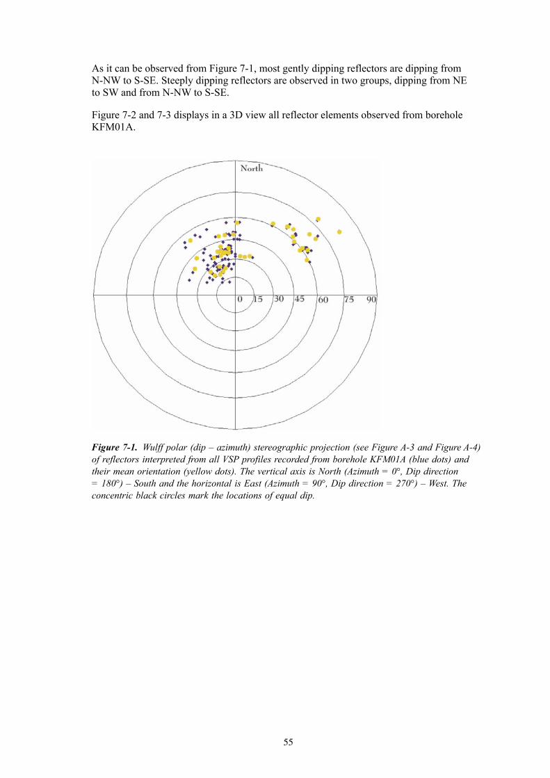
As it can be observed from Figure 7-1, most gently dipping reflectors are dipping from N-NW to S-SE. Steeply dipping reflectors are observed in two groups, dipping from NE to SW and from N-NW to S-SE.
Figure 7-2 and 7-3 displays in a 3D view all reflector elements observed from borehole KFM01A.
Figure 7-1. Wulff polar (dip – azimuth) stereographic projection (see Figure A-3 and Figure A-4) of reflectors interpreted from all VSP profiles recorded from borehole KFM01A (blue dots) and their mean orientation (yellow dots). The vertical axis is North (Azimuth = 0°, Dip direction = 180°) – South and the horizontal is East (Azimuth = 90°, Dip direction = 270°) – West. The concentric black circles mark the locations of equal dip.

56
Figure 7-2. 3D view of all reflector elements interpreted from the VSP data acquired in borehole KFM01A. View from Southwest.
Figure 7-3. 3D view of all reflector elements interpreted from the VSP data acquired in borehole KFM01A. View from Northwest.
57
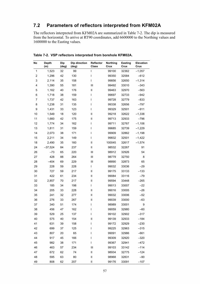
7.2 Parameters of reflectors interpreted from KFM02AThe reflectors interpreted from KFM02A are summarized in Table 7-2. The dip is measured from the horizontal. To arrive at RT90 coordinates, add 6600000 to the Northing values and 1600000 to the Easting values.
Table 7-2. VSP reflectors interpreted from borehole KFM02A.
No Depth (m)
Dip (deg)
Dip direction (deg)
Reflector Class
Northing Crux
Easting Crux
Elevation Crux
1 1,523 32 99 I 99100 32362 –1,0572 1,296 42 130 I 99350 32584 –6123 2,114 35 158 I 99856 32650 –1,3144 1,390 55 181 III 99492 33010 –3435 1,162 40 176 II 99463 32970 –5636 1,718 38 159 I 99697 32733 –9427 1,737 42 163 I 99728 32779 –8338 1,238 31 135 I 99338 32656 –7979 1,431 33 123 I 99329 32501 –911
10 1,549 18 120 II 99218 32622 –1,33811 1,660 42 175 II 99713 32933 –79612 1,774 34 162 I 99711 32767 –1,10613 1,811 31 159 I 99685 32739 –1,22914 2,073 38 171 I 99909 32862 –1,19815 2,211 34 149 I 99832 32501 –1,42218 2,490 35 160 II 100045 32617 –1,57424 –37,524 84 237 II 98532 32267 9126 –73 65 220 III 98912 32926 5427 428 88 264 III 98779 32750 828 –404 69 229 III 98890 32873 6529 228 59 228 I 99032 33036 –2930 727 59 217 II 99175 33133 –13331 422 61 234 II 99084 33116 –7932 2,857 70 217 II 99594 33448 –26533 185 34 198 I 99013 33007 –2234 205 33 228 II 99016 33005 –2635 241 32 277 II 99032 33006 –5236 276 33 267 II 99039 33000 –6337 340 51 174 I 98989 33001 938 456 47 162 I 99059 32980 –6039 529 25 137 I 99102 32902 –31740 575 40 154 II 99139 32933 –18441 631 39 158 I 99172 32929 –23042 699 37 125 I 99225 32963 –31543 807 20 65 I 99091 32986 –66144 917 45 166 I 99309 32920 –32045 982 38 171 I 99367 32941 –47246 463 57 234 III 99103 33142 –11447 672 62 74 II 98934 32775 –12448 595 63 80 II 98968 32831 –9049 808 62 207 II 99176 33091 –107

58
As it can be observed from Figure 7-4, most gently dipping reflectors are dipping from N-NW to S-SE. Steeply dipping reflectors are observed in two groups, dipping from NE to SW and from N-NW to S-SE.
Figure 7-5 and 7-6 displays in a 3D view all reflector elements observed from borehole KFM02A.
Figure 7-4. Wulff polar (dip – azimuth) stereographic projection (see Figure A-3 and Figure A-4) of reflectors interpreted from all VSP profiles recorded from borehole KFM02A (dark blue dots) and their mean orientation (light blue dots). The vertical axis is North (Azimuth = 0°, Dip direction = 180°) – South and the horizontal is East (Azimuth = 90°, Dip direction = 270°) – West. The concentric black circles mark the locations of equal dip.

59
Figure 7-5. 3D view of all reflector elements interpreted from the VSP data acquired in borehole KFM02A. View from Southwest.
Figure 7-6. 3D view of all reflector elements interpreted from the VSP data acquired in borehole KFM02A. View from Northwest.
60
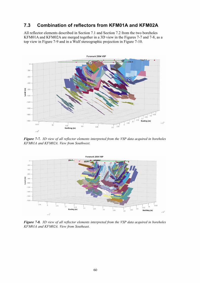
7.3 Combination of reflectors from KFM01A and KFM02AAll reflector elements described in Section 7.1 and Section 7.2 from the two boreholes KFM01A and KFM02A are merged together in a 3D view in the Figures 7-7 and 7-8, as a top view in Figure 7-9 and in a Wulf stereographic projection in Figure 7-10.
Figure 7-7. 3D view of all reflector elements interpreted from the VSP data acquired in boreholes KFM01A and KFM02A. View from Southwest.
Figure 7-8. 3D view of all reflector elements interpreted from the VSP data acquired in boreholes KFM01A and KFM02A. View from Southeast.

61
Figure 7-9. Top view of all reflector elements interpreted from the VSP data acquired in boreholes KFM01A and KFM02A.
Figure 7-10. Wulff polar (dip – azimuth) stereographic projection of reflectors interpreted from all VSP profiles recorded from boreholes KFM01A and KFM02A (dark blue dots) and their mean orientation (yellow for KFM01A and light blue dots for KFM02A). The vertical axis is North (Azimuth = 0°, Dip direction = 180°) – South and the horizontal is East (Azimuth = 90°, Dip direction = 270°) – West. The concentric black circles mark the locations of equal dip.
63
References
Cosma C, 1990. Seismic Imaging Techniques Applied to Rock Engineering. Invited paper. Proceedings of The 1st SEGJ International Symposium on Geotomography, Tokyo, Japan.
Cosma C, Heikkinen P J, Keskinen J, 1994a. Development of seismic investigation techniques, Part I: Coverage analysis of VSP surveys. TVO, Helsinki. Work report PATU-94-02e.
Cosma C, Heikkinen P J, Keskinen J, 1994b. Development of seismic investigation techniques, Part II: Site coverage of VSP surveys in Romuvaara, borehole KR2. TVO, Helsinki. Work report PATU -94-03e.
Cosma C, 1995. Characterisation of subsurface structures by remote sensing. Keynote address. Proceedings of the 1st International Congress on Rock Mechanics (ISRM), Tokyo, Japan.
Cosma C, Heikkinen P, 1996. Seismic Investigations for the Final Disposal of Spent Nuclear Fuel in Finland. Journal of Applied Geophysics vol. 35, pp 151–157.
Cosma C, Heikkinen P J, Keskinen J, Enescu N, 2001a. VSP in Crystalline Rocks – from Downhole Velocity Profiling to 3-D Fracture Mapping. International Journal of Rock Mechanics and Mining Sciences, vol. 38, no 6, pp.
Cosma C, Olsson O, Keskinen J, Heikkinen P J, 2001b. Seismic characterisation of fracturing at the Äspö Hard Rock Laboratory, from the kilometre scale to the meter scale. International Journal of Rock Mechanics and Mining Sciences, vol. 38, 6, pp.
Cosma C, Enescu N, 2001. Characterization of Fractured Rock in the Vicinity of Tunnels by the Swept Impact Seismic Technique. International Journal of Rock Mechanics and Mining Sciences, vol. 38, no 6, pp 815–821.
Cosma C, Enescu N, Keskinen J, 2002a. Vertical Seismic Profiling from KLX-02, Laxemar, 2000. SKB Technical Document, TD-02-02, Svensk Kärnbränslehantering AB.
Cosma C, Enescu N, 2002b. Multi-Azimuth VSP Methods for Fractured Rock Characterization, the 5th ISRM Conference, Toronto.
Enescu N, Cosma C, 1999. VSP Investigations for the Malmö City Tunnel project. Work report, DGI, Denmark.
Heikkinen P J, Cosma C, 1994. Development of seismic investigation techniques. Part III: Fast 3D-modeling of VSP surveys. TVO site investigations, Work report PATU-94-04e.
Heikkinen P J, Cosma C, Keskinen J, 1995. Development of Seismic Investigation Techniques: Anisotropy in VSP Measurements. Work Report PATU-95-58e.
Juhlin C, Bergman B, Cosma C, Keskinen J, Enescu N, 2002. Vertical Seismic Profiling and Integration with Reflection Seismic Studies at Laxemar, 2000. SKB TR-02-04, Svensk Kärnbränslehantering AB.

64
Juhlin C, Bergman B, 2004. Reflection seismics in the Forsmark area – Updated interpretation of Stage 1 (previous report R-02-43) – Updated estimate of the bedrock topography (previous report P-04-99). SKB P-04-158, Svensk Kärnbränslehantering AB.
Keskinen J, Cosma C, Enescu N, 1999. Seismic Investigations at the Gletchel Mine, Winnemucca, Nevada. Work report, PlacerDome, USA.
Keskinen J, Cosma C, Enescu N, 2000. VSP Structural Survey at the Onaping Depths in Sudbury. Work report, Falconbridge Limited, Canada.
Park C B, Miller R D, Steeples D W, Black R A, 1996. Swept Impact Seismic Technique (SIST). Geophysics, vol. 61, no 6, pp 1,789–1,803.
65
Appendix A
A.1 The Image Point (IP) transform
The IP (Image Point) forms the core of the technique that we have developed for filtering crystalline rock VSP and cross-hole data. The Radon transforms have been applied to seismic data in many ways, e.g. slant stack τ-p transform, where the apparent velocity limits are varied according to the predicted travel times of reflections. Unlike with the τ-p, with the IP transform the stacking is done along hyperbolic paths corresponding to the time-depth functions of possible reflectors. Due to this ”natural” choice of the stacking paths, the coherency can be used effectively to enhance the weak reflections. Other advantages of the IP transform include the efficient separation of interfering reflections and the possibility of using directly the IP transformed profiles as interpretation tools.
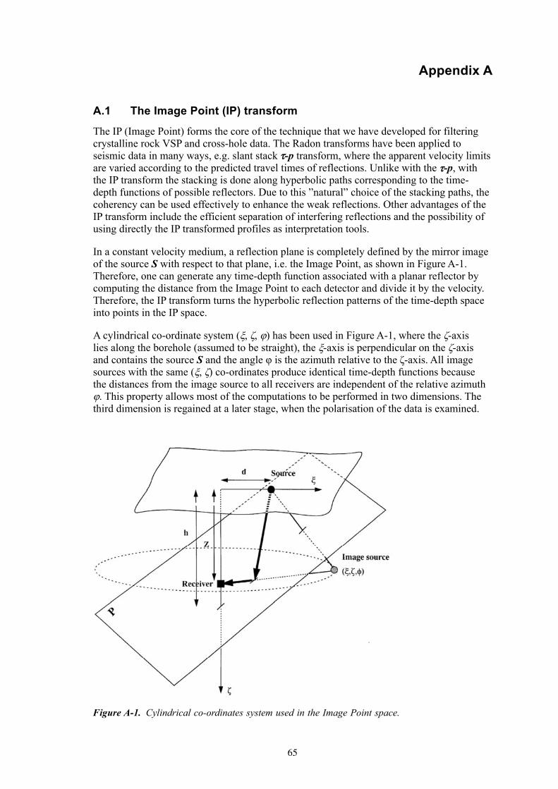
In a constant velocity medium, a reflection plane is completely defined by the mirror image of the source S with respect to that plane, i.e. the Image Point, as shown in Figure A-1. Therefore, one can generate any time-depth function associated with a planar reflector by computing the distance from the Image Point to each detector and divide it by the velocity. Therefore, the IP transform turns the hyperbolic reflection patterns of the time-depth space into points in the IP space.
A cylindrical co-ordinate system (ξ, ζ, φ) has been used in Figure A-1, where the ζ-axis lies along the borehole (assumed to be straight), the ξ-axis is perpendicular on the ζ-axis and contains the source S and the angle φ is the azimuth relative to the ζ-axis. All image sources with the same (ξ, ζ) co-ordinates produce identical time-depth functions because the distances from the image source to all receivers are independent of the relative azimuth φ. This property allows most of the computations to be performed in two dimensions. The third dimension is regained at a later stage, when the polarisation of the data is examined.
Figure A-1. Cylindrical co-ordinates system used in the Image Point space.

66
The time-depth function of a reflected event in a time-depth profile is
( )( ) vzzvztr ζζξζξ 222222 −++=−+= (A.1)
where tr is the travel time to the receiver placed at depth z, v is the constant propagation velocity and (ξ, ζ) are the co-ordinates of the Image Source.
Equation (A.1) becomes
vzztr ζρ 222 −+= (A.2)
by replacing the variable ξ with
22 ζξρ += (A.3)
If the distance ρ from the origin is used instead of the offset ξ, the transformed representation will not be stretched and easier to use as an interpretive tool. The travel time does not depend on the relative azimuth φ, i.e. the locus of possible image points forms a circle centred on the borehole.
The Image Point transformed profile Γ(ρ, ζ) is obtained by stacking in the time-depth profile g(z, t) along paths corresponding to all (ρ, ζ) pairs within a selected domain ρmin ≤ ρ ≤ ρmax, ζmin ≤ ζ ≤ ζmax, thus covering all possible positions and orientations that a reflecting plane may have:
Γ ( , ) ( , ( , ; ))min
max
ζ ρ ζ ρ= =∫ dz g z t t zrZ
Z
(A.4)
where tr(ζ, ρ; z) is the arrival time corresponding to the planar reflector specified by ρ and ζ, to the detector at depth z.
The inverse transform is constructed by integrating along each path that received the contribution of g(z, t) in the direct transform:
));,(;(2
1),(
2
1
2ζρρζζ
∂∂
π
ζ
ζ
tzdttv
tzg r∫ =Γ⋅⋅
= H (A.5)
where
ζρ zztvr 2222 +−= (A.6)
The Hilbert transform H and the derivation with respect to time are used to restore the original signal shape, similarly as with the τ-p transform.
The inverse transform from Image Space back to depth-time space leads to a filtered version of the reflection profile. This filtering effect cannot be avoided, as the summing is done only along paths corresponding to time functions of true reflected signals travelling with the velocity v. These events stack properly while noise and other wave types are suppressed.
A.2 Polarisation analysis in the Image Point space
The (ρ, ζ) co-ordinates of the Image Point space define two of the three parameters needed to determine the 3-D position of a reflector (the azimuth φ relative to the ζ-axis plays no role in the IP transform).
67
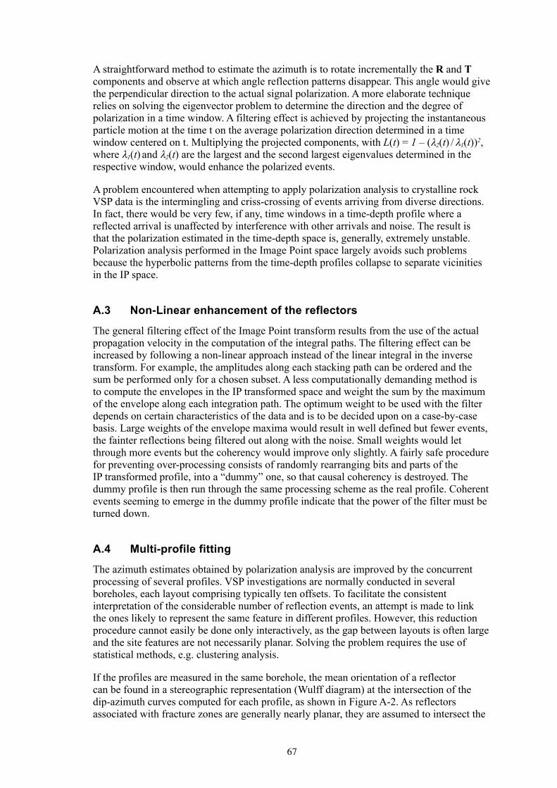
A straightforward method to estimate the azimuth is to rotate incrementally the R and T components and observe at which angle reflection patterns disappear. This angle would give the perpendicular direction to the actual signal polarization. A more elaborate technique relies on solving the eigenvector problem to determine the direction and the degree of polarization in a time window. A filtering effect is achieved by projecting the instantaneous particle motion at the time t on the average polarization direction determined in a time window centered on t. Multiplying the projected components, with L(t) = 1 – (λ2(t) / λ1(t))2, where λ1(t) and λ2(t) are the largest and the second largest eigenvalues determined in the respective window, would enhance the polarized events.
A problem encountered when attempting to apply polarization analysis to crystalline rock VSP data is the intermingling and criss-crossing of events arriving from diverse directions. In fact, there would be very few, if any, time windows in a time-depth profile where a reflected arrival is unaffected by interference with other arrivals and noise. The result is that the polarization estimated in the time-depth space is, generally, extremely unstable. Polarization analysis performed in the Image Point space largely avoids such problems because the hyperbolic patterns from the time-depth profiles collapse to separate vicinities in the IP space.
A.3 Non-Linear enhancement of the reflectors
The general filtering effect of the Image Point transform results from the use of the actual propagation velocity in the computation of the integral paths. The filtering effect can be increased by following a non-linear approach instead of the linear integral in the inverse transform. For example, the amplitudes along each stacking path can be ordered and the sum be performed only for a chosen subset. A less computationally demanding method is to compute the envelopes in the IP transformed space and weight the sum by the maximum of the envelope along each integration path. The optimum weight to be used with the filter depends on certain characteristics of the data and is to be decided upon on a case-by-case basis. Large weights of the envelope maxima would result in well defined but fewer events, the fainter reflections being filtered out along with the noise. Small weights would let through more events but the coherency would improve only slightly. A fairly safe procedure for preventing over-processing consists of randomly rearranging bits and parts of the IP transformed profile, into a “dummy” one, so that causal coherency is destroyed. The dummy profile is then run through the same processing scheme as the real profile. Coherent events seeming to emerge in the dummy profile indicate that the power of the filter must be turned down.
A.4 Multi-profile fitting
The azimuth estimates obtained by polarization analysis are improved by the concurrent processing of several profiles. VSP investigations are normally conducted in several boreholes, each layout comprising typically ten offsets. To facilitate the consistent interpretation of the considerable number of reflection events, an attempt is made to link the ones likely to represent the same feature in different profiles. However, this reduction procedure cannot easily be done only interactively, as the gap between layouts is often large and the site features are not necessarily planar. Solving the problem requires the use of statistical methods, e.g. clustering analysis.
If the profiles are measured in the same borehole, the mean orientation of a reflector can be found in a stereographic representation (Wulff diagram) at the intersection of the dip-azimuth curves computed for each profile, as shown in Figure A-2. As reflectors associated with fracture zones are generally nearly planar, they are assumed to intersect the

68
borehole (or its extension) at the same depth. The stereographic representation method is not applicable to profiles measured in different boreholes because the intersection positions vary widely due to lateral extrapolation. The 3D fitting procedure exemplified in Figure A-5 is applied instead. The curves in Figure A-6 are described by the foot of the perpendicular descended on a given reflection plane from chosen origin, common for all profiles.
Figure A-2. Different shot gathers filtered by the IP transform.
Figure A-3. The Wulff equal-angle stereographic projection of a reflector is given by the intersection of the segment drawn between the North Pole (P) and the point on the lower hemisphere, which has the coordinates equal to the dip and azimuth of the reflector element with the Equatorial plane. Azimuth = Dip direction +180°.
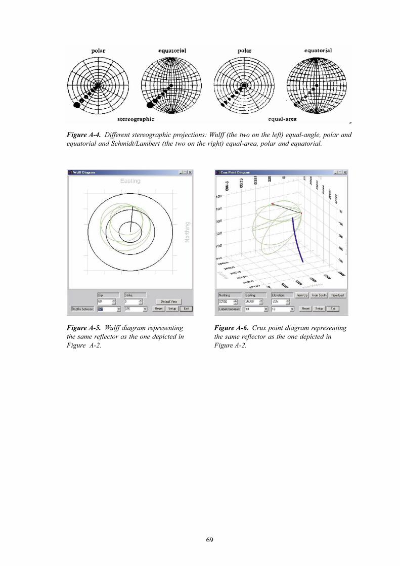
69
Figure A-4. Different stereographic projections: Wulff (the two on the left) equal-angle, polar and equatorial and Schmidt/Lambert (the two on the right) equal-area, polar and equatorial.
Figure A-5. Wulff diagram representing the same reflector as the one depicted in Figure A-2.
Figure A-6. Crux point diagram representing the same reflector as the one depicted in Figure A-2.

71
Appendix B
Detailed description of all reflectors observed from KFM01A (Table B-1) and from KFM02A (Table B-2). The dip is measured from the horizontal. To arrive at RT90 coordinates, add 6600000 to the Northing values and 1600000 to the Easting values.
Table B-1. Geometrical parameters of reflectors interpreted from VSP data acquired in borehole KFM01A. The lines written in bold fonts give the mean values for each parameter, as computed for each reflector.
No Borehole length (m)
Dip (°) Dip dir (°)
Visibility marks
Event type Delta depth (m)
Delta Dip (°)
Delta Dip dir (°)
Shot point
1 194.3 37.8 118.9 1 P reflection 43.4 25.9 35.0 KFM01A-01
1 194.3 37.8 118.9 2 PS conversion 15.1 20.0 161.5 KFM01A-02
1 194.3 37.8 118.9 2 P reflection 13.6 18.7 33.7 KFM01A-03
1 194.3 37.8 118.9 2 P reflection 17.7 10.0 67.4 KFM01A-04
1 194.4 37.8 148.9 2 P reflection 13.9 1.3 25.7 KFM01A-05
1 194.5 37.8 108.9 2 P reflection 21.6 20.6 57.1 KFM01A-06
1 194.3 37.8 118.9 2 P reflection 20.5 16.2 45.0 KFM01A-07
1 194.4 37.8 138.9 2 P reflection 21.5 16.5 44.9 KFM01A-08
1 194.3 37.8 118.9 1 P reflection 86.4 37.8 61.1 KFM01A-09
1 194.3 37.8 118.9 1 P reflection 113.4 46.7 91.0 KFM01A-10
1 194.3 37.8 122.9 0.85 13.6 1.3 25.72 217.2 25.0 134.4 2 P reflection 25.6 17.1 85.0 KFM01A-02
2 217.2 25.0 134.4 2 P reflection 11.4 16.0 43.6 KFM01A-03
2 217.2 31.0 134.4 2 P reflection 13.5 1.1 50.8 KFM01A-04
2 217.2 29.6 144.4 2 P reflection 13.4 6.5 21.1 KFM01A-05
2 217.4 25.0 125.0 2 P reflection 18.9 29.3 39.7 KFM01A-06
2 217.3 25.0 135.0 2 P reflection 19.8 30.7 29.8 KFM01A-07
2 217.2 29.6 134.4 2 P reflection 22.7 30.7 49.5 KFM01A-08
2 217.2 27.2 134.6 0.7 11.4 1.1 21.13 267.0 53.0 135.0 2 PS conversion 24.6 11.3 78.1 KFM01A-02
3 267.0 53.0 135.0 2 PS conversion 11.8 36.4 14.4 KFM01A-03
3 267.0 53.0 135.0 2 P reflection 19.7 1.7 49.9 KFM01A-04
3 267.0 55.7 147.4 2 P reflection 15.8 6.4 2.6 KFM01A-05
3 267.6 55.7 137.4 2 P reflection 16.6 6.0 25.9 KFM01A-06
3 266.9 55.7 157.4 2 P reflection 16.3 13.3 0.7 KFM01A-07
3 267.0 53.0 150.0 2 P reflection 18.9 1.9 33.3 KFM01A-08
3 267.0 55.7 137.4 1 PS conversion 398.4 55.7 42.6 KFM01A-09
3 267.0 55.7 137.4 2 PS conversion 18.9 18.2 85.3 KFM01A-10
3 267.0 54.5 141.3 0.9 11.8 1.7 0.74 323.9 57.0 183.2 2 PS conversion 18.1 21.0 24.4 KFM01A-02
4 323.9 57.0 183.2 2 PS conversion 17.8 18.5 15.1 KFM01A-03
4 323.9 57.0 183.2 2 P reflection 18.8 3.9 0.4 KFM01A-04
4 323.9 57.0 183.2 2 P reflection 25.4 9.6 29.5 KFM01A-05
4 324.4 57.0 173.2 2 P reflection 16.7 3.5 7.9 KFM01A-06
4 323.9 57.0 183.2 2 P reflection 18.4 0.8 17.1 KFM01A-07
4 324.1 57.0 180.0 2 P reflection 17.0 5.9 2.8 KFM01A-08
4 324.2 50.0 180.0 2 P reflection 24.6 50.0 0.0 KFM01A-09

72
4 323.9 57.0 183.2 2 P reflection 23.9 2.0 23.0 KFM01A-10
4 324.0 56.2 181.4 0.9 16.7 0.8 0.05 391.9 48.9 178.6 2 PS conversion 894.2 18.4 127.3 KFM01A-01
5 391.9 48.9 178.6 2 P reflection 30.8 1.4 25.0 KFM01A-02
5 391.9 48.9 178.6 2 P reflection 21.8 2.5 7.6 KFM01A-03
5 391.9 50.0 178.0 2 P reflection 15.7 3.5 3.4 KFM01A-04
5 392.0 45.0 178.6 2 P reflection 17.3 9.7 26.6 KFM01A-05
5 392.4 48.9 178.6 2 P reflection 15.1 0.3 14.7 KFM01A-06
5 391.9 48.9 178.6 2 P reflection 15.7 0.2 15.6 KFM01A-07
5 391.8 48.0 175.0 2 P reflection 14.7 8.8 6.9 KFM01A-08
5 391.9 48.9 178.6 2 P reflection 26.4 48.9 1.4 KFM01A-09
5 391.9 48.9 178.6 2 P reflection 22.8 7.4 27.3 KFM01A-10
5 391.9 48.5 178.2 1.0 14.7 0.2 1.46 464.6 40.0 161.9 2 PS conversion 5,540.9 49.0 124.8 KFM01A-01
6 464.6 49.0 161.9 2 P reflection 27.7 2.1 37.9 KFM01A-02
6 464.6 49.0 161.9 2 P reflection 19.6 4.3 9.2 KFM01A-03
6 464.6 49.0 161.9 2 P reflection 15.6 3.1 18.4 KFM01A-04
6 464.6 49.0 161.9 2 P reflection 15.4 0.8 10.1 KFM01A-05
6 465.6 49.0 161.9 2 P reflection 13.9 5.3 0.3 KFM01A-06
6 464.6 49.0 171.9 2 P reflection 14.9 2.8 9.7 KFM01A-07
6 464.6 49.0 161.9 2 P reflection 15.0 1.7 19.7 KFM01A-08
6 464.6 45.0 182.0 2 P reflection 19.2 45.0 2.0 KFM01A-09
6 464.6 49.0 161.9 2 P reflection 26.4 15.5 41.9 KFM01A-10
6 464.7 47.7 164.9 1.0 13.9 0.8 0.37 522.5 48.9 164.1 2 P reflection 26.9 1.0 32.6 KFM01A-02
7 522.5 48.9 164.1 2 P reflection 19.6 3.6 7.3 KFM01A-03
7 522.5 48.9 164.1 2 P reflection 15.7 2.9 15.5 KFM01A-04
7 522.5 48.9 164.1 2 P reflection 15.6 1.4 10.7 KFM01A-05
7 523.6 48.9 174.1 2 P reflection 14.3 0.9 9.5 KFM01A-06
7 522.5 48.0 184.1 2 P reflection 15.6 4.4 18.9 KFM01A-07
7 522.5 48.9 174.1 2 P reflection 14.4 3.8 7.0 KFM01A-08
7 522.5 45.0 184.1 2 P reflection 19.9 45.0 4.1 KFM01A-09
7 522.5 48.9 164.1 2 P reflection 25.8 13.5 39.2 KFM01A-10
7 522.7 48.4 170.7 0.9 14.3 0.9 4.18 553.6 12.0 157.1 2 P reflection 20.7 12.9 73.0 KFM01A-01
8 573.6 24.8 157.1 1 P reflection 12.6 1.2 34.4 KFM01A-02
8 573.6 24.8 157.1 2 P reflection 11.3 4.2 0.7 KFM01A-03
8 573.6 24.8 157.1 2 P reflection 10.8 7.7 12.4 KFM01A-04
8 573.6 24.0 157.1 2 P reflection 11.5 6.2 20.5 KFM01A-05
8 574.0 24.8 167.1 2 P reflection 12.6 7.6 12.1 KFM01A-06
8 573.6 26.0 177.1 2 P reflection 14.2 19.7 14.6 KFM01A-07
8 573.6 24.8 167.1 2 P reflection 12.9 6.2 12.6 KFM01A-08
8 573.6 24.8 167.1 2 P reflection 16.3 24.8 12.9 KFM01A-09
8 573.6 24.8 150.0 2 P reflection 21.4 34.0 53.0 KFM01A-10
8 571.7 23.6 161.4 1.0 10.8 1.2 0.79 666.2 17.0 143.5 2 P reflection 19.5 9.6 76.0 KFM01A-01
9 626.2 21.2 143.5 2 P reflection 11.9 1.1 45.8 KFM01A-02
9 626.2 21.2 143.5 1 P reflection 10.7 6.2 4.9 KFM01A-03
9 626.2 21.2 143.5 2 P reflection 10.6 8.8 19.9 KFM01A-04

73
9 626.2 22.0 145.0 2 P reflection 11.0 2.0 21.5 KFM01A-05
9 626.7 21.2 143.5 2 P reflection 12.6 14.7 15.2 KFM01A-06
9 626.2 21.2 143.5 2 P reflection 14.2 25.9 20.1 KFM01A-07
9 626.2 21.2 143.5 2 P reflection 13.7 22.4 36.8 KFM01A-08
9 626.2 21.2 153.5 2 P reflection 18.0 21.2 26.5 KFM01A-09
9 626.2 21.2 143.5 2 P reflection 22.3 37.5 58.9 KFM01A-10
9 630.3 20.9 144.7 1.0 10.6 1.1 4.910 750.9 15.0 135.0 2 P reflection 15.2 6.6 82.0 KFM01A-01
10 750.0 27.0 134.3 2 P reflection 12.7 0.8 50.7 KFM01A-02
10 750.0 27.0 134.3 2 P reflection 11.3 5.8 24.7 KFM01A-03
10 750.9 22.0 135.0 2 P reflection 10.7 3.4 32.5 KFM01A-04
10 750.9 25.0 145.0 2 P reflection 10.8 3.1 21.5 KFM01A-05
10 751.5 25.0 115.0 2 P reflection 12.9 17.2 48.5 KFM01A-06
10 750.9 22.0 155.0 2 P reflection 13.1 18.7 5.9 KFM01A-07
10 750.9 22.0 125.0 2 P reflection 14.1 24.9 55.0 KFM01A-08
10 750.9 23.0 135.0 2 P reflection 17.4 23.0 45.0 KFM01A-09
10 750.9 22.0 135.0 2 P reflection 20.2 35.6 66.1 KFM01A-10
10 750.8 23.0 134.9 1.0 10.7 0.8 5.911 770.0 38.3 174.8 2 PS conversion 19.1 29.5 119.9 KFM01A-01
11 770.0 38.3 174.8 2 P reflection 15.6 1.7 11.4 KFM01A-02
11 770.0 38.3 174.8 2 P reflection 14.9 1.0 5.6 KFM01A-03
11 770.1 38.3 174.8 2 P reflection 13.0 2.0 0.6 KFM01A-04
11 770.1 38.3 174.8 2 P reflection 13.9 5.5 19.8 KFM01A-05
11 770.9 38.3 174.8 2 P reflection 12.5 0.7 12.9 KFM01A-06
11 770.1 40.0 174.8 2 P reflection 13.2 1.6 13.2 KFM01A-07
11 770.0 38.3 164.8 2 P reflection 12.5 2.6 13.7 KFM01A-08
11 770.1 38.3 174.8 2 P reflection 15.6 38.3 5.3 KFM01A-09
11 770.1 38.3 162.0 2 P reflection 17.8 14.4 39.3 KFM01A-10
11 770.1 38.5 172.5 1.0 12.5 0.7 0.612 831.4 31.0 160.6 2 P reflection 21.3 5.9 48.5 KFM01A-01
12 831.4 34.9 160.6 2 P reflection 14.1 1.8 23.6 KFM01A-02
12 831.4 34.0 160.6 2 P reflection 12.8 2.9 5.9 KFM01A-03
12 831.4 34.9 160.6 2 P reflection 12.0 3.0 13.0 KFM01A-04
12 831.4 34.9 160.6 2 P reflection 12.1 0.8 10.0 KFM01A-05
12 832.5 34.9 160.6 2 P reflection 11.7 7.3 7.5 KFM01A-06
12 831.4 34.9 170.6 2 P reflection 12.5 2.5 15.4 KFM01A-07
12 831.4 34.9 160.6 2 P reflection 12.2 2.4 17.0 KFM01A-08
12 831.4 34.9 160.6 2 P reflection 15.9 34.9 19.4 KFM01A-09
12 831.4 34.9 155.0 2 P reflection 17.7 17.8 45.5 KFM01A-10
12 831.6 34.4 161.1 1.0 11.7 0.8 5.913 939.5 34.0 169.4 2 P reflection 20.2 3.1 35.5 KFM01A-01
13 939.5 30.0 169.4 2 P reflection 12.4 2.6 11.8 KFM01A-02
13 939.5 34.0 169.4 2 P reflection 12.8 1.9 2.3 KFM01A-03
13 939.5 37.4 169.4 2 P reflection 12.5 2.6 4.6 KFM01A-04
13 939.5 37.4 169.4 2 P reflection 12.8 2.3 14.2 KFM01A-05
13 940.7 37.4 169.4 2 P reflection 11.9 2.2 8.6 KFM01A-06
13 939.5 38.0 169.4 2 P reflection 12.4 2.4 10.6 KFM01A-07
13 939.5 38.0 159.4 2 P reflection 12.2 2.0 18.2 KFM01A-08
13 939.5 37.4 169.4 2 P reflection 14.8 37.4 10.6 KFM01A-09

74
13 939.5 37.4 160.0 2 P reflection 16.3 12.2 39.6 KFM01A-10
13 939.6 36.1 167.4 1.0 11.9 1.9 2.314 1,049.8 37.6 163.8 2 P reflection 20.8 2.3 38.0 KFM01A-01
14 1,049.8 37.6 163.8 2 P reflection 13.9 2.5 17.6 KFM01A-02
14 1,049.8 35.0 163.8 2 P reflection 12.7 2.8 3.5 KFM01A-03
14 1,049.8 37.6 163.8 2 P reflection 12.3 3.1 9.6 KFM01A-04
14 1,049.8 37.6 163.8 2 P reflection 12.4 0.0 8.7 KFM01A-05
14 1,051.3 37.6 163.8 2 P reflection 11.7 4.0 3.6 KFM01A-06
14 1,049.8 37.6 163.8 2 P reflection 12.1 7.4 9.2 KFM01A-07
14 1,049.8 37.6 163.8 2 P reflection 12.0 3.5 12.8 KFM01A-08
14 1,049.8 37.6 163.8 2 P reflection 14.7 37.5 16.2 KFM01A-09
14 1,049.8 37.6 160.0 2 P reflection 15.5 10.1 38.6 KFM01A-10
14 1,050.0 37.3 163.4 1.0 11.7 0.0 3.515 1,205.2 27.2 148.5 2 P reflection 14.4 0.1 47.0 KFM01A-01
15 1,232.2 31.5 148.7 2 P reflection 12.1 3.5 28.9 KFM01A-02
15 1,232.2 35.0 148.7 2 P reflection 12.1 4.8 17.7 KFM01A-03
15 1,257.4 38.0 168.9 2 P reflection 12.4 2.8 4.1 KFM01A-04
15 1,232.2 31.5 148.7 2 P reflection 11.1 4.3 0.9 KFM01A-05
15 1,302.5 43.9 167.5 2 P reflection 12.5 2.5 2.1 KFM01A-06
15 1,299.5 43.9 147.5 2 P reflection 12.3 4.3 15.4 KFM01A-07
15 1,232.2 31.5 148.7 2 P reflection 11.5 1.4 26.2 KFM01A-08
15 1,232.2 33.0 138.7 2 P reflection 14.6 33.0 41.4 KFM01A-09
15 1,232.3 31.5 148.7 2 P reflection 14.5 13.2 48.2 KFM01A-10
15 1,245.8 34.7 151.4 1.0 11.1 0.1 0.916 1,316.4 26.2 149.0 2 P reflection 13.5 1.1 43.7 KFM01A-01
16 1,316.3 26.2 149.0 2 P reflection 11.3 4.4 25.4 KFM01A-02
16 1,316.3 30.0 149.0 2 P reflection 11.3 5.1 13.9 KFM01A-03
16 1,316.4 26.2 169.0 2 P reflection 10.8 4.2 2.8 KFM01A-04
16 1,316.4 26.2 149.0 2 P reflection 10.7 5.0 10.6 KFM01A-05
16 1,317.7 26.2 159.0 2 P reflection 10.8 4.1 9.1 KFM01A-06
16 1,316.4 26.2 149.0 2 P reflection 11.3 0.5 3.8 KFM01A-07
16 1,316.4 26.2 149.0 2 P reflection 11.1 5.5 22.0 KFM01A-08
16 1,316.4 26.2 149.0 2 P reflection 12.5 26.2 31.0 KFM01A-09
16 1,316.4 26.2 149.0 2 P reflection 13.3 13.0 47.7 KFM01A-10
16 1,316.5 26.6 152.0 1.0 10.7 0.5 2.817 1,551.0 42.1 134.3 2 P reflection 17.8 1.3 57.1 KFM01A-01
17 1,551.0 42.1 134.3 2 P reflection 13.8 3.7 44.0 KFM01A-02
17 1,551.0 42.1 134.3 2 P reflection 13.0 5.8 35.0 KFM01A-03
17 1,551.0 42.1 134.3 2 P reflection 12.8 3.9 39.0 KFM01A-04
17 1,551.0 42.1 134.3 2 P reflection 12.0 6.5 24.0 KFM01A-05
17 1,554.7 42.1 134.3 2 P reflection 12.0 3.8 30.5 KFM01A-06
17 1,551.0 42.1 134.3 2 P reflection 12.2 2.6 29.4 KFM01A-07
17 1,551.0 42.1 144.3 2 P reflection 12.5 1.0 32.2 KFM01A-08
17 1,551.0 42.1 134.3 2 P reflection 16.1 42.1 45.7 KFM01A-09
17 1,551.0 42.1 134.3 2 P reflection 17.2 12.0 59.9 KFM01A-10
17 1,551.4 42.1 135.3 1.0 12.0 1.0 24.018 1,518.9 31.1 164.9 2 P reflection 13.8 1.9 24.2 KFM01A-01
18 1,598.2 35.9 165.0 2 P reflection 12.5 3.3 11.4 KFM01A-02
18 1,598.2 35.9 165.0 2 P reflection 12.3 3.1 2.8 KFM01A-03

75
18 1,598.2 35.9 165.0 2 P reflection 11.8 3.5 6.2 KFM01A-04
18 1,598.2 35.9 165.0 2 P reflection 11.9 1.3 7.2 KFM01A-05
18 1,600.3 35.9 165.0 2 P reflection 11.4 4.0 3.6 KFM01A-06
18 1,598.2 35.9 165.0 2 P reflection 11.5 4.5 6.2 KFM01A-07
18 1,598.2 35.9 175.0 2 P reflection 11.5 4.0 1.0 KFM01A-08
18 1,598.2 35.9 165.0 2 P reflection 12.7 35.9 15.0 KFM01A-09
18 1,598.2 35.9 165.0 2 P reflection 12.9 2.2 28.8 KFM01A-10
18 1,590.5 35.4 166.0 1.0 11.4 1.3 1.019 1,940.4 40.8 162.9 2 P reflection 15.4 2.4 23.2 KFM01A-01
19 1,940.4 40.8 162.9 2 P reflection 13.2 3.4 13.5 KFM01A-02
19 1,940.4 40.8 162.9 2 P reflection 13.0 3.4 6.8 KFM01A-03
19 1,940.4 40.8 162.9 2 P reflection 12.5 3.5 9.5 KFM01A-04
19 1,940.4 40.8 162.9 2 P reflection 12.5 2.4 1.3 KFM01A-05
19 1,943.8 40.8 172.9 2 P reflection 12.1 1.8 6.9 KFM01A-06
19 1,940.4 40.8 162.9 2 P reflection 11.8 3.7 0.6 KFM01A-07
19 1,940.4 40.8 162.9 2 P reflection 11.9 3.6 11.8 KFM01A-08
19 1,940.4 40.8 162.9 2 P reflection 13.2 40.8 17.1 KFM01A-09
19 1,940.4 40.8 162.9 2 P reflection 13.3 0.8 27.9 KFM01A-10
19 1,940.7 40.8 163.9 1.0 11.8 0.8 0.620 1,943.4 34.5 157.7 2 P reflection 13.6 2.9 26.7 KFM01A-01
20 2,032.5 38.2 157.9 2 P reflection 12.6 3.9 17.2 KFM01A-02
20 2,032.5 38.2 157.9 2 P reflection 12.3 4.1 10.5 KFM01A-03
20 2,032.5 38.2 157.9 2 P reflection 12.0 4.1 13.3 KFM01A-04
20 2,032.5 38.2 157.9 2 P reflection 11.9 3.5 2.1 KFM01A-05
20 2,036.0 38.2 167.9 2 P reflection 11.6 3.1 3.5 KFM01A-06
20 2,032.5 38.2 157.9 2 P reflection 11.4 5.0 3.5 KFM01A-07
20 2,032.5 38.2 157.9 2 P reflection 11.6 3.9 15.8 KFM01A-08
20 2,032.5 38.2 157.9 2 P reflection 12.8 38.2 22.1 KFM01A-09
20 2,032.5 38.2 157.9 2 P reflection 12.9 1.4 32.2 KFM01A-10
20 2,024.0 37.8 158.9 1.0 11.4 1.4 2.121 265.5 64.2 216.3 2 P reflection 56.9 5.0 2.1 KFM01A-02
21 265.5 64.2 216.3 2 P reflection 96.1 2.9 44.7 KFM01A-03
21 265.4 66.0 216.3 2 P reflection 31.5 0.4 29.8 KFM01A-04
21 265.5 64.2 216.3 2 PS conversion 32.1 7.3 63.1 KFM01A-05
21 265.4 64.2 216.3 2 PS conversion 20.9 2.0 48.7 KFM01A-06
21 265.5 64.2 216.3 2 PS conversion 21.1 2.0 49.0 KFM01A-07
21 265.5 64.2 216.3 2 PS conversion 17.3 15.9 33.3 KFM01A-08
21 265.5 64.2 216.3 2 P reflection 29.6 64.2 36.3 KFM01A-09
21 265.5 64.2 216.3 2 P reflection 26.7 5.6 9.4 KFM01A-10
21 265.5 64.4 216.3 0.9 17.3 0.4 2.122 350.8 62.0 238.4 2 P reflection 87.4 3.8 2.9 KFM01A-01
22 350.9 64.2 238.4 1 P reflection 53.1 5.2 30.0 KFM01A-02
22 350.9 64.2 238.4 1 P reflection 108.2 6.6 65.2 KFM01A-03
22 350.7 64.2 238.4 2 P reflection 41.2 6.5 52.2 KFM01A-04
22 349.7 60.0 235.0 2 PS conversion 23.4 7.5 65.7 KFM01A-06
22 350.5 60.0 235.0 2 PS conversion 23.7 8.1 65.9 KFM01A-07
22 350.9 64.2 238.4 2 PS conversion 22.4 0.4 54.9 KFM01A-08
22 350.9 63.0 235.0 2 P reflection 30.2 63.0 55.0 KFM01A-09
22 350.9 62.0 235.0 1 P reflection 27.4 1.0 29.8 KFM01A-10

76
22 350.7 62.7 236.9 0.8 22.4 0.4 2.923 675.6 70.1 233.8 2 P reflection 119.3 3.0 4.4 KFM01A-01
23 675.6 70.1 233.8 2 P reflection 84.9 1.6 32.4 KFM01A-02
23 675.6 70.1 233.8 2 P reflection 164.6 7.4 58.0 KFM01A-03
23 675.7 72.0 233.0 2 P reflection 89.2 6.5 47.3 KFM01A-04
23 675.6 70.1 233.8 1 PS conversion 81.3 13.1 75.4 KFM01A-05
23 672.8 70.1 233.8 2 P reflection 86.5 16.3 61.4 KFM01A-06
23 675.6 70.1 233.8 2 P reflection 86.3 17.2 61.3 KFM01A-07
23 675.6 70.1 233.8 1 P reflection 48.6 9.6 49.1 KFM01A-08
23 675.6 70.1 233.8 2 P reflection 41.3 70.1 53.8 KFM01A-09
23 675.6 70.1 233.8 2 P reflection 38.0 1.9 31.7 KFM01A-10
23 675.3 70.2 233.7 0.9 38.0 1.6 4.424 2,809.5 82.2 237.7 2 P reflection 725.7 2.2 11.9 KFM01A-01
24 2,809.5 82.2 237.7 2 P reflection 954.2 3.1 37.0 KFM01A-02
24 2,809.5 82.2 237.7 2 P reflection 3,666.6 7.3 60.0 KFM01A-03
24 2,809.5 82.2 237.7 2 P reflection 966.9 6.8 51.3 KFM01A-04
24 2,750.6 82.2 237.7 2 P reflection 745.3 5.3 115.6 KFM01A-06
24 2,809.5 82.2 237.7 2 P reflection 641.3 4.7 115.6 KFM01A-07
24 2,810.4 82.2 237.0 1 P reflection 339.4 7.7 51.2 KFM01A-08
24 2,809.5 82.2 237.7 1 P reflection 244.3 82.2 57.7 KFM01A-09
24 2,809.5 82.2 237.7 1 P reflection 198.2 4.0 35.9 KFM01A-10
24 2,803.0 82.2 237.6 0.8 198.2 2.2 11.925 882.5 58.9 242.4 2 P reflection 37.5 7.1 30.3 KFM01A-01
25 882.5 60.0 245.0 2 P reflection 38.8 1.5 53.8 KFM01A-02
25 882.5 60.0 245.0 2 P reflection 57.6 8.9 69.1 KFM01A-03
25 882.5 58.9 242.4 2 P reflection 37.5 8.8 60.6 KFM01A-04
25 882.5 58.9 242.4 2 P reflection 102.6 25.7 82.8 KFM01A-05
25 879.2 58.9 242.4 2 P reflection 51.5 22.0 70.0 KFM01A-06
25 882.5 58.9 242.4 2 P reflection 57.1 24.5 70.1 KFM01A-07
25 882.5 58.9 242.4 2 P reflection 31.6 13.9 59.2 KFM01A-08
25 882.5 58.9 242.4 2 P reflection 23.3 58.9 62.4 KFM01A-09
25 882.5 58.9 242.4 2 P reflection 22.9 3.1 42.7 KFM01A-10
25 882.2 59.1 242.9 1.0 22.9 1.5 30.326 1,086.9 65.0 220.0 2 P reflection 61.7 3.0 6.1 KFM01A-01
26 1,086.9 65.0 220.0 1 P reflection 45.3 0.6 29.7 KFM01A-02
26 1,086.9 65.0 220.0 1 P reflection 58.5 5.4 43.7 KFM01A-03
26 1,086.9 65.0 220.0 2 P reflection 40.4 4.6 38.5 KFM01A-04
26 1,086.9 65.0 220.0 2 P reflection 70.1 15.5 57.9 KFM01A-05
26 1,085.5 65.0 220.0 2 P reflection 38.4 11.8 47.6 KFM01A-06
26 1,086.9 65.0 220.0 2 P reflection 38.5 13.2 47.9 KFM01A-07
26 1,086.9 65.0 220.0 2 P reflection 29.0 6.2 37.4 KFM01A-08
26 1,086.9 65.0 220.0 2 P reflection 27.1 65.0 40.0 KFM01A-09
26 1,086.9 65.0 220.0 2 P reflection 25.1 0.0 21.6 KFM01A-10
26 1,086.8 65.0 220.0 0.9 25.1 0.0 6.127 3,037.3 78.3 226.2 2 P reflection 171.9 1.4 19.2 KFM01A-01
27 3,037.3 78.3 226.2 2 P reflection 159.5 2.9 36.7 KFM01A-02
27 3,037.3 78.3 226.2 2 P reflection 221.4 5.7 47.8 KFM01A-03
27 3,037.3 78.3 226.2 2 P reflection 150.2 5.3 43.5 KFM01A-04
27 3,037.3 78.3 226.2 2 P reflection 285.9 10.9 61.4 KFM01A-05
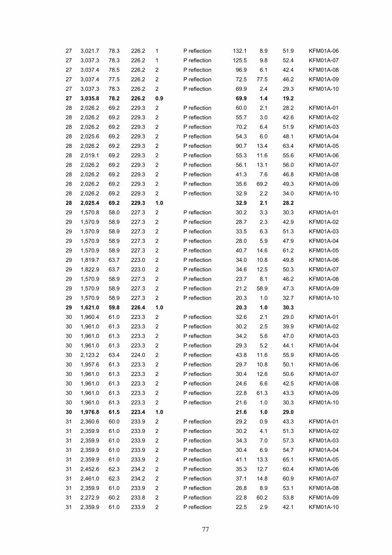
77
27 3,021.7 78.3 226.2 1 P reflection 132.1 8.9 51.9 KFM01A-06
27 3,037.3 78.3 226.2 1 P reflection 125.5 9.8 52.4 KFM01A-07
27 3,037.4 78.5 226.2 2 P reflection 96.9 6.1 42.4 KFM01A-08
27 3,037.4 77.5 226.2 2 P reflection 72.5 77.5 46.2 KFM01A-09
27 3,037.3 78.3 226.2 2 P reflection 69.9 2.4 29.3 KFM01A-10
27 3,035.8 78.2 226.2 0.9 69.9 1.4 19.228 2,026.2 69.2 229.3 2 P reflection 60.0 2.1 28.2 KFM01A-01
28 2,026.2 69.2 229.3 2 P reflection 55.7 3.0 42.6 KFM01A-02
28 2,026.2 69.2 229.3 2 P reflection 70.2 6.4 51.9 KFM01A-03
28 2,025.6 69.2 229.3 2 P reflection 54.3 6.0 48.1 KFM01A-04
28 2,026.2 69.2 229.3 2 P reflection 90.7 13.4 63.4 KFM01A-05
28 2,019.1 69.2 229.3 2 P reflection 55.3 11.6 55.6 KFM01A-06
28 2,026.2 69.2 229.3 2 P reflection 56.1 13.1 56.0 KFM01A-07
28 2,026.2 69.2 229.3 2 P reflection 41.3 7.6 46.8 KFM01A-08
28 2,026.2 69.2 229.3 2 P reflection 35.6 69.2 49.3 KFM01A-09
28 2,026.2 69.2 229.3 2 P reflection 32.9 2.2 34.0 KFM01A-10
28 2,025.4 69.2 229.3 1.0 32.9 2.1 28.229 1,570.8 58.0 227.3 2 P reflection 30.2 3.3 30.3 KFM01A-01
29 1,570.9 58.9 227.3 2 P reflection 28.7 2.3 42.9 KFM01A-02
29 1,570.9 58.9 227.3 2 P reflection 33.5 6.3 51.3 KFM01A-03
29 1,570.9 58.9 227.3 2 P reflection 28.0 5.9 47.9 KFM01A-04
29 1,570.9 58.9 227.3 2 P reflection 40.7 14.6 61.2 KFM01A-05
29 1,819.7 63.7 223.0 2 P reflection 34.0 10.8 49.8 KFM01A-06
29 1,822.9 63.7 223.0 2 P reflection 34.6 12.5 50.3 KFM01A-07
29 1,570.9 58.9 227.3 2 P reflection 23.7 8.1 46.2 KFM01A-08
29 1,570.9 58.9 227.3 2 P reflection 21.2 58.9 47.3 KFM01A-09
29 1,570.9 58.9 227.3 2 P reflection 20.3 1.0 32.7 KFM01A-10
29 1,621.0 59.8 226.4 1.0 20.3 1.0 30.330 1,960.4 61.0 223.3 2 P reflection 32.6 2.1 29.0 KFM01A-01
30 1,961.0 61.3 223.3 2 P reflection 30.2 2.5 39.9 KFM01A-02
30 1,961.0 61.3 223.3 2 P reflection 34.2 5.6 47.0 KFM01A-03
30 1,961.0 61.3 223.3 2 P reflection 29.3 5.2 44.1 KFM01A-04
30 2,123.2 63.4 224.0 2 P reflection 43.8 11.6 55.9 KFM01A-05
30 1,957.6 61.3 223.3 2 P reflection 29.7 10.8 50.1 KFM01A-06
30 1,961.0 61.3 223.3 2 P reflection 30.4 12.6 50.6 KFM01A-07
30 1,961.0 61.3 223.3 2 P reflection 24.6 6.6 42.5 KFM01A-08
30 1,961.0 61.3 223.3 2 P reflection 22.8 61.3 43.3 KFM01A-09
30 1,961.0 61.3 223.3 2 P reflection 21.6 1.0 30.3 KFM01A-10
30 1,976.8 61.5 223.4 1.0 21.6 1.0 29.031 2,360.6 60.0 233.9 2 P reflection 29.2 0.9 43.3 KFM01A-01
31 2,359.9 61.0 233.9 2 P reflection 30.2 4.1 51.3 KFM01A-02
31 2,359.9 61.0 233.9 2 P reflection 34.3 7.0 57.3 KFM01A-03
31 2,359.9 61.0 233.9 2 P reflection 30.4 6.9 54.7 KFM01A-04
31 2,359.9 61.0 233.9 2 P reflection 41.1 13.3 65.1 KFM01A-05
31 2,452.6 62.3 234.2 2 P reflection 35.3 12.7 60.4 KFM01A-06
31 2,461.0 62.3 234.2 2 P reflection 37.1 14.8 60.9 KFM01A-07
31 2,359.9 61.0 233.9 2 P reflection 26.8 8.9 53.1 KFM01A-08
31 2,272.9 60.2 233.8 2 P reflection 22.8 60.2 53.8 KFM01A-09
31 2,359.9 61.0 233.9 2 P reflection 22.5 2.9 42.1 KFM01A-10

78
31 2,370.6 61.1 234.0 1.0 22.5 0.9 42.132 2,953.1 63.2 215.9 2 P reflection 31.2 0.6 27.2 KFM01A-01
32 2,952.7 64.3 215.9 2 P reflection 30.7 2.3 34.1 KFM01A-02
32 2,952.7 64.3 215.9 2 P reflection 33.1 4.3 39.2 KFM01A-03
32 2,952.7 64.3 215.9 2 P reflection 29.7 3.9 37.1 KFM01A-04
32 2,952.7 64.3 215.9 2 P reflection 35.3 8.0 45.6 KFM01A-05
32 2,950.4 64.0 215.9 2 P reflection 28.3 7.3 41.9 KFM01A-06
32 2,953.1 64.0 215.9 2 P reflection 28.4 8.6 42.6 KFM01A-07
32 2,952.7 64.3 215.9 2 P reflection 25.5 4.6 35.7 KFM01A-08
32 2,952.7 64.3 215.9 2 P reflection 24.6 64.3 35.9 KFM01A-09
32 2,952.7 64.3 215.9 2 P reflection 23.2 0.7 25.7 KFM01A-10
32 2,952.6 64.1 215.9 1.0 23.2 0.6 25.733 153.3 33.9 203.6 2 P reflection 18.0 10.8 49.1 KFM01A-03
33 153.3 33.9 203.6 2 P reflection 12.4 9.4 14.9 KFM01A-04
33 153.3 33.9 203.6 2 P reflection 32.7 29.6 55.7 KFM01A-05
33 153.3 33.9 203.6 2 P reflection 21.1 9.7 45.6 KFM01A-06
33 153.3 33.9 203.6 2 P reflection 22.6 11.3 45.0 KFM01A-07
33 153.3 33.9 180.0 1 P reflection 16.8 7.2 4.3 KFM01A-08
33 153.3 33.9 199.6 0.6 12.4 7.2 4.334 –35.8 32.3 193.6 2 PS conversion 78.4 11.3 156.6 KFM01A-06
34 –35.8 32.3 193.6 2 PS conversion 29.0 12.0 170.6 KFM01A-08
34 –35.8 32.3 193.6 2 PS conversion 1.6 32.3 13.6 KFM01A-09
34 –35.8 32.3 193.6 2 PS conversion 3.8 18.8 143.9 KFM01A-10
34 –35.8 32.3 193.6 0.4 1.6 11.3 13.635 –1.3 32.2 193.5 2 PS conversion 29.3 13.2 170.9 KFM01A-08
35 –1.3 32.2 193.5 1 PS conversion 5.2 32.2 13.5 KFM01A-09
35 –1.3 32.2 193.5 1 PS conversion 8.2 18.3 141.4 KFM01A-10
35 –1.3 32.2 193.5 0.2 5.2 13.2 13.543 168.9 22.0 152.0 2 P reflection 12.7 2.8 37.0 KFM01A-04
43 168.9 22.0 152.0 2 P reflection 16.0 16.9 28.8 KFM01A-05
43 169.0 22.0 152.0 2 P reflection 19.0 21.1 6.0 KFM01A-06
43 168.9 22.0 152.0 2 P reflection 22.4 26.8 32.1 KFM01A-08
43 168.9 22.0 172.0 1 P reflection 33.1 22.0 8.0 KFM01A-09
43 168.9 22.0 156.0 0.5 12.7 2.8 6.045 311.3 35.0 175.0 2 P reflection 11.8 10.9 5.4 KFM01A-04
45 311.3 35.0 175.0 2 P reflection 15.3 13.7 28.8 KFM01A-05
45 311.5 35.0 175.0 2 P reflection 14.3 3.7 18.2 KFM01A-06
45 311.3 35.0 175.0 2 P reflection 14.5 2.2 7.8 KFM01A-08
45 311.3 35.0 175.0 2 P reflection 25.4 35.0 5.0 KFM01A-09
45 311.3 35.0 175.0 2 P reflection 23.2 20.3 32.5 KFM01A-10
45 311.3 35.0 175.0 0.6 11.8 2.2 5.046 2,226.6 58.7 234.1 1 P reflection 27.3 7.0 55.2 KFM01A-04
46 2,226.6 58.7 234.1 1 P reflection 36.5 13.7 65.5 KFM01A-05
46 2,220.1 58.7 234.1 1 P reflection 29.7 13.5 60.6 KFM01A-06
46 2,226.6 58.7 234.1 1 P reflection 24.5 9.2 53.5 KFM01A-08
46 2,226.6 58.7 234.1 1 P reflection 21.5 58.7 54.1 KFM01A-09
46 2,226.6 58.7 234.1 1 P reflection 20.7 2.7 42.3 KFM01A-10
46 2,225.5 58.7 234.1 0.3 20.7 2.7 42.349 913.2 61.7 206.9 1 P reflection 30.3 2.4 26.0 KFM01A-04

79
49 913.2 60.0 206.9 1 P reflection 20.4 1.5 7.6 KFM01A-10
49 913.2 60.8 206.9 0.1 20.4 1.5 7.6
Table B-2. Geometrical parameters of reflectors interpreted from VSP data acquired in borehole KFM02A. The lines written in bold fonts give the mean values for each parameter, as computed for each reflector.
No Borehole length (m)
Dip (°) Dip dir (°)
Visibility marks
Event type Delta depth (m)
Delta Dip (°)
Delta Dip dir (°)
Shot point
1 1,530.9 32.3 95.1 2 P reflection 11.9 4.5 75.8 KFM02A-01
1 1,537.2 31.4 95.0 2 P reflection 11.3 11.6 55.4 KFM02A-02
1 1,530.9 32.3 95.1 2 P reflection 12.7 16.1 54.9 KFM02A-03
1 1,530.9 32.3 95.1 2 P reflection 15.4 14.5 89.1 KFM02A-04
1 1,455.3 26.9 100.2 2 P reflection 14.6 19.3 89.6 KFM02A-06
1 1,530.9 32.3 115.1 2 P reflection 12.5 5.7 64.7 KFM02A-07
1 1,530.9 32.3 105.1 2 P reflection 11.4 4.3 59.1 KFM02A-08
1 1,530.9 32.3 95.1 2 P reflection 12.4 5.4 75.6 KFM02A-09
1 1,530.9 32.3 95.1 2 P reflection 12.1 4.3 67.7 KFM02A-10
1 1,523.2 31.6 99.0 0.9 11.3 4.3 54.92 1,302.8 42.0 127.8 2 P reflection 14.0 4.5 46.3 KFM02A-01
2 1,248.7 40.7 127.0 2 P reflection 13.9 8.4 31.9 KFM02A-02
2 1,302.8 42.0 127.8 2 P reflection 19.6 10.3 34.0 KFM02A-03
2 1,302.8 42.0 127.8 2 P reflection 17.4 11.8 63.1 KFM02A-06
2 1,302.8 42.0 127.8 2 P reflection 14.3 4.1 53.7 KFM02A-07
2 1,302.8 42.0 127.8 2 P reflection 12.9 4.8 39.7 KFM02A-08
2 1,302.8 42.0 127.8 2 P reflection 12.9 1.1 43.5 KFM02A-09
2 1,302.8 42.0 147.8 2 P reflection 12.3 4.4 14.4 KFM02A-10
2 1,296.1 41.9 130.2 0.8 12.3 1.1 14.43 2,222.2 40.2 158.7 2 P reflection 13.2 3.6 14.8 KFM02A-01
3 2,117.4 35.2 157.8 2 P reflection 12.8 3.7 6.1 KFM02A-02
3 2,117.4 35.2 157.8 2 P reflection 15.0 3.7 8.4 KFM02A-03
3 1,981.5 29.9 156.3 2 P reflection 16.0 3.6 25.2 KFM02A-04
3 2,117.4 35.2 157.8 2 P reflection 12.1 0.7 28.2 KFM02A-06
3 2,117.4 35.2 157.8 2 P reflection 11.7 3.3 19.5 KFM02A-07
3 2,117.4 35.2 157.8 2 P reflection 11.8 4.1 9.5 KFM02A-08
3 2,117.4 35.2 157.8 2 P reflection 11.5 4.3 11.2 KFM02A-09
3 2,117.4 35.2 157.8 2 P reflection 11.4 4.4 4.4 KFM02A-10
3 2,114.0 35.1 157.7 0.9 11.4 0.7 4.44 1,389.7 57.0 183.2 1 P reflection 23.9 1.1 6.0 KFM02A-01
4 1,389.7 54.0 180.0 1 P reflection 27.4 1.3 15.6 KFM02A-02
4 1,389.7 55.0 180.0 1 P reflection 17.4 1.1 10.4 KFM02A-06
4 1,389.7 55.0 180.0 1 P reflection 16.9 1.7 2.0 KFM02A-07
4 1,389.7 54.0 180.0 1 P reflection 18.8 0.4 8.7 KFM02A-08
4 1,389.7 55.0 180.0 1 P reflection 17.0 0.8 6.1 KFM02A-09
4 1,389.7 56.0 185.0 2 P reflection 18.4 1.9 16.8 KFM02A-10
4 1,389.7 55.1 181.2 0.4 16.9 0.4 2.05 1,170.7 40.6 177.8 1 P reflection 14.6 1.7 3.3 KFM02A-01
5 1,098.7 35.0 175.3 2 P reflection 15.7 1.6 16.6 KFM02A-02
5 1,170.7 40.6 177.8 2 P reflection 33.2 1.1 16.9 KFM02A-03

80
5 1,170.7 38.0 167.8 1 PSconversion 38.1 27.5 23.9 KFM02A-04
5 1,170.7 40.6 177.8 2 P reflection 12.6 2.5 3.5 KFM02A-07
5 1,170.7 40.6 177.8 2 P reflection 13.6 0.5 10.0 KFM02A-08
5 1,170.7 40.6 177.8 2 P reflection 12.6 1.4 7.2 KFM02A-09
5 1,170.7 40.6 177.8 1 P reflection 13.0 1.2 14.6 KFM02A-10
5 1,161.7 39.6 176.2 0.65 12.6 0.5 3.36 1,745.4 40.0 159.4 2 P reflection 13.4 3.4 14.2 KFM02A-01
6 1,714.0 38.6 159.0 2 P reflection 14.0 3.2 4.8 KFM02A-02
6 1,714.0 38.6 159.0 2 P reflection 18.2 3.4 6.9 KFM02A-03
6 1,714.1 38.0 159.0 2 P reflection 23.8 3.1 28.3 KFM02A-04
6 1,714.0 38.6 159.0 2 P reflection 13.0 0.6 29.2 KFM02A-06
6 1,714.1 36.0 159.0 2 P reflection 11.8 2.8 19.7 KFM02A-07
6 1,714.0 38.6 159.0 2 P reflection 12.4 3.6 9.0 KFM02A-08
6 1,714.0 38.6 159.0 2 P reflection 12.0 3.8 11.1 KFM02A-09
6 1,714.0 38.6 159.0 2 P reflection 11.9 3.8 3.9 KFM02A-10
6 1,717.5 38.4 159.0 0.9 11.8 0.6 3.97 1,737.7 42.8 163.1 1 P reflection 14.2 3.0 11.2 KFM02A-01
7 1,737.7 42.8 163.1 2 P reflection 15.4 2.5 2.3 KFM02A-02
7 1,737.7 42.8 163.1 2 P reflection 21.2 2.8 3.9 KFM02A-03
7 1,737.7 40.0 163.1 1 P reflection 26.0 2.8 24.9 KFM02A-04
7 1,737.7 42.8 163.1 2 P reflection 13.7 0.1 24.9 KFM02A-06
7 1,737.7 42.8 163.1 2 P reflection 13.0 2.4 16.4 KFM02A-07
7 1,731.8 42.2 163.0 1 P reflection 13.2 3.0 6.3 KFM02A-08
7 1,737.7 42.8 163.1 2 P reflection 12.7 3.2 8.4 KFM02A-09
7 1,737.7 42.8 163.1 2 P reflection 12.7 2.9 2.0 KFM02A-10
7 1,737.0 42.4 163.1 0.75 12.7 0.1 2.08 1,237.5 31.6 133.4 2 P reflection 11.9 4.8 37.3 KFM02A-01
8 1,237.5 31.6 133.4 2 P reflection 12.2 6.9 19.7 KFM02A-02
8 1,237.5 31.6 133.4 2 P reflection 16.1 7.7 23.4 KFM02A-03
8 1,237.5 30.0 143.4 1 P reflection 23.7 3.9 49.5 KFM02A-04
8 1,237.5 31.6 133.4 2 P reflection 14.2 12.4 57.9 KFM02A-06
8 1,237.5 31.6 133.4 1 P reflection 12.2 3.6 47.2 KFM02A-07
8 1,237.5 30.0 143.4 2 P reflection 11.1 5.5 16.9 KFM02A-08
8 1,237.5 31.6 133.4 2 P reflection 11.4 2.6 33.5 KFM02A-09
8 1,237.5 32.0 123.4 1 P reflection 11.5 3.2 32.2 KFM02A-10
8 1,237.5 31.3 134.6 0.75 11.1 2.6 16.99 1,430.7 33.3 123.4 2 P reflection 12.0 5.1 47.8 KFM02A-01
9 1,430.7 33.3 123.4 2 P reflection 12.0 8.7 31.7 KFM02A-02
9 1,430.7 33.3 123.4 2 P reflection 14.7 10.2 34.6 KFM02A-03
9 1,430.7 33.3 123.4 2 P reflection 19.9 8.0 64.7 KFM02A-04
9 1,430.7 33.3 123.4 2 P reflection 14.5 12.5 66.5 KFM02A-06
9 1,430.7 33.3 123.4 2 P reflection 12.5 4.5 56.7 KFM02A-07
9 1,430.7 33.3 123.4 2 P reflection 11.4 5.4 40.3 KFM02A-08
9 1,430.7 33.3 123.4 2 P reflection 11.6 1.1 45.3 KFM02A-09
9 1,430.7 33.3 123.4 2 P reflection 11.4 3.7 34.5 KFM02A-10
9 1,430.7 33.3 123.4 0.9 11.4 1.1 31.710 1,549.2 18.1 115.6 2 P reflection 10.4 9.9 29.1 KFM02A-01
10 1,549.2 20.0 145.6 1 P reflection 10.9 4.6 4.6 KFM02A-02
10 1,549.2 18.1 115.6 2 P reflection 11.6 8.5 9.9 KFM02A-03
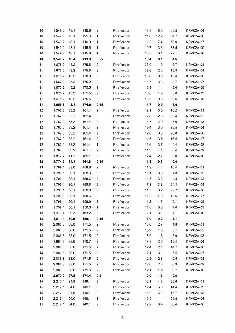
81
10 1,549.2 18.1 115.6 2 P reflection 13.3 8.6 65.5 KFM02A-04
10 1,549.3 18.1 125.6 1 P reflection 11.8 12.2 64.7 KFM02A-06
10 1,549.2 18.1 110.0 1 P reflection 11.2 7.4 68.0 KFM02A-07
10 1,549.2 18.1 115.6 1 P reflection 10.7 3.6 37.5 KFM02A-09
10 1,549.2 18.1 115.6 1 P reflection 10.8 0.1 27.1 KFM02A-10
10 1,549.2 18.4 119.9 0.55 10.4 0.1 4.611 1,675.2 43.2 175.5 2 P reflection 23.9 1.0 8.7 KFM02A-03
11 1,675.2 43.2 175.5 2 P reflection 33.6 2.2 15.8 KFM02A-04
11 1,675.2 43.2 170.0 2 P reflection 13.6 0.9 18.4 KFM02A-06
11 1,567.2 35.2 175.2 2 P reflection 11.7 3.3 3.7 KFM02A-07
11 1,675.2 43.2 175.5 1 P reflection 13.9 1.4 5.6 KFM02A-08
11 1,675.2 43.2 175.5 2 P reflection 13.0 1.9 3.6 KFM02A-09
11 1,675.2 43.2 175.5 2 P reflection 13.2 0.5 9.6 KFM02A-10
11 1,659.8 42.1 174.6 0.65 11.7 0.5 3.612 1,762.0 33.2 161.4 2 P reflection 12.1 3.6 10.2 KFM02A-01
12 1,762.0 33.2 161.4 2 P reflection 12.8 2.8 0.4 KFM02A-02
12 1,762.0 33.2 161.4 2 P reflection 15.7 2.9 3.0 KFM02A-03
12 1,762.0 33.2 161.4 2 P reflection 19.4 3.0 23.5 KFM02A-04
12 1,762.0 33.2 161.4 2 P reflection 12.0 0.3 26.8 KFM02A-06
12 1,762.0 33.2 161.4 2 P reflection 11.5 3.5 16.5 KFM02A-07
12 1,762.0 33.2 161.4 1 P reflection 11.6 3.7 4.4 KFM02A-08
12 1,762.0 33.2 161.4 2 P reflection 11.3 4.4 6.4 KFM02A-09
12 1,872.2 41.3 165.1 2 P reflection 12.4 2.7 0.0 KFM02A-10
12 1,774.3 34.1 161.8 0.85 11.3 0.3 0.013 1,799.1 28.0 158.6 2 P reflection 11.3 4.4 10.4 KFM02A-01
13 1,799.1 30.1 158.6 2 P reflection 12.1 3.3 1.3 KFM02A-02
13 1,799.1 30.1 158.6 2 P reflection 14.5 3.3 4.3 KFM02A-03
13 1,799.1 30.1 158.6 2 P reflection 17.3 3.3 24.8 KFM02A-04
13 1,799.1 30.1 158.6 2 P reflection 11.7 0.2 29.7 KFM02A-06
13 1,799.1 30.1 158.6 2 P reflection 11.2 4.0 18.6 KFM02A-07
13 1,799.1 30.1 158.6 2 P reflection 11.2 4.3 5.1 KFM02A-08
13 1,799.1 30.1 158.6 1 P reflection 11.0 5.3 7.0 KFM02A-09
13 1,910.4 39.3 163.2 2 P reflection 12.1 3.1 1.1 KFM02A-10
13 1,811.4 30.9 159.1 0.85 11.0 0.2 1.114 2,086.8 38.0 171.5 2 P reflection 13.0 2.7 1.8 KFM02A-01
14 2,086.8 38.0 171.5 2 P reflection 13.9 1.6 5.7 KFM02A-02
14 2,086.8 38.0 171.5 2 P reflection 16.9 1.8 3.9 KFM02A-03
14 1,961.9 33.6 170.7 2 P reflection 18.3 2.6 12.4 KFM02A-04
14 2,086.8 38.0 171.5 2 P reflection 12.4 2.1 14.7 KFM02A-06
14 2,086.8 38.0 171.5 2 P reflection 12.1 3.1 6.5 KFM02A-07
14 2,086.8 38.0 171.5 2 P reflection 12.5 2.3 2.5 KFM02A-08
14 2,086.8 38.0 171.5 2 P reflection 12.0 2.8 0.9 KFM02A-09
14 2,086.8 38.0 171.5 2 P reflection 12.1 1.9 6.7 KFM02A-10
14 2,073.0 37.5 171.4 0.9 12.0 1.6 0.915 2,217.1 34.8 149.1 2 P reflection 12.1 4.6 22.6 KFM02A-01
15 2,217.1 34.8 149.1 2 P reflection 12.4 5.0 14.4 KFM02A-02
15 2,217.1 34.8 149.1 2 P reflection 14.2 5.1 16.7 KFM02A-03
15 2,217.1 34.0 149.1 2 P reflection 16.3 4.4 31.8 KFM02A-04
15 2,217.1 34.8 149.1 2 P reflection 12.2 0.4 36.4 KFM02A-06

82
15 2,217.1 34.8 149.1 2 P reflection 11.7 2.9 28.0 KFM02A-07
15 2,158.8 31.2 148.3 2 P reflection 11.2 5.4 16.4 KFM02A-08
15 2,217.1 34.8 149.1 2 P reflection 11.4 4.7 19.7 KFM02A-09
15 2,217.1 34.8 149.1 2 P reflection 11.3 5.4 12.5 KFM02A-10
15 2,210.6 34.3 149.0 0.9 11.2 0.4 12.518 2,489.7 35.3 159.9 2 P reflection 12.2 3.9 12.1 KFM02A-01
18 2,489.7 35.3 159.9 2 P reflection 12.6 3.6 5.3 KFM02A-02
18 2,489.7 35.3 159.9 2 P reflection 14.3 3.6 7.4 KFM02A-03
18 2,489.7 35.3 159.9 2 P reflection 16.2 3.5 20.3 KFM02A-04
18 2,489.7 35.3 159.9 2 P reflection 11.8 4.0 8.1 KFM02A-08
18 2,489.7 35.3 159.9 0.5 11.8 3.5 5.324 –16,389.5 84.0 237.8 1 P reflection 600.4 2.4 123.0 KFM02A-01
24 –15,532.2 83.8 237.9 1 P reflection 296.1 0.9 115.3 KFM02A-02
24 –10,044.0 82.2 237.7 2 P reflection 40.6 1.0 117.9 KFM02A-03
24 –151,704.6 86.9 235.8 2 P reflection 23,387.8 2.6 46.1 KFM02A-04
24 –10,044.0 82.2 237.7 1 P reflection 5,349.9 7.8 38.2 KFM02A-06
24 –11,477.0 82.8 237.2 2 P reflection 878.2 4.9 129.6 KFM02A-07
24 –47,474.4 86.0 237.9 1 P reflection 5,992.2 1.8 118.1 KFM02A-08
24 84.0 237.4 0.5 40.6 0.9 38.226 –73.0 65.0 220.0 1 P reflection 22.1 24.5 71.8 KFM02A-02
26 –73.0 65.0 220.0 1 P reflection 28.3 50.7 17.3 KFM02A-03
26 –73.0 65.0 220.0 1 PSconversion 19.0 19.6 58.4 KFM02A-04
26 65.0 220.0 0.15 19.0 19.6 17.327 –12,550.0 86.7 228.1 1 P reflection 6,163.4 2.6 133.7 KFM02A-01
27 11,152.3 89.4 228.4 1 P reflection 4,366.4 0.5 67.6 KFM02A-02
27 –12,550.0 86.7 228.1 1 P reflection 1,411.0 0.6 116.9 KFM02A-03
27 11,152.3 89.4 228.4 1 P reflection 2,234.4 10.1 19.0 KFM02A-04
27 4,935.1 89.1 49.1 1 P reflection 5,104.4 0.6 120.4 KFM02A-08
27 88.2 192.4 0.25 1,411.0 0.5 19.028 –404.2 69.2 229.3 1 P reflection 34.5 9.1 135.6 KFM02A-01
28 –404.2 69.2 229.3 1 P reflection 16.2 17.4 95.7 KFM02A-02
28 –404.2 69.2 229.3 1 P reflection 29.5 45.5 96.1 KFM02A-03
28 –404.2 67.0 229.3 1 PSconversion 119.2 45.9 105.0 KFM02A-04
28 –404.2 69.2 229.3 2 P reflection 2.8 13.6 117.5 KFM02A-08
28 68.8 229.3 0.3 2.8 9.1 95.729 227.9 58.9 227.3 2 P reflection 39.3 3.7 46.5 KFM02A-01
29 227.9 58.9 227.3 1 P reflection 44.6 5.2 28.3 KFM02A-02
29 227.9 58.9 227.3 1 P reflection 42.8 27.6 17.4 KFM02A-03
29 227.9 58.0 230.0 1 PSconversion 45.1 43.1 72.1 KFM02A-04
29 227.9 60.0 230.0 2 P reflection 22.8 5.9 28.2 KFM02A-06
29 227.9 58.9 227.3 2 P reflection 23.6 0.9 39.2 KFM02A-07
29 227.9 58.9 227.3 2 PSconversion 23.0 0.9 64.8 KFM02A-08
29 227.9 58.0 226.0 2 PSconversion 17.5 10.1 56.4 KFM02A-09
29 227.9 58.9 227.3 2 PSconversion 22.4 1.1 65.5 KFM02A-10
29 227.9 58.8 227.8 0.75 17.5 0.9 17.430 726.6 59.0 217.2 2 P reflection 39.3 2.5 38.7 KFM02A-01
30 726.6 59.0 217.2 1 P reflection 225.2 21.0 81.4 KFM02A-02
30 726.6 59.0 217.2 1 P reflection 20.4 0.7 22.2 KFM02A-06
30 726.6 59.0 217.2 1 P reflection 22.3 2.7 32.2 KFM02A-07
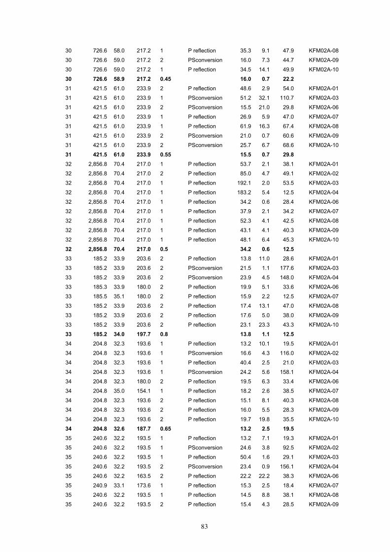
83
30 726.6 58.0 217.2 1 P reflection 35.3 9.1 47.9 KFM02A-08
30 726.6 59.0 217.2 2 PSconversion 16.0 7.3 44.7 KFM02A-09
30 726.6 59.0 217.2 1 P reflection 34.5 14.1 49.9 KFM02A-10
30 726.6 58.9 217.2 0.45 16.0 0.7 22.231 421.5 61.0 233.9 2 P reflection 48.6 2.9 54.0 KFM02A-01
31 421.5 61.0 233.9 1 PSconversion 51.2 32.1 110.7 KFM02A-03
31 421.5 61.0 233.9 2 PSconversion 15.5 21.0 29.8 KFM02A-06
31 421.5 61.0 233.9 1 P reflection 26.9 5.9 47.0 KFM02A-07
31 421.5 61.0 233.9 1 P reflection 61.9 16.3 67.4 KFM02A-08
31 421.5 61.0 233.9 2 PSconversion 21.0 0.7 60.6 KFM02A-09
31 421.5 61.0 233.9 2 PSconversion 25.7 6.7 68.6 KFM02A-10
31 421.5 61.0 233.9 0.55 15.5 0.7 29.832 2,856.8 70.4 217.0 1 P reflection 53.7 2.1 38.1 KFM02A-01
32 2,856.8 70.4 217.0 2 P reflection 85.0 4.7 49.1 KFM02A-02
32 2,856.8 70.4 217.0 1 P reflection 192.1 2.0 53.5 KFM02A-03
32 2,856.8 70.4 217.0 1 P reflection 183.2 5.4 12.5 KFM02A-04
32 2,856.8 70.4 217.0 1 P reflection 34.2 0.6 28.4 KFM02A-06
32 2,856.8 70.4 217.0 1 P reflection 37.9 2.1 34.2 KFM02A-07
32 2,856.8 70.4 217.0 1 P reflection 52.3 4.1 42.5 KFM02A-08
32 2,856.8 70.4 217.0 1 P reflection 43.1 4.1 40.3 KFM02A-09
32 2,856.8 70.4 217.0 1 P reflection 48.1 6.4 45.3 KFM02A-10
32 2,856.8 70.4 217.0 0.5 34.2 0.6 12.533 185.2 33.9 203.6 2 P reflection 13.8 11.0 28.6 KFM02A-01
33 185.2 33.9 203.6 2 PSconversion 21.5 1.1 177.6 KFM02A-03
33 185.2 33.9 203.6 2 PSconversion 23.9 4.5 148.0 KFM02A-04
33 185.3 33.9 180.0 2 P reflection 19.9 5.1 33.6 KFM02A-06
33 185.5 35.1 180.0 2 P reflection 15.9 2.2 12.5 KFM02A-07
33 185.2 33.9 203.6 2 P reflection 17.4 13.1 47.0 KFM02A-08
33 185.2 33.9 203.6 2 P reflection 17.6 5.0 38.0 KFM02A-09
33 185.2 33.9 203.6 2 P reflection 23.1 23.3 43.3 KFM02A-10
33 185.2 34.0 197.7 0.8 13.8 1.1 12.534 204.8 32.3 193.6 1 P reflection 13.2 10.1 19.5 KFM02A-01
34 204.8 32.3 193.6 1 PSconversion 16.6 4.3 116.0 KFM02A-02
34 204.8 32.3 193.6 1 P reflection 40.4 2.5 21.0 KFM02A-03
34 204.8 32.3 193.6 1 PSconversion 24.2 5.6 158.1 KFM02A-04
34 204.8 32.3 180.0 2 P reflection 19.5 6.3 33.4 KFM02A-06
34 204.8 35.0 154.1 1 P reflection 18.2 2.6 38.5 KFM02A-07
34 204.8 32.3 193.6 2 P reflection 15.1 8.1 40.3 KFM02A-08
34 204.8 32.3 193.6 2 P reflection 16.0 5.5 28.3 KFM02A-09
34 204.8 32.3 193.6 2 P reflection 19.7 19.8 35.5 KFM02A-10
34 204.8 32.6 187.7 0.65 13.2 2.5 19.535 240.6 32.2 193.5 1 P reflection 13.2 7.1 19.3 KFM02A-01
35 240.6 32.2 193.5 1 PSconversion 24.6 3.8 92.5 KFM02A-02
35 240.6 32.2 193.5 1 P reflection 50.4 1.6 29.1 KFM02A-03
35 240.6 32.2 193.5 2 PSconversion 23.4 0.9 156.1 KFM02A-04
35 240.6 32.2 163.5 2 P reflection 22.2 22.2 38.3 KFM02A-06
35 240.9 33.1 173.6 1 P reflection 15.3 2.5 18.4 KFM02A-07
35 240.6 32.2 193.5 1 P reflection 14.5 8.8 38.1 KFM02A-08
35 240.6 32.2 193.5 2 P reflection 15.4 4.3 28.5 KFM02A-09

84
35 240.6 32.2 193.5 2 P reflection 18.9 20.9 34.3 KFM02A-10
35 240.6 32.3 188.0 0.65 13.2 0.9 18.436 275.9 32.9 184.6 2 P reflection 13.3 6.1 10.4 KFM02A-01
36 275.9 32.0 184.6 2 P reflection 49.6 27.0 57.4 KFM02A-02
36 275.9 32.9 184.6 1 P reflection 61.2 3.3 45.8 KFM02A-03
36 275.9 32.9 184.6 2 PSconversion 23.8 9.4 159.9 KFM02A-04
36 275.9 32.9 154.6 2 P reflection 24.0 26.5 45.4 KFM02A-06
36 275.5 32.0 154.6 1 P reflection 16.4 11.2 34.7 KFM02A-07
36 275.9 32.9 184.6 1 P reflection 13.4 3.6 30.9 KFM02A-08
36 275.9 32.9 180.0 1 P reflection 14.0 1.9 15.4 KFM02A-09
36 275.9 32.9 190.0 2 P reflection 17.5 18.0 31.4 KFM02A-10
36 275.8 32.7 178.0 0.7 13.3 1.9 10.437 340.4 50.8 173.7 2 P reflection 21.7 4.3 4.2 KFM02A-01
37 340.4 50.8 173.7 2 PSconversion 22.0 11.8 43.7 KFM02A-02
37 340.4 50.8 173.7 1 P reflection 40.8 10.3 26.4 KFM02A-03
37 340.4 48.0 173.7 1 PSconversion 31.5 36.0 116.7 KFM02A-04
37 340.4 50.8 173.7 2 P reflection 20.1 3.7 26.5 KFM02A-06
37 340.4 50.8 173.7 2 P reflection 16.2 4.1 14.1 KFM02A-07
37 340.4 50.8 173.7 2 P reflection 16.4 1.3 11.3 KFM02A-08
37 340.4 50.8 173.7 1 P reflection 15.2 5.4 4.0 KFM02A-09
37 340.4 50.8 173.7 2 P reflection 16.5 0.8 14.5 KFM02A-10
37 340.4 50.5 173.7 0.75 15.2 0.8 4.038 479.9 49.0 164.1 2 P reflection 20.0 3.5 12.8 KFM02A-01
38 452.3 46.8 163.9 1 P reflection 35.6 7.2 23.3 KFM02A-02
38 452.3 46.8 135.0 2 PSconversion 26.0 33.0 45.3 KFM02A-03
38 452.3 50.0 173.0 1 PSconversion 38.1 36.6 80.5 KFM02A-04
38 452.3 45.0 163.9 2 P reflection 19.2 9.7 34.6 KFM02A-06
38 452.3 46.8 163.9 2 P reflection 15.3 0.2 22.6 KFM02A-07
38 452.3 46.8 163.9 2 P reflection 14.5 2.9 1.2 KFM02A-08
38 452.3 48.0 163.9 1 P reflection 14.1 4.7 5.7 KFM02A-09
38 452.3 46.8 173.9 2 P reflection 15.2 0.9 14.5 KFM02A-10
38 455.4 47.3 162.8 0.75 14.1 0.2 1.239 529.7 24.9 148.9 2 P reflection 11.4 5.4 19.4 KFM02A-01
39 529.7 24.9 118.9 2 P reflection 12.4 5.2 4.2 KFM02A-02
39 529.7 22.0 128.9 1 P reflection 24.4 3.1 3.8 KFM02A-03
39 529.7 24.9 118.9 1 P reflection 69.6 4.5 117.9 KFM02A-04
39 529.6 24.9 158.9 1 P reflection 16.3 22.8 40.0 KFM02A-06
39 529.7 24.9 138.9 1 P reflection 14.2 17.9 46.9 KFM02A-07
39 526.7 35.0 130.0 2 P reflection 11.6 6.1 25.7 KFM02A-08
39 529.7 24.9 118.9 2 P reflection 13.4 15.7 50.1 KFM02A-09
39 529.7 22.0 168.9 2 P reflection 13.4 15.6 14.8 KFM02A-10
39 529.3 25.4 136.8 0.7 11.4 3.1 3.840 575.2 40.4 151.3 1 P reflection 15.2 3.8 23.5 KFM02A-01
40 575.2 40.4 151.3 1 P reflection 20.2 1.0 5.1 KFM02A-02
40 575.2 40.4 135.0 2 PSconversion 16.7 27.8 73.3 KFM02A-03
40 575.2 40.4 120.0 2 PSconversion 27.2 32.8 163.4 KFM02A-04
40 575.2 40.4 171.3 1 P reflection 15.8 6.2 27.2 KFM02A-06
40 575.2 40.4 151.3 2 P reflection 14.5 4.6 34.1 KFM02A-07
40 575.2 40.4 151.3 2 P reflection 12.7 4.3 10.2 KFM02A-08

85
40 575.2 40.4 151.3 2 P reflection 12.7 4.0 16.5 KFM02A-09
40 575.2 40.4 171.3 2 P reflection 13.6 0.9 13.8 KFM02A-10
40 575.2 40.4 150.5 0.75 12.7 0.9 5.141 631.1 39.4 156.3 2 P reflection 14.9 3.4 18.2 KFM02A-01
41 631.1 39.4 156.3 2 P reflection 19.9 0.5 7.6 KFM02A-02
41 631.1 39.4 136.3 2 PSconversion 14.2 26.9 78.9 KFM02A-03
41 631.1 39.4 126.3 2 PSconversion 18.0 33.1 176.7 KFM02A-04
41 631.1 39.4 166.3 2 P reflection 15.8 7.9 31.1 KFM02A-06
41 631.1 39.4 156.3 2 P reflection 13.7 2.3 28.6 KFM02A-07
41 631.1 39.4 156.3 1 P reflection 12.7 3.5 6.0 KFM02A-08
41 631.1 39.4 156.3 2 P reflection 12.4 4.3 11.3 KFM02A-09
41 631.1 39.4 176.3 2 P reflection 13.6 3.3 17.2 KFM02A-10
41 631.1 39.4 154.1 0.85 12.4 0.5 6.042 699.2 36.4 177.5 1 P reflection 14.4 1.7 3.4 KFM02A-01
42 699.2 36.4 177.5 2 P reflection 20.9 5.6 25.7 KFM02A-02
42 699.2 36.4 147.5 2 PSconversion 14.9 25.0 84.5 KFM02A-03
42 699.2 36.4 167.5 2 PSconversion 21.6 30.4 80.7 KFM02A-04
42 699.2 36.4 160.0 2 P reflection 15.6 10.6 36.5 KFM02A-06
42 699.2 36.4 157.5 2 P reflection 13.0 1.7 26.9 KFM02A-07
42 699.2 36.4 177.4 2 P reflection 13.0 0.7 13.9 KFM02A-08
42 699.2 37.0 177.5 1 P reflection 12.3 1.7 9.4 KFM02A-09
42 699.1 37.0 187.4 2 P reflection 14.1 8.5 26.3 KFM02A-10
42 699.2 36.6 170.0 0.8 12.3 0.7 3.443 789.1 25.0 162.0 2 P reflection 11.5 3.1 6.9 KFM02A-01
43 789.1 22.0 152.0 2 P reflection 12.6 0.8 11.8 KFM02A-02
43 789.1 20.0 132.0 2 P reflection 17.2 3.7 4.9 KFM02A-03
43 789.1 20.0 122.0 2 PSconversion 150.8 1.4 124.9 KFM02A-04
43 789.1 20.0 132.0 2 P reflection 15.7 27.9 63.3 KFM02A-06
43 830.0 18.4 121.3 2 P reflection 12.7 19.0 62.0 KFM02A-07
43 830.0 18.4 281.3 2 P reflection 13.9 22.0 115.4 KFM02A-08
43 830.0 18.4 281.3 2 P reflection 16.4 34.1 108.4 KFM02A-09
43 830.0 18.4 281.3 2 P reflection 21.5 44.2 114.6 KFM02A-10
43 807.3 20.0 185.0 0.9 11.5 0.8 4.944 916.8 45.0 165.6 1 P reflection 16.8 2.4 9.9 KFM02A-01
44 916.8 45.0 165.6 1 PSconversion 3.7 30.6 47.0 KFM02A-02
44 916.8 45.0 165.6 2 PSconversion 43.4 21.3 14.3 KFM02A-03
44 916.8 45.0 165.6 2 P reflection 15.8 3.8 28.3 KFM02A-06
44 916.8 44.0 165.6 2 P reflection 13.7 1.1 17.3 KFM02A-07
44 916.8 45.0 165.6 2 P reflection 14.6 2.0 1.9 KFM02A-08
44 916.8 45.0 165.6 2 P reflection 13.4 2.5 5.4 KFM02A-09
44 916.8 45.0 165.0 2 P reflection 13.5 1.6 2.8 KFM02A-10
44 916.8 44.9 165.5 0.7 3.7 1.1 1.945 982.4 35.0 175.0 2 P reflection 13.3 1.9 1.8 KFM02A-01
45 982.5 38.2 170.4 2 P reflection 17.4 1.2 12.6 KFM02A-02
45 982.5 38.2 170.4 2 PSconversion 15.4 25.7 41.3 KFM02A-03
45 982.5 39.0 170.0 1 PSconversion 53.1 25.3 28.3 KFM02A-04
45 982.5 38.2 170.4 1 P reflection 13.7 2.4 23.8 KFM02A-06
45 981.9 41.0 170.2 2 P reflection 12.9 1.9 12.1 KFM02A-07
45 982.5 38.2 170.4 2 P reflection 12.9 1.4 4.6 KFM02A-08
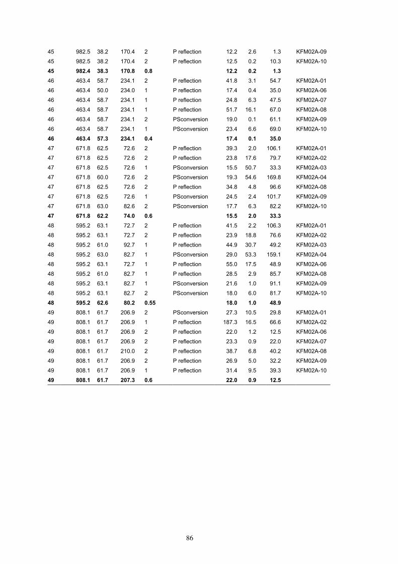
86
45 982.5 38.2 170.4 2 P reflection 12.2 2.6 1.3 KFM02A-09
45 982.5 38.2 170.4 2 P reflection 12.5 0.2 10.3 KFM02A-10
45 982.4 38.3 170.8 0.8 12.2 0.2 1.346 463.4 58.7 234.1 2 P reflection 41.8 3.1 54.7 KFM02A-01
46 463.4 50.0 234.0 1 P reflection 17.4 0.4 35.0 KFM02A-06
46 463.4 58.7 234.1 1 P reflection 24.8 6.3 47.5 KFM02A-07
46 463.4 58.7 234.1 1 P reflection 51.7 16.1 67.0 KFM02A-08
46 463.4 58.7 234.1 2 PSconversion 19.0 0.1 61.1 KFM02A-09
46 463.4 58.7 234.1 1 PSconversion 23.4 6.6 69.0 KFM02A-10
46 463.4 57.3 234.1 0.4 17.4 0.1 35.047 671.8 62.5 72.6 2 P reflection 39.3 2.0 106.1 KFM02A-01
47 671.8 62.5 72.6 2 P reflection 23.8 17.6 79.7 KFM02A-02
47 671.8 62.5 72.6 1 PSconversion 15.5 50.7 33.3 KFM02A-03
47 671.8 60.0 72.6 2 PSconversion 19.3 54.6 169.8 KFM02A-04
47 671.8 62.5 72.6 2 P reflection 34.8 4.8 96.6 KFM02A-08
47 671.8 62.5 72.6 1 PSconversion 24.5 2.4 101.7 KFM02A-09
47 671.8 63.0 82.6 2 PSconversion 17.7 6.3 82.2 KFM02A-10
47 671.8 62.2 74.0 0.6 15.5 2.0 33.348 595.2 63.1 72.7 2 P reflection 41.5 2.2 106.3 KFM02A-01
48 595.2 63.1 72.7 2 P reflection 23.9 18.8 76.6 KFM02A-02
48 595.2 61.0 92.7 1 P reflection 44.9 30.7 49.2 KFM02A-03
48 595.2 63.0 82.7 1 PSconversion 29.0 53.3 159.1 KFM02A-04
48 595.2 63.1 72.7 1 P reflection 55.0 17.5 48.9 KFM02A-06
48 595.2 61.0 82.7 1 P reflection 28.5 2.9 85.7 KFM02A-08
48 595.2 63.1 82.7 1 PSconversion 21.6 1.0 91.1 KFM02A-09
48 595.2 63.1 82.7 2 PSconversion 18.0 6.0 81.7 KFM02A-10
48 595.2 62.6 80.2 0.55 18.0 1.0 48.949 808.1 61.7 206.9 2 PSconversion 27.3 10.5 29.8 KFM02A-01
49 808.1 61.7 206.9 1 P reflection 187.3 16.5 66.6 KFM02A-02
49 808.1 61.7 206.9 2 P reflection 22.0 1.2 12.5 KFM02A-06
49 808.1 61.7 206.9 2 P reflection 23.3 0.9 22.0 KFM02A-07
49 808.1 61.7 210.0 2 P reflection 38.7 6.8 40.2 KFM02A-08
49 808.1 61.7 206.9 2 P reflection 26.9 5.0 32.2 KFM02A-09
49 808.1 61.7 206.9 1 P reflection 31.4 9.5 39.3 KFM02A-10
49 808.1 61.7 207.3 0.6 22.0 0.9 12.5