Embed Size (px)
Citation preview
FH2017-Rev B CoverPage Page 1 of 21
Team # School:
Date Started: Vehicle Name:
Time Started: Team Leader(s):
Faculty Advisor(s):
Rules and Safety Officer (RSO) RSO Name:
Cell Phone Number:
Backup RSO:
Backup RSO Cell Phone Number:
Date and Time Signoff By Inspector
Preliminary:
Full Electrical (Documentation):
Full Electrical (Inspection):
Full Electrical (Pouch Cells):
Full Electrical (Demonstration):
Accum. Energy & Fuel Allocation:
Safety & Charging (EV8 - Team Garage):
Rain Test:
Approved to Compete (Chief Inspector):
Notes
Formula-Hybrid 2017 Electrical Inspection
before mechanical inspection or performing any work on the vehicle.
Note: Preliminary Electrical Inspection must be completed

FH2017-Rev B Accumulator Data Page 2 of 21
Manufacturer: Part/Model number:
Datasheet Value _________V. At 2C rate: V@80%soc= ________V V@20%soc=________V Average =_________ V
Nominal Cell AH AH at 2C Rate ____________AH (2C = 2 x cell rated AH in Amps, or the current for a discharge time of 0.5h)
Nominal Cell Capacity _______________Wh using [ ] Datasheet or [ ] Average V
Configuration P/S Code: In Series: In Parallel: Total Cells:
Total Capacity: __________Wh (NO 80% DERATE) FH Fuel Equivalency Capacity (Wh x 0.8):________________Wh (FH Rules Appendix A)
Battery chemistry: Does cell contain metallic Li? Yes[ ] No [ ]
Segment Energy Limit (EV3.3.3, Table 9): __________MJ __________Wh Number of Cells in Segment_______ (NO 80% DERATE)
Manufacturer: Part/Model number:
[Cell] / [Module] Capacity (F): Maximum Operating Voltage (V):
Configuration P/S Code: In Series: In Parallel: Total [Cells]/[Modules]:
Overall Capacity # Strings Farads per String: String Max Voltage (V)
FH Fuel Equiv. Rating Rated Capacity: ______________Wh See FH Rules Appendix A.
Segment Energy Limit (EV3.3.3, Table 9): __________MJ __________Wh Number of Cells in Segment_______
Notes/Actions
Accumulator Data
Capacity Per Unit
ACCUMULATOR DATA FOR BATTERIESChemistry:
Nominal Cell Voltage
ACCUMULATOR DATA FOR CAPACITORSChemistry:

FH2017-Rev B Preliminary Page 3 of 21
TypeFH Inspector
Initials
Pre 1 1.2.1 Maximum TSV operating voltage is 300V
Pre 21.2.14.1.1 GLV voltage is less than 30 Vdc or 25 Vac
Pre 3 7.1.3 TS shutdown circuit directly carries AIR coil current, including master, shutdown switches.
Pre 4
7.1.1The shutdown circuit consists of at least 2 master switches, 3 shut-down buttons, the brake-over-travel-switch, a N.O. relay controlled by the insulation monitoring device (IMD), a N.O. relay controlled by the accumulator management system (AMS), plus all required interlocks.
Pre 57.5.5
Big Red Buttons must open the safety loop when pushed and must not act through logic or a microcontroller. Normally-closed, push-pull or push-rotate are all acceptable BRBs.
Pre 6
7.5.47.6.4
Pressing any shutdown button must open the shutdown circuit, open the AIRs, kill the engine and fuel pumps. Side mounted red buttons must shut down ALL electrical systems (with the exception of the engine starter). Control, telemetry, and instrumentation MAY remain energized if the cockpit BRB is depressed. (Refer to Figure 34)
Pre 7
7.3.17.3.2
The GLVMS: (a) disables power to ALL electrical circuits, including the alternator, lights, fuel pump(s), ignition and electrical controls.(b) All GLV (i.e. battery, alternator) current must flow through this switch.
Pre 87.3.3
Vehicles with GLV charging systems such as alternators or DC/DC converters must use a multi-pole switch to isolate the charging source from the GLV (See Figure 35)
Pre 9
7.4.17.4.27.4.3
The TSMS:(a) must be the last switch in the safety loop carrying the holding current to the AIRs.(b) must be identified with a sticker of a red lightning bolt in a blue triangle (see Figure 34)
Pre 107.1.5
Electronic systems that contain internal energy storage (i.e. hold-up energy to allow an orderly shutdown of the system upon loss of the GLV) must be prevented from back-feeding power onto the GLV.
Pre 119.5.2
REMOVABLE ACCUMULATOR CONTAINERS ONLY: Accumulator Voltage indicator is directly controlled by HV, not software or the AIR control signal
Pre 12 9.1.1 The car is equipped with a TSEL which must be lit and clearly visible any time the AIR coils are energized
Pre 13
9.3.49.3.5
TSVP must be directly controlled by voltage being present at the output of the accumulator (no Software control is permitted). No TS voltage is present at the TSVP. If isolated DC/DC converter used, output of converter is ground referenced
Pre 1410.3.4 The ESF shows where the TSMPs are connected to the positive and negative motor controller or inverter supply lines.
Pre 1510.3.5
Each TSMP is protected with a 10kΩ current limiting resistor. Power rating must be 2*(Maximum_TSV^2/10k), but not less than 5W.
Pre 16Ensure Fuse Table is attached to the ESF. Complete review will happen during the documentation stage in full inspection
Verify the following information is contained within the vehicle's DOCUMENTATION/ESF[ESF paragraphs noted, as applicable]
Operating Voltage: [ESF Section 1]
Safety Circuit: [ESF Section 2.1]
Indicator Operation: [ESF Sections 3.1.9, 2.5, 2.6]
TSMPs: [ESF Section 2.7]
Preliminary Electrical Inspection (required prior to Mechanical Inspection)Complies
Ref SummaryLine Item

FH2017-Rev B Preliminary Page 4 of 21
TypeFH Inspector
Initials
Preliminary Electrical Inspection (required prior to Mechanical Inspection)Complies
Ref SummaryLine Item
Pre 17 4.1.2 GLV battery is securely attached to frame
Pre 18
4.1.44.1.5
One terminal of the GLV battery or other GLV power source must be connected to the chassis by a stranded ground wire or flexible strap, with a minimum size of 12 AWG or equivalent cross-section. This ground wire must run directly from the GLV battery to the nearest frame ground and be secured at both ends.
Pre 19 6.1.6 GLV System is properly fused within close proximity to power sources (i.e. battery, alternator, etc.).Pre 20 4.1.3 Non-grounded GLV battery terminal is insulated
Pre 21
8.1.1
Except for components of the GLV system, all metal parts accessible when the vehicle is configured for driving, maintenance, or charging have a resistance below 300 milliohm (measured at 1 amp) to the GLV system ground. This includes metal containers.
Accessible parts are defined as those that are exposed in the normal driving configuration or when the vehicle is partially disassembled for maintenance or charging.
Pre 22
8.1.2All accessible parts of the vehicle containing conductive material (including coated metal parts or carbon-fiber parts) which might contact a damaged wire or electrical part, have a resistance below 100 ohm to the GLV system ground. If no convenient conductive point is available for testing, then an area of coating may be removed to create one.
Pre 23 8.1.4 Conductors used for grounding shall be stranded and 16 AWG minimum.
Pre 24T4.5.15.2.3 There are no HV components or TS wiring in the driver's compartment (Whether contained within conduit or not)
Pre 253.1.3
All parts of the TS circuity are protected by electrically insulating material. When the TS enclosures are in place, no conductive part of the TS circuitry can be touched with a 6 x 100 mm probe.
Pre 2610.3.110.3.3
Two 4 mm, shrouded, banana-jack TSMPs are installed in an easily accessible well marked location. Access must not require the removal of body panels.
Pre 27 10.3.2 The TSMPs are protected by a non-conductive housing that can be opened without tools.Pre 28 10.3.6 A shrouded, 4mm, banana-jack GLV ground terminal is available near the TSMP.
Pre 29 2.3.2 Each accumulator container MUST be prominently labeled with "ACCUMULATOR - ALWAYS ENERGIZED"30 4.6.1 A High Voltage sticker is applied to every container if TS voltage is > 30 Vdc
Pre 319.1.19.1.4 The TSEL is mounted under the highest point of the main roll hoop and helmet must not contact the TSEL
Pre 32 9.1.7 There are no other lights mounted in proximity to the TSEL.
Pre 339.5.1
REMOVABLE ACCUMULATOR CONTAINERS ONLY: There is a prominent indicator for voltage > 30V (LED or analog) when AIRs are closed. Analog electronics must be used for this indicator (no software)
Pre 34 7.2.1 There is both a Grounded Low Voltage Master Switch (GLVMS) and a Tractive System Master Switch (TSMS).
Pre 357.2.2
The GLVMS and TSMS are located on the right side of the vehicle, in proximity to the Main Hoop, at the driver’s shoulder height and is easily actuated from outside the car.
Pre 36 7.2.4 The GLVMS and TSMS are direct acting, i.e. it cannot act through a relay or logic.Pre 37 7.2.3 Both master switches must be of the rotary type, with a red, removable key (See Figure 36)Pre 38 7.2.5 The master switches are not easily removable and not mounted onto removable body work, etc.Pre 39 7.2.6 The function of both switches is clearly marked with “GLV” and “TSV”.
Pre 40
7.5.17.5.2
One big red button is located on each side of the vehicle behind the driver’s compartment at approximately the level of the driver’s head. The minimum allowed diameter of the shutdown buttons on both sides of the car is 38 mm.
Pre 417.6.17.6.3
The cockpit-mounted master switch must be easily accessible by the driver in any steering wheel position. The minimum allowed diameter of the shutdown button in the cockpit is 24 mm.
Pre 42 7.5.6 Side Mounted are not easily removable and not mounted to removable body work, etc.
INSPECT the vehicle for the following:Ground Low Voltage:
TSMPs:
Tractive System Wiring:
Vehicle Grounding:
Indicators and Safety Labels:
Safety Components:

FH2017-Rev B Preliminary Page 5 of 21
TypeFH Inspector
Initials
Preliminary Electrical Inspection (required prior to Mechanical Inspection)Complies
Ref SummaryLine Item
Pre 43 5.1.1 Use TSMPs to check TS/GLV isolation (Resistance Check using DMM). Pre 44 A6.4.2 Team should demonstrate their jack stand procedure. (Quick jack is not allowed for powered testing)
Pre 45
A6.4.212.1.12.9.7 RSO should explain and team should demonstrate their Lock-Out/Tag Out procedure
Pre 469.2.1
With meter attached to TSMPs, team should energize car. There should be a second action to put the car into “Ready-To-Drive” mode (Full demonstration of this requirement will happen during Full Inspection)
Pre 479.2.29.2.4 “Ready-To-Drive” Sound occurs (Note, dBA level will be checked at Noise Test)
Pre 48
9.1
TSEL is activated when AIR coils are energized: -Brightness -Color (Amber) -Flash Rate (2-5 Hz) -Position (Roll Hoop)
4912.2.15
Check that he charging port is only energized when the tractive system is energized and the TSEL is flashing. There must be no voltage present on the charging port when the tractive system is de-energized.
Pre 50
9.3
TSVP light -Location (Near BRBs) -Color (Red) -TSVP is activated when accumulator voltage is greater than 32VDC or 1/3 max tractive system bus voltage (whichever is higher)
Pre 51 7.2.7 Ensure both master switches are parallel to the fore-aft axis of the vehicle
Pre 52
2.8.37.5.37.5.47.6.27.6.47.6.5
Check operation of Big Red Buttons (repeat for each button) - Voltage should be <30V in less than 5 seconds. Time Measured _______________ - Voltage meter or indicator on accumulator indicates HV until output is <30V -Cockpit button is resettable Note: Preliminary Inspection Demonstration may be repeated during Full Inspection if there is any question of safety circuit operation
The following is the Preliminary Demonstration. The team should be able to perform the following actions upon request. Ability to complete these actions constitute passing the applicable rules.
Notes/Actions

FH2017-Rev B Preliminary Page 6 of 21
TypeFH Inspector
Initials
Preliminary Electrical Inspection (required prior to Mechanical Inspection)Complies
Ref SummaryLine Item
A6.4.2 Jack Stand Procedure (Quick Jack is not permitted for powered testing)A6.4.212.1.12.9.7
RSO can explain and team should demonstrate their Lock-Out/Tag-Out Procedure. Removal of the HVD must be part of the LOTO procedure.
9.2.1The car must make a characteristic sound, for a minimum of 1 second and a maximum of 3 seconds, when it is ready to drive. The vehicle cannot make any other sound similar to the ready to drive sound
9.2.29.2.4 The sound emitting device must produce a tone between 1000-3500Hz at 80dB(A) at 2Ft,
9.1.5 The TSEL is clearly visible from all horizontal directions even in bright sunlight.9.1.29.1.3 The TSEL is amber and flashes continuously with a frequency of 2-5 Hz.
9.1.6The TSEL must be visible from a person standing up to 3m away from the TSAL itself. The person's minimum eye height is 1.6m.
12.2.15The charging port shall only be energized when the tractive system is energized and the TSEL is flashing. i.e. there must be no voltage present on the charging port when the tractive system is de-energized.
9.3.1Two TSVP lights are present. Each TSVP must be each side of the roll bar near the shutdown buttons and easily seen from the side of the vehicle
9.3.2 TSVP must be red and comply with DOT FMVSS 108 for trailer clearance lamps
9.3.3TSVP must be lit and visible any time the voltage outside of the accumulator container exceeds 32VDC or 1/3 maximum tractive bus voltage (whichever is higher)
7.2.7 The “ON” position of both master switches is parallel to the fore-aft axis of the vehicle7.5.37.5.4
Side mounted red buttons must shut down all electrical systems (except I.C. engine starter). Buttons must be push pull or push-rotate where pushing the button opens the shutdown circuit.
7.6.27.6.4
Cockpit mounted BRB must open the AIRs and shut down the IC Engine (Control, telemetry, and instrumentation MAY remain energized) . Button must be push pull where pushing the button opens the shutdown circuit.
If the shutdown circuit is opened/interrupted the tractive system must be shut down by opening all accumulator isolation relays. The voltage in the tractive system must drop to under 30 VDC or 25 VAC RMS in less than five seconds.
Voltage decay to under 30 VDC or 25 VAC in less than 5 seconds. Time measured________
5.1.1There is no connection between the frame or other conductive surface and the TS circuits. (Use TSMPs to check TS/GLV isolation)
7.6.5
The cockpit-mounted shutdown button must be driver resettable. If the driver disables the system by pressing the cockpit shutdown button, the driver must then be able to restore system. Restoring the system must include pulling the button back out, taking the "additional action" to re-activate motor control and make the vehicle ready to drive sound.
2.8.3
Safety Circuit:
Indicators:
Ready to Drive Sound
RSOThe following is for REFERENCE ONLY with regards to demonstration requirements.
FH2017-Rev B Documentation Page 7 of 21
TypeFH Inspector
Initials
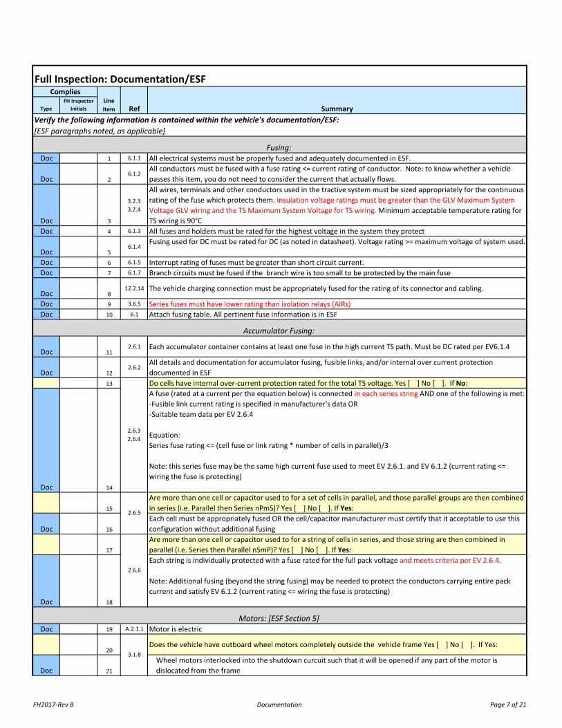
Doc 1 6.1.1 All electrical systems must be properly fused and adequately documented in ESF.
Doc 26.1.2
All conductors must be fused with a fuse rating <= current rating of conductor. Note: to know whether a vehicle passes this item, you do not need to consider the current that actually flows.
Doc 3
3.2.33.2.4
All wires, terminals and other conductors used in the tractive system must be sized appropriately for the continuous rating of the fuse which protects them. Insulation voltage ratings must be greater than the GLV Maximum System Voltage GLV wiring and the TS Maximum System Voltage for TS wiring. Minimum acceptable temperature rating for TS wiring is 90°C
Doc 4 6.1.3 All fuses and holders must be rated for the highest voltage in the system they protect
Doc 56.1.4
Fusing used for DC must be rated for DC (as noted in datasheet). Voltage rating >= maximum voltage of system used.
Doc 6 6.1.5 Interrupt rating of fuses must be greater than short circuit current. Doc 7 6.1.7 Branch circuits must be fused if the branch wire is too small to be protected by the main fuse
Doc 812.2.14 The vehicle charging connection must be appropriately fused for the rating of its connector and cabling.
Doc 9 3.6.5 Series fuses must have lower rating than isolation relays (AIRs)Doc 10 6.1 Attach fusing table. All pertinent fuse information is in ESF
Doc 112.6.1 Each accumulator container contains at least one fuse in the high current TS path. Must be DC rated per EV6.1.4
Doc 122.6.2
All details and documentation for accumulator fusing, fusible links, and/or internal over current protection documented in ESF
13 Do cells have internal over-current protection rated for the total TS voltage. Yes [ ] No [ ]. If No:
Doc 14
A fuse (rated at a current per the equation below) is connected in each series string AND one of the following is met:-Fusible link current rating is specified in manufacturer's data OR -Suitable team data per EV 2.6.4
Equation:Series fuse rating <= (cell fuse or link rating * number of cells in parallel)/3
Note: this series fuse may be the same high current fuse used to meet EV 2.6.1. and EV 6.1.2 (current rating <= wiring the fuse is protecting)
15
Are more than one cell or capacitor used to for a set of cells in parallel, and those parallel groups are then combined in series (i.e. Parallel then Series nPmS)? Yes [ ] No [ ]. If Yes:
Doc 16
Each cell must be appropriately fused OR the cell/capacitor manufacturer must certify that it acceptable to use this configuration without additional fusing
17
Are more than one cell or capacitor used to for a string of cells in series, and those string are then combined in parallel (i.e. Series then Parallel nSmP)? Yes [ ] No [ ]. If Yes:
Doc 18
Each string is individually protected with a fuse rated for the full pack voltage and meets criteria per EV 2.6.4.
Note: Additional fusing (beyond the string fusing) may be needed to protect the conductors carrying entire pack current and satisfy EV 6.1.2 (current rating <= wiring the fuse is protecting)
Doc 19 A.2.1.1 Motor is electric
20Does the vehicle have outboard wheel motors completely outside the vehicle frame Yes [ ] No [ ]. If Yes:
Doc 21
Wheel motors interlocked into the shutdown curcuit such that it will be opened if any part of the motor is dislocated from the frame
Accumulator Fusing:
2.6.32.6.4
2.6.5
2.6.6
Motors: [ESF Section 5]
3.1.8
Full Inspection: Documentation/ESFComplies
Ref Summary
Fusing:
Verify the following information is contained within the vehicle's documentation/ESF:[ESF paragraphs noted, as applicable]
Line Item

FH2017-Rev B Documentation Page 8 of 21
TypeFH Inspector
Initials
Full Inspection: Documentation/ESFComplies
Ref SummaryLine Item
Doc22
5.1.1 All TS wiring and components must be galvanically (electrically) isolated from GLV by separation and/or insulation.
Doc 235.1.25.1.4
All isolation devices (opto-couplers, transformers, digital isolators or isolated dc-dc converters) must be rated for an isolation voltage of at least twice the maximum TS voltage.
Doc 24 3.7.5 GLV connections to the AMS are galvanically isolated.
Doc 255.1.3
External connections (i.e. laptop) to tractive system components are galvanically isolated with connection to frame ground. Documented in ESF
Doc 26 3.5.1 The tractive system motor(s) is connected to the accumulator through a motor controller.Doc 27 1.3.1 Electrical insulating materials are UL (or equivalent) listed.
Doc 285.4.1
All electrical insulating material must be appropriate and adequately robust for the application in which it is used. No electrical tape or coating used alone for insulation
Doc 293.2.6
Conduit must be non-metalic and UL Listed (UL recognized not acceptable). Acceptable Conduit must meet UL 1660, UL 651 or UL651A. UL 1696 Non-Metallic Protective Tubing (NMPT) is also acceptable.
Doc 30
3.3.1Conduit fitting must be designed for the conduit used. Cable glands are designed for use with shielded dual-insulated cable. Connectors used must be rated for the shielded-dual-insulated cable it terminate, latches in place to meet 200N pull test, and must meet or exceed IEC standards IP53 and IP20
Doc 315.5.1
Tractive system circuits and GLV circuits are on the same circuit board must be on separate, clearly defined areas of the board and clearly marked on the PCB
Doc 32
5.5.2
Bare perforated boards may be used where both GLV and TS circuits are present on the same board IF the spacing and marking requirements in EV5.5.3 and EV 5.5.1 are met AND IF the board is removable for inspection. Prototyping boards having plated holes and/or generic conductor patterns are not acceptable.
Doc 33
5.5.3Required spacings for PCBs comply with Table 14. If a cut or hole in the PC board is used to allow the “through air” spacing, the cut must not be plated with metal and the distance around the cut mustsatisfy the “over surface” spacing requirement. (See Reference Page for Table 14)
Doc 345.5.4
All team designed PCBs have board spacing clearly documented in the ESF and comply with EV 5.5.1-EV 5.5.3?
Insp 355.5
If necessary, GLV/TS PCBs have been visually inspected during the documentation review and comply with the PCB rules per EV 5.5
Doc 367.9.17.9.2
IMD installed is a Bender A-ISOMETER ® iso-F1 IR155-3203 or -3204 or approved equivalent
Doc 377.9.3
The response value of the IMD is set tono less than 500 ohm / volt maximum tractive system operation voltage.
Doc 38
7.9.4An insulation fault or IMD failure causes shut down of all electrical systems (with the exception of the engine starter, control, instrumentation and telementry) and the interal combustion system. Action cannot be controlled via logic or microcontroller.
Printed Circuit Boards
Isolation and Insulation:
IMD: [ESF section 2.2, 2.3]
FH2017-Rev B Documentation Page 9 of 21
TypeFH Inspector
Initials
Full Inspection: Documentation/ESFComplies
Ref SummaryLine Item
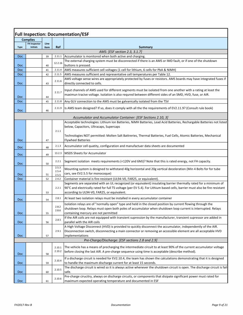
Doc 39 2.11.1 Accumulator is monitored when both active and charging.
Doc 4012.2.16
The external charging system must be disconnected if there is an AMS or IMD fault, or if one of the shutdown buttons is pressed.
Doc 41 2.11.4 AMS measures sufficient cell voltages (1 cell for lithium, 6 cells for PbA & NiMH)Doc 42 2.11.5 AMS measures sufficient and representative cell temperatures per Table 12.
Doc 432.11.6
AMS voltage sense wires are appropriately protected by fuses or resistors. AMS boards may have integrated fuses if directly connected to cells.
Doc 44
2.11.7Input channels of AMS used for different segments must be isolated from one another with a rating at least the maximun tracive voltage. Isolation is also requred between different sides of an SMD, HVD, fuse, or AIR.
Doc 45 2.11.8 Any GLV connection to the AMS must be galvanically isolated from the TSV
Doc 462.11.9 Is AMS team designed? If so, does it comply with all the the requirements of EV2.11.9? (Consult rule book)
Doc 47
2.1.1
Acceptable technologies: Lithium Ion Batteries, NiMH Batteries, Lead Acid Batteries, Rechargable Batteries not listed below, Capacitors, Ultracaps, Supercaps
Technologies NOT permitted: Molten Salt Battreries, Thermal Batteries, Fuel Cells, Atomic Batteries, Mechanical Flywheel Batteries
Doc 48 2.1.3 Accumulator cell quatity, configuration and manufactuer data sheets are documented
Doc 49 13.2.3 MSDS Sheets for Accumulator
Doc 502.2.1 Segment isolation meets requirements (<120V and 6MJ)? Note that this is rated energy, not FH capacity.
Doc 51
2.5.32.5.42.5.5
Mounting system is designed to withstand 40g horizontal and 20g vertical deceleration (Min 4 Bolts for for tube cars, see EV2.5.5 for monocoque)
Doc 52 2.4.2 Container material is fire-resistant (UL94-V0, FAR25, or equivalent).
53
2.2.1Segments are separated with an UL recognized (or equivalent) insulating barrier thermally rated for a minimum of 90°C and electrically rated for full TS voltage (per EV 5.4). For Lithium based cells, barrier must also be fire resistant according to UL94-V0, FAR25, or equivalent.
Doc 54 2.8.1 At least two isolation relays must be installed in every accumulator container
Doc 55
2.8.22.8.6
Isolation relays are of "normally open" type and held in the closed position by current flowing through the shutdown loop. Relays must open both poles of accumulator when shutdown loop current is interrupted. Relays containing mercury are not permitted
Doc 562.8.5
If the AIR coils are not equipped with transient supression by the manufacturer, transient supressor are added in parallel with the AIR coils
Doc 57
2.9.1A High Voltage Disconnect (HVD) is provided to quickly disconnect the accumulator, independently of the AIR. Disconnection switch, disconnecting a main connector or removing an accessible element are all acceptable HVD implementations
Doc 58
2.10.12.10.2
The vehicle has a means of precharging the intermediate circuit to at least 90% of the current accumulator voltage before closing the last AIR. A pre-charge sequence using time is acceptable (describe method).
Doc 592.10.4
If a discharge circuit is needed for EV2.10.4, the team has shown the calculations demonstrating that it is designed to handle the maximum discharge current for at least 15 seconds.
Doc 602.10.5
The discharge circuit is wired so it is always active whenever the shutdown circuit is open. The discharge circuit is fail-safe.
Doc 612.10.6
Pre-charge cirucitry, always on discharge circuits, or components that disipate significant power must rated for maximum expected operating temperature and documented in ESF
Accumulator and Accumulator Container: [ESF Sections 2.10, 3]
Pre-Charge/Discharge: [ESF sections 2.8 and 2.9]
AMS: [ESF section 2.3, 3.1.7]
FH2017-Rev B Documentation Page 10 of 21
TypeFH Inspector
Initials
Full Inspection: Documentation/ESFComplies
Ref SummaryLine Item
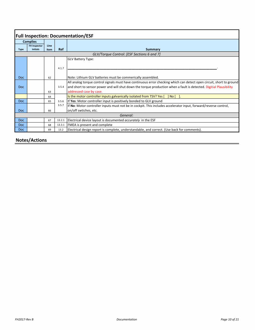
Doc 62
4.1.7
GLV Battery Type:
__________________________________________.
Note: Lithium GLV batteries must be commerically assembled.
Doc63
3.5.4All analog torque control signals must have continuous error checking which can detect open circuit, short to ground and short to sensor power and will shut down the torque production when a fault is detected. Digitial Plausibility addressed case by case.
64 Is the motor controller inputs galvanically isolated from TSV? Yes [ ] No [ ]. Doc 65 If Yes: Motor controller input is positively bonded to GLV ground
Doc 66
If No: Motor controller inputs must not be in cockpit. This includes accelerator input, forward/reverse control, on/off swtiches, etc.
Doc 67 13.2.1 Electrical device layout is documented accurately in the ESFDoc 68 13.3.1 FMEA is present and completeDoc 69 13.2 Electrical design report is complete, understandable, and correct. (Use back for comments).
Notes/Actions
3.5.63.5.7
General:
GLV/Torque Control: [ESF Sections 6 and 7]
FH2017-Rev B Inspection Page 11 of 21
TypeFH Inspector
Initials
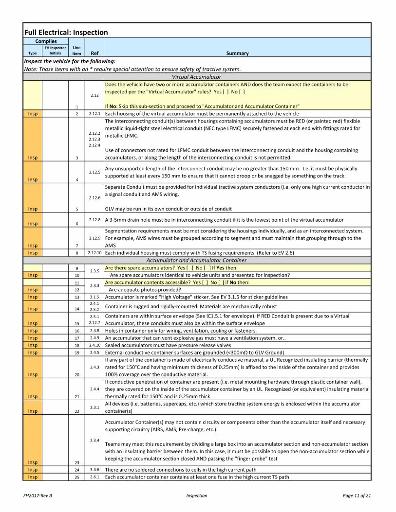
1
2.12
Does the vehicle have two or more accumulator containers AND does the team expect the containers to be inspected per the "Virtual Accumulator" rules? Yes [ ] No [ ]
If No: Skip this sub-section and proceed to "Accumulator and Accumulator Container"Insp 2 2.12.1 Each housing of the virtual accumulator must be permanently attached to the vehicle
Insp 3
2.12.22.12.32.12.4
The Interconnecting conduit(s) between housings containing accumulators must be RED (or painted red) flexible metallic liquid-tight steel electrical conduit (NEC type LFMC) securely fastened at each end with fittings rated for metallic LFMC.
Use of connectors not rated for LFMC conduit between the interconnecting conduit and the housing containing accumulators, or along the length of the interconnecting conduit is not permitted.
Insp 4
2.12.5Any unsupported length of the interconnect conduit may be no greater than 150 mm. I.e. it must be physically supported at least every 150 mm to ensure that it cannot droop or be snagged by something on the track.
Insp 5
2.12.6
Separate Conduit must be provided for individual tractive system conductors (i.e. only one high current conductor in a signal conduit and AMS wiring.
GLV may be run in its own conduit or outside of conduit
Insp 62.12.8 A 3-5mm drain hole must be in interconnecting conduit if it is the lowest point of the virtual accumulator
Insp 7
2.12.9Segmentation requirements must be met considering the housings individually, and as an interconnected system. For example, AMS wires must be grouped according to segment and must maintain that grouping through to the AMS
Insp 8 2.12.10 Each individual housing must comply with TS fusing requirements. (Refer to EV 2.6)
9 Are there spare accumulators? Yes [ ] No [ ] If Yes then:Insp 10 Are spare accumulators identical to vehicle units and presented for inspection?
11 Are accumulator contents accessible? Yes [ ] No [ ] if No then:Insp 12 Are adequate photos provided?Insp 13 3.1.5 Accumulator is marked "High Voltage" sticker. See EV 3.1.5 for sticker guidelines
Insp 142.4.12.5.2 Container is rugged and rigidly-mounted. Materials are mechanically robust
Insp 152.5.1
2.12.7Containers are within surface envelope (See IC1.5.1 for envelope). If RED Conduit is present due to a Virtual Accumulator, these conduits must also be within the surface envelope
Insp 16 2.4.8 Holes in container only for wiring, ventilation, cooling or fasteners. Insp 17 2.4.9 An accumulator that can vent explosive gas must have a ventilation system, or..Insp 18 2.4.10 Sealed accumulators must have pressure release valvesInsp 19 2.4.5 External conductive container surfaces are grounded (<300mΩ to GLV Ground)
Insp 20
2.4.3If any part of the container is made of electrically conductive material, a UL Recognized insulating barrier (thermally rated for 150°C and having minimum thickness of 0.25mm) is affixed to the inside of the container and provides 100% coverage over the conductive material.
Insp 21
2.4.4If conductive penetration of container are present (i.e. metal mounting hardware through plastic container wall), they are covered on the inside of the accumulator container by an UL Recognized (or equivalent) insulating material thermally rated for 150°C and is 0.25mm thick
Insp 222.3.1
All devices (i.e. batteries, supercaps, etc.) which store tractive system energy is enclosed within the accumulator container(s)
Insp 23
2.3.4
Accumulator Container(s) may not contain circuity or components other than the accumulator itself and necessary supporting circuitry (AIRS, AMS, Pre-charge, etc.).
Teams may meet this requirement by dividing a large box into an accumulator section and non-accumulator section with an insulating barrier between them. In this case, it must be possible to open the non-accumulator section while keeping the accumulator section closed AND passing the "finger probe" test
Insp 24 3.4.6 There are no soldered connections to cells in the high current pathInsp 25 2.6.1 Each accumulator container contains at least one fuse in the high current TS path
Full Electrical: InspectionComplies
Ref Summary
2.3.5
Inspect the vehicle for the following: Note: Those items with an * require special attention to ensure safety of tractive system.
Accumulator and Accumulator Container
Virtual Accumulator
Line Item
2.3.3
FH2017-Rev B Inspection Page 12 of 21
TypeFH Inspector
Initials
Full Electrical: InspectionComplies
Ref SummaryLine Item
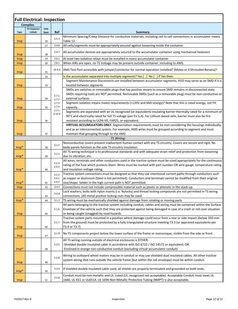
Insp 265.5.3
Minimum Spacing/Creep Distance for conductive materials, including cell to cell connections in accumulator meets Table 12
27 2.4.6 All cells/segments must be appropriately secured against loosening inside the container
Insp 282.4.7 All accumulator devices are appropriately secured to the accumulator container using mechanical fasteners
Insp 29 3.6.1 At least two isolation relays must be installed in every accumulator containerInsp 30 2.8.1 When AIRs are open, no TS Voltage may be present outside container, including to AMS.
Insp 3110.4.4 AMS Test Port accessible with jumper/connector for normal operation installed? (Molex or 4 Shrouded Banana)?
32 Is the accumulator separated into multiple segments? Yes [ ] No [ ] If Yes then:
Insp 33
Segment Maintenance Disconnects are installed between accumulator segments. HVD may serve as an SMD if it is located between segments
Insp 34
SMDs are switches or removable plugs that has positive means to ensure SMD remains in disconnected state. SMDs requiring tools are NOT permitted. Removable SMDs (such as a removable plug) must be non-conductive on external surfaces
Insp 35
Segment isolation means meets requirements (<120V and 6MJ energy)? Note that this is rated energy, not FH capacity.
Insp 36
Segments are separated with an UL recognized (or equivalent) insulating barrier thermally rated for a minimum of 90°C and electrically rated for full TS voltage (per EV 5.4). For Lithium based cells, barrier must also be fire resistant according to UL94-V0, FAR25, or equivalent.
Insp 37
VIRTUAL ACCUMULATORS ONLY: Segmentation requirements must be met considering the housings individually, and as an interconnected system. For example, AMS wires must be grouped according to segment and must maintain that grouping through to the AMS
Insp* 383.1.1
Nonconductive covers prevent inadvertent human contact with any TS circuitry. Covers are secure and rigid. No body panels function as the sole TS circuitry insulation.
Insp* 393.2.1
All TS wiring technique is to professional standards and with adequate strain relief and protection from loosening due to vibration, etc.
Insp* 40
3.2.33.4.2
All wires, terminals and other conductors used in the tractive system must be sized appropriately for the continuous rating of the fuse which protects them. Wires must be marked with part number OR wire gauge, temperature rating and insulation voltage rating.
Insp* 41
3.2.23.4.13.4.2
Tractive system connections must be designed so that they use intentional current paths through conductors such as copper or aluminum (Steel is not permitted). Conductors and terminals cannot be modified from their original size/shape. Solder in the high current path is NOT permitted.
Insp 42 3.4.3 Connections must not include compressible material such as plastic or phenolic in the stack-up.
433.4.4
Lock washers, bolts with nylon inserts (i.e. Nylocks) and thread locking compounds are not permitted in TS wiring connections. (All-metal positive locking nuts may be used.
Insp* 44 3.1.2 TS wiring must be mechanically shielded against damage from rotating or moving parts
Insp 45
3.1.6All parts belonging to the tractive system including conduit, cables and wiring must be contained within the Surface Envelope of the vehicle such that they are protected against being damaged in case of a crash or roll-over situation or being caught (snagged) by road hazards.
Insp 46
3.1.7Tractive system parts mounted in a position where damage could occur from a rear or side impact (below 350 mm from the ground) must be protected by a fully triangulated structure meeting T3.3 (or approved equivalents per T3.4 or T3.7)
Insp 473.1.9 No TS components project below the lower surface of the frame or monocoque, visible from the side or front.
Insp* 48
3.2.5All TS wiring running outside of electrical enclosures is EITHER:-Shielded double-insulated cable in accordance with ISO 6722 / ISO 14572 or equivalent; OR-Enclosed in orange non-conductive conduit (excluding virtual accumulator conduit)
Insp 49
3.2.8Wiring to outboard wheel motors may be in conduit or may use shielded dual insulated cables. All other tractive system wiring that runs outside the vehicle frame (but within the roll envelope) must be within conduit.
Insp* 503.2.9 If shielded double insulated cable used, all shields are properly terminated and grounded on both ends.
Insp 513.2.6
Conduit must be non-metallic and UL Listed (UL recognized not acceptable). Acceptable Conduit must meet UL 1660, UL 651 or UL651A. UL 1696 Non-Metallic Protective Tubing (NMPT) is also acceptable.
TS Wiring:
2.7.12.7.22.7.32.7.42.2.1
2.12.9
FH2017-Rev B Inspection Page 13 of 21
TypeFH Inspector
Initials
Full Electrical: InspectionComplies
Ref SummaryLine Item
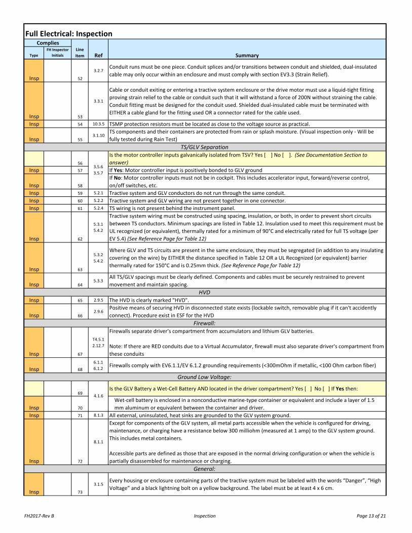
Insp 52
3.2.7Conduit runs must be one piece. Conduit splices and/or transitions between conduit and shielded, dual-insulated cable may only occur within an enclosure and must comply with section EV3.3 (Strain Relief).
Insp 53
3.3.1
Cable or conduit exiting or entering a tractive system enclosure or the drive motor must use a liquid-tight fitting proving strain relief to the cable or conduit such that it will withstand a force of 200N without straining the cable. Conduit fitting must be designed for the conduit used. Shielded dual-insulated cable must be terminated with EITHER a cable gland for the fitting used OR a connector rated for the cable used.
Insp 54 10.3.5 TSMP protection resistors must be located as close to the voltage source as practical.
Insp 553.1.10
TS components and their containers are protected from rain or splash moisture. (Visual inspection only - Will be fully tested during Rain Test)
56
Is the motor controller inputs galvanically isolated from TSV? Yes [ ] No [ ]. (See Documentation Section to answer)
Insp 57 If Yes: Motor controller input is positively bonded to GLV ground
Insp 58
If No: Motor controller inputs must not be in cockpit. This includes accelerator input, forward/reverse control, on/off switches, etc.
Insp 59 5.2.1 Tractive system and GLV conductors do not run through the same conduit.Insp 60 5.2.2 Tractive system and GLV wiring are not present together in one connector.Insp 61 5.2.4 TS wiring is not present behind the instrument panel.
Insp 62
5.3.15.4.2
Tractive system wiring must be constructed using spacing, insulation, or both, in order to prevent short circuits between TS conductors. Minimum spacings are listed in Table 12. Insulation used to meet this requirement must be UL recognized (or equivalent), thermally rated for a minimum of 90°C and electrically rated for full TS voltage (per EV 5.4) (See Reference Page for Table 12)
Insp 63
5.3.25.4.2
Where GLV and TS circuits are present in the same enclosure, they must be segregated (in addition to any insulating covering on the wire) by EITHER the distance specified in Table 12 OR a UL Recognized (or equivalent) barrier thermally rated for 150°C and is 0.25mm thick. (See Reference Page for Table 12)
Insp 645.3.3
All TS/GLV spacings must be clearly defined. Components and cables must be securely restrained to prevent movement and maintain spacing.
Insp 65 2.9.5 The HVD is clearly marked "HVD".
Insp 662.9.6
Positive means of securing HVD in disconnected state exists (lockable switch, removable plug if it can't accidently connect). Procedure exist in ESF for the HVD
Insp 67
T4.5.12.12.7
Firewalls separate driver's compartment from accumulators and lithium GLV batteries.
Note: If there are RED conduits due to a Virtual Accumulator, firewall must also separate driver's compartment from these conduits
Insp 686.1.16.1.2 Firewalls comply with EV6.1.1/EV 6.1.2 grounding requirements (<300mOhm if metallic, <100 Ohm carbon fiber)
69Is the GLV Battery a Wet-Cell Battery AND located in the driver compartment? Yes [ ] No [ ] If Yes then:
Insp 70
Wet-cell battery is enclosed in a nonconductive marine-type container or equivalent and include a layer of 1.5 mm aluminum or equivalent between the container and driver.
Insp 71 8.1.3 All external, uninsulated, heat sinks are grounded to the GLV system ground.
Insp 72
8.1.1
Except for components of the GLV system, all metal parts accessible when the vehicle is configured for driving, maintenance, or charging have a resistance below 300 milliohm (measured at 1 amp) to the GLV system ground. This includes metal containers.
Accessible parts are defined as those that are exposed in the normal driving configuration or when the vehicle is partially disassembled for maintenance or charging.
Insp 73
3.1.5Every housing or enclosure containing parts of the tractive system must be labeled with the words “Danger”, “High Voltage” and a black lightning bolt on a yellow background. The label must be at least 4 x 6 cm.
4.1.6
General:
Ground Low Voltage:
TS/GLV Separation
Firewall:
HVD
3.5.63.5.7

FH2017-Rev B Inspection Page 14 of 21
TypeFH Inspector
Initials
Full Electrical: InspectionComplies
Ref SummaryLine Item
Insp74
5.4.1All electrical insulating material must be appropriate and adequately robust for the application in which it is used. No electrical tape or coating used alone for insulation
Insp 75 6.1.6 Fuses must be physically located at the end of the wiring closest to an uncontrolled energy sourceInsp 76 6.1 Physically inspect key TS fuses (That were not inspected in the accumulator)Insp 77 6.1 Physically inspect key GLV fuses
Notes/Actions

FH2017-Rev B Pouch Cells Page 15 of 21
TypeFH Inspector
Initials
Doc 1 2.1.2 Are pouch type lithium cells used? Yes [ ] No [ ]
Doc 2
2.1.2
Is the accumulator using pouch cells commercially constructed and specifically approved by the Rules Committee?
Yes [ ] No [ ]
If Yes, no further inspection needed. If No, continue inspecting pouch cells according to this inspection page.
Insp 3 11.1.1 Cells in a stack are arranged face-to-face (Edge-To-Edge is NOT allowed)
Insp 4
11.1.2
Mechanical restraining system of the pouch cell must-Be capable of applying >=10 psi without yielding for all temps <=150°C-Allow the stack to expand 8%-12% in volume before reaching 10 psi-Use fire retardant and creep immune materials-Not impinge on the cell separator internal to the cell-Be electrically insulated from the cells (if made of conductive materials)-Documented in the ESF
Note: Variance may be granted against items in 11.1.2 if the team has a mechanical analysis of the proposed cell mounting structures AND EITHER-Datasheet from the manufacturer recommendations for assembly OR-A letter from the manufacturer with similar info.
Insp 511.1.3
A fire resistant soft elastic filler material is present between every cell. Material is evenly distributed through the stack and applying even pressure to each cell surface
Insp 6 11.1.4 Cell tabs are mechanically restrained and cannot move relative to the cell
Insp 711.1.4
Cell tabs are connected above the level of the tab insulator (metallic parts of the battery assembly may not bridge the insulation gap provided by the tab insulator)
Insp 8 11.1.4 Cell Tabs are insulated to prevent accidentally short circuit of adjacent cells
Insp 911.1.6
Cells held in position using a repeated frame (or equivalent). Frame does not change shape of the cell, impinge on the cell separator, or allow the edge of the cell to move in relation to the rest of the cell
Insp 1011.1.8 No visible evidence of pouch cell damage due to handling or wear. No metal filing or other FOD near pouch cells
Insp 1111.1.9 Entire stack is firmly anchored in the accumulator enclosure and clean of shavings or filings from manufacturer
Doc 12 11.1.10 All compliance information is in ESF
Notes/Actions
Note: Accumulators utilizing pouch type lithium ion cells are subject to the below rules. Do NOT complete this section if prismatic or cylindrical cells are used.
Full Electrical: Pouch CellsComplies
Ref SummaryLineItem

FH2017-Rev B Demonstration Page 16 of 21
TypeFH Inspector
Initials
DemoStep 1
A.6.4.2Team should demonstrate their jack stand procedure. (Quick jack is not allowed for powered testing)
DemoStep 2
9.2.12.10.37.7.2
With meter attached to TSMPs, team should energize car. Confirm Pre-Charge operated. There should be a second action to put the car into “Ready-To-Drive” mode
DemoStep 3
3.5.2Ensure torque control is actuated by a right foot pedal.
DemoStep 4
N/AAsk team to slightly depress the pedal to show drive wheel will rotate.
DemoStep 5
3.5.3Ask team to release pedal to demonstrate pedal returns to original position. Ensure presence of positive stop.
DemoStep 6
3.5.43.5.5
Ask team to slightly depress the pedal to rotate drive wheel. Interrupt torque command signal. Torque production should stop within 1 sec . Power down the vehicle
DemoStep 7
N/APerform the steps 8-13 to demonstrate safety circuit operation. Note: Each time the car is energized, ensure two actions must be taken to achieve “Ready to Drive”
DemoStep 8
7.1.17.1.4
Energize the vehicle. Slightly depress the right foot pedal to rotate wheels. Open the Brake Over Travel Switch. AIRs should open and wheels should spin freely. Ensure the driver cannot reset the brake over travel switch with foot or hand
DemoStep 9
7.1.27.7.1 Reset Brake Over Travel Switch and energize the vehicle. Open the GLV Master Switch. AIRs should open.
DemoStep 10
7.4.1Close GLV Switch and energize the vehicle. Open the TSMS. Air should open
DemoStep 11
7.6.57.7.3
Close the TSMS and energize the vehicle. Ask the team to open the Big Red Button in the cockpit. AIRs should open. Close the Big Red Button in the cockpit and confirm vehicle is NOT "Ready to Drive". Perform second action to achieve “Ready to Drive.”
DemoStep 12
2.10.1Open the cockpit big red button during the pre-charge stage. Ensure the Pre-charge is disabled.
DemoStep 13
2.11.22.11.37.1.410.4
With car de-energized, attach AMS test connector. Energize the vehicle. Induce an AMS fault using the AMS test setup using AMS trip levels from the ESF. AIRs should open. Remove fault. Ask team to reset AMS. Ensure driver cannot reset AMS.
DemoStep 14
N/ARemove meter from TSMP and the AMS test connector. Connect IMD test box
DemoStep 15
7.1.47.9.59.4.19.4.2
10.1.2
Induce fault to high pole of TS (level based on TS Voltage). Ensure shutdown occurs within 30 seconds. Fault light in cockpit should illuminate. Remove fault. Ensure the TS system does not re-energize (i.e. latches off due to fault)
DemoStep 16
7.1.47.9.59.4.19.4.2
10.1.2
Induce fault to low side of TS (level based on TS Voltage). Ensure shutdown occurs within 30 seconds. Fault light in cockpit should illuminate. Remove fault. Ensure the TS system does not re-energize (i.e. latches off due to fault)
DemoStep 17
7.9.5Ensure driver cannot reset IMD
DemoStep 18
N/AEnsure vehicle is completely de-energized and remove vehicle from jack stands. All panels in the vicinity of the HVD should be attached.
DemoStep 19
2.9.22.9.32.9.4
Ask the team to designate someone other the RSO or Chief Engineer to remove the HVD in under 10 seconds from a starting position 10 feet away from the vehicle. Replace HVD
DemoStep 20
7.1.1
HYBRIDS ONLY (to be performed at Noise Test after completion of Electrical Tech): Enable the IC engine. Press one of the side mounted BRBs. Ensure the IC engine turns off (Inspector optionally may also use a DMM to ensure fuel pump is disabled if it is easily accessible. Repeat for the other side mounted button and the cockpit BRB. Note to Inspector: If electric vehicle, mark as N/A. If hybrid, leave blank. Electrical Inspector present Noise Test will mark their initial after completion of Noise Test.
Demonstration (See attached procedure that covers these rules)Complies
Ref SummaryThe following is the Final Demonstration. The team should be able to perform the following actions upon request.
Ability to complete these actions constitute passing the applicable rules.

FH2017-Rev B Demonstration Page 17 of 21
OPTIONAL TEST: The insulation resistance between the tractive system and control system ground may be measured. The available measurement voltages are 250 V and 500 V. All cars with a maximum nominal operation voltage below 500 V will be measured with the next available voltage level. For example, a 175 V system will be measured with 250 V; a 300 V system will be measured with 500 V etc.The measured insulation resistance is >= 500 ohm/volt related to the maximum nominal tractive system operation voltage. Measurement:________________________
The following is an optional test that may be performed at the discretion of the Inspector under advisement of the Chief Engineer to confirm insulation and isolation between GLV and TS
Demo
Notes/Actions
10.2.110.2.2

FH2017-Rev B Demonstration Page 18 of 21
3.5.2 Torque control sensor actuated by a right foot pedal3.5.3 Foot pedal returns to original position when not actuated and has positive stops to protect sensor
3.5.4All plausibility detections schemes must detect and shutdown torque production within 1 second of the errors first occurrence or loss of communication. This includes both digital and analog torque control methods
Teams must be prepared to demonstrate error detection at Electrical Tech Inspection. Unplugging a connector is an acceptable method of demonstrationDescription of demonstration method:
7.1.1 The brake over-travel switch shuts down the tractive system, the IC engine and the fuel pumps??? Check that motor spins freely when TS is deactivated.
7.1.27.7.1
The GLV system must be energized in order to activate the tractive system. If the GLV system shut down, the tractive system must de-activate immediately.
7.4.1 The TSMS must open the Tractive System shutdown circuit.2.9.22.9.32.9.4
The team can remove the HVD in under 10 seconds, from the ready-to-drive condition, without the use of tools.
7.6.5The driver must be able to re-activate or reset the tractive system from within the cockpit without the assistance of any other person except for situations in which the AMS or IMD have shut down
7.7.27.7.3
At least one action in addition to enabling the shutdown circuits is required to set the car to ready-to-drive mode. A start button shall not be such that it can inadvertently be left in the “on” position.
2.10.1 The precharge is disabled by an opened shutdown circuit.
2.10.3Pre-Charge circuit must operate regardless of the sequence of operation used to energize the vehicle (i.e. restarting after automatic shut down of safety circuit)
7.8.17.8.2 Shutdown circuit operates to state diagram in Figure 31
2.11.22.11.3
AMS disables all electrical systems, disables IC drive system, and opens AIRs within 60 seconds. AMS remains disabled until manually reset by someone other than driver (i.e. reset button not accessible to driver when seated in normal racing position)
10.4 Does AMS trip at level documented in ESF?
7.1.4The driver must not be able to re-activate the tractive system from within the car in case of an AMS, Brake Over Travel or IMD fault. Wireless reset shutdown circuit is not permitted
7.9.5TS remains inactive until manually reset by other than the driver (IMD Fault). Driver must not be able to reset an IMD fault from within the car.
7.9.5 Removing a (test) ground fault must not re-energize the TS.9.4.19.4.2
A red indicator light in the cockpit indicates IMD status. It is visible in bright sunlight, and marked "IMD" or "GFD".
The IMD test is passed if the IMD shuts down the tractive system within 30 seconds at a fault resistance of 250 ohm/volt (50% below the response value) - Note: Proper wiring proven through successful testing of the IMD
IMD test. Shuts down HV?_______ Latches off?________ Labeled cockpit light?_______OPTIONAL TEST: The insulation resistance between the tractive system and control system ground may be measured. The available measurement voltages are 250 V and 500 V. All cars with a maximum nominal operation voltage below 500 V will be measured with the next available voltage level. For example, a 175 V system will be measured with 250 V; a 300 V system will be measured with 500 V etc.The measured insulation resistance is >= 500 ohm/volt related to the maximum nominal tractive system operation voltage
The following is for REFERENCE ONLY with regards to demonstration requirements.
10.2.110.2.2
10.1.2
Safety Circuit/Shutdown
IMD
AMS
3.5.5
Torque Control:
FH2017-Rev B Tools and Charging Page 19 of 21
TypeFH Inspector
Initials
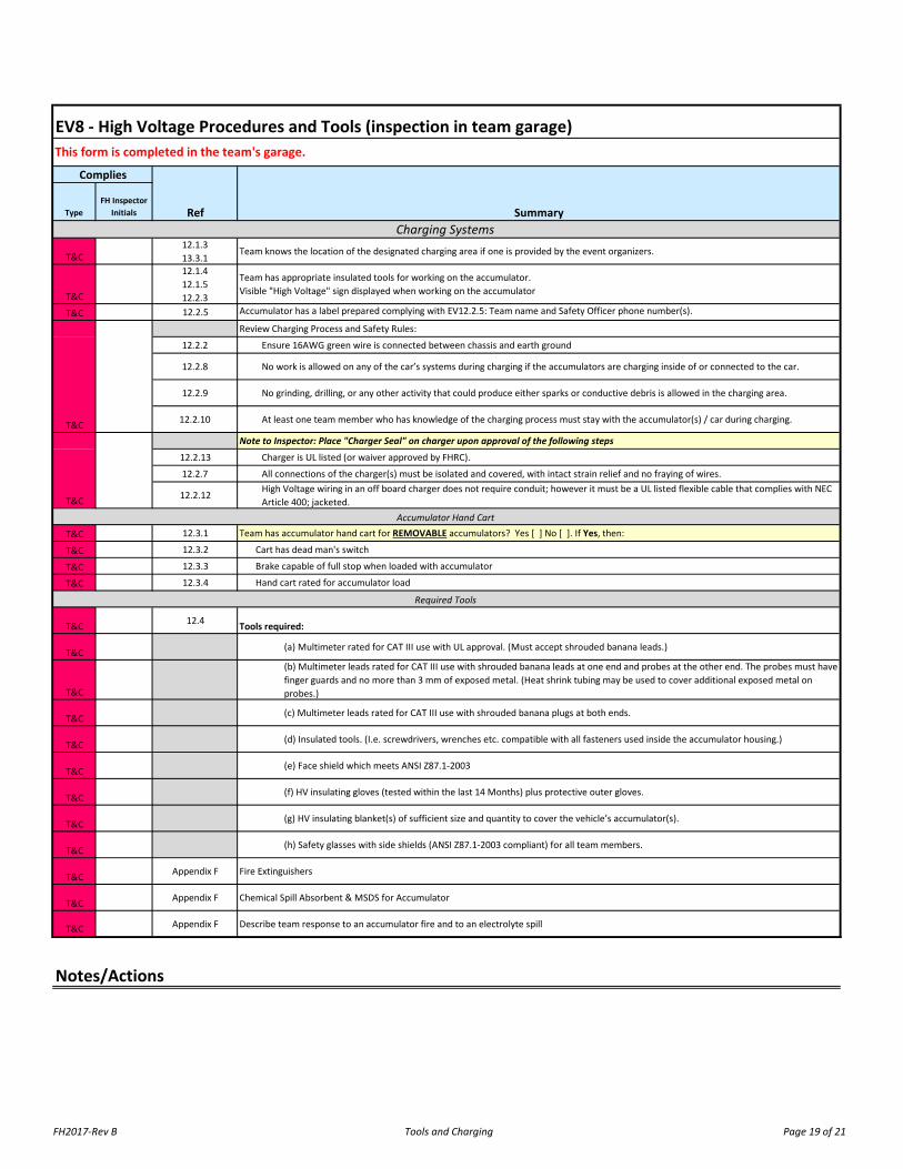
T&C12.1.313.3.1
Team knows the location of the designated charging area if one is provided by the event organizers.
T&C
12.1.412.1.512.2.3
Team has appropriate insulated tools for working on the accumulator.Visible "High Voltage" sign displayed when working on the accumulator
T&C 12.2.5 Accumulator has a label prepared complying with EV12.2.5: Team name and Safety Officer phone number(s).
Review Charging Process and Safety Rules:
12.2.2 Ensure 16AWG green wire is connected between chassis and earth ground
12.2.8 No work is allowed on any of the car’s systems during charging if the accumulators are charging inside of or connected to the car.
12.2.9 No grinding, drilling, or any other activity that could produce either sparks or conductive debris is allowed in the charging area.
12.2.10 At least one team member who has knowledge of the charging process must stay with the accumulator(s) / car during charging.
Note to Inspector: Place "Charger Seal" on charger upon approval of the following steps
12.2.13 Charger is UL listed (or waiver approved by FHRC).
12.2.7 All connections of the charger(s) must be isolated and covered, with intact strain relief and no fraying of wires.
12.2.12High Voltage wiring in an off board charger does not require conduit; however it must be a UL listed flexible cable that complies with NEC Article 400; jacketed.
T&C 12.3.1 Team has accumulator hand cart for REMOVABLE accumulators? Yes [ ] No [ ]. If Yes, then:
T&C 12.3.2 Cart has dead man's switch
T&C 12.3.3 Brake capable of full stop when loaded with accumulator
T&C 12.3.4 Hand cart rated for accumulator load
T&C 12.4 Tools required:
T&C (a) Multimeter rated for CAT III use with UL approval. (Must accept shrouded banana leads.)
T&C
(b) Multimeter leads rated for CAT III use with shrouded banana leads at one end and probes at the other end. The probes must have finger guards and no more than 3 mm of exposed metal. (Heat shrink tubing may be used to cover additional exposed metal on probes.)
T&C (c) Multimeter leads rated for CAT III use with shrouded banana plugs at both ends.
T&C (d) Insulated tools. (I.e. screwdrivers, wrenches etc. compatible with all fasteners used inside the accumulator housing.)
T&C (e) Face shield which meets ANSI Z87.1-2003
T&C (f) HV insulating gloves (tested within the last 14 Months) plus protective outer gloves.
T&C (g) HV insulating blanket(s) of sufficient size and quantity to cover the vehicle’s accumulator(s).
T&C (h) Safety glasses with side shields (ANSI Z87.1-2003 compliant) for all team members.
T&C Appendix F Fire Extinguishers
T&C Appendix F Chemical Spill Absorbent & MSDS for Accumulator
T&C Appendix F Describe team response to an accumulator fire and to an electrolyte spill
Notes/Actions
Charging Systems
EV8 - High Voltage Procedures and Tools (inspection in team garage)
Required Tools
Accumulator Hand Cart
This form is completed in the team's garage.
Complies
Ref Summary
T&C
T&C
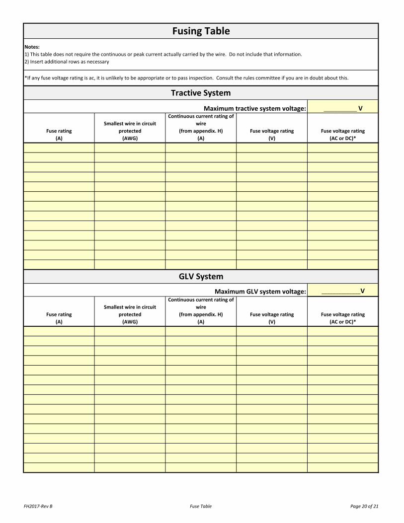
FH2017-Rev B Fuse Table Page 20 of 21
____________ V
Fuse rating(A)
Smallest wire in circuit protected
(AWG)
Continuous current rating of wire
(from appendix. H)(A)
Fuse voltage rating(V)
Fuse voltage rating(AC or DC)*
______________V
Fuse rating(A)
Smallest wire in circuit protected
(AWG)
Continuous current rating of wire
(from appendix. H)(A)
Fuse voltage rating(V)
Fuse voltage rating(AC or DC)*
Tractive System
GLV System
Maximum GLV system voltage:
Maximum tractive system voltage:
Fusing TableNotes:1) This table does not require the continuous or peak current actually carried by the wire. Do not include that information.2) Insert additional rows as necessary
*If any fuse voltage rating is ac, it is unlikely to be appropriate or to pass inspection. Consult the rules committee if you are in doubt about this.

FH2017-Rev B Inspectors Reference Page 21 of 21
wire Max fuse
24 5
22 720 1018 1416 2014 2812 4010 558 806 1054 1403 1652 1901 220
1/0 2602/0 3003/0 3504/0 405
250 cmils 455300 cmils 505
EmergencyIf an emergency crew is within sight, make contact.
Otherwise Dial 911
Inspectors Reference