Embed Size (px)
Citation preview

FORMING RESERVED OUTPUT SIGNAL OF AN ATOMIC CLOCK ENSEMLE
K. Mishagin, I. Chernyshev, V. Soloviov, S. Podogova
6th International Symposium “METROLOGY OF TIME AND SPACE”
«Vremya-CH», Nizhny Novgorod, Russia

MotivationModern atomic clock ensemble etalons are required to produce continuous output signal� long continuous measurements� critical applications: communication with space
stations, etc.
Requirements to reserving system:
� Failure of certain atomic clock must not lead to phase/frequency jumps of the output signal
� Designed system is desired to be full-automatic� It is attractive to get physical signal possessing
frequency stability of ensemble weighted average

1 PPSCLOCK-1
CLOCK-2
CLOCK-n
Sw
itch
Computer
Phase comparator
orTime interval
counter
5 MHz 1 PPS
5 MHzAOG-1
AOG-2
AOG-n
1 PPS
5 MHz
1 PPS
5 MHz
Standard approach to output signal reserving

Standard approach to output signal reserving
Disadvantages:
• Long time for input signal analysis and commutation • Unavoidable phase/frequency shift during commutation• System complexity

Alternative approach∆f1,i
∆f2,i
∆f3,i
CLOCK-1
CLOCK-2
CLOCK-n
CLOCK-3M
ulti-
cha
nne
l pha
se (
fre
que
ncy)
com
para
tor
Pro
cess
or Voltage controlled quartz
oscillator5 MHz
DAC
Former of output signals
f1
fn
5, 10, 100 MHz, 1 Hz
1 PPS synch.
f2
f3
Scheme for output signal reserving in atomic clock ensemble
Real-time atomic clock
combinerVCH-317

Advantages:
� Fast detection and program detaching of failure signal� No phase/frequency shifts due to attaching/detaching
input signals� Can be realized in one device and reserved additionally � Frequency stability of output signal can be improved (it
can be better than the stability of the best reference standard)

PID-control algorithm for frequency stabilization
( ) ( )( )
∆
−=
+−−−−−∆+=
−
−−−+
1
2111
1
2DACDAC
nnn
nnnd
nnp
ni
nn
xxy
yyykyykyk
τ– relative frequency difference
– programmed frequency offset Loop sample time τ = 10 ms
Output frequency calculation
∑=
++=N
nn
Nn fwtf
1out νδ
ki, kp, kd are optimized Introduced phase noise and AVAR are minimized

Frequency instability introduced by the system
100
101
102
103
10-17
10-16
10-15
10-14
10-13
τ, s
σ y(τ
)HROG-5
AOG-110
VCH-317
Time TechClean-up osc.
No temperature stab.
in the room

No shifts in phase and frequency after adding/removing reference signal

Optimal weights selection problem
min2317
1
222out →+=∑
=σσσ
N
iiiw
∑=
−
−=
N
kk
iiw
1
2
2
)(
)()(
τσ
τστ
Output signal frequency instability is minimized for single averaging time only!Possible solutions:
1) Virtual atomic time scale + control of auxiliary oscillator 2) Multi-scale control
Frequency stability of the output signal
∑=
=N
nnn fwf
1out
∑=
−=∆N
n
Sn
Snk ywU
1
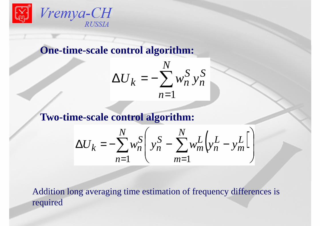
One-time-scale control algorithm:
Two-time-scale control algorithm:
( )∑ ∑= =
−−−=∆
N
n
N
m
Lm
Ln
Lm
Sn
Snk yywywU
1 1
Addition long averaging time estimation of frequency differences is required

( )∑ ∑= =
−−−=∆
N
n
N
m
Lm
Ln
Lm
Sn
Snk yywywU
1 1
Weights estimation for two-scale frequency control:
∑=
−
−=
N
k
Sk
SnS
nw
1
2
2
)(
)(
τσ
τσShort time:
Long time: ∑=
−
−
= N
k
Lk
LnL
nw
1
2
2
)~(
)~(
τσ
τσ
Estimation of frequency stability of reference signals is needed

Modeling
τS = 1 secτL = 20000 sec
Two types of reference signals: 4 + 4

∑=
−
−=
N
k
Sk
SnS
nw
1
2
2
)(
)(
τσ
τσ
∑=
−
−
= N
k
Lk
LnL
nw
1
2
2
)~(
)~(
τσ
τσ
Results of modeling. Dynamics of weights

Results of modeling
Two-scale frequency control

Summary
� Atomic clock combiner system seems to be effective for output signal reserving (fast detection and exclusion of invalid reference signals, no phase/frequency jumps)
� Simple modification of the algorithm allows to obtain output signal frequency stability better than the best input signal has for all τ

THANK YOU FOR YOUR ATTENTION!
WELCOME TO THE POSTER SECTION
S. Podogova, K. MishaginCALIBRATION OF FREQUENCY STANDARD WITH THE USE OF
GLONASS/GPS RECEIVER: ALGORITHMS COMPARISON AND EXP ERIMENT
K. Mishagin, I. Chernyshev, A. Belyaev, S. Medvedev, P. SmirnovACCURACY ANALYSIS OF THREE-CORNED HAT METHOD REALIZ ED IN DIGITAL
FREQUENCY COMPARATOR
I. Chernyshev, K. MishaginALLAN VARIANCE ESTIMATION IMPROVEMENT IN A
MULTI-CHANNEL COMPARATOR