Embed Size (px)
Citation preview

PETROLEUM SOCIETY OF CIM and CANMET PAPER NO. CIM 96-93
nus IS A PREPRINT - SUBJECT 10 CORROC'DON
FORMATION SCREENING TO MINIMIZEPERMEABILITY IMPAIRMENT
ASSOCIATED WITH ACm GAS ORSOUR GAS INJECTION/DISPOSAL
D. Brant Bennion, F. Brent Thomas, Douglas W. Bennion, Ronald F. BietzHycal Energy Research Laboratories Ltd.
PUBLICAll0N RIGlfTS RESERVEDnus PAPER IS TO BE PRF5en'ED AT mE 47th ANNUAL TECHNICAL MEETING OF mE PETROLEUM SOCIEIY OF aM INCALGARY, ALBERTA, ruNE 10-12, 1996. DISCUSSION OF nus PAPER IS INVITED. surn DISCUSSION MAY BE PRFSENTED ATmETECHNICAL MEE11NG AND WILL BE CONSmERED FOR PUBUCA 110N IN CJM JOURNALS IF I'lLED IN WRITING WITH mETECHNICAL PROGRAM CHAIRMAN PRIOR TO mE CONCLUSION OF mE MEE11NG.
ABSTRACT criteria with respect to suitable gas containment concerningthe subsequent migration of injected acid gases. This paper
discusses screening criteria for reservoir selection for zonessuitable for acid/sour gas re-injection or disposal, and
highlights potential areas of concern for reduced injectivity.Such phenomena include acid gas induced formationdissolution, fines migration, precipitation and scale
potential, oil or condensate banking and plugging,
asphaltene and elemental sulphur deposition, hydrateplugging and multi phase flow phenomena associated withacid gas compression phenomena. Variations on acid gas
injection schemes, such as concUlTent contacting with
produced water at elevated pressures and subsequentdisposal of the sour water, will also be discussed and
potential damage concerns highlighted A variety ofscreening and laboratory tests and results will be presentedwhich illustrate the various damage mechanisms outlinedand provide a specific set of design criteria to evaluate thefeasibility of an acid gas injection/disposal operation
High acid gas content streams, consisting primarily ofcarbon dioxide, hydrogen sulphide or a combination of
both are commonly generated as a by-product of thesweetening process used to bring many produced gases andsolution gases to pipeline specifications for sales and
transport. 1YPicaliy, sour gas has been extracted from acid
gases through the use of Claus or other types of elementalsulphur reduction processes, the sulphur sold or stockpiled;and the residual carbon dioxide vented to atmosphere.With depressed prices for the commercial sale of sulphurand environmental concerns with the emission of large
volumes of greenhouse gases, considerable interest hasbeen extant in the industry into the feasibility of the re-
injection of acid gas from sweeteningprocesses, either backinto the original producing formation, or into selecteddisposal zones which may consist of aquifers or depletedpreviously produced oil or gas zones. A major concern withthe re-injection process is the potential for formationdamage and reduced injectivity in the vicinity of the acidgas injection/disposal wells, as well as reservoir screening

INTRODUCTION disposal and provides a summary of selected techniques anddata used to screen acid gas injection projects.
Acid gases (gases which contain carbon dioxide (COJand hydrogen sulphide (H2S» are produced from manyformations as either free gas or liberated solution gas fromsour oils. These gases must be "sweetened" to selectivelyremove the acid gas components before the gas can betransported and sold for commercial use. A variety ofsweetening processes are used to remove acid gascomponents (amine extraction being the most common).
TYPICAL ACID GAS STREAMS
Table 1 1,2 provides a summary of basic properties of
CO2 and "2S, Both gases have a diatomic structure andexhibit high natural solubility in both aqueous andhydrocarbon solutions, a fact which can be used to ouradvantage in some disposal operations, as will be discussedshortly. Composition of the injected rich acid gases canvary widely and is a direct function of the acid gas contentof the oils/gases which are acting as the feedstocks for thesweetening process. In general, most acid gas blendscontain at least 40% "2S, and often the fraction of "2S inthe injection gas is considerably greater than this value. Atthe majority of downhole injection conditions, most acidgas stream blends are injected and would be typified as asupercritical fluid phase. Supercritical phases are consideredto be either dense gases or light liquids, but result inconsiderable compression of the surface volume of the acidgas phase. This results in a considerable reduction involume of the gas injected at the surface vs that injecteddownhole (much more so than would occur in aconventional lean gas injection operation). Figures 1-3provide an illustrative data set on this phenomena showingthe relative gas formation volume factor (unit volume ofsour gas at downhole injection conditions vs the equivalentvolume of the same amount of gas at surface conditions of101 kPa and IS.S0C) for mixtures of 40,60 and 80% H2S(balance being CO2, calculated via equation of state). Thisfact also has considerable impact in the eventuality of ablowout of a sour gas disposal well as a huge volume ofpotentially lethal gas can be contained in a relatively smallreservoir radius as a compressed supercriticalliquid phase.
The sweetening process results in the production of acid
gas-free "sales" gas, and a rich waste gas stream consistingof virtually pure CO2 and H2S (commonly referred to as
concentrated acid gas). In the past, a variety of techniqueshave been used to handle acid gas streams, most of them
primarily concerned with the reduction of the extremelytoxic hydrogen sulphide to an inert/non-toxic reaction
product. The most common technique is the Claus reaction
process where the H2S gas in the acid gas stream is
catalytically converted to elemental sulphur. This processwas an economic one in the past, particularly when sulphur
prices were in excess of $150/tonne. Many operators
deliberately attempted to exploit reservoirs containing highconcentrations of H2S with sulphur recovery, rather thanthe value of the sweet sales gas, being the primary
motivating factor. However, with a significant reduction inworld prices for sulphur in recent years, the commercialsale of sulphur has become less economic and the market
volatile. Much of the sulphur produced in recent years hasbeen stockpiled in large poured sulphur blocks.
Considerable concern has also been created over theenvironmental impact of gas sweetening operations rangingfrom S02 and non-reduced H2S gas emissions, greenhouse
gas emissions, the impact of the sulphur dust generatedfrom pouring/prilling operations and the impact of runofffrom sulphur storage sites. Because of their supercritical nature, sour gas streams can
also exhibit relatively high densities and apparent viscosityin comparison to conventional hydrocarbon gases, renderingthem more difficult to inject than conventional lean gas.
Conventional cubic equations of state can result in someerrors with respect to the correct prediction of the
properties of sour gas mixtures. Mohsen-Nia et al3 and Guet al4 provide details on modified simple and complex
equation of state techniques to accurately predict thevolumetric properties of acid gas systems.
This has motivated a considerable degree of interest in
alternate techniques to handle waste acid gas streams fordisposal. One technique gaining in popularity involves the
re-injection of the rich waste acid gas Stream (or waterwhich has been contacted with the acid gas and contains a
high concentration of the acid gas in a dissolved state)directly back into the producing or a disposal formation.The subject of this paper concerns criteria which should be
considered when selecting a reservoir candidate for acid gas
2

RESERVOIR SELECTION CRITERION volume factor associated with the supercriticalinjection state of the injected rich acid gas). The richnature of the injected gas can also act as a low1FT/miscible/near miscible displacement solvent insome cases if temperature, pressure and oil gravityconditions permit (a fact discussed in greater detaillater in the paper). Breakthrough of a high H2Sconcentration gas at a producing well is a potentialconcern in this scenario, in addition to some of theother previously mentioned issues.
One of the major concerns with respect to acid gasdisposal zone selection is the ability of the formation toisolate the injected gas and prevent it from migrating intoother producing zones or into groundwater sources wheresignificant contamination could be an issue.
Containment issues generally fall into two categories,these being: competent caprock above and, in some cases,below the injection zone, and areal containment. Many ofthe criteria for investigating containment for acid gasinjection zones are similar to the analogous design of gasstorage reservoirs. Sealing caprock above the injection zoneshould have a threshold entry pressure for gas of aminimum of 7000 kPa (this is the pressure when gas canfirst start to infinitesimally invade the caprock matrix whenit is fully saturated with water), and an absolute liquidpermeability of less than 10-6 mD (1 nanoDarcy).Obviously, injection pressures nearing or exceeding thefracture pressure of the formation/caprock are unacceptableas this may result in a loss of containment of the sealingreservoir cap. In general, bottomhole injection pressures areconstrained at a maximum value of 80% of the mostconservative fracture gradient estimates, but this value mayvary (often towards lower pressures in the interests ofsafety) in many situations as required by legislation asdefined by local regulatory agencies. Caprocks which aretectonically stressed may exhibit suitable low permeabilitymatrix properties, but naturally existing vertical fracturesthrough the caprock may render it non-viable as a sealingbarrier to injected gases. The presence of natural fracturesor high permeability streaks within the formation mayimprove injectivity, particularly in low permeabilityformations, but may create problems with rapid arealspread of the injected acid gas. Compositional numericalsimulation studies, coupled with an accurate geologicalmodel of the injection zone, can be a useful tool inpredicting the speed and extent of acid gas spread in aninjection operation.
2. Re-injection into a depleted gas leg. This likelyprovides the maximum injectivity (due to the highpre-existing gas saturation) and minimumcompatibility issues. High potential mobility of theinjected gas may also be a concern in this case.
3. Re-injection into an oil leg, depleted oil-bearing strataor a depleted sub-dewpoint rich gas reservoir which
contains a trapped liquid hydrocarbon saturation. Allof these injection scenarios, in addition to the potential
adverse relative pelnleability effects which may be
associated with the presence of the trapped immiscible
liquid hydrocarbon saturation, may also encounterpotential difficulties due to swelling, mobilization ofor de-asphalting of the trapped hydrocarbon phase by
acid gas contact.
4. Re-injection into a wet aquifer zone. This techniqueinvolves potential adverse relative perDleability effectsand requires detailed knowledge of the solubility ofthe injected gas in the contacted water and potentialdissolution/precipitation issues associated with thecreation of carbonic/sulphuric acid.
RESERVOIR LITHOLOGY CONCERNS
Generally, disposal fonnations will consist of quartzosesands, limestone or dolomite or a mixture of one or moreof these types of facies. Injection of acid gas contactedwater, or subsequent contact of the injected acid gas withconnate water results in disassociation of the gas into theaqueous phase and the creation of weak carbonic orsulphuric acid and a significant reduction in pH. Reductionub pH may result in short/long-term dissolution of solublelimestone/dolomite matrix and cements andcompatibility/precipitation issues with in-situ connate
Typically, reservoirs selected for injection fall into the
following categories:
Re-injection into the producing interval. This providesthe advantage of a limited degree of pressure support(not usually significant due to the high formation
3

waters. The partial dissolution of matrix/cementingconstituents in the near injection well region may alsorelease insoluble encapsulated fines which could migrate.Dissolution may, in some cases, cause increases inpermeability which may enhance injectivity. Figure 4provides an illustration of these phenomena. Thecombination of H2S and water can also raise concerns oversignificant corrosion of downhole injection equipment withrespect to sulphide stress cracking and conventional weightloss corrosions. Other authors have also discussed requiredcasing and tubing design considerations for sour and acidgas injection conditions6.
compounds in which certain molecular mass gaseousmolecules stabilize "cages" fonned by hydrogen bondedwater molecules at certain temperatures and pressures. Acid
gases such as CO2 and ~S have been documented to
stabilize two separate types of hydrate structures which canresult in plugging of both surface and downhole
equipmentS.9.IO,II. The plugging nature of hydrates in naturalgas and acid gas systems has long been recognized and
documentedl2. In most deeper formations, downhole
temperatures may be sufficient to counteract hydrateformation resulting in this being primarily an uphole
problem. Dehydration of the acid gas prior to injection oruse of hydrate suppressants (ie. certain alcohols) are
common solutions to this problem.In clastic formations, pH induced dissolution is lessproblematic, although many clastic formations may containpotentially soluble carbonate-based cements which may beeroded by acid gas contact.
Acid Gas Solubility in Injected Water and Sour WaterInjection - Acid gas injection is normally conducted in two
ways: direct injection, or solubilization of the acid gas inproduced or source water in a high pressure contactingtower on the surface, followed by subsequent injection ofthe sour water. In both cases, an understanding of thesolubility of the injected gas in the injected or in-situ waterphase is essential in order to quantify the speed ofmigration of the injected gas (in a direct injection scheme)and to design the contacting apparatus and determineinjection volumes of water required to effect disposal in asour water disposal scenario.
RESERVOIR PHASE BEHAVIOUR CONCERNS
Phase behaviour concerns with sour gas injection fall intoa number of categories, these being:
1. Single phase injection conditions2. Hydrate formation3. Acid gas solubility in injected/in-situ water4. Acid gas solubility in in-situ oil/condensate5. Precipitation of elemental sulphur
Sour water injection has advantages and disadvantages in
comparison to direct injection. The technique results inbetter containment of the sour gas as it is dissolved in the
injected aqueous phase and, excepting diffusive forceswhich act very slowly in porous media, the sour watermoves only as the injected phase spreads into the reservoir.This also lessens safety concerns with respect to rate of
release and volume of release in the event of blowout of asour disposal well. Compression costs are reduced, as theeffluent is pumped down the well as a liquid phase using
conventional equipment (with appropriate corrosion
inhibition). Disadvantages include concerns about corrosionin the surface and injection equipment, hydrate in the
contacting equipment, cost and safety of the surfacecontacting equipment, and the fact that the phase behaviourof the sour water must be precisely determined to ensurethat sour gas is not liberated from solution as temperature
increases as the fluid is heated by contact with theformation. The water-contacting process also suffers from
Injection Conditions - The rich nature of many acid gas
streams results in a phase transition from gas to liquid orsupercriticalliquid over the normal range of compressionconditions. This can result in problems and issuesassociated with multiphase conditions being present in thecompression system (cavitation and erosion). Theappropriate temperature conditions prior to compression canensure that the acid gas stream is supercriticallycompressed which may avoid a two-phase transition during
injection.
Hydrate Formation - Gas hydrates are ice crystal-like
compounds that can fonD when rich acid gas streams arecontacted by water. Hydrates belong to a group ofsubstances known as clathrates which are compoundscontaining two or more components joined by the completeenclosure of one compound by the other rather than aconventional chemical bond7. Gas hydrates are inclusion
4
the fact that it is not a perfect method for removal of acidgases and preferentially tends to adsorb ~S over CO2, Arelatively large volume of water is also required to dissolvean acid gas stream of any appreciable volume. Thetechnique can still be advantageous in systems where alarge volume of produced water is available and must bedisposed in any event, and can be used as a technique toextract a large fraction of the sour gas component from arich acid gas stream. This reduces the cost, volume andH2S content of the remaining residual gas whichsubsequently will be processed by more conventionalmeans.
significantly thus reducing the economic viability of thesour water injection operation.
Acid Gas Solubility in In-Situ Hydrocarbons - Rich acid
gases exhibit extreme solubility in liquid hydrocarbons at
elevated pressures (gas-oil ratios of acid gases in
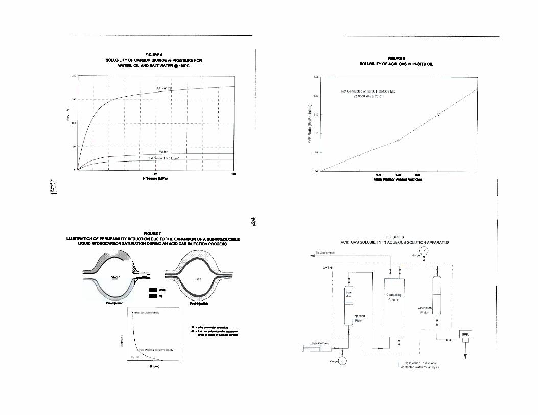
hydrocarbons, particularly light condensates, can be inexcess of 300 m3/m3). Solubility of pure CO2 in 40° API
gravity oil at 100°C is provided in Figure 5. Many
potential injection zones contain a residual mobile orimmobile liquid hydrocarbon saturation. This would includedepleted oil reservoirs, transition zones containing an
immobile oil saturation, waterflooded zones at a residual oil
saturation, depleted gas reservoirs containing an initialirreducible or sub-irreducible oil saturation, and depleted
retrograde condensate gas zones containing a trappedirreducible or sub-irreducible critical condensate saturation.Two potential concerns arise with respect to the contact ofthese hydrocarbon liquids with the acid gas as follows:
Solubility of acid gases in aqueous solution is a functionof the following parameters:
Acid gas composition
Contacting pressureContacting temperatureWater salinity
Compatibility - Many oils may de-asphalt when contactedwith diatomic gases such as CO2 and H2S. Theprecipitation of granular solid asphaltenes can lead toplugging of the pore system and restricted injectivity in thenear wellbore region. If injection into a zone containingliquid hydrocarbons is contemplated, detailed compatibilitytesting should be conducted between the live hydrocarbonliquid and the proposed injection gas over the range ofexpected downhole injection conditions to ensure thatdestabilization asphaltenes from the liquid hydrocarbonphase does not occur.
Solubility increases with increasing H2S concentrationand increasing pressure (although solubility generally levelsout near the critical pressure of the mixture (about 7000-10000 kPa). Solubility is reduced by increasing temperatureand increasing salinity of the contacted water. Figure 5provides an illustration of the solubility of pure carbondioxide in fresh and salt water at various pressures at100°C. There are virtually no published data on thesolubility of mixtures of acid in gases in water. Table 2provides a summary of some limited selected solubility dataavailable for different concentrations of acid gases atvarious temperature and pressure contacting conditions.Detailed experimental solubility studies should beconducted prior to any acid gas injection study. This willquantify the compatibility and expected solubility of thetarget acid gas stream in the specific aqueous phase presentin the reservoir or contemplated for co-injection.
Swelling - Due to the extreme solubility exhibited by rich
acid gases in most hydrocarbons a large formation volumefactor increase (expansion of the size of the liquidhydrocarbon phase) occurs when the acid gas contacts theinsitu oil. If pressure is sufficient, the acid gas may actuallybe miscible with the insitu crude which will result inmiscible displacement of the residual oil saturation awayfrom the wellbore area. potentially creating anadvantageous increase in relative permeability to theinjected acid gas and an increase in injectivity. In manysituations, the composition of the acid gas, liquidhydrocarbon gravity and downhole temperature andpressure conditions are not conducive to the establishmentof miscibility. In this situation, a portion of the injectiongas is absorbed into the trapped liquid hydrocarbon phase,
Problems may be associated with solubility of hydrogensulphide into water. Water solutions containing H2S are notstable and reaction with adsorbed oxygen can cause the
precipitation of elemental sulphur and turbidity. This mayresult in plugging of the injection zone by the suspendedsolid precipitate. The turbidity can be reduced by filtrationor stabilized with various inhibitors (ie. glycol), but both
techniques may increase the cost of the injection operation
5

POTENTIAL SIDE BENEFITScausing a large increase in forD1ation volume factor of dieoil. Figure 6 provides a pressure-composition diagram fora typical insitu retrograde condensate phase with amolecular weight of approximately 110 when contactedwidl a 500/0 H28/500/o CO2 acid gas stream at 10000 kPaand 60°C. It can be seen at the saturation point (ie. pointwhere die saturation pressure of the liquid is equivalent tothe injection pressure of 12000 kPa representing themaximum degree of swelling expected to occur) that anincrease in condensate volume of over 27% occurs due tosolubility effects.
Acid gas re-injection may have potential side benefits inaddition to the direct disposal of unwanted sour gas. Someof these factors have been alluded to previously, but willnow be discussed in greater detail. They include:
Potential Stimulative Nature Caused By CarbonateDissolution - In the absence of adverse precipitation effects
and dissolution induced fines mobilization and plugging,long-tenn acid injection may actually improve injectivity insome disposal wells due to low pH induced dissolutioneffects.If the expanded oil saturation is already at the irreducible
level, the problem may not be significant. When the oilsaturation expands, it is basically akin to increasing the oilsaturation, and the portion of the increased liquidhydrocarbon saturation in excess of the irreducible valueshould be mobilized and displaced deeper into theformation. Problems may occur if the original oil saturationis relatively small and is at a subirreducible level. Thisoften occurs in depleted gas condensate reservoirs or somegas reservoirs which have been created by gas migrationover geological time into previously oil bearing strata. Asthe liquid saturation increases in value, it still remainsbelow the irreducible value and hence is not mobilized, butexpands and occludes space previously available for gas tobe injected. The end result can be a significant reduction ingas phase injectivity if the configuration of the gas phaserelative permeability curve is very steep at low liquidsaturation values. Figure 7 provides an illustration of this
phenomena.
Desiccation - In most direct acid injection projects, the
injected acid gas will have been dehydrated to minimize
hydrate problems at surface. Due to higher downholetemperatures, hydrate formation will likely not be
problematic, but the dry nature of the injection gas mayresult in a gradual desiccation of a the trapped irreducibleor connate water saturation from the region adjacent to the
injection zone. This is analogous to a phenomenon whichoften occurs during injection of conventional dry gas into
gas storage reservoirs. The reduction in initial water
saturation can cause an increase in injectivity due to a
lessening of adverse relative penneability effects associatedwith the presence of the initial water saturation in theporous media. This effect may also be damaging if theinsitu water being desiccated is highly saturated with
soluble salts (for example, in a typical deep carbonate
fonnation). Desiccation of fluid by the injection gas results
in precipitation of these soluble salts within the pore systemwhich may have a counteracting effect on the expected
increase in permeability due to water saturation removal,depending on the location of the re-precipitation within the
pore system.
This problem is very difficult to diagnose without directfield or lab testing. Conventional gas-liquid relativepermeability curves can provide some insight, but theparameters and configuration of normal gas-liquid relativepermeability curves are generally significantly altered whenconsidering an acid gas-oil or acid gas-water system.Dissolution of the acid gas in the liquid phase significantlyreduces its viscosity (by an order of magnitude or more forsome hydrocarbon liquid systems) and also cansubstantially reduce interfacial tension between the gas and
liquid phases.
Limited Or Full Miscibility with In-situ Oil - Most acid gas
streams represent excellent miscible injection solvents(from a phase behaviour point of view) and very low orzero interfacial tension can be obtained with these gaseswith many oils at relatively low pressures. This makesthese gases potential EOR injectant candidates for themiscible displacement of oils (which are generally in andof themselves already sour). Due to the supercritical natureof the gas, actual volume available for injection is usuallytoo small to be an effective consideration for voidage
6
replacement for an EOR process. Situations do exist,however, where the rich acid gas, extracted from producedsolution gas from a large oil reservoir or directly from asour gas reservoir, could be used to miscibly inject intoadjacent smaller oil pools or isolated zones of the sourceoil pool. Detailed lab and numerical studies would berequired in this situation to confmn miscibility with theinsitu crude, pressure required to maintain low1FT/miscibility and potential compatibility concerns withthe gas-crude system and injectivity issues as discussedpreviously. Contingency plans for premature ultra-sour gasbreakthrough at a producing well are also a necessity inthis situation.
Phase Behaviour and Fluid-Fluid Compatibility
Water Solubility
Figure 8 provides a schematic of the apparatus used to
determine acid gas solubility in aqueous solutions. Becauseacid gases are preferentially soluble in aqueous solutionsover other natural gas components, a specialized continuous
contact procedure must be evaluated to ensure that the
maximum solubility number is evaluated, rather than
simply attempting to compress a given volume of wholeinjection fluid into a set volume of water.
The test procedure consists of dynamically contacting alarge volume of injection acid gas of the specifiedcompositions with water of the salinity proposed forinjection, or to be contacted in the injection interval. Thecontact test is conducted at either the surface contactingpressure and temperature (if scoping for an acid waterinjection scheme is contemplated), or at estimated averagebottomhole injection conditions that will occur in theinjection or disposal zone if a direct injection technique iscontemplated. This contacting generally occurs for severalhours/days by flow through the aqueous phase in acountercurrent fashion in a packed column assembly withsubsequent evaluation of the solubility of the resultingequilibrium saturated brine phase.
SCOPING PROCEDURES FOR THE DESIGN ANDIMPLEMENTATION OF AN ACID GAS INJECTIONPROJECT
This section of the paper discusses the specific testswhich should be conducted to quantify acceptability of anproposed injection or disposal zone for acid gas injection.The tests fall into three categories:
Phase behaviour/fluid-fluid compatibilityRock-injection fluid compatibilityReservoir containment and mobility
2.3.
Concerning Sour Acid Gas Laboratory StudiesOnce a saturated condition is achieved, the acid gas
saturated aqueous phase can be evaluated for:For any acid gas experimental procedure extreme safetyprecautions are required due to the corrosive and toxicnature of the gas. Hastelloy or Monel equipment is required
to obviate corrosion problems, and the tests should be
conducted in a sour rated isolation lab with floor level
suction, incineration of the produced gas stream from thelab, continuous H2S monitoring, remote camera sensing and
equipment operation, self-contained or umbilical breathingapparatus for test operators. All personnel should be fullytrained with respect to the handling of toxic and lethal H2S
gas.
. total acid gas solubilized (m3/m3)
. composition of the acid gas components which are
selectively absorbed. turbidity and compatibility. size and concentration of any destabilized precipitates. pH for dissolution, corrosion and scaling calculations
Hydrocarbon Solubility
If a sample of the liquid hydrocarbon phase which ispresent in the reservoir can be obtained, a multiple contactswelling test should be conducted on the hydrocarbonliquid to evaluate:
. degree of solubility of the acid gas in the hydrocarbon
phase at downhole temperature and pressure conditions
7

transitions or precipitation points which would not nolDlally
be apparent with conventional normal visual observations.New state-of-the-art acoustic resonance equipment is
currently being developed to assist in these measurementswhich will provide an new level of technology for
detecting difficult phase transitions associated with some of
these phenomena.
Rock-Fluid Interactions
A major concern in any acid gas or acid water injectionoperation is ensuring that we maintain sufficient injectivityto dispose of the volume of fluid required, and thisinjectivity is not compromised over a period of time byincompatibility issues. Reductions in injectivity will lead toincreased injection pressures which increase costs andsafety concerns at the surface. In addition, if injectionpressures are increased to fracture levels, containment ofthe acid gas or water in the zone of interest may becompromised with potentially disastrous results. Therefore,it is essential that proper design and evaluation of theefficacy of the injection operation into the zone of interestis evaluated prior to implementing the process. This isgenerally conducted through a series of laboratory coreflowtests using preserved or restored state core material fromthe zone of interest for injection.
. increase in oil fonnation volume factor (swelling) of
the liquid hydrocarbon phase caused by acid gasdissolution
. reduction in oil phase viscosity caused by acid gas
dissolution. degree of miscibility of the acid gas with the liquid
hydrocarbon and if, at reservoir temperature andpressure conditions, the two phases are first-contactmiscible (ie. a single phase mixture is always obtained,regardless of the ratio in which the two fluids aremixed), multiple contact miscible (miscibility isestablished further into the reservoir by the gradualvaporization the intermediates from the liquidhydrocarbon in the near wellbore region into the acidgas phase, causing it subsequent enrichment andeventual miscibility with the liquid hydrocarbons aftersufficient vaporization and enrichment occurs) orimmiscible.
. potential incompatibility between the acid gas phase
and the insitu liquid hydrocarbon. Rich acid gases candestabilize solid asphaltenes from many oils. Theprecipitation and subsequent deposition of these solidhigh molecular weight hydrocarbons in the nearinjection well region can reduce permeability andrestrict injectivity.
Figure 9 provides a schematic illustration of a typicalmultiple contact sensitivity apparatus used to determinethese parameters. The measurement of acid gas-liquidhydrocarbon interfacial tensions at downhole conditionsmay also be of interest to quantify the degree of miscibilityobtained. This apparatus is illustrated in Figure 10.
Figure 12 provides an illustration of a typical apparatusused for injectivity evaluation for an acid gas/waterinjection scheme. Core material, generally ftom the higherquality portion of the zone of interest (as this is where themajority of the injection will preferentially occur) is used.The tests are generally conducted on stacks of 3.8 cmdiameter plugs drilled from whole core so that the properhorizontal direction of flow (which is generally parallel tothe high perm bedding planes existing in many porousmedia) are duplicated. Sample lengths are typically 20-30cm to allow sufficient core for monitoring of dissolutionand reprecipitation effects if they occur.
Acid Gas Phase Behaviour and Stability
These tests are normally conducted to ensure that over
the range of conditions expected during the compressionand injection operation, the acid gas stream remains in a
single phase and the precipitation of elemental sulphur doesnot occur. Figure II provides a schematic of a typical
visual cell laser system used for these types of tests. Gas ofa specific composition is charged into the visual cell
system, and the pressure and temperature then varied overthe range of potential operating conditions. If phase
transitions or precipitation occurs, the optical refraction anddispersion characteristics of the acid gas phase are altered.
This can be detected with the laser to pinpoint phase
It is essential that the core material be at the correct
initial saturation and wettability conditions. Preserved core
(if such can be obtained with unaltered original saturations)is preferred but, in most cases, restored state core material
must be utilized due to a lack of available preserved statecore. If restored state core is used, documented wettabilityrestoration and saturation institution procedures should be
8

utilized. The core is azeotropically cleaned prior torestoration (to remove any residual salts or oxidizedhydrocarbons), and the correct initial oil and watersaturations are instituted and unifonnly dispersed in themedia, and appropriate aging time is allowed for wettabilityequilibria to be established. Offcut end sections of the coreplugs being tested are generally subjected to the pre-testthin section, scanning electron microscope and XRDanalysis to characterize the "pre-injection" unaltered rockmatrix. If a significant increase or decrease in injectivity isnoted, the use of post-test petrography on the actual post-injection stack can quantify the exact mechanism of thepermeability alteration through comparison with pre-test
analysis.
stimulation or reduction in penneability. In some cases, toevaluate extended contact of the acid gas/water, a shut-inperiod in a static mode of several days/weeks is usedmidway in the exposure period of the test.
Table 3 provides a normalized dataset for the results ofseveral direct acid gas injection experiments in sandstoneand carbonate (dolomite) formations. Some of these testswere conducted in the presence of irreducible condensatesaturations in the rock. Figure 13 provides a plot of thetransient permeability profiles for the acid gas injectionphases for the various tests.
In general, it can be seen that in most cases significant
problems with reduced injectivity were not apparent and inmany cases, slight increases in permeability were observed.These increases in permeability were mostly due to a
desiccation of a portion of the connate water saturation
from the injection zone by the large volume of desiccated
acid gas injected.
The core displacement tests are conducted at downhole
conditions of temperature, pore pressure and overburdenpressure so that the correct solubility and dissolution effects
of the acid gas contact on the matrix and insitu fluids are
duplicated.
In the cores which had condensate saturations, some
transient penneability reductions were observed due toexpansion of the condensate saturation, but it appears that
subsequent vaporization/displacement or pH induceddolomite dissolution counteracted this initial effect,negating the majority of the effect in the long-tenn. It isexpected in a lower penneability matrix that this damage
would be more severe.
Most tests are initiated with a reservoir condition baselinemeasurement of unimpaired injectivity. If an acid water
project is evaluated, penneability at full reservoirconditions to fonnation water is measured on the sample.
If an acid gas injection scheme is evaluated, penneability
to a non-reactive gas (generally humidified methane ornitrogen) is detennined to obtain the baseline injectivity. In
addition to providing the baseline penneability value, these
measurements also provide a good estimate of true insitu
penneability of the matrix in the proposed injection zonefor injectivity calculations. Obviously, if fractures or high
penneability laminations are present in the injection zone,
overall injectivity may be underestimated using thistechnique, but in general it provides a conservativeapproach to the evaluation of the potential injectivity of the
target zone.
For the two samples which exhibited significant damage,post-test petrography indicatedthat the plugging mechanism
was the migration of insoluble pyrobitumen flakes whichhad been apparently loosened by acid gas contact, possibly
by dissolution of carbonate based cements in the matrix bythe acid gas contact. This would possibly indicate somesensitivity of zones containing pyrobitumen to acid gasinjection, but the available dataset is too small to come toa definitive conclusion in this aspect.Sensitivity to the acid gas or water is then evaluated by
switching the injection fluid over to either the sour gas or
water stream and continuously injecting 100-500 PV of thisfluid through the sample over an extended (2-10 day)
period while continually tracking injectivity.ln most tests,once the injection has been completed, the displacementfluid is switched back to the non-reactive baseline fluid,and the penneability remeasured to obtain a final valuewith a fluid of rigidly known parameters to confinn a
In general, when reductions in permeability occurred the
majority of the change occurred in the first 10-20 PV of
injection, suggesting that in the field, rapid reductions in
injectivity could potentially occur if a situation ofincompatibility existed.
9

Reservoir Containment and Mobility 4 Gu, M.X., Li, Q.,Zbou, S. Y.,Chen, W.D. and Guo,T .M.: "Experimental and Modelling Studies on thePhase Behaviour of High H2S Content Natural GasMixtures", Fluid Phase Equilibria, 1993, Vol 82, 173-182.
Tests must be conducted to verify that the injected acidgas will be entirely contained in the injection/disposal zoneof interest. This nonnally involves documented proceduresto quantify the sealing capacity of the caprock above thezone (vertical fluid penneability of less than lO~ mD anda threshold entry pressure for gas in excess of 7000 kPa).Detailed geological studies may also be required to ensurethat natural fractures or high penneability laminae will notresult in the rapid migration of the acid gas/water out of orto undesired locations in the injection/disposal zone.
s Tuttle, R.N., "What is a Sour Environment?", Journalof Petroleum Technology, March, 1990, pp 260-262.
Stair, M.A., McInturff, T .L., "Casing and TubingDesign Considerations for Deep Sour Gas Wells",IADC/SPE 11392, Presented at the IADC/SPE 1983Drilling Conference, New Orlean, LA, February 20-23,1983.
6.
CONCLUSIONS
Acid gas or water injection has proven to be a viabletechnology for the disposal of large volumes of waste acidgas. Detailed studies need to be undertaken to quantify theproper process and location of the injection/disposal zoneand to minimize risk due to poor containment of the acidgas or impaired injectivity. Potential concerns with fluidphase behaviour, solubility and compatibility with theinjection zone matrix can be evaluated in the laboratory tooptimize the acid gas injection process and reduce operatorrisk.
Mussumeci, A., "Computation in Gas HydrateFonnation", SPE 21112, Presented at the SPE LatinAmerica Petroleum Engineering Conference, Rio deJaneiro, October 14-19, 1990.
Yousif, M.H. and Sloan. E.D., "ExperimentalInvestigation of Hydrate Fonnation and Dissociation inConsolidated Porous Media", SPE 20172, UnsolicitedManuscript Dated October 19, 1989.
8.
Rossi. L.F .S., Gasparetto, C.A.,"Prediction of HydrateFonnation in Natural Gas Systems", SPE 22715,Presented at the 66th Annual Technical Meeting,Dallas, Texas, October 6-9, 1991.
9ACKNOWLEDGEMENTS
The authors express appreciation to Maggie Irwin andVivian Whiting for their assistance in the preparation of themanuscript and figures. 10. Hubbard, RA., "Recent Developments in Gas
Dehydration and Hydrate Inhibition", SPE 21507,Presented at the SPE Gas Technology Symposium,Houston, Texas, January 23-25, 1991.
REFERENCES
"Natural Gas Processors Association Handbook", 1980,Gas Processing Suppliers Organization, Tulsa. OK. 11. lseux,J.C., "Gas Hydrates: Occurrence, Production and
Economics", SPE 21682, Presented at the ProductionsOperations Symposium, Oklahoma City, OK, April 7-9, 1991.
"Merck Chemical Index", 10th Edition, Merck & CoInc., Rahway, N.J., USA, 1983.
2
Mohsen-Nia. Mohsen. Moddaress, Hamid. Arnir-Kabir,U. and Mansoori, G.A., "Sour Natural Gas and LiquidEquation of State", SPE 26906, Presented at the 1993
Eastern Regional Conference and Exhibition, Pittsburg,
PA, 1993.
12. Hammerschmidt, E.G., "Fonnation of Gas Hydrates inNatural Gas Transmission Lines", Ind Eng Chem, 26,851, 1934.
3
13. Dodds, W.S. et al: "CO2 Solubility in Water", ChernEng Data Series 1, 1956, pg 92.
10
14. Munjal, P. and P.B. Stuwart: "Solubility of CarbonDioxide in Pure Water, Synthetic Sea Water andSynthetic Sea Water Concentrates at -5°C to 25°C and10 to 45 A TM Pressure It, Journal of ChemicalEngineeringData, 1970, 15:67.
15. Simon, R. and D. Graue: "Generalized Correlationsfor Predicting Solubility, Swel1ing and ViscosityBehaviour of CO2 - Crude Oil Systems", J. Pet. Tech.,
Jan. 1965, pg. 102.
1
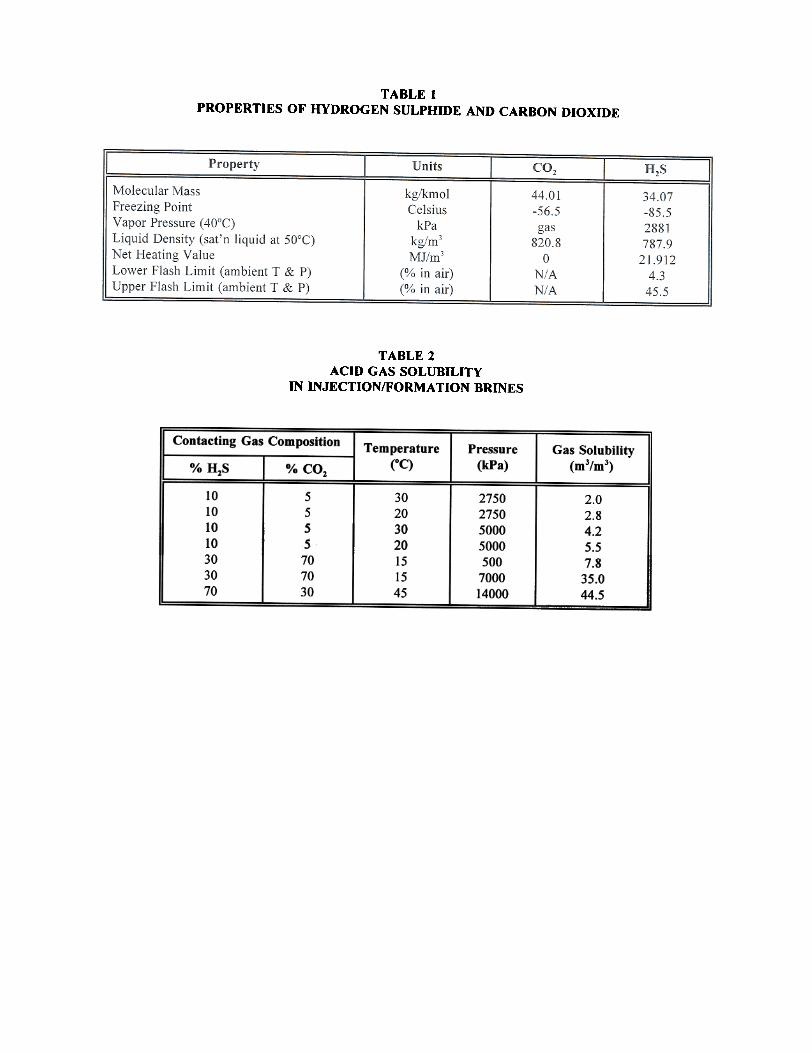
TABLE IPROPERTIES OF HYDROGEN SULPHIDE AND CARBON DIOXIDE
TABLE 2ACm GAS SOLUBILITY
IN INJECTION/FORMA TION BRINES
Contacting Gas CompositionPressure
(kPa)Temperature
(OC)Gas Solubility
(m3/m3)0;0 H1S 0;0 CO2
10101010303070
sssS707030
30203020151545
2750275050005000500
700014000
2.02.84.25.57.8
35.044.5

TABLE 3NORMALIZED INJECfMTY RATIOS FOR POROUS MEDIA
ACm GAS INJECTION TESTS(Tests conducted at representative reservoir temperatures ranging from 40-80oC
using acid gases containing 30-65% HzS)
Injectivity Ratio(Perm/Initial Perm)
Pore Volumes ofAcid Gas Injected
(Cuml) T#2 1'#3 T#4 T#5T#1 T#6
O.S1.0I.S2.04.06.08.0
10.0IS.020.030.0SO.O
100.0
1.002.002.923.424.084.424.674.755.425.835.926.006.00
1.001.070.930.940.650.540.450.420.400.370.370.310.35
1.000.970.930.870.730.720.680.650.660.610.450.360.36
1.001.000.970.960.940.890.900.880.8S0.900.941.021.04
1.000.750.650.560.760.870.961.041.091.071.040.%1.00
1.001.020.980.940.981.060.980.961.091.001.001.001,04
Legend
Test 1 - Sandstone sample containing pyrobitumen, moderate pefDleability at initial Swi with no oil saturation,pefDleability reduction believed to be due to dissolution of carbonate cements and mobilization and plugging bypyrobitumen fines.
Test 2 - Sandstone sample, moderate permeability, simulating an oil saturated zone. Permeability to gas increasesrapidly as oil is miscibly displaced from the sample by the low IFf acid injection gas.
Test 3 - Very low perD1eability intercrystalline carbonate at initial water saturation with no oil present. Dissolutionand plugging effects were caused gradually by acid gas injection.
Tesl4 - Carbonate, moderate permeability, initial water saturation present, oscillations in penneability indicate somepotential dissolution and migration effects, final slight stimulation likely due to desiccation of the initial watersaturation caused by long-tenD acid gas injection.
Test 5 - Carbonate, moderate permeability, contained initial water and irreducible retrograde condensate saturation.Transient reduction in permeability at low PV of gas injected believed to be due to expansion and subsequentmobilization of the portion of the trapped condensate saturation.
Test 6 - Sandstone, moderate penneability, initial water saturation with no oil present, slight stimulative effect maybe due to desiccation effects caused by long-tenD acid gas injection.

~~.u
I!00.
:~W
)2~~
Qi
~i~~
rL5~~
~i
oJ
0I~.~Ie~
~~~I
{a 5I
~ 5'I~II:1~
~
~~~
Ii~Ii ,.
~~f
"~i
~~
~m
l5
u: z
~~
~i
~
i~~
C;)
l~ -
::I -I ~II
i'i l.
III ~
I
tlI££~lIE.
...
I~

~~
la~~
I~
g ,
i~
'
~~
~I
Iii:~I 'i~
iI~
:
,W!
I,--
i--~
i~
f~:
s~
~ .
I
;ii :
~~
-~
~~ ~§
-
;~ ; rIIJ
J~
Iti!
--
J
I'[
~_-
I ,
: ~.~
II
JJ~
IJ
~
IIII
~
:
I i
~
:..1
:~
w
Iil
:
~§
:
I i
i :
~I
I~~!
~i.
~I
-II.)-~IIIIi~Q
.
II
~~
-IIIIi~
i
fjJ--JI
~I,,

~I
~~=~~
i~~~io
-i
Iii
jti t i+iti~i~
~
~-~
.
'I.I'5
J
I
~~