Embed Size (px)
Citation preview
This is a repository copy of Formation of white etching cracks at manganese sulfide (MnS)inclusions in bearing steel due to hammering impact loading.
White Rose Research Online URL for this paper:http://eprints.whiterose.ac.uk/98592/
Version: Accepted Version
Article:
Bruce, T., Long, H. orcid.org/0000-0003-1673-1193, Slatter, T. orcid.org/0000-0002-0485-4615 et al. (1 more author) (2016) Formation of white etching cracks at manganese sulfide (MnS) inclusions in bearing steel due to hammering impact loading. Wind Energy, 19 (10). pp. 1903-1915. ISSN 1095-4244
https://doi.org/10.1002/we.1958
This is the peer reviewed version of the following article: Bruce, T., Long, H., Slatter, T., and Dwyer-Joyce, R. S. (2016) Formation of white etching cracks at manganese sulfide (MnS) inclusions in bearing steel due to hammering impact loading. Wind Energ., doi: 10.1002/we.1958., which has been published in final form at http://dx.doi.org/10.1002/we.1958. This article may be used for non-commercial purposes in accordance with Wiley Terms and Conditions for Self-Archiving (http://olabout.wiley.com/WileyCDA/Section/id-820227.html).
[email protected]://eprints.whiterose.ac.uk/
Reuse
Unless indicated otherwise, fulltext items are protected by copyright with all rights reserved. The copyright exception in section 29 of the Copyright, Designs and Patents Act 1988 allows the making of a single copy solely for the purpose of non-commercial research or private study within the limits of fair dealing. The publisher or other rights-holder may allow further reproduction and re-use of this version - refer to the White Rose Research Online record for this item. Where records identify the publisher as the copyright holder, users can verify any specific terms of use on the publisher’s website.
Takedown
If you consider content in White Rose Research Online to be in breach of UK law, please notify us by emailing [email protected] including the URL of the record and the reason for the withdrawal request.
Formation of white etching cracks at manganese sulphide (MnS)
inclusions in bearing steel due to hammering impact loading
T. Bruce, H. Long*, T. Slatter, R. S. Dwyer-Joyce
Department of Mechanical Engineering, The University of Sheffield, United Kingdom
Tel: +44 (0) 114 222 7759
Fax: +44 (0) 114 222 7890
Wind turbine gearbox bearings (WTGBs) are failing prematurely, leading to increased
operational costs of wind energy. Bearing failure by white structure flaking (WSF) and axial
cracking may both be caused by the propagation of white etching cracks (WECs) and have been
observed to cause premature failures, however their damage mechanism is currently not well
understood. Crack initiation has been found to occur at subsurface material defects in bearing
steel, which may develop into WECs. One hypothesis for WEC formation at these defects, such
as non-metallic inclusions, is that repetitive impact loading of a rolling element on a bearing
raceway, due to torque reversals and transient loading during operation, leads to high numbers
of stress concentrating load cycles at defects that exceed the material yield strength.
In this study, a number of tests were carried out using a reciprocating hammer type impact rig.
Tests were designed to induce subsurface yielding at stress concentrating manganese sulphide
(MnS) inclusions. The effects of increasing surface contact stress and number of impact cycles,
with and without surface traction, were investigated. Damage adjacent to MnS inclusions,
similar to that observed in a failed WTGB raceway was recreated on bearing steel test
specimens. It has been found that increasing the subsurface equivalent stresses and the number
of impact cycles both led to increased damage levels. Damage was observed at subsurface
equivalent stresses of above 2.48 GPa after at least 50,000 impact cycles. WECs were recreated
during tests that applied surface traction for 1,000,000 impacts.
Keywords
Wind turbine gearbox, hammering impact loading, overload, bearing failure, white etching crack,
white etching area, manganese sulphide (MnS) inclusion.

1. Introduction
During the past 15 to 20 years the wind energy industry has rapidly expanded, a trend that will
continue throughout this decade. The European Wind Energy Agency (EWEA) has a planned target of
230 GW of installed wind power capacity by 2020, representing 20% of total EU electricity
consumption [1]. This expansion is being limited by the high operating cost of wind energy, which is
made more expensive by a number of maintenance issues, most critically concerning wind turbine
gearboxes (WTGs) which are not reaching their anticipated lifespan of 20 years. It is estimated that
operation and maintenance (O&M) account for 20% of the cost of offshore wind energy in the EU [2,
3].
The majority of WTG failures initiate in the wind turbine gearbox bearings (WTGBs) [4], and the
exact modes of their failure are currently not well understood despite intensive research effort. This
study will investigate a mode of failure that is commonly found within failed WTGBs named white
etching cracking, which is described in more detail in the following section. A reciprocating hammer
type impact test rig was used to initiate subsurface cracks at MnS inclusions and under certain
conditions, created white etching cracks (WECs) at the inclusions. Different factors that may affect
the probability of MnS inclusion initiated damage were investigated, namely: number of impact
cycles, subsurface equivalent stress level and surface traction by introducing simultaneous sliding
and impact loading, termed as compound impact in this study.
1.1. White etching cracks
Currently, the mechanism by which WECs lead to WTGB failure is not fully understood, and hence
there is no method of calculating remaining useful bearing life due to the failure in WTG applications
[5, 6, 7, 8]く さWエキデW WデIエキミェざ ヴWaWヴゲ デラ デエe colour of the altered steel microstructure, after having
been etched in nitric acid/ethanol solution (nital) [9]. WECs may form irregular crack networks,
named "irregular white etching areas" (IrWEAs) and follow pre-austenite grain boundaries [6]. These
crack networks form up to the depth of maximum shear stress, occurring over large subsurface areas
and eventually leading to failure by flaking of material from the surface, also known as white
structure flaking (WSF). IrWEAs have been observed to propagate radially from straight-growing
cracks that are parallel to the surface in the axial direction. Through-hardened bearings are prone to
fail via the axial cracking mode, whereas carburised bearings with less than 20% retained austenite
fail by WSF [6]. If this WEA weakens the near-surface of the raceway sufficiently, failure occurs via
spalling. White etching cracking leading to WSF is a mode of damage that can lead to bearing failure
within 1-20% of the L10 design life [3] predicted by current bearing design standards [10].
Under high loading, stress concentration around material defects may result in yielding of the
bearing steel. As a result, crack initiation may occur at the location of maximum equivalent stress
around the stress concentrating material defect. Surface traction caused by the overrolling of a
rolling element shifts the position of these subsurface stress concentrations around material defects.
Finite element analysis software Abaqus was used to illustrate stress concentration around an
arbitrarily sized material defect (in this case a circular void as an example). The positions of
maximum equivalent stress around the void under compressive load are shown in Figure 1a. Figure
1b shows how the introduction of surface traction shifts this stress field around the void, and as a
result, the positions of maximum subsurface equivalent stress in the material subsurface.
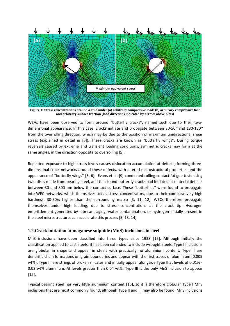
Figure 1: Stress concentrations around a void under (a) arbitrary compressive load: (b) arbitrary compressive load and arbitrary surface traction (load directions indicated by arrows above plots)
WEAゲ エ;┗W HWWミ ラHゲWヴ┗WS デラ aラヴマ ;ヴラ┌ミS さH┌デデWヴaノ┞ Iヴ;Iニゲざが ミ;マWS ゲ┌Iエ S┌W デラ デエWキヴ デ┘ラ-
dimensional appearance. In this case, cracks initiate and propagate between 30-50° and 130-150°
from the overrolling direction, which may be due to the position of maximum unidirectional shear
stress (explained in detail in [5]). These cracks ;ヴW ニミラ┘ミ ;ゲ さH┌デデWヴaノ┞ ┘キミェゲざく During torque
reversals caused by extreme and transient loading conditions, symmetric cracks may form at the
same angles, in the direction opposite to overrolling [5].
Repeated exposure to high stress levels causes dislocation accumulation at defects, forming three-
dimensional crack networks around these defects, with altered microstructural properties and the
;ヮヮW;ヴ;ミIW ラa さH┌デデWヴaノ┞ ┘キミェゲざ [5, 6]. Evans et al. [9] conducted rolling contact fatigue tests using
twin discs made from bearing steel, and that found butterfly cracks had initiated at material defects
between 30 and 800 µm below the contact surface. TエWゲW さH┌デデWヴaノキWゲざ ┘Wヴe found to propagate
into WEC networks, which themselves act as stress concentrators, due to their comparatively high
hardness, 30-50% higher than the surrounding matrix [3, 11, 12]. WECs therefore propagate
themselves under high loading, due to stress concentrations at the crack tip. Hydrogen
embrittlement generated by lubricant aging, water contamination, or hydrogen initially present in
the steel microstructure, can accelerate this process [5, 13, 14].
1.2.Crack initiation at maganese sulphide (MnS) inclusions in steel
MnS inclusions have been classified into three types since 1938 [15]. Although initially the
classification applied to cast steels, it has been extended to include wrought steels. Type I inclusions
are globular in shape and appear in steels with practically no aluminium content. Type II are
dendritic chain formations on grain boundaries and appear with the first traces of aluminium (0.005
wt%). Type III are strings of broken silicates and initially appear alongside Type II at levels of 0.01% -
0.03 wt% aluminium. At levels greater than 0.04 wt%, Type III is the only MnS inclusion to appear
[15].
Typical bearing steel has very little aluminium content [16], so it is therefore globular Type I MnS
inclusions that are most commonly found, although Type II and III may also be found. MnS inclusions
(a) (b)
Maximum equivalent stress

in hot-rolled steels are randomly distributed and of irregular shape. During manufacture, the MnS
inclusions are flattened and elongated in the direction of rolling [15]. All inclusions may act as crack
initiation sites under high enough contact stress [17], however in the case of white structure flaking
in WTGBs, MnS inclusions have been found to be the most likely to interact with white etching crack
(WEC) damage [18]. It has been found that shorter inclusions are more likely to initiate damage than
longer inclusions, with the ideal length for crack propagation found to be smaller than 20 ´マ (based
on a sample size of 76 WEC-interacting inclusions) [18]. During quenching of bearing steel, the
different thermal contraction rates of the bulk material and MnS inclusions may weaken the bond
between the inclusion and the surrounding bulk material [9], or possibly lead to the creation of free
surface at the inclusion/steel boundary [17]. These free surfaces are potential sites for inclusion
separation from the bulk material and for initiating cracking under cyclic loading [17].
Although weakly bonded inclusions and free surfaces may be potential crack initiation sites, it is not
necessary for a MnS inclusion to initiate a crack because of the poor bond with the bulk material. A
thin, flattened MnS inclusion may itself act as a virtual crack [19] that may propagate into an actual
crack. In rail steel, MnS inclusions can become significant crack initiators [20]. It was found that near
to the rail surface, all MnS inclusions were deformed first in the material displaced direction, moved
to the shear angle caused by over-rolling, and then flattened as they reached the wear surface. Wear
tests on four rail steel types confirmed that almost all deformed MnS inclusions near to the wear
surface were associated with cracks [19].
MnS inclusions became elongated under load because they deform more than the surrounding
matrix [21, 22]. Cracks can be initiated along the highly deformed flattened MnS inclusions [21], due
to: (1) micro-crack initiation at localised deformation bands in the vicinity of the inclusions; (2) high
stress concentration in the middle of the elongated inclusions leading to interfacial debonding and
void formation, which are potential crack initiation sites; (3) break up the inclusions because of its
lower plastic limit, causing the cracks to form within the inclusion [22], which may propagate into
the bulk material [18]; or (4) by high stress concentration at the lowest radius of curvature inclusion
tips that coincide with the position of maximum subsurface equivalent stress as shown in Figure 1.
It has been found that one method of WEC initiation at MnS inclusions is by the propagation of
cracks that are initiated within the inclusion, and spread into the surrounding material [11, 18].
WECs may then develop along the cracks [11]. It has been found by the authors, in a related study
[23], that it is not necessarily the case that they must be cracked along their major axis in order to
form a WEA as shown in Figure 2f, but may also form at cracks caused by other factors previously
discussed. This process is illustrated in Figure 2, which shows optical microscopy and SEM images
taken of MnS inclusions from a failed WTGB provided for destructive investigation [23], in which
WEC initiating MnS inclusions were found at depths of up to around 600 µm from the raceway
surface. In this study, the vast majority of inclusion initiated damage, and all inclusion initiated WEC
damage, was caused at MnS-type inclusions. Such damage was observed when viewing inclusions
sectioned through the bearing axial and circumferential directions. Crack initiation around MnS
inclusions and short crack growth can be explained by Mode I loading (normal to crack growth
direction). Further growth of the cracks governed by Mode II/III shear loading (in-plane shear/off-
plane shear) [9, 23, 24]. Shear loading increases in bearings under the influence of surface traction,
caused by skidding of the rollers on the raceway surface [5]. It is possible that WECs require a certain
level of surface traction in order to form.

Figure 2: Crack development at MnS inclusions from a failed WTGB a) Cracked along length of inclusion b) Crack propagated into bulk material c) & d) Split inclusion with crack propagating into bulk material e) WEA developing at split MnS inclusion e) WEA developing at MnS inclusion with no split (adapted from [23]). Images (a) and (f) are
from axially sectioned specimens (over-rolling direction into the page), images (b)-(e) are from circumferentially sectioned specimens (over-rolling direction left to right).
1.3.Hammering impact hypothesis
The transient nature of the wind and operational loading of a WT creates extremely harsh operating
conditions for drivetrain components leading to subsurface material plastic deformation [3, 11]. The
high variability of wind conditions and subsequent turbine controls leads to frequent connections
and disconnections between the generator and grid, causing the gearbox to experience frequent
torque reversals and overloads [25]. Such torque reversals can occur approximately 15,000 times
per year [25], and in extreme cases, contact stress levels may exceed 3.1 GPa [11], well above the
yield strength of bearing steels [17]. Maximum recommended contact pressures from the wind
turbine design standard [26] are regularly exceeded, even during normal operating conditions [27].
A number of studies have been carried out using test rigs to recreate butterflies and/or WECs in
bearing steel. Both Lund [28] and Grabulov [29] successfully recreated butterflies finding that a
contact stress threshold must be exceeded for their initiation. Evans et al. [30] recreated WECs on
hydrogen charged specimens under rolling contact fatigue at contact pressures between 1.2-2.0
GPa. Further work from Evans [18] created WECs in a tested WTGB under transient conditions with
maximum contact pressures of 2.15 GPa.
ヲヰ ´マ
ヲヰ ´マ
a b
c
ヲヰ ´マ
e
d
f
Crack propagated
into bulk material
Inclusion cracked
along length
Inclusion cracked
along length
Inclusion cracked
along length
Crack propagated
into bulk material
Inclusion cracked
along length
Crack propagated into
bulk material
WEA developed on
cracks
Inclusion cracked
along length
WEA developed from
end of inclusion
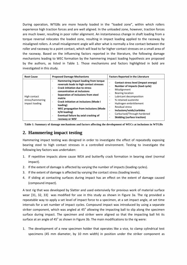
D┌ヴキミェ ラヮWヴ;デキラミが WTGBゲ ;ヴW マラヴW エW;┗キノ┞ ノラ;SWS キミ デエW さノラ;SWS ┣ラミWざが ┘キデエキミ ┘エキIエ ヴラノノWヴゲ experience high traction forces and are well aligned. In the unloaded zone, however, traction forces
are much lower, resulting in poor roller alignment. An instantaneous change in shaft loading from a
torque reversal relocates the loaded zone, resulting in impact loading applied to the raceway by
misaligned rollers. A small misalignment angle will alter what is normally a line contact between the
roller and raceway to a point contact, which will lead to far higher contact stresses on a small area of
the raceway. Based on the influencing factors reported in the literature, the following damage
mechanisms leading to WEC formation by the hammering impact loading hypothesis are proposed
by the authors, as listed in Table 1. Those mechanisms and factors highlighted in bold are
investigated in this study.
Root Cause Proposed Damage Mechanisms Factors Reported in the Literature
High contact
stress/hammering
impact loading
- Hammering impact loading from torque
reversals leads to high contact stresses
- Crack initiation due to stress
concentration at inclusions
- Separation of inclusions from steel
matrix
- Crack initiation at inclusions (Mode I
loading)
- WEC propagation from inclusions (Mode
II/III loading)
- Eventual failure by axial cracking of
raceway or WSF
- Contact stress level (impact energy)
- Number of impacts (load cycle)
- Misalignment
- Bearing location
- Lubricant decomposition
- % retained austenite
- Hydrogen embrittlement
- Residual stress
- Inclusions/voids/carbides
- Carburised/Through-hardened
- Skidding (surface traction)
Table 1: Summary of damage mechanisms and factors affecting the development of WECs at inclusions in WTGBs
2. Hammering impact testing
Hammering impact testing was designed in order to investigate the effect of repeatedly exposing
bearing steel to high contact stresses in a controlled environment. Testing to investigate the
following key factors was undertaken:
1. If repetitive impacts alone cause WEA and butterfly crack formation in bearing steel (normal
impact).
2. If the extent of damage is affected by varying the number of impacts (loading cycles).
3. If the extent of damage is affected by varying the contact stress (loading levels).
4. If sliding at contacting surfaces during impact has an effect on the extent of damage caused
(compound impact).
A test rig that was developed by Slatter and used extensively for previous work of material surface
wear [31, 32, 33] was modified for use in this study as shown in Figure 3a. The rig provided a
repeatable way to apply a set level of impact force to a specimen, at a set impact angle, at set time
intervals for a set number of impact cycles. Compound impact was introduced by using a separate
striker component, which was angled at 45o allowing the impacting ball to slip along the specimen
surface during impact. The specimen and striker were aligned so that the impacting ball hit its
surface at an angle of 45o as shown in Figure 3b. The main modifications to the rig were:
1. The development of a new specimen holder that operates like a vice, to clamp cylindrical test
specimens (45 mm diameter, by 10 mm width) in position under the striker component as

shown in Figure 3. Note that the position of the specimen is such that the impacting ball hits the
specimen normal to its surface.
2. TエW ;デデ;IエマWミデ ラa デエW さマ;ゲゲ エラノSWヴざ ヮノ;デW ラミデラ デエW さヮキ┗ラデ HノラIニざが ;ノノラ┘キミェ aラヴ Iラ┌ミデWヴ┘Wキェエデゲ to be attached to the arm, altering the WaaWIデキ┗W マ;ゲゲ ラa デエW さゲデヴキニWヴざ in order to vary the impact
load levels.
Figure 3: Modified impact test rig a) normal impact b) compound impact
2.1.Tested specimens
Through-hardened 100CrMo7 bearing steel specimens were tested using the hammering impact rig.
Before testing, the specimens were quenched then tempered at 260 °C, to achieve a hardness of
around 60 HRC. The surface was ground to give a maximum roughness, Ra, of 1 micron. The material
was selected for its yield strength and hardness properties, which were suited to the capabilities of
the test rig so that subsurface damage could be caused, without significant surface damage. The
steel balls used to impact the specimens were slightly harder than the specimens, so that damage
was first experienced on the specimens. The approximate chemical composition of non-FE elements
found in the specimens is shown in Table 2 [34] and the mechanical properties of both the
specimens [17] and the impact steel ball, in Table 3.
C% Si% Mn% S% Cr% Ni % Mo%
0.99 0.30 0.70 0.015 1.80 0.13 0.25
Table 2: Chemical composition of specimens used during testing
100CrMo7 (specimen) 100Cr6 (impact ball) Young’s modulus 210 GPa 210 GPa
Hardness 59-61 HRC 60-67 HRC[33] Yield strength 1.7 GPa ~2 GPa
Tensile strength 2.4 GPa ~2.3GPa Poisson’s ratio 0.3 0.3
Density 7800 kg/m3 ~7800 kg/m3 Diameter 45 mm 15 mm
Surface roughness, Ra (max) 1 たm 0.125 たm [33]
Table 3: Mechanical properties of specimens [17] and impact steel balls used during testing (Approximate 100Cr6 properties from [17])
Direction
of impact
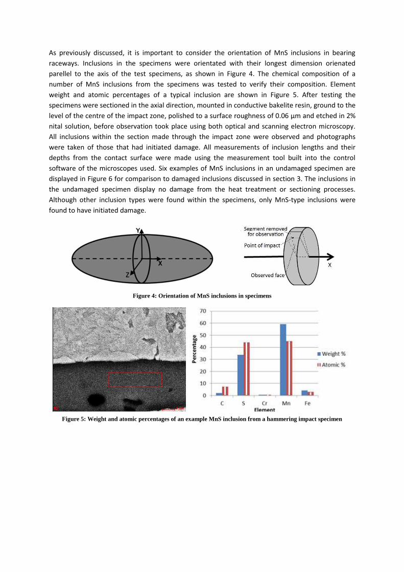
As previously discussed, it is important to consider the orientation of MnS inclusions in bearing
raceways. Inclusions in the specimens were orientated with their longest dimension orienated
parellel to the axis of the test specimens, as shown in Figure 4. The chemical composition of a
number of MnS inclusions from the specimens was tested to verify their composition. Element
weight and atomic percentages of a typical inclusion are shown in Figure 5. After testing the
specimens were sectioned in the axial direction, mounted in conductive bakelite resin, ground to the
level of the centre of the impact zone, polished to a surface roughness of 0.06 ´マ and etched in 2%
nital solution, before observation took place using both optical and scanning electron microscopy.
All inclusions within the section made through the impact zone were observed and photographs
were taken of those that had initiated damage. All measurements of inclusion lengths and their
depths from the contact surface were made using the measurement tool built into the control
software of the microscopes used. Six examples of MnS inclusions in an undamaged specimen are
displayed in Figure 6 for comparison to damaged inclusions discussed in section 3. The inclusions in
the undamaged specimen display no damage from the heat treatment or sectioning processes.
Although other inclusion types were found within the specimens, only MnS-type inclusions were
found to have initiated damage.
Figure 4: Orientation of MnS inclusions in specimens
Figure 5: Weight and atomic percentages of an example MnS inclusion from a hammering impact specimen

Figure 6: Typical MnS inclusions in undamaged specimen
2.2.Test design using finite element analysis
As shown in Figure 2, one form of WEC damage can initiate at defects below the raceway surface.
Therefore, it seems logical to design experiments that create subsurface plastic deformation, but do
not exceed the material yield strength on the surface. Commercial software Abaqus was used in
Finite Element Analysis (FEA) to simulate the impact between the steel ball and specimen. Explicit
analysis was used to model the contact stresses caused by the impact of a correctly dimensioned
steel ball, with the effective mass of the striker, upon a specimen. The steel ball was given velocity
equal to the velocity of impact for each test condition and the resulting contact pressures during
impact were calculated by the dynamic FEA model. The material properties listed in Table 3 along
with its stress-strain behaviour, were used to define the material. The stress-strain curve found from
a tensile test of through hardened 100Cr6 bearing steel (also tempered at 260 °C) was used [35],
which has very similar stress-strain behaviour to 100CrMo7 bearing steel [34]. Compressive stress-
strain data was not available and although tensile behaviour cannot accurately model compressive
HWエ;┗キラ┌ヴ IノラゲW デラ デエW マ;デWヴキ;ノげゲ ┌ノデキマ;デW ゲデヴWミェデエが キデ エ;ゲ HWWミ ;ゲゲ┌マWS デエ;デ デエW ヴWゲ┌ノデゲ ;ヴW accurate enough to approximate the surface contact stress, which is below the yield strength of the
material for all tests and is the key result from FEA simulations. Maximum stress levels on the
surface and subsurface were recorded from the equivalent stress (von Mises) distribution calculated
using FEA.
Contact was modelled using さエ;ヴSざ Iラミデ;Iデ with default constraint enforcement; normal behaviour
and tangential behaviour was assumed to frictionless. Surfaces were assumed to be smooth. Since
contact between the two bodies is symmetrical around the centre of contact when sectioned axially
(along the specimen axis) and circumferentially (through the circumference of the specimen),
modelling a quarter of the lower half of the impacting ball and upper half of the specimen provided
a computationally efficient way of obtaining results. Consequently, the effective mass of the ball was
divided by four, since only a quarter of the contact area was available to absorb the impact energy.
Since the model was designed to simulate symmetric contact about the centre of impact, it could
not be used to accurate simulate sliding contact, which effectively has a moving point of impact. For
this reason the simple assumption was made that the contact pressures were equal to that of a
normal impact with an impact velocity equal to the radial velocity component of the sliding impact,
defined using equation 4.3. From this, the contact pressure could be found using the normal impact
FEA model. U嘆叩辰辿叩狸 噺 濁棟嶋套凍套投塔ヂ態 (1)
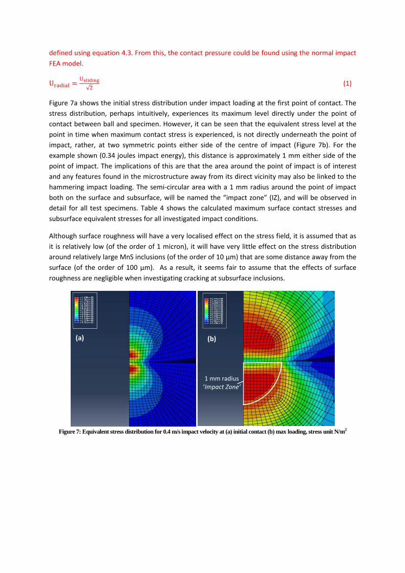
Figure 7a shows the initial stress distribution under impact loading at the first point of contact. The
stress distribution, perhaps intuitively, experiences its maximum level directly under the point of
contact between ball and specimen. However, it can be seen that the equivalent stress level at the
point in time when maximum contact stress is experienced, is not directly underneath the point of
impact, rather, at two symmetric points either side of the centre of impact (Figure 7b). For the
example shown (0.34 joules impact energy), this distance is approximately 1 mm either side of the
point of impact. The implications of this are that the area around the point of impact is of interest
and any features found in the microstructure away from its direct vicinity may also be linked to the
hammering impact loading. The semi-circular area with a 1 mm radius around the point of impact
both on the surface and subsurface, will be named the さimpact zoneざ (IZ), and will be observed in
detail for all test specimens. Table 4 shows the calculated maximum surface contact stresses and
subsurface equivalent stresses for all investigated impact conditions.
Although surface roughness will have a very localised effect on the stress field, it is assumed that as
it is relatively low (of the order of 1 micron), it will have very little effect on the stress distribution
around relatively large MnS inclusions (of the order of 10 ´マ) that are some distance away from the
surface (of the order of 100 ´マ). As a result, it seems fair to assume that the effects of surface
roughness are negligible when investigating cracking at subsurface inclusions.
Figure 7: Equivalent stress distribution for 0.4 m/s impact velocity at (a) initial contact (b) max loading, stress unit N/m2
(a) (b)
1 mm radius
けImpact Zoneげ

3. Test results and discussion
Hammering impact tests described by Table 4 were designed in order to investigate the above stated
factors. After testing, surface inspection of the IZ revealed that there was almost no visible surface
S;マ;ェW ラミ ;ミ┞ ラa デエW ゲヮWIキマWミゲが ;ノデエラ┌ェエ ; ゲマ;ノノ さゲマララデエWSざ マ;ヴニ ┘;ゲ ノWaデ ┘エWヴW デエW ゲ┌ヴa;IW oxide layer had been removed. This mark was useful to determine the exact point of impact, which
was carefully marked before sectioning. It is unclear whether this small mark was caused by very low
levels of plastic deformation of the surface or the removal of an oxide layer. However, as bearing
contact stress in wind turbines sometimes exceeds bearing steel yield strength by significantly higher
percentages than those experienced during these tests, surface plastic deformation may also occur
in WTGBs. As damage was found as deep as 300 ´マ below the contact surface, it is assumed that
damage at inclusions is not affected by this small mark.
Specimen
number
Impact
frequency
(Hz)
Impact
velocity
(m/s)
Surface
stress
max (GPa)
Subsurface
stress max
(GPa)
Striker
angle
(degrees)
Test
time
(mins)
Number
of cycles
Init
ial
test
ing
1 10 0.45 1.675 2.580 90 166.7 100,000
2 10 0.45 1.675 2.580 90 166.7 100,000
3 10 0.45 1.675 2.580 90 166.7 100,000
TE
ST
1:
Va
ryin
g
nu
mb
er
of
imp
act
s
4 11 0.50 1.687 2.603 90 303.0 200,000
5 11 0.50 1.687 2.603 90 227.3 150,000
6 11 0.50 1.687 2.603 90 151.5 100,000
7 11 0.50 1.687 2.603 90 75.8 50,000
8 11 0.50 1.687 2.603 90 37.9 25,000
9 11 0.50 1.687 2.603 90 18.9 12,500
TE
ST
2:
Va
ryin
g
con
tact
str
ess
10 3 0.14 1.540 2.153 90 277.8 50,000
11 5 0.23 1.584 2.360 90 166.7 50,000
12 7 0.32 1.651 2.477 90 199.0 50,000
13 9 0.41 1.667 2.560 90 92.6 50,000
14 11 0.50 1.687 2.603 90 75.8 50,000
TE
ST
3:
Lon
g
term
test
s
15-16 11 0.50 1.687 2.603 90 1515.2 1,000,000
17-18 11 0.35* 1.659 2.510 45 1515.2 1,000,000
19-20 11 0.35* 1.659 2.510 45 1515.2 1,000,000
Table 4: Schedule for hammering impact testing (*for compound impact tests, the normal component of the impact velocities are displayed for comparison).
Initial tests were carried out on specimens 1-3, which were each impacted 100,000 times, under a
maximum subsurface equivalent stress of 2.58 GPa. The purpose of these initial tests was to
investigate the extent of damage experienced under such conditions. Figure 8 presents examples of
the damage observed at two MnS inclusions found during initial testing. This finding proved that
damage was being caused under these conditions and further testing was designed in order to
attempt to find the threshold at which damage begins.
Figure 8: Examples of damage initiation at MnS inclusions during initial tests
20 ´マ 20 ´マ MnS inclusion
Separation from matrix
MnS inclusion
Separation from matrix
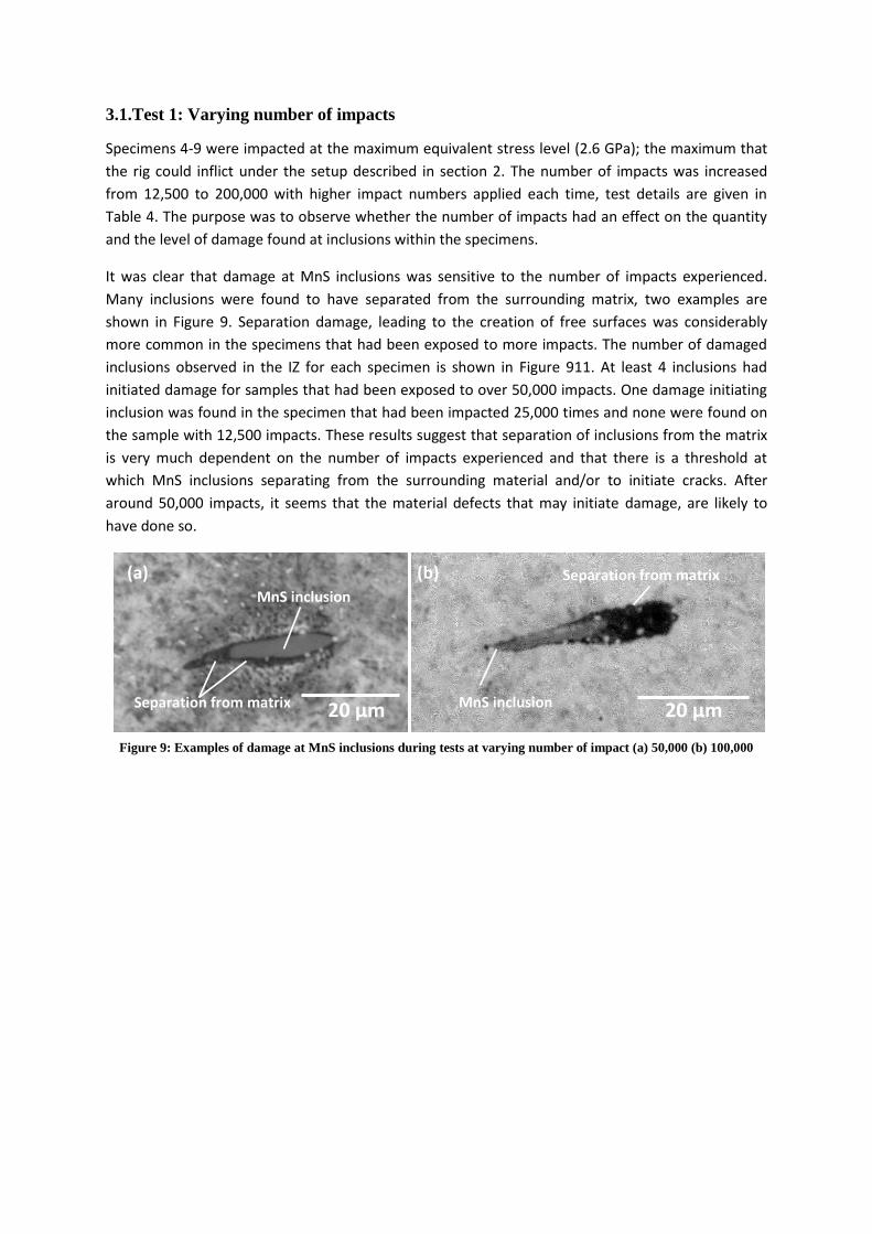
3.1.Test 1: Varying number of impacts
Specimens 4-9 were impacted at the maximum equivalent stress level (2.6 GPa); the maximum that
the rig could inflict under the setup described in section 2. The number of impacts was increased
from 12,500 to 200,000 with higher impact numbers applied each time, test details are given in
Table 4. The purpose was to observe whether the number of impacts had an effect on the quantity
and the level of damage found at inclusions within the specimens.
It was clear that damage at MnS inclusions was sensitive to the number of impacts experienced.
Many inclusions were found to have separated from the surrounding matrix, two examples are
shown in Figure 9. Separation damage, leading to the creation of free surfaces was considerably
more common in the specimens that had been exposed to more impacts. The number of damaged
inclusions observed in the IZ for each specimen is shown in Figure 911. At least 4 inclusions had
initiated damage for samples that had been exposed to over 50,000 impacts. One damage initiating
inclusion was found in the specimen that had been impacted 25,000 times and none were found on
the sample with 12,500 impacts. These results suggest that separation of inclusions from the matrix
is very much dependent on the number of impacts experienced and that there is a threshold at
which MnS inclusions separating from the surrounding material and/or to initiate cracks. After
around 50,000 impacts, it seems that the material defects that may initiate damage, are likely to
have done so.
Figure 9: Examples of damage at MnS inclusions during tests at varying number of impact (a) 50,000 (b) 100,000
20 ´マ 20 ´マ
MnS inclusion
Separation from matrix
(a) (b) Separation from matrix
MnS inclusion

3.2.Test 2: Varying contact stress
Specimens 10-14 were impacted 50,000 times, a quantity that was determined to be above the
threshold required for subsurface damage to initiate by observing the damaged samples from Test 1.
The maximum subsurface equivalent stress was increased from 2.15 GPa to 2.60 GPa (test
conditions are presented in Table 4), by altering impact velocity to increase impact energy and
therefore the surface contact stress level, to investigate the effect of changing this factor on the
resulting damage. Two examples of damaged inclusions found during varying contact stress tests are
presented in Figure 10. Figure 11 shows that as the subsurface equivalent stress increased, so did
the number of damaged inclusions. There seems to be a threshold for damage initiation (not
exclusively) above subsurface equivalent stresses of 2.48 GPa.
Figure 10: Example of damage at MnS inclusions during tests at varying subsurface stress (a) 2.48 GPa (b) 2.60 GPa.
Figure 11: Number of damaged inclusions for each test when subjected to various testing conditions
Region showing conditions (not exclusively) found to be above threshold for damage initiation
20 ´マ 20 ´マ
Crack initiation Separation from matrix (a) (b) Separation from matrix
Crack initiation

3.3.Test 3: High cycle number tests
Six specimens were subjected to high cycle number impact tests. Each was hit 1 million times at the
maximum impact energy that the test rig could provide. Two specimens were exposed to normal
impact loading and four at an angle of 45 degrees (compound impact) in order to introduce surface
traction. Impact angle was altered by replacing the striker shown in Figure 3 with an angled
alternative. Table 4 summarises the described test schedule.
Figure 12 displays images of five damaged inclusions found at depths of up to 285 ´マ beneath the
surface in specimens 15 and 16 (high cycle number tests with no surface traction). Major separation,
cracking of inclusions and crack initiation at inclusion tips has been observed. The table presented in
Figure 12 describes the damage in more detail. In summary, although the damage in specimens 1-2
is fairly extensive, the location of the damage is fairly local to the inclusions and crack propagation
has not occurred to any great extent. This is in agreement with the theory that mode 1 loading may
cause crack initiation and short growth, but some shear loading is required for further propagation.
Inclusion no.
Inclusion depth (たm)
Inclusion length
Damage description
1 89 31 Inclusion elongated, major separation to right side 2 130 37 Major break and cracking within inclusion, separation from surrounding matrix 3 144 8 Separation on left and right, crack propagation on right side 4 285 20 Separation and possible crack propagation on left side 5 95 32 Inclusion cracked, separation to left and right, significantly to right side
Figure 12: Five example inclusions damaged under normal impact loading of high impact cycles
Figure 13 displays that significantly more damage was caused by compound impact testing. Damage
found in specimens 15-16 was seen to a greater extent in specimens 17-20 after all specimens were
impacted 1,000,000 times. A WEC was found to be connected to inclusion 6 and possibly on a
number of others. Inclusion 6 was situated directly below the impact site at a depth of 98 ´マ. It
appears to have been internally cracked and broken up as well as initiating cracking in the bulk
material from its tips and WEA formation from its right hand end. The WEA seems to have formed
beneath a crack that has propagated from the right hand side. It is hypothesised that the increased
levels of Mode II/III shear loading caused by the surface traction force were necessary to propagate
the crack. The free surfaces created by the crack may then have rubbed against one another over
thousands of shear loading cycles and caused the formation of the WEA.
20 ´マ 20 ´マ
20 ´マ 20 ´マ 20 ´マ
1 2
3 4 5

Cracking was found on a number of inclusions, examples can be seen on inclusion 6, 9, 12 and 13.
Inclusion 9 is cracked along its length, similarly to inclusions a-e presented in Figure 2. These findings
show that compound impact creates more damage at inclusions and it may be that it is necessary in
order for damage to propagate significantly into the surrounding steel matrix.
Inclusion no.
Inclusion depth (たm)
Inclusion length
Comments
6 98 38 Major break up of inclusion, separation, cracking to left and right, major WEA to right 7 93 19 Cracking and possible small WEA to right 8 290 17 Cracking and possible small WEA to left 9 111 12 Inclusion split along length, crack from right side 10 220 18 Small crack to left, separation along right side and bottom 11 106 18 Separation to left and right, crack initiation to right 12 176 24 Inclusion split vertically, separation to left, crack initiation to left and right 13 178 67 Inclusion split, separation above and below, crack initiation to left
Figure 13: Example inclusions damaged (specimens 17-20) under compound impact testing of high impact cycles
Comparing the sizes of damaged inclusions over the high cycle number tests shows no strong trend
of damage with inclusion size. It appears that cracking can occur on inclusions of differing lengths
(from 8 to 67 ´マ). It is the case that damaged inclusions of shorter lengths (around 20 ´マ) were
more common than damaged longer inclusions (between 30 to 70 ´マ), however this is likely to be
that shorter inclusions are more populous than longer inclusions in general. It is likely that proximity
of inclusions to the point of subsurface maximum equivalent stress is a more important factor than
inclusion length itself. MultilifeTM
is a possible method to increase the lifetime of planetary WTGBs
that has been developed by Ricardo PLC, whereby the nominally stationary inner raceway is
periodically indexed around the planetary pin it is fitted to, thereby moving the loaded zone an
distributing the wear around the entire circumference of the raceway [36].
20 ´マ 20 ´マ
20 ´マ 10 ´マ 10 ´マ 20 ´マ
6 7
8 9 10 11
12 13

4. Conclusions
Having investigated factors affecting damage initiation caused in bearing steel under hammering
impact loading and recreated white etching cracking at MnS inclusions, the following conclusions
may be drawn.
1. Damage was created at subsurface MnS inclusions in bearing steel by using a reciprocating
hammering impact test rig at depths of up to 290 ´マ from the impact surface. Damaged
inclusions were between 8 に 67 ´マ in length, but were most commonly around 20 ´マ long.
Damage in the form of cracking of the bulk material and/or separation of the inclusion from the
bulk material appears to preferentially occur at the point of lowest radius of curvature at the
ends of the inclusion.
2. Increasing the number of loading cycles increased the level of damage caused, with increasing
cycle numbers causing damage at a higher number of inclusions. Tests of over 50,000 impact
cycles created damage at four or more inclusions in each tested sample and seemed to be a
threshold for damage initiation.
3. The level of subsurface equivalent stresses correlated with the amount of damage caused, with
higher stress levels causing damage at a higher number of inclusions. Tests of above 2.48 GPa
consistently created damage at more inclusions and seemed to be a threshold for damage
initiation.
4. Commonly observed damage features in wind turbine gearbox bearings including: the cracking
of MnS inclusions along their length, the propagation of the cracks from MnS inclusions into the
bulk material, the separation of MnS inclusions from the steel matrix, and the initiation and
propagation of WECs. These features can be replicated by exposing bearing steel to many cycles
(of the order of 1 million) of simultaneous hammering impact and surface sliding (compound
impact) at subsurface equivalent stresses of approximately 2.5 GPa. It is hypothesised that
surface traction is necessary for the formation of WECs due to increased cycles of Mode II/III
shear loading.
Acknowledgements
The authors would like to thank EPSRC Doctoral Training Grant (EP/J 503149/1) and Ricardo UK
Limited for funding this research.

References
1. European Wind Energy Association (2010), The European Wind Initiative: Wind Power Research
and Development to 2020, Brussels
2. Arántegui, R. L., Corsatea, T. and Suomalainen, K., (2012) 2012 JRC Wind Status Report,
European Commission.
3. Greco, A., Sheng, S., Keller, J., Eridemir, A. (2013) Material wear and fatigue in wind turbine
systems, Wear, 302(1-2), 1583に1591.
4. Musial, W., Butterfield, S. and McNiff, B. (2007) Improving wind turbine gearbox reliability,
National Renewable Energy Laboratory, Golden, Colorado.
5. Evans, M. -H. (2012) White structure flaking (WSF) in wind turbine gearbox bearings: effects of
'butterflies' and white etching cracks (WEC), Materials Science and Technology, 28(1), 3-22.
6. Errichello, R., Budny, R. and Eckert, R. (2013) Investigations of bearing failures associated with
white etching areas (WEAs) in wind turbine gearboxes, Tribology Transactions, 56(6), 1069-1076.
7. Luyckx, J. (2011) WEC failure mode on roller bearings. Presentation at Wind Turbine Tribology
Seminar, Hansen Transmissions.
8. Kotzalas, M. N. and Doll, G. L. (2010) Tribological advancements for reliable wind turbine
performance, Philosophical Transactions of the Royal Society A, 368(1929), 4829-4850.
9. Evans, M. -H., Richardson, A., Wang, L., and Wood, R. (2013) Serial sectioning investigation of
butterfly and white etching crack (WEC) formation in wind turbine gearbox bearings, Wear, 302
(1-2), 1573-1582.
10. International Organization for Standardization (2007), さB“ I“O 281: Dynamic load ratings and
rating life.ざ
11. Gegner, J. ふヲヰヱヱぶが さTヴキHラノラェキI;ノ ;ゲヮWIデゲ ラa ヴラノノキミェ HW;ヴキミェ a;キノ┌ヴWゲがざ キミ Tribology - Lubricants and
Lubrication, INTECH, 33-94.
12. Grabulov, A., Ziese, U. and Zandbergen, H. W. (2007) TEM/SEM investigation of microstructural
Iエ;ミェWゲ ┘キデエキミ デエW ┘エキデW WデIエキミェ ;ヴW; ┌ミSWヴ ヴラノノキミェ Iラミデ;Iデ a;デキェ┌W ;ミS ンどD Iヴ;Iニ ヴWIラミゲデヴ┌Iデキラミ
by focused ion beam, Scripta Materialia, 57(7), 635に638.
13. Uyama, U., Yamada, H., Hidaka H. and Mitamura, N. (2011) The effects of hydrogen on
microstructural change and surface originated flaking in rolling contact fatigue, Tribology Online,
6(2), 123-132.
14. Vegter, R. H. and Slycke, J. T. (2010) The Role of Hydrogen on Rolling Contact Fatigue Response
of Rolling Element Bearings, Journal of ASTM International, 7(2), 1に12.
15. Sims, C. and Dahle, F. (1938) Effect of Aluminium on the Properties of Medium Carbon Cast
Steel, AFS Transactions, 46, 65-132.

16. British Standards Instit┌デキラミ ふヲヰヰヵぶ さPD ΓΑヰぎヲヰヰヵ Wヴラ┌ェエデ ゲデWWノゲ aラヴ マWIエ;ミキI;ノ ;ミS ;ノノキWS
engineering purposes. Requirements for carbon, carbon manganese and alloy hot worked or
IラノS aキミキゲエWS ゲデWWノゲくざ
17. Bhadeshia, H. (2012) Steels for Bearings, Progress in Materials Science, 57, 268に435.
18. Evans, M.-H, Richardson, A., Wang, L., Wood, R. J. K. (2013) Serial sectioning investigation of
butterfly and white etching crack (WEC) formation in wind turbine gearbox bearings, Wear,
302(1-2) 1573-1582.
19. Perez-Unzueta, A. J. and Beynon, J. H. (1993) Microstructure and wear resistance of pearlitic rail
steels, Wear, 162-164 Part A, 173-182.
20. Dhua, S. K., Amitava R., Sen, S. K., Prasad, M. S., Mishra, K. B. and Jha, S. (2000) Influence of
nonmetallic inclusion characteristics on the mechanical properties of rail steel, Journal of
Materials Engineering and Performance, 9(6), 700-709.
21. Liu, C., Bassim, M. and Lawrence, S. (1993) Evaluation of fatigue-crack initiation at inclusions in
fully pearlitic steels, Materials Science and Engineering, 167(1-2), 108-113.
22. Chard, A. (2011) Deformation of inclusions in rail steel due to rolling contact, University of
Birmingham, Doctoral Thesis.
23. Bruce, T., Rounding, E., Long, H. and Dwyer-Joyce, R. S. (2015) Characterisation of white etching
crack damage in wind turbine gearbox bearings, Wear. In press, doi:10.1016/j.wear.2015.06.008
24. Lewis, M. W. J. and Tomkins, B. (2012) A fracture mechanics interpretation of rolling bearing
fatigue, Proc. IMechE Part J: J Engineering Tribology, 226(5), 389-405.
25. Stadler, K. and Stubenrauch, A. (2013) Premature bearing failures in industrial gearboxes., SKF,
Technical Report ATK 2013, Schweinfurt, Germany.
26. International Organisation for Standardization (2012) IEC 61400-4:2012: Wind turbines - Part 4:
Design requirements for wind turbine gearboxes.
27. Bruce, T., Long, H., Dwyer-Joyce, R. S. (2015) Dynamic modelling of wind turbine gearbox bearing
loading during transient events, IET Renewable Power Generation, doi: 10.1049/iet-
rpg.2014.0194.
28. Lund, T. B. (2010) Sub-surface initiated rolling contact fatigueねinfluence of non-metallic
inclusions, processing history, and operating conditions, Journal of ASTM International, 7(5), 1-
12.
29. Grabulov, A., Ziese, U., Zandbergen, H. W. (2007) TEM/SEM investigation of microstructural
Iエ;ミェWゲ ┘キデエキミ デエW ┘エキデW WデIエキミェ ;ヴW; ┌ミSWヴ ヴラノノキミェ Iラミデ;Iデ a;デキェ┌W ;ミS ンどD Iヴ;Iニ ヴWIラミゲデヴuction
by focused ion beam, Scripta Materialia, 57(7), 635に638.

30. Evans, M. H., Richardson, A., Wang, L. and Wood, R. (2013) Effect of hydrogen on butterfly and
white etching crack (WEC) formation under rolling contact fatigue (RCF) Wear, 306(1-2), 226に
241.
31. Slatter, T., Lewis, R., Jones, A. (2011) The influence of cryogenic processing on the impact wear
resistance of low carbon steel and lamellar graphite cast iron. Wear, 271(9-10), 1481-1489.
32. Slatter, T., Lewis, R. (2010) The influence of induction hardening on the impact wear resistance
of compacted graphite cast iron (CGI), Wear, 270(3-4), 302-311.
33. Slatter, T. (2010) Reducing Automotive Valve Train Recession with Surface Treatment, University
of Sheffield, Doctoral Thesis.
34. Ovako (2011) Ovako 825 product specification, Issue 4
35. Fujita, S. And Murakami, Y. (2013) A New Nonmetallic Inclusion Rating Method by Positive Use
of Hydrogen Embrittlement Phenomenon, Metallurgical and Materials Transactions A, 44(1)
303-322.
36. Wheals, J. C., Guern, P., Dwyer-Joyce, R. S., Marshall, M. and Howard, T. (2011) Ricardo
M┌ノデキLキaWゥ BW;ヴキミェ Pヴラェヴ;ママW aラヴ IミIヴW;ゲWS ‘Wノキ;Hキノキデ┞ ラa OaaゲエラヴW WキミS T┌ヴHキミWゲが European
Wind Energy Conference 2011, Brussels.