Embed Size (px)
Citation preview

Formal-Based Component Modelwith Support of Mobile Architecture
Marek Rychlý∗
Department of Information SystemsFaculty of Information Technology
Brno University of TechnologyBožetechova 2, 612 66 Brno, Czech Republic
AbstractIn this article, an approach to modelling of component-based systems and formal description of their behaviour isproposed. It is based on a novel component model definedby a metamodel in a logical view and by description inthe π-calculus in a process view. The model addressesdynamic aspects of software architectures including com-ponent mobility. Furthermore, a method of behaviouralmodelling of service-oriented architectures is proposed topass smoothly from service to component level and to de-scribe behaviour of a whole system as a single π-calculusprocess. The support of dynamic architecture and theintegration with service-oriented architecture compromisethe main advantages of the approach.
Categories and Subject DescriptorsD.2.11 [Software Architectures]: Languages; H.3.4[Systems and Software]: Distributed systems; D.2.4[Software/Program Verification]: Formal methods
KeywordsComponent-based development, Service-oriented archi-tecture, Component model, Formal specification
1. IntroductionGlobalisation of information society and its progressioncreate needs for extensive and reliable information tech-nology solutions. Several new requirements on informa-tion systems have emerged and significantly affected soft-ware architectures of these systems. The current informa-tion systems can not be realised as monoliths, but tend
∗Recommended by thesis supervisor:Assoc. Prof. Jaroslav ZendulkaDefended at Faculty of Information Technology, BrnoUniversity of Technology on February 19, 2010.
c© Copyright 2010. All rights reserved. Permission to make digitalor hard copies of part or all of this work for personal or classroom useis granted without fee provided that copies are not made or distributedfor profit or commercial advantage and that copies show this notice onthe first page or initial screen of a display along with the full citation.Copyrights for components of this work owned by others than ACMmust be honored. Abstracting with credit is permitted. To copy oth-erwise, to republish, to post on servers, to redistribute to lists, or touse any component of this work in other works requires prior specificpermission and/or a fee. Permissions may be requested from STU Press,Vazovova 5, 811 07 Bratislava, Slovakia.Rychlý, M. Formal-based Component Model with Support of MobileArchitecture. Information Sciences and Technologies Bulletin of theACM Slovakia, Vol. 2, No. 1 (2010) 13-25
to be distributed into networks of quite autonomous, butcooperative, components communicating asynchronouslyvia messages of appropriate formats. Loose binding be-tween those components allows to establish and destroytheir interconnections dynamically at runtime, on de-mand, and according to various aspects (e.g. quality ofservices provided or required by the components); to clonethe components and to move them into different contexts(known as “component mobility”); to create, destroy andupdate the components dynamically at runtime; etc.
The dynamic aspects of software architectures and thecomponent mobility bring new problems in the domain ofsoftware engineering, as it is described in Sec. 3.1. Thecomponent-based systems (CBSs) are getting involved,and a formal specification of evolution of their architec-tures is necessary, particularly in critical applications.The current problems and the state of the art, which issummarised in Sec. 2, provide us with adequate motiva-tion and form objectives of the research in Sec. 3.2.
To provide a method for modelling of CBSs and formaldescription of their behaviour, we propose an approachthat is based on a novel component model defined by ametamodel in a logical view in Sec. 4.2 and by descrip-tion in the π-calculus in a process view in Sec. 4.3. Weshow that the component model addresses the dynamicaspects of software architectures including the componentmobility. Furthermore, in Sec. 4.4, we propose a methodof behavioural modelling of service-oriented architectures(SOAs) to pass smoothly from service level to componentlevel and to describe behaviour of a whole system, servicesand components, as a single π-calculus process.
2. State of the ArtThis section deals with software architecture andcomponent-based development. It describes the state ofthe art of component models and architecture descriptionlanguages for dynamic and mobile architectures.
2.1 Software Architecture and Component-BasedDevelopment
The software architecture as “the fundamental organ-isation of a system, embodied in its components, theirrelationships to each other and the environment, and theprinciples governing its design and evolution” [15] canbe described using logical (structural) and process (be-havioural) view [16]. The first describes logical structure

14 Rychly, M.: Formal-Based Component Model with Support of Mobile Architecture
of the system, while the second describes concurrency andsynchronisation aspects of the system, e.g. behaviour ofcomponents, evolution of the architecture in time, etc.
We can distinguish three types of software architecturesaccording to their evolution in dependence on changesof their environment [27]: static architecture, dynamicarchitecture, and mobile (fully dynamic) architecture. Inthe static architecture, after initialisation of a system, newconnections between the system’s components can not becreated and existing connections can not be destroyed.In the dynamic architecture, there exist rules of evolutionof a software system in time (also called a “dynamics”),i.e. its components and connections are created and de-stroyed during the system’s runtime according to the rulesfrom its design-time. Finally, the mobile architecture isa dynamic architecture of a system where componentscan change their context in the system’s logical structureduring its execution (i.e.“component mobility”) accordingto rules from its design-time and functional requirements.
The component-based development (CBD, see [34])is a software development methodology strongly orientedto composability and re-usability in a software system’sarchitecture. In the CBD, from a structural point of view,a system is composed of components, self-contained enti-ties accessible through well-defined interfaces. A connec-tion of compatible interfaces of cooperating components isrealised via their bindings (connectors). Actual organisa-tion of interconnected components is called configuration.
A static architecture has only one way how to connectcomponents and connectors into a resulting system, i.e.there is only one configuration. Dynamic and mobile ar-chitectures enable software systems to change their archi-tectures during their runtimes. It means runtime modifi-cations of the configuration, i.e. reconfiguration. Descrip-tion of the reconfiguration [27] includes description of spe-cific actions, which are consumed and produced by a sys-tem (inputs, outputs, and internal actions); relationshipsbetween the actions, how the input actions are processedby the system; and changes of an architecture accordingto the actions, i.e. processes of creation and destructionof its components, connectors and reconfiguration.
In CBD, components can be primitive or composite. Theprimitive components are realised directly, beyond thescope of architecture description. The composite compo-nents are decomposable into systems of subcomponentsat the lower level of architecture description. This com-position forms a component hierarchy.
2.2 Component Models and ArchitectureDescription Languages
Component models are specific metamodels of softwarearchitectures supporting the CBD. The component mod-els should define syntax, semantics, and composition ofcomponents [17]. They are systems of rules for compo-nents, connectors, configurations, rules for changes ac-cording to the dynamic architecture (rules for reconfigu-rations), etc. Several component models has been pro-posed [18] including the models. Those models differ par-ticularly in definitions of connectors (explicit or implicitdefinitions) and implementation of advanced features ofdynamic or mobile architectures. In this section, we focuson component models with formal bases.
Component model Wright [1] uses the process calculus ofCommunicating Sequential Processes (CSP). The compo-nent model defines a component as a structure composedof two parts, an interface and a “component-spec”. Theinterface consists of a finite number of required and pro-vided ports and corresponding CSP processes for specificinput and output events, respectively. The component-spec defines interactions between the ports as a composi-tion of their CSP processes. Interactions of componentsare defined by connectors and described by specific CSPprocesses. Finally, a configuration describes actual bind-ings of the components and the connectors. Limitations ofWright are given by the used formalism (the descriptionsin CSP support only systems with static architectures).
Component model Darwin [19, 12] allows distributed sys-tems to be hierarchically composed of sets of componentinstances and their interconnections at each level of thehierarchy. Each component is defined by its required andprovided services (interfaces), which allow it to interactwith other components. Composite components are de-fined by declaring instances of internal components and“required-provided” bindings between those components.Services of the internal components that cannot be sat-isfied can be declared as visible at a higher level of thehierarchy, as the services of the composite components.Darwin [19] allows to describe behaviour of componentsin the calculus of mobile processes (the π-calculus). Itsupports a subset of dynamic architectures, which permitsdynamic instantiation of new components at runtime, butdoes not allow specification of dynamic bindings or com-ponent removal. Later, Tracta approach [12] allows todescribe behaviour of components as Labelled TransitionSystems (LTSs) with an algebra of Finite State Processes(FSP) as a specification language.
In component model SOFA [29], a part of SOFA project(SOFtware Appliances), a software system is describedas a hierarchical composition of primitive and compositecomponents. A component is an instance of a template,which is described by its frame and architecture. Theframe is a“black-box”specification view of the componentdefining its provided and required interfaces. A primitivecomponent has a primitive architecture and it is directlyimplemented by a software system. The architecture ofa composite component is a “grey-box” implementationview, which describes its direct subcomponents and theirinterconnections via interfaces: binding of required toprovided interfaces, delegating of a component’s providedinterfaces to provided interfaces of the component’s sub-component, subsuming of required interfaces of a compo-nent’s subcomponent to the component’s required inter-faces, and exempting of subcomponent’s interfaces fromany connection. SOFA uses a Component Definition Lan-guage (CDL, [22]), which extends features of OMG IDLto allow specification of software components. Behaviourof a component (its interface, frame, and architecture) isformally described by means of behaviour protocols [37].The protocols support static architecture, but allow to de-scribe dynamic update of an architecture of a componentduring a system’s runtime.
Component model SOFA 2.0 [8], as a new version of com-ponent model SOFA, aims at removing several limita-tions of the original version, mainly the lack of supportof dynamic reconfigurations, well-structured and exten-sible control parts of components, and multiple styles of

Information Sciences and Technologies Bulletin of the ACM Slovakia, Vol. 2, No. 1 (2010) 13-25 15
communication between components. It permits dynamicreconfigurations predefined at design-time by reconfigura-tion patterns: nested factory, component removal, andutility interface. The utility interfaces can be freelypassed among components and bound independently oftheir components’ levels in architecture hierarchy (then,SOA becomes a specific case of a component model whereall components (services) are interconnected solely viatheir utility interfaces).
Component model Fractal [6, 7] forms a component outof two parts: a controller and a content. The content ofa composite component is composed of a finite number ofnested components. Those subcomponents are controlledby the controller of the enclosing component, which actsas a composition operator. A component can interactwith its environment through operations at external in-terfaces of the component’s controller, while internal in-terfaces are accessible only from the component’s sub-components. A functional interface requires or providesfunctionalities of a component, while a control interfaceis a server interface, which provides operations for intro-spection of the component and to control the component’sconfiguration, namely attribute, binding, content, andlife-cycle control. Operations on functional interface cannot fire control operations. Behaviour of Fractal compo-nents can be formally described by means of parametrisednetworks of communicating automata language [5]. Be-haviour of each primitive component is modelled as a fi-nite state parametrised labelled transition system (pLTS),while behaviour of a composite component is defined usinga parametrised synchronisation network (pNet): a set ofglobal parametrised actions and a transducer, which is asynchronisation product of the subcomponents’ pLTSs.Changes of the transducer’s state represent possible re-configurations of the composite component’s architecture.
Architecture description languages (ADLs, see [35])are languages for describing software systems’ architec-tures, which focus on high-level structures of overall appli-cations rather than implementation details of any specificsource modules. The ADLs can be parts of componentmodels, where they are used for description of a softwaresystem’s logical structure (the logical view, see Sec. 2.1).Several ADLs have been proposed [21]: for modellingof software architectures within a particular domain, asgeneral-purpose architecture modelling languages, withand without component models and formal bases, etc. Inthe rest of this section, we aim at the ADLs that do notdepend directly on component models.
Language ACME [11] has been developed in order estab-lish a common basis for the ADLs and to enable inte-gration of their support tools. It defines components andconnectors, systems (as configurations of components andconnectors), ports (as interfaces of a component), roles(of interfaces of a connector, which they act in commu-nication), representations (hierarchical decompositions ofcomponents and connectors), and rep-maps (mappingsbetween a composite component’s or connector’s internalarchitecture and its external interface). Other aspects ofarchitectural description can be represented with prop-erty lists. The ACME does not provide any certain se-mantic model. The property lists, structural constraints,etc. must be described in terms of other ADLs’ semanticmodel. Therefore, the ACME itself is not suitable for de-scription of a system’s software architecture and should be
used only in association with other ADL (where ACMEacts as the ADL’s exchange language).
Unified Modelling Language (UML, see [26]) providesthree possible strategies for modelling of software archi-tectures [20]: to use UML “as is”, to constrain its meta-model using UML’s built-in extension mechanisms, andto extend the metamodel by new architectural concepts.Each approach has potential advantages and disadvan-tages (e.g. limited semantics of standard UML or incom-patiblity of the extensions with UML-compliant tools).The UML 2 has introduced description of hierarchicalarchitecture of CBSs [3] by means of structured classes,i.e. the classes that allow nesting of other classes. Itsspecification [26] states that “a component represents amodular part of a system that encapsulates its contentsand whose manifestation is replaceable within its envi-ronment”. The components are drawn as specific classesstereotyped «component» interconnected by means of “as-sembly connectors” binding their interfaces in a “lollipop”style notation. Moreover, the components can be used torepresent many different entities, which are distinguishedby several stereotypes.
ArchWare ADL (see [4]) provides a core (runtime) struc-ture and behaviour constructs to describe dynamic soft-ware architectures. It is a formal specification languagedesigned to be executable (by a virtual machine) and tosupport automated verification. The ArchWare ADL isfounded on three formal models: π-ADL [27] that con-tains the core structure and behaviour constructs withthe higher-order typed π-calculus as a formal basis; σπ-ADL [4] that contains style constructs for defining a basecomponent-connector style and other derived styles; andµπ-AAL that is extension of the modal µ-calculus fordescription of behavioural and structural properties ofcommunicating and mobile architectural elements. Thebehaviour constructs from the base language copy the π-calculus constructs.
3. MotivationThis section aims at clarifying the motivation of the re-search. A problem is stated in terms of the state of the artfrom Sec. 2 and objectives of the research are established.The detailed description of the research objectives can befound in the author’s dissertation [31].
3.1 Statement of the ProblemThe current component models and ADLs have manyshortcomings in support of mobile architectures, incor-poration of component-based design into SOA and intosoftware development processes in general. Their formalbases or models usually do not consider component mo-bility (e.g. pNets in Fractal [5], behaviour protocols inSOFA [37], and reconfiguration patterns in SOFA 2.0[14]), prefer strict isolation of functional parts of com-ponents from their controllers (functional operations cannot fire control operations; e.g. restrictions of pNets ina formal description of Fractal components [5]), do notsupport description of SOAs where individual servicescan be implemented as underlying CBSs (e.g. in Fractalcomponent model [7] or in the ArchWare project [4]), etc.
Moreover, the component models do not describe re-lated methods of CBD and their incorporation into well-established software development processes of standardsoftware systems [13]. Modelling of the CBSs during

16 Rychly, M.: Formal-Based Component Model with Support of Mobile Architecture
the development processes brings many issues (e.g. as aconsequence of different conceptions of components in thecomponent models [17], in component diagrams of UML[26] or software component architectures [28]).
3.2 Objectives of the ResearchThe statement of the problems of current componentmodels and corresponding ADLs provides us with ade-quate motivation. A general objective of the research is todesign a component model for mobile architectures. Themodel has to provide suitable formal basis and should beapplicable to modelling of CBSs as well as SOAs.
Specific objectives of the research that fulfil the general ob-jective include: the development of the component modeland its formal basis supporting features of mobile archi-tectures and addressing the current issues of CBD; inte-gration of functional operations and relevant behaviourof components with control operations enabling dynamicreconfiguration; a method of application of the compo-nent model in SOAs with mapping rules between servicesand CBSs described by means of the component model;description of a supporting environment that allows inte-gration of the component model and utilisation of its for-mal basis into software development processes; and finally,demonstration of an application of the proposed approachon a case study and evaluation of its effectiveness androbustness over the existing conventional approaches.
4. Methods of RealisationIn order to reach the stated objectives, we propose ahigh-level component model addressing the current issuesof CBD. It allows dynamic reconfiguration, componentmobility, and combination of control and business logicof components. Behavioural description of individualcomponents and their mutual communication in CBSs isbased on the π-calculus.
The component model can be presented in two views:logical (structural) view and process (behavioural) view.At first, we introduce the component model’s metamodel,which describes basic entities of the component model andtheir relations. The second view, is focused on behaviourof the component model’s entities, especially on compo-nent mobility. Finally, we describe behaviour of servicesin SOAs and their underlying implementations as CBSs.
4.1 Formal BaseTo describe behaviour of components in CBSs and ser-vices in SOAs in formal way, we use the π-calculus, knownalso as a calculus of mobile processes [23]. It allows mod-elling of systems with dynamic communication structures(i.e. mobile processes) by means of two concepts: pro-cesses and names. The processes are active communicat-ing entities, primitive or expressed in π-calculus, while thenames are anything else, e.g. communication links (knownas “ports”), variables, constants, etc. Processes use names(as communication links) to interact, and they pass names(as variables, constants, and communication links) to an-other processes by mentioning them in the interactions.Names received by a process can be used and mentionedby it in further interactions (e.g. as communication links).We suppose basic knowledge of the fundamentals of theπ-calculus, a theory of mobile processes, according to [33]:
• x〈y〉.P is an output prefix that can send name yvia name x (i.e. via the communication link x) andcontinue as process P ;
• x(z).P is an input prefix that can receive any namevia name x and continue as process P with thereceived name substituted for every free occurrenceof name z in the process;
• P + P ′ is a sum of capabilities of P together withcapabilities of P ′ processes, it proceeds as eitherprocess P or process P ′, i.e. when a sum exercisesone of its capabilities, the others are rendered void;
• P | P ′ is a composition of processes P and P ′,which can proceed independently and can interactvia shared names;
•∏m
i=1 Pi = P1 | P2 | . . . | Pm is a multi-compositionof processes P1, . . . , Pm, for m ≥ 3, which can pro-ceed independently interacting via shared names;
• (z)P is a restriction of the scope of name z in processP (the scope may change as a result of interactionbetween processes);
• (x)P = (x1, x2, . . . , xn)P = (x1)(x2) . . . (xn)P is amulti-restriction of the scope of names x1, . . . , xn toprocess P , for n ≥ 2;
• !P is a replication that means an infinite composi-tion of processes P or, equivalently, a process satis-fying the equation !P = P | !P .
The π-calculus processes can be parametrised as an ab-straction, an expression of form (x).P . When abstraction(x).P is applied to argument y it yields process P {y/x},i.e. process P with y substituted for every free occurrenceof x. The abstractions can be used in two types of appli-cation: pseudo-application and constant application.
Pseudo-application F 〈y〉 of abstraction Fdef= (x).P is an
abbreviation of substitution P {y/x}. On the contrary,the constant application is a real syntactic construct,which allows to reduce a form of process Kbyc, sometimesreferred as an instance of process constant K, according
to a recursive definition of process constant K∆= (x).P .
The result of the reduction yields process P {y/x}.
4.2 Component Model: Logical ViewThe component model for mobile architectures is de-scribed as a metamodel in the context of a four-layermodelling architecture. The metamodel is implementedin OMG’s Meta Object Facility (MOF, [24]), which isused as a meta-metamodel. The modelling architecturecomprises the following four layers:
M0 An information layer, which is comprised of the ac-tual data objects. It contains particular instancesof CBSs, their runtime configurations, specific de-ployments of their components and connectors, etc.
M1 A model layer, which contains models of the M0data. The models include structure and behaviourmodels that describe different perspectives of CBSssuch as, for example, UML component models.
M2 A metamodel layer provides a language that can beused to build M1 models. Component models fall inthis layer, as well as models of the UML language.

Information Sciences and Technologies Bulletin of the ACM Slovakia, Vol. 2, No. 1 (2010) 13-25 17
M3 A meta-metamodel layer, which is used to definemodelling languages. It holds a model of the in-formation from M2, e.g. MOF.
In the four-layer modelling architecture, the models inlower layers use classes from metamodels in upper layersto create their objects. In the context of CBD, a specificCBS (layer M0) contains instances of elements from itsmodel (layer M1). The model contains instances froma specific component model (a metamodel in layer M2),which is described by a given meta-metamodel (layer M3).
4.2.1 MetamodelThis section deals with description of the componentmodel for mobile architectures as a metamodel. Themetamodel is defined in Meta Object Facility version 2.0(MOF, [24]). MOF is in layer M3 in the four-layer mod-elling architecture (see Sec. 4.2). It is defined in twoparts: Essential MOF and Complete MOF (EMOF andCMOF). The EMOF contains packages Basic, Reflec-tion, Identifiers, and Extension, which form a mini-mal set of modelling elements to define simple metamod-els. The CMOF extends EMOF by Constructs packagefrom UML 2 Core (see [25]). For purposes of this article,the EMOF is sufficient to describe the component model.
The component model, as a model of layer M2 in the four-layer modelling architecture, can be described by meansof UML 2 diagrams in two contexts: as an object diagramof instances of EMOF classes from layer M3 (entities inlayer M2 are instances of classes in layer M3, i.e. it isdescribed as “a model”) and as a class diagram from layerM1 (entities in layer M1 are instances of classes in layerM2, i.e. it is described as “a metamodel”).
For better clearness, the component model will bedescribed as an UML 2 class diagram from layerM1. To reuse well-established concepts of MOF,the component model’s metamodel extends EMOFclasses EMOF::NamedElement, EMOF::TypedElement, andEMOF::Operation, which are outlined in Fig. 1. A com-plete definition of the EMOF classes can be found in [24].
Components and Interfaces. Fig. 2 describes the firstpart of the component model as an extension of EMOF.The metamodel defines an abstract component, its re-alisations as a primitive component and a compositecomponent, and their interfaces. All classes of themetamodel inherits (directly or indirectly) from classEMOF::NamedElement in package Basic of EMOF.
In our approach, a component as an active communicat-ing entity of a CBS can be described according to twoviews: as an abstract component without considering itsinternal structure (in a “black-box” view) and as a com-ponent realisation in the form of a primitive componentor a composite component (in a “grey-box” view). Theabstract component (class Component in the metamodel)can communicate with neighbouring components via itsinterfaces (class Interface). The interfaces can be pro-vided (class ExternalProvInterface) or required (classExternalReqInterface) by the component.
The component realisation can be primitive or composite.The primitive component realisation (class Primitive-
Component) is implemented directly, beyond the scope
of architecture description. It is a “black-box” with de-scribed observable behaviour (attribute behaviouralDe-
scription). The composite component realisation (classCompositeComponent), as a “grey-box”, is decomposableon a system of subcomponents at the lower level of ar-chitecture description. Those subcomponents are repre-sented by abstract components (class Component and rela-tion “consists of”). Moreover, every composite componentrealisation can communicate with its subcomponents viaits provided (class InternalProvInterface) and required(class InternalReqInterface) internal interfaces (rela-tions“provides inside”and“requires inside”, respectively).
The specific interfaces have to implement methodsgetOwner(), which return their owners, i.e. objects thatact as the abstract components in a case of the abstractcomponent interfaces or as instances of the compositecomponent realisations in a case of their internal inter-faces (see owner roles in the relations in Fig. 2).
Composite Components and Binding. Binding is a con-nection of required and provided interfaces of the identicaltypes into a reliable communication link. It is describedin Fig. 3. Interfaces of a component (classes Exter-
nalProvInterface and ExternalReqInterface) can beprovided to and required from its neighbouring compo-nents, while interfaces of a composite component reali-sation (classes InternalProvInterface and InternalRe-
qInterface) can be provided to and required from its sub-components only. Therefore, we distinguish three typesof the binding (the realisations of class Binding):
1. Binding of provided interfaces to required interfacesin the same composite component realisation is rep-resented by class BindSiblings. The interfaces haveto be internal interfaces of the composite compo-nent realisation or external interfaces of subcompo-nents in the same composite component realisation.The binding interconnects required interfaces (classRequiredInterface) via relations “bound from” toprovided interfaces (class ProvidedInterfaces) viarelations “bound to”.
2. Binding of external provided interfaces of a compos-ite component realisation to its internal required in-terfaces is represented by class BindInward. The ex-ternal interfaces are provided to neighbouring com-ponents of the composite component acting as anabstract component (relation “imports from” an in-stance of class ExternalProvInterface), while theinternal interfaces are required from the compositecomponent’s subcomponents (relation “exports to”an instance of class ExternalReqInterfaces).
3. Binding of internal provided interfaces of a com-posite component realisation to its external requiredinterfaces is represented by class BindOutward. Theinternal interfaces are provided to the compos-ite component’s subcomponents (relation “exportsfrom”an instance of class InternalProvInterface),while the external interfaces are required fromneighbouring components of the composite compo-nent acting as an abstract component (relation “ex-ports to” an instance of ExternalReqInterfaces).
The bindings (i.e. instances of the realisations of classBinding) are owned by the composite component realisa-

18 Rychly, M.: Formal-Based Component Model with Support of Mobile Architecture
+ name : string
NamedElement(CM::metamodel::EMOF)
Operation(CM::metamodel::EMOF)
TypedElement(CM::metamodel::EMOF)
+ isOrdered : boolean = false+ isUnique : boolean = false+ lower : int+ upper : int
MultiplicityElement(CM::metamodel::EMOF)
Parameter(CM::metamodel::EMOF)
0..*+ ownedParameter
+ operat ionowns
Figure 1: A simplified part of the EMOF [24] with classes that will be extended in the metamodel.
Component
+ behaviouralDescript ion
PrimitiveComponent
CompositeComponent
+ name : string
NamedElement(CM::metamodel::EMOF)
+ getOwner() : Component
Interface
ProvidedInterface
RequiredInterface
ExternalProvInterface
ExternalReqInterface
InternalProvInterface
InternalReqInterface
0..*
1
+ required
+ owner
0..*
1
+ provided
+ owner
0..*0..1
+ subcomponent
+ parent
0..*
1+ providedIn
+ owner
0..*
1
+ requiredIn
+ owner
requires inside
provides inside
requires
provides
consists of
Figure 2: Abstract component, realisations, and interfaces in the metamodel.
Binding BindOutwardBindInward
+ name : string
NamedElement(CM::metamodel::EMOF)
TypeOfBinding
ProvidedInterface
RequiredInterface
ExternalProvInterface
ExternalReqInterface
InternalProvInterface
InternalReqInterface
BindSiblings
CompositeComponent
1
0..1
+ provided
10..*
+ provided
1
0..1
+ required
1
0..1
+ required
1
0..1
+ required
*
1
+ binding+ owner
1
0..1
+ provided
0..1
0..*
+ typehas
imports from
exports to
imports to
exports from
bound from
bound to
contains
Figure 3: Binding and its different realisations between interfaces of a composite component realisationin the metamodel. Classes CompositeComponent and ...Interface are identical to the classes in Fig. 2.
Information Sciences and Technologies Bulletin of the ACM Slovakia, Vol. 2, No. 1 (2010) 13-25 19
tions. Each binding can have a type (class TypeOfBind-
ing), which can describe a communication style (bufferedand unbuffered connection), a type of synchronisation(blocking and output non-blocking), etc.
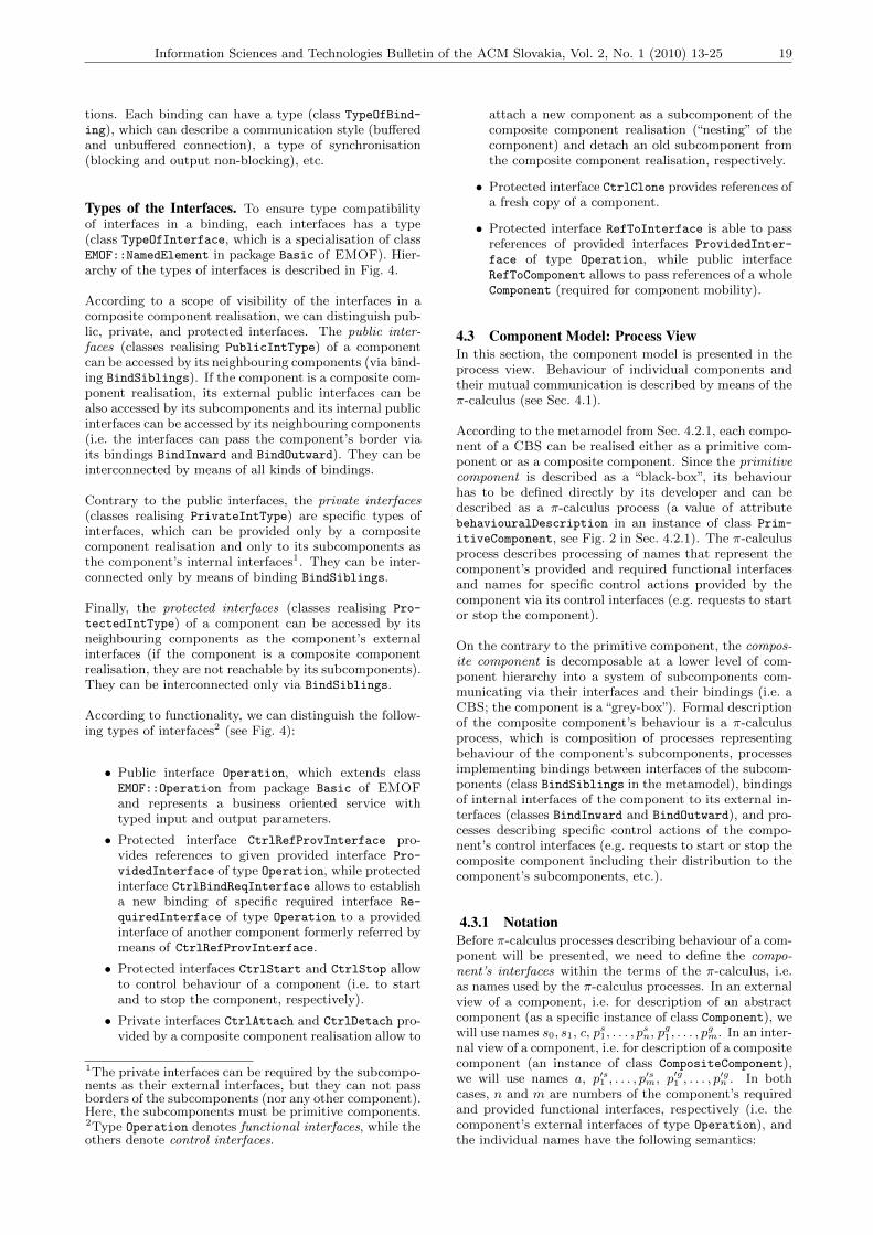
Types of the Interfaces. To ensure type compatibilityof interfaces in a binding, each interfaces has a type(class TypeOfInterface, which is a specialisation of classEMOF::NamedElement in package Basic of EMOF). Hier-archy of the types of interfaces is described in Fig. 4.
According to a scope of visibility of the interfaces in acomposite component realisation, we can distinguish pub-lic, private, and protected interfaces. The public inter-faces (classes realising PublicIntType) of a componentcan be accessed by its neighbouring components (via bind-ing BindSiblings). If the component is a composite com-ponent realisation, its external public interfaces can bealso accessed by its subcomponents and its internal publicinterfaces can be accessed by its neighbouring components(i.e. the interfaces can pass the component’s border viaits bindings BindInward and BindOutward). They can beinterconnected by means of all kinds of bindings.
Contrary to the public interfaces, the private interfaces(classes realising PrivateIntType) are specific types ofinterfaces, which can be provided only by a compositecomponent realisation and only to its subcomponents asthe component’s internal interfaces1. They can be inter-connected only by means of binding BindSiblings.
Finally, the protected interfaces (classes realising Pro-
tectedIntType) of a component can be accessed by itsneighbouring components as the component’s externalinterfaces (if the component is a composite componentrealisation, they are not reachable by its subcomponents).They can be interconnected only via BindSiblings.
According to functionality, we can distinguish the follow-ing types of interfaces2 (see Fig. 4):
• Public interface Operation, which extends classEMOF::Operation from package Basic of EMOFand represents a business oriented service withtyped input and output parameters.
• Protected interface CtrlRefProvInterface pro-vides references to given provided interface Pro-
videdInterface of type Operation, while protectedinterface CtrlBindReqInterface allows to establisha new binding of specific required interface Re-
quiredInterface of type Operation to a providedinterface of another component formerly referred bymeans of CtrlRefProvInterface.
• Protected interfaces CtrlStart and CtrlStop allowto control behaviour of a component (i.e. to startand to stop the component, respectively).
• Private interfaces CtrlAttach and CtrlDetach pro-vided by a composite component realisation allow to
1The private interfaces can be required by the subcompo-nents as their external interfaces, but they can not passborders of the subcomponents (nor any other component).Here, the subcomponents must be primitive components.2Type Operation denotes functional interfaces, while theothers denote control interfaces.
attach a new component as a subcomponent of thecomposite component realisation (“nesting” of thecomponent) and detach an old subcomponent fromthe composite component realisation, respectively.
• Protected interface CtrlClone provides references ofa fresh copy of a component.
• Protected interface RefToInterface is able to passreferences of provided interfaces ProvidedInter-
face of type Operation, while public interfaceRefToComponent allows to pass references of a wholeComponent (required for component mobility).
4.3 Component Model: Process ViewIn this section, the component model is presented in theprocess view. Behaviour of individual components andtheir mutual communication is described by means of theπ-calculus (see Sec. 4.1).
According to the metamodel from Sec. 4.2.1, each compo-nent of a CBS can be realised either as a primitive com-ponent or as a composite component. Since the primitivecomponent is described as a “black-box”, its behaviourhas to be defined directly by its developer and can bedescribed as a π-calculus process (a value of attributebehaviouralDescription in an instance of class Prim-
itiveComponent, see Fig. 2 in Sec. 4.2.1). The π-calculusprocess describes processing of names that represent thecomponent’s provided and required functional interfacesand names for specific control actions provided by thecomponent via its control interfaces (e.g. requests to startor stop the component).
On the contrary to the primitive component, the compos-ite component is decomposable at a lower level of com-ponent hierarchy into a system of subcomponents com-municating via their interfaces and their bindings (i.e. aCBS; the component is a “grey-box”). Formal descriptionof the composite component’s behaviour is a π-calculusprocess, which is composition of processes representingbehaviour of the component’s subcomponents, processesimplementing bindings between interfaces of the subcom-ponents (class BindSiblings in the metamodel), bindingsof internal interfaces of the component to its external in-terfaces (classes BindInward and BindOutward), and pro-cesses describing specific control actions of the compo-nent’s control interfaces (e.g. requests to start or stop thecomposite component including their distribution to thecomponent’s subcomponents, etc.).
4.3.1 NotationBefore π-calculus processes describing behaviour of a com-ponent will be presented, we need to define the compo-nent’s interfaces within the terms of the π-calculus, i.e.as names used by the π-calculus processes. In an externalview of a component, i.e. for description of an abstractcomponent (as a specific instance of class Component), wewill use names s0, s1, c, ps1, . . . , p
sn, pg1, . . . , p
gm. In an inter-
nal view of a component, i.e. for description of a compositecomponent (an instance of class CompositeComponent),we will use names a, p′s1 , . . . , p
′sm, p′g1 , . . . , p
′gn . In both
cases, n and m are numbers of the component’s requiredand provided functional interfaces, respectively (i.e. thecomponent’s external interfaces of type Operation), andthe individual names have the following semantics:
20 Rychly, M.: Formal-Based Component Model with Support of Mobile Architecture
CtrlRefProvInterface
CtrlBindReqInterface
ProtectedIntType PublicIntType
Operation
CtrlStart
CtrlStop
CtrlClone
CtrlAttach CtrlDetach
RefToProvInterface RefToComponent
PrivateIntType
TypeOfInterface
Operation(CM::metamodel::EMOF)
+ name : string
NamedElement(CM::metamodel::EMOF)+ getOwner() : Component
Interface
Component
RequiredInterface
ProvidedInterface
1
+ operat ion
1
*
+ type
1
+ component
1
0..1
+ operat ion
+ referrer
1
0..1
+ operat ion
+ binder
has
refers to
refers to
sets binding from
gets reference to
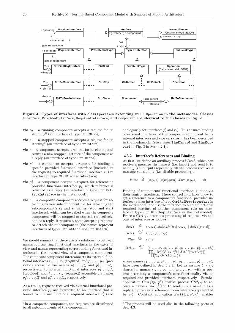
Figure 4: Types of interfaces with class Operation extending EMOF::Operation in the metamodel. ClassesInterface, ProvidedInterface, RequiredInterface, and Component are identical to the classes in Fig. 2.
via s0 – a running component accepts a request for itsstopping3 (an interface of type CtrlStop),
via s1 – a stopped component accepts a request for itsstarting3 (an interface of type CtrlStart),
via c – a component accepts a request for its cloning andreturns a new stopped instance of the component asa reply (an interface of type CtrlClone),
via psi – a component accepts a request for binding aspecific provided functional interface (included inthe request) to required functional interface ri (aninterface of type CtrlBindReqInterface),
via pgj – a component accepts a request for referencingprovided functional interface pj , which reference isreturned as a reply (an interface of type CtrlRef-
ProvInterface in the metamodel),
via a – a composite component accepts a request for at-taching its new subcomponent, i.e. for attaching thesubcomponent’s s0 and s1 names (stop and startinterfaces), which can be called when the compositecomponent will be stopped or started, respectively,and as a reply, it returns a name accepting requeststo detach the subcomponent (the names representinterfaces of types CtrlAttach and CtrlDetach).
We should remark that there exists a relationship betweennames representing functional interfaces in the externalview and names representing corresponding functional in-terfaces in the internal view of a composite component.The composite component interconnects its external func-tional interfaces r1, . . . , rn (required) and p1, . . . , pm (pro-vided) accessible via names ps1, . . . , p
sn and pg1, . . . , p
gm,
respectively, to internal functional interfaces p′1, . . . , p′n
(provided) and r′1, . . . , r′m (required) accessible via names
p′g1 , . . . , p′gn and p′s1 , . . . , p
′sm, respectively.
As a result, requests received via external functional pro-vided interface pj are forwarded to an interface that isbound to internal functional required interface r′j (and
3In a composite component, the requests are distributedto all subcomponents of the component.
analogously for interfaces p′i and ri). This ensures bindingof external interfaces of the composite component to itsinternal interfaces and vice versa, as it has been describedin the medamodel (see classes BindInward and BindOut-
ward in Fig. 3 in Sec. 4.2.1).
4.3.2 Interface’s References and BindingAt first, we define an auxiliary process Wire4, which canreceive a message via name x (i.e. input) and send it toname y (i.e. output) repeatedly till the process receives amessage via name d (i.e. disable processing).
Wire∆= (x, y, d).(x(m).y〈m〉.Wirebx, y, dc + d)
Binding of components’ functional interfaces is done viatheir control interfaces. These control interfaces allow toget a reference to a component’s functional provided in-terface (via an interface of type CtrlRefProvInterface inthe metamodel) and use the reference to bind a functionalrequired interface of another component (via an inter-face of type CtrlBindReqInterface in the metamodel).Process CtrlIfs describes processing of requests via thecontrol interfaces as follows:
SetIf∆= (r, s, d).s(p).(d.Wirebr, p, dc | SetIfbr, s, dc)
GetIfdef= (p, g).g(r).r〈p〉
Plugdef= (d).d
CtrlIfsdef= (r1, . . . , rn, ps1, . . . , p
sn, p1, . . . , pm, p
g1, . . . , p
gm).
(∏n
i=1(rdi )(Plug〈rdi 〉 | SetIfbri, psi , rdi c)
|∏m
j=1!GetIf〈pj , pgj 〉)
where names r1, . . . , rn, ps1, . . . , psn, p1, . . . , pm, pg1, . . . , p
gm
have been defined in Sec. 4.3.1. Let us assume CtrlIfsshares its names r1, . . . , rn and p1, . . . , pm with a pro-cess describing a component’s core functionality via itsrequired and provided interfaces, respectively. Pseudo-application GetIf〈pj , pgj 〉 enables process CtrlIfs to re-ceive a name x via pgj and to send pj via name x as areply (it provides a reference to an interface representedby pj). Constant application SetIfbri, psi , rdi c enables
4The process will be used also in the following parts ofSec. 4.3.
Information Sciences and Technologies Bulletin of the ACM Slovakia, Vol. 2, No. 1 (2010) 13-25 21
process CtrlIfs to receive a name x via psi , which willbe connected to ri by means of a new instance of processWire (it binds a required interface represented by ri to aprovided interface represented by x). To remove a formerbinding of ri, a request is sent via rdi (in case it is the firstbinding of ri, i.e. there is no former binding, the requestis accepted by pseudo-application Plug〈rdi 〉).
In a composite component, the names representing ex-ternal functional interfaces r1, . . . , rn, p1, . . . , pm are con-nected to the names representing internal functional in-terfaces p′1, . . . , p
′n, r′1, . . . , r
′m. Requests received via ex-
ternal functional provided interface pj are forwarded toan interface that is bound to internal functional requiredinterface r′j (and analogously for interfaces p′i and ri).This behaviour is described in process CtrlEI :
CtrlEIdef= (r1, . . . , rn, p1, . . . , pm, r
′1, . . . , r
′m, p
′1, . . . , p
′n).
(
n∏i=1
(d)Wirebri, p′i, dc |m∏
j=1
(d)Wirebr′j , pj , dc)
4.3.3 Control of a Component’s Life-cycleControl of a composite component’s life-cycle5 can bedescribed as process CtrlSS .
Dist∆= (p,m, r).(p〈m〉.Distbp,m, rc + r)
Life∆= (sx, sy , px, py).sx(m).(r)(Distbpx,m, rc
| r.Lifebsy , sx, py , pxc)
Attachdef= (a, p0, p1).a(c0, c1, cd)(d)(cd(m).d〈m〉.d〈m〉
| Wirebp0, c0, dc | Wirebp1, c1, dc)
CtrlSSdef= (s0, s1, a).(p0, p1)(Lifebs1, s0, p1, p0c
| !Attach〈a, p0, p1〉)
where names s0 and s1 represent the component’s inter-faces that accept stop and start requests, respectively (i.e.interfaces of types CtrlStop and StrlStart in the meta-model), and name a that can be used to attach stop andstart interfaces of the component’s new subcomponent (atone step, i.e. via an interface of type CtrlAttach).
The requests for stopping and starting the component aredistributed to its subcomponents via names p0 and p1.Constant application Lifebs1, s0, p1, p0c enables processCtrlSS to receive message m via s0 or s1. This messageis distributed to the subcomponents by means of constantapplication Distbpx,m, rc via shared name px, which canbe p0 in a case the component is running or p1 in a casethe component is stopped. When all subcomponents haveaccepted message m, the process of starting or stoppingthe component is finished, which is announced via namer, and the component is ready to receive new requests tostop or start, respectively.
Pseudo-application Attach〈a, p0, p1〉 enables CtrlSS to re-ceive a message via a, i.e. a request to attach a newsubcomponent’s stop and start interfaces represented bynames c0 and c1, respectively. The names are connectedto p0 and p1 via constant applications of process Wire.Third name received via a, cd, can be used later to detachthe previously attached stop and start interfaces.
5A primitive component handles stop and start interfacesdirectly.
4.3.4 Cloning of Components and Updatingof Subcomponents
Cloning of a component allows to create the component’sfresh copy and to transport it into different location, i.e.for attaching as a subcomponent of anther component.Process Ctrlclone describes processing of requests for clon-ning of a component as follows:
Ctrlclone∆= (x).x(k).(s0, s1, c, ps1, . . . , p
sn, p
g1, . . . , p
gm, r, p)
(k〈s0, s1, c, r, p〉 | r〈ps1, . . . , psn〉 | p〈pg1, . . . , pgm〉
| Component〈s0, s1, c, ps1, . . . , psn, pg1, . . . , p
gm〉
| Ctrlclonebxc)
where the pseudo-application of Component describesbehaviour of the cloned component. When processCtrlclone receives a request k via name x, it sends namess0, s1, c, r, p via k as a reply. The first three names repre-sent “stop”, “start”, and “clone” interfaces of a fresh copyof the component. The process is also ready to send namesrepresenting control interfaces for binding functional re-quested interfaces and referencing functional provided in-terfaces of the new component, i.e. names ps1, . . . , p
sn via
r and names pg1, . . . , pgm via p, respectively.
The fresh copy of a component can be used to replace asubcomponent of a composite component. The processof update6, which describes replacing of the old subcom-ponent with a new one, is not a mandatory part of thecomposite component’s behaviour and its implementationdepends on particular configuration of the component(e.g. ability of the component to update its subcompo-nents, a context of the replaced subcomponent, presenceof parts of the component that have to be stopped duringthe update, etc.). For example, we can describe replacinga subcomponent as process Update:
Update∆= (u, a, s0, sd, p
s1, . . . , p
sm, p
g1, . . . , p
gn).(k, s
′d)
(u〈k〉.k(s′0, s′1, c, r′, p′).s0.a〈s′0, s′1, s′d〉.sd.r′(p′s1 , . . . , p
′sn )
.(x)(pg1〈x〉.x(p).p′s1 〈p〉 . . . pgn〈x〉.x(p).p′sn 〈p〉).p′(p′g1 , . . . , p
′gm)
.(x)(p′g1 〈x〉.x(p).ps1〈p〉 . . . p′gn 〈x〉.x(p).psm〈p〉)
.s′1.Updatebu, a, s′0, s′d, ps1, . . . , p
sm, p
g1, . . . , p
gnc)
Process Update sends via name u a request for a clone ofa component. A new component that is the clone of therequested component will be used in update as a replace-ment of the old subcomponent in a parent componentimplementing the update process (i.e. as its subcompo-nent). As a return value, process Update receives a vectorof names representing control interfaces for binding andreferencing the new component’s functional interfaces (seethe process of cloning above). Name a represents theparent component’s internal control interface to attachthe new component’s stop and start interfaces (s′0 and s′1names). Before the attaching, name s0 is used to stopthe old subcomponent and name sd to detach its stopand start interfaces. Finally, names ps1, . . . , p
sm, pg1, . . . , p
gn
represent a context of the old subcomponent, i.e. inter-faces of neighbouring subcomponents, which have to berebound to interfaces of the new component.
4.3.5 Primitive and Composite ComponentsFinally, we can describe complete behaviour of primitiveand composite components. Let us assume that processabstraction Compimpl with parameters s0, s1, r1, . . . , rn,
6The process is also known as “updating” or “nesting” ofa component.

22 Rychly, M.: Formal-Based Component Model with Support of Mobile Architecture
p1, . . . , pm describes behaviour of the core of a primi-tive component (i.e. excluding behaviour of processing ofits control actions), as it is defined by the component’sdeveloper. Further, process abstraction Compsubcomps
with parameters a, p′s1 , . . . , p′sm, p′g1 , . . . , p
′gn describes be-
haviour of a system of subcomponents interconnected bymeans of their interfaces into a composite component(see Sec. 4.3.2). Names s0, s1, r1, . . . , rn, p1, . . . , pm andnames a, ps1, . . . , p
sm, pg1, . . . , p
gn are defined in Sec. 4.3.1.
Processes Compprim and Compcomp that describe be-haviour of the mentioned primitive and composite com-ponents can be defined as follows:
Compprimdef=
(s0, s1, c, ps1, . . . , psn, p
g1, . . . , p
gm).(r1, . . . , rn, p1, . . . , pm)
(CtrlIfs〈r1, . . . , rn, ps1, . . . , psn, p1, . . . , pm, pg1, . . . , p
gm〉
| Ctrlclonebcc | Compimpl〈s0, s1, r1, . . . , rn, p1, . . . , pm〉)
Compcompdef=
(s0, s1, c, ps1, . . . , psn, p
g1, . . . , p
gm).
(a, r1, . . . , rn, p1, . . . , pm, r′1, . . . , r′m, p
′1, . . . , p
′n)
(CtrlIfs〈r1, . . . , rn, ps1, . . . , psn, p1, . . . , pm, pg1, . . . , p
gm〉
| CtrlIfs〈r′1, . . . , r′m, p′s1 , . . . , p′sm, p′1, . . . , p′n, p′g1 , . . . , p
′gn 〉
| CtrlEI〈r1, . . . , rn, p1, . . . , pm, r′1, . . . , r′m, p
′1, . . . , p
′n〉
| Ctrlclonebcc | CtrlSS〈s0, s1, a〉| Compsubcomps〈a, p′s1 , . . . , p′sm, p
′g1 , . . . , p
′gn 〉)
where the pseudo-applications of CtrlIfs represent be-haviour of control parts of the components related to theirfunctional interfaces (see Sec. 4.3.2), the constant appli-cations of Ctrlclone describe behaviour of control parts ofthe components related to their cloning (see Sec. 4.3.4),the pseudo-application of CtrlSS represents behaviour ofthe composite component’s control part processing itsstop and start requests (see Sec. 4.3.3), and the pseudo-application of CtrlEI describes communication betweeninternal and external functional interfaces of the compos-ite component (see Sec. 4.3.2).
4.4 Behavioural Modelling of ServicesThis section deals with linking individual services of SOAto their underlying implementations as CBSs. It providesan approach to formal description of these services as theCBSs by means of the component model from Sec. 4.
A system that applies SOA can be described at the fol-lowing three levels of abstraction: as business processesthat represent sequences of steps in accordance with somebusiness rules leading to business aims; as services thatimplement the business processes with well-defined inter-faces and interoperability for the benefit of business; andas components that implement the services as CBSs withwell-defined structure and description of their behaviour.According to these three levels behaviour of a service canbe described in two views:
1. The service is an entity of SOA architecture andis described by provided functionality and relationsto its neighbouring services (the “services” level ofabstraction). The neighbouring services can act asrequesters of the service or providers of functionalityrequired by the service. The service itself can alsoact as a parent service to the neighbouring servicesto ensure their assembly and coordination (i.e. asa “task-centric” service controlling service composi-tion members, see [10]).
2. The service can be implemented as a CBS (the“components” level of abstraction). It is a compo-
nent with external interfaces accessible by neigh-bouring components (neighbouring services at the“services” level of abstraction, i.e. independent re-questers, providers, as well as potential service com-position members). The component can be realisedeither as a primitive or as a composite componentwhere the component’s structure and its behaviourdescribe the service’s internal implementation.
The first view requires description of the service’s be-haviour in the context of communication with its neigh-bouring services. The second shows the service as a com-ponent of CBS, which internal structure and behaviourcan be specified in the common way, as in Sec. 4.
4.4.1 Service as a Part of SOAThe result of business-to-service transformation [32],which forms SOA services from business processes, is anUML class diagram. Individual services are modelled asUML classes with stereotype «service» and connectedby means of UML relationships of “realisation” and “use”to UML classes with stereotype «interface». While theclasses with stereotype «service» represent specific ser-vices, the classes with stereotype «interface» describe,by means of their methods, individual interfaces providedor required by the services (i.e. “services” provided or re-quired by their “providers” or “consumers”, respectively).
Let us assume a service Service that is described as anentity of SOA by its interfaces I1 to In and relationsto its neighbouring services (i.e. at the “services” levelof abstraction and in the first view according to the in-troduction of Sec. 4.4). Behaviour of the service can bedescribed as π-calculus process abstraction Service:
Servicedef= (i1, . . . , in).(b1, . . . , bm)
(Svcinit〈i1, . . . , in, b1, . . . , bm〉.∏n
j=1 Svcj〈ij , b1, . . . , bm〉)
where names i1, . . . , in represent the service’s inter-faces I1, . . . , In, respectively, the pseudo-application ofSvcinit initiates the service’s behaviour, and the pseudo-application of Svcj , for each j ∈ {1, . . . , n}, describes be-haviour of processing of requests via the service’s interfacerepresented by name ij including possible communicationvia shared names b1, . . . , bm.
Communication of Services and Service Broker. Com-munication of services in SOA is realised by means ofvarious styles of data passing. In a case of existing servicechoreography or orchestration in SOA, roles of participat-ing services are predefined and the architecture is static.Then, the choreography or orchestration is described bymeans of a composition of π-calculus processes represent-ing individual services, which communicate directly vianames that represent the services’ interfaces and that areshared among the processes.
However, a serious SOA will likely discover its servicesthroughout an enterprise and beyond [10]. To support thedynamic service discovery and invocation, SOA providesservice brokers (e.g. UDDI registries), which allow topublish, find, and bind services at runtime.
A service broker stores information about available ser-vice providers for potential service requesters, e.g. ref-erences to the providers’ published interfaces. Its be-haviour can be described as π-calculus process abstractionBroker:

Information Sciences and Technologies Bulletin of the ACM Slovakia, Vol. 2, No. 1 (2010) 13-25 23
Brokerdef= (pub, find).(q)
(Publishbq, pubc | Findbq, find, pubc)
Publish∆= (t, pub).pub(i, d).(t′)
(t〈t′, i, d〉 | Publishbt′, pubc)
Find∆= (h, find, pub).h(h′, i, d)
.(Findbh′, find, pubc | (find〈i〉.pub〈i, d〉 + d))
where names representing the providers’ interfaces (de-noted by i internally) can be stored via name pub andretrieved back via name find, which are subsequentlyhandled by constant applications of Publish and Find,respectively. By the composition of the constant applica-tions of Publish and Find with shared name q, processconstant Broker implements basic operations on a simplequeue (i.e. a First-In-First-Out (FIFO) data structure).
The constant application of Publish receives a pair ofnames (i, d) via name pub and creates name t′. Then,it proceeds as a composition of a constant applicationof Publishbt′, pubc, which handles future requests, andprocess t〈t′, i, d〉, which enqueues the received pair (i, d)by sending them via name t, that represents the currenttail of the queue, together with name t′, that represents anew tail of the queue used in the future requests.
The constant application of Find dequeues a front itemof the queue as a triple of names (h′, i, d) via name h,that represents the current head of the queue. Then, itproceeds as a composition of a constant application ofFindbh′, find, pubc, which handles future requests, anda sum of capabilities of process find〈i〉.pub〈i, d〉, whichprovides name i as an interface for potential service re-questers and enqueues it back to the queue via name pub,and process d, which, after receiving a name via name d,allows to remove the interface and does not provide it topotential service requesters anymore.
4.4.2 Service as a Component-Based SystemA service’s underlying implementation, its behaviour, andinternal structure, can be described as a CBS. The ser-vice can be implemented as a component with externalprovided and required interfaces, which correspond to theservices’ interfaces provided to its possible consumers andrequired from other services to consume their functional-ity, respectively. This approach is related to the “compo-nents” level of abstraction and the second view from theintroduction of Sec. 4.4.
To describe a service Service with interfaces I1 to In as aCBS and by means of the component model from this ar-ticle (see Sec. 4), we need to transform π-calculus processabstraction Service from Sec. 4.4.1 describing behaviourof the service into a formal description of behaviour of acomponent representing the CBS (see Sec. 4.3). We fo-cus on pseudo-application Svcj〈ij , b1, . . . , bm〉, which de-scribes specific processing of the service’s interface ij (forj ∈ {1, . . . , n}) and communication with other parts of theservice via shared names b1, . . . , bm. Process abstractionSvcj can be defined as follows:
Svcjdef= (ij , b1, . . . , bm).
Svc′j〈ij , bx1 , . . . , bxk , by1 , . . . , by(m−k)〉
where k ∈ {1, . . . ,m} and x1, . . . , xk, y1, . . . , y(m−k) ∈{1, . . . ,m}, and sets {bx1 , . . . , bxk} ∩ {by1 , . . . , by(m−k)
} =
∅ and {bx1 , . . . , bxk} ∪ {by1 , . . . , by(m−k)} = {b1, . . . , bm}
(see the pseudo-application of Svcj in Sec. 4.4.1).
Name ij represents the interface Ij provided by the ser-vice, names bx1 , . . . , bxk are all of the shared names thatare used as channels of input prefixes in Svc′j and namesby1 , . . . , by(m−k)
are all of the shared names that are used
as channels of output prefixes in Svc′j (for input and out-put prefixes, see Sec. 4.1). Thereafter, process abstractionSvc′j can be understand as a description of core behaviourof a component with functional provided interfaces repre-sented by names ij , bx1 , . . . , bxk and functional requiredinterfaces represented by names by1 , . . . , by(m−k)
in the
external view (see Sec. 4.3).
The mentioned component implements a part of the ser-vice that is related to its interface Ij as a CBS. To extractthe desired core behaviour from the component’s completebehaviour, process abstraction Svc′j can be defined as:
Svc′jdef= (ij , bx1 , . . . , bxk , by1 , . . . , by(m−k)
).
(s0, s1, c, ps1, . . . , ps(m−k)
, pg1, . . . , pg(k+1)
)
(∏k
u=1(d, t)(pg(u+1)
〈t〉.t(p).Wirebbxu , p, dc)|∏m−k
v=1 psv〈byv 〉 | (d, t)(pg1〈t〉.t(p).Wirebij , p, dc)| Compj〈s0, s1, c, ps1, . . . , ps(m−k)
, pg1, . . . , pg(k+1)
〉)
where process constant Wire has been defined inSec. 4.3.2 and process abstraction Compj describes thecomponent’s complete behaviour and is fully compatiblewith behavioural description of primitive and compositecomponents from Sec. 4.3.5.
5. Main ContributionsThe proposed component model and the behaviouralmodelling have been successfully validated in a case studyof a SOA of an environment for functional testing of com-plex safety-critical systems, which has been published in[30] and in the author’s dissertation [31].
Current approaches related to our work can be dividedinto two groups as follows:
1. formal approaches to modelling of SOAs, mostlybased on the formalisation of business process mod-els (e.g. transformations of BPEL to Petri nets orto π-calculus processes);
2. formal approaches to modelling of CBSs, such ascomponent models and ADLs mentioned in Sec.2.2,which are usually focused only on CBSs withoutconsideration of SOA at the higher level of abstrac-tion (e.g. Wright [1], Tracta [12], behaviour proto-cols of SOFA [37], formal descriptions of Fractive[5], and, partially, SOFA 2.0 [8]).
Our approach intends to bridge the gap and to providea formal description of SOAs from the choreography oftheir services to the behaviour of individual componentsof underlying CBSs, as it has been demonstrated in thecase study. Similar efforts can be found in SOFA 2.0 andthe Reo coordination language [9].
In the SOFA 2.0, SOA becomes a specific case of a CBSwhere all components (services) are interconnected solelyvia their utility interfaces. The interfaces can be referredand freely passed among the components and used toestablish new connections, independently of levels of com-ponent hierarchy. The Reo coordination language [2, 9] isbased on the π-calculus and able to describe coordinationof both services in SOA and components in CBSs.

24 Rychly, M.: Formal-Based Component Model with Support of Mobile Architecture
In comparison with SOFA 2.0 or the Reo coordinationlanguage, our approach describes services and compo-nents separately and with respect to their differences (i.e.services are not components and vice versa), but it allowsto go smoothly from a service level to a component leveland to describe behaviour of a whole system, servicesand components, as a single π-calculus process. More-over, we use the polyadic π-calculus without any specialextensions, which allows us to utilise existing tools formodel checking of π-calculus processes and verificationof their properties (e.g. The Mobility Workbench [36], amodel checker and an open bisimulation checker of mobileconcurrent systems described in the π-calculus).
Generally, in comparison to the current approaches, ourapproach has the following important merits:
• The proposed component model has been designedfor mobile architectures. It supports fully dynamicarchitectures with component mobility.
• The model permits combination of control and func-tional interfaces in behaviour of primitive compo-nents. Dynamic reconfiguration and component mo-bility can be initiated by functional requirementsand performed via the control interfaces.
• Behaviour of services and components is describedin the π-calculus, which has a native support forreconfiguration and mobility. It is a suitable formalbasis for behavioural description of systems withmobile architectures.
• We use the polyadic π-calculus without any specialextensions, which allows us to utilise existing toolsfor model checking of π-calculus processes and for-mal verification of their properties.
• The proposed behavioural modelling of SOAs allowsa developer to go from a high level service design toa detailed design of underlying CBSs, with respectto differences between services and components. Be-haviour of a whole system (individual services, theirchoreography and implementation as the CBSs) canbe described as a single π-calculus process.
However, the proposed approach can suffer from the fol-lowing possible drawbacks:
• The behavioural description of services and compo-nents in π-calculus uses infinite recursions. Theseare implemented by unguarded or weakly guardedapplications and which can cause decidability issues.
• The representation of system models uses the spe-cific and informal UML-like notation.
• The formal description of behaviour requires an ad-vanced knowledge of the π-calculus and may be adifficult task for unskilled developers.
• The proposed approach describes how to model aspecific configuration and behaviour of a CBS or aSOA as a π-calculus process. However, after sev-eral dynamic reconfigurations and a correspondingsequence of reductions of the π-calculus process,it may be difficult to determine a final configura-tion from the resulting π-calculus process, especiallywithout knowledge of the exact sequence of reduc-tions (e.g. it may be difficult to determine a deadlock
configuration, which has been detected by means ofa verification tool in a specific π-calculus process).
6. ConclusionsIn this article, the approach for modelling of CBSs hasbeen proposed. It meets the objectives set out in Sec. 3.2.We have presented the component model, which allowsto describe CBSs with mobile architectures (i.e. dynamicarchitectures allowing component mobility). The compo-nent model’s metamodel has been introduced to describebasic entities of the component model and their relationsand features. We have also proposed the formal descrip-tion of behaviour of the component model’s entities andservices of SOAs as π-calculus processes. It allows usto pass smoothly from service level to component leveland to describe behaviour of a whole system, services andcomponents, as a single π-calculus process.
An application of our approach has been illustrated inthe case study of the environment for functional testing ofcomplex safety-critical systems, which has been publishedin [30]. In the case study, the environment has beendescribed as a SOA and an underlying CBS modelledby means of the component model’s metamodel. We haveformally described behaviour of the whole environment bymeans of the π-calculus on the levels of the SOA and theCBS. Finally, the formally described services and compo-nents have been simulated, checked for deadlocks, strongand weak open bisimulation equivalence, and verificationof their properties has been outlined.
In comparison with the related approaches, the proposedapproach has advantages in support of mobile architec-tures, in full integration of dynamic reconfiguration intobehaviour of components where functional requirementscan initiate control actions, in support of behavioural de-scription of SOAs and transition to CBSs, and in utili-sation of the standard polyadic π-calculus supported byexisting tools for model checking and formal verification.
The future work will be focused on improving systemmodels’ notation, modelling tools, and behavioural de-scription, to simplify integration of the component modeland utilisation of its formal basis into initial phases of soft-ware development processes. We also intend to supportfinal phases of the development processes by integrationof the component model into existing component-basedtechnologies and by an implementation framework.
Acknowledgements. This research was partially sup-ported by the BUT FIT grant FIT-10-S-2 and the Re-search Plan No. MSM 0021630528 – Security-OrientedResearch in Information Technology.
References[1] R. Allen and D. Garlan. The Wright architectural specification
language. Technical Report CMU-CS-96-TB, Carnegie MellonUniversity, School of Computer Science, Pittsburgh, 1996.
[2] F. Arbab. Reo: a channel-based coordination model forcomponent composition. Mathematical Structures in ComputerScience, 14(3):329–366, 2004.
[3] P. Avgeriou, N. Guelfi, and N. Medvidovic. Software architecturedescription and UML. In UML Satellite Activities, volume 3297 ofLecture Notes in Computer Science, pages 23–32. Springer, 2004.
[4] D. Balasubramaniam, R. Morrison, F. Oquendo, I. Robertson, andB. Warboys. Second release of ArchWare ADL. Technical ReportD1.7b (and D1.1b), ArchWare Project IST-2001-32360, 2005.

Information Sciences and Technologies Bulletin of the ACM Slovakia, Vol. 2, No. 1 (2010) 13-25 25
[5] T. Barros. Formal specification and verification of distributedcomponent systems. PhD thesis, Université de Nice – INRIASophia Antipolis, 2005.
[6] E. Bruneton, T. Coupaye, and J.-B. Stefani. Recursive anddynamic software composition with sharing. In Proceedings of the7th International Workshop on Component-OrientedProgramming (WCOP’02), Malaga, Spain, June 2002.
[7] E. Bruneton, T. Coupaye, and J.-B. Stefani. The Fractalcomponent model. Draft of specification, version 2.0-3, TheObjectWeb Consortium, 2004.
[8] T. Bureš, P. Hnetynka, and F. Plášil. SOFA 2.0: Balancingadvanced features in a hierarchical component model. InProceedings of SERA 2006, pages 40–48, Seattle, USA, 2006.IEEE Computer Society.
[9] N. K. Diakov and F. Arbab. Compositional construction of WebServices using Reo. In Proc. of International Workshop on WebServices: Modeling, Architecture and Infrastructure (WSMAI2004), pp. 49–58. INSTICC Press, 2004.
[10] T. Erl. Service-Oriented Architecture: Concepts, Technology, andDesign. Prentice Hall PTR, Upper Saddle River, NJ, USA, 2005.
[11] D. Garlan, R. T. Monroe, and D. Wile. ACME: Architecturaldescription of component-based systems. In G. T. Leavens andM. Sitaraman, editors, Foundations of Component-Based Systems,chapter 3, pp. 47–68. Cambridge University Press, NY, 2000.
[12] D. Giannakopoulou. Model Checking for Concurrent SoftwareArchitectures. PhD thesis, Imperial College of Science,Technology and Medicine University of London, Department ofComputing, 1999.
[13] D. Hatebur, M. Heisel, and J. Souquières. A method forcomponent-based software and system development. InProceedings of the 32nd EUROMICRO Conference on SotwareEngineering and Advanced Applications, pages 72–80. IEEEComputer Society, 2006.
[14] P. Hnetynka and F. Plášil. Dynamic reconfiguration and access toservices in hierarchical component models. In Proceedings ofCBSE 2006, volume 4063 of Lecture Notes in Computer Science,pages 352–359. Springer, 2006.
[15] Recommended practice for architectural description of softwareintensive systems. Technical Report IEEE P1471–2000, TheArchitecture Working Group of the Software EngineeringCommittee, Standards Department, IEEE, Piscataway, NewJersey, USA, 2000.
[16] P. Kruchten. The 4+1 view model of architecture. IEEE Software,12(6):42–50, 1995.
[17] K.-K. Lau and Z. Wang. A taxonomy of software componentmodels. In Proceedings of the 31st EUROMICRO Conference onSoftware Engineering and Advanced Applications, pages 88–95.IEEE Computer Society, 2005.
[18] K.-K. Lau and Z. Wang. A survey of software component models(second edition). Pre-print CSPP-38, School of ComputerScience, The University of Manchester, UK, 2006.
[19] J. Magee, N. Dulay, S. Eisenbach, and J. Kramer. Specifyingdistributed software architectures. In Proceedings of the 5thEuropean Software Engineering Conference, pages 137–153,London, UK, 1995. Springer-Verlag.
[20] N. Medvidovic, D. S. Rosenblum, D. F. Redmiles, and J. E.Robbins. Modeling software architectures in the UnifiedModeling Language. ACM Transactions on Software Engineeringand Methodology, 11(1):2–57, 2002.
[21] N. Medvidovic and R. N. Taylor. A classification and comparisonframework for software architecture description languages. IEEETransactions on Software Engineering, 26(1):70–93, 2000.
[22] V. Mencl. Component definition language. Master’s thesis,Charles University, Prague, 1998.
[23] R. Milner, J. Parrow, and D. Walker. A calculus of mobileprocesses, part I/II. Journal of Information and Computation,100:41–77, 1992.
[24] Meta object facility (MOF) core specification, ver. 2.0. Documentformal/06-01-01, The Object Management Group, 2006.
[25] UML infrastructure, version 2.1.2. Document formal/2007-11-04,The Object Management Group, 2007.
[26] UML superstructure, version 2.1.2. Documentformal/2007-11-02, The Object Management Group, 2007.
[27] F. Oquendo. π-ADL: an architecture description language basedon the higher-order typed π-calculus for specifying dynamic andmobile software architectures. ACM SIGSOFT SoftwareEngineering Notes, 29:1–14, 2004.
[28] SCA service component architecture: Assembly modelspecification. Technical Report SCA version 1.00, Open SOACollaboration, 2007.
[29] F. Plášil, D. Bílek, and R. Janecek. SOFA/DCUP: Architecture forcomponent trading and dynamic updating. In 4th InternationalConference on Configurable Distributed Systems, pages 43–51,Los Alamitos, CA, USA, 1998. IEEE Computer Society.
[30] M. Rychlý. A case study on behavioural modelling ofservice-oriented architectures. In Software EngineeringTechniques In Progress, pp. 79–92. AGH University Press, 2009.
[31] M. Rychlý. Formal-based Component Model with Support ofMobile Architecture. PhD thesis, Department of InformationSystems, Faculty of Information Technology, Brno University ofTechnology, 2010.
[32] M. Rychlý and P. Weiss. Modeling of service orientedarchitecture: From business process to service realisation. InENASE 2008 Third International Conference on Evaluation ofNovel Approaches to Software Engineering Proceedings, pages140–146. Institute for Systems and Technologies of Information,Control and Communication, 2008.
[33] D. Sangiorgi and D. Walker. The π-Calculus: A Theory of MobileProcesses. Cambridge University Press, New Ed edition, 2003.
[34] C. Szyperski. Component Software: Beyond Object-OrientedProgramming. Addison Wesley Professional, 2nd edition, 2002.
[35] S. Vestal. A cursory overview and comparison of four architecturedescription languages. Technical report, Honeywell TechnologyCenter, 1993.
[36] B. Victor. The Mobility Workbench User’s Guide, polyadicversion 3.122 edition, 1995.
[37] S. Višnovský. Modeling software components using behaviorprotocols. PhD thesis, Dept. of Software Engineering, Faculty ofMathematics and Physics, Charles University, Prague, 2002.
Selected Papers by the AuthorM. Rychlý. Towards verification of systems of asynchronous
concurrent processes. In Proceedings of 9th InternationalConference Information Systems Implementation and Modelling(ISIM’06), pages 123–130. MARQ, 2006.
M. Rychlý and J. Zendulka. Distributed information system as asystem of asynchronous concurrent processes In MEMICS 2006Second Doctoral Workshop on Mathematical and EngineeringMethods in Computer Science, pages 206–213. Faculty ofInformation Technology BUT, 2006.
M. Rychlý. Component model with support of mobile architectures InInformation Systems and Formal Models, pages 55–62. Facultyof Philosophy and Science in Opava, Silesian university inOpava, 2007.
M. Rychlý and P. Weiss. Modeling of service oriented architecture:From business process to service realisation In ENASE 2008Third International Conference on Evaluation of NovelApproaches to Software Engineering Proceedings, pages140–146. Institute for Systems and Technologies of Information,Control and Communication, 2008.
M. Rychlý. Behavioural modeling of services: from service-orientedarchitecture to component-based system In Software EngineeringTechniques in Progress, pages 13–27. Wroclaw University ofTechnology, 2008.
M. Rychlý. A component model with support of mobile architecturesand formal description e-Informatica Software EngineeringJournal, 3(1):9–25, 2009.
M. Rychlý. A case study on behavioural modelling of service-orientedarchitectures e-Informatica Software Engineering Journal,4(1):71–87, 2010.