Embed Size (px)
Citation preview

1
Forging Material Handling System (For Swagelok Company)
Mechanical Engineering Department Fenn College of Engineering Cleveland State University
MCE 450 Design Project Fall 2005
Submitted By: Roy Aukerman Justin Bellini
Michael Glover Kevin Gollon

2
I. Executive Summary This design project examined and solved a manufacturing process problem which
was costing the Swagelok Corporation time, money, and most importantly, the safety of
its workers. The current manufacturing process being used, which is inadequate,
uncontrollable and constantly putting the operator at risk for injury, requires the operator
to “catch” a hot billet at 2300 F from an elevated feed conveyor to a hydraulic press
staging area below.
This design project has focused on a simple solution which is operator friendly
with few mechanical parts. The main principle to the design is to control the hot billet
from the feed conveyor to the operator pickup area while minimizing the amount of
potential energy resulting from high elevated drop off location. This is achieved through
an escapement chute which diverts the hot billet into a controlled holding position. Once
at this location, the hot billet is then released onto a slide chute which allows it to roll
down into a bin in a controlled manner.
Ultimately, the installation of this simple design will not only be safer, but will
save approximately $56,000 as projected over one year’s time. When analyzing the
effective cost of down-time which results from the existing system, the repayment period
of this new system is approximately 2 ½ weeks, due to the minimal investment of $3,000.
As a result, it will be shown that this design is a reasonable answer and solution to an
existing unsafe situation and nagging problem.

3
II. Abstract The focus of this design project was to modify an existing design of a material
handling system that transports hot metal billets (2300°F) from a feed conveyor to an
operator station for processing. The existing design utilized a gravity fed system
whereby a hot metal billet is dropped onto a chute where it slid and bounced down
approximately two feet to an operator station located below the feed conveyor. The
handling of the falling billet must be anticipated, which not only produces random
results, but results in a safety issue as well, due to the oily environmental conditions. The
new system design utilizes the existing controller devices present such that the transport
of multiple-sized billets is controlled and is repeatable. The hot metal billet will then
arrive in the same location, on time, every time, thus providing a safer and more
productive work environment. The newly designed escapement chute must be robust and
capable of withstanding the extreme temperatures of these hot billets. Heat transfer to
mating equipment must be controlled and or prevented as a part of the “long term
solution”. In addition, the final system designed, is not only safe and reliable, but is also
easy to maintain, utilizing only one technician for debugging, repairs and maintenance.
4
III. Table of Contents I. Executive Summary ................................................................................................ 2
II. Abstract ................................................................................................................... 3
III. Table of Contents.................................................................................................... 4
IV. Table of Figures ...................................................................................................... 5
V. Introduction............................................................................................................. 6
A. Background of Impaction Company....................................................................... 6
B. Existing material handling system.......................................................................... 7
C. Existing problems and inadequacies with current system ...................................... 9
VI. Project Objectives ................................................................................................. 13
VII. Impact of Design................................................................................................... 14
VIII. Detailed Project Description ................................................................................. 15
A. Timeline ................................................................................................................ 17
B. Breakdown of Sub-Projects .................................................................................. 22
C. Cost / Return on Investment ................................................................................. 26
IX. Analysis and Modeling ......................................................................................... 28
X. Summary ............................................................................................................... 35
XI. Appendix A........................................................................................................... 36

5
IV. Table of Figures
Figure 1 - Typical billet shape ............................................................................................ 7
Figure 2 - Existing conveyor and heater showing billet exiting heater .............................. 9
Figure 3 - Forging press cross-section .............................................................................. 10
Figure 4 - Actual forging press area ................................................................................. 11
Figure 5 - Escapement Chute concept .............................................................................. 16
Figure 6 - Overall system layout – Concept #2 ................................................................ 17
Figure 7 - Project Gantt chart............................................................................................ 18
Figure 8 - Electric schematic ............................................................................................ 24
Figure 9 - Pneumatic schematic........................................................................................ 25
Figure 10 - Estimated costs............................................................................................... 26
Figure 11 - Schematic drawing for analysis ..................................................................... 29
Figure 12 - Graphical Linkage Analysis........................................................................... 31
Figure 13 - Thermal insulation ......................................................................................... 33

6
V. Introduction
A. Background of Impaction Company
Impaction Company, based in Solon Ohio, is a division of the Swagelok group of
companies. Impaction Company was started in 1967 with the purpose of providing high
quality forgings to other groups in the Swagelok Company and continues to supply
forgings for the chemical, petrochemical, biopharmaceutical, semiconductor and other
fields as well. The initial technology used to create these forgings was a ‘High Energy
Rate Forging’ process that accommodated stainless steel part sizes up to approximately
1.5 in2 in cross-sectional area and 2.5 in3 in volume. In response to customer demand for
larger forgings, the company later invested in press forging technology with several
presses sized up to 1600 metric tons. This investment allowed for stainless steel forgings
up to 4.0 in2 in cross-sectional area and 24 in3 in volume.
There are several advantages of making forgings in-house that set Impaction
Company apart from outside suppliers. The ability to provide quick turn around for
customer orders has compressed the timeline for availability of new forgings from more
than 12 weeks to an average of two weeks for rush orders. The ability to provide short
run quantities, often less than 10 pieces, gives Impaction Company a significant
advantage over outside suppliers that frequently require minimum lot sizes of several
hundred parts. These advantages have made Impaction Company the default forging
supplier for Swagelok Company for any parts that are sized within the press capacity of
the facility.

7
In general the current press forging process is accomplished in the following
manner. Stainless steel billets progress from a vibratory feeder where they are fed
through an induction heater that heats the billets to a required forging temperature of
2300 °F. The heated billets then move from the heater to the press area via a gravitational
feed chute and are progressively moved through forging stations by an operator. The
operator is required to manual handle the hot billet with long tongs through each press
station operation. The final station is a hot trim operation that punches the forged part
from the work piece. The forged part then moves by conveyor to a water quench tank and
is then removed from the tank to staging bin, via conveyor, where the process is
complete.
B. Existing material handling system
Stainless steel bars are cut to length into billets prior to entering the vibratory
feeder (described previously), an illustration of which is shown in (Figure 1). The
Figure 1 - Typical billet shape

8
billets to be processed vary in diameter and length, but only one type of billet is
processed at a time. The range of billet sizes is from a minimum size of 5/8” in diameter
by 3” in length to 2 ½” in diameter by 6” in length.
The billets to be processed are originally placed in a vibratory bowl feeder, from
which they exit into and through an induction heater. The induction heater continuously
heats the billets to approximately 2300 oF. Upon exiting the heater, an infrared camera
determines the temperature of the individual billets. If the heated billet is outside of the
acceptable temperature range, a conveyor system diverts it to a bin for re-heating at a
later time. Billets deemed acceptable are transported by the conveyor system past a
proximity switch that senses its passage. The proximity switch activates a gate
mechanism that traps the hot billet on the conveyor while the conveyor remains in
motion. Another proximity switch senses the billet’s presence in the gate area, activating
a pneumatic cylinder that pushes the entire gate assembly forward, including the billet,
from the conveyor.
9
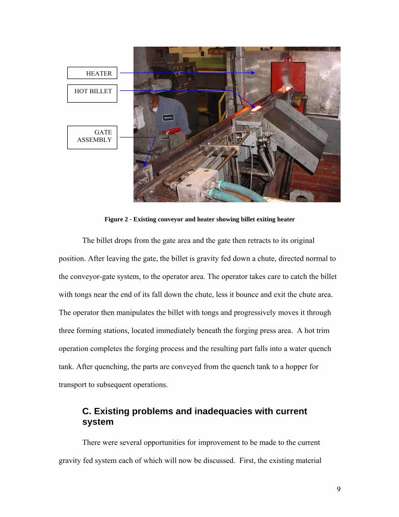
Figure 2 - Existing conveyor and heater showing billet exiting heater
The billet drops from the gate area and the gate then retracts to its original
position. After leaving the gate, the billet is gravity fed down a chute, directed normal to
the conveyor-gate system, to the operator area. The operator takes care to catch the billet
with tongs near the end of its fall down the chute, less it bounce and exit the chute area.
The operator then manipulates the billet with tongs and progressively moves it through
three forming stations, located immediately beneath the forging press area. A hot trim
operation completes the forging process and the resulting part falls into a water quench
tank. After quenching, the parts are conveyed from the quench tank to a hopper for
transport to subsequent operations.
C. Existing problems and inadequacies with current system
There were several opportunities for improvement to be made to the current
gravity fed system each of which will now be discussed. First, the existing material
HEATER
HOT BILLET
GATE ASSEMBLY

10
handling design used a gravity fed chute to deliver the billet from the conveyer system to
the operator area for further processing. As a result of the current system layout, there is
a 26-inch vertical drop from the conveyor system to the operator area. A free fall of about
4 inches occurred before the billet hit a diverter chute (see Figure 3).
Figure 3 - Forging press cross-section
When the part hit the diverter chute, the intent was for it to slide down and be contained
within a small bin at the bottom of the chute. However, in practice, the free fall and
subsequent chute impact process often caused the part to begin to tumble and spin
uncontrollably as it travels down the chute, resulting in erratic and random part location
in the operator “pickup” area.
Second, the gravity fed chute did not consistently deliver the parts to a predictable
location in the operator “pickup” area nor did it consistently orient parts in any particular
manner. This forced the operator to anticipate the fall of the part, and then try to guide the
tumbling billet with tongs in order to consistently move it to the end of the chute into the
11
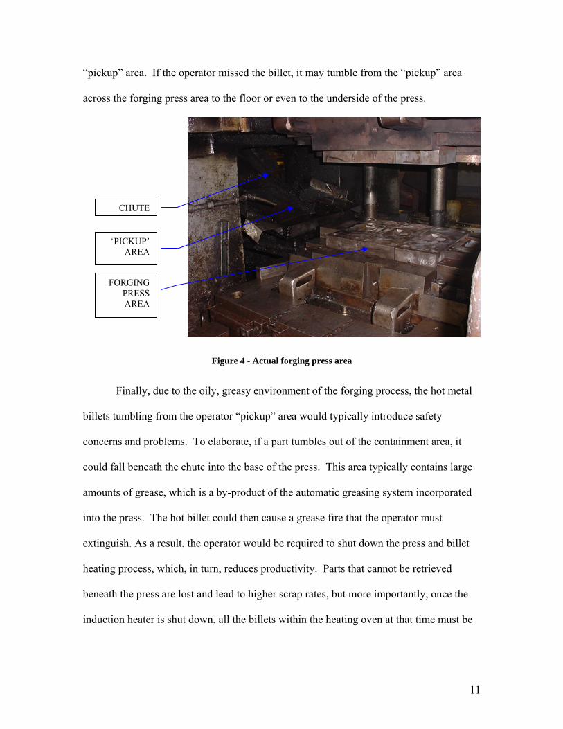
“pickup” area. If the operator missed the billet, it may tumble from the “pickup” area
across the forging press area to the floor or even to the underside of the press.
Figure 4 - Actual forging press area
Finally, due to the oily, greasy environment of the forging process, the hot metal
billets tumbling from the operator “pickup” area would typically introduce safety
concerns and problems. To elaborate, if a part tumbles out of the containment area, it
could fall beneath the chute into the base of the press. This area typically contains large
amounts of grease, which is a by-product of the automatic greasing system incorporated
into the press. The hot billet could then cause a grease fire that the operator must
extinguish. As a result, the operator would be required to shut down the press and billet
heating process, which, in turn, reduces productivity. Parts that cannot be retrieved
beneath the press are lost and lead to higher scrap rates, but more importantly, once the
induction heater is shut down, all the billets within the heating oven at that time must be
CHUTE
‘PICKUP’ AREA
FORGING PRESS AREA

12
purged and the entire forging process restarted. This clearly wastes time, energy and
resources, in addition to causing undue operator stress, and fatigue, and even injury.

13
VI. Project Objectives
The purpose of this project was to re-design, and build a material handling system
that would transport hot stainless steel billets from an induction heater to a forging press.
The process must move billets of various sizes from the induction heater conveyor to the
operator ‘pickup’ area in a reliable and repeatable manner. The design of the system
must be extremely reliable with low maintenance and repair costs. Functionality of the
system is of paramount importance and visual aesthetics need not be considered for this
design. As always, cost is critical to the project, but a more significant upfront
investment would be considered if the design stresses robustness and reliability. The
design must meet certain size and weight constraints. The overall size of the system will
be limited to the opening into the press, which is an area 24 inches wide by 18 inches
high. In addition, the weight constraint requires that no one part can be more than 65 lbs.
such that one person is capable of assembling, repairing and maintaining the new system.
In short, it must be light and compact enough for the maintenance person to install and
remove it from the press area.

14
VII. Impact of Design
A successful redesign will address the billet control issue. Billets will be
transported from the conveyor to the ‘pickup’ area in a repeatable, safe manner, while in
turn, solving the problem of billets tumbling from the operator ‘pickup’ area to the
underside of the press and starting grease fires. By solving the issue of billets being lost
beneath the press, the scrap issue associated with said billets will be addressed as well.
The establishment of repeatable placement will ultimately improve productivity and
increase safety while decreasing operator fatigue and overall stress.
Impaction Company has made available funds to purchase necessary components
required of the new design, and will provide basic tool room machinery to assist in the
fabrication of components not available for purchase. Management, engineering, and
maintenance associates will also be available to provide technical assistance and advice
to the design team.

15
VIII. Detailed Project Description
The existing forging press layout and conveyor constrained the overall size and
layout of the design. Due to the extremely tight and inflexible constraints as shown in
Figure 3, early initial design concepts, considered by the team, which utilized a “straight”
line approach, whereby the billet would travel directly from billet conveyor to operator
pickup area, were disregarded. As a result, the initial design concept chosen for this
project focused on compact billet transfer that is controlled and reliable. It was also
concluded that at each stage of the material movement, the location of the billet must be
known. Therefore, proximity switches, have been incorporated at the defined billet
transfer location and is then integrated within the existing programmable logic controller
that regulates the operation of the press.
The initial concept required the hot billet to travel on the existing conveyor from
the induction heater into an escapement gate where it was captured. At this location the
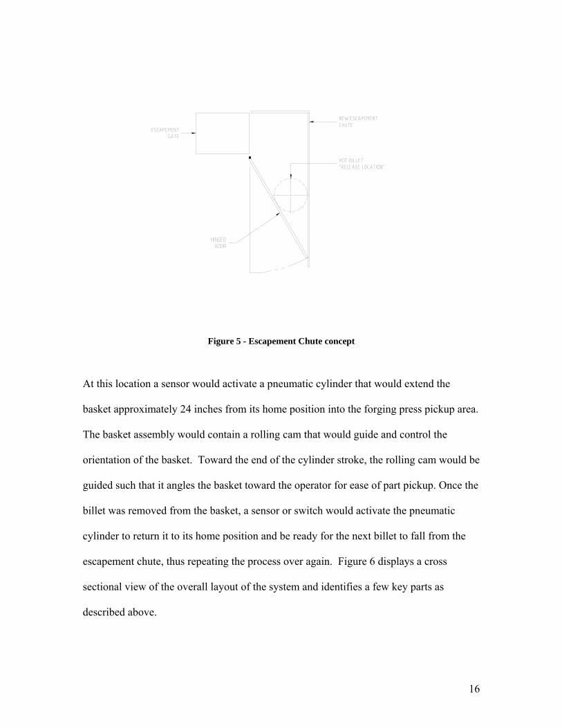
billet is fed into fabricated steel chute, which diverted the billet to fall downward. The
steel escapement chute consists of sheet metal that will contain the billet on all sides with
a hinged door located at the bottom, which is mounted at an angle trapping the cylindrical
billet into a “release” location (see Figure 5). A control cylinder (not shown), connected
to the hinged door, will release the billet from the chute and into a basket in a controlled
manner.
16
Figure 5 - Escapement Chute concept
At this location a sensor would activate a pneumatic cylinder that would extend the
basket approximately 24 inches from its home position into the forging press pickup area.
The basket assembly would contain a rolling cam that would guide and control the
orientation of the basket. Toward the end of the cylinder stroke, the rolling cam would be
guided such that it angles the basket toward the operator for ease of part pickup. Once the
billet was removed from the basket, a sensor or switch would activate the pneumatic
cylinder to return it to its home position and be ready for the next billet to fall from the
escapement chute, thus repeating the process over again. Figure 6 displays a cross
sectional view of the overall layout of the system and identifies a few key parts as
described above.

17
Figure 6 - Overall system layout – Concept #2
A. Timeline
The timeline for this project (see Figure 7) will be monitored and followed to
ensure the project is completed in a timely manner. Microsoft Project is being utilized to
identify major milestones and to track the timelines of action items/task necessary to
complete this project. Each team member has been assigned to the various tasks and this
can be seen within the attached Gantt chart. The overall timeline is broken down into
four major sections. Each section will be discussed below.

18
Figure 7 - Project Gantt chart
19
1. Project Initiation
The project initiation required the design team to perform an on
site visit at Swagelok Company to investigate the company’s needs and
concerns. Once this was performed and the problem was identified, an
initial “brainstorming” session took place to discuss possible design
solutions with all the members of the team. From this “brainstorming”
session, positive and negative aspects for each concept were determined
and a final concept was agreed upon. All of the tasks for this portion of
the timeline, including a mid-term report were completed on schedule.
2. Project Design & Analysis
The design and analysis portion of this project began on October
21, 2005 and was scheduled to be complete by January 31, 2006. Eight
tasks define this portion of the project. The first few related tasks, Design
the System Layout and Design motor and guide track were to be
completed by October 29, 2005 and November 24, 2005 respectively.
These tasks were not completed on time due to the initial design layout
created from early concepts drawings. The early concept drawing
required the pneumatic cylinder and part basket to be mounted at a very
large angle. Interference between the part basket and the forging press
were found when verifying our layout drawings with the existing forging
press drawings. This required the cylinder and guide track to be mounted
at a smaller angle thus lowering and ultimately avoiding the top portion of

20
the part basket from interfering with the forging press during operation.
As a result, designing the system layout, motor and guide track, consumed
more time than initially estimated.
The system layout was then presented to Swagelok executives for
approval. The design was highly criticized for its unnecessary complexity
and it was requested that we eliminate and or modify a few areas to
simplify the overall system. The first area of concern was the billet cart.
There was much concern whether the operator would be able to use tongs
to remove small billets from the cart. This was a major source of concern
since the operator is required to perform the forging operations on the
billet as quickly as possible. The cart, therefore, was viewed as a handicap
in allowing the operator to perform his duties effectively. In addition, the
cart was to be powered by a long (custom) pneumatic cylinder. Swagelok
management viewed this long cylinder as an expensive item should it ever
have to be replaced. This was considered unacceptable, and it was
suggested that we investigate a simplified concept to transport the billet to
the operator pickup area.
As a result of the meeting a new concept was created that
employed previous details such as the escapement chute while building on
the need for a simplified design.
The analysis of the system was scheduled to begin the week of
December 30th and as a result of the design review meeting with
Swagelok, this portion of the project had slipped to the middle of March.

21
3. Project Fabrication and Assembly
Project fabrication and assembly was scheduled to begin April 1,
2006. The design of the escapement chute along with the door mechanism
required the most development work before print details could begin.
Detail drawings such as mounting brackets for the slide tray and the riser
blocks for the pneumatic cylinder were completed first in order to begin
the fabrication process. Work continued during the fabrication and
assembly process to insure that the system mechanical parts work
correctly.
4. System Assembly / Acceptance Test Plan
The system assembly was scheduled to begin in late April,
however, due to unanticipated time constraints, and the unavailability of
the forging press to non-employees, the assembly has not taken place and
Swagelok will be taking on this responsibility. The assembly of the entire
system onto the forging press must minimize the duration of downtime
and may require the system to be put together in various sub-assemblies,
to avoid interruption of Swagelok production as much as possible. In
parallel with this process, Swagelok will be required to create an
acceptance test plan. The acceptance test plan will include various
performance tests to verify that overall system will work safely and
reliably. These tests were to be performed during the week of May 25,
2006.

22
B. Breakdown of Sub-Projects
The design of the material handling delivery system described above, and any
necessary modifications required to the existing equipment were broken down into four
major sub-projects. Each sub-project is discussed in detail below.
1. Escapement chute design
As stated above, the design required the escapement chute to
deliver a billet into the basket in a controlled manner. This would be
achieved through the use of a pneumatic cylinder that would control
and/or dampen the hinged release door. This would maximize the amount
of time in which the billet is simultaneously in contact with the chute wall
and hinged door. In turn this would minimize the distance that the billet
must fall into the basket. A dynamic analysis had been performed to
optimize the required angle of the hinged door such that the release action
is workable over the entire range and size of billets that are manufactured
on the forging press. More detail of the analysis is provided in Section IX,
however, it was determined that the damper design would not
accommodate the full range of billet sizes due to the fact that it would rely
heavily on having a consistent weight. Therefore, a pneumatic cylinder
was utilized. Linkage was also required and was added to accommodate
clearance constraints of the existing design.

23
2. Basket design
The original basket that the billet was to be “placed” into was to be
designed such that it would not only carry the wide range of billet sizes,
but also be robust enough to withstand the apparent heat transfer. Initial
design concepts resulted in an angle type of basket, which utilized a two-
point contact as previously described in the escapement chute design. The
two-point contact would have maximized the holding capability for a wide
range of sizes, while minimizing the amount of surface area contact,
which ultimately would have affected the heat transfer and possible basket
warping. As mentioned early this concept was unacceptable and it was
determined that a simplified gravity fed tray would be sufficient to transfer
the hot billet to the operator pickup area.
3. Gravity fed tray
The original basket was replaced with a gravity fed tray. The tray
was mounted on a 15 degree angle that would slope toward the operator.
The billet would then move under its own power toward the operator. The
tray is designed to be wide enough to handle all billet sizes and
incorporates a “catch” bin at the bottom portion. The “catch” bin was
mounted such that it slopes toward the operator and would only be wide
enough for the largest billet. This is to insure that the billet does not roll
around once it has reached the operator pickup area.

24
4. Controls and PLC integration design
The entire design and control must be integrated with the existing
PLC controller. This is important because the delivery and control of the
billet from the conveyor to the pickup area must be repeatable and
reliable. To achieve this, our design utilizes existing proximity sensor that
switch on delay. The ladder logic is shown in Figure 8 below.
Figure 8 - Electric schematic
Once the billet passes the main proximity switch, a timer is
engaged to activate a solenoid in 3 seconds. This solenoid activates then

25
activates the pneumatic cylinder, forcing the door to open. There are flow
control valves on both the inlet and outlet port of the cylinder to control
the speed at which the door is opened or closed. This can be seen in the
Figure 9 below.
Figure 9 - Pneumatic schematic
The main reason for this design was that it utilized the existing
proximity sensor and avoided the need to introduce “new” unproven
technology. This resulted in a simpler system which is easily
maintainable. Should there be a logic change that needs to occur,
additional sensors could be added with minimal program changes.

26
C. Cost / Return on Investment
The estimated cost for this project is based on the major components that are
necessary to build, manufacture and assemble the system. Figure 10 is a tabulated chart
identifying these key components and the associated costs.
Part Description Part Number CostOuter Guard 2006001 $325.00Rear Guard 2006002 $250.00Door, Weldment 2006003 $150.00Hinge, Continuous 2006004 $25.00Cylinder Foot mount 6471K41 $5.00Main Link 2006007 $50.00Cylinder Spacer 2006008 $80.00Slide Weldment / Fabrication 2006009 $400.00Shaft for Door 2006010 $35.00Clevis for Cylinder 6471K61 $8.00Mounting Plate 2006012 $80.00Side Mounting plate 2006013 $50.00Miscellaneous attachment parts 10000 --> 10013 $75.00
Part Description Part Number Cost5 way, 2 position Control Valve W7016A2331 $168.00Flow Control Valve 1/4" NPT 45045K42 $31.00Pressure Regulator 4957K53 $97.00Air Cylinder (3" stroke) 6471K11 $28.00
Part Description Part Number CostControl Relay 69585K85 $20.00Relay Socket 69585K4 $15.00(ON) Delay on Make Relay 7268K23 $45.00(OFF) Delay on Make Relay 7268K43 $50.00Relay Mounting Socket (8-Pin) 7122K19 $8.0035mm Din Rail 8961K15 $5.00100' 18G Stranded Wire 7587K54 $18.00
Activity Per Hour Cost Cost20 40 $800.00
Total $2,818.00
Mechanical Material List
Pneumatic Material List
Electrical Material List
Labor Hours
Figure 10 - Estimated costs
27
Utilizing current downtime records it is clear there is tremendous inefficiency
with the current system. The current system, which is running three shifts per day and six
days per week, experiences approximately 6 miss-feeds to the operator pickup area per
shift. It requires approximately 5 minutes of time to correct for each miss-feed. Over the
span of one week this equals approximately 7.5 hours of lost productivity. When
multiplied by the current hourly wage of $150, there is a loss of $1,125 per week.
The new design will eliminate this downtime to correct for each miss-feed made
to the operator pickup area. With a total investment of $2,818, the system will have a
repayment time of approximately 2 ½ weeks. More importantly, the new system will
produce a yearly savings of approximately $56,250.

28
IX. Analysis and Modeling
There are two major areas of the material handling delivery system, which need to
be analyzed to optimize its performance and function. Each area will be discussed in
detail below.
1. Chute door Kinematic analysis
Early concepts of the escapement chute door relied upon a damper
cylinder. As result, the chute door would depend heavily on the specific
size of billet and the mounting angle, θ, as well as the angular
acceleration, α, and angular velocity, ω. To optimize the function of the
door our analysis determined the angular velocity and angular acceleration
as a function of the mounting angle, θ. The resulting information was to
assist in sizing the proper cylinder and its final location. The analysis was
performed symbolically and is detailed below. Refer to Figure 11, which
displays the schematic drawing utilized to perform this analysis.

29
Figure 11 - Schematic drawing for analysis
The position equation is defined as,
)(cot* θax = Eqn. 1.
Performing the time derivative of the above equation yields,
dtda
dtdx θθθ )(csc2−= Eqn. 2.
Noting that
ovdtdx
= Eqn. 3.
and
ωθ−=
dtd Eqn. 4.
Substituting equations 3 and 4 into equation 2 will yield,
))((csc2 ωθ −−= avo Eqn. 5.

30
Rearranging equation 5 results in the angular velocity of the door defined
as,
)(csc2 θω
avo= Eqn. 6.
or,
)(sin 2 θωavo= Eqn. 7.
The angular acceleration is performed in a similar manner. From equation
6,
θωα
dd
= Eqn. 8.
Expanding and substituting yields,
dtd
avo θθθα )))(cos)(sin2((= Eqn. 9.
Noting that,
θθθ 2sincossin2 = and θθω 2sinav
dtd o==
substituting results in the angular acceleration of the door defined as,
⎟⎟⎠
⎞⎜⎜⎝
⎛= θθα 2sin2sin
av
av oo Eqn. 10.
or,
θθα 22
2sin2sin
avo= Eqn. 11.
Equation 7 and equation 11 will now be utilized to calculate the
velocity and accelerations for specific mounting angles of the trap door.
This process is ongoing and will continue as described and noted in the
project Gantt chart.

31
We did not use these results as they proved unrealistic for all
ranges of billet sizes. Therefore, the decision was made to control the
door pneumatically. Due to space constraints we determined the position
of the pneumatic cylinder and the location of the chute door was already
known. Therefore, the required linkage was determined graphically and is
shown in Figure 12. The graphical linkage synthesis also confirms that
the escapement door will function properly. Position one which is the
initial position is shown in black while position two is shown in red.
Figure 12 - Graphical Linkage Analysis

32
2. Chute door thermal analysis
In addition to the linkage design it was necessary to account for the
extreme temperatures in which the door would experience. To avoid
possible warping of the door, an insulator was added and fastened to the
inside of the door. To solve this issue, the design required a material with
a low value of thermal conductivity. This was found using alumina board,
a non-brittle material. It has a thermal conductivity value of 1.2 Btu-in/hr-
ft2 F and is able to work within a temperature range of -120 F to +2700 F.
Adding a ¼” thick piece as shown in Figure 13, a few heat transfer
calculations can be determine the amount of heat the steel hinged door
would experience.

33
Figure 13 - Thermal insulation
Assuming a steady state condition as the worse case situation, as opposed
to the transient analysis, the following relationship applies,
xTkAq∆∆
=
Substituting the appropriate values in SI units, results in,
00635.)381260(
)(000645)(.46.2(−
=q
This assumes a very small area of contact due to the door making a
tangential contact with the hot billet. The result is 306 Watts of heat
transferred to the door. This is considerable less than what the hinged
door would experience without insulation and as a result, it should
prevents the hinged door from warping over time.

34
To account for the radiate effect the escapement chute will be
manufactured out of expanded metal to minimize the amount of heat
trapped within the chute area.

35
X. Summary
As stated in the beginning of this report, this design project examined and solved
a manufacturing process problem which was costing the Swagelok Corporation time,
money, and most importantly, the safety of its workers. It involved examining the
current system, which was found to be extremely inadequate, from an entirely different
perspective and conceptualizing a new solution which introduced control and reliability.
This system was then revised and improved upon through collaboration until the final
design was achieved. The result was an extremely simple system which is not only cost
effective to implement, but improved the safety and dependability of the overall system.
The return on this investment will not only allow the employees to become more
productive, but will experience a net savings of approximately $56,000. Overall, it is
clear that this design project has been a success.

36
XI. Appendix A
This portion of the report includes the assembly and detail drawing used to obtain
quotes for fabrication and assembly.
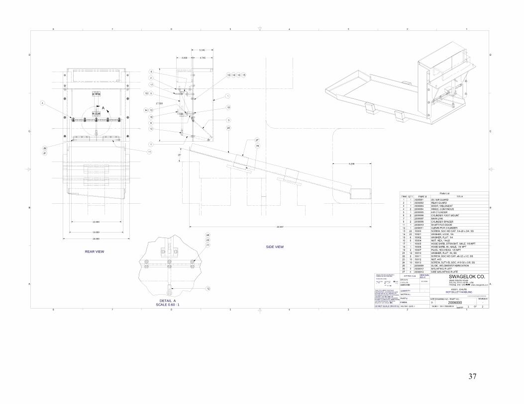
37
ASSY, CHUTE
20060001 2
-
K.GOLLON3/11/2006
D
C:\Kevin\Sc hool\Swagelok\2006000.idw
HOT BILLET HANDLING-
REAR VIEW
SIDE VIEW
16.000
13.000
12.000
17.500
4.000 4.745
5.245
9.298
43.637
15°
DETAIL ASCALE 0.60 : 1

38
OUTER GUARD
20060011 2
-
K.GOLLON 2/10/2006
K.GOLLON
C
C:\Kevin\School\Swagelok\2006001.idw
BILLET MATERIAL HANDLINGSteel, Mild
1
SCALE 3 / 8
13.761
16.000
0.440 15.120
16.63617.500
1.250
4.500
4.500
0.750
2.500
0.266 THRU
0.745
0.120
4.745
4.865
90°
4.125
5.245 90°

39
REAR GUARD
20060021 1
-
K.GOLLON 2/10/2006
C
C:\Kevin\School\Swagelok\2006002.idw
BILLET MATERIAL HANDLING1
12.630
0.120
90°
4.000
3.000
6.391
6.120
0.500
0.500
5.255
1.250
4.500
4.500
7.250 1.500
6.658
4.673
2.000 TYP.0.250 TYP.
R0.120RELIEF
0.281 THRU
0.266 THRU
NOTE:ALL WELDS TO BE SNAG GROUNDBY VENDOR
R-MIN
8.000
2.750 2.750
6.500
7.560
0.201 THRU
0.215

40
DOOR, WELDMENT
20060031 1
-
K.GOLLON 3/14/2006
C
C:\Kevin\School\Swagelok\2006003.idw
BILLET MATERIAL HANDLING1
6.250
0.120
0.5004.0000.500 4.000
12.000 1.370
1.000
1.25090°
0.120
2.000 1.250 TYP.0.250
1.000
0.250
0.257 THRU
0.5004.000
0.250 THRU
0.500
6.000 2.750 2.7500.201 THRU
0.215

41
1
1
2
2
3
3
4
4
A A
B B
C C
D D
SIZE DRAWING NO. / PART NO. REVISION
SCALE: SEE DRAWINGSHEET
OF
DRAWN
CHECKED
UNLESS OTHERWISE SPECIFIEDDIMENSIONS ARE IN INCHES: TOLERANCES ARE: FRACTIONS DECIMALS ANGLES
1/64 .xx .01 1/ 2 .xxx
MATERIAL:
FINISH:
THIS DOCUMENT CONTAINS PROPRIETARY INFORMATION AND DESIGN RIGHTS BELONGING TO SWAGELOK AND/OR ITS SUPPLIERS AND MAY NOT BE USED OR REPRODUCED FOR ANY REASONS EXCEPT CALIBRATION, OPERATIONS AND MAINTENANCE, WITHOUT SPECIFIC AUTHORIZATION.
QUANTITY
DO NOT SCALE DRAWING
PART #:
WEIGHT (LBS.):
SWAGELOK CO.29500 SOLON ROADSOLON, OHIO 44139 - USAPHONE: 440 / 349-5855 www.swagelok.com
APPROVALS ORIGINALISSUE
HINGE, CONTINOUS
20060041 1
-
K.GOLLON 2/21/2002
2/22/2002
C
C:\Kevin\School\Swagelok\2006004.idw
BILLET MATERIAL HANDLINGSteel, Mild
2
12.000
0.500 2.750 2.750 2.750 2.750
0.190
0.201 THRU
0.531
0.040
0.618

42
MAIN LINK
20060071 1
-
K.GOLLON 3/14/2006
C
C:\Kevin\School\Swagelok\2006007.idw
BILLET MATERIAL HANDLINGSteel, Mild
1
0.125
0.500
6.500
7.000
Ø0.250
R0.250
43
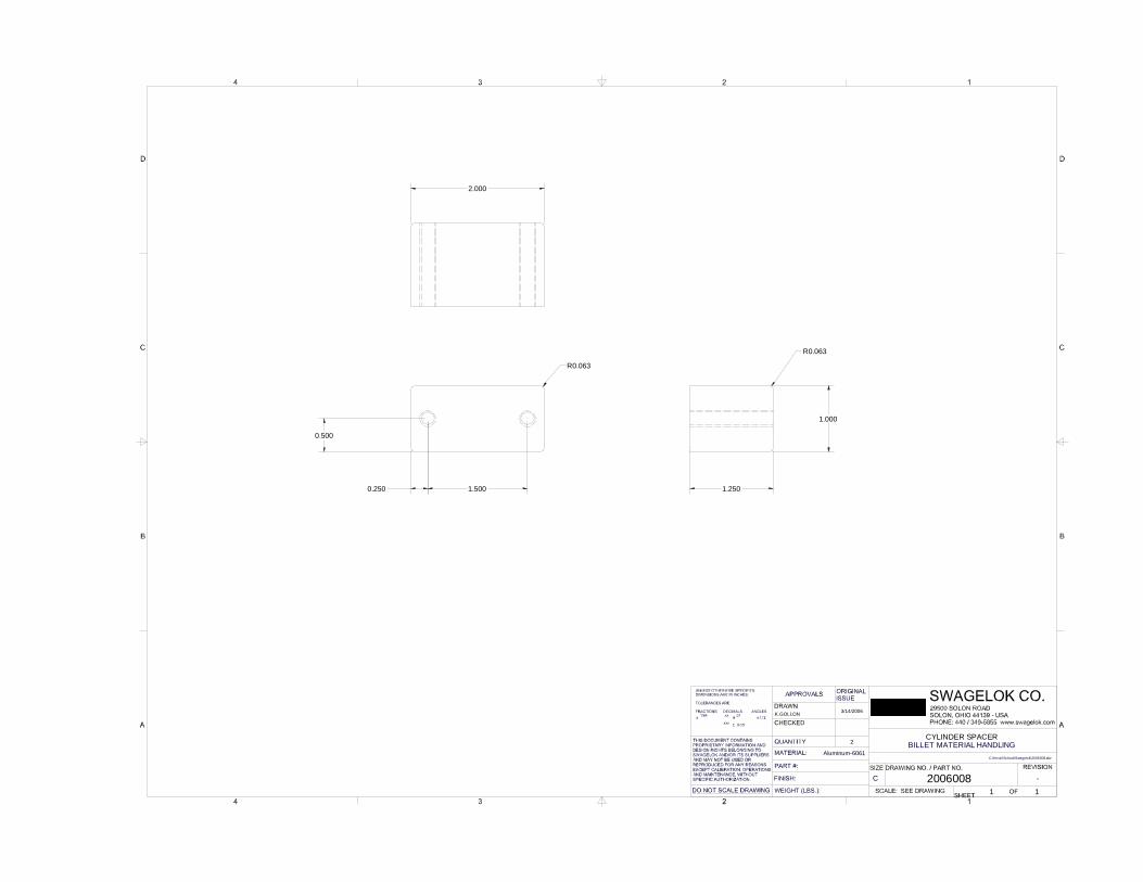
CYLINDER SPACER
20060081 1
-
K.GOLLON 3/14/2006
C
C:\Kevin\School\Swagelok\2006008.idw
BILLET MATERIAL HANDLINGAluminum-6061
2
2.000
1.250
1.000
R0.063
0.250 1.500
0.500
R0.063
44
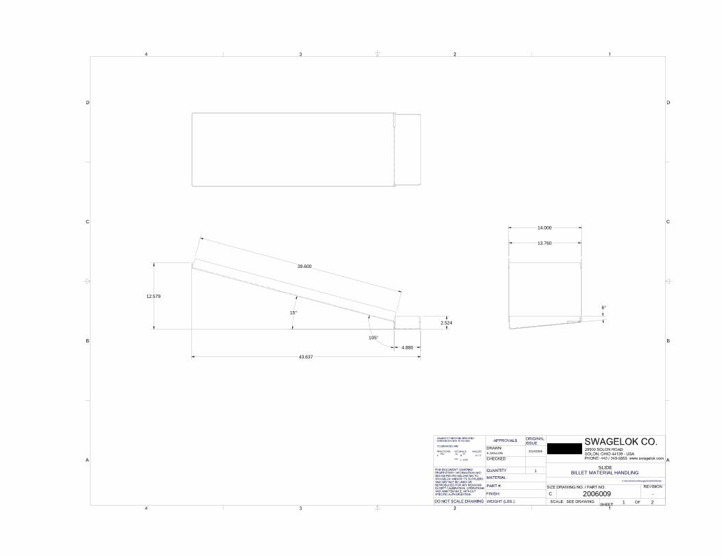
SLIDE
20060091 2
-
K.GOLLON 3/14/2006
C
C:\Kevin\School\Swagelok\2006009.idw
BILLET MATERIAL HANDLING1
43.637
15°
39.600
6°
13.760
14.000
105°
4.880
2.524
12.579

45
1
1
2
2
3
3
4
4
A A
B B
C C
D D
SIZE DRAWING NO. / PART NO. REVISION
SCALE: SEE DRAWINGSHEET OF
DRAWN
CHECKED
UNLESS OTHERWISE SPECIFIEDDIMENSIONS ARE IN INCHES: TOLERANCES ARE: FRACTIONS DECIMALS ANGLES
1/64 .xx .01 1/ 2 .xxx
MATERIAL:
FINISH:
THIS DOCUMENT CONTAINS PROPRIETARY INFORMATION AND DESIGN RIGHTS BELONGING TO SWAGELOK AND/OR ITS SUPPLIERS AND MAY NOT BE USED OR REPRODUCED FOR ANY REASONS EXCEPT CALIBRATION, OPERATIONS AND MAINTENANCE, WITHOUT SPECIFIC AUTHORIZATION.
QUANTITY
DO NOT SCALE DRAWING
PART #:
WEIGHT (LBS.):
SWAGELOK CO.29500 SOLON ROADSOLON, OHIO 44139 - USAPHONE: 440 / 349-5855 www.swagelok.com
APPROVALS ORIGINALISSUE
SHAFT FOR DOOR
20060101 1
-
K.GOLLON 3/14/2006
C
C:\Kevin\School\Swagelok\2006010.idw
BILLET MATERIAL HANDLINGStainless Steel, 440C
1
11.000 Ø0.250
8-32 UNC - 2B ⌧ 0.500FARSIDE ALSO