Embed Size (px)
Citation preview

A N A M E R I C A N N A T I O N A L S T A N D A R D
ASME B16.11-2016(Revision of ASME B16.11-2011)
Forged Fittings, Socket-Welding and Threaded
falatghareh.irfalatghareh.ir

ASME B16.11-2016(Revision of ASME B16.11-2011)
Forged Fittings,Socket-Weldingand Threaded
AN AMERICAN NATIONAL STANDARD
falatghareh.irfalatghareh.ir

Date of Issuance: January 20, 2017
The next edition of this Standard is scheduled for publication in 2021.
ASME issues written replies to inquiries concerning interpretations of technical aspects of this Standard. Periodically certainactions of the ASME B16 Committeemay be published as Cases. Cases and interpretations are published on the ASMEWeb siteunder the Committee Pages at http://cstools.asme.org/ as they are issued.
Errata to codes and standards may be posted on the ASME Web site under the Committee Pages to provide corrections toincorrectly published items, or to correct typographical or grammatical errors in codes and standards. Such errata shall be usedon the date posted.
The Committee Pages can be found at http://cstools.asme.org/. There is an option available to automatically receive an e-mailnotification when errata are posted to a particular code or standard. This option can be found on the appropriate CommitteePage after selecting “Errata” in the “Publication Information” section.
ASME is the registered trademark of The American Society of Mechanical Engineers.
This code or standardwas developed under procedures accredited asmeeting the criteria for American National Standards. The StandardsCommittee that approved the code or standardwas balanced to assure that individuals from competent and concerned interests have had anopportunity to participate. The proposed code or standard was made available for public review and comment that provides an opportunityfor additional public input from industry, academia, regulatory agencies, and the public-at-large.
ASME does not “approve,” “rate,” or “endorse” any item, construction, proprietary device, or activity.ASME does not take any position with respect to the validity of any patent rights asserted in connection with any items mentioned in this
document, and does not undertake to insure anyone utilizing a standard against liability for infringement of any applicable letters patent, norassumesany such liability.Usersof a codeor standardareexpressly advised thatdeterminationof thevalidityof any suchpatent rights, and therisk of infringement of such rights, is entirely their own responsibility.
Participation by federal agency representative(s) or person(s) affiliated with industry is not to be interpreted as government or industryendorsement of this code or standard.
ASME accepts responsibility for only those interpretations of this document issued in accordance with the established ASME proceduresand policies, which precludes the issuance of interpretations by individuals.
No part of this document may be reproduced in any form,in an electronic retrieval system or otherwise,
without the prior written permission of the publisher.
The American Society of Mechanical EngineersTwo Park Avenue, New York, NY 10016-5990
Copyright © 2017 byTHE AMERICAN SOCIETY OF MECHANICAL ENGINEERS
All rights reservedPrinted in U.S.A.
falatghareh.irfalatghareh.ir

CONTENTS
Foreword . . . . . . . . . . . . . . . . . . . . . . . . . . . . . . . . . . . . . . . . . . . . . . . . . . . . . . . . . . . . . . . . . . . . . . . . v
Committee Roster . . . . . . . . . . . . . . . . . . . . . . . . . . . . . . . . . . . . . . . . . . . . . . . . . . . . . . . . . . . . . . . . . . vii
Correspondence With the B16 Committee . . . . . . . . . . . . . . . . . . . . . . . . . . . . . . . . . . . . . . . . . . . . . . . . . viii
Summary of Changes . . . . . . . . . . . . . . . . . . . . . . . . . . . . . . . . . . . . . . . . . . . . . . . . . . . . . . . . . . . . . . . . x
List of Changes in Record Number Order . . . . . . . . . . . . . . . . . . . . . . . . . . . . . . . . . . . . . . . . . . . . . . . . . xii
1 Scope and General . . . . . . . . . . . . . . . . . . . . . . . . . . . . . . . . . . . . . . . . . . . . . . . . . . . . . . . . 12 Pressure Ratings . . . . . . . . . . . . . . . . . . . . . . . . . . . . . . . . . . . . . . . . . . . . . . . . . . . . . . . . . 13 Size and Type . . . . . . . . . . . . . . . . . . . . . . . . . . . . . . . . . . . . . . . . . . . . . . . . . . . . . . . . . . . 84 Marking . . . . . . . . . . . . . . . . . . . . . . . . . . . . . . . . . . . . . . . . . . . . . . . . . . . . . . . . . . . . . . . . 85 Material . . . . . . . . . . . . . . . . . . . . . . . . . . . . . . . . . . . . . . . . . . . . . . . . . . . . . . . . . . . . . . . . 96 Dimensions . . . . . . . . . . . . . . . . . . . . . . . . . . . . . . . . . . . . . . . . . . . . . . . . . . . . . . . . . . . . . 97 Additional Tolerances . . . . . . . . . . . . . . . . . . . . . . . . . . . . . . . . . . . . . . . . . . . . . . . . . . . . . 108 Proof Testing . . . . . . . . . . . . . . . . . . . . . . . . . . . . . . . . . . . . . . . . . . . . . . . . . . . . . . . . . . . . 10
Mandatory AppendicesI Dimensions of Fittings in U.S. Customary Units . . . . . . . . . . . . . . . . . . . . . . . . . . . . . . . . . . . . 11II References . . . . . . . . . . . . . . . . . . . . . . . . . . . . . . . . . . . . . . . . . . . . . . . . . . . . . . . . . . . . . . 18
Nonmandatory AppendicesA Quality System Program . . . . . . . . . . . . . . . . . . . . . . . . . . . . . . . . . . . . . . . . . . . . . . . . . . . . . 19
Figures1 Method of Designating Outlets of Reducing Tees and Crosses . . . . . . . . . . . . . . . . . . . . . . . . . . 92 Welding Gap and Minimum Flat Dimensions for Socket-Welding Fittings . . . . . . . . . . . . . . . . . . 10
Tables1 Socket-Welding Elbows, Tees, and Crosses . . . . . . . . . . . . . . . . . . . . . . . . . . . . . . . . . . . . . . . . 22 Socket-Welding Couplings, Bosses, Caps, and Couplets . . . . . . . . . . . . . . . . . . . . . . . . . . . . . . . 33 Threaded Elbows, Tees, and Crosses . . . . . . . . . . . . . . . . . . . . . . . . . . . . . . . . . . . . . . . . . . . . 44 Threaded Street Elbows . . . . . . . . . . . . . . . . . . . . . . . . . . . . . . . . . . . . . . . . . . . . . . . . . . . . . 55 Threaded Couplings, Bosses, Caps, and Couplets . . . . . . . . . . . . . . . . . . . . . . . . . . . . . . . . . . . 66 Plugs and Bushings . . . . . . . . . . . . . . . . . . . . . . . . . . . . . . . . . . . . . . . . . . . . . . . . . . . . . . . . 77 Types of Fittings by Class Designation and NPS Size Range . . . . . . . . . . . . . . . . . . . . . . . . . . . 88 Correlation of Fittings Class With Schedule Number or Wall Designation of Pipe for Calculation of
Ratings . . . . . . . . . . . . . . . . . . . . . . . . . . . . . . . . . . . . . . . . . . . . . . . . . . . . . . . . . . . . . . . 89 Nominal Wall Thickness of Schedule 160 and Double Extra Strong Pipe . . . . . . . . . . . . . . . . . . 8I-1 Socket-Welding Elbows, Tees, and Crosses . . . . . . . . . . . . . . . . . . . . . . . . . . . . . . . . . . . . . . . . 12I-2 Socket-Welding Couplings, Bosses, Caps, and Couplets . . . . . . . . . . . . . . . . . . . . . . . . . . . . . . . 13
iii
falatghareh.irfalatghareh.ir

I-3 Threaded Elbows, Tees, and Crosses . . . . . . . . . . . . . . . . . . . . . . . . . . . . . . . . . . . . . . . . . . . . 14I-4 Threaded Street Elbows . . . . . . . . . . . . . . . . . . . . . . . . . . . . . . . . . . . . . . . . . . . . . . . . . . . . . 15I-5 Threaded Couplings, Bosses, Caps, and Couplets . . . . . . . . . . . . . . . . . . . . . . . . . . . . . . . . . . . 16I-6 Plugs and Bushings . . . . . . . . . . . . . . . . . . . . . . . . . . . . . . . . . . . . . . . . . . . . . . . . . . . . . . . . 17
iv
falatghareh.irfalatghareh.ir

FOREWORD
The Sectional Committee on the Standardization of Pipe Flanges and Fittings, B16, organized in 1920 under theprocedure of the American Standards Association (ASA), appointed a subgroup of Subcommittee 3 (nowSubcommittee F) to initiate the standardization of welding fittings in May 1937. The first meeting of this groupwas held later that month, and at its meeting in December 1938, in New York, it was agreed to undertake the stan-dardization of dimensions of socket-welding fittings and to refer this project to a new drafting subgroup. One of themostimportant dimensions of this type of fitting requiring standardization was considered to be the dimension from thecenterline of the fitting to the bottom of the socket, since from the standpoint of the designing engineer, this dimensiongoverns the location of adjacent pipewith reference to the entire piping layout. Another important item for considerationwas the welding fillet dimensions.The drafting subgroup held meetings in Chicago, Detroit, and New York in March 1939 and May and October 1940,
respectively, and at the last named meeting, the completed draft of the proposed standard was discussed, and furtherrevisionswere suggested.When applied to the September 1940draft, these changes produced theMay 1941draft, whichwas prepared for distribution to industry for criticism and comment.This distribution resulted in a number of helpful comments. Themembers of the subgroup agreed bymail thatmany of
the changes suggested should be incorporated in the revised draft (December 1941). Progress on the approval of thestandardwas delayed by theWorldWar II, after which, a fewmore changes were added tomake the proposal acceptableto all concerned. The revised draft (April 1946) was then submitted to themembers of the sectional committee for letterballot vote.Following the approval of the sectional committee, the proposed standard was next approved by the sponsor bodies
and presented to the ASA with recommendation for approval as an American Standard. This designation was given onDecember 9, 1946.In 1960, it was agreed that the standard needed a complete revision and simultaneously that it should be expanded to
cover threaded fittings and plugs, then covered by MSS SP-49 and SP-50. A Task Force worked diligently for four yearsbefore arriving at a draft that was acceptable. They also found that ratings were outdated and eliminated the 4,000-lbclasses of threaded fittings, assigned pressure-temperature ratings for a number of materials, and converted the socket-weld fitting ratings to3,000and6,000 lb. Followingapproval by theSectional Committee andSponsors,ASAapprovalwasgranted on January 28, 1966.Following designation changes of ASA to ANSI and Sectional Committee to Standards Committee, Subcommittee 6
began consideration of changes in 1969. Early in 1972, changes in the pressure class designations, materials, and clar-ification of wording were agreed upon and submitted for approval. This was granted on June 20, 1973.The work of development of the 1980 edition of B16.11 began in 1975 when the committee began consideration of
comments and proposals for change that were received. The development procedure was arduous in that a number ofballots were taken that elicited many additional comments and counterproposals. The major changes included anexpanded scope for better definition, requirements for conformance marking, a Nonmandatory Annex with provisionsforprooforburst testing, and the inclusionofmetric equivalents. Followingapproval by theStandardsCommitteeandCo-Secretariat, final approval by ANSI was granted on October 6, 1980.In 1982, American National Standards Committee B16 was reorganized as an ASME Committee operating under
procedures accredited by ANSI. The 1991 edition of the standard, retitled “Forged Fittings, Socket-Welding andThreaded,” incorporated forging material listed in Table 1 of ASME B16.34-1988, including Group 3 material thatwasnot previously covered inB16.11. The1991edition establishedU.S. Customaryunits as the standard. Other clarifyingand editorial revisions were made to improve the text. Following approval by the Standards Committee and ASME, finalapproval by ANSI was granted on March 4, 1991.In 1996, metric dimensionswere added as an independent but equal standard to the inch units. Following approval by
the Standards Committee and ASME, this revision to the 1991 edition of this Standard was approved as an AmericanNational Standard by ANSI on December 16, 1996, with the new designation ASME B16.11-1996.In 2000, the Standards Committee, ASME, and ANSI approved an addenda to this Standard to remove partial compli-
ance fittings and nonstandard material requirements. Due to an ASME policy change concerning the publishing ofaddenda, the intended addenda changes were incorporated into the 2001 edition.
v
falatghareh.irfalatghareh.ir

Threaded end street elbow requirements were incorporated into the 2004 edition. Following approval by theStandards Committee and ASME, the revision to the 2001 edition was approved as an American National Standardby ANSI on September 30, 2005 with the designation ASME B16.11-2005.A number of technical revisions were made along with format and reference revisions, such as material marking
requirements. Following approval by the Standards Committee andASME, the revision to the 2005 editionwas approvedas an American National Standard by ANSI on July 9, 2009 with the designation ASME B16.11-2009.This revision was approved by the American National Standards Institute on December 2, 2011.In this 2016 Edition, provisions have beenmade to update verbiage and readings. Following the approval by the ASME
B16 Standards Committee, approval as an American National Standard was given by ANSI on October 21, 2016, with thenew designation ASME B16.11-2016.
vi
falatghareh.irfalatghareh.ir

ASME B16 COMMITTEEStandardization of Valves, Flanges, Fittings, and Gaskets
(The following is the roster of the Committee at the time of approval of this Standard.)
STANDARDS COMMITTEE OFFICERSR. M. Bojarczuk, ChairC. E. Davila, Vice ChairC. Ramcharran, Secretary
STANDARDS COMMITTEE PERSONNEL
A. Appleton, Alloy Stainless Products Co., Inc.J. E. Baker, Dezurik Water ControlsR. W. Barnes, Anric Enterprises, Inc.P. Milankov, Alternate, Anric Enterprises, Inc.K. Barron, Ward ManufacturingD. C. Bayreuther, Metso Automation, Flow Control DivisionW. B. Bedesem, ConsultantR. M. Bojarczuk, ExxonMobil Research and Engineering Co.A. M. Cheta, Qatar Shell GTLM. A. Clark, Nibco, Inc.P. V. Craig, Jomar GroupG. A. Cuccio, Capitol Manufacturing Co.C. E. Davila, Crane EnergyJ. D’Avanzo, Fluoroseal ValvesB. G. Fabian, Pennsylvania Machine Works
F. Feng, China Productivity Center for MachineryD. R. Frikken, Becht Engineering Co.R. B. Hai, RBH AssociatesG. A. Jolly, Samshin Ltd.M. Katcher, Haynes InternationalA. G. Kireta, Jr., Copper Development Association, Inc.T. A. McMahon, Emerson Process ManagementM. L. Nayyar, NICEW. H. Patrick, The Dow Chemical Co.D. Rahoi, CCM 2000C. Ramcharran, The American Society of Mechanical EngineersD. F. Reid, VSP TechnologiesR. A. Schmidt, CanadoilJ. Tucker, FlowserveF. R. Volgstadt, Volgstadt and Associates, Inc.
SUBCOMMITTEE F — STEEL THREADED AND WELDING FITTINGS
B. G. Fabian, Chair, Pennsylvania Machine WorksR. A. Schmidt, Vice Chair, CanadoilE. Lawson, Secretary, The American Society of Mechanical EngineersA. Appleton, Alloy Stainless Products Co., Inc.G. A. Cuccio, Capitol Manufacturing Co.K. W. Doughty, CB&I Alloy Piping ProductsJ. P. Ellenberger, RetiredD. R. Frikken, Becht Engineering Co.P. W. Heald, Bonny Forge Co.
D. Hunt, Jr., FastenalG. A. Jolly, Samshin LimitedF. Kavarana, CBI Inc.C. J. Lafferty, U.S. Drop Forge Co.W. Pritzl, Erne Fittings GmbHJ. P. Tucker, Flowserve Corp.G. T. Walden, WolseleyM. M. Zaidi, Jacobs Engineering Group, Inc.
vii
falatghareh.irfalatghareh.ir

CORRESPONDENCE WITH THE B16 COMMITTEE
General. ASME Standards are developed and maintained with the intent to represent the consensus of concernedinterests. As such, users of this Standard may interact with the Committee by requesting interpretations, proposingrevisions or a case, and attending Committee meetings. Correspondence should be addressed to:
Secretary, B16 Standards CommitteeThe American Society of Mechanical EngineersTwo Park AvenueNew York, NY 10016-5990http://go.asme.org/Inquiry
Proposing Revisions. Revisions are made periodically to the Standard to incorporate changes that appear necessaryor desirable, as demonstrated by the experience gained from the application of the Standard. Approved revisions will bepublished periodically.The Committee welcomes proposals for revisions to this Standard. Such proposals should be as specific as possible,
citing the paragraph number(s), the proposed wording, and a detailed description of the reasons for the proposal,including any pertinent documentation.
Proposing a Case. Casesmay be issued to provide alternative rules when justified, to permit early implementation ofan approved revision when the need is urgent, or to provide rules not covered by existing provisions. Cases are effectiveimmediately upon ASME approval and shall be posted on the ASME Committee Web page.Requests for Cases shall provide a Statement of Need and Background Information. The request should identify the
Standard and the paragraph, figure, or table number(s), and be written as a Question and Reply in the same format asexisting Cases. Requests for Cases should also indicate the applicable edition(s) of the Standard to which the proposedCase applies.
Interpretations. Upon request, the B16 Standards Committeewill render an interpretation of any requirement of theStandard. Interpretations canonlybe rendered in response to awritten request sent to theSecretaryof theB16StandardsCommittee.Requests for interpretation should preferably be submitted through the online Interpretation Submittal Form. The
form is accessible at http://go.asme.org/InterpretationRequest. Upon submittal of the form, the Inquirer will receive anautomatic e-mail confirming receipt.If the Inquirer is unable to use the online form, he/she may e-mail the request to the Secretary of the B16 Standards
Committee at [email protected], or mail it to the above address. The request for an interpretation should be clearand unambiguous. It is further recommended that the Inquirer submit his/her request in the following format:
Subject: Cite the applicable paragraph number(s) and the topic of the inquiry in one or two words.Edition: Cite the applicable edition of the Standard for which the interpretation is being requested.Question: Phrase the question as a request for an interpretation of a specific requirement suitable for
general understanding and use, not as a request for an approval of a proprietary design orsituation. Please provide a condensed and precise question, composed in such away that a“yes” or “no” reply is acceptable.
Proposed Reply(ies): Provide a proposed reply(ies) in the form of “Yes” or “No,” with explanation as needed. Ifentering replies to more than one question, please number the questions and replies.
Background Information: Provide the Committee with any background information that will assist the Committee inunderstanding the inquiry. The Inquirer may also include any plans or drawings that arenecessary to explain the question; however, they should not contain proprietary names orinformation.
viii
falatghareh.irfalatghareh.ir

Requests that arenot in the format describedabovemaybe rewritten in the appropriate formatby theCommitteepriorto being answered, which may inadvertently change the intent of the original request.ASMEprocedures provide for reconsideration of any interpretationwhen or if additional information thatmight affect
an interpretation is available. Further, persons aggrieved by an interpretation may appeal to the cognizant ASMECommittee or Subcommittee. ASME does not “approve,” “certify,” “rate,” or “endorse” any item, construction, proprietarydevice, or activity.
Attending Committee Meetings. The B16 Standards Committee regularly holds meetings and/or telephone confer-ences that are open to the public. Personswishing to attend anymeeting and/or telephone conference should contact theSecretary of the B16 Standards Committee.
ix
falatghareh.irfalatghareh.ir

ASME B16.11-2016SUMMARY OF CHANGES
Following approval by the ASME B16 Committee and ASME, and after public review, ASME B16.11-2016 was approved by theAmerican National Standards Institute on October 21, 2016.
ASME B16.11-2016 includes the following changes identified by a margin note, (16). The Record Number listed below isexplained in more detail in the “List of Changes in Record Number Order” following this Summary of Changes.
Page Location Change2 Table 1 Title and table revised in its entirety
(12-389)3 Table 2 New Table 2 added; previous Table 2
redesignated as Table 3 and revised in itsentirety (12-389)
4 Table 3 Redesignated as Table 4 and title revised(12-389)
4 2.2 Revised in its entirety (13-632)5 Table 4 (1) Redesignated as Table 5 (12-389)
(2) Title and table revised in its entirety(12-389)
(3) Under Nominal Pipe Size 1∕8, entriesadded for Class 6000 for End-to-End Caps,P, and Minimum End Wall Thickness, G(16–351)
6 Table 5 (1) Redesignated as Table 6 (12-389)(2) Under Nominal Pipe Size 2, entry forMinimumWidth Flats, C, revised (16-351)
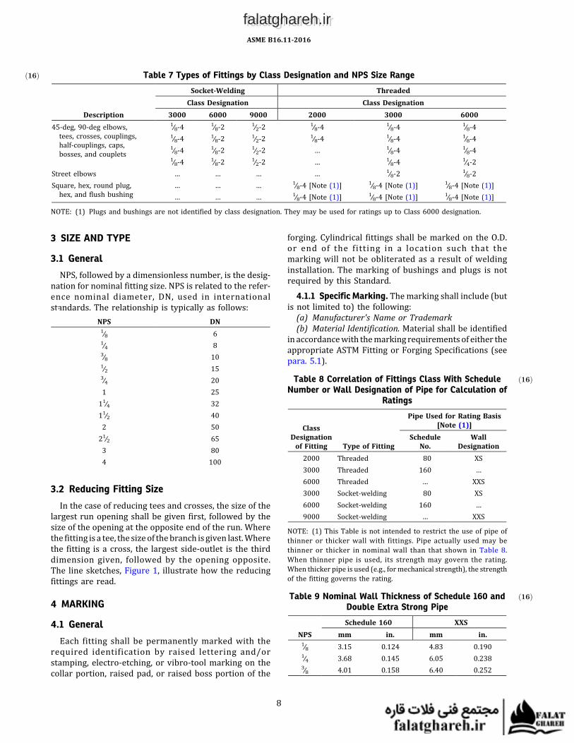
7 Table 6 (1) Redesignated as Table 7 (12-389)(2) First entry under Description revised(16-351)
8 Table 7 Redesignated as Table 8 (12-389)8 Table 8 Redesignated as Table 9 (12-389)8 Table 9 Redesignated from previous Table 8
(12-389)9 5.1 Last sentence revised (15-2823)12 Table I-1 Title and table revised in its entirety
(12-389)13 Table I-2 New Table I-2 added; previous Table I-2
redesignatedasTable I-3 and revised in itsentirety (12-389)
14 Table I-3 Redesignated as Table I-4 (12-389)15 Table I-4 (1) Redesignated as Table I-5 (12-389)
(2) Title and table revised in its entirety(12-389)
x
falatghareh.irfalatghareh.ir

(3) UnderNormal Pipe Size 1∕8, entries addedfor Class 6000 for End-to-End Caps, P, andMinimum End Wall Thickness, G (16-351)
16 Table I-5 Redesignated as Table I-6 (12-389)18 Mandatory Appendix II References updated (16-829)
xi
falatghareh.irfalatghareh.ir

LIST OF CHANGES IN RECORD NUMBER ORDER
Record Number Change12-389 Updated tables inserted throughout document13-632 To clarify and correct para 5.1 in B16.11–2011 language so as to not disallow bar stock as a starting material.15-2823 NPS 1∕8 Class 6000 capdimensions added toTables 5 and I-5, since the Standardhas requirements for outside diameter
dimension listed for NPS 1/8 Class 6000 couplings, half couplings, and caps; and in Table 7 indicates Class 6000couplings and half-couplings are available in NPS 1∕8-4
16-351 Table 5 data16-829 Mandatory Appendix II references updated
xii
falatghareh.irfalatghareh.ir

FORGED FITTINGS, SOCKET-WELDING AND THREADED
1 SCOPE AND GENERAL
1.1 Scope
This Standard covers ratings, dimensions, tolerances,marking, and material requirements for forged fittings,both socket-welding and threaded, as illustrated inTables 1 through 6 and Tables I-1 through I-6, inclusive.
1.1.1 Fitting Types/Configuration. Types of fittingscovered by this Standard are shown in Table 7, byclass and size range. Fittings shown in Tables 1through 6 and Tables I-1 through I-6 may also bemade with combinations of socket-welding and threadedends.
1.1.2 Special Fittings. Fittings with special dimen-sions, threads, or counterbores may be made by agree-ment between the manufacturer and purchaser. Whensuch fittings meet all other stipulations of thisStandard, they shall be considered in compliance there-with, provided they are appropriatelymarked (see section4).
1.1.3 Welding. Installation welding requirements arenot within the scope of this Standard. Installationwelding shall be in accordance with the applicablepiping Code or regulation covering the piping systeminto which the fittings are installed.
1.2 General1.2.1 Referenced Standards. Standards and specifica-
tions adopted by reference in this Standard are shown inMandatory Appendix II. It is not considered practical toidentify the specific edition of each standard and specifi-cation in the individual references. Instead, the specificedition reference is identified in Mandatory AppendixII. A fitting made in conformance and conforming tothis Standard, in all other respects, will be consideredto be in conformance to the Standard, even though theedition referencemaybechanged ina subsequent revisionof the Standard.
1.2.2 Codes and Regulations. A fitting used under thejurisdiction of the ASME Boiler and Pressure Vessel Code,the ASME Code for Pressure Piping, or a governmentalregulation is subject to any limitation of that code or regu-lation. This includes any maximum temperature limita-tion, rule governing the use of a material at lowtemperature, or provisions for operation at a pressureexceeding the ratings in this Standard.
1.2.3 ServiceConditions.Criteria for selectionof fittingtypes andmaterials suitable forparticular fluid servicearenot within the scope of this Standard.
1.2.4 Quality Systems. Nonmandatory requirementsrelating to the product manufacturer's quality systemprogram are described in Nonmandatory Appendix A.
1.2.5 Relevant Units. This Standard states values inboth SI (Metric) and U.S. Customary units. Thesesystemsof units are tobe regardedseparately as standard.Within the text, the U.S. Customary units are shown inparentheses or in separate tables that appear inMandatory Appendix I. The values stated in eachsystem are not exact equivalents; therefore, it is requiredthat each system of units be used independently of theother. Combining values from the two systems constitutesnonconformance with the Standard.Tables 1 through 6 show fittings dimensional require-
ments in millimeters. Tables I-1 through I-6 show thedimensional requirements for inch dimensioned fittings.
2 PRESSURE RATINGS
2.1 General
Fittings under this Standard shall be designated as Class2000, 3000, and 6000 for threaded end fittings and Class3000, 6000, and 9000 for socket-weld end fittings.
2.1.1 Basis of Rating. The schedule of pipe corre-sponding to each Class designation of fitting for ratingpurposes is shown in Table 8. Design temperature andother service conditions shall be limited as providedby theapplicablepipingcodeor regulation for thematerialof construction of the fitting. Within these limits, theminimum wall thickness for pipe to be used with aTable 8 Class designated fitting shall be computedbased on appropriate size straight seamless pipe ofequivalentmaterial as the fitting (as shownbycomparisonof composition and mechanical properties in the respec-tive material specifications). The minimum pipe wallthickness calculation shall include pressure design andall applicable additional allowances (e.g., erosion, corro-sion, and thread depth for threaded pipe). The minimumwall thickness for selected pipe, considering manufac-turing minus wall thickness tolerance (typically12.5%), shall not be less than the minimum wall calcula-tion. The fitting is suitable for the application if the wallthickness of the selected pipe equals or is less than theASME B36.10M Schedule No. or Wall Designation pipewall thickness correlated with the fitting in Table 8[see Note (1) in Table 8].
ASME B16.11-2016
1
falatghareh.irfalatghareh.ir

Table 1ð16Þ Socket-Welding Elbows, Tees, and Crosses
NominalPipeSize
Socket BoreDiam., B
Bore Diameter of Fittings, D Socket Wall Thickness, C [Note (1)] Body Wall, G SocketDepth,
J
Center-to-Bottom of Socket, A
3000 6000 9000 3000 6000 9000 3000 6000 9000 90 El, Cross, Tee 45–deg Elbow TolMax. Min. Max. Min. Max. Min. Max. Min. Avg. Min. Avg. Min. Avg. Min. Min. Min. Min. Min. 3000 6000 9000 3000 6000 9000 ±
1∕8 11.2 10.8 7.6 6.1 4.8 3.2 … … 3.18 3.18 3.96 3.43 … … 2.41 3.15 … 9.5 11.0 11.0 … 8.0 8.0 … 1.01∕4 14.6 14.2 10.0 8.5 7.1 5.6 … … 3.78 3.30 4.60 4.01 … … 3.02 3.68 … 9.5 11.0 13.5 … 8.0 8.0 … 1.03∕8 18.0 17.6 13.3 11.8 9.9 8.4 … … 4.01 3.50 5.03 4.37 … … 3.20 4.01 … 9.5 13.5 15.5 … 8.0 11.0 … 1.51∕2 22.2 21.8 16.6 15.0 12.5 11.0 7.2 5.6 4.67 4.09 5.97 5.18 9.35 8.18 3.73 4.78 7.47 9.5 15.5 19.0 25.5 11.0 12.5 15.5 1.5
3∕4 27.6 27.2 21.7 20.2 16.3 14.8 11.8 10.3 4.90 4.27 6.96 6.04 9.78 8.56 3.91 5.56 7.82 12.5 19.0 22.5 28.5 13.0 14.0 19.0 1.51 34.3 33.9 27.4 25.9 21.5 19.9 16.0 14.4 5.69 4.98 7.92 6.93 11.38 9.96 4.55 6.35 9.09 12.5 22.5 27.0 32.0 14.0 17.5 20.5 2.011∕4 43.1 42.7 35.8 34.3 30.2 28.7 23.5 22.0 6.07 5.28 7.92 6.93 12.14 10.62 4.85 6.35 9.70 12.5 27.0 32.0 35.0 17.5 20.5 22.5 2.011∕2 49.2 48.8 41.6 40.1 34.7 33.2 28.7 27.2 6.35 5.54 8.92 7.80 12.70 11.12 5.08 7.14 10.15 12.5 32.0 38.0 38.0 20.5 25.5 25.5 2.0
2 61.7 61.2 53.3 51.7 43.6 42.1 38.9 37.4 6.93 6.04 10.92 9.50 13.84 12.12 5.54 8.74 11.07 16.0 38.0 41.0 54.0 25.5 28.5 28.5 2.021∕2 74.4 73.9 64.2 61.2 … … … … 8.76 7.67 … … … … 7.01 … … 16.0 41.0 … … 28.5 … … 2.53 90.3 89.8 79.4 76.4 … … … … 9.52 8.30 … … … … 7.62 … … 16.0 57.0 … … 32.0 … … 2.54 115.7 115.2 103.8 100.7 … … … … 10.69 9.35 … … … … 8.56 … … 19.0 66.5 … … 41.0 … … 2.5
GENERAL NOTE: Dimensions are in millimeters.
NOTE: (1) Average of socket wall thickness around periphery shall not be less than listed values. The minimum values are permitted in localized areas.
ASMEB16.11-2016
2
falatghareh.irfalatghareh.ir

Table 2ð16Þ Socket-Welding Couplings, Bosses, Caps, and Couplets
NominalPipeSize
SocketBoreDia., B
Bore Diameter of Fittings, D Socket Wall Thickness, [Note (1)], COutsideDia.
Couplet,G Tol.
SocketDepth, J
LayingLgth., E Tol.
LayingLgth., F Tol.
End WallThickness, K
End to EndCouplet, M
Weld RingDiameter, N
WeldRingLength,
Q Tol.3000 6000 9000 3000 6000 9000 3000 6000 9000 Tol. Tol.
Max. Min. Max. Min. Max. Min. Max. Min. Avg. Min. Avg. Min. Avg. Min. 3000 6000 ± Min. ± ± Min. Min. Min. ± ±3000/6000 ±
1∕8 11.2 10.8 7.6 6.1 4.8 3.2 … … 3.18 3.18 3.96 3.43 … … … … ±1.5/−0.0 9.5 6.5 1.5 16.0 1.5 4.8 6.4 … … … … … … …1∕4 14.6 14.2 10.0 8.5 7.1 5.6 … … 3.78 3.30 4.60 4.01 … … 23.8 25.4 ±1.5/−0.0 9.5 6.5 1.5 16.0 1.5 4.8 6.4 … 30.2 ±0.8/−0.0 17.5 ±1.5/−0.0 9.5 0.83∕8 18.0 17.6 13.3 11.8 9.9 8.4 … … 4.01 3.50 5.03 4.37 … … 27.0 31.8 ±1.5/−0.0 9.5 6.5 3.0 17.5 3.0 4.8 6.4 … 30.2 ±0.8/−0.0 20.7 ±1.5/−0.0 9.5 0.81∕2 22.2 21.8 16.6 15.0 12.5 11.0 7.2 5.6 4.67 4.09 5.97 5.18 9.35 8.18 33.4 38.1 ±1.5/−0.0 9.5 9.5 3.0 22.5 3.0 6.4 7.9 11.2 33.4 ±0.8/−0.0 23.8 ±1.5/−0.0 9.5 0.8
3∕4 27.6 27.2 21.7 20.2 16.3 14.8 11.8 10.3 4.90 4.27 6.96 6.04 9.78 8.56 38.1 44.5 ±1.5/−0.0 12.5 9.5 3.0 24.0 3.0 6.4 7.9 12.7 34.9 ±0.8/−0.0 27.0 ±1.5/−0.0 9.5 0.81 34.3 33.9 27.4 25.9 21.5 19.9 16.0 14.4 5.69 4.98 7.92 6.93 11.38 9.96 46.1 57.2 ±1.5/−0.0 12.5 12.5 4.0 28.5 4.0 9.6 11.2 14.2 47.6 ±0.8/−0.0 42.9 ±1.5/−0.0 9.5 0.811∕4 43.1 42.7 35.8 34.3 30.2 28.7 23.5 22.0 6.07 5.28 7.92 6.93 12.14 10.62 55.6 63.5 ±1.5/−0.0 12.5 12.5 4.0 30.0 4.0 9.6 11.2 14.2 47.6 ±0.8/−0.0 42.9 ±1.5/−0.0 9.5 0.811∕2 49.2 48.8 41.6 40.1 34.7 33.2 28.7 27.2 6.35 5.54 8.92 7.80 12.70 11.12 63.5 76.2 ±1.5/−0.0 12.5 12.5 4.0 32.0 4.0 11.2 12.7 15.7 50.8 ±0.8/−0.0 49.2 ±1.5/−0.0 9.5 0.8
2 61.7 61.2 53.3 51.7 43.6 42.1 38.9 37.4 6.93 6.04 10.92 9.50 13.84 12.21 79.4 92.1 ±1.5/−0.0 16.0 19.0 4.0 41.0 4.0 12.7 15.7 19.0 57.2 ±1.5/−0.0 61.9 ±1.5/−0.0 9.5 0.821∕2 74.4 73.9 64.2 61.2 … … … … 8.76 7.67 … … … … 92.1 108.0 ±1.5/−0.0 16.0 19.0 5.0 43.0 5.0 15.7 19.0 … 63.5 ±1.5/−0.0 73.0 ±1.5/−0.0 9.5 0.83 90.3 89.8 79.4 76.4 … … … … 9.52 8.30 … … … … 111.1 127.0 ±1.5/−0.0 16.0 19.0 5.0 44.5 5.0 19.0 22.4 … 69.9 ±1.5/−0.0 88.9 ±1.5/−0.0 9.5 0.84 115.7 115.2 103.8 100.7 … … … … 10.69 9.35 … … … … 141.3 158.8 ±1.5/−0.0 19.0 19.0 5.0 48.0 5.0 22.4 28.4 … 76.2 ±1.5/−0.0 114.3 ±1.5/−0.0 9.5 0.8
GENERAL NOTE: Dimensions are in millimeters.
NOTE: (1) Average of socket wall thickness around periphery shall not be less than listed values. The minimum values are permitted in localized areas.
ASMEB16.11-2016
3
falatghareh.irfalatghareh.ir

2.1.2 Nonstandard Pipe Wall Thickness. Since ASMEB36.10M does not include Schedule 160 nor Double ExtraStrong thickness for NPS 1∕8, 1∕4, and 3∕8, the values in Table9 shall be used as the nominal wall thicknesses of the pipefor rating purposes.
2.1.3 Combination End Fittings. The Class designationfor fittingsmadewith combinationsof socket-welding andthreadedends shall be basedon the end configuration thathas the lowest rating from Table 8.
2.2ð16Þ Wall Thickness Design for Special DimensionPipe
2.2.1 As these fittings are to be used in connection withpipe, theminimumbodywall thickness for socket-weldingfittings must be equal to or greater than the nominal wallthickness of the pipe with which they are used.
2.2.2 The average socket wall thickness shall at leastequal 1.25 times the nominal thickness of the corre-sponding pipe, and at no point shall the minimum thick-ness be less than 1.09 times the nominal pipe wallthickness (which is 1.25 × 0.875 × nominal pipe wall).
2.2.3 The minimum body wall thickness for threadedfittings shall be equal to or greater than the nominal wallthickness of the pipe with which they are used.
2.3 Pressure Test Capability
Pressure testing isnot requiredby this Standard, but thefittings shall be capable of withstanding a hydrostatic testpressure required by the applicable piping code for seam-less pipe ofmaterial equivalent to the fitting forging andofthe schedule or wall thickness correlated with the fittingClass and end connection of Table 8.
Table 3ð16Þ Threaded Elbows, Tees, and Crosses
NominalPipe Size
Center-to-End Elbows,Tees, and Crosses, A
Center-to-End45-deg Elbow, C
Outside Diameter ofBand, H
Minimum WallThickness, G
MinimumLength ofThread[Note (1)]
2000 3000 6000 2000 3000 6000 2000 3000 6000 2000 3000 6000 B L21∕8 21 21 25 17 17 19 22 22 25 3.18 3.18 6.35 6.4 6.71∕4 21 25 28 17 19 22 22 25 33 3.18 3.30 6.60 8.1 10.23∕8 25 28 33 19 22 25 25 33 38 3.18 3.51 6.98 9.1 10.41∕2 28 33 38 22 25 28 33 38 46 3.18 4.09 8.15 10.9 13.6
3∕4 33 38 44 25 28 33 38 46 56 3.18 4.32 8.53 12.7 13.91 38 44 51 28 33 35 46 56 62 3.68 4.98 9.93 14.7 17.311∕4 44 51 60 33 35 43 56 62 75 3.89 5.28 10.59 17.0 18.011∕2 51 60 64 35 43 44 62 75 84 4.01 5.56 11.07 17.8 18.4
2 60 64 83 43 44 52 75 84 102 4.27 7.14 12.09 19.0 19.221∕2 76 83 95 52 52 64 92 102 121 5.61 7.65 15.29 23.6 28.93 86 95 106 64 64 79 109 121 146 5.99 8.84 16.64 25.9 30.54 106 114 114 79 79 79 146 152 152 6.55 11.18 18.67 27.7 33.0
GENERAL NOTE: Dimensions are in millimeters.
NOTE: (1) Dimension B is minimum length of perfect thread. The length of useful thread (B plus threads with fully formed roots and flat crests)shall not be less than L2 (effective length of external thread) required by American National Standard for Pipe Threads (ASME B1.20.1; see para.6.3).
ASME B16.11-2016
4
falatghareh.irfalatghareh.ir

Table 4ð16Þ Threaded Street Elbows
NominalPipe Size,
NPS
Center-to-FemaleEnd Street Ells,A [Note (1)]
Center-to-MaleEnd Street Ells, J
Outside Diameter ofBand, H[Note (2)]
Minimum WallThickness, G1
Minimum WallThickness, G2 [Note (3)]
Minimum LengthInternal Thread
[Note (4)]
MinimumLength
Male Thread,L
Class Designation Class Designation Class Designation Class Designation Class Designation3000 6000 3000 6000 3000 6000 3000 6000 3000 6000 B L2
1∕8 19 22 25 32 19 25 3.18 5.08 2.74 4.22 6.4 6.7 101∕4 22 25 32 38 25 32 3.30 5.66 3.22 5.28 8.1 10.2 113∕8 25 28 38 41 32 38 3.51 6.98 3.50 5.59 9.1 10.4 131∕2 28 35 41 48 38 44 4.09 8.15 4.16 6.53 10.9 13.6 143∕4 35 44 48 57 44 51 4.32 8.53 4.88 6.86 12.7 13.9 16
1 44 51 57 66 51 62 4.98 9.93 5.56 7.95 14.7 17.3 1911∕4 51 54 66 71 62 70 5.28 10.59 5.56 8.48 17.0 18.0 2111∕2 54 64 71 84 70 84 5.56 11.07 6.25 8.89 17.8 18.4 212 64 83 84 105 84 102 7.14 12.09 7.64 9.70 19.0 19.2 22
GENERAL NOTE: Dimensions are in millimeters.
NOTES:(1) Dimension A of Table 2 for the appropriate fitting size may also be used at the option of the manufacturer.(2) Dimension H of Table 2 for the appropriate fitting size may also be used at the option of the manufacturer.(3) Wall thickness before threading.(4) DimensionB isminimum length of perfect thread. The length of useful thread (Bplus threadswith fully formed roots and flat crests) shall not be less than L2 (effective length of external thread)
required by American National Standard for Pipe Threads (ASME B1.20.1; see para. 6.3).
ASMEB16.11-2016
5
falatghareh.irfalatghareh.ir

Table 5ð16Þ Threaded Couplings, Bosses, Caps, and Couplets
NominalPipeSize
OutsideDiameter, D
OutsideDiameterCouplet, E Tol.
End-to-End
Coupling,W
End-to-EndCaps,P
End-to-EndCoupling Tol.
Minimum EndWall Thickness,
G
WeldRing
Length, Q Tol.
Wled RingDiameter,
N Tol.
MinimumLength ofThread[Note (1)]
3000 6000 3000 6000± 3000/
6000 3000 60003000/6000
±3000 6000
3000/6000
± 3000/6000
±3000/6000B L2
1∕8 16 22 … … … 32 19 22 … 4.8 6.4 … … … … 6.4 6.71∕4 19 25 23.8 25.4 ±1.5/−0.0 35 25 27 30.2 ±0.8/−0.0 4.8 6.4 9.5 0.8 17.5 ±1.5/−0.0 8.1 10.23∕8 22 32 27.0 31.8 ±1.5/−0.0 48 32 27 30.2 ±0.8/−0.0 4.8 6.4 9.5 0.8 20.7 ±1.5/−0.0 9.1 10.41∕2 28 38 33.4 38.1 ±1.5/−0.0 48 32 33 33.4 ±0.8/−0.0 6.4 7.9 9.5 0.8 23.8 ±1.5/−0.0 10.9 13.6
3∕4 35 44 38.1 44.5 ±1.5/−0.0 51 37 38 34.9 ±0.8/−0.0 6.4 7.9 9.5 0.8 27.0 ±1.5/−0.0 12.7 13.91 44 57 46.1 57.2 ±1.5/−0.0 60 41 43 42.9 ±0.8/−0.0 9.7 11.2 9.5 0.8 33.4 ±1.5/−0.0 14.7 17.311∕4 57 64 55.6 63.5 ±1.5/−0.0 67 44 46 47.6 ±0.8/−0.0 9.7 11.2 9.5 0.8 42.9 ±1.5/−0.0 17.0 18.411∕2 64 76 63.5 76.2 ±1.5/−0.0 79 44 48 50.8 ±0.8/−0.0 11.2 12.7 9.5 0.8 49.2 ±1.5/−0.0 17.8 18.4
2 76 92 79.4 79.4 ±1.5/−0.0 86 48 51 57.2 ±1.5/−0.0 12.7 15.7 9.5 0.8 61.9 ±1.5/−0.0 19.0 19.221∕2 92 108 92.1 92.1 ±1.5/−0.0 92 60 64 63.5 ±1.5/−0.0 15.7 19.0 9.5 0.8 73.0 ±1.5/−0.0 23.6 28.93 108 127 111.1 111.1 ±1.5/−0.0 108 65 68 69.9 ±1.5/−0.0 19.0 22.4 9.5 0.8 114.3 ±1.5/−0.0 25.9 30.54 140 159 141.3 141.3 ±1.5/−0.0 121 68 75 76.2 ±1.5/−0.0 22.4 28.4 9.5 0.8 114.3 ±1.5/−0.0 27.7 33.0
GENERAL NOTES:(a) Dimensions are in millimeters.(b) The wall thickness away from the threaded ends shall meet the minimum wall thickness requirements of Table I-2 for the appropriate NPS and Class Designation fitting.
NOTE: (1) DimensionB isminimum length of perfect thread. The length of useful thread (B plus threadswith fully formed roots and flat crests) shall not be less than L2 (effective length of externalthread) required by American National Standard for Pipe Threads (ASME B1.20.1; see para. 6.3).
ASMEB16.11-2016
6
falatghareh.irfalatghareh.ir

Table 6ð16Þ Plugs and Bushings
NominalPipe Size
MinimumLength, A
Square Head Plugs Round Head Plugs Hex Plugs and Bushings
MinimumSquareHeight, B
MinimumWidth Flats, C[Note (2)]
NominalHead
Diameter, EMinimumLength, D
Nominal WidthFlats, F[Note (2)]
Minimum HexHeight
Bushing, G Plug, H1∕8 10 6 7.15 10 35 11.11 … 61∕4 11 6 9.55 14 41 15.88 3 63∕8 13 8 11.11 18 41 17.46 4 81∕2 14 10 14.29 21 44 22.23 5 8
3∕4 16 11 15.88 27 44 26.99 6 101 19 13 20.64 33 51 34.93 6 10
11∕4 21 14 23.81 43 51 44.45 7 1411∕2 21 16 28.58 48 51 50.80 8 16
2 22 18 33.27 60 64 63.50 9 1821∕2 27 19 38.10 73 70 76.20 10 193 28 21 42.86 89 70 88.90 10 214 32 25 63.50 114 76 117.48 13 25
GENERAL NOTE: Dimensions are in millimeters.
NOTES:(1) Cautionary Note Regarding Hex Bushings: Hex head bushings of one-size reduction should not be used in services where they might be subject to
harmful loads and forces other than internal pressures.(2) Manufacturer's applied tolerance shall ensure dimension will fit U.S. Customary tooling.
ASME B16.11-2016
7
falatghareh.irfalatghareh.ir
3 SIZE AND TYPE
3.1 General
NPS, followed by a dimensionless number, is the desig-nation for nominal fitting size. NPS is related to the refer-ence nominal diameter, DN, used in internationalstandards. The relationship is typically as follows:
NPS DN1∕8 61∕4 83∕8 101∕2 153∕4 201 2511∕4 3211∕2 402 5021∕2 653 804 100
3.2 Reducing Fitting Size
In the case of reducing tees and crosses, the size of thelargest run opening shall be given first, followed by thesize of the opening at the opposite end of the run. Wherethe fitting is a tee, the sizeof thebranch is given last.Wherethe fitting is a cross, the largest side-outlet is the thirddimension given, followed by the opening opposite.The line sketches, Figure 1, illustrate how the reducingfittings are read.
4 MARKING
4.1 General
Each fitting shall be permanently marked with therequired identification by raised lettering and/orstamping, electro-etching, or vibro-tool marking on thecollar portion, raised pad, or raised boss portion of the
forging. Cylindrical fittings shall be marked on the O.D.or end of the fitting in a location such that themarking will not be obliterated as a result of weldinginstallation. The marking of bushings and plugs is notrequired by this Standard.
4.1.1 Specific Marking. Themarking shall include (butis not limited to) the following:(a) Manufacturer's Name or Trademark(b) Material Identification. Material shall be identified
in accordancewith themarking requirements of either theappropriate ASTM Fitting or Forging Specifications (seepara. 5.1).
Table 8 ð16ÞCorrelation of Fittings Class With ScheduleNumber or Wall Designation of Pipe for Calculation of
Ratings
ClassDesignationof Fitting Type of Fitting
Pipe Used for Rating Basis[Note (1)]
ScheduleNo.
WallDesignation
2000 Threaded 80 XS3000 Threaded 160 …6000 Threaded … XXS3000 Socket-welding 80 XS6000 Socket-welding 160 …9000 Socket-welding … XXS
NOTE: (1) This Table is not intended to restrict the use of pipe ofthinner or thicker wall with fittings. Pipe actually used may bethinner or thicker in nominal wall than that shown in Table 8.When thinner pipe is used, its strength may govern the rating.When thicker pipe is used (e.g., formechanical strength), the strengthof the fitting governs the rating.
Table 9 ð16ÞNominal Wall Thickness of Schedule 160 andDouble Extra Strong Pipe
NPSSchedule 160 XXS
mm in. mm in.1∕8 3.15 0.124 4.83 0.1901∕4 3.68 0.145 6.05 0.2383∕8 4.01 0.158 6.40 0.252
Table 7ð16Þ Types of Fittings by Class Designation and NPS Size Range
Description
Socket-Welding ThreadedClass Designation Class Designation
3000 6000 9000 2000 3000 600045-deg, 90-deg elbows,tees, crosses, couplings,half-couplings, caps,bosses, and couplets
1∕8-4 1∕8-2 1∕2-2 1∕8-4 1∕8-4 1∕8-41∕8-4 1∕8-2 1∕2-2 1∕8-4 1∕8-4 1∕8-41∕8-4 1∕8-2 1∕2-2 … 1∕8-4 1∕8-41∕8-4 1∕8-2 1∕2-2 … 1∕8-4 1∕4-2
Street elbows … … … … 1∕8-2 1∕8-2Square, hex, round plug,hex, and flush bushing
… … … 1∕8-4 [Note (1)] 1∕8-4 [Note (1)] 1∕8-4 [Note (1)]… … … 1∕8-4 [Note (1)] 1∕8-4 [Note (1)] 1∕8-4 [Note (1)]
NOTE: (1) Plugs and bushings are not identified by class designation. They may be used for ratings up to Class 6000 designation.
ASME B16.11-2016
8
falatghareh.irfalatghareh.ir

(c) Product Conformance. Fittings covered under para.1.1.1 shall be marked with either the ASTM FittingsSpecification material identification (e.g., “WP______”) orthe symbol “B16” to denote conformance to thisStandard. Fittings covered under para. 1.1.2 shall bemarked with a supplementary suffix as follows:
(1) ForASTMA234, A403, A420, andA815, suffix thema te r i a l g r ade w i th “ S58 ” ( s ee ASTM A960Supplementary Requirement S58).
(2) For ASTM Fitting Specification B366, suffix thematerial grade with “SPLD.”
(3) For all ASTM Forging Specifications, suffix “B16”with “SPLD.”(d) Class Designation. 2000, 3000, 6000, or 9000, as
applicable. Alternatively, the designation 2M, 3M, 6M,or9M, asapplicable,maybeusedwhereMstands for1000.(e) Size. The nominal pipe size related to the end
connections.
4.1.2 Omission of Markings.Where size and shape offittings do not permit all of the above markings, they maybe omitted in the reverse order given above.
5 MATERIAL
5.1ð16Þ Standard Materials
Fittings shall be made of materials consisting offorgings, bar, seamless pipe, or seamless tubular products.Thesematerials shall conform to the requirements for theWP seamless construction materials of ASTM FittingSpecifications A234, A403, A420, A815, or B366 orASTM Forging Specifications A105, A182, A350, B462,or B564. Tees, elbows, and crosses shall not be machineddirectly from bar stock.
6 DIMENSIONS
6.1 General
Unless otherwise noted, the dimensions without toler-ances for socket-welding fittings given in Tables 1, 2, I-1,and I-2 and the dimensions without tolerances forthreaded fittings given in Tables 3 through 6 andTables I-3 through I-6 are nominal values and subjectto the designated manufacturing tolerances.
6.2 Socket Fittings6.2.1 BodyWall Thickness. The bodywall thickness of
socket-welding fittingsshall beequal toorgreater than thevalues, G, shown in Tables 1 and I-1.
6.2.2 Socket Wall Thickness. The socket wall averagethickness and minimum thickness shall not be less thanthe corresponding values, C, shown in Tables 1, 2, I-1, andI-2.
6.2.3 Socket Position. The fixed position for thebottom of the socket with reference to the centerlineof the socket-welding fitting shall be maintained asrequiredby thedimension,A, of Tables1 and I-1. For redu-cing fittings, see para. 6.5.
6.2.4 Socket Depth. The socket depth shall not be lessthan theminimumvalues, J, shown in Tables 1, 2, I-1, andI-2.
6.2.5 Socket Bore. The inside surface of the socketbore shall present a good workmanlike finish that isfree of burrs.
6.2.6 Perpendicularity. The end flats of socket-welding fittings shall be at right angles to the socket axis.
6.2.7 Width. The forging radius shall not reduce thewidth of the flat welding surface to less than the valueshown in Figure 2.
6.3 Threaded Fittings6.3.1 Wall Thickness. The body or end wall thickness
of threaded fittings shall be equal to or greater than theminimum values, G, as shown in Tables 3 through 5 orTables I-3 through I-5.
6.3.2 Internal Threading. All fittings with internalthreads shall be threaded with American NationalStandard Taper Pipe Threads (ASME B1.20.1) .Variations in threading shall be limited to one turnlarge or one turn small from the gaging notch whenusing working gages. The reference point for gaging isthe starting end of the fitting, provided the chamferdoes not exceed the major diameter of the internalthread. When a chamfer on the internal thread exceeds
Figure 1 Method of Designating Outlets of ReducingTees and Crosses
GENERAL NOTE: See para. 3.2.
ASME B16.11-2016
9
falatghareh.irfalatghareh.ir

this limit, the reference point becomes the last threadscratch on the chamfer cone.
6.3.3 ExternalThreads.All externally threaded fittingsshall be threadedwith American National Standard TaperPipe Threads (ASME B1.20.1), and the variation inthreading shall be limited to one turn large or oneturn small from the gage face of ring when usingworking gages. The reference point for gaging is theend of the thread, provided the chamfer is not smallerthan the minor diameter of the external thread. Whena chamfer on the external thread exceeds this limit,the reference point becomes the last thread scratch onthe chamfer cone.
6.3.4 Countersink or Chamfer. All internal threadsshall be countersunk a distance not less than one-half the pitch of the thread at an angle of approximately45 degwith the axis of the thread, and all external threadsshall be chamfered at an angle of 30 deg to 45 deg from theaxis, for easier entrance inmaking a joint andprotectionofthe thread. Countersinking and chamfering shall beconcentric with the threads. The length of threads speci-fied in all tables shall be measured to include the counter-sink or chamfer.
6.4 Collars
Endcollars of both socket-welding and threaded fittingsshall be such that they overlap the crotch area as illu-strated in the sketches in Tables 1, 3, I-1, and I-3.
6.5 Reducing Fittings
Reducing fittings, combination straight and reducingthreaded × threaded, threaded × socket welding, andsocket welding × socket welding couplings shall havethe same center-to-end, center-to-bottom of socket,band diameter, and outside diameters as the uniformsize fitting corresponding to the largest size end connec-tion of the reducing fitting.
7 ADDITIONAL TOLERANCES
These are additional tolerances to those listed in Tables1, 2, I-1, and I-2.
7.1 Concentricity of Bores
The socket and fitting bores shall be concentric within atolerance of 0.8mm (0.03 in.) for all sizes. Opposite socketbores shall be concentric within a tolerance of 1.5 mm(0.06 in.) for all sizes.
7.2 Coincidence of Axes
The maximum allowable variation in the alignmentof the fitting bore and socket bore axes shall be 1 mm in200 mm (0.06 in. in 1 ft). The maximum allowable varia-tion in alignment of threads shall be 1 mm in 200 mm(0.06 in. in 1 ft).
8 PROOF TESTING
Proof testing for fittings made to this Standard is notrequired.
Figure 2 Welding Gap and Minimum Flat Dimensions for Socket-Welding Fittings
ASME B16.11-2016
10
falatghareh.irfalatghareh.ir

MANDATORY APPENDIX IDIMENSIONS OF FITTINGS IN U.S. CUSTOMARY UNITS
This Mandatory Appendix provides tables for standardinch dimensions of fittings.
ASME B16.11-2016
11
falatghareh.irfalatghareh.ir

Table I-1ð16Þ Socket-Welding Elbows, Tees, and Crosses
NominalPipeSize
Socket BoreDia., B
Bore Diameter of Fittings, D Socket Wall Thickness, [Note (1)], C Body Wall, G
SocketDepth, J
Center-to-Bottom of Socket, A
3000 6000 9000 3000 6000 9000 3000 6000 900090 Elbows, Tees, and
Crosses 45–deg Elbow Tol
Max. Min. Max. Min. Max. Min. Max. Min. Avg. Min. Avg. Min. Avg. Min. Min. Min. Min. Min. 3000 6000 9000 3000 6000 9000 ±1∕8 0.440 0.420 0.299 0.239 0.189 0.126 … … 0.125 0.125 0.156 0.135 … … 0.095 0.124 … 0.380 0.440 0.440 … 0.310 0.310 … 0.0301∕4 0.575 0.555 0.394 0.334 0.280 0.220 … … 0.149 0.130 0.181 0.158 … … 0.119 0.145 … 0.380 0.440 0.530 … 0.310 0.310 … 0.0303∕8 0.710 0.690 0.523 0.463 0.389 0.329 … … 0.158 0.138 0.198 0.172 … … 0.126 0.158 … 0.380 0.530 0.620 … 0.310 0.440 … 0.0601∕2 0.875 0.855 0.652 0.592 0.494 0.434 0.282 0.222 0.184 0.161 0.235 0.204 0.368 0.322 0.147 0.188 0.294 0.380 0.620 0.750 1.000 0.440 0.500 0.620 0.060
3∕4 1.085 1.065 0.854 0.794 0.642 0.582 0.464 0.404 0.193 0.168 0.274 0.238 0.385 0.337 00.154 0.219 0.308 0.500 0.750 0.880 1.120 0.500 0.560 0.750 0.0601 1.350 1.330 1.079 1.019 0.845 0.785 0.629 0.569 0.224 0.196 0.312 0.273 0.448 0.392 0.179 0.250 0.358 0.500 0.880 1.060 1.250 0.560 0.690 0.810 0.08011∕4 1.695 1.675 1.410 1.350 1.190 1.130 0.926 0.866 0.239 0.208 0.312 0.273 0.478 0.418 0.191 0.250 0.382 0.500 1.060 1.250 1.380 0.690 0.810 0.880 0.08011∕2 1.935 1.915 1.640 1.580 1.368 1.308 1.130 1.070 0.250 0.218 0.351 0.307 0.500 0.438 0.200 0.281 0.400 0.500 1.250 1.500 1.500 0.810 1.000 1.000 0.080
2 2.426 2.406 2.097 2.037 1.717 1.657 1.533 1.473 0.273 0.238 0.430 0.374 0.545 0.477 0.218 0.344 0.436 0.620 1.500 1.620 2.120 1.000 1.120 1.120 0.08021∕2 2.931 2.906 2.529 2.409 … … … … 0.345 0.302 … … … … 0.276 … … 0.620 1.620 … … 1.120 … … 0.1003 3.560 3.535 3.128 3.008 … … … … 0.375 0.327 … … … … 0.300 … … 0.620 2.250 … … 1.250 … … 0.1004 4.570 4.545 4.086 3.966 … … … … 0.421 0.368 … … … … 0.337 … … 0.750 2.620 … … 1.620 … … 0.100
GENERAL NOTE: Dimensions are in inches.
NOTE: (1) Average of socket wall thickness around periphery shall not be less than listed values. The minimum values are permitted in localized areas.
ASMEB16.11-2016
12
falatghareh.irfalatghareh.ir
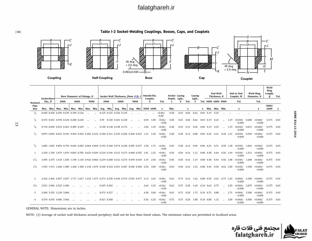
Table I-2ð16Þ Socket-Welding Couplings, Bosses, Caps, and Couplets
NominalPipeSize
SocketBoreDia., B
Bore Diameter of Fittings, D Socket Wall Thickness, [Note (1)], C OutsideDia.Couplet,
G Tol.
SocketDepth,
J
LayingLgth.,E Tol.
LayingLgth.,F Tol.
End WallThickness, K
End to EndCouplet, M
Weld RingDiameter, N
WeldRingLength,
Q Tol.
3000 6000 9000 3000 6000 9000 3000 6000 9000 Tol. Tol.
Max. Min. Max. Min. Max. Min. Max. Min. Avg. Min. Avg. Min. Avg. Min. 3000 6000 ± Min. ± ± Min. Min. Min. ± ±3000/6000 ±
1∕8 0.440 0.420 0.299 0.239 0.189 0.126 … … 0.125 0.125 0.156 0.135 … … … … +0.06/−0.00
0.38 0.25 0.06 0.62 0.03 0.19 0.25 … … … … … … …
1∕4 0.575 0.555 0.394 0.334 0.280 0.220 … … 3.78 0.130 0.181 0.158 … … 0.94 1.00 +0.06/−0.00
0.38 0.25 0.06 0.62 0.03 0.19 0.25 … 1.19 +0.030/−0.000
0.688 +0.060/−0.000
0.375 0.03
3∕8 0.710 0.690 0.523 0.463 0.389 0.329 … … 0.158 0.138 0.198 0.172 … … 1.06 1.25 +0.06/−0.00
0.38 0.25 0.12 0.69 0.06 0.19 0.25 … 1.19 +0.030/−0.000
0.813 +0.060/−0.000
0.375 0.03
1∕2 0.875 0.855 0.652 0.592 0.494 0.434 0.282 0.222 0.184 0.161 0.235 0.204 0.368 0.322 1.31 1.50 +0.06/−0.00
0.38 0.38 0.12 0.88 0.06 0.25 0.31 0.44 1.31 +0.030/−0.000
0.938 +0.060/−0.000
0.375 0.03
3∕4 1.085 1.065 0.854 0.794 0.642 0.582 0.464 0.404 0.193 0.168 0.274 0.238 0.385 0.337 1.50 1.75 +0.06/−0.00
0.50 0.38 0.12 0.94 0.06 0.25 0.31 0.50 1.38 +0.030/−0.000
1.063 +0.060/−0.000
0.375 0.03
1 1.350 1.330 1.079 1.019 0.845 0.785 0.629 0.569 0.224 0.196 0.312 0.273 0.448 0.392 1.81 2.25 +0.06/−0.00
0.50 0.50 0.16 1.12 0.08 0.38 0.44 0.56 1.69 +0.030/−0.000
1.313 +0.060/−0.000
0.375 0.03
11∕4 1.695 1.675 1.410 1.350 1.190 1.130 0.926 0.866 0.239 0.208 0.312 0.273 0.478 0.418 2.19 2.50 +0.06/−0.00
0.50 0.50 0.16 1.19 0.08 0.38 0.44 0.56 1.88 +0.030/−0.000
1.688 +0.060/−0.000
0.375 0.03
11∕2 1.935 1.915 1.640 1.580 1.368 1.308 1.130 1.070 0.250 0.218 0.351 0.307 0.500 0.438 2.50 3.00 +0.06/−0.00
0.50 0.50 0.16 1.25 0.08 0.44 0.50 0.62 2.00 +0.030/−0.000
1.938 +0.060/−0.000
0.375 0.03
2 2.426 2.406 2.097 2.037 1.717 1.657 1.533 1.473 0.273 0.238 0.430 0.374 0.545 0.477 3.13 3.63 +0.06/−0.00
0.62 0.75 0.16 1.62 0.08 0.50 0.62 0.75 2.25 +0.060/−0.000
2.438 +0.060/−0.000
0.375 0.03
21∕2 2.931 2.906 2.529 2.409 … … … … 0.345 0.302 … … … … 3.63 4.25 +0.06/−0.00
0.62 0.75 0.20 1.69 0.10 0.62 0.75 … 2.50 +0.060/−0.000
2.875 +0.060/−0.000
0.375 0.03
3 3.560 3.535 3.128 3.008 … … … … 0.375 0.327 … … … … 4.38 5.00 +0.06/−0.00
0.62 0.75 0.20 1.75 0.10 0.75 0.88 … 2.75 +0.060/−0.000
3.500 +0.060/−0.000
0.375 0.03
4 4.570 4.545 4.086 3.966 … … … … 0.421 0.368 … … … … 5.56 6.25 +0.06/−0.00
0.75 0.75 0.20 1.88 0.10 0.88 1.12 … 3.00 +0.060/−0.000
4.500 +0.060/−0.000
0.375 0.03
GENERAL NOTE: Dimensions are in inches.
NOTE: (1) Average of socket wall thickness around periphery shall not be less than listed values. The minimum values are permitted in localized areas.
ASMEB16.11-2016
13
falatghareh.irfalatghareh.ir

Table I-3ð16Þ Threaded Elbows, Tees, and Crosses
NominalPipeSize
Center-to-End Elbows,Tees, and Crosses, A
Center-to-End45-deg Elbow, C
Outside Diameter ofBand, H
Minimum WallThickness, G
MinimumLength ofThread[Note (1)]
2000 3000 6000 2000 3000 6000 2000 3000 6000 2000 3000 6000 B L21∕8 0.81 0.81 0.97 0.69 0.69 0.75 0.88 0.88 1.00 0.125 0.125 0.250 0.25 0.26391∕4 0.81 0.97 1.12 0.69 0.75 0.88 0.88 1.00 1.31 0.125 0.130 0.260 0.32 0.40183∕8 0.97 1.12 1.31 0.75 0.88 1.00 1.00 1.31 1.50 0.125 0.138 0.275 0.36 0.40781∕2 1.12 1.31 1.50 0.88 1.00 1.12 1.31 1.50 1.81 0.125 0.161 0.321 0.43 0.5337
3∕4 1.31 1.50 1.75 1.00 1.12 1.31 1.50 1.81 2.19 0.125 0.170 0.336 0.50 0.54571 1.50 1.75 2.00 1.12 1.31 1.38 1.81 2.19 2.44 0.145 0.196 0.391 0.58 0.682811∕4 1.75 2.00 2.38 1.31 1.38 1.69 2.19 2.44 2.97 0.153 0.208 0.417 0.67 0.706811∕2 2.00 2.38 2.50 1.38 1.69 1.72 2.44 2.97 3.31 0.158 0.219 0.436 0.70 0.7235
2 2.38 2.50 3.25 1.69 1.72 2.06 2.97 3.31 4.00 0.168 0.281 0.476 0.75 0.756521∕2 3.00 3.25 3.75 2.06 2.06 2.50 3.62 4.00 4.75 0.221 0.301 0.602 0.93 1.13803 3.38 3.75 4.19 2.50 2.50 3.12 4.31 4.75 5.75 0.236 0.348 0.655 1.02 1.20004 4.19 4.50 4.50 3.12 3.12 3.12 5.75 6.00 6.00 0.258 0.440 0.735 1.09 1.3000
GENERAL NOTE: Dimensions are in inches.
NOTE: (1) Dimension B is minimum length of perfect thread. The length of useful thread (B plus threads with fully formed roots and flat crests)shall not be less than L2 (effective length of external thread) required by American National Standard for Pipe Threads (ASME B1.20.1; see para.6.3).
ASME B16.11-2016
14
falatghareh.irfalatghareh.ir

Table I-4ð16Þ Threaded Street Elbows
NominalPipe Size,
NPS
Center-to-FemaleEnd Street Ells,A [Note (1)]
Center-to-MaleEnd Street Ells, J
Outside Diameter ofBand, H[Note (2)]
Minimum WallThickness, G1
Minimum WallThickness, G2 [Note (3)]
Minimum LengthInternal Thread
[Note (4)]
MinimumLength
Male Thread,L
Class Designation Class Designation Class Designation Class Designation Class Designation3000 6000 3000 6000 3000 6000 3000 6000 3000 6000 B L2
1∕8 0.75 0.88 1.00 1.25 0.75 1.00 0.125 0.200 0.108 0.166 0.25 0.2639 0.381∕4 0.88 1.00 1.25 1.50 1.00 1.25 0.130 0.223 0.127 0.208 0.32 0.4018 0.443∕8 1.00 1.12 1.50 1.62 1.25 1.50 0.138 0.275 0.138 0.220 0.36 0.4078 0.501∕2 1.12 1.38 1.62 1.88 1.50 1.75 0.161 0.321 0.164 0.257 0.43 0.5337 0.563∕4 1.38 1.75 1.88 2.25 1.75 2.00 0.170 0.336 0.192 0.270 0.50 0.5457 0.62
1 1.75 2.00 2.25 2.62 2.00 2.44 0.196 0.391 0.219 0.313 0.58 0.6828 0.7511∕4 2.00 2.12 2.62 2.81 2.44 2.75 0.208 0.417 0.219 0.334 0.67 0.7068 0.8111∕2 2.12 2.50 2.81 3.31 2.75 3.31 0.219 0.436 0.246 0.350 0.70 0.7235 0.812 2.50 3.25 3.31 4.13 3.31 4.00 0.281 0.476 0.301 0.382 0.75 0.7565 0.88
GENERAL NOTE: Dimensions are in inches.
NOTES:(1) Dimension A of Table I-3 for the appropriate fitting size may also be used at the option of the manufacturer.(2) Dimension H of Table I-3 for the appropriate fitting size may also be used at the option of the manufacturer.(3) Wall thickness before threading.(4) DimensionB isminimum length of perfect thread. The length of useful thread (Bplus threadswith fully formed roots and flat crests) shall not be less than L2 (effective length of external thread)
required by American National Standard for Pipe Threads (ASME B1.20.1; see para. 6.3).
ASMEB16.11-2016
15
falatghareh.irfalatghareh.ir

Table I-5ð16Þ Threaded Couplings, Bosses, Caps, and Couplets
NominalPipeSize
OutsideDiameter, D
OutsideDiameterCouplet, E Tol.
End-to-End
Coupling,W
End-to- EndCaps,P
End-to-EndCoupling, M Tol.
Minimum EndWall Thickness,
G
WeldRing
Length, Q Tol.
Weld RingDiameter,
N Tol.
MinimumLength ofThread[Note (1)]
3000 6000 3000 6000± 3000/
6000 3000 60003000/6000
±3000 6000
3000/6000
± 3000/6000
±3000/6000B L2
1∕8 0.62 0.88 … … … 1.25 0.75 0.88 … … 0.19 0.25 … … … … 0.25 0.26391∕4 0.75 1.00 0.928 1.000 +0.06/−0.00 1.38 1.00 1.06 1.188 +0.03/−0.00 0.19 0.25 0.375 0.03 0.688 +0.06/−0.00 0.32 0.40183∕8 0.88 1.25 1.063 1.250 +0.06/−0.00 1.50 1.00 1.06 1.188 +0.03/−0.00 0.19 0.25 0.375 0.03 0.813 +0.06/−0.00 0.36 0.40781∕2 1.12 1.50 1.313 1.500 +0.06/−0.00 1.88 1.25 1.31 1.313 +0.03/−0.00 0.25 0.31 0.375 0.03 0.938 +0.06/−0.00 0.43 0.5337
3∕4 1.38 1.75 1.500 1.750 +0.06/−0.00 2.00 1.44 1.50 1.375 +0.03/−0.00 0.25 0.31 0.375 0.03 1.063 +0.06/−0.00 0.50 0.54571 1.75 2.25 1.813 2.250 +0.06/−0.00 2.38 1.62 1.69 1.688 +0.03/−0.00 0.38 0.44 0.375 0.03 1.313 +0.06/−0.00 0.58 0.682811∕4 2.25 2.50 2.188 2.500 +0.06/−0.00 2.62 1.75 1.81 1.875 +0.03/−0.00 0.38 0.44 0.375 0.03 1.688 +0.06/−0.00 0.67 0.706811∕2 2.50 3.00 2.500 3.000 +0.06/−0.00 3.12 1.75 1.88 2.000 +0.03/−0.00 0.44 0.50 0.375 0.03 1.938 +0.06/−0.00 0.70 0.7235
2 3.00 3.62 3.125 3.625 +0.06/−0.00 3.38 1.88 2.00 2.250 +0.06/−0.00 0.50 0.62 0.375 0.03 2.438 +0.06/−0.00 0.75 0.756521∕2 3.62 4.25 3.625 4.250 +0.06/−0.00 3.62 2.38 2.50 2.500 +0.06/−0.00 0.62 0.75 0.375 0.03 2.875 +0.06/−0.00 0.93 1.13803 1.25 5.00 4.375 5.000 +0.06/−0.00 4.25 2.56 2.69 2.750 +0.06/−0.00 0.75 0.88 0.375 0.03 3.500 +0.06/−0.00 1.02 1.20004 5.50 6.25 5.563 6.250 +0.06/−0.00 4.75 2.69 2.94 3.000 +0.06/−0.00 0.88 1.12 0.375 0.03 4.500 +0.06/−0.00 1.09 1.3000
GENERAL NOTES:(a) Dimensions are in millimeters.(b) The wall thickness away from the threaded ends shall meet the minimum wall thickness requirements of Table I-2 for the appropriate NPS and class Designation fitting.
NOTE: (1) Dimension B is minimum length of perfect thread. The length of useful thread (B plus threads with fully formed roots and flat crests) shall be less than L2 (effective length of externalthread) required by American National Standard for Pipe Threads (ASME B1.20.1; see para. 6.3).
ASMEB16.11-2016
16
falatghareh.irfalatghareh.ir

Table I-6 Plugs and Bushings
NominalPipeSize
MinimumLength, A
Square Head Plugs Round Head Plugs Hex Plugs and Bushings
MinimumSquareHeight, B
MinimumWidthFlats, C[Note (2)]
NominalHead
Diameter, EMinimumLength, D
Nominal WidthFlats, F
[Note (2)]
Minimum Hex Height
Bushing, G Plug, H1∕8 0.38 0.25 0.28 0.41 1.38 0.44 … 0.251∕4 0.44 0.25 0.38 0.53 1.62 0.62 0.12 0.253∕8 0.50 0.31 0.44 0.69 1.62 0.69 0.16 0.311∕2 0.56 0.38 0.56 0.84 1.75 0.88 0.19 0.31
3∕4 0.62 0.44 0.62 1.06 1.75 1.06 0.22 0.381 0.75 0.50 0.81 1.31 2.00 1.38 0.25 0.3811∕4 0.81 0.56 0.94 1.69 2.00 1.75 0.28 0.5611∕2 0.81 0.62 1.12 1.91 2.00 2.00 0.31 0.62
2 0.88 0.69 1.31 2.38 2.50 2.50 0.34 0.6921∕2 1.06 0.75 1.50 2.88 2.75 3.00 0.38 0.753 1.12 0.81 1.69 3.50 2.75 3.50 0.41 0.814 1.25 1.00 2.50 4.50 3.00 4.62 0.50 1.00
GENERAL NOTE: Dimensions are in inches.
NOTES:(1) CautionaryNote RegardingHexBushings:Hexhead bushings of one-size reduction should not beused in serviceswhere theymight be subject
to harmful loads and forces other than internal pressures.(2) Manufacturer's applied tolerance shall ensure dimension will fit U.S. Customary tooling.
ASME B16.11-2016
17
falatghareh.irfalatghareh.ir

MANDATORY APPENDIX IIREFERENCESð16Þ
The following is a list of publications referenced in thisStandard.
ASME B1.20.1, Pipe Threads, General Purpose (Inch)ASME B16.34, Valves — Flanged, Threaded, and WeldingEnd
ASMEB36.10M,Welded and SeamlessWrought Steel PipePublisher: The American Society of Mechanical Engineers(ASME), Two Park Avenue, New York, NY 10016-5990(www.asme.org)
ASTM A105/A105M-14, Specification for Carbon SteelForgings for Piping Components
ASTMA182/A182M-16, Specification for ForgedorRolledAlloy and Stainless Steel Pipe Flanges, Forged Fittings,and Valves and Parts for High-Temperature Service
ASTM A234/A234M-15, Specification for Piping Fittingsof Wrought Carbon Steel and Alloy Steel for Moderateand High Temperature Service
ASTM A350/A350M-15, Specification for Carbon andLow-Al loy Stee l Forg ings , Requ ir ing NotchToughness Testing for Piping Components
ASTM A403/A403M-16, Specification for WroughtAustenitic Stainless Steel Piping Fittings
ASTM A420/A420M-16, Specification for Piping Fittingsof Wrought Carbon Steel and Alloy Steel for Low-Temperature Service
ASTM A815/A815M-14ε1,Specification for WroughtFerritic, Ferritic/Austenitic, and Martensitic StainlessSteel Piping Fittings
ASTM A960/A960M-16, Specification for CommonRequirements for Wrought Steel Piping Fittings
ASTM A961/A961M-16, Standard Specification forCommon Requirements for Steel Flanges, ForgedFittings, Valves, and Parts for Piping Applications
ASTMB366-16ε1, Specification forFactory-MadeWroughtNickel and Nickel Alloy Fittings
ASTM B462-15, Specification for Forged or Rolled UNSN06030, N06022, N06035, N06200, N06059,N06686, N08020, N08024, N08026, N08367,N10276, N10665, N10675, N10629, N08031,N06045, N06025, and R20033 Alloy Pipe Flanges,Forged Fittings, and Valves and Parts for CorrosiveHigh-Temperature Service
ASTM B564-15, Specification for Nickel Alloy ForgingsPublisher: American Society for Testing and Materials(ASTM International), 100 Barr Harbor Drive, P.O.Box C700, West Conshohocken, PA 19428-2959(www.astm.org)
ISO 9000:2005, Quality management systems —Fundamentals and vocabulary1
ISO 9001:2008, Quality management systems —Requirements1
ISO 9004:2009, Managing for the sustained success of anorganization — A quality management approach1
Publisher: International Organization for Standardization(ISO),Central Secretariat, ChemindeBlandonnet8, Casepostale 401, 1214 Vernier, Geneva, Switzerland(www.iso.org)
1May also be obtained from the AmericanNational Standards Institute(ANSI), 25 West 43rd Street, New York, NY 10036.
ASME B16.11-2016
18
falatghareh.irfalatghareh.ir

NONMANDATORY APPENDIX AQUALITY SYSTEM PROGRAM
The products manufactured in accordance with thisStandard shall be produced under a quality systemprogram following the principles of an appropriate stan-dard from the ISO 9000 series.1 A determination of theneed for registration and/or certification of theproduct manufacturer's quality system program by anindependent oganization shall be the responsibility ofthe manufacturer. The detailed documentation demon-
strating program compliance shall be available to thepurchaser at the manufacturer's facility. A writtensummary description of the program utilized by theproduct manufacturer shall be available to the purchaserupon request. The product manufacturer is defined as theentity whose name or trademark appears on the productin accordance with the marking or identification require-ments of this Standard.
1 The series is also available from the American National StandardsInstitute (ANSI) and the American Society for Quality (ASQ) asAmerican National Standards that are identified by the prefix “Q” repla-cing the prefix “ISO.” Each standard of the series is listed underReferences in Mandatory Appendix II.
ASME B16.11-2016
19
falatghareh.irfalatghareh.ir

ASME B16.11-2016
falatghareh.irfalatghareh.ir


![Section 6 High Pressure Fittings - aapindustries.com.au · HIGH PRESSURE FITTINGS [6] High Pressure 3000lb Threaded 90 degree Elbow High Pressure Asme B16.11-2009 90 Degree Threaded](https://img.dokumen.tips/doc/110x75/5e66e44c39bca404a7661857/section-6-high-pressure-fittings-high-pressure-fittings-6-high-pressure-3000lb.jpg)