Embed Size (px)
Citation preview
Pub. Name Pub. No.
’93 LEXUS ES300 Repair Manual RM318U1
Automatic Transaxle Applicable Model
A540E ’93 Lexus ES300
FOREWORD
This repair manual covers Disassembly, Inspection and As-sembly procedures for the following Automatic Transaxle:
For On-vehicle Servicing (Inspection, Adjustment, Trouble-shooting, Removal and Installation) of Automatic Transaxle,refer to the repair manual for the applicable vehicle model.
All information contained in this manual is the most up-to-date at the time of publication. However, specifications andprocedures are subject to change without notice.
TOYOTA MOTOR CORPORATION
�1992 TOYOTA MOTOR CORPORATIONAll rights reserved. This book may not be repro-duced or copied, in whole or in part, without thewritten permission of Toyota Motor Corporation.

REPAIR PROCEDURES
HOW TO USE THIS MANUALTo assist you in finding your way through the manual, the Section Title and major heading are given atthe top of every page.
PREPARATION
Preparation lists the SST (Special Service Tools), recommended tools, equipment, lubricant and SSM(Special Service Materials) which should be prepared before beginning the operation and explains thepurpose of each one.
Most repair operations begin with an overview illustration. It identifies the components and shows howthe parts fit together.Example:
AT8669
♦ Non-reusable part
N-m (kgf-cm, ft-lbf) : Specified torque
♦ O-Ring♦ Oil Seal
Drive Gear
Thrust Washer
Oil Seal Ring
Driven Gear10 (100, 7)
Pump Body Stator Shaft
IN-2-INTRODUCTION HOW TO USE THIS MANUAL

(a) Place SST and a dial indicator onto the overdrive brakepiston as shown in the illustration.SST 09350-30020 (09350-06120)
The procedures are presented in a step-by-step format:� The illustration shows what to do and where to do it.� The task heading tells what to do.� The detailed text tells how to perform the task and gives other information such as specifi-
cations and warnings.Example:
This format provides the experienced technician with a FAST TRACK to the information needed. Theupper case task heading can be read at a glance when necessary, and the text below it provides de-tailed information. Important specifications and warnings always stand out in bold type.
REFERENCES
References have been kept to a minimum. However, when they are required you are given the page torefer to.
SPECIFICATIONS
Specifications are presented in bold type throughout the text where needed. You never have to leavethe procedure to look up your specifications. They are also found at the back of AX section, for quickreference.
Illustration:what to do and where
Set part No.
Piston stroke: 1.40 - 1.70 mm (0.0551 - 0.0669 in.)
Task heading: what to do
21. CHECK PISTON STROKE OF OVERDRIVE BRAKE
Component part No.
Specification
(b) Measure the stroke applying and releasing the com-pressed air ( 392 - 785 kPa, 4 - 8 kgf/cm2 or 57 - 114psi) as shown in the illustration.
Detail text: how to do task
-INTRODUCTION HOW TO USE THIS MANUALIN-3
CAUTIONS, NOTICES, HINTS:
� CAUTIONS are presented in bold type, and indicate there is a possibility of injury to you or otherpeople.
� NOTICES are also presented in bold type, and indicate the possibility of damage to the compo-nents being repaired.
� HINTS are separated from the text but do not appear in bold. They provide additional informationto help you perform the repair efficiently.
Sl UNIT
The UNITS given in this manual are primarily expressed according to with the Sl UNIT (InternationalSystem of Unit), and alternately expressed in the metric system and in the English System.Example:Torque: 30 N-m (310 kgf-cm, 22 ft-lbf)
IN-4-INTRODUCTION HOW TO USE THIS MANUAL

IN0036
Seal Lock Adhesive
FI1066
1. Use fender, seat and floor covers to keep the vehicleclean and prevent damage.
2. During disassembly, keep parts in the appropriateorder to facilitate reassembly.
3. Observe the following:
(a) Before performing electrical work, disconnect thenegative cable from the battery terminal.
(b) If it is necessary to disconnect the battery for in-spection or repair, always disconnect the cablefrom the negative (-) terminal which is grounded tothe vehicle body.
(c) To prevent damage to the battery terminal post,loosen the terminal nut and raise the cable straightup without twisting or prying it.
(d) Clean the battery terminal posts and cable termi-nals with a clean shop rag. Do not scrape themwith a file or other abrasive objects.
(e) Install the cable terminal to the battery post withthe nut loose, and tighten the nut after installation.Do not use a hammer to tap the terminal onto thepost.
(f) Be sure the cover for the positive (+) terminal isproperly in place.
4. Check hose and wiring connectors to make sure thatthey are secure and correct.
5. Non-reusable parts
(a) Always replace cotter pins, gaskets, O-rings andoil seals etc. with new ones.
(b) Non-reusable parts are indicated in the compo-nent illustrations by the ”♦ ” symbol.
GENERAL REPAIR INSTRUCTIONS
6. Precoated parts Precoated parts are bolts and nuts, etc. that are coatedwith a seal lock adhesive at the factory.
(a) If a precoated part is retightened, loosened orcaused to move in any way, it must be recoated withthe specified adhesive.
-INTRODUCTION GENERAL REPAIR INSTRUCTIONSIN-5

(b) When reusing precoated parts, clean off the oldadhesive and dry with compressed air. Then applythe specified seal lock adhesive to the bolt, nut orthreads.
(c) Precoated parts are indicated in the component illustrations by the ”�” symbol.
7. When necessary, use a sealer on gaskets to preventleaks.
8. Carefully observe all specifications for bolt tighteningtorques. Always use a torque wrench.
9. Use of special service tools (SST) and special servicematerials (SSM) may be required, depending on thenature of the repair. Be sure to use SST and SSMwhere specified and follow the proper work proce-dure. A list of SST and SSM can be found at the prep-aration of AX section.
Fuse
Equal Amperage Rating
10. When replacing fuses, be sure the new fuse has thecorrect amperage rating. DO NOT exceed the ratingor use one with a lower rating.
BE1366
11. To pull apart electrical connectors, pull on the con-nector itself, not the wires.
12. Care must be taken when jacking up and supportingthe vehicle. Be sure to lift and support the vehicle atthe proper locations.(a) If the vehicle is to be jacked up only at the front or
rear end, be sure to block the wheels at the oppo-site end in order to ensure safety.
(b) After the vehicle is jacked up, be sure to support iton stands. It is extremely dangerous to do anywork on a vehicle raised on a jack alone, even fora small job that can be finished quickly.
WRONG CORRECT
IN0252
IN-6-INTRODUCTION GENERAL REPAIR INSTRUCTIONS
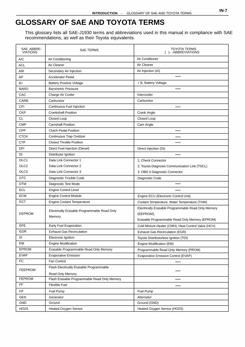
SAE ABBRE-VIATIONS
SAE TERMS TOYOTA TERMS( )- -ABBREVIATIONS
A/C Air Conditioning Air Conditioner
ACL Air Cleaner Air Cleaner
AIR Secondary Air Injection Air Injection (AI)
AP Accelerator Pedal
B+ Battery Positive Voltage + B, Battery Voltage
BARO Barometric Pressure
CAC Charge Air Cooler Intercooler
CARB Carburetor Carburetor
CFI Continuous Fuel Injection
CKP Crankshaft Position Crank Angle
CL Closed Loop Closed Loop
CMP Camshaft Position Cam Angle
CPP Clutch Pedal Position
CTOX Continuous Trap Oxidizer
CTP Closed Throttle Position
DFl Direct Fuel Injection (Diesel) Direct Injection (DI)
DI Distributor Ignition
DLC1
DLC2
DLC3
Data Link Connector 1
Data Link Connector 2
Data Link Connector 3
1: Check Connector
2: Toyota Diagnosis Communication Link (TDCL)
3: OBD II Diagnostic Connector
DTC Diagnostic Trouble Code Diagnostic Code
DTM Diagnostic Test Mode
ECL Engine Control Level
ECM Engine Control Module Engine ECU (Electronic Control Unit)
ECT Engine Coolant Temperature Coolant Temperature, Water Temperature (THW)
EEPROMElectrically Erasable Programmable Read Only
Memory
Electrically Erasable Programmable Read Only Memory
(EEPROM),
Erasable Programmable Read Only Memory (EPROM)
EFE Early Fuel Evaporation Cold Mixture Heater (CMH), Heat Control Valve (HCV)
EGR Exhaust Gas Recirculation Exhaust Gas Recirculation (EGR)
El Electronic Ignition Toyota Distributorless Ignition (TDI)
EM Engine Modification Engine Modification (EM)
EPROM Erasable Programmable Read Only Memory Programmable Read Only Memory (PROM)
EVAP Evaporative Emission Evaporative Emission Control (EVAP)
FC Fan Control
FEEPROMFlash Electrically Erasable Programmable
Read Only Memory
FEPROM Flash Erasable Programmable Read Only Memory
FF Flexible Fuel
FP Fuel Pump Fuel Pump
GEN Generator Alternator
GND Ground Ground (GND)
HO2S Heated Oxygen Sensor Heated Oxygen Sensor (HO2S)
This glossary lists all SAE-J1930 terms and abbreviations used in this manual in compliance with SAErecommendations, as well as their Toyota equivalents.
GLOSSARY OF SAE AND TOYOTA TERMS-INTRODUCTION GLOSSARY OF SAE AND TOYOTA TERMS
IN-7

IAC Idle Air Control Idle Speed Control (ISC)
IAT Intake Air Temperature Intake or Inlet Air Temperature
ICM Ignition Control Module
IFI Indirect Fuel Injection Indirect Injection
IFS Inertia Fuel-Shutoff
ISC Idle Speed Control
KS Knock Sensor Knock Sensor
MAF Mass Air Flow Air Flow Meter
MAP Manifold Absolute PressureManifold Pressure
Intake Vacuum
MC Mixture Control
Electric Bleed Air Control Valve (EBCV)
Mixture Control Valve (MCV)
Electric Air Control Valve (EACV)
MDP Manifold Differential Pressure
MFl Multiport Fuel Injection Electronic Fuel Injection (EFI)
MIL Malfunction Indicator Lamp Check Engine Light
MST Manifold Surface Temperature
MVZ Manifold Vacuum Zone
NVRAM Non-Volatile Random Access Memory
O2S Oxygen Sensor Oxygen Sensor, O2 Sensor (O2S)
OBD On-Board Diagnostic On-Board Diagnostic (OBD)
OC Oxidation Catalytic Converter Oxidation Catalyst Converter (OC), CCo
OP Open Loop Open Loop
PAIR Pulsed Secondary Air Injection Air Suction (AS)
PCM Powertrain Control Module
PNP Park/Neutral Position
PROM Programmable Read Only Memory
PSP Power Steering Pressure
PTOX Periodic Trap OxidizerDiesel Particulate Filter (DPF)
Diesel Particulate Trap (DPT)
RAM Random Access Memory Random Access Memory (RAM)
RM Relay Module
ROM Read Only Memory Read Only Memory (ROM)
RPM Engine Speed Engine Speed
SC Supercharger Supercharger
SCB Supercharger Bypass
SFI Sequential Multiport Fuel Injection Electronic Fuel Injection (EFI), Sequential Injection
SPL Smoke Puff Limiter
SRI Service Reminder Indicator
SRT System Readiness Test
ST Scan Tool
TB Throttle Body Throttle Body
TBI Throttle Body Fuel InjectionSingle Point Injection
Central Fuel Injection (Ci)
TC Turbocharger Turbocharger
TCC Torque Converter Clutch Torque Converter
TCM Transmission Control Module Transmission ECU (Electronic Control Unit)
TP Throttle Position Throttle Position
TR Transmission Range
IN-8-INTRODUCTION GLOSSARY OF SAE AND TOYOTA TERMS

TVV Thermal Vacuum ValveBimetal Vacuum Switching Valve (BVSV)
Thermostatic Vacuum Switching Valve (TVSV)
TWC Three-Way Catalytic ConverterThree-Way Catalyst (TWC)
CCRO
TWC + OC Three-Way + Oxidation Catalytic Converter CCR + CCo
VAF Volume Air Flow Air Flow Meter
VR Voltage Regulator Voltage Regulator
VSS Vehicle Speed Sensor Vehicle Speed Sensor (Read Switch Type)
WOT Wide Open Throttle Full Throttle
WU-OC Warm Up Oxidation Catalytic Converter
WU-TWC Warm Up Three-Way Catalytic Converter Manifold Converter
3GR Third Gear
4GR Fourth Gear
-INTRODUCTION GLOSSARY OF SAE AND TOYOTA TERMSIN-9

ATF Automatic Transaxle Fluid
B0 Overdrive Brake
B1 Second Coast Brake
B2 Second Brake
B3 First and Reverse Brake
C0 Overdrive Clutch
C1 Forward Clutch
C2 Direct Clutch
D Disc
D/F Differential
F Flange
F1 No. 1 One-way Clutch
F2 No. 2 One-way Clutch
LH Left-Hand
MP Multipurpose
O/D Overdrive
P Plate
RH Right-Hand
SSM Special Service Materials
SST Special Service Tools
ABBREVIATIONS USED IN THISMANUAL
IN-10-INTRODUCTION ABBREVIATIONS USED IN THIS MANUAL
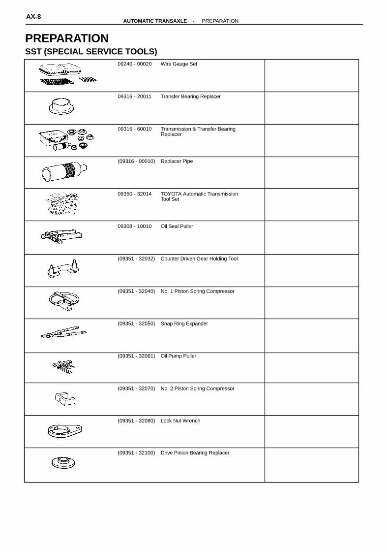
Wire Gauge Set09240 - 00020
Transfer Bearing Replacer09316 - 20011
Transmission & Transfer BearingReplacer
09316 - 60010
Replacer Pipe(09316 - 00010)
TOYOTA Automatic TransmissionTool Set
09350 - 32014
Oil Seal Puller09308 - 10010
Counter Driven Gear Holding Tool(09351 - 32032)
No. 1 Piston Spring Compressor(09351 - 32040)
Snap Ring Expander(09351 - 32050)
Oil Pump Puller(09351 - 32061)
No. 2 Piston Spring Compressor(09351 - 32070)
Lock Nut Wrench(09351 - 32080)
Drive Pinion Bearing Replacer(09351 - 32100)
PREPARATIONSST (SPECIAL SERVICE TOOLS)
AX-8-AUTOMATIC TRANSAXLE PREPARATION

Pin Punch09031 - 00030
Feeler gauge Check major clearance.
Vernier calipers Check length of second coastbrake piston rod.
Dial indicator with magneticbase Check piston stroke and end playof the output shaft.
Dial indicator Check inside diameter ofmajor bushing.
Straight edge Check side clearance of oil pump.
Torque wrench
Overdrive Bearing Replacer(09351 - 32120)
Oil Seal Replacer(09351 - 32140)
Oil Seal Replacer(09351 - 32150)
Measure Terminal(09351 - 32190)
No. 3 Piston Spring Compressor(09351 - 32200)
Steering Worm Bearing Puller09612 - 65014 Remove pinion shaft Bearing outerrace
Universal Puller09950 - 20017
RECOMMENDED TOOL
EQUIPMENT
-AUTOMATIC TRANSAXLE PREPARATIONAX-9

Seal Packing 1281, Three bond 1281 or equivalent
08826 - 00090 Differential LH bearing retainerDifferential RH retainer
Adhesive 1324, THREE BOND 1324 or equivalent
08833 - 00070 Differential RH retainer set bolt
Item Capacity Classification
Dry fill
Drain and refill
Automatic transaxle fluid
6.5 liters (6.9 US qts, 5.7 Imp. qts)
2.5 liters (2.6 US qts, 2.2 Imp. qts)
ATF DEXRON� II
Differential oil 0.8 liter (0.8 US qts, 0.7 Imp. qts) ATF DEXRON� II
LUBRICANT
SSM (SPECIAL SERVICE MATERIALS)
AX-10-AUTOMATIC TRANSAXLE PREPARATION

Mark Class Mark Class
Hexagon head bolt
4
Bolt head No.
4-
5-
6-
7-
8-
9-
10-
11-
4T
5T
6T
7T
8T
9T
10T
11T
Stud bolt
No mark
4T
No mark 4T
Grooved
6T
Hexagon flange bolt
w/ washer hexagon bolt
No mark 4T
Hexagon head bolt Two
protrudinglines 5T
Hexagon flange bolt
w/ washer hexagon bolt
Two protrudinglines 6T Welded bolt
4T
Hexagon head bolt Three
protrudinglines 7T
Hexagon head bolt Four
protrudinglines 8T
STANDARD BOLT TORQUE SPECIFICATIONS
HOW TO DETERMINE BOLT STRENGTH
-INTRODUCTION STANDARD BOLT TORQUE SPECIFICATIONSIN-1 1
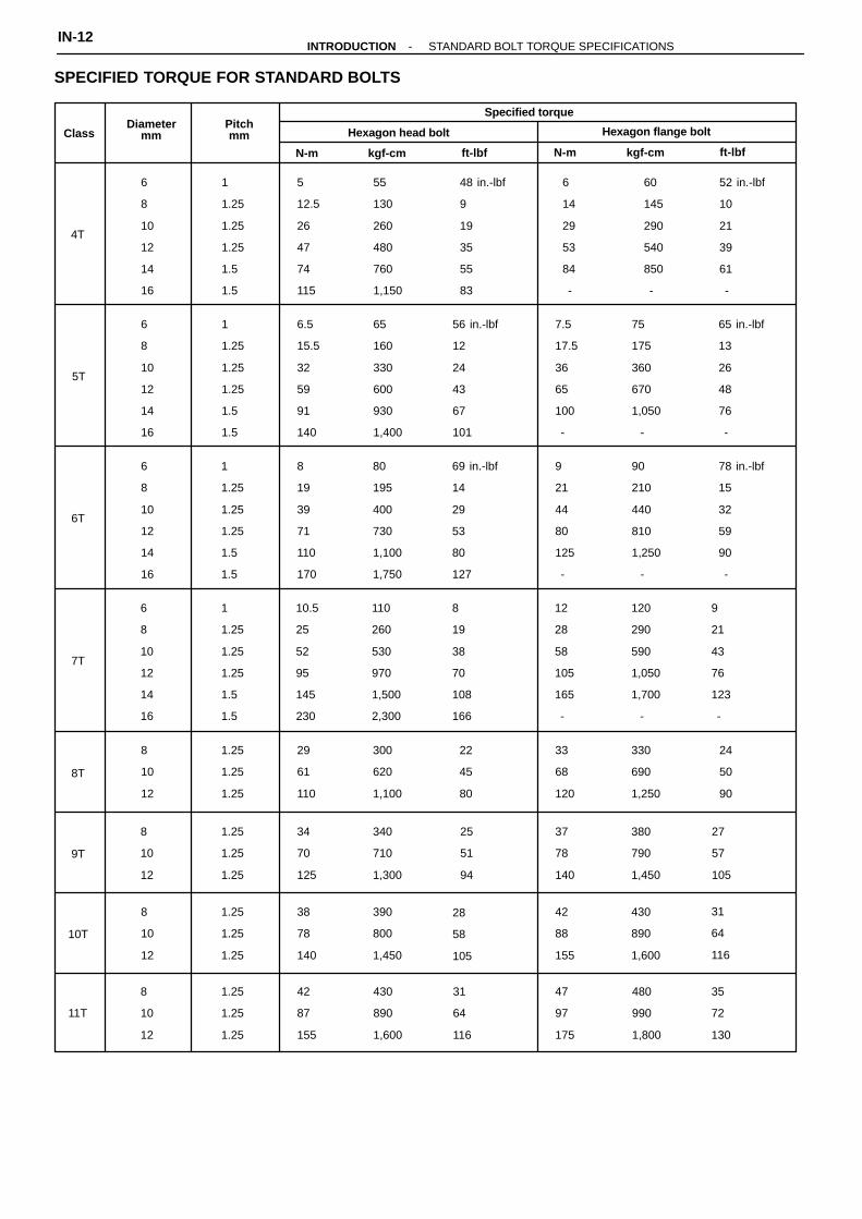
ClassDiameter
mmPitchmm
Specified torque
Hexagon head bolt Hexagon flange bolt
kgf-cm ft-lbfN-m N-m kgf-cm ft-lbf
4T
6
8
10
12
14
16
1
1.25
1.25
1.25
1.5
1.5
55
130
260
480
760
1,150
5
12.5
26
47
74
115
48 in.-lbf
9
19
35
55
83
60
145
290
540
850
-
6
14
29
53
84
-
52 in.-lbf
10
21
39
61
-
5T
6
8
10
12
14
16
1
1.25
1.25
1.25
1.5
1.5
65
160
330
600
930
1,400
6.5
15.5
32
59
91
140
56 in.-lbf
12
24
43
67
101
65 in.-lbf
13
26
48
76
-
7.5
17.5
36
65
100
-
75
175
360
670
1,050
-
6T
6
8
10
12
14
16
1
1.25
1.25
1.25
1.5
1.5
80
195
400
730
1,100
1,750
69 in.-lbf
14
29
53
80
127
8
19
39
71
110
170
78 in.-lbf
15
32
59
90
-
9
21
44
80
125
-
90
210
440
810
1,250
-
7T
6
8
10
12
14
16
1
1.25
1.25
1.25
1.5
1.5
110
260
530
970
1,500
2,300
8
19
38
70
108
166
10.5
25
52
95
145
230
9
21
43
76
123
-
12
28
58
105
165
-
120
290
590
1,050
1,700
-
8T
8
10
12
1.25
1.25
1.25
300
620
1,100
29
61
110
22
45
80
33
68
120
24
50
90
330
690
1,250
9T
8
10
12
1.25
1.25
1.25
340
710
1,300
34
70
125
25
51
94
380
790
1,450
27
57
105
37
78
140
10T
8
10
12
1.25
1.25
1.25
390
800
1,450
38
78
140
28
58
105
42
88
155
31
64
116
430
890
1,600
11T
8
10
12
1.25
1.25
1.25
430
890
1,600
42
87
155
31
64
116
47
97
175
35
72
130
480
990
1,800
SPECIFIED TORQUE FOR STANDARD BOLTS
IN-12-INTRODUCTION STANDARD BOLT TORQUE SPECIFICATIONS
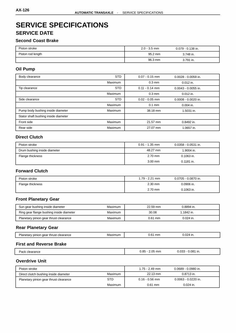
Planetary pinion gear thrust clearance Maximum 0.024 in.0.61 mm
Piston stroke 0.079 - 0.138 in.2.0 - 3.5 mm
Piston rod length 3.748 in.95.2 mm
3.791 in.96.3 mm
Body clearance STD 0.0028 - 0.0059 in.0.07 - 0.15 mm
Maximum 0.012 in.0.3 mm
STDTip clearance 0.0043 - 0.0055 in.0.11 - 0.14 mm
Maximum 0.012 in.0.3 mm
Side clearance STD 0.0008 - 0.0020 in.0.02 - 0.05 mm
Maximum 0.1 mm 0.004 in.
MaximumPump body bushing inside diameter 1.5031 in.38.18 mm
Stator shaft bushing inside diameter
Front side Maximum 0.8492 in.21.57 mm
Rear side Maximum 1.0657 in.27.07 mm
Piston stroke 0.0358 - 0.0531 in.0.91 - 1.35 mm
Drum bushing inside diameter 48.27 mm 1.9004 in.
Flange thickness 2.70 mm
3.00 mm
0.1063 in.
0.1181 in.
Piston stroke 1.79 - 2.21 mm 0.0705 - 0.0870 in.
Flange thickness 0.0906 in.
0.1063 in.
2.30 mm
2.70 mm
Sun gear bushing inside diameter Maximum 0.8894 in.22.59 mm
Ring gear flange bushing inside diameter Maximum 1.1842 in.30.08
Planetary pinion gear thrust clearance Maximum 0.61 mm 0.024 in.
Piston stroke 1.75 - 2.49 mm 0.0689 - 0.0980 in.
Direct clutch bushing inside diameter Maximum 0.8713 in.22.13 mm
STD
Maximum
Planetary pinion gear thrust clearance 0.16 - 0.56 mm
0.61 mm
0.0063 - 0.0220 in.
0.024 in.
Pack clearance 0.033 - 0.081 in.0.85 - 2.05 mm
SERVICE SPECIFICATIONSSERVICE DATESecond Coast Brake
Oil Pump
Direct Clutch
Forward Clutch
Front Planetary Gear
Rear Planetary Gear
First and Reverse Brake
Overdrive Unit
AX-126-AUTOMATIC TRANSAXLE SERVICE SPECIFICATIONS

KeyHeight
mm (in.)
Width
mm (in.)
Thickness
mm (in.)(Upper valve body)
Lock-up relay valve 6.5 (0.256) 5.0 (0.197) 3.2 (0.126)
Throttle modulator valve 6.5 (0.453) 5.0 (0.197) 3.2 (0.126)
Second coast modulator valve 6.5 (1.142) 5.0 (0.197) 3.2 (0.126)
Cut-back valve 9.2 (0.362) 5.0 (0.197) 3.2 (0.126)
No. 1 accumulator control valve 6.5 (0.256) 5.0 (0.197) 3.2 (0.126)
B1 orifice control valve 11.5 (0.453) 5.0 (0.197) 3.2 (0.126)
(Lower valve body)
Primary regulator valve 9.2 (0.362) 5.0 (0.197) 3.2 (0.126)
Secondary regulator valve 15.0 (0.591) 5.0 (0.197) 3.2 (0.126)
No. 2 accumulator control valve 9.2 (0.362) 5.0 (0.197) 3.2 (0.126)
1 - 2 shift valve 6.5 (0.256) 5.0 (0.197) 3.2 (0.126)2 - 3 shift valve 9.2 (0.362) 5.0 (0.197) 3.2 (0.126)3 - 4 shift valve 6.5 (0.256) 5.0 (0.197) 3.2 (0.126)Second lock valve 11.5 (0.453) 5.0 (0.197) 3.2 (0.126)
Low coast modulator valve 11.5 (0.453) 5.0 (0.197) 3.2 (0.126)
SpringFree length / Coil outer diameter
mm (in.)Total No. of coils / Color
(Upper valve body)
Second coast modulator valve 27.5 (1.083) / 8.9 (0.350) 14.6 / Brown
B1 orifice control valve 24.8 (0.976) / 8.0 (0.315) 12.0 / White
Down shift plug 29.8 (1.173) / 8.7 (0.343) 13.5 / Yellow
Throttle valve 30.7 (1.209) / 9.2 (0.6.2) 9.5 / Purple
Throttle modulator valve 21.7 (0.854) / 9.5 (0.374) 9.5 / Orange
Cut-back valve 21.8 (0.858) / 6.0 (0.236) 13.5 / Red
No. 1 accumulator control valve 28.1 (1.106) / 10.6 (0.417) 13.0 / Yellow
Lock-up relay valve 26.6 (1.047) / 10.2 (0.402) 11.5 / Green
(Lower valve body)
Pressure relief valve 11.2 (0.441) / 6.4 (0.252) 7.5 / None
2 - 3 shift valve 28.0 (1.102) / 9.4 (0.370) 10.3 / None
Low coast modulator valve 20.2 (0.795) / 7.9 (0.311) 11.9 / Purple
Check valve 19.9 (0.783) / 11.0 (0.433) 8.5 / None
Secondary regulator valve 38.5 (1.516) / 8.4 (0.331) 17.0 / Purple
Second lock valve 20.7 (0.815) / 6.1 (0.240) 12.0 / Orange
No. 2 accumulator control valve 23.0 (0.906) / 6.3 (0.248) 12.0 / Gray
1 - 2 shift valve 29.2 (1.150) / 8.9 (0.350) 12.0 / Light Green
3 - 4 shift valve 29.2 (1.150) / 8.9 (0.350) 12.0 / Light Green
Primary regulator valve 64.2 (2.528) / 18.6 (0.732) 12.5 / None
Valve Body Spring
Valve Body Key
-AUTOMATIC TRANSAXLE SERVICE SPECIFICATIONSAX-127

Spring Free length mm (in.) Color
C1 71.2 (2.803) Blue / Green
C2 55.2 (2.173) Yellow / Purple
B0 67.7 (2.665) Pink
B2 68.6 (2.701) Blue / Yellow
Drive pinion preload (at Starting)
New bearing 8.7 - 13.9 in.-lbf1.0 - 1.6 N-m 10 - 16 kgf-cm
Reused bearing 4.3 - 6.9 in.-lbf0.5 - 0.8 N-m 5 - 8 kgf-cm
Total preload (at starting) Add drive pinion preload
New bearing 2.4 - 3.8 in.-lbf0.3 - 0.4 N-m 2.8 - 4.4 kgf-cm
Reused bearing 1.2 - 1.9 in.-lbf0.1 - 0.2 N-m 1.4 - 2.2 kgf-cm
Pinion to side gear backlash 0.0020 - 0.0079 in.0.05 - 0.20 mm
Side gear thrust washer thickness 0.80 mm
0.90 mm
1.00 mm
1.10 mm
1.20 mm
1.30 mm
1.40 mm
0.0315 in.
0.0354 in.
0.0394 in.
0.0433 in.
0.0472 in.
0.0512 in.
0.0551 in.
Mark
0
1
2
3
4
5
6
7
8
9
A
B
C
D
E
F
G
H
Side bearing adjusting shim thickness
0.0787 in.
0.0807 in.
0.0827 in.
0.0846 in.
0.0866 in.
0.0886 in.
0.0906 in.
0.0925 in.
0.0945 in.
0.0965 in.
0.0984 in.
0.1004 in.
0.1024 in.
0.1043 in.
0.1063 in.
0.1083 in.
0.1102 in.
0.1122 in.
2.00 mm
2.05 mm
2.10 mm
2.15 mm
2.20 mm
2.25 mm
2.30 mm
2.35 mm
2.40 mm
2.45 mm
2.50 mm
2.55 mm
2.60 mm
2.65 mm
2.70 mm
2.75 mm
2.80 mm
2.85 mm
Accumulator Spring
Differential Assembly
AX-128-AUTOMATIC TRANSAXLE SERVICE SPECIFICATIONS

Part tightened N-m kgf-cm ft-lbf
Oil cooler pipe union 27 275 20
Oil pan 4.9 50 43 in.-lbf
Valve body × Transaxle case 11 110 8
Accumulator × Cover 10 100 7
Oil pump × Transaxle case 22 225 16
O/D case × Transaxle case 25 250 18
Differential LH side bearing retainer 19 195 14
Differential RH retainer 19 195 14
Differential carrier cover 39 400 29
Oil pump body × Stator shaft 10 100 7
Upper valve body × Lower valve body 6.6 67 58 in.-lbf
Differential left case × Right case 63 640 46
Ring gear × Differential case 124 1,260 91
Upper valve body × Lower valve body 6.6 67 58 in.-lbf
Accumulator cylinder × Valve body 6.6 67 58 in.-lbf
Solenoid × Valve body 6.6 67 58 in.-lbf
Differential LH case × Differential RH case 63 640 46
Differential case × Ring gear 124 1,260 91
Counter drive gear lock nut 206 2,100 152
Carrier cover × Transaxle case 39 400 29
LH bearing retainer × Transaxle case 19 195 14
RH bearing retainer × Transaxle case 19 195 14
Parking lock pawl bracket 7.4 75 65 in.-lbf
Oil strainer × Transaxle case 11 110 8
TORQUE SPECIFICATIONS
-AUTOMATIC TRANSAXLE SERVICE SPECIFICATIONSAX-129

Q00169
Differential
Electronic ControlSystem
Hydraulic ControlSystem
TorqueConverterClutch
Lock-upClutch
4-speed PlanetaryGear Unit
Sectional View
DESCRIPTIONGENERAL DESCRIPTION
The A540E is a 4-speed, Electronically Controlled Transaxle developed exclusively for use withtransversely-mounted engines. A lock-up is built into the torque converter clutch.The A540E transaxle is mainly composed of a torque converter clutch, a 4-speed planetary gearunit, a differential, a hydraulic control system and an electronic control system.
AX-2-AUTOMATIC TRANSAXLE DESCRIPTION

Type of Transaxle A540E
Type of Engine 3VZ-FE
Torque Converter Clutch Stall Torque Ratio 1.9 : 1
Lock-up Mechanism Equipped
1st Gear
2nd Gear
3rd Gear
O/D Gear
Reverse Gear
Gear Ratio 2.810
1.549
1.000
0.734
2.296
(Disc and Plate)
O/D Direct Clutch (C0)
Forward Clutch (C1)
Direct Clutch (C2)
2nd Brake (B2)
First and Reverse Brake (B3)
O/D Brake (B0)
Number of Discs and Plates
2/2
5/5
3/3
3/3
7/7
3/3
mm (in.)B1 Band Width 38 (1.50)
ATF Type ATF DEXRON� II
A/T
D/F
Capacity (US qts, Imp. qts) 6.5 (6.9, 5.7)
0.8 (0.8, 0.7)
GENERAL SPECIFICATION
-AUTOMATIC TRANSAXLE DESCRIPTIONAX-3

Shift leverposition Gear position C0 C1 C2 B0 B1 B2 B3 F0 F1 F2
P Parking �
R Reverse � � �
N Neutral �
D
1st � � � �
2nd � � � � �
3rd � � � � �
O/D � � � �
2
1st � � � �
2nd � � � � � �
*3rd � � � � �
L1st � � � � �
*2nd � � � � � �
O/D PlanetaryGear Q00284
One-W ay ClutchNo. 1 (F1)
IntermediateShaft
O/D One-WayClutch (F0) Input Shaft
Rear PlanetaryGear
Front PlanetaryGear
CounterDrive Gear
One-W ay ClutchNo. 2 (F2)
ForwardClutch (C1)O/D Brake (B0) Direct Clutch (C2)
O/D DirectClutch (C0)
Second CoastBrake (B1)
First and ReverseBrake (B3)
Second Brake (B2)
Planetary Gear Unit
OPERATION
� ... Operating
*Down-shift - no up-shift
V00337
AX-4-AUTOMATIC TRANSAXLE OPERATION
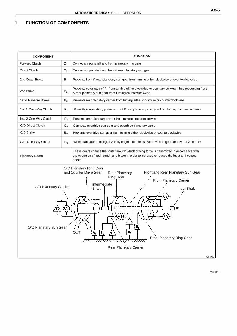
COMPONENT FUNCTION
Forward Clutch C1 Connects input shaft and front planetary ring gear
Direct Clutch C2 Connects input shaft and front & rear planetary sun gear
2nd Coast Brake B1 Prevents front & rear planetary sun gear from turning either clockwise or counterclockwise
2nd Brake B2Prevents outer race of F1 from turning either clockwise or counterclockwise, thus preventing front& rear planetary sun gear from turning counterclockwise
1st & Reverse Brake B3 Prevents rear planetary carrier from turning either clockwise or counterclockwise
No. 1 One-Way Clutch F1 When B2 is operating, prevents front & rear planetary sun gear from turning counterclockwise
No. 2 One-Way Clutch F2 Prevents rear planetary carrier from turning counterclockwise
O/D Direct Clutch C0 Connects overdrive sun gear and overdrive planetary carrier
O/D Brake B0 Prevents overdrive sun gear from turning either clockwise or counterclockwise
O/D One-Way Clutch B0 When transaxle is being driven by engine, connects overdrive sun gear and overdrive carrier
Planetary GearsThese gears change the route through which driving force is transmitted in accordance withthe operation of each clutch and brake in order to increase or reduce the input and outputspeed
AT3207
Rear Planetary Carrier
Front Planetary Ring Gear
OUTO/D Planetary Sun Gear
IN
Input ShaftO/D Planetary CarrierIntermediateShaft
Front Planetary Carrier
Rear PlanetaryRing Gear
O/D Planetary Ring Gearand Counter Drive Gear
1. FUNCTION OF COMPONENTS
V00341
Front and Rear Planetary Sun Gear
-AUTOMATIC TRANSAXLE OPERATIONAX-5

AT1097
OUT
IN
D or 2 Position 1st Gear
AT1102
OUT
IN
2 Position 2nd Gear
AT1098
OUT
/N
D Position 2nd Gear
AT1103
OUT
IN
L Position 1st Gear
AT1100
OUT
IN
D Position O/D Gear
AT1099
OUT
IN
D Position 3rd Gear
AT1101
OUT
IN
R Position Reverse Gear
Power from the engine transmitted to the input shaft via the torque converter clutch is then transmittedto the planetary gears by the operation of the clutch.By operation of the brake and one-way clutch, either the planetary carrier or the planetary sun gearare immobilized, altering the speed of revolution of the planetary gear unit.Shift change is carried out by altering the combination of clutch and brake operation.Each clutch and brake operates by hydraulic pressure; gear position is decided according to throttleopening angle and vehicle speed, and shift change automatically occurs.The conditions of operation for each gear position are shown on the following illustrations:
V02644
AX-6-AUTOMATIC TRANSAXLE OPERATION
VALVE BODY
HYDRAULIC CONTROL SYSTEM
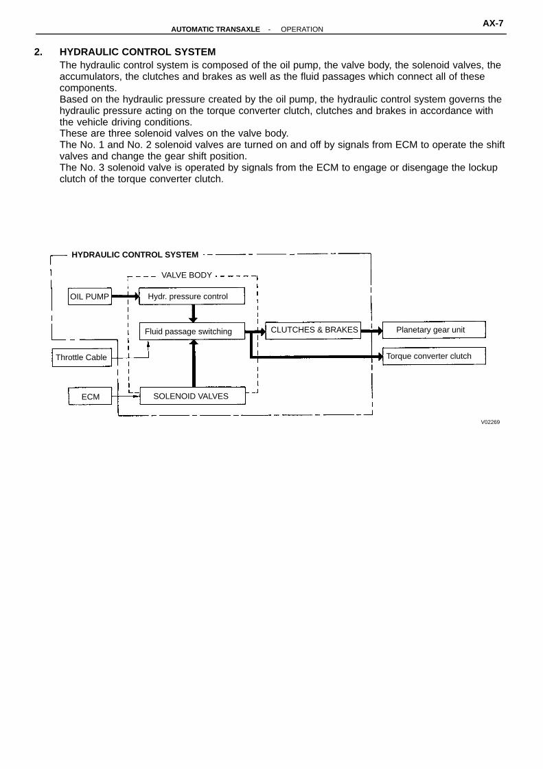
2. HYDRAULIC CONTROL SYSTEMThe hydraulic control system is composed of the oil pump, the valve body, the solenoid valves, theaccumulators, the clutches and brakes as well as the fluid passages which connect all of thesecomponents.Based on the hydraulic pressure created by the oil pump, the hydraulic control system governs thehydraulic pressure acting on the torque converter clutch, clutches and brakes in accordance withthe vehicle driving conditions.These are three solenoid valves on the valve body.The No. 1 and No. 2 solenoid valves are turned on and off by signals from ECM to operate the shiftvalves and change the gear shift position.The No. 3 solenoid valve is operated by signals from the ECM to engage or disengage the lockupclutch of the torque converter clutch.
OIL PUMP Hydr. pressure control
Fluid passage switching CLUTCHES & BRAKES Planetary gear unit
Torque converter clutchThrottle Cable
SOLENOID VALVESECM
V02269
-AUTOMATIC TRANSAXLE OPERATIONAX-7
♦ Non-reusable partQ00285: Specified torqueN-m (kgf-cm, ft-lbf)
5.4 (55.48 in.-lbf)
Manual Shift Lever
6.9 (70, 61 in.-lbf)
♦ Lock Plate
Park/Neutral PositionSwitchElbow
27 (275, 20)
♦ O-Ring ♦ O-RingCover
♦ O-Ring
2nd CoastBrake Piston
Plug
Spring
Snap Ring
♦ O-Ring
♦ O-Ring
27 (275, 20)Union
♦ O-Ring
No. 2 Vehicle SpeedSensor
Throttle Cable
♦ O-Ring
♦ GasketSolenoid Wire
Transaxle CaseUpper Cover
Union 27 (275, 20)
20 (200, 14) Breather Tube
10 (100, 7)♦ O-Ring
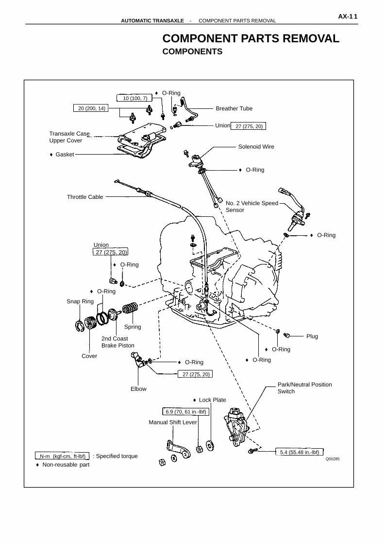
COMPONENT PARTS REMOVALCOMPONENTS
-AUTOMATIC TRANSAXLE COMPONENT PARTS REMOVALAX-1 1

N-m (kgf-cm, ft-lbf)
♦ Non-reusable part
: Specified torque Q03211
Drain Plug
♦ Gasket 4.9 (50, 43 in.-lbf)Oil Tube Bracket
Oil Pan
♦ Gasket
Oil TubeOil Tube Magnet
CoverStrainer
Manual Valve♦ Gasket
Manual Valve Body♦ Gasket♦ O-Ring
Retainer10 (100, 7)
C1 AccumulatorPiston
♦ O-Ring♦ O-Ring
B2 AccumulatorPiston
Detent SpringSpring♦ O-Ring
♦ O-Ring
B3 Apply TubeC2AccumulatorPiston
SpringParking Lock Rod♦ O-Ring Valve Body
♦ Collar
♦ Oil SealSpring
RetainingPlate
Manual ValveLever
Pin
Manual Valve Lever
♦ Second BrakeApply Gasket
Clamp
AX-12-AUTOMATIC TRANSAXLE COMPONENT PARTS REMOVAL

♦ Non-reusable part� Precoated part
Q00292N-m (kgf-cm, ft-lbf) : Specified torque
Differential CaseAssembly
19 (195, 14)
Shim
See page AX-104
LH Side BearingRetainer
♦ Lock NutOuter Race
Outer RaceOil Slinger
39 (400, 29)
♦ Gasket
Counter Drive Gear Plug
Drain Plug♦ Spacer
Sensor Rotor
Snap Ring
Filler Plug♦ Gasket
♦ GasketPlug
Bearing Cage RH Retainer
Drive Pinion 19 (195, 14)
♦ O-Ring
Drive Pinion Cap
♦ Gasket
♦ Gasket
-AUTOMATIC TRANSAXLE COMPONENT PARTS REMOVALAX-13

N-m (kgf-cm, ft-lbf)
♦ Non-reusable part
: Specified torqueQ00286
Parking Lock Panel
7.4 (75, 65 in.-lbf)
2nd Coast BrakeBand Guide
Snap Ring
BracketDisc (7 pieces)
1st and ReverseBrake Piston
ReturnSpring
♦ Second Brake Drum Gasket
♦ Gasket ♦ Gasket
O/D Brake Drum
Flange
Plate (7 pieces)
Snap RingSnap Ring
♦ O-RingSnap RingO/D Planetary Gear
ReturnSpring
DiscO/D CaseSnap Ring
Bearing
25 (250, 18)Bearing
22 (225, 16)Rear PlanetaryRing Gear
Plate2nd BrakeDrum
ThrustWasher
Flange
No. 2 One-WayClutch
ThrustWasher
Bearing
Pin Bearing
Bearing
ThrustWasher
Oil Pump
Bearing♦ O-Ring
Front PlanetaryRing Gear
ThrustWasher
ThrustWasher
Thrust Washer
Second CoastBrake Band
Drum andSun Gear
Direct ClutchForward Clutch
Front PlanetaryGear
No. 1 one-WayClutch
Rear PlanetaryGear
AX-14-AUTOMATIC TRANSAXLE COMPONENT PARTS REMOVAL

Q00254
Q00256
Q00255
Q00270
Q00272
SEPARATE BASIC SUBASSEMBLY
1. REMOVE UNION AND ELBOW(a) Remove the manual shift lever.
(b) Using the open and wrench, remove the unionand elbow.
(c) Remove the O-rings from the union and elbow.
2. REMOVE PARK/NEUTRAL POSITION SWITCH(a) Pry off the lock washer and remove the manual
valve shaft nut.
(b) Remove the two bolts and pull out the park/neu-tral position switch.
3. REMOVE THROTTLE CABLE RETAINING BOLTAND PLATE
4. REMOVE NO. 2 VEHICLE SPEED SENSOR(a) Remove the bolt and pull out the vehicle speed
sensor.
(b) Remove the O-ring from the vehicle speed sensor.
-AUTOMATIC TRANSAXLE COMPONENT PARTS REMOVALAX-15

AT0103
Q00277
Q00278
Q00279
Q00257
5. REMOVE OIL PAN AND GASKET(a) Remove the seventeen bolts.
(b) Remove the oil pan by lifting transaxle case.NOTICE: Do not turn the transaxle over as this willcontaminate the valve body with the foreign materialsin the bottom of the oil pan.(c) Place the transaxle on wooden blocks to prevent
damage to the oil tube bracket.
6. EXHAUST PARTICLES IN PANRemove the magnet and use it to collect any steelchips.Lock carefully at the chips and particles in the oil panand on magnet to anticipate what type of wear you willfind in the transaxle.� Steel (magnetic): bearing, gear and plate wear� Brass (non-magnetic): bushing wear
7. REMOVE OIL TUBE BRACKET AND STRAINER
8. REMOVE MANUAL VALVE BODY(a) Remove the two bolts and detent spring.
(b) Remove the five bolts and manual valve bodywith the manual valve.
(c) Remove the manual valve from the manual valvebody.
AX-16-AUTOMATIC TRANSAXLE COMPONENT PARTS REMOVAL

Q00258
AT3535
AT4178
AT3534Retainer
Clamp
Q03255
9. REMOVE OIL TUBES(a) Remove the bolt.
(b) Pry up both tube ends with a large screwdriverand remove the seven tubes.
10. DISCONNECT SOLENOID CONNECTORS
11. REMOVE CONNECTOR CLAMP AND TUBE RE-TAINER
12. REMOVE B3 APPLY TUBEPry up the tube with a screwdriver and remove thetube.
13. REMOVE VALVE BODY(a) Remove the ten bolts.
-AUTOMATIC TRANSAXLE COMPONENT PARTS REMOVALAX-17
Q00269
Q00579
AT3537
AT3539
AT3536
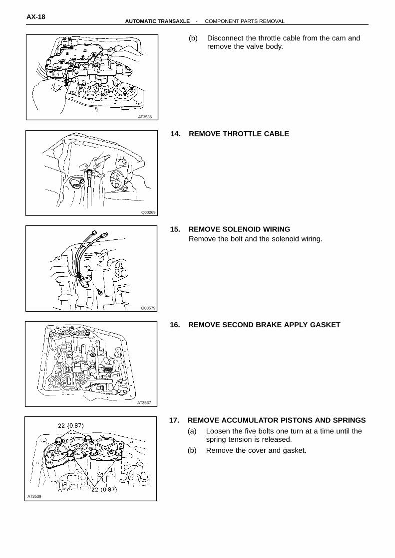
(b) Disconnect the throttle cable from the cam andremove the valve body.
14. REMOVE THROTTLE CABLE
15. REMOVE SOLENOID WIRINGRemove the bolt and the solenoid wiring.
16. REMOVE SECOND BRAKE APPLY GASKET
17. REMOVE ACCUMULATOR PISTONS AND SPRINGS(a) Loosen the five bolts one turn at a time until the
spring tension is released.
(b) Remove the cover and gasket.
AX-18-AUTOMATIC TRANSAXLE COMPONENT PARTS REMOVAL
AT3540
AT3541
AT3542
AT3543
SST
Q00291
Piston
O-Ring
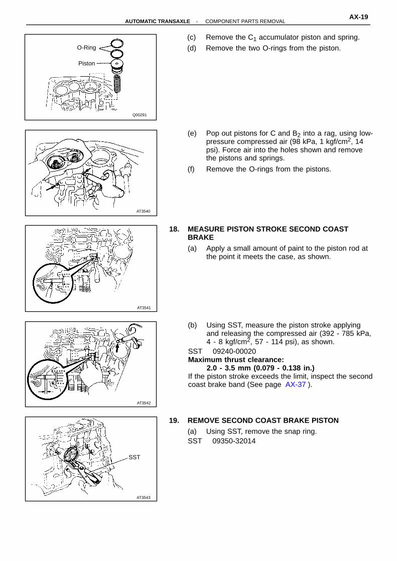
(c) Remove the C1 accumulator piston and spring.
(d) Remove the two O-rings from the piston.
(e) Pop out pistons for C and B2 into a rag, using low-pressure compressed air (98 kPa, 1 kgf/cm2, 14psi). Force air into the holes shown and removethe pistons and springs.
(f) Remove the O-rings from the pistons.
18. MEASURE PISTON STROKE SECOND COASTBRAKE(a) Apply a small amount of paint to the piston rod at
the point it meets the case, as shown.
(b) Using SST, measure the piston stroke applyingand releasing the compressed air (392 - 785 kPa,4 - 8 kgf/cm2, 57 - 114 psi), as shown.
SST 09240-00020Maximum thrust clearance:
2.0 - 3.5 mm (0.079 - 0.138 in.)If the piston stroke exceeds the limit, inspect the secondcoast brake band (See page AX-37 ).
19. REMOVE SECOND COAST BRAKE PISTON(a) Using SST, remove the snap ring.SST 09350-32014
-AUTOMATIC TRANSAXLE COMPONENT PARTS REMOVALAX-19
AT3545
AT3546
SST
AT7700
Q00259
AT3544
Cover
Piston
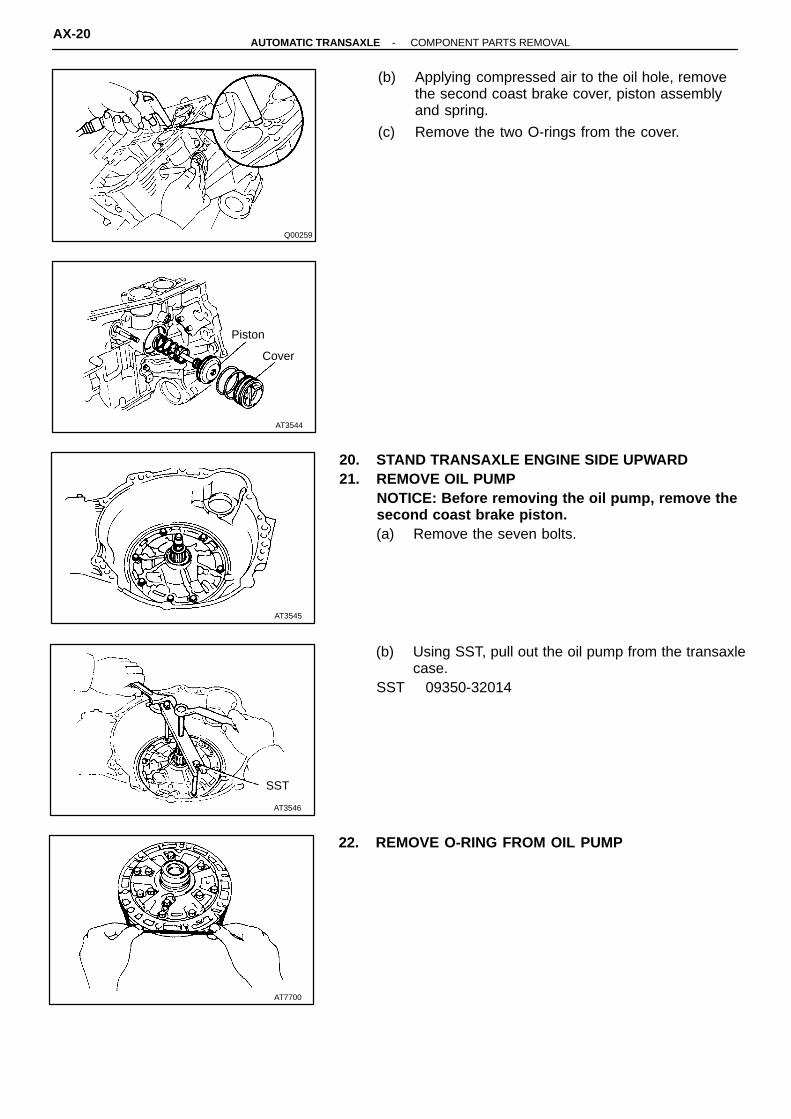
(b) Applying compressed air to the oil hole, removethe second coast brake cover, piston assemblyand spring.
(c) Remove the two O-rings from the cover.
20. STAND TRANSAXLE ENGINE SIDE UPWARD21. REMOVE OIL PUMP
NOTICE: Before removing the oil pump, remove thesecond coast brake piston.(a) Remove the seven bolts.
(b) Using SST, pull out the oil pump from the transaxlecase.
SST 09350-32014
22. REMOVE O-RING FROM OIL PUMP
AX-20-AUTOMATIC TRANSAXLE COMPONENT PARTS REMOVAL

AT3548
Forward Clutch
Thrust Washer
Direct Clutch
AT0121
AT3550
AT3549
AT3547
23. REMOVE DIRECT CLUTCH AND FORWARDCLUTCH
24. SEPARATE DIRECT CLUTCH AND FORWARDCLUTCH(a) Separate the direct clutch and forward clutch.
(b) Remove the thrust washer from direct clutch.
25. REMOVE BEARING FROM FORWARD CLUTCH
26. REMOVE SECOND COAST BRAKE BAND(a) Push the pin with a small screwdriver and remove
it from the bolt hole of the oil pump mounting.
(b) Remove the brake band.HINT: For the method of inspection, refer to page AX-37 .
27. REMOVE FRONT PLANETARY RING GEAR
-AUTOMATIC TRANSAXLE COMPONENT PARTS REMOVALAX-21

AT3600
AT3552
AT3553
AT3601
AT3551
28. REMOVE FRONT PLANETARY GEAR(a) Remove the front planetary gear.
(b) Remove the two bearings from the planetarygear.
29. REMOVE SUN GEAR AND SUN GEAR INPUT DRUM(a) Remove the sun gear and the sun gear input
drum.
(b) Remove the thrust washer from sun gear inputdrum.
30. CHECK OPERATION OF SECOND BRAKE PISTONApply compressed air into the case passage and con-firm that the piston moves.If the piston does not move, disassembly and inspect.
AX-22-AUTOMATIC TRANSAXLE COMPONENT PARTS REMOVAL

AT3556
AT3557
AT3554
AT0132
AT3555
31. REMOVE SECOND COAST BRAKE BAND GUIDE
32. REMOVE SECOND BRAKE DRUM(a) Remove the snap ring.
(b) Remove the second brake drum.
33. REMOVE SECOND BRAKE PISTON RETURNSPRING
34. REMOVE NO. 1 ONE-WAY CLUTCH
-AUTOMATIC TRANSAXLE COMPONENT PARTS REMOVALAX-23

AT7701
Q00261
Q00262
Q00263
Q00260
35. REMOVE PLATES, DISCS AND FLANGEHINT: For the method of inspection, refer to page AX-57 .
36. REMOVE SECOND BRAKE DRUM GASKETRemove the gasket.
37. REMOVE NO. 2 ONE-WAY CLUTCH AND REARPLANETARY GEAR(a) Remove the snap ring.
(b) Remove the No. 2 one-way clutch and rear plan-etary gear.
(c) Remove two thrust washers from the rear plane-tary gear.
AX-24-AUTOMATIC TRANSAXLE COMPONENT PARTS REMOVAL

AT3563
AT3602
AT3564
AT3565
AT3562
Bearing 38. REMOVE REAR PLANETARY RING GEAR(a) Remove the rear planetary ring gear.
(b) Remove the bearing from the ring gear.
39. CHECK FIRST AND REVERSE BRAKE(a) Check the operation of the first and reverse
brake piston.Apply compressed air into the case passage andconfirm that the piston moves.If the piston does not move, disassemble andinspect.
(b) Using a filler gauge, check the pack clearance ofthe first and reverse brake.
Clearance:0.85 - 2.05 mm (0.033 - 0.081 in.)
40. REMOVE FLANGE, DISCS AND PLATES OF FIRSTAND REVERSE BRAKE(a) Remove the snap ring.
(b) Remove the flange, seven discs and seven plates.HINT: For the method of inspection, refer to AX-61 .
-AUTOMATIC TRANSAXLE COMPONENT PARTS REMOVALAX-25
AT4172
AT3568
AT4177
Brake Dram
AT4168
Q00281
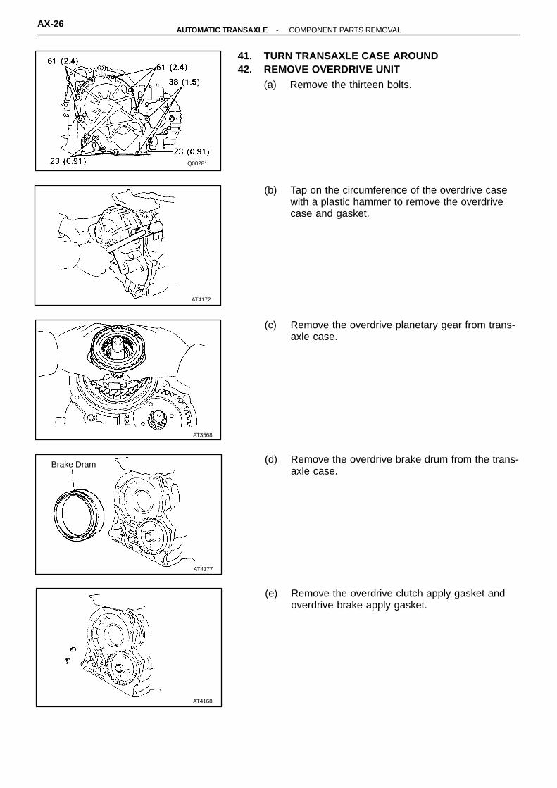
41. TURN TRANSAXLE CASE AROUND42. REMOVE OVERDRIVE UNIT
(a) Remove the thirteen bolts.
(b) Tap on the circumference of the overdrive casewith a plastic hammer to remove the overdrivecase and gasket.
(c) Remove the overdrive planetary gear from trans-axle case.
(d) Remove the overdrive brake drum from the trans-axle case.
(e) Remove the overdrive clutch apply gasket andoverdrive brake apply gasket.
AX-26-AUTOMATIC TRANSAXLE COMPONENT PARTS REMOVAL

AT0194
SST
AT3571
AT0196
AT2725
AT0376
SST
43. REMOVE FIRST AND REVERSE BRAKE PISTON(a) Remove the piston return spring.� Place SST, compress the return spring evenly
by tightening the bolt gradually.SST 09350-32014 (09351-32040)
� Using snap ring pliers, remove the snap ring.� Remove SST.� Remove the return spring from the case.
(b) Apply compressed air into the passage of thecase to remove the piston.
HINT: Hold the piston so it is not slanted and blow withthe gun slightly away from the oil hole.
(c) If the piston does not pop out with compressedair, use needle-nose pliers to remove it.
(d) Remove the two O-rings from the piston.
-AUTOMATIC TRANSAXLE COMPONENT PARTS REMOVALAX-27
AT3573
AT3575
AT3574
AT2725
AT0147
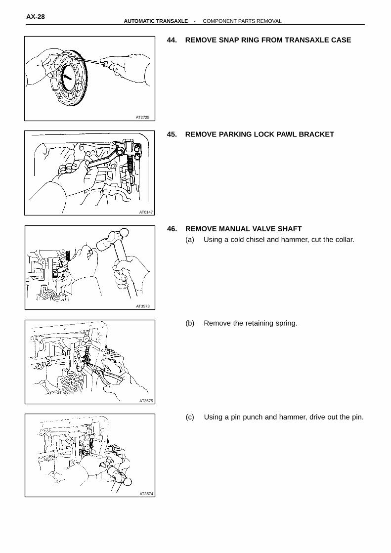
44. REMOVE SNAP RING FROM TRANSAXLE CASE
45. REMOVE PARKING LOCK PAWL BRACKET
46. REMOVE MANUAL VALVE SHAFT(a) Using a cold chisel and hammer, cut the collar.
(b) Remove the retaining spring.
(c) Using a pin punch and hammer, drive out the pin.
AX-28-AUTOMATIC TRANSAXLE COMPONENT PARTS REMOVAL

AT3577
AT2731Lock Pawl
Pin
Valve LeverManual
ParkingLock Rod
AT3576
(d) Slide out the shaft from the transaxle case andremove the manual valve lever and parking lockrod.
47. REMOVE MANUAL VALVE SHAFT OIL SEALUsing a screwdriver, remove the oil seal.
48. REMOVE PIN, SPRING AND PARKING LOCK PAWL
-AUTOMATIC TRANSAXLE COMPONENT PARTS REMOVALAX-29

AT4170
AT4174
AT3581
AT3582
AT4171
DIFFERENTIAL COMPONENT PARTS REMOVAL
1. MEASURE DIFFERENTIAL TOTAL PRELOADUsing a torque meter, measure the total preload andmake a note of it.
2. REMOVE LH BEARING RETAINER(a) Remove the six bolts.
(b) Using a large screwdriver, remove the LH bearingretainer.
NOTICE: Wrap the screwdriver in a rag, etc. to avoiddamage to the case and retainer.
3. REMOVE RH RETAINER(a) Remove the six bolts.
(b) Using a large screwdriver, remove the RH retainer.NOTICE: Wrap the screwdriver in a rag, etc. to avoiddamage to case and retainer.
AX-30-AUTOMATIC TRANSAXLE COMPONENT PARTS REMOVAL
AT4232
AT3585
AT3586
C00264
Q00282
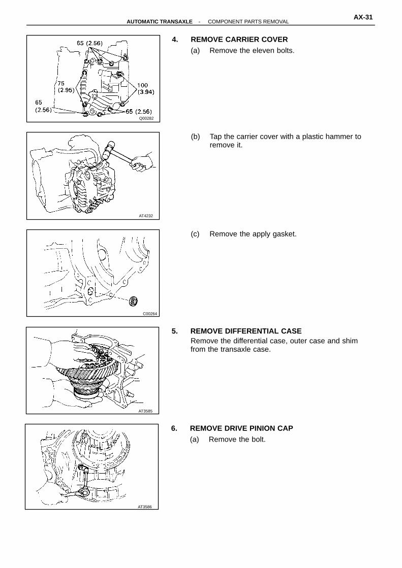
4. REMOVE CARRIER COVER(a) Remove the eleven bolts.
(b) Tap the carrier cover with a plastic hammer toremove it.
(c) Remove the apply gasket.
5. REMOVE DIFFERENTIAL CASERemove the differential case, outer case and shimfrom the transaxle case.
6. REMOVE DRIVE PINION CAP(a) Remove the bolt.
-AUTOMATIC TRANSAXLE COMPONENT PARTS REMOVALAX-31

AT3588
AT3589
AT3590SST
AT3591
SST
AT3587
(b) Using pliers, pull out the drive pinion cap.
(c) Remove the O-rings from the cap.
7. MEASURE DRIVE PINION PRELOADUsing a torque meter, measure the drive pinion pre-load.Preload (at starting):Reused bearing
0.5 - 0.8 N-m (5 - 8 kgf-cm, 4.3 - 6.9 in.-lbf)The total preload measured in step 1 minus the drivepinion preload equals 0.1 - 0.2 N-m (1.3 - 2.0 kgf-cm,1.1 - 1.7 in.-lbf). If the result is not within this specifi-cation, the side bearing preload is bad.
8. REMOVE COUNTER DRIVEN GEAR
(a) Using a chisel, loosen the staked part of the nut.
(b) Using SST to hold the gear, remove the nut.SST 09330-00021, 09350-32014 (09351-32032)
(c) Using SST, remove the gear and bearing.SST 09350-32014 (09351-32061)
AX-32-AUTOMATIC TRANSAXLE COMPONENT PARTS REMOVAL

AT3593
Oil Slinger
Spacer
AT3595
SST
AT3596
AT3594
AT3592
SST
9. REMOVE OUTER RACE, SPACER AND OIL SLINGER(a) Using SST, remove the outer race.SST 09350-32014 (09308-10010)
(b) Remove the spacer and oil slinger.
10. REMOVE SENSOR ROTOR
11. REMOVE DRIVE PINION(a) Using SST, remove the snap ring.SST 09350-32014 (09351-32050)
(b) Install the bar into the case hole to drive out thedrive pinion.
(c) Using a press, drive out the drive pinion fromtransaxle case.
-AUTOMATIC TRANSAXLE COMPONENT PARTS REMOVALAX-33

Q00265
(d) Remove the bearing cage from drive pinion.
AX-34-AUTOMATIC TRANSAXLE COMPONENT PARTS REMOVAL

1. GENERAL CLEANING NOTES:(a) All disassembled parts should be washed clean and any fluid passages and holes blown through
with compressed air.
(b) When using compressed air to dry parts, always aim away from yourself to prevent accidentallyspraying automatic transaxle fluid or kerosene in your face.
(c) The recommended automatic transaxle fluid or kerosene should be used for cleaning.2. PARTS ARRANGEMENT:
(a) After cleaning, the parts should be arranged in the correct order to allow efficient inspection, repairs, and reassembly.
(b) When disassembling a valve body, be sure to keep each valve together with the correspondingspring.
(c) New brakes and clutches that are to be used for replacement must be soaked in transaxle fluid forat least fifteen minutes before assembly.
3. GENERAL ASSEMBLY:(a) All oil seal rings, clutch discs, clutch plates, rotating parts, and sliding surfaces should be coated
with transmission fluid prior to reassembly.
(b) All gaskets and rubber O-rings should be replaced.
(c) Make sure that the ends of a snap ring are not aligned with one of the cutouts and are installed inthe groove correctly.
(d) If a worn bushing is to be replaced, the subassembly containing that bushing must be replaced.
(e) Check thrust bearings and races for wear or damage. Replace if necessary.
(f) Use petroleum jelly to keep parts in place.
GENERAL NOTES
The instructions here are organized so that you work on only one component group at a time.This will help avoid confusion from similar-looking parts of different subassemblies being onyour workbench at the same time.The component groups are inspected and repaired from the converter housing side.As much as possible, complete the inspection, repair and assembly before proceeding to thenext component group. If a component group can not be assembled because parts are beingordered, be sure to keep all parts off that group in a separate container while proceeding withdisassembly, inspection, repair and assembly of other component groups.Recommended fluid for the automatic transaxle:
ATF DEXRON� II
-AUTOMATIC TRANSAXLE COMPONENT PARTS REMOVALAX-35
AT7702
AT7703
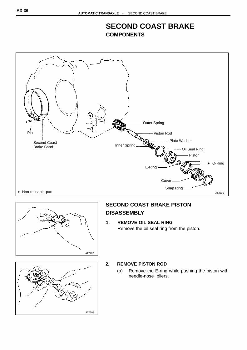
AT3606♦ Non-reusable partSnap Ring
Cover
E-Ring♦ O-Ring
Piston
Oil Seal Ring
Second CoastBrake Band Inner Spring
Plate Washer
Pin Piston Rod
Outer Spring
SECOND COAST BRAKECOMPONENTS
SECOND COAST BRAKE PISTON
DISASSEMBLY
1. REMOVE OIL SEAL RINGRemove the oil seal ring from the piston.
2. REMOVE PISTON ROD(a) Remove the E-ring while pushing the piston with
needle-nose pliers.
AX-36-AUTOMATIC TRANSAXLE SECOND COAST BRAKE

AT3607
Printed Mark
AT7705
AT7704
Piston Rod
Inner SpringPlate Washer
AT7704
Piston Rod
Inner SpringPlate Washer(b) Remove the inner spring, plate washer and piston
rod.
SECOND COAST BRAKE COMPONENT
INSPECTION
If the lining of the brake band is peeling off or discol-ored, or even part of the printed marks is defaced, re-place the brake band.
SECOND COAST BRAKE PISTON
ASSEMBLY
1. SELECT PISTON RODIf the band is OK but piston stroke not within the standardvalue, select a new piston rod.Piston stroke:
2.0 - 3.5 mm (0.079 - 0.138 in.)There are two lengths of piston rod.Piston rod length:
95.2 mm (3.748 in.)96.3 mm (3.791 in.)
2. INSTALL PISTON ROD(a) Install the plate washer and inner spring to the
piston rod.
-AUTOMATIC TRANSAXLE SECOND COAST BRAKEAX-37

AT7707
Less than5 mm (0.20 in.)
AT7706
(b) Install the E-ring while pushing the piston.
3. INSTALL OIL SEAL RING(a) Apply ATF to the oil seal ring.
(b) Install the oil seal ring to the piston.NOTICE: Do not spread the ring ends more than nec-essary.
AX-38-AUTOMATIC TRANSAXLE SECOND COAST BRAKE

AT3609
♦ Non-reusable part
N-m (kgf-cm, ft-lbf) : Specified torqueAT3608
♦ O-Ring
♦ Oil Seal
Drive GearThrust Washer
Oil Seal Ring
Driven Gear
Pump Body Stator Shaft
10 (100, 7)
AT3610
OIL PUMPCOMPONENTS
OIL PUMP DISASSEMBLY
1. REMOVE OIL SEAL RINGSRemove the two oil seal rings from the stator shaftback side.
2. REMOVE THRUST WASHER FROM STATOR SHAFTBACK SIDE
-AUTOMATIC TRANSAXLE OIL PUMPAX-39

AT2732
AT0153
AT0154
AT3611
3. REMOVE STATOR SHAFTRemove the eleven bolts and stator shaft.HINT: Keep the gears in assembly order.
4. REMOVE FRONT OIL SEALPry off the oil seal with a screwdriver.
OIL PUMP BUSHING INSPECTION
1. CHECK BODY CLEARANCE OF DRIVEN GEARPush the driven gear to one side of the body.Using a feeler gauge, measure the clearance.Standard body clearance:
0.07 - 0.15 mm (0.0028 - 0.0059 in.)Maximum body clearance:
0.3 mm (0.012 in.)If the body clearance is greater than the maximum, re-place the oil pump body subassembly.
2. CHECK TIP CLEARANCE OF DRIVEN GEARMeasure between the driven gear teeth and the cres-cent-shaped part of the pump body.Standard tip clearance:
0.11 - 0.14 mm (0.0043 - 0.0055 in.)Maximum tip clearance:
0.3 mm (0.012 in.)If the tip clearance is greater than the maximum, re-place the oil pump body subassembly.
AX-40-AUTOMATIC TRANSAXLE OIL PUMP

AT7708
AT3612
AT0156
SST
Mark Thickness mm (in.)
A 9.440 - 9.456 (0.3717 - 0.3723)
B 9.456 - 9.474 (0.3723 - 0.3730)
C 9.474 - 9.490 (0.3730 - 0.3736)
AT0155
3. CHECK SIDE CLEARANCE OF BOTH GEARSUsing a steel straightedge and a feeler gauge, mea-sure the side clearance of both gears.Standard side clearance:
0.002 - 0.005 mm (0.0008 - 0.0020 in.)Maximum side clearance:
0.1 mm (0.004 in.)There are three different thickness for drive and drivengears.Drive and driven gear thickness:
If the thickest gear can not make the side clearancewithin standard specification, replace the oil pump bodysubassembly.
4. CHECK OIL PUMP BODY BUSHINGUsing a dial indicator, measure the inside diameter ofthe oil pump body bushing.Maximum inside diameter:
38.18 mm (1.5031 in.)If the inside diameter is greater than the maximum, re-place the oil pump body subassembly.
5. CHECK STATOR SHAFT BUSHINGUsing a dial indicator, measure the inside diameter statorshaft bushing.Maximum inside diameter:
21.57 mm (0.8492 in.)If the inside diameter is greater than the maximum, re-place the stator shaft.
OIL PUMP ASSEMBLY
1. INSTALL FRONT OIL SEALUsing SST and a hammer, install a new oil seal. Theseal end should be flush with the outer edge of thepump body.SST 09350-32014 (09351-32140)
-AUTOMATIC TRANSAXLE OIL PUMPAX-41

AT3611
AT3609
AT3610
AT0161
AT0157
2. INSTALL DRIVEN GEAR AND DRIVE GEARMake sure the top of the gears are facing upward.
3. INSTALL STATOR SHAFT TO PUMP BODY(a) Align the stator shaft with each bolt hole.
(b) Torque the eleven bolts.Torque: 10 N-m (100 kgf-cm, 7 ft-lbf)
4. INSTALL THRUST WASHER(a) Coat the thrust washer with petroleum jelly.
(b) Align the tab of the washer with the hollow of thepump body.
5. INSTALL OIL SEAL RINGSInstall the two oil seal rings to the stator shaft backside.NOTICE: Do not spread the ring ends more than nec-essary.HINT: After installing the oil seal rings, check that theymove smoothly.
6. CHECK PUMP DRIVE GEAR ROTATIONTurn the drive gear with two screwdrivers and makesure it rotates smoothly.NOTICE: Be careful not to damage the oil seal lip.
AX-42-AUTOMATIC TRANSAXLE OIL PUMP

AT7710
AT7709
SST
♦ Non-reusable part
AT3613Plate
Disc
Flange
Snap RingThrust Washer
Clutch Drum
Piston
♦ O-Ring Snap Ring
Piston ReturnSpring
DIRECT CLUTCHCOMPONENTS
DIRECT CLUTCH DISASSEMBLY
1. CHECK PISTON STROKE OF DIRECT CLUTCH(a) Install the direct clutch on the oil pump.
(b) Using a dial indicator (long type pick or SST),measure the direct clutch piston stroke applyingand releasing the compressed air (392 - 785kPa, 4 - 8 kg/cm2, 57-114 psi), as shown.
SST 09350-32014 (09351-32190)Piston stroke:
0.91 - 1.35 mm (0.0358 - 0.0531 in.)If the piston stroke is greater than the maximum, in-spect each component.
-AUTOMATIC TRANSAXLE DIRECT CLUTCHAX-43

AT2733
SST
AT3614
AT0165
AT2735
AT0163
2. REMOVE SNAP RING FROM CLUTCH DRUM3. REMOVE FLANGE, DISCS AND PLATES
4. REMOVE PISTON RETURN SPRING(a) Place SST on the spring retainer and compress
the springs with a shop press.SST 09350-32014 (09351-32070)(b) Remove the snap ring with snap ring pliers.
(c) Remove the piston return spring.
5. REMOVE CLUTCH PISTON(a) Install the direct clutch onto the oil pump.
(b) Apply compressed air to the oil pump to removethe piston. (If the piston does not come out com-pletely, use needle-nose plies to remove it.)
(c) Remove the direct clutch from the oil pump.
(d) Remove the two O-rings from the piston.
AX-44-AUTOMATIC TRANSAXLE DIRECT CLUTCH

Q00365
PrintedNumbers
AT3231
AT0168
AT3614
Z00365AT3639 AT3640
DIRECT CLUTCH INSPECTION
1. INSPECT CLUTCH PISTON(a) Check that the check ball is free by shaking the
piston.
(b) Check that the valve does not leak by applyinglow-pressure compressed air.
2. INSPECT DISCS, PLATES AND FLANGECheck if the sliding surfaces of the discs, plates andflange are worn or burnt. If necessary, replace them.HINT:� If the lining of the disc is peeling off or discolored,
or even a part of the printed numbers are de-faced, replace all discs.
� Before assembling new discs, soak them in ATFfor at least fifteen minutes.
3. CHECK DIRECT CLUTCH BUSHINGUsing a dial indicator, measure the inside diameter ofthe direct clutch bushing.Maximum inside diameter:
48.27 mm (1.9004 in.)If the inside diameter is greater than the maximum, re-place the direct clutch.
DIRECT CLUTCH ASSEMBLY
1. INSTALL CLUTCH PISTON IN DIRECT CLUTCHDRUM(a) Install new O-rings to the piston. Coat the O-rings
with ATF.
(b) Being careful not to damage the O-rings, pressthe piston into the drum with the cup side up.
2. INSTALL PISTON RETURN SPRING(a) Place the return spring and snap ring onto the
piston.
-AUTOMATIC TRANSAXLE DIRECT CLUTCHAX-45
AT3617
PlateDisc
Flange
A241E
AT0171
AT7709
SST
AT7710
AT2733
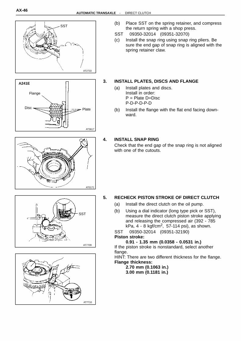
SST(b) Place SST on the spring retainer, and compress
the return spring with a shop press.SST 09350-32014 (09351-32070)(c) Install the snap ring using snap ring pliers. Be
sure the end gap of snap ring is aligned with thespring retainer claw.
3. INSTALL PLATES, DISCS AND FLANGE(a) Install plates and discs.
Install in order:P = Plate D=DiscP-D-P-D-P-D
(b) Install the flange with the flat end facing down-ward.
4. INSTALL SNAP RINGCheck that the end gap of the snap ring is not alignedwith one of the cutouts.
5. RECHECK PISTON STROKE OF DIRECT CLUTCH(a) Install the direct clutch on the oil pump.
(b) Using a dial indicator (long type pick or SST),measure the direct clutch piston stroke applyingand releasing the compressed air (392 - 785kPa, 4 - 8 kgf/cm2, 57-114 psi), as shown.
SST 09350-32014 (09351-32190)Piston stroke:
0.91 - 1.35 mm (0.0358 - 0.0531 in.)If the piston stroke is nonstandard, select anotherflange.HINT: There are two different thickness for the flange.Flange thickness:
2.70 mm (0.1063 in.)3.00 mm (0.1181 in.)
AX-46-AUTOMATIC TRANSAXLE DIRECT CLUTCH

AT3620
♦ Non-reusable part
Q00283
Plate
Flange
Disc
Snap Ring
ReturnSpring
Oil SealRing
BearingPiston
Bearing Snap RingClutch Drum♦ O-Ring
Q00274
SST
FORWARD CLUTCHCOMPONENTS
FORWARD CLUTCH DISASSEMBLY
1. CHECK PISTON STROKE OF FORWARD CLUTCHUsing a dial indicator (long type pick or SST), measurethe forward clutch piston stroke applying and releasingthe compressed air (392 - 785 kPa, 4 - 8 kgf/cm2, 57- 114 psi), as shown.SST 09350-32014 (09351-32190)Piston stroke:
1.79 - 2.21 mm (0.0705 - 0.0870 in.)If the piston stroke is greater than the maximum, in-spect each component.
-AUTOMATIC TRANSAXLE FORWARD CLUTCHAX-47

AT2738
AT0177
SST
AT3621
AT3622
AT0176
2. REMOVE SNAP RING FROM CLUTCH DRUM
3. REMOVE FLANGE, DISCS AND PLATES
4. REMOVE RETURN SPRING(a) Place SST on the spring retainer and compress
the springs with a shop press.SST 09350-32014 (09351-32070)(b) Using snap ring plies, remove the snap ring.
(c) Remove the return spring.
5. REMOVE CLUTCH PISTON(a) Apply compressed air into the oil passage to
remove the piston.If the piston does not come out, use needle-nosepliers to remove it.
AX-48-AUTOMATIC TRANSAXLE FORWARD CLUTCH
AT3623
Oil Seal Ring
Z00366AT0179 AT0180
Q00362
PrintedNumbers
AT3623
Oil Seal Ring
AT2735
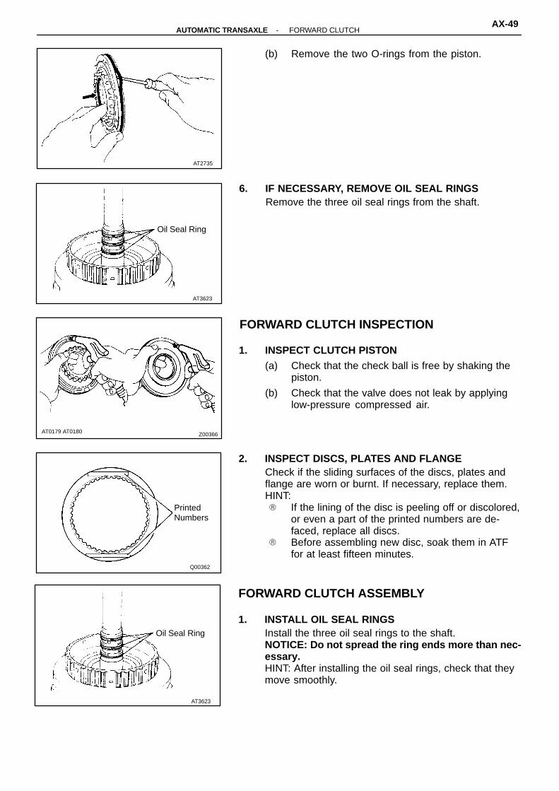
(b) Remove the two O-rings from the piston.
6. IF NECESSARY, REMOVE OIL SEAL RINGSRemove the three oil seal rings from the shaft.
FORWARD CLUTCH INSPECTION
1. INSPECT CLUTCH PISTON(a) Check that the check ball is free by shaking the
piston.
(b) Check that the valve does not leak by applyinglow-pressure compressed air.
2. INSPECT DISCS, PLATES AND FLANGECheck if the sliding surfaces of the discs, plates andflange are worn or burnt. If necessary, replace them.HINT:� If the lining of the disc is peeling off or discolored,
or even a part of the printed numbers are de-faced, replace all discs.
� Before assembling new disc, soak them in ATFfor at least fifteen minutes.
FORWARD CLUTCH ASSEMBLY
1. INSTALL OIL SEAL RINGSInstall the three oil seal rings to the shaft.NOTICE: Do not spread the ring ends more than nec-essary.HINT: After installing the oil seal rings, check that theymove smoothly.
-AUTOMATIC TRANSAXLE FORWARD CLUTCHAX-49

AT0182
AT0177
SST
Q00275
Plate
DiscFlange
AT7713
AT2736
2. INSTALL CLUTCH PISTON TO CLUTCH DRUM(a) Install the two new O-rings to the piston.
(b) Coat the O-ring with ATF.
(c) Press the piston into the drum with the cup side up,being careful not to damage the O-rings.
3. INSTALL PISTON RETURN SPRINGS(a) Place the return spring and snap ring onto the
piston.
(b) Place SST on the spring retainer, and compressthe springs with a shop press.
SST 09350-32014 (09351-32070)(c) Install the snap ring with snap ring pliers.
Be sure the end gap of the snap ring is notaligned with the spring retainer claw.
4. INSTALL PLATES, DISCS AND FLANGE(a) Install the plates and discs.
Install in order:P = Plate D = DiscP-D-P-D-P-D-P-D-P-D
(b) Install the flange with the flat end facing downward.
5. INSTALL SNAP RINGCheck that the end gap of snap ring is not aligned withone of the cutouts.
AX-50-AUTOMATIC TRANSAXLE FORWARD CLUTCH

AT3620
Q00274
SST
6. RECHECK PISTON STROKE OF FORWARD CLUTCHUsing a dial indicator (long type pick or SST), measurethe forward clutch piston stroke applying and releasingthe compressed air (392 - 785 kPa, 4 - 8 kgf/cm2, 57 -114 psi), as shown.SST 09350-32014 (09351-32190)Piston stroke:
1.79 - 2.21 mm (0.0705 - 0.0870 in.)If the piston stroke is nonstandard, select another flange.HINT: There are two different thicknesses for the flange.Flange thickness:
2.30 mm (0.0906 in.)2.70 mm (1.0630 in.)
-AUTOMATIC TRANSAXLE FORWARD CLUTCHAX-51
AT0185
Turn
FreeHold
Lock
AT0186
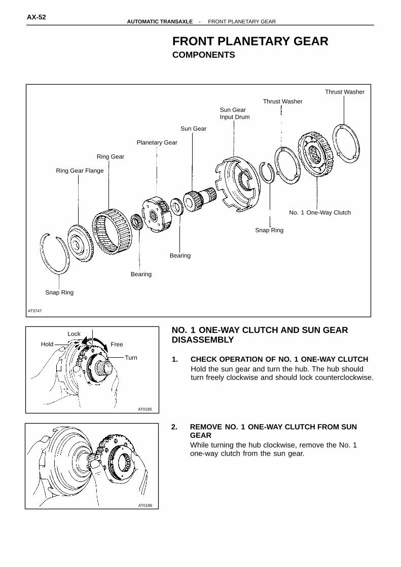
AT3747
Snap Ring
Bearing
Bearing
Snap Ring
No. 1 One-Way Clutch
Ring Gear Flange
Ring Gear
Planetary Gear
Sun Gear
Sun GearInput Drum
Thrust Washer
Thrust Washer
NO. 1 ONE-WAY CLUTCH AND SUN GEAR DISASSEMBLY
FRONT PLANETARY GEARCOMPONENTS
1. CHECK OPERATION OF NO. 1 ONE-WAY CLUTCHHold the sun gear and turn the hub. The hub shouldturn freely clockwise and should lock counterclockwise.
2. REMOVE NO. 1 ONE-WAY CLUTCH FROM SUNGEARWhile turning the hub clockwise, remove the No. 1one-way clutch from the sun gear.
AX-52-AUTOMATIC TRANSAXLE FRONT PLANETARY GEAR

AT2739
AT2739
AT3629
AT3628
AT3628
3. REMOVE THRUST WASHER FROM SUN GEAR INPUTDRUM
4. REMOVE SUN GEAR FROM DRUM(a) Using snap ring plies, remove the snap ring from
the drum.
(b) Remove the sun gear from the drum.
5. CHECK SUN GEAR BUSHINGSUsing a dial indicator, measure the inside diameter ofthe sun gear bushings.Maximum inside diameter:
22.59 mm (0.08894 in.)If the inside diameter is greater then the maximum, re-place the sun gear.
NO. 1 ONE-WAY CLUTCH AND SUN GEAR ASSEMBLY
1. INSTALL SUN GEAR TO DRUM(a) Install the sun gear to the drum.
(b) Using snap ring plies, install the snap ring to drum.
2. INSTALL THRUST WASHER TO SUN GEAR INPUTDRUM
-AUTOMATIC TRANSAXLE FRONT PLANETARY GEARAX-53

AT2741
AT7714
AT7715
AT7714
AT0185
Turn
FreeHold
Lock
PLANETARY RING GEAR INSPECTION
3. INSTALL NO. 1 ONE-WAY CLUTCH ON SUN GEARWhile turning the hub clockwise, slide the No. 1 one-way clutch onto the sun gear.
4. RECHECK OPERATION OF NO. 1 ONE-WAYCLUTCH
1. INSPECT RING GEAR FLANGE BUSHINGUsing a dial indicator, measure the inside diameter ofthe flange bushing.Maximum inside diameter:
30.08 mm (1.1842 in.)If the inside diameter is greater then the maximum,replace the flange.
2. REMOVE RING GEAR FLANGE(a) Using a screwdriver, remove the snap ring.
(b) Remove the flange from the ring gear.
3. INSTALL RING GEAR FLANGE(a) Position the flange into the ring gear.
(b) Using a screwdriver, install the snap ring.
AX-54-AUTOMATIC TRANSAXLE FRONT PLANETARY GEAR

AT4306
FRONT PLANETARY GEAR INSPECTION
MEASURE PLANETARY PINION GEAR THRUSTCLEARANCEUsing a feeler gauge, measure the planetary pinion gearthrust clearance.Standard clearance:
0.16 - 0.56 mm (0.0063 - 0.0220 in.)Maximum clearance:
0.61 mm (0.0240 in.)If the clearance is greater than the maximum, replacethe planetary gear assembly.
-AUTOMATIC TRANSAXLE FRONT PLANETARY GEARAX-55
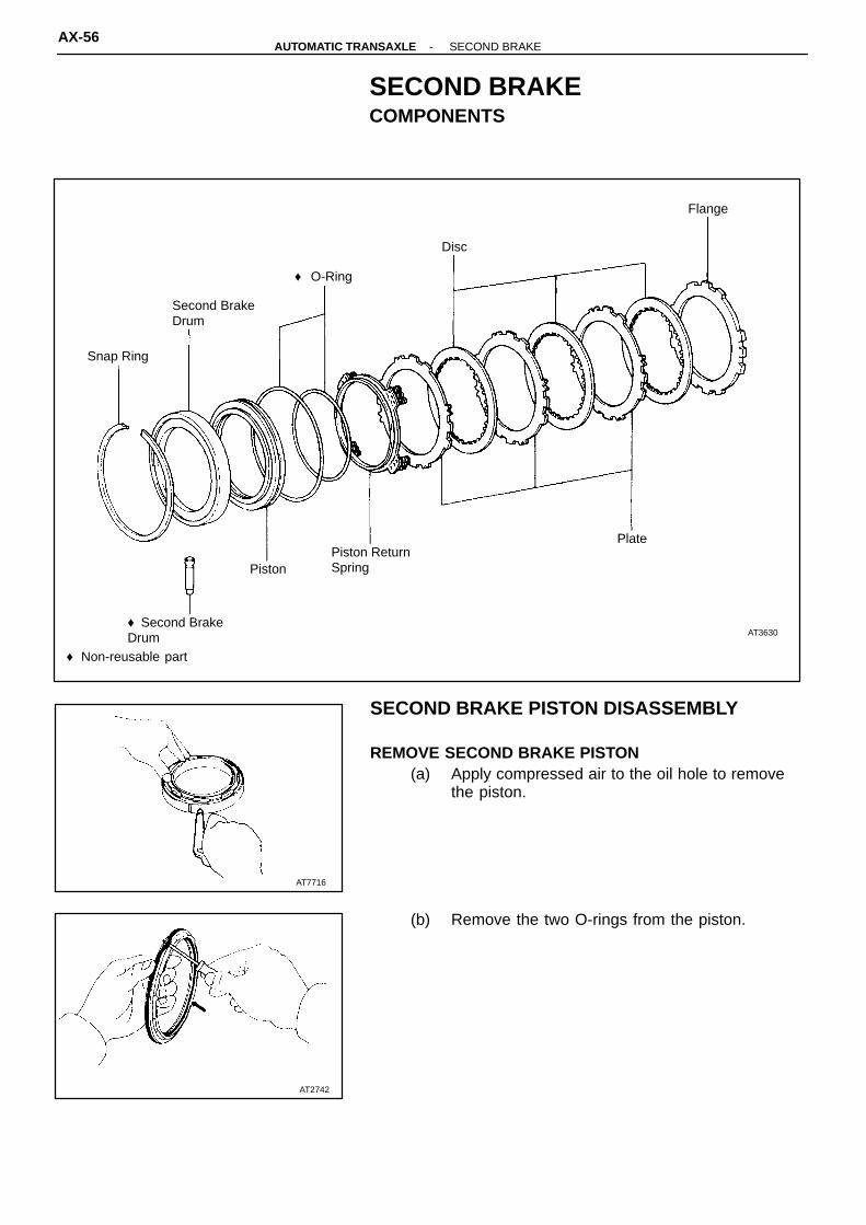
AT7716
AT2742
AT3630♦ Second BrakeDrum
PistonPiston ReturnSpring
Plate
Snap Ring
Second BrakeDrum
♦ O-Ring
Disc
Flange
♦ Non-reusable part
SECOND BRAKE PISTON DISASSEMBLY
SECOND BRAKECOMPONENTS
REMOVE SECOND BRAKE PISTON(a) Apply compressed air to the oil hole to remove
the piston.
(b) Remove the two O-rings from the piston.
AX-56-AUTOMATIC TRANSAXLE SECOND BRAKE

AT2744
AT2743
Q00365
PrintedNumbers
SECOND BRAKE COMPONENT INSPECTION
INSPECT DISCS, PLATES AND FLANGECheck if the sliding surfaces of the discs, plates andflange are worn or burnt. If necessary, replace them.HINT:� If the lining of the disc is peeling off or discolored,
or even a part of the printed numbers are defaced,replace all discs.
� Before assembling new discs, soak them in ATFfor at least fifteen minutes.
SECOND BRAKE PISTON ASSEMBLY
INSTALL PISTON(a) Coat a new O-ring with ATF.
(b) Install the two O-rings on the piston.
(c) Press the piston into the drum, being careful notto damage the O-rings.
-AUTOMATIC TRANSAXLE SECOND BRAKEAX-57

AT0191
Turn
Hold Free Lock
Q00363
Align
Q00293Snap Ring
Retainer
Retainer
Snap Ring
Thrust Washer
Bearing
Flange
No. 2 One-WayClutch
Outer Race
Rear PlanetaryGear
Ring Gear
Snap Ring
NO. 2 ONE-WAY CLUTCH DISASSEMBLY
REAR PLANETARY GEARCOMPONENTS
1. CHECK OPERATION OF NO. 2 ONE-WAY CLUTCHHold the outer race and turn the rear planetary gear.The rear planetary gear should turn freely counter-clockwise and should lock clockwise.
2. SEPARATE NO. 2 ONE-WAY CLUTCH AND REARPLANETARY GEAR
3. REMOVE THRUST WASHERRemove the thrust washer from the rear side of plane-tary gear.
AX-58-AUTOMATIC TRANSAXLE REAR PLANETARY GEAR

Q00366
AT0193
Outer Race
Flanged Side
Shiny Side
AT0192
AT0192
NO. 2 ONE-WAY CLUTCH ASSEMBLY
4. REMOVE NO. 2 ONE-WAY CLUTCH FROM OUTERRACE(a) Remove the two snap rings and retainers from
both sides.
(b) Remove the No. 2 one-way clutch from the outerrace.
REAR PLANETARY GEAR INSPECTION
MEASURE PLANETARY PINION GEAR THRUSTCLEARANCEUsing a feeler gauge, measure the planetary piniongear thrust clearance.Standard clearance:
0.16 - 0.56 mm (0.0063 - 0.0220 in.)Maximum clearance:
0.61 mm (0.0240 in.)If the clearance is greater than the maximum, replacethe planetary gear assembly.
1. INSTALL ONE-WAY CLUTCH(a) Install the No. 2 one-way clutch into the outer
race, facing the flanged side of the No. 2 one-way clutch toward the shiny side of the outerrace.
(b) Install the two retainers and snap rings to bothsides.
-AUTOMATIC TRANSAXLE REAR PLANETARY GEARAX-59

AT0191
Turn
Hold Free Lock
Q00363
Align
AT7717
AT4235
Q00361
Black Side
2. INSTALL PLANETARY GEAR INTO NO. 2 ONE-WAYCLUTCHInstall the planetary gear into the No. 2 one-way clutch,facing the inner race of the rear planetary gear towardthe black side of the No. 2 one-way clutch outer race.
3. CHECK OPERATION OF NO. 2 ONE-WAY CLUTCH
4. INSTALL THRUST WASHER(a) Coat the thrust washer with petroleum jelly.
(b) Align the tab of the washer with the hollows ofthe carrier.
RING GEAR FLANGE REPLACEMENT
1. REMOVE RING GEAR FLANGE(a) Using a screwdriver, remove the snap ring.
(b) Remove the flange from the ring gear.
2. INSTALL RING GEAR FLANGE(a) Position the flange into the ring gear.
(b) Using a screwdriver, install the snap ring.
AX-60-AUTOMATIC TRANSAXLE REAR PLANETARY GEAR

♦ Non-reusable part
AT3632
Snap Ring
DiscPiston Return Spring
PistonSnap Ring♦ O-Ring
Flange
Plate
Q00376
PrintedNumbers
FIRST AND REVERSE BRAKECOMPONENTS
FIRST AND REVERSE BRAKECOMPONENTS INSPECTION
INSPECT DISCS, PLATES AND FLANGESCheck if the sliding surfaces of the discs, plates andflanges are worn or burnt. If necessary, replace them.HINT:� If the lining of the disc is peeling off or discolored,
or even a part of the printed numbers are defaced,replace all discs.
� Before assembling new discs, soak them in ATFfor at least fifteen minutes.
-AUTOMATIC TRANSAXLE FIRST AND REVERSE BRAKEAX-61

♦ Non-reusable part
AT5051Rear Bearing
O/D Planetary GearOil Seal RingNo. 3 Thrust Washer
One-W ay Clutch Outer RaceIntermediate Shaft
Retainer
Retaining PlateAdjust Nut
Intermediate Shaft Bearing Snap RingOuter Race
Counter Driven Gear
Outer Race O/D One-Way ClutchPlug
Locking Washer O/D PlanetaryRing Gear
Front Bearing
♦ O-Ring
Snap Ring
Snap RingFlange
Plate Snap Ring
Piston ReturnSpring
BearingBearing
RaceSnap Ring
DiscO/D Case
C0 PistonSnap Ring
Cushion Plate ♦ O-RingPlate
C0 DrumDiscOil Seal Ring
Piston Return Spring
O/D Brake Drum
♦ O-RingFlangeO/D Brake Piston
C0 Accumulator Piston
Spring
Retaining Plate
Snap Ring
OVERDRIVE UNITCOMPONENTS
AX-62-AUTOMATIC TRANSAXLE OVERDRIVE UNIT

AT2523
AT2745
AT7719
AT3063
OVERDRIVE BRAKE DISASSEMBLY
1. REMOVE PISTON RETURN SPRING(a) While pushing the return spring, remove the snap
ring with a screwdriver.
(b) Remove the piston return spring.
2. REMOVE PLATES, DISCS AND FLANGE
3. REMOVE PISTON FROM DRUMApply compressed air to oil hole to remove the piston.HINT: Blow with the gun slightly away from the oil hole,and be careful that the piston does not tilt.
4. REMOVE O-RINGSRemove the inner and outer O-rings from the piston.
-AUTOMATIC TRANSAXLE OVERDRIVE UNITAX-63

AT3634
SST
AT7721
AT7722
Q00364
PrintedNumbers
OVERDRIVE BRAKE INSPECTION
INSPECT DISCS, PLATES AND FLANGECheck if the sliding surfaces of the discs, plates andflange are worn or burnt. If necessary, replace them.HINT:� If the lining of the disc is peeling off or discolored,
or even a part of the printed numbers are de-faced, replace all discs.
� Before assembling new discs, soak them in ATFfor at least fifteen minutes.
OVERDRIVE DIRECT CLUTCH DISASSEMBLY
1. CHECK PISTON STROKE OF DIRECT CLUTCHUsing a dial indicator, measure the piston stroke whileapplying and releasing the compresses air (392 - 785kPa, 5 - 8 kgf/cm2, 57 - 114 psi), as shown.Piston stroke:
1.75 - 2.49 mm (0.0689 - 0.0980 in.)SST 09350-32014 (09351-32190)If the piston stoke is greater than the maximum, in-spect each component.
2. REMOVE OVERDRIVE DIRECT CLUTCH FROMCASE
3. REMOVE BEARING AND RACE FROM CLUTCHDRUM AND CASE
AX-64-AUTOMATIC TRANSAXLE OVERDRIVE UNIT
AT7724
AT3635
SST
AT3636
AT3637
AT7723
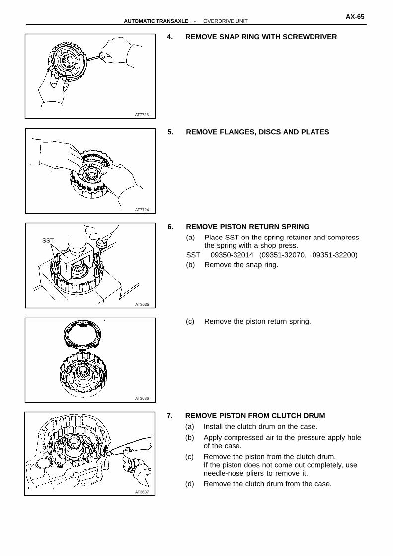
4. REMOVE SNAP RING WITH SCREWDRIVER
5. REMOVE FLANGES, DISCS AND PLATES
6. REMOVE PISTON RETURN SPRING(a) Place SST on the spring retainer and compress
the spring with a shop press.SST 09350-32014 (09351-32070, 09351-32200)(b) Remove the snap ring.
(c) Remove the piston return spring.
7. REMOVE PISTON FROM CLUTCH DRUM(a) Install the clutch drum on the case.
(b) Apply compressed air to the pressure apply holeof the case.
(c) Remove the piston from the clutch drum.If the piston does not come out completely, useneedle-nose pliers to remove it.
(d) Remove the clutch drum from the case.
-AUTOMATIC TRANSAXLE OVERDRIVE UNITAX-65
Z00365AT3639 AT3640
Q00362
PrintedNumbers
AT3641
AT3642
AT3638
OVERDRIVE DIRECT CLUTCH ASSEMBLY
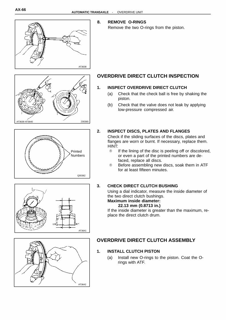
8. REMOVE O-RINGSRemove the two O-rings from the piston.
OVERDRIVE DIRECT CLUTCH INSPECTION
1. INSPECT OVERDRIVE DIRECT CLUTCH(a) Check that the check ball is free by shaking the
piston.
(b) Check that the valve does not leak by applyinglow-pressure compressed air.
2. INSPECT DISCS, PLATES AND FLANGESCheck if the sliding surfaces of the discs, plates andflanges are worn or burnt. If necessary, replace them.HINT:� If the lining of the disc is peeling off or discolored,
or even a part of the printed numbers are de-faced, replace all discs.
� Before assembling new discs, soak them in ATFfor at least fifteen minutes.
3. CHECK DIRECT CLUTCH BUSHINGUsing a dial indicator, measure the inside diameter ofthe two direct clutch bushings.Maximum inside diameter:
22.13 mm (0.8713 in.)If the inside diameter is greater than the maximum, re-place the direct clutch drum.
1. INSTALL CLUTCH PISTON(a) Install new O-rings to the piston. Coat the O-
rings with ATF.
AX-66-AUTOMATIC TRANSAXLE OVERDRIVE UNIT

AT7726
SST
AT7727
AT7725
AT3643
Plate Disc
Flange
AT3636
(b) Press the piston into the drum with the cup sideup, being careful not to damage the O-ring.
2. INSTALL PISTON RETURN SPRING(a) Install the return spring and seat snap ring in
place.
(b) Place SST on the spring retainer, and compressthe spring with a shop press.
SST 09350-32014 (09351-32070, 09351-32200)(c) Install the snap ring with a screwdriver. Be sure
end gap of snap ring is aligned with the groove ofthe clutch drum.
3. INSTALL PLATES, DISCS AND FLANGEInstall in order:P = Plate D = DiscP-D-P-D-Flange
4. INSTALL SNAP RINGBe sure end gap of the snap ring is not aligned with thegroove of the clutch drum.
-AUTOMATIC TRANSAXLE OVERDRIVE UNITAX-67

AT7721
AT3634
SST
AT3645
Hold
Lock
FreeTurn
AT2749
AT2748
5. INSTALL BEARING AND RACE(a) Coat the bearing with petroleum jelly and install it
facing the race side downward to the clutch drum.Bearing outer diameter:
46.3 mm (1.823 in.)Bearing inner diameter:
26.2 mm (1.031 in.)
(b) Coat the race with petroleum jelly and install it tothe case.
Race outer diameter:43.0 mm (1.693 in.)
Race inner diameter:24.5 mm (0.965 in.)
6. INSTALL DIRECT CLUTCH ON CASE
7. RECHECK PISTON STROKE OF DIRECT CLUTCHUsing a dial indicator, measure the piston stroke whileapplying and releasing the compressed air (392 - 785kPa, 4 - 8 kgf/cm2, 57 - 114 psi), as shown.Piston stroke:
1.75 - 2.49 mm (0.0689 - 0.0980 in.)SST 09350-32014 (09351-32190)
COUNTER DRIVE GEAR DISASSEMBLY
1. CHECK OPERATION OF ONE-WAY CLUTCH(a) Install the overdrive direct clutch into the one-
way clutch.
(b) Hold the overdrive direct clutch and turn the inter-mediate shaft. The shaft should turn freely clock-wise and should lock counterclockwise.
(c) Remove the overdrive direct clutch.
AX-68-AUTOMATIC TRANSAXLE OVERDRIVE UNIT

AT3751
AT3647
AT3648
O/D One-Way Clutch with Outer Race
RetainingPlate
AT3649
AT3646
2. CHECK COUNTER DRIVE GEAR PRELOAD(a) Hold the overdrive planetary gear in a vise with
soft jaws.HINT: Do not let the counter drive gear touch the vise.
(b) Using a tension gauge, measure the preload.Preload (at starting):
9.2 - 15.3 N (940 - 1,560 g, 2.1 - 3.4 lb)HINT: Turn the counter drive gear right and left severaltimes before measuring the preload.
3. REMOVE O/D ONE-WAY CLUTCH AND OUTERRACE(a) Remove the snap ring.
(b) Remove the retaining plate.
(c) Remove the O/D one-way clutch with outer race.
(d) Remove the two retainers from both sides of theO/D one-way clutch.
-AUTOMATIC TRANSAXLE OVERDRIVE UNITAX-69

AT5053
AT3650
AT3651
SST
AT3652
SST
AT0426
(e) Remove the O/D one-way clutch from the outerrace.
HINT: Note the direction of the one-way clutch.
4. REMOVE NO. 3 PLANETARY THRUST WASHER5. REMOVE PLUGS FROM PLANETARY GEAR
Remove the four plugs with a magnetic finger.HINT: Be careful not to lose them.
6. REMOVE ADJUSTING NUT AND LOCKING WASHER(a) Pry off the locking washer.
(b) Using SST, loosen the adjusting nut.SST 09350-32014 (09351-32080)(c) Remove the adjusting nut and locking washer.
7. REMOVE INTERMEDIATE SHAFT BEARINGUsing SST, press out the bearing from the shaft.SST 09950-00020
AX-70-AUTOMATIC TRANSAXLE OVERDRIVE UNIT

AT0431
SST
AT4431
AT3654
AT3655
AT3653
8. REMOVE COUNTER DRIVE GEAR AND FRONTBEARINGPress out the gear and bearing together.
9. REMOVE REAR BEARING(a) Using SST, press out the bearing.SST 09950-00020
(b) Tag the bearings to show the location for reas-sembly.
10. REMOVE OVERDRIVE PLANETARY RING GEARFROM COUNTER DRIVE GEAR(a) While pulling up the ring gear, compress the
snap ring with needle-nose pliers and remove itfrom the groove.
(b) Remove the ring gear from the counter drivegear.
(c) Remove the snap ring from the ring gear.
-AUTOMATIC TRANSAXLE OVERDRIVE UNITAX-71
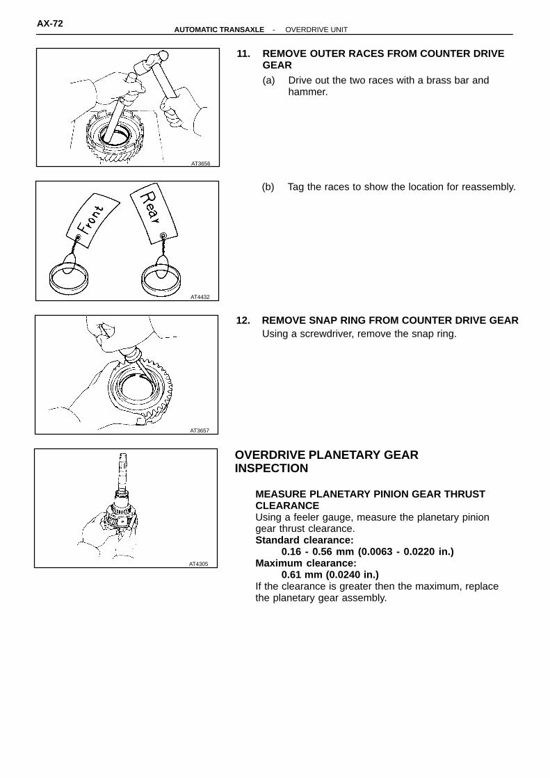
AT4432
AT3657
AT4305
AT3656
11. REMOVE OUTER RACES FROM COUNTER DRIVEGEAR(a) Drive out the two races with a brass bar and
hammer.
(b) Tag the races to show the location for reassembly.
12. REMOVE SNAP RING FROM COUNTER DRIVE GEARUsing a screwdriver, remove the snap ring.
OVERDRIVE PLANETARY GEAR INSPECTION
MEASURE PLANETARY PINION GEAR THRUSTCLEARANCEUsing a feeler gauge, measure the planetary piniongear thrust clearance.Standard clearance:
0.16 - 0.56 mm (0.0063 - 0.0220 in.)Maximum clearance:
0.61 mm (0.0240 in.)If the clearance is greater then the maximum, replacethe planetary gear assembly.
AX-72-AUTOMATIC TRANSAXLE OVERDRIVE UNIT

AT3658
A: FrontB: Rear
SST
AT3655
AT3659
AT3660
AT3657
COUNTER DRIVE GEAR ASSEMBLY
1. INSTALL SNAP RING INTO COUNTER GEARInstall the snap ring with a screwdriver.
2. INSTALL OUTER RACES INTO COUNTER DRIVEGEARUsing SST, press in the two outer races to both sidesof the gear.SST 09350-32014 (09351-32120, 09351-32150)HINT: Press in the two outer races until they touch thesnap ring. Tap the races in straight, so that they do nottilt.
3. INSTALL OVERDRIVE PLANETARY RING GEARINTO COUNTER DRIVE GEAR(a) Install the snap ring to the ring gear.
(b) While pushing down the ring gear, squeeze thesnap ring and with needle-nose pliers, and installit into the groove.
4. INSTALL REAR BEARINGUsing SST, press in the bearing onto the shaft.SST 09350-32014 (09351-32120)HINT: Press in the bearing until the side surface of theinner race touches the planetary carrier.
SST
-AUTOMATIC TRANSAXLE OVERDRIVE UNITAX-73

AT3663
SST
AT3665
Washer
AT3666
Adjusting Nut
AT3661
Counter DriveGear
Front Bearing
AT3662
SST
5. INSTALL COUNTER DRIVE GEAR AND FRONTBEARING(a) install the gear onto the shaft, and mesh the ring
gear with the planetary pinions.
(b) Place the front bearing on to the shaft.
(c) Using SST, press in the bearing until slightly playbetween the bearings.
SST 09350-32014 (09351-32120)HINT: Hold the ring gear to prevent it from falling.
6. INSTALL INTERMEDIATE SHAFT BEARINGUsing SST, press in the bearing until it slightly touchesthe front bearing of the counter drive gear.SST 09350-32014 (09351-32120)HINT: The counter drive gear can be turned lightly.
7. PLACE NEW LOCKING WASHER
8. INSTALL ADJUSTING NUT AND ADJUST PRELOADOF COUNTER DRIVE GEAR(a) Hold the overdrive planetary gear in a vise with
soft jaws.
(b) Using SST, tighten the adjusting nut until the following gear starting load is reached on thetension gauge.
SST 09350-32014 (09351-32080)Preload (at starting):
9.2 - 15.3 N (940 - 1,560 g, 2.1 - 3.4 lb)
AX-74-AUTOMATIC TRANSAXLE OVERDRIVE UNIT

AT5052
AT0426
AT3649
AT3748
AT3667
AdjustingNut
HINT: Turn the counter drive gear right and left severaltimes before measuring the preload.(c) Lock the adjusting nut with one tab on locking
washer. Bend the locking washer tab until it iseven with the adjusting nut groove.
9. INSTALL NO. 3 OVERDRIVE PLANETARY THRUSTWASHER
10. INSTALL PINION SHAFT PLUGSInstall the four plugs into the pinion shaft.
11. INSTALL OVERDRIVE ONE-WAY CLUTCH AND RETAINING PLATE(a) Install the one-way clutch into the outer race.
(b) Install the two retainer on both sides of the one-way clutch.
(c) Install the one-way clutch into the overdrive plan-etary gear.
HINT: Be sure that the one-way clutch is installed inthe correct direction.(d) Install the retaining plate.
-AUTOMATIC TRANSAXLE OVERDRIVE UNITAX-75

AT3668
AT3669
Piston
Plate
AT3670
AT3647
AT3645
Hold
Lock
FreeTurn
(e) Install the snap ring.
12. CHECK OPERATION OF O/D ONE-WAY CLUTCH(a) Install the overdrive direct clutch into the one-
way clutch.
(b) Hold the overdrive direct clutch and turn the inter-mediate shaft. The shaft should turn freely clock-wise and should lock counterclockwise.
(c) Remove the overdrive direct clutch.
OVERDRIVE CASE DISASSEMBLY
1. REMOVE C0 ACCUMULATOR PISTON FROM OVER-DRIVE CASE(a) Using snap ring pliers, remove the snap ring.
(b) Remove the retaining plate and two springs.
(c) Remove the accumulator piston.
(d) Remove the O-ring from the piston.
AX-76-AUTOMATIC TRANSAXLE OVERDRIVE UNIT

AT7728
AT3671
AT3669
Piston
Plate
AT3668
AT0441
2. REMOVE OIL SEAL RINGSSpread the two rings apart and remove them.
OVERDRIVE CASE ASSEMBLY
1. INSTALL OIL SEAL RINGS ON OVERDRIVE CASESpread the two rings apart and install them into thegroove.HINT: After installing the oil seal rings, check that theymove smoothly.
2. INSTALL C0 ACCUMULATOR PISTON TO OVER-DRIVE CASE(a) Install a new O-ring to the accumulator piston.
(b) Coat the O-ring with ATF.
(c) Install the accumulator piston, two springs andretaining plate.
(d) Using snap ring pliers, install the snap ring.
-AUTOMATIC TRANSAXLE OVERDRIVE UNITAX-77

AT7729
Drum
Piston
AT3672
Flange
DiscPlate
AT1905
AT2823
AT2756
OVERDRIVE BRAKE ASSEMBLY
1. INSTALL PISTON INTO DRUM(a) Install the new O-rings to the piston.
Coat the O-rings with ATF.
(b) Press the piston into the drum, being careful notto damage the O-rings.
2. INSTALL FLANGE, DISCS AND PLATES(a) Install the flange, discs and plates.
Install in order:P = Plate D = DiscFlange-D-P-D-P-D-P
(b) Install the cushion plate with the rounded endfacing upward.
3. POSITION PISTON RETURN SPRING
AX-78-AUTOMATIC TRANSAXLE OVERDRIVE UNIT
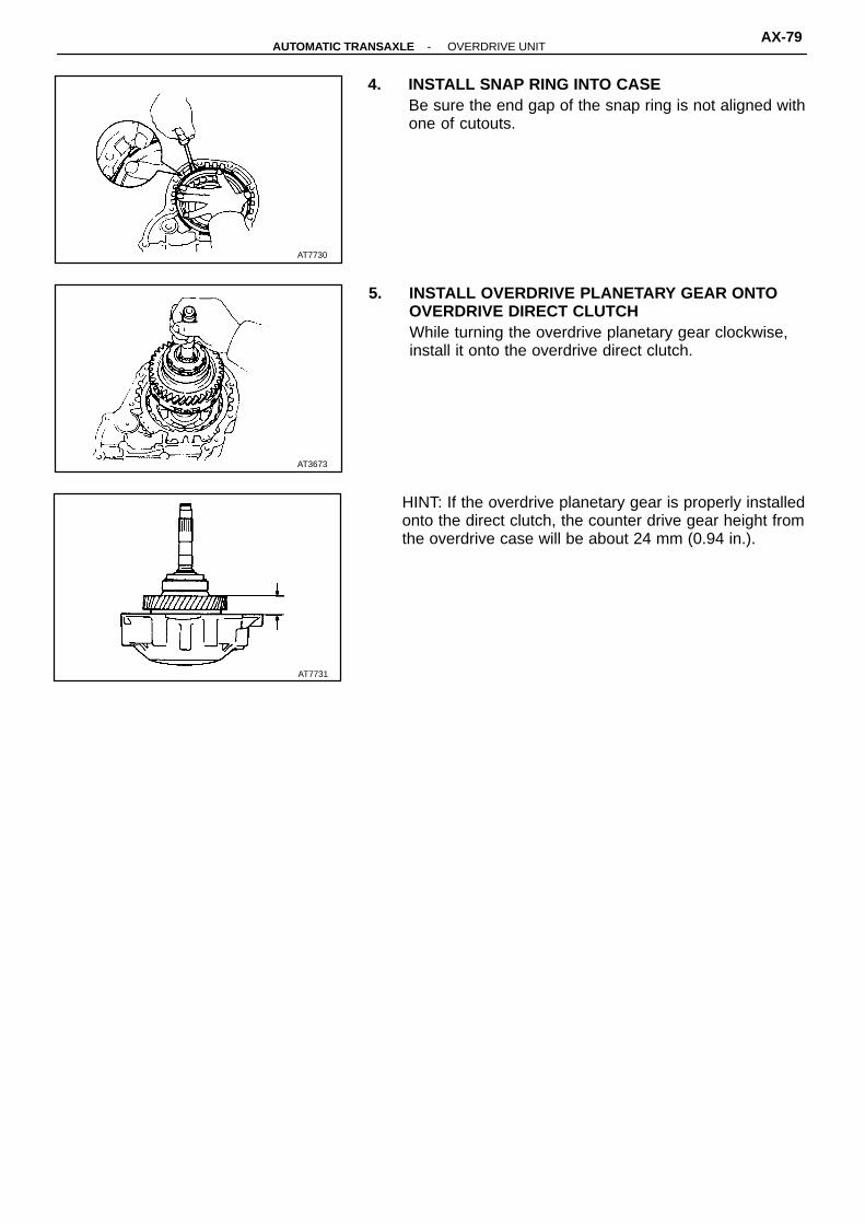
AT3673
AT7731
AT7730
4. INSTALL SNAP RING INTO CASEBe sure the end gap of the snap ring is not aligned withone of cutouts.
5. INSTALL OVERDRIVE PLANETARY GEAR ONTOOVERDRIVE DIRECT CLUTCHWhile turning the overdrive planetary gear clockwise,install it onto the overdrive direct clutch.
HINT: If the overdrive planetary gear is properly installedonto the direct clutch, the counter drive gear height fromthe overdrive case will be about 24 mm (0.94 in.).
-AUTOMATIC TRANSAXLE OVERDRIVE UNITAX-79

AT3462
No. 2 Solenoid
No. 1Solenoid
AT4500Lock-Up Solenoid
42 (1.65)
♦ Non-reusable part
N-m (kgf-cm, ft-lbf) 6.6 (67, 58 in.-lbf) AT3506
Check Ball
Piston
Lower Valve BodyCover
No. 2 plate♦ Gasket
♦ Gasket
Lower Valve Body
B0 AccumulatorCylinder
♦ O-RingCheck Ball
Sleeve Stopper
♦ No. 2 Gasket
Check Ball No. 1 Plate
♦ O-Ring ♦ No. 1 Gasket♦ Gasket
Upper Valve BodyCover
Oil Strainer6.6 (67, 58 in.-lbf) No. 1 and No. 2 Solenoids
Spring
♦ O-Ring
Specified torque
Upper Valve Body♦ Gasket
Plate
Lock-Up Solenoid
VALVE BODYCOMPONENTS
VALVE BODY DISASSEMBLY
NOTICE: When disassembling the valve body, becareful not to damage or deform the plate which over-hangs the valve body.
1. REMOVE SOLENOIDS
(a) Remove No. 1 and No. 2 solenoids.NOTICE: When removing the solenoid, do not use ascrewdriver, etc. to pry up the solenoid.(b) Remove the O-ring from each solenoid.
(c) Remove the lock-up solenoid.
(d) Remove the O-ring from the solenoid.
AX-80-AUTOMATIC TRANSAXLE VALVE BODY

AT3465
AT3468
GasketPlateGasket
Oil Strainer
AT3469
AT3467
Q00280
Check Ball
B0 Accumulator
2. REMOVE B0 ACCUMULATOR ASSEMBLY(a) Remove the two bolts.
(b) Remove the B0 accumulator assembly.
(c) Remove the check ball on No. 1 plate.
3. DISASSEMBLY B 0 ACCUMULATOR ASSEMBLY(a) Applying compressed air to the cylinder hole, re-
move the piston and spring.
(b) Remove the two O-ring from the piston.
4. REMOVE UPPER AND BODY COVERRemove the eleven bolts and upper and body cover.
5. REMOVE OIL STRAINER, UPPER VALVE BODYCOVER GASKETS AND PLATE(a) Remove the oil strainer on the gasket.
(b) Remove the two gaskets and plate from the up-per valve body.
6. REMOVE LOCK-UP RELAY VALE SLEEVE STOPPER
-AUTOMATIC TRANSAXLE VALVE BODYAX-81

AT3471
GasketPlateGasket
AT3472
AT3473
AT3474
AT3470
7. REMOVE LOWER VALVE BODY COVERRemove the twelve bolts and lower valve body cover.
8. REMOVE LOWER VALVE BODY COVER GASKETSAND NO. 2 PLATE
9. REMOVE CHECK BALLSRemove the two check balls from the lower valvebody.
10. REMOVE BOLT FROM LOWER VALVE BODY
11. REMOVE BOLTS FROM UPPER VALVE BODYRemove the three bolts.
AX-82-AUTOMATIC TRANSAXLE VALVE BODY

AT3489
No. 2GasketNo. 1 PlateNo. 1Gasket
Z00371AT3490 AT3491
No. 1 Gasket No. 2 Gasket
AT3475
AT3475
12. LIFT OFF UPPER VALVE BODY AND NO. 1 PLATEAS A SINGLE UNITHold No. 1 plate to the upper valve body and lift off theupper valve body.HINT: Be careful that the check balls and oil strainer donot fall out:
VALVE BODY ASSEMBLY
1. POSITION NO. 1 PLATE AND NEW GASKETS ONUPPER VALVE BODYPosition new No. 1 gasket, No. 1 plate and then newNo. 2 gasket on the upper valve body.HINT: Since No. 1 gasket and No. 2 gasket are similar,use the illustration below to discriminate betweenthem.
2. PLACE UPPER VALVE BODY WITH NO. 1 PLATEAND GASKETS ON LOWER VALVE BODYHold the upper valve body, No. 1 plate and gaskets securely so they do not separate.Align each bolt hole in the valve bodies with the gasketsand plate.
-AUTOMATIC TRANSAXLE VALVE BODYAX-83
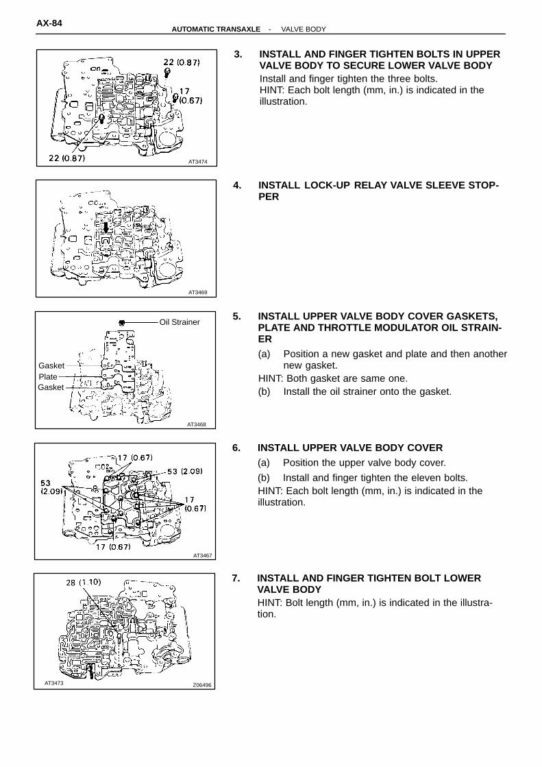
AT3468
GasketPlateGasket
Oil Strainer
AT3467
Z06496AT3473
AT3474
AT3469
3. INSTALL AND FINGER TIGHTEN BOLTS IN UPPERVALVE BODY TO SECURE LOWER VALVE BODYInstall and finger tighten the three bolts.HINT: Each bolt length (mm, in.) is indicated in the illustration.
4. INSTALL LOCK-UP RELAY VALVE SLEEVE STOP-PER
5. INSTALL UPPER VALVE BODY COVER GASKETS,PLATE AND THROTTLE MODULATOR OIL STRAIN-ER(a) Position a new gasket and plate and then another
new gasket.HINT: Both gasket are same one.(b) Install the oil strainer onto the gasket.
6. INSTALL UPPER VALVE BODY COVER(a) Position the upper valve body cover.
(b) Install and finger tighten the eleven bolts.HINT: Each bolt length (mm, in.) is indicated in theillustration.
7. INSTALL AND FINGER TIGHTEN BOLT LOWERVALVE BODYHINT: Bolt length (mm, in.) is indicated in the illustra-tion.
AX-84-AUTOMATIC TRANSAXLE VALVE BODY

AT3471
GasketPlateGasket
AT3470
AT3493
AT3492
AT3472
8. INSTALL CHECK BALLSInstall the two check balls into the lower valve body.
9. INSTALL LOWER VALVE BODY COVER GASKETSAND NO. 2 PLATEPosition a new gasket and plate and then another newgasket.HINT: Both gaskets are same one.
10. INSTALL LOWER VALVE BODY COVER(a) Position the lower valve body cover.
(b) Install and finger tighten the twelve bolts.HINT: Each bolt length (mm, in.) is indicated in theillustration.
11. TIGHTEN BOLTS OF UPPER AND LOWER VALVEBODIES(a) Tighten the thirteen bolts in the lower valve body.Torque: 6.6 N-m (67 kgf-cm, 58 in.-lbf)
(b) Tighten the fourteen bolts in the upper valvebody.
Torque: 6.6 N-m (67 kgf-cm, 58 in.-lbf)
-AUTOMATIC TRANSAXLE VALVE BODYAX-85

Q00387
AT4500Lock-Up Solenoid
Q00388
Free length
mm (in.)
Coil outer diameter
mm (in.)Color
67.7 (2.665) 14.0 (0.551) Pink
AT3466
Cylinder
Spring
Piston
O-Ring12. INSTALL B 0 ACCUMULATOR ASSEMBLY
(a) Coat new O-rings with ATF and install them tothe piston.
(b) Install the spring and piston into the cylinder.
(c) Plate the check ball on No. 1 gasket.
(d) Install the B0 accumulator assembly.
(e) Install the torque the two bolts.HINT: Each bolt length (mm, in.) is indicated in the il-lustration.Torque: 6.6 N-m (67 kgf-cm, 58 in.-lbf)
13. INSTALL SOLENOIDS(a) Coat new O-rings with ATF and install them to
the solenoids.
(b) Install the lock-up solenoid.
(c) Install and torque the bolt.HINT: Bolt length (mm, in.) is indicated in the illustra-tion.Torque: 6.6 N-m (67 kgf-cm, 58 in.-lbf)
(d) Install No. 1 and No. 2 solenoids.
(e) Install and torque the three bolts.HINT: Each bolt length (mm, in.) is indicated in theillustration.Torque: 6.6 N-m (67 kgf-cm, 58 in.-lbf)
AX-86-AUTOMATIC TRANSAXLE VALVE BODY

Z00370
AT3476AT3477
Lock-up Relay Valve
Plug
Lock-up RelayControl Valve
SleevePlugRetainer
No. 1 AccumulatorControl Valve
Plug
Plug Cut-back Valve
Retainer
Modulator ValveThrottle
Sleeve
Pin Down-shift Plug
Valve Vibrating Stopper
Oil Strainer
Retainer Throttle Valve
B1 OrificeControl Valve
Plate WasherPlug
Check BallPlug
Spring
Modulator Valve2nd Coast
The throttle pressure is changed according to the number of adjustingrings.When assembling the valve body,install the same number of adjustingrings as were removed.
Adjusting Ring
RetainerRetainer
Retainer
PinCam
Wave Washer
UPPER VALVE BODYCOMPONENTS
-AUTOMATIC TRANSAXLE UPPER VALVE BODYAX-87

Mark Name (Color)Free Length / Outer Diameter
mm (in.)Total No. of Coils
Second Coast Modulator Valve (Brown) 27.5 (1.083) / 8.9 (0.350) 14.6
B1 Orifice Control Valve (White) 24.8 (0.976) / 8.0 (0.315) 12.0
Down-Shift Plug (Yellow) 25.7 (1.012) / 6.7 (0.246) 9.65
Throttle Valve (Purple) 30.7 (1.209) / 9.2 (0.362) 9.5
Throttle Modulator Valve (Orange) 21.7 (0.854) / 9.5 (0.374) 9.5
Cut-Back Valve (Red) 21.8 (0.858) / 6.0 (0.236) 13.5
(Yellow)
No. 1 Accumulator Control Valve28.1 (1.106) / 10.6 (0.417) 13.0
Lock-Up Relay Valve (Green) 26.6 (1.047) / 10.2 (0.402) 11.5
AT3603
Sectional View
VALVE BODY SPRINGS SPECIFICATIONS
HINT: During reassembly please refer to the spring specifications above to help discriminate thedifferent springs.
AX-88-AUTOMATIC TRANSAXLE UPPER VALVE BODY

Mark Namemm (in.)
Height / Width / Thickness
Primary Regulator Valve 9.2 (0.362) / 5.0 (0.197) / 3.2 (0.126)
Secondary Regulator Valve 15.0 (0.591) / 5.0 (0.197) / 3.2 (0.126)
No. 2 Accumulator Control Valve 9.2 (0.362) / 5.0 (0.197) / 3.2 (0.126)
Second Lock Valve 11.5 (0.453) / 5.0 (0.197) / 3.2 (0.126)
Low Coast Modulator Valve 11.5 (0.453) / 5.0 (0.197) / 3.2 (0.126)
1 - 2 Shift Valve 6.5 (0.256) / 5.0 (0.197) / 3.2 (0.126)
2 - 3 Shift Valve 9.2 (0.362) / 5.0 (0.197) / 3.2 (0.126)
3 - 4 Shift Valve 6.5 (0.256) / 5.0 (0.197) / 3.2 (0.126)
AT3485AT3484
(Upper Side) (Lower Side)
RETAINERS, PIN, STOPPER, CHECK BALL AND STRAINER LOCATION
1. RETAINER
V02459
-AUTOMATIC TRANSAXLE UPPER VALVE BODYAX-89

AT4501 AT3487
3. STRAINER2. CHECK BALL
V02460
AX-90-AUTOMATIC TRANSAXLE UPPER VALVE BODY

Z00369
AT4502AT3483
The line pressure changes according to the part of the plunger sleeve which comes into contact with the retainer.When reassembling the valve body, position the retainer in the same position.Plunger Sleeve
Retainer
Plug
PlungerRetainerRetainer
Shift Valve PlugPlug
Primary RegulatorValve
Plate Washer
Retainer
1 - 2 Shift Valve
Low Coast Modulator Valve
Retainer
Plug3 - 4 Shift Valve
Plug
RetainerPlug
RetainerPlug
No. 2 AccumulatorControl ValveRetainer
Check Ball
Secondary Regulator Valve
Oil StrainerCheck Valve
Pressure Relief Valve Check Ball
2nd lock Valve
2 - 3 Shift Valve
LOWER VALVE BODYCOMPONENTS
-AUTOMATIC TRANSAXLE LOWER VALVE BODYAX-91

Mark Name (Color)Free Length / Outer Diameter
mm (in.)Total No. of Coils
Pressure Relief Valve (None) 11.2 (0.441) / 6.4 (0.252) 7.5
Check Valve (None) 19.9 (0.783) / 11.0 (0.433) 8.5
Secondary Regulator Valve (Purple) 38.5 (1.516) / 8.4 (0.331) 17.0
No. 2 Accumulator Control Valve (Gray) 23.0 (0.906) / 6.3 (0.248) 12.0
Second Lock Valve (Orange) 20.7 (0.815) / 6.1 (0.240) 12.0
3 - 4 Shift Valve (Light Green) 29.2 (1.150) / 8.9 (0.350) 12.0
Low Coast Modulator Valve (Purple) 20.2 (0.975) / 7.9 (0.311) 11.9
1 - 2 Shift Valve (None) 33.5 (1.319) / 8.9 (0.350) 12.0
2 - 3 Shift Valve (None) 28.0 (1.102) / 9.4 (0.370) 10.3
Primary Regulator Valve (None) 64.2 (2.528) / 18.6 (0.732) 12.5
Z05469
Q00386
VALVE BODY SPRINGS SPECIFICATIONS
HINT: During reassembly please refer to the spring specifications above to help discriminate thedifferent springs.
AX-92-AUTOMATIC TRANSAXLE LOWER VALVE BODY

AT3480 AT3481
Mark Name Height / Width / Thickness mm (in.)
Lock-Up Relay Valve 6.5 (0.256) / 5.0 (0.197) / 3.2 (0.126)
Throttle Modulator Valve 6.5 (0.256) / 5.0 (0.197) / 3.2 (0.126)
Second Coast Modulator Valve 6.5 (0.256) / 5.0 (0.197) / 3.2 (0.126)
Cut-Back Valve 9.2 (0.362) / 5.0 (0.197) / 3.2 (0.126)
No. 1 Accumulator Control Valve 6.5 (0.256) / 5.0 (0.197) / 3.2 (0.126)
B1 Orifice Control Valve 11.5 (0.453) / 5.0 (0.197) / 3.2 (0.126)
AT3478AT3479
Pin
ValveVibratingStopper
(Lower Side)(Upper Side)
RETAINERS, CHECK BALLS AND STRAINERS LOCATION
1. RETAINER, STOPPER AND PIN
V02463
2. CHECK BALL 3. STRAINER
V02464
-AUTOMATIC TRANSAXLE LOWER VALVE BODYAX-93

♦ Non-reusable part� Precoated part
Q00377
N-m (kgf-cm, ft-lbf) : Specified torque
♦ Oil Seal
124 (1,260, 91)Oil BaffleDifferential PinionLH Side Bearing Retainer
Adjusting Shim
Outer Race
SideBearing
Side GearThrust Washer
Ring GearDifferential Left Case
SpeedometerDrive Gear
Differential Right Case
Side Bearing
Outer Race♦ Lock Nut
Shim
63 (640, 46)
RH RetainerCounter Driven Gear
♦ Oil Seal♦ Bearing
19 (195, 14)�
Oil Slinger
Sensor Rotor
Snap Ring
♦ Oil Seal
BearingCage
Outer Race
BearingDrive Pinion
Pinion Thrust Washer
DifferentialSpider
DifferentialSide Gear
♦ Spacer
Outer Race
DIFFERENTIAL ASSEMBLYCOMPONENTS
AX-94-AUTOMATIC TRANSAXLE DIFFERENTIAL ASSEMBLY
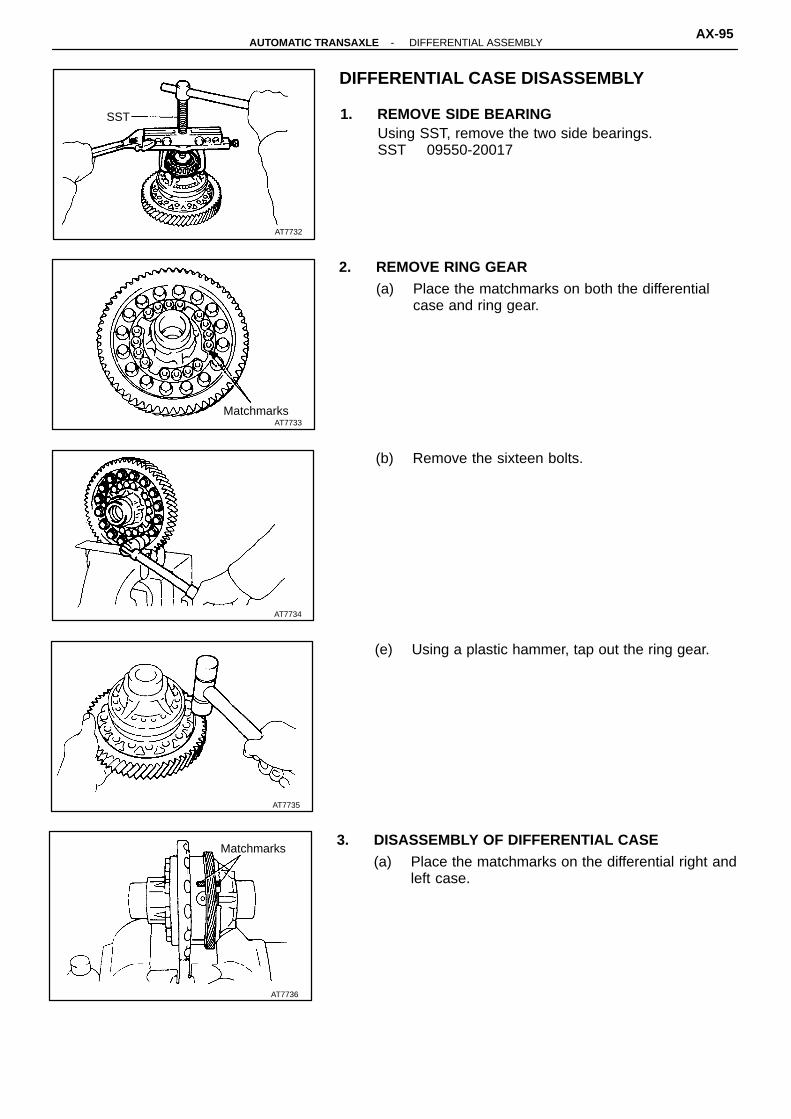
AT7734
AT7735
AT7736
Matchmarks
MatchmarksAT7733
AT7732
SST
DIFFERENTIAL CASE DISASSEMBLY
1. REMOVE SIDE BEARINGUsing SST, remove the two side bearings.SST 09550-20017
2. REMOVE RING GEAR(a) Place the matchmarks on both the differential
case and ring gear.
(b) Remove the sixteen bolts.
(e) Using a plastic hammer, tap out the ring gear.
3. DISASSEMBLY OF DIFFERENTIAL CASE(a) Place the matchmarks on the differential right and
left case.
-AUTOMATIC TRANSAXLE DIFFERENTIAL ASSEMBLYAX-95

AT7739
AT3675
AT3676
AT7737
AT7738
(b) Using a torx wrench, remove the sixteen torxscrews.
(c) Using a plastic hammer, tap out the differentialleft case.
(d) Remove the speedometer drive gear from thedifferential right case.
(e) Remove the two differential side gears, two sidethrust washers, differential spider, four differentialpinions and four pinion washers from the differ-ential left case.
4. DISASSEMBLY LH BEARING RETAINER(a) Using a hammer and screwdriver, remove the oil
seal.
(b) Remove the oil baffle from the LH bearing retainer.
(c) Using a hammer and brass bar, drive out the outerrace and adjusting shim from LH bearing retainer.
AX-96-AUTOMATIC TRANSAXLE DIFFERENTIAL ASSEMBLY

AT3678
SST
AT3679
AT3680
SST
AT7740
AT3677
5. REMOVE RH OIL SEAL FROM RH RETAINERUsing a hammer and screwdriver, drive out the oil seal.
DIFFERENTIAL CASE ASSEMBLY
1. INSTALL RH OIL SEAL TO RH RETAINER(a) Using SST, drive in a new oil seal until its surface
is flush with the surface of RH retainer.SST 09316-60010 (09316-00010)(b) Coat the oil seal lip with MP grease.
2. INSTALL ADJUSTING SHIM AND BEARING OUTERRACE TO LH BEARING RETAINER(a) Place the adjusting shim into the LH bearing
retainer.HINT: Use either the shim which was removed or one2.40 mm (0.0945 in.).
(b) Using SST, press the outer race into the LH retainer.
SST 09316-2001 1, 09350-32014 (09351-32150)HINT: Install the oil baffle and oil seal after adjustingthe differential side bearing preload.(See page AX-106 )
3. ASSEMBLE DIFFERENTIAL CASEHINT: Coat all of the sliding and rotating surface withATF before assembly.(a) Install the thrust washer to the side gear.
-AUTOMATIC TRANSAXLE DIFFERENTIAL ASSEMBLYAX-97

AT7743
AT7744
Matchmarks
AT7741
Thickness mm (in.) Thickness mm (in.)
0.80 (0.0315) 1.20 (0.0472)
0.90 (0.0354) 1.30 (0.0512)
1.00 (0.0394) 1.40 (0.0551)
1.10 (0.0433)
AT7742
(b) Install the four pinions and thrust washers to thespider.
(c) Install the side gear and spider with four pinionsto the differential left case.
(d) Using a dial indicator, measure the backlash ofone pinion gear while holding the side gear.
Standard backlash:0.05 - 0.20 mm (0.0020 - 0.0079 in.)
(e) Install the side gear and spider with four pinionsto the right side of the differential case. Andcheck the pinion gear backlash.
(f) Referring to the table below, select the side gearthrust washer which will ensure that the backlashis within specification. Try to select a washer ofthe same size.
(g) Install the speedometer drive gear.
(h) Align the matchmarks on the differential cases.
AX-98-AUTOMATIC TRANSAXLE DIFFERENTIAL ASSEMBLY

AT7748
SpeedometerDriven GearSide
AT3681
SST
AT7746
AT7747
AT7745
(l) Using a plastic hammer, carefully tap the differentialright case.
(j) Using a torx wrench, install and torque the six-teen torx screws.
Torque: 63 N-m (640 kgf-cm, 46 ft-lbf)
4. INSTALL RING GEAR(a) Clean the contact surface of the differential case.
(b) Heat the ring gear to about 100°C (212°F) in anoil bath.
NOTICE: Do not heat the ring gear above 110 °C(230°F).(c) Clean the contact surface of the ring gear with
cleaning solvent.
(d) Quickly install the ring gear on the differentialcase. Install the sixteen bolts.
HINT: Align the matchmarks on the differential left caseand contact the ring gear.(e) Tighten the set bolts uniformly and a little at a
time. Torque the bolts.Torque: 124 N-m (1,260 kgf-cm, 91 ft-lbf)
5. INSTALL SIDE BEARINGS(a) Using SST and a press, install the RH side bearing
to the differential case.SST 09361-2001 1
-AUTOMATIC TRANSAXLE DIFFERENTIAL ASSEMBLYAX-99

AT3682
SST
(b) Using SST and a press, install the LH side bearing.SST 09316-60010 (09316-00010)
AX-100-AUTOMATIC TRANSAXLE DIFFERENTIAL ASSEMBLY

COMPONENT PARTS INSTALLATIONDisassembly, inspection and assembly of each component group have been indicated in the preceding chapter. Before assembly, make sure, again, that all component groups are assembled correctly.If something wrong is found in a certain component group during assembly, inspect and repairthis group immediately.Recommended ATF:
DEXRON� II
GENERAL INSTALLATION NOTES:
(a) The automatic transaxle is composed of highly precision-finished parts, necessitating careful inspec-tion before assembly because even a small nick could cause fluid leakage or affect performance.
(b) Before assembling new clutch discs, soak them in automatic transaxle fluid for at least fifteen minutes.
(c) Apply automatic transaxle fluid on the, sliding or rotating surfaces of parts before assembly.
(d) Use petroleum jelly to keep small parts in their places.
(e) Do not use adhesive cements on gaskets and similar parts.
(f) When assembling the transaxle, be sure to use new gaskets and O-rings.
(g) Dry all parts with compressed air - never use shop rags.
(h) Be sure to install the thrust bearings and races in the correct direction and position.
-AUTOMATIC TRANSAXLE COMPONENT PARTS INSTALLATIONAX-101

MarkThrust Bearing Outside Diameter
mm (in.)
Thrust Bearing Inside Diameter
mm (in.)
A See page AX-118 27.7 (1.091)
B 47.6 (1.874) 31.4 (1.236)
C 45.5 (1.791) 30.1 (1.185)
D 45.5 (1.791) 30.1 (1.185)
E 38.7 (1.524) 22.6 (0.890)
F 46.3 (1.823) 28.6 (1.126)
AT3690
AX-102-AUTOMATIC TRANSAXLE COMPONENT PARTS INSTALLATION

AT3692
AT3595
SST
AT3594
AT3593
Oil Slinger
Spacer
Q00265
DIFFERENTIAL AND DRIVE PINIONINSTALLATION
1. INSTALL DRIVE PINION INTO TRANSAXLE CASE(a) Place the bearing cage onto the drive pinion
shaft.NOTICE: Be careful not to damage the oil seals withthe pinion shaft.
(b) Using a hammer and brass bar, slightly tap thebearing cage into the transaxle case until thesnap ring groove in the bore can be seen.
(a) Using SST, install snap ring into the bore.SST 09350-32014 (09351-32050)
2. PLACE SENSOR ROTOR ONTO DRIVE PINIONSHAFT
3. PLACE OIL SLINGER AND NEW SPACERHINT: Install the spacer with the small end downward.
-AUTOMATIC TRANSAXLE COMPONENT PARTS INSTALLATIONAX-103

AT3695
SST
AT3693
Outer Race
SST
SST
AT3588
AT3694
SST (a)
CounterDrive Gear SST (b)
4. INSTALL OUTER RACE TO TRANSAXLE CASEUsing SST, press in the outer race.SST 09350-32014 (09351-32100, 09351-32140)
5. INSTALL COUNTER DRIVE GEAR(a) Place SST into the transaxle hole to hold the
drive pinion shaft.SST 09350-32014 (09351-32130, 09351-32150)(a) Using SST, press in the counter driven gear until
slightly thickness between the counter drivengear bearing and outer race.
SST 09350-32014 (09351-32140)
6. INSTALL NEW LOCK NUT AND ADJUST DRIVE PINION PRELOAD(a) Install the new lock nut.
(b) Using SST to hold the gear, tighten the nut.Torque: 206 N-m (2,100 kgf-cm, 152 ft-lbf)SST 09330-00021, 09350-32014 (09351-32032)(c) Turn the gear counterclockwise and clockwise
several times.
(d) Using a torque meter, measure the preload of thedrive pinion.
Drive pinion preload (at starting):New bearing
1.0 - 1.6 N-m (10 - 16 kgf-cm, 8.7 - 13.9 in.-lbf)Reused bearing
0.5 - 0.8 N-m (5 - 8 kgf-cm, 4.3 - 6.9 in.-lbf)� If the preload is greater than specified, replace
the bearing spacer.� If the preload is less then specified, retighten
the nut 13 N-m (130 kgf-cm, 9 ft-lbf) at a timeuntil the specified preload is reached.
If the maximum torque is exceeded while retighteningthe nut, replace the bearing spacer and repeat the pre-load procedure.Do not back off the nut to reduce the preload.Maximum torque: 353 N-m (3,600 kgf-cm, 260 ft-lbf)
AX-104-AUTOMATIC TRANSAXLE COMPONENT PARTS INSTALLATION
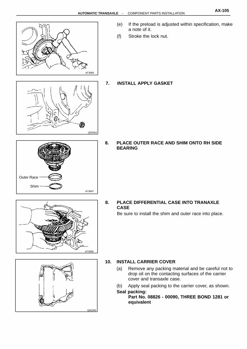
Q00264
Q00290
AT3697
Shim
Outer Race
AT3585
AT3969
(e) If the preload is adjusted within specification, makea note of it.
(f) Stroke the lock nut.
7. INSTALL APPLY GASKET
8. PLACE OUTER RACE AND SHIM ONTO RH SIDEBEARING
8. PLACE DIFFERENTIAL CASE INTO TRANAXLECASEBe sure to install the shim and outer race into place.
10. INSTALL CARRIER COVER(a) Remove any packing material and be careful not to
drop oil on the contacting surfaces of the carriercover and transaxle case.
(b) Apply seal packing to the carrier cover, as shown.Seal packing:
Part No. 08826 - 00090, THREE BOND 1281 orequivalent
-AUTOMATIC TRANSAXLE COMPONENT PARTS INSTALLATIONAX-105

AT4171
Q00282
AT4170
HINT: Install the carrier cover within ten minutes afterapplying seal packing.
(c) Install and torque the eleven bolts.Torque: 39 N-m (400 kgf-cm, 29 ft-lbf)HINT: Each bolt length (mm, in.) is indicated in theillustration.
11. ADJUST SIDE BEARING PRELOAD(a) Remove any packing material on the contacting
surfaces of the LH bearing retainer and transaxlecase.
HINT: Do not apply seal packing yet.(b) Install the LH bearing retainer and torque the six
bolts.Torque: 19 N-m (195 kgf-cm, 14 ft-lbf)(c) Snap down the bearings by turning the differential
case several times.
(d) Using a torque meter, measure the differential totalpreload.
Total preload (at starting):Add drive pinion preloadNew bearing
0.2 - 0.4 N-m (2.5 - 5.1 kgf-cm, 2.2 - 3.6 in.-lbf)Reused bearing
0.1 - 0.2 N-m (1.3 - 2.0 kgf-cm, 1.1 - 1.7 in.-lbf)If the preload is not within specification, replace the ad-justing shim in the LH bearing retainer with anotherthickness one.
AX-106-AUTOMATIC TRANSAXLE COMPONENT PARTS INSTALLATION

AT4170
AT4170
Mark Thickness mm (in.) Mark Thickness mm (in.)
0 2.00 (0.0787) 9 2.45 (0.0965)
1 2.05 (0.0807) A 2.50 (0.0984)
2 2.10 (0.0827) B 2.55 (0.1004)
3 2.15 (0.0846) C 2.60 (0.1024)
4 2.20 (0.0866) D 2.65 (0.1043)
5 2.25 (0.0886) E 2.70 (0.1063)
6 2.30 (0.0906) F 2.75 (0.1083)
7 2.35 (0.0925) G 2.80 (0.1102)
8 2.40 (0.0945) H 2.85 (0.1122)
AT4563
AT3700
Adjusting Shim
Adjusting shim thickness:
12. INSTALL LH BEARING RETAINER(a) Remove the six bolts and LH bearing retainer.
(b) Remove any packing material on the contactingsurfaces of LH bearing retainer, transaxle caseand carrier cover.
(c) Apply the seal packing to the transaxle case andcarrier cover, as shown.
Seal packing:Part No. 08826 - 00090, THREE BOND 1281 orequivalent
HINT: Install the LH bearing retainer with ten minutesafter applying seal packing.(d) Install the LH bearing retainer.
(e) Coat the threads of bolts with sealer.Sealer:
Part No. 08833 - 00070, THREE BOND 1324 orequivalent
(f) Tighten the bolts.Torque: 19 N-m (195 kgf-cm, 14 ft-lbf)(g) Snap down the bearings.
(h) Recheck the differential total preload.
-AUTOMATIC TRANSAXLE COMPONENT PARTS INSTALLATIONAX-107
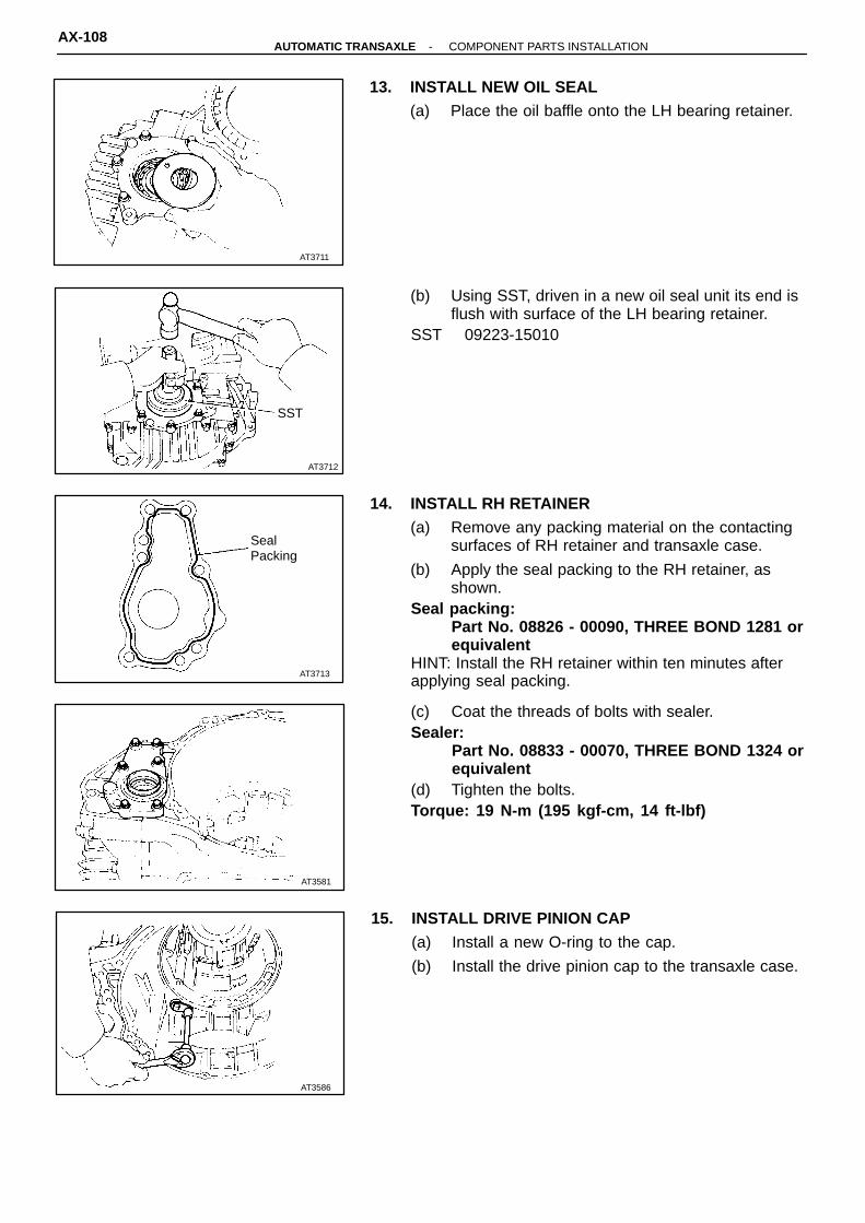
AT3712
SST
AT3713
SealPacking
AT3581
AT3586
AT3711
13. INSTALL NEW OIL SEAL(a) Place the oil baffle onto the LH bearing retainer.
(b) Using SST, driven in a new oil seal unit its end isflush with surface of the LH bearing retainer.
SST 09223-15010
14. INSTALL RH RETAINER(a) Remove any packing material on the contacting
surfaces of RH retainer and transaxle case.
(b) Apply the seal packing to the RH retainer, asshown.
Seal packing:Part No. 08826 - 00090, THREE BOND 1281 orequivalent
HINT: Install the RH retainer within ten minutes afterapplying seal packing.
(c) Coat the threads of bolts with sealer.Sealer:
Part No. 08833 - 00070, THREE BOND 1324 orequivalent
(d) Tighten the bolts.Torque: 19 N-m (195 kgf-cm, 14 ft-lbf)
15. INSTALL DRIVE PINION CAP(a) Install a new O-ring to the cap.
(b) Install the drive pinion cap to the transaxle case.
AX-108-AUTOMATIC TRANSAXLE COMPONENT PARTS INSTALLATION

AT7759
AT0090
ManualValve Lever
ParkingLock Rod
AT3576
AT3574
AT2731Lock Pawl
Pin 4-SPEED GEAR UNIT INSTALLATION
1. INSTALL PARKING LOCK PAWL(a) Place the parking lock pawl onto the case.
Hook the spring ends to the case and pawl.
(b) Instal the pin into the hole of the case through thespring and pawl.
2. INSTALL MANUAL VALVE SHAFT(a) Coat the oil seal lip with the MP grease.
(b) Install the manual valve shaft oil seal to the case.
(c) Assembly a new collar to the manual valve lever.
(d) Install the manual valve shaft to the transmissioncase through the manual lever.
(e) Install the parking lock rod.
(f) Using a pin punch, drive in the roll pin until its sur-face is flush with the manual valve lever surface.
-AUTOMATIC TRANSAXLE COMPONENT PARTS INSTALLATIONAX-109
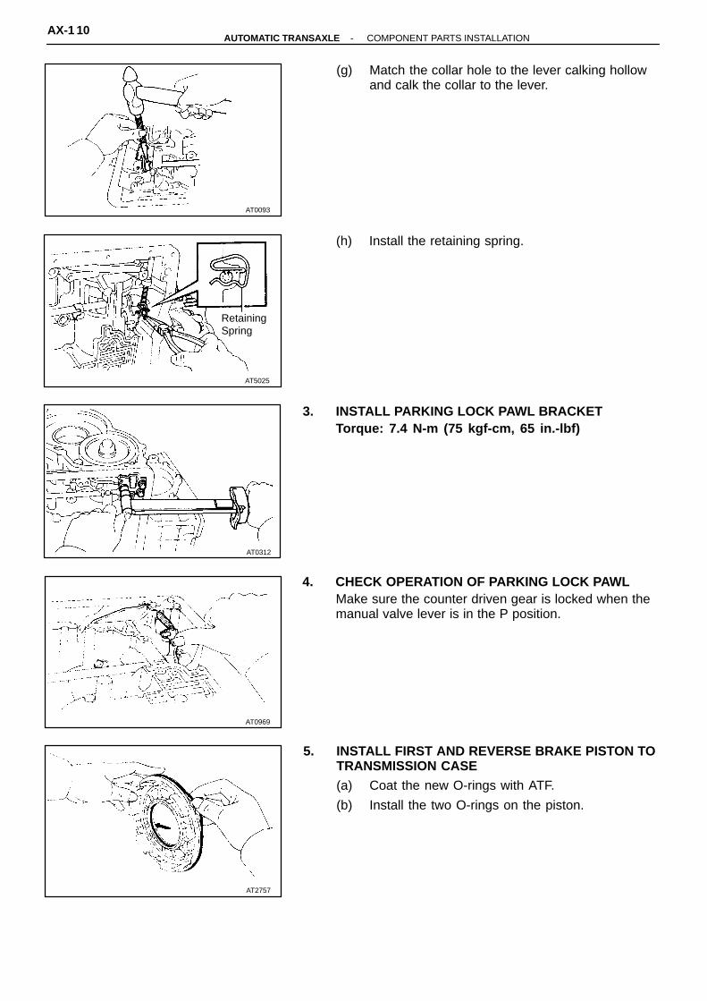
AT0312
AT0969
AT2757
AT0093
AT5025
RetainingSpring
(g) Match the collar hole to the lever calking hollowand calk the collar to the lever.
(h) Install the retaining spring.
3. INSTALL PARKING LOCK PAWL BRACKETTorque: 7.4 N-m (75 kgf-cm, 65 in.-lbf)
4. CHECK OPERATION OF PARKING LOCK PAWLMake sure the counter driven gear is locked when themanual valve lever is in the P position.
5. INSTALL FIRST AND REVERSE BRAKE PISTON TOTRANSMISSION CASE(a) Coat the new O-rings with ATF.
(b) Install the two O-rings on the piston.
AX-1 10-AUTOMATIC TRANSAXLE COMPONENT PARTS INSTALLATION
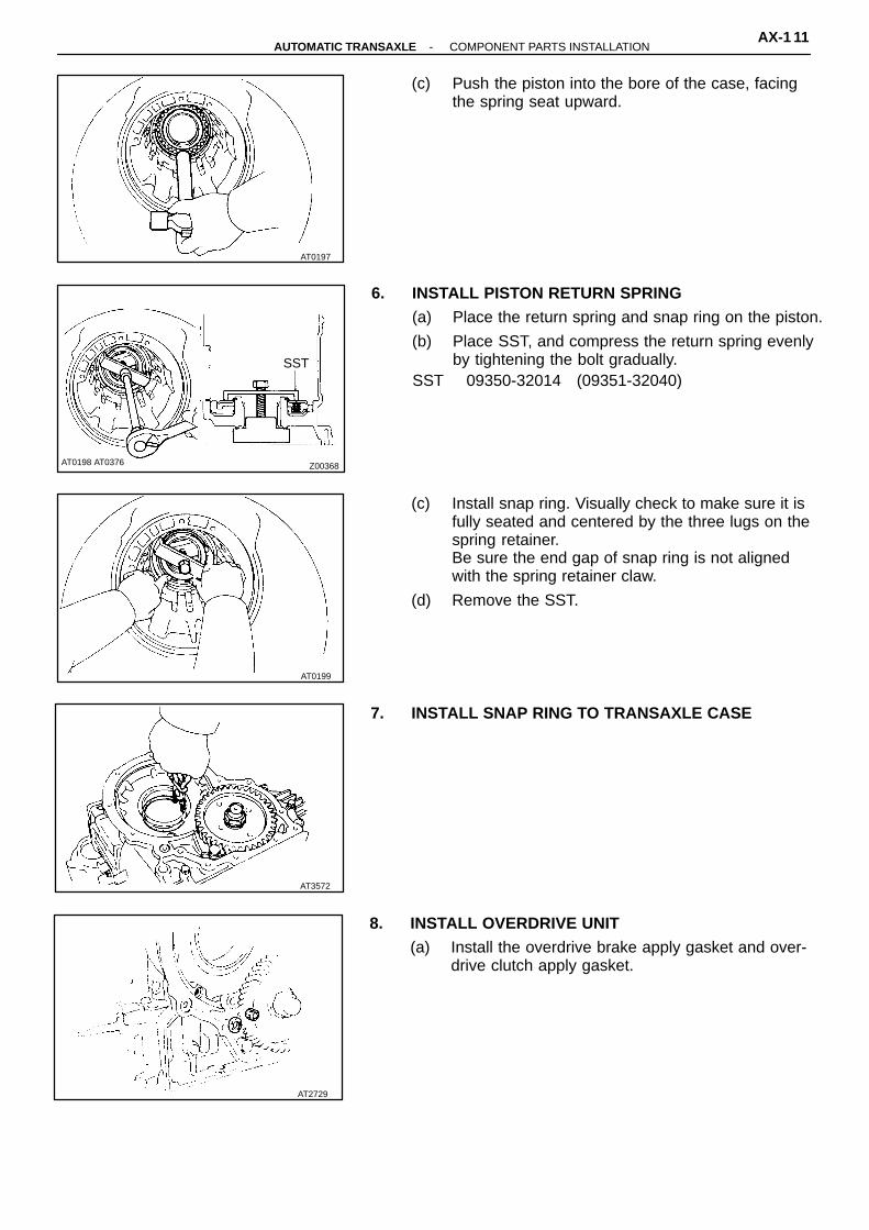
AT0199
AT3572
AT2729
AT0197
Z00368AT0198 AT0376
SST
(c) Push the piston into the bore of the case, facingthe spring seat upward.
6. INSTALL PISTON RETURN SPRING(a) Place the return spring and snap ring on the piston.
(b) Place SST, and compress the return spring evenlyby tightening the bolt gradually.
SST 09350-32014 (09351-32040)
(c) Install snap ring. Visually check to make sure it isfully seated and centered by the three lugs on thespring retainer.Be sure the end gap of snap ring is not alignedwith the spring retainer claw.
(d) Remove the SST.
7. INSTALL SNAP RING TO TRANSAXLE CASE
8. INSTALL OVERDRIVE UNIT(a) Install the overdrive brake apply gasket and over-
drive clutch apply gasket.
-AUTOMATIC TRANSAXLE COMPONENT PARTS INSTALLATIONAX-1 11
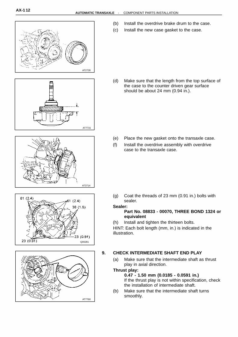
AT7731
AT3714
Q00281
AT7760
AT2728
(b) Install the overdrive brake drum to the case.
(c) Install the new case gasket to the case.
(d) Make sure that the length from the top surface ofthe case to the counter driven gear surfaceshould be about 24 mm (0.94 in.).
(e) Place the new gasket onto the transaxle case.
(f) Install the overdrive assembly with overdrivecase to the transaxle case.
(g) Coat the threads of 23 mm (0.91 in.) bolts withsealer.
Sealer:Part No. 08833 - 00070, THREE BOND 1324 orequivalent
(h) Install and tighten the thirteen bolts.HINT: Each bolt length (mm, in.) is indicated in the illustration.
9. CHECK INTERMEDIATE SHAFT END PLAY(a) Make sure that the intermediate shaft as thrust
play in axial direction.Thrust play:
0.47 - 1.50 mm (0.0185 - 0.0591 in.)If the thrust play is not within specification, checkthe installation of intermediate shaft.
(b) Make sure that the intermediate shaft turnssmoothly.
AX-1 12-AUTOMATIC TRANSAXLE COMPONENT PARTS INSTALLATION

Q00266
Q00267
AT3718
Disc Plate
Flange
Q00268
AT3715
10. INSTALL REAR PLANETARY GEAR(a) Install the rear planetary ring gear.
(b) Place the bearing onto the ring gear.Bearing outer diameter:
38.7 mm (1.524 in.)Bearing inner diameter:
22.6 mm (0.890 in.)
(c) Coat the thrust washer with petroleum jelly andplace it onto the rear planetary gear.
(d) Install the rear planetary gear.
11. INSTALL DISCS, PLATES AND FLANGE OF FIRSTAND REVERSE BRAKE(a) Install the seven plates and seven discs.
Install in order:P = Plate D = DiscP-D-P-D-P-D-P-D-P-D-P-D-P-D
(b) Install the flange, facing the flat end downward.
(c) Install the snap ring.HINT: Be sure that the end gap of the snap ring is notaligned with one of cutouts.
-AUTOMATIC TRANSAXLE COMPONENT PARTS INSTALLATIONAX-1 13

AT3602
AT3720
Q00276
SST
Q00273
AT3563
12. CHECK FIRST AND REVERSE BRAKE(a) Check the operation of the first and reverse
brake piston.Apply compressed air into the case passage and con-firm that the piston moves.
(b) Using a filler gauge, check that pack clearance ofthe first and reverse brake.
Clearance:0.85 - 2.05 mm (0.033 - 0.081 in.)
13. INSTALL NO. 2 ONE-WAY CLUTCH INTO CASE(a) Place the No. 2 one-way clutch with the shiny side
of flange upward.
(b) Install the one-way clutch while turning the plan-etary gear clockwise with SST.
SST 09350-32014 (09351-32050)If can not turn the planetary gear clockwise, check theinstallation of the one-way clutch.
(c) Install the snap ring.HINT: Be sure that the end gap of the snap ring is notaligned with one of cutouts.(d) Coat the thrust washer with petroleum jelly and
install it onto the rear planetary gear.
AX-1 14-AUTOMATIC TRANSAXLE COMPONENT PARTS INSTALLATION

AT3724
AT3556
AT3725
AT3726
Flange
PlateDisc
AT3723
14. INSTALL SECOND COAST BRAKE BAND GUIDE
15. PLACE NO. 1 ONE-WAY CLUTCH(a) Coat the thrust washer with petroleum jelly and
install it on the No. 1 one-way clutch.
(b) Place the No. 1 one-way clutch onto the rearplanetary gear.
16. INSTALL SECOND BRAKE(a) Install the flange, facing the flat end upward.
(b) Install the three discs and plates.Install in order:P = Plate D = DiscD-P-D-P-D-P
(c) Place the piston return spring into the case.
-AUTOMATIC TRANSAXLE COMPONENT PARTS INSTALLATIONAX-1 15

AT0335
AT7761
AT3601
AT3727
AT0334
(d) Place the second brake drum into the case.HINT: Align the groove of the drum with the bolt.
(e) Place the snap ring into the case so that end gapis installed into the groove.
(f) While compressing the piston return spring overthe drum with hammer handles, install the snapring into the groove.
(g) Be sure that the end gap of the snap ring is notaligned with one of cutouts.
17. INSTALL NEW SECOND BRAKE GASKETInstall a new gasket until it makes contact with the second brake drum.
18. CHECK OPERATION OF SECOND BRAKEApply compressed air into the second brake gasketand confirm that the piston moves.
19. INSTALL SUN GEAR AND SUN GEAR INPUT DRUM(a) Coat the thrust washer with petroleum jelly and
install it on the sun gear input drum.
AX-1 16-AUTOMATIC TRANSAXLE COMPONENT PARTS INSTALLATION

AT3730
AT3729
AT3551
AT3550
AT3728
(b) While turning the sun gear clockwise, install it intothe No. 1 one-way clutch.
20. INSTALL OIL SEAL RING TO INTERMEDIATESHAFTHINT: After installing the oil seal ring, check that itmoves smoothly.
21. INSTALL FRONT PLANETARY GEAR(a) Coat the bearings with petroleum jelly, and install
them onto the both sides of planetary gear.Bearing outer diameter:
45.5 mm (1.791 in.)Bearing inner diameter:
30.1 mm (1.185 in.)
(b) Install the planetary gear onto the sun gear.
22. INSTALL FRONT PLANETARY RING GEAR
-AUTOMATIC TRANSAXLE COMPONENT PARTS INSTALLATIONAX-1 17

AT3731
AT3732
AT3733
Thrust Washer
Thickness
mm (in.)
Outer diameter
mm (in.) mm (in.)
Inner diameter
3.60 (0.1417) 45.9 (1.807) 27.7 (1.091)
4.19 (0.1650) 47.1 (1.854) 27.7 (1.091)
AT3734
AT0346
23. INSTALL SECOND COAST BRAKE BAND(a) Place the band into the case.
(b) Install the pin through the oil pump mounting bolthole.
24. INSTALL FORWARD CLUTCH AND DIRECTCLUTCH(a) Coat the bearing with petroleum jelly and install it
onto rear side of the forward clutch.Bearing outer diameter:
47.6 mm (1.874 in.)Bearing inner diameter:
31.4 mm (1.236 in.)
(b) Coat the bearing with petroleum jelly and install itonto front side of the forward clutch.
HINT: There are two different-thick bearings for adjust-ment of the input shaft thrust play.
(c) Coat the thrust washer with petroleum jelly andinstall it with the oil groove facing upward ontothe direct clutch drum.
(d) Mesh the hub of the forward clutch flukes of thedirect clutch discs.
HINT: Be careful that the bearing and thrust washer donot get out of place.
AX-1 18-AUTOMATIC TRANSAXLE COMPONENT PARTS INSTALLATION

AT3735
AT7700
AT3545
AT3736
AT3547
(e) Install the direct clutch and forward clutch into thecase.
HINT: Hold the direct clutch toward the forward clutchto prevent the thrust washer from getting out of place.
(f) Check the distance between the direct clutch drumand the sun gear input drum.
Distance:Approx. 3 mm (0.12 in.)
25. INSTALL OIL PUMP INTO CASE(a) Coat a new O-ring with ATF and install it to the
oil pump.
(b) Place the oil pump through the input shaft, andalign the bolt holes of the pump body with thetransmission case.
NOTICE: Do not push on the oil pump strongly or theoil seal ring will stick to the direct clutch drum.Torque: 22 N-m (225 kgf-cm, 16 ft-lbf)
26. MEASURE THRUST PLAY OF INPUT SHAFTMeasure the thrust play with a dial gauge.Thrust play:
0.25 - 0.90 mm (0.0098 - 0.0354 in.)HINT: There are two different - thick bearings for end ofstator shaft. If the thrust play is in excess of standard,select one of them.Bearing thickness:
3.60 mm (0.1417 in.)4.19 mm (0.1650 in.)
-AUTOMATIC TRANSAXLE COMPONENT PARTS INSTALLATIONAX-1 19

AT3543
SST
AT3541
AT3542
AT3544
Cover
Piston
27. CHECK INPUT SHAFT ROTATIONMake sure that the input shaft rotates smoothly.
28. INSTALL SECOND COAST BRAKE PISTON(a) Coat the new O-rings with ATF and install it to
the cover.
(b) Install the outer spring with the piston.
(c) Place the cover into the bore.
(d) Using SST, install the snap ring while pressing thecover.
SST 09350-32014 (09351-32050)(e) Check that the front end of the piston rod contacts
the center of the second brake band depression.
29. CHECK SECOND COAST BRAKE PISTON STROKE(a) Apply a small amount of paint to the piston rod
at the point it meets the case, as shown in theillustration.
(b) Using SST, measure the piston stroke applyingand releasing the compressed air (392 - 785 kPa,4 - 8 kgf/cm2, 57 - 114 psi), as shown.
SST 09240-00020Piston stroke:
2.0 - 3.5 mm (0.079 - 0.138 in.)If the stroke is more than specified, replace the pistonrod with a longer one.Piston rod length:
9.52 mm (3.748 in.)96.3 mm (3.791 in.)
If the still more than standard value, replace the brakeband with a new one.
AX-120-AUTOMATIC TRANSAXLE COMPONENT PARTS INSTALLATION

AT3539
AT3537
Q00579
SpringFree length
mm (in.)Outer diameter
mm (in.)Color
C2 55.2 (2.173) 18.0 (0.709) Yellow +Purple
B2 68.6 (2.701) 16.3 (0.642) Blue + White
C1 71.2 (2.803) 25.2 (0.992) Blue + Green
Q00385
HYDRAULIC CONTROL UNITINSTALLATION
1. INSTALL ACCUMULATOR PISTONS AND SPRINGS(a) Install the new O-rings to the pistons.
(b) Install the springs and pistons into the bores.
V00519
(c) Place the cover with a new gasket and graduallytighten the bolts a little a time in sequence.
HINT: Each bolt length (mm, in.) is indicated in the illustration.Torque: 10 N-m (100 kgf-cm, 7 ft-lbf)
2. PLACE NEW SECOND BRAKE APPLY GASKET
3. INSTALL SOLENOID WIRE
-AUTOMATIC TRANSAXLE COMPONENT PARTS INSTALLATIONAX-121
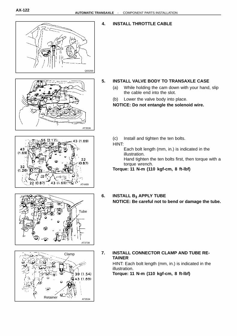
AT4489
AT3738
Tube
AT3534Retainer
Clamp
Q00269
AT3536
4. INSTALL THROTTLE CABLE
5. INSTALL VALVE BODY TO TRANSAXLE CASE(a) While holding the cam down with your hand, slip
the cable end into the slot.
(b) Lower the valve body into place.NOTICE: Do not entangle the solenoid wire.
(c) Install and tighten the ten bolts.HINT:� Each bolt length (mm, in.) is indicated in the
illustration.� Hand tighten the ten bolts first, then torque with a
torque wrench.Torque: 11 N-m (110 kgf-cm, 8 ft-lbf)
6. INSTALL B 3 APPLY TUBENOTICE: Be careful not to bend or damage the tube.
7. INSTALL CONNECTOR CLAMP AND TUBE RE-TAINERHINT: Each bolt length (mm, in.) is indicated in theillustration.Torque: 11 N-m (110 kgf-cm, 8 ft-lbf)
AX-122-AUTOMATIC TRANSAXLE COMPONENT PARTS INSTALLATION
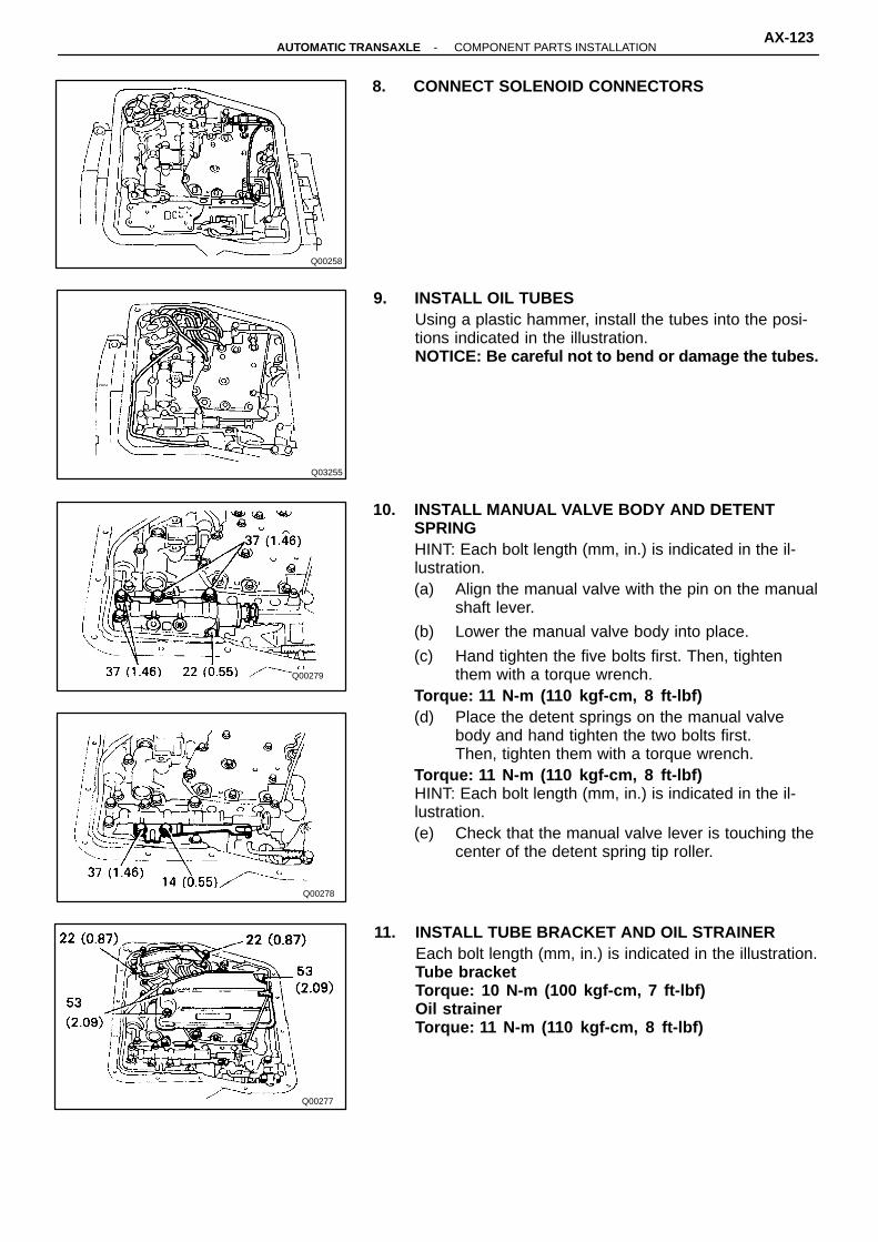
Q00279
Q00278
Q00277
Q03255
Q00258
8. CONNECT SOLENOID CONNECTORS
9. INSTALL OIL TUBESUsing a plastic hammer, install the tubes into the posi-tions indicated in the illustration.NOTICE: Be careful not to bend or damage the tubes.
10. INSTALL MANUAL VALVE BODY AND DETENTSPRINGHINT: Each bolt length (mm, in.) is indicated in the il-lustration.(a) Align the manual valve with the pin on the manual
shaft lever.
(b) Lower the manual valve body into place.
(c) Hand tighten the five bolts first. Then, tightenthem with a torque wrench.
Torque: 11 N-m (110 kgf-cm, 8 ft-lbf)(d) Place the detent springs on the manual valve
body and hand tighten the two bolts first.Then, tighten them with a torque wrench.
Torque: 11 N-m (110 kgf-cm, 8 ft-lbf)HINT: Each bolt length (mm, in.) is indicated in the il-lustration.(e) Check that the manual valve lever is touching the
center of the detent spring tip roller.
11. INSTALL TUBE BRACKET AND OIL STRAINEREach bolt length (mm, in.) is indicated in the illustration.Tube bracketTorque: 10 N-m (100 kgf-cm, 7 ft-lbf)Oil strainerTorque: 11 N-m (110 kgf-cm, 8 ft-lbf)
-AUTOMATIC TRANSAXLE COMPONENT PARTS INSTALLATIONAX-123

Q00256
Q00270
Q00255
AT3741
AT3742
12. INSTALL MAGNETS IN PLACE AS SHOWNNOTICE: Make sure that the magnets do not interferewith the oil tubes.
13. INSTALL OIL PAN WITH NEW GASKET(a) Install a new gasket and oil pan.
(b) Install and torque new seventeen bolts.Torque: 4.9 N-m (50 kgf-cm, 43 in.-lbf)
14. INSTALL NO. 1 VEHICLE SPEED SENSOR(a) Install a new O-ring to the vehicle speed sensor.
(b) Install the vehicle speed sensor to the transaxlecase.
(c) Tighten the bolt.
(d) Connect the sensor connector.
15. INSTALL THROTTLE CABLE RETAINING PLATE
16. INSTALL PARK/NEUTRAL POSITION SWITCH(a) Install the park/neutral position switch to the
manual valve shaft.
(b) Place the new locking plate and tighten the nut.
(c) Stake the nut with locking plate.
(d) Install the two bolts.
AX-124-AUTOMATIC TRANSAXLE COMPONENT PARTS INSTALLATION
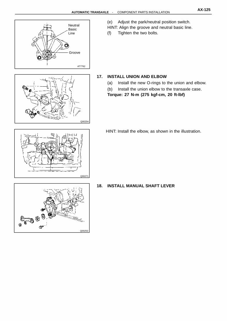
Q00254
Q00271
Q00253
AT7762
Groove
NeutralBasicLine
(e) Adjust the park/neutral position switch.HINT: Align the groove and neutral basic line.(f) Tighten the two bolts.
17. INSTALL UNION AND ELBOW(a) Install the new O-rings to the union and elbow.
(b) Install the union elbow to the transaxle case.Torque: 27 N-m (275 kgf-cm, 20 ft-lbf)
HINT: Install the elbow, as shown in the illustration.
18. INSTALL MANUAL SHAFT LEVER
-AUTOMATIC TRANSAXLE COMPONENT PARTS INSTALLATIONAX-125