Embed Size (px)
Citation preview


FOREWORD The Ministry of Transportation of Ontario firmly believes in good drainage management practice in highway development projects. Good drainage management protects highway infrastructures, property owners and users against flood and drainage-related safety hazards. At the same time, good drainage management protects the land and water environments in watersheds impacted by highway projects and assists in conservation. The ministry believes that good drainage management practice starts with practitioners and decision makers embracing an attitude of respect for the natural environment and willingness to work cooperatively with it in development of highway projects. Practitioners with an understanding of up-to-date concepts and principles of good drainage management practice as well as necessary professional skills to accomplish their work can achieve transportation objectives as well as providing for the natural environment. To these ends, the ministry has developed the MTO Drainage Management Manual to facilitate and direct drainage management practice within the ministry. It will be used by ministry staff of all levels as well as consultants working on provincial highway project assignments. This manual should be used in conjunction with ministry directives which set objectives of practice and general design criteria. Also, this manual is intended to be used within the highway planning and design process and the class environmental assessment process. Two existing publications, namely, MTC Drainage Manual of various dates from 1980 to 1988, and MTO Drainage Management Technical Guidelines dated November, 1989 are now replaced by this manual. Applicable materials in these two publications have been incorporated into the manual. This manual does not set standards for parties and projects external to the ministry. However, the ministry hopes that it will be useful to land developers, municipalities, conservation authorities and their respective consultants in understanding the ministry's drainage management practice. It should also help external parties to understand concerns the ministry may have with regard to drainage management proposals affecting the provincial highway corridor. This manual is the result of the efforts of many, including the MTO Drainage Management Manual Advisory Committee; the Editorial Panel and the writing teams. Participants included both ministry staff and external individuals and organizations. Input from regional offices has notably influenced the outlook and contents of the manual resulting in a document that reflects current operational issues and needs of users. The ministry wishes to thank all who were involved (names appear in the Acknowledgements inside the manual) October 1997
DISCLAIMER
The MTO Drainage Management Manual (the manual) has been developed for use by the Ministry of Transportation of Ontario for its provincial highway projects. Other prospective users should determine for themselves whether the manual is applicable to their practices before they use the manual. The responsibility for the decision is the practitioners'. The ministry expressly disclaims responsibility for any inaccuracy or error which the manual may contain or for the fitness of the manual or the validity of the information contained in the manual for any particular purpose, or for any damage or loss which any person may suffer as a result of reliance upon any statement which the manual may contain.
iii
Preface
The Scope of This Manual This manual has been developed for use by the staff and consultants of the Ministry of Transportation of Ontario (MTO). It covers the practice of drainage management normally associated with the planning and design of highway projects. This manual deals with drainage practice issues such as: • developing solutions to flood plain concerns
associated with the selection of highway horizontal and vertical alignments;
• incorporating watershed drainage concerns when determining tradeoffs between highway alignments, property acquisition, and modifications of streams to accommodate highways; and
• using engineering knowledge of stream morphology to select suitable locations for bridges and culverts.
The manual provides methodology for the hydraulic design of a variety of drainage facilities. These include: roadside ditches, sewers, pavement and bridge deck drainage, stormwater ponds, bridges, culverts, stream channel works, and temporary erosion and sediment control works on construction sites. Generally, applicable standards of practice are included in the discussion of the practice and design methodology. This includes guidance on issues such as acceptable design standards for hydraulic analysis of bridges and culverts. However, to maintain the flexibility of the document specific design policies and criteria are not included in the manual, since policies and
criteria change more often than design methodology. Policies and criteria may also vary with geographical settings, and for a given project special conditions may require flexibility in setting the design criteria. Moreover, this manual may be used by parties external to MTO to whom MTO directives may not apply. MTO users should not be unduly inconvenienced by the absence of specific MTO design policies, referred to as "directives" in the manual, since all MTO offices maintain a complete, up-to-date set of policies which is readily accessible to all staff. It should be noted that specific design objectives, criteria, and options for an individual highway project, including the drainage management components, will be established by the project through the class environmental assessment process. The material presented in this manual provides the general ground work for developing project specific requirements. It is intended to be read and used in this context. Design tools such as computer models, and reference materials mentioned, but not included in the manual, are not part of this document. Such material should be acquired directly from the appropriate suppliers. Transportation engineering is a multidisciplinary field of engineering of which drainage management practice is but one component. Therefore, users of this manual should use this document in conjunction with other applicable manuals and in consultation with the practitioners from the other disciplines. These disciplines include: highway geometric design, structural engineering, environmental planning, and
landscaping, to name a few.
MTO Drainage Management Manual
iv
Finally, it is important to recognize that the Drainage Management Manual is formed around the three basic tasks (i.e. develop study options, preliminary design, and detail design) that are fundamental to the planning and design of highways and their drainage systems. The advantages of this “task-oriented” organization are as follows. • Over time, the mode used to undertake and
deliver the planning and design of highway projects may change. For instance, the planning and design of highways may be “out-sourced” to the private sector. Since the tasks associated with the planning and design of highway drainage systems do not change, all practitioners can use the manual, regardless of whether they are MTO staff or agents who act on behalf of MTO.
• Over time, the process that drives the planning and design of highways may change. Since the manual is not tailored to suit a specific step-by-step process, it can adapt to any process-oriented changes because the fundamental tasks will not change.
Drainage Management Practised in This Manual Drainage management practised by this manual may be described by its basic concept, objectives, and scope of application. The basic concept of drainage management in MTO is adapted from that suggested by the Ministries of the Environment and Energy (MOEE) and Natural Resources (MNR) in the two publications: Integrating Water Management Objectives into Municipal Planning Documents and Subwatershed Planning, 1993. The main point of this concept are as follows. • Watersheds and subwatersheds are the basic
• Planning units for land use planning and resources management.
• The community of living things should be considered along with the physical and chemical factors which form the environment. The main premise is that a wholesome natural environment is achieved over the long term when the environmental considerations are balanced with social and economical relationships.
• The watershed planning unit includes all water processes and factors involved in the hydrological cycle.
• The subwatershed planning process emphasizes the following considerations: protection is preferred to mitigation; understanding of the interactions of the components of the natural environment is encouraged; and watershed planning is expected to be a multidisciplinary and consultative process.
The drainage management objectives of MTO include those required for the protection of the natural environment, as mentioned in the MOEE/MNR publications, and those required to fulfil the provincial transportation business mandate. The transportation objectives include: • provide transportation infrastructures for the
movement of goods and people; • provide efficient and safe operating conditions
of highways in wet weather; • protect transportation infrastructure • investments against damage by floods, scour,
and other long-term hydrologic factors; • protect watershed lands upstream and
downstream of highway right-of-ways from drainage impacts attributable to highways; and
• achieve best return on investment for drainage management in transportation infrastructures.
In applying the watershed planning concept mentioned previously, drainage management in
Preface
v
transportation engineering will focus its scope on watershed areas involving highways directly or indirectly. Watershed areas not involving highways are typically outside the scope of work. Similarly, the subjects of interest and concern are those arising directly or indirectly from highways. Broader subjects not related to a highway, such as creating a ravine picnic area, are typically outside the scope of work. Suggestion for Effective Use of the Manual This manual, by necessity, serves several groups of users and covers the types of drainage facilities usually encountered in transportation engineering. However, it is not necessary for the users to be familiar with the entire manual to get any specific design instructions. The editors have been mindful of the users' concerns and organized the manual in a way that hopefully will satisfy the largest number of users. The manual is divided into four parts, each part being a specific grouping of chapters. Within a chapter, the materials are further organized around each type of design task and are generally self-contained. The headings of the sections within a chapter are worded such that they facilitate locating the information quickly. Part 1 of the manual deals with developing preliminary solutions and highlights the design considerations that should be taken into account early in the highway project stage. Technical details are kept to the minimum. This part can best be used by project managers and others involved in highway preliminary design. Part 2 provides design methodology in a step-by-step approach to facilitate learning of the working details of the design methods. Many design examples are included to illustrate the application of these methods. This part is intended for users who need information on detailed analysis and design techniques.
Part 3 presents the engineering principles and theoretical background of the design methods discussed in Part 2. This part is a convenient reference providing explanations of the principles behind the design methods. It can be used on an "as needed" basis. Part 4 contains design charts that are powerful and time-saving tools for use with the design methods presented in Part 2. A combined index and a glossary are included in the manual to provide guidance for locating specific topics, and to define the major technical terms used in the manual. The glossary and the combined index are bound separately from the other four parts of the manual, so that the user may place them in the more frequently used part of the manual. The Editorial Panel 1997
vi
Acknowledgements
MTO Drainage Management Manual Advisory Committee Gerry McMillan, Chair (1993-95) Ram Dharamdial, Secretary (1993-94) Richard Yeung, Secretary (1995) Remo Bucci, Secretary (1995-97) Robert Bird Cindy Brown (1995-97) Frank Chan (1995-96) Scott Cole (1993-94) Jamie Dougall (1994-97) Brian Goudeseune (1995-97) Don Greer (1995-97) John Hammer Glen Harrington Anna Ilnyckyj (1993-94) John Ding (1993-94) Leonid Mikhailovsky (1993-94) Mark Nykoluk Zdenek Novak Earl Rose John Schaefer (1993-94) Marty Sluyter (1993-94) Andy Stripnieks (1994-97) John Vording Marcia Weaver (1993-94) Wan Wong Charlie Worte
MTO Surveys & Design Office MTO Surveys & Design Office MTO Surveys & Design Office MTO Surveys & Design Office MTO Northern Region MTO Northwestern Region MTO Central Region Cole, Sherman & Associates (UDI)* MTO Environmental Office MTO Southwestern Region Ministry of Natural Resources* Region of Waterloo (MEA)* Harrington & Hoyle Ltd. (NGO)* MTO Maintenance Office Ministry of Natural Resources* MTO Central Region Cole, Sherman & Associates (UDI)* Ministry of Environment & Energy* MTO Eastern Region MTO Northwestern Region MTO Southwestern Region MTO Maintenance Office MTO Highway Planning & Design Develop. MTO Environmental Office MTO Drainage & Hydrology Credit River Conservation Authority (ACAO)* * Also representing Provincial Urban Drainage
Advisory Committee (PUDAC)
Acknowledgements
vii
MTO Drainage Management Manual Editorial Panel Wan M. Wong, P.Eng., Chair
Ministry of Transportation, Ontario Drainage & Hydrology
Richard Yeung, P. Eng., Secretary (1993-95)
Ministry of Transportation, Ontario Drainage & Hydrology
Remo Bucci, P. Eng., Secretary (1995-97)
Ministry of Transportation, Ontario Drainage & Hydrology
Saeed Choudhary, P. Eng.
Ministry of Transportation, Ontario Drainage & Hydrology
Dr. Trevor Dickinson, P. Eng.
School of Engineering University of Guelph
Chris Doherty, P. Eng. Environmental Water Resources Group Ltd.Mississauga, Ontario
Don Greer (1995-97)
Ministry of Natural Resources Peterborough, Ontario
Chris Katopodis, P. Eng.
Freshwater Institute Dept. of Fisheries and Oceans, Winnipeg
Jonathan P'ng, P. Eng. (1995-97)
Ministry of Environment and Energy Toronto, Ontario
Dr. Anthony Smith, P. Eng.
Grand River Conservation Authority Cambridge, Ontario.
MTO Drainage Management Manual Writing Teams Chapter 1 Writers: Dr. Hani Farghaly*, P. Eng.
Remo Bucci*, P. Eng. Chapter 2 Writers:
Chris Doherty, P. Eng., Environmental Water Resources Group Ltd., Mississauga, Ontario
Contributor: Remo Bucci*, P. Eng.
Dr. Trevor Dickinson, P. Eng., School of Engineering, University of Guelph
Stephen F. McNamee, Counsel, MTO. Chapter 3 Writers:
Remo Bucci*, P. Eng. Contributor: Dr. Alex Harrington, P. Eng., Paragon Engineering Ltd., Kitchener, Ontario
Dr. Hani Farghaly*, P. Eng.
Appendix 3C Writer: Michel H. P. Fortin, Michel Fortin Consulting Economist, Guelph, Ontario Chapter 4 Writer:
Examples: Graphics: Sheik Ali*, Sharon Berg*, P. Eng.
Wan M. Wong*, P. Eng. Sheik Ali*, Paul Allen*, Catherine Mainguy*
MTO Drainage Management Manual
viii
Chapter 5 Writer: James Connell*, P.Eng. Sheik Ali* Remo Bucci*, P.Eng.
Contributors: Graphics:
Saeed Choudhary*, P. Eng.
Michael Bender, P. Eng., University of Manitoba Sheik Ali*, Sharon Berg*, P. Eng.
Chapter 6 Writer: Contributor:
Dr. Hani Farghaly*, P.Eng. Saeed Choudhary*, P. Eng. Remo Bucci*, P.Eng.
Chapter 7 Writer: Richard Yeung*, P. Eng.
Chapter 8 Writer: Dr. Hani Faghaly*, P.Eng.
Contributors: Remo Bucci*, P.Eng.
Examples: Graphics:
Ram Dharamdial, P. Eng., Central Region, MTO
James Connell*, P.Eng.
Sheik Ali*, Sharon Berg*, P. Eng. Sheik Ali*, Sharon Berg*, P.Eng.
Chapter 9 Writer: Dr. Victor Galay, P. Eng., Northwest Hydraulics Ltd. Vancouver, B. C.
Chapter 10 Writer: Joe Farwell, P. Eng., Grand River Conservation Authority, Guelph, Ontario
Design Charts Compilers: Sheik Ali*, Sharon Berg*, P.Eng.
Previous Authors The authors of the Drainage Management Manual acknowledge the
contributions of past authors of the MTO Drainage Management Technical Guidelines and the MTO Drainage Manual, as significant portions of these documents were incorporated within the Drainage Management Manual. Specific references are noted in the appropriate chapter.
Technical Editors Dr. Hani Farghaly*, P. Eng. Remo Bucci*, P. Eng.
Legal Adviser Stephen F. McNamee, Counsel, MTO.
Page Editing All staff, Drainage & Hydrology, MTO.
Support Services Library services: Reprographic services:
Greg Barber and Team, MTO Library Publishing Management Office, MTO
* Staff of Drainage and Hydrology, MTO.
ix
Summary
Table of Contents
Foreword Preface Acknowledgement
Part 1
Chapter 1: Introduction to the Manual Table of Contents Purpose of This Chapter Modern Drainage Management Drainage Management and the Highway Planning and Design Process
Chapter 2: Developing Drainage Objectives and Criteria Table of Contents Introduction Considering Possible Drainage Impacts Considering Common Law Principles Considering Statute Law Requirements Considering Documents Supporting Legislative Mandates Considering Consultation With The Public Considering Other Needs References Appendix 2A: Possible Drainage Impacts Appendix 2B: Common Law Principles Appendix 2C: Statute Law Appendix 2D: Agency Mandates Appendix 2E: Documents Supporting Statutory Mandates
Chapter 3: Developing and Evaluating Design Alternatives Table of Contents Purpose of This Chapter
Introduction
MTO Drainage Management Manual
x
Introducing Drainage Design Within The Highway Planning and Design Process A Quick Reference for Developing a Drainage Design Developing a Water Crossing Design Completing a Bridge Crossing Design Completing a Culvert Crossing Design Completing a Stream Channel Modification Design Developing a Surface Drainage Design Completing a Storm Sewer Design Completing a Roadside Ditch Design Completing a Major System Design Developing a Stormwater Management Design Completing a Stormwater Quality Control Facility Design (i.e. Wet Pond, Extended Detention Pond) Completing a Stormwater Quantity Control Facility Design (i.e. Dry Ponds) References Appendix 3A: Hydrologic Computational Procedures Appendix 3B: Hydraulic Computational Procedures Appendix 3C: Evaluation
Part 2
Chapter 4: Surface Drainage Systems Table of Contents Purpose of This Chapter Surface Drainage System Detail Design Process Roadside Ditches Storm Sewers Pavement Drainage Design Examples of Pavement Drainage Bridge Deck Drainage Wet Ponds/Extended Dry Ponds Dry Ponds References Appendix 4A: Summary of Design Methods and Formulas
Appendix 4B: Design Forms
Summary Table of Contents
xi
Chapter 5: Bridges, Culverts and Stream Channels Table of Contents Purpose of this Chapter Detailed Hydraulic Design Flow Conveyance and Backwater Scour Fish Passage in Culverts River Ice Debris Flow Remedial Erosion Measures Stream Channel Sections Stream Channel Lining Materials Stream Channel Bends, Meanders and Alignment Stream Channel Erosion Analysis Methods Hydraulic Design of Fish Habitat Structures Construction Considerations Energy Dissipators Lake Crossings References Appendix 7A: Data Requirements Appendix 7B: Typical Bridges, Culverts and Transition Structures Appendix 7C: Fact Sheets
Chapter 6: Temporary Sediment and Erosion Control
Table of Contents Purpose of This Chapter General Design Considerations Temporary Sediment and Erosion Control Measures Design Example 6.1: Sediment Basin
References

MTO Drainage Management Manual
xii
Chapter 7: Data Sources and Field Investigations
Table of Contents Purpose of This Chapter Primary Data Sources Field Investigation References Appendix 7A: Tables of Data Sources Appendix 7B: Practical Aspects of Field Investigation
Part 3:
Chapter 8: Hydrology, Hydraulics and Stormwater Quality Table of Contents Purpose of This Chapter Precipitation Analysis Watershed Characteristics Affecting Runoff Estimation of Design Floods The Rational Method Regional Frequency Analysis Single Station Frequency Analysis Hydrograph Methods Low Flow Analysis Hydraulic Principles of Drainage Systems Design Flow Measurements and Control Hydraulic Models Culvert Hydraulics Soil Loss Calculations Stormwater Quality References Appendix 8A: Computed Models
Chapter 9: Basic Stream Geomorphology for Highway Applications
Table of Contents General Discussion of Stream Geomorphology Assessment of Stream Stability Example No. 1 Example No. 2 References
Summary Table of Contents
xiii
Chapter 10: Introduction to Soil Bioengineering
Table of Contents Introduction Application of Soil Bioengineering Soil Bioengineering Solutions Practical Experience with Soil Bioengineering References
Part 4:
Design Charts Glossary Combined Index
i
1 Table of Contents
Purpose of This Chapter 1 Modern Drainage Management 2 The Evolution of Drainage Management in Ontario 2
Past Practices (pre 1970's) 2 Further Developments (late 1970's to early 1980's) - Stormwater Management 2 Modern Drainage Management - Watershed-Based Approach (Since early 1990's) 3
Modern Drainage Management in the MTO 3 The MTO Drainage Management Manual 4 Drainage Management and the Highway Planning and Design Process 6 Project Initiation 6 Identification of Project Objectives and Criteria 9 Study Options 9 Preliminary Design 10 Detail Design 10 General Remarks 10 The Highway Project 11 Organization of This Manual 13 List of Figures Figure 1.1: The Highway Preliminary Design Process 7 Figure 1.2: Integration of Drainage Management with the Highway Design Process 8 Figure 1.3: Highway Alternatives and Associated Components of Drainage Options 12 List of Tables Table 1.1: Organization of the Manual and Intended Users 14
Purpose of This Chapter
The purpose of this chapter is to introduce drainage management as it is associated with the highway design process for the Ministry of Transportation of Ontario (MTO). A discussion on the evolution of drainage management (i.e. watershed based approach) is presented to illustrate the changes that have taken place over time in Ontario. The discussion in this chapter is intended to illustrate the rationale for the publication of this new edition of the Drainage Management Manual and show the linkage between modern drainage management and highway planning and design. The information in this chapter is also presented to: • establish the purpose for requiring drainage management in highway planning and design;
and • provide a statement of the mainstream drainage management approach supported by MTO
and adopted in this manual.
1
Modern Drainage Management
The Evolution of Drainage Management in Ontario
Past Practices (pre 1970's) In the past, drainage management activities across Ontario focused on public safety and the protection of site specific capital investments (i.e. the prevention of flooding). This period of time was symbolized by the channelization of natural river/stream channels, and the construction of oversized drainage systems. Cumulative impacts that resulted from development were generally ignored. Consequently, natural receiving drainage systems (i.e. rivers, creeks, lakes) were affected by increases in flooding and erosion, as well as through degradation of water quality. Simply put, it was a period when the importance and function of natural receiving drainage systems was not well understood. This utility-based design methodology was characterised by generally limiting impact assessments to the site of development. Drainage systems were designed to: • convey rainfall runoff, as quickly as possible, off the surface and into storm sewers or
ditches that discharge into the nearest receiving drainage system (i.e. river, stream, ditch, creek, etc.) ;
• minimize flooding of upstream properties; and, • prevent flooding of the development.
Further Developments (late 1970's to early 1980's) - Stormwater Management As adverse impacts of the common approach to drainage management became apparent, the province-wide drainage management practice was revised to include impact assessments that went beyond the site of development. The revised approach had an added focus towards the prevention of downstream flooding and erosion problems. Stormwater management techniques (i.e. dry detention facilities) were applied to reduce peak flow discharges from developments. This approach minimized the erosion and flooding potential of downstream receiving waters. Even though it was apparent that water quality problems still existed, stormwater was not perceived to be a contributor to water quality degradation. Correspondingly, water quality issues were not considered during drainage system planning and design activities. Drainage management during this period was characterized by limiting discharges from the site of development to pre-development levels. The concept of “no increase” in peak flows was
2

Chapter 1: Introduction to the Manual
3
introduced (i.e. pre to post control). Although the overall drainage management practices improved, this approach continued to address drainage management issues on a site-by-site basis. As a result, cumulative impacts to the watershed were ineffectively assessed and other impacts to the watershed system (i.e. to aquatic or terrestrial habitat) were ignored.
Modern Drainage Management - Watershed-Based Approach (Since early 1990's) In the early 1990's, water resource management agencies recognized that drainage management should be practised to account for all impacts within the watershed. In Ontario, the watershed planning approach emerged, with the key principles being that: • the identification of overall watershed objectives should consider all physical, chemical, and
biological parameters that are important to aquatic life and to human health ; • the maintenance of "natural" hydrologic cycles is important to minimize alterations in habitat
diversity, potential impacts to erosion and sedimentation processes, flooding levels, and groundwater supplies; and
• the maintenance of the "natural" river system is critical to the maintenance of "healthy" aquatic environments (i.e. concrete channel systems are not "healthy").
The watershed approach promotes implementation through a multi-disciplinary team (transportation engineers, biologists, landscape architects, water resources engineers and others). Provincially, the Ministry of Natural Resources and the Ministry of the Environment and Energy have shown long term benefits of the watershed-based approach and have promoted the change across Ontario.
Modern Drainage Management in the MTO
The evolution of drainage management within MTO has followed the same path as mainstream practice. In doing so, MTO, within its mandate as steward, owner, and regulator of provincial highways, has endeavoured to implement drainage practices that are beneficial to both the natural environment and the public. This manual has been developed to reflect new developments in drainage management in Ontario, as well as in other jurisdictions, national and international. The basic concept of drainage management in the MTO is adapted from the approach proposed by the Ministries of the Environment and Energy (MOEE) and Natural Resources (MNR), in 1993, in the two publications: Integrating Water Management Objectives into Municipal Planning Documents, and Subwatershed Planning. The main points of this concept are as follows. • Watersheds and subwatersheds are the basic planning units for land use planning and
resources management.
Drainage Management Manual
4
• The community of living things should be considered along with the physical and
chemical factors which form the environment. The main premise is that a wholesome natural environment is achieved over the long term when the environmental considerations are balanced with social and economical relationships.
• The watershed planning unit includes all water processes and factors involved in the hydrological cycle.
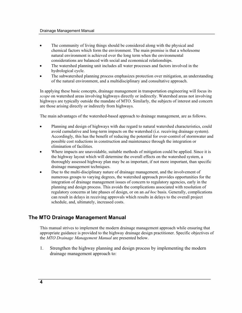
• The subwatershed planning process emphasizes protection over mitigation, an understanding of the natural environment, and a multidisciplinary and consultative approach.
In applying these basic concepts, drainage management in transportation engineering will focus its scope on watershed areas involving highways directly or indirectly. Watershed areas not involving highways are typically outside the mandate of MTO. Similarly, the subjects of interest and concern are those arising directly or indirectly from highways. The main advantages of the watershed-based approach to drainage management, are as follows. • Planning and design of highways with due regard to natural watershed characteristics, could
avoid cumulative and long-term impacts on the watershed (i.e. receiving drainage system). Accordingly, this has the benefit of reducing the potential for over-control of stormwater and possible cost reductions in construction and maintenance through the integration or elimination of facilities.
• Where impacts are unavoidable, suitable methods of mitigation could be applied. Since it is the highway layout which will determine the overall effects on the watershed system, a thoroughly assessed highway plan may be as important, if not more important, than specific drainage management techniques.
• Due to the multi-disciplinary nature of drainage management, and the involvement of numerous groups to varying degrees, the watershed approach provides opportunities for the integration of drainage management issues of concern to regulatory agencies, early in the planning and design process. This avoids the complications associated with resolution of regulatory concerns at late phases of design, or on an ad hoc basis. Generally, complications can result in delays in receiving approvals which results in delays to the overall project schedule, and, ultimately, increased costs.
The MTO Drainage Management Manual This manual strives to implement the modern drainage management approach while ensuring that appropriate guidance is provided to the highway drainage design practitioner. Specific objectives of the MTO Drainage Management Manual are presented below. 1. Strengthen the highway planning and design process by implementing the modern
drainage management approach to:

Chapter 1: Introduction to the Manual
5
• identify and screen drainage management issues at the initial stages of the planning and design process;
• allow flexibility to site highway infrastructures in appropriate locations (e.g. non-sensitive areas);
• plan drainage infrastructure considering existing topography (i.e. natural drainage patterns); and
• consider the use of alternative drainage management techniques while still maintaining the integrity of the highway infrastructure.
2. Recognize that drainage management is dynamic and has evolved into an integrated
resource management approach. 3. Promote a consolidated team approach utilizing the numerous groups and disciplines
that are involved in drainage management within MTO. 4. Ensure consistency in the application of drainage management, as it is practised across
the province. 5. Ensure that regulatory concerns with highway drainage works are not addressed in an ad
hoc manner. 6. Minimize potential liabilities associated with highway drainage works.
Drainage Management and the Highway Planning and
Design Process
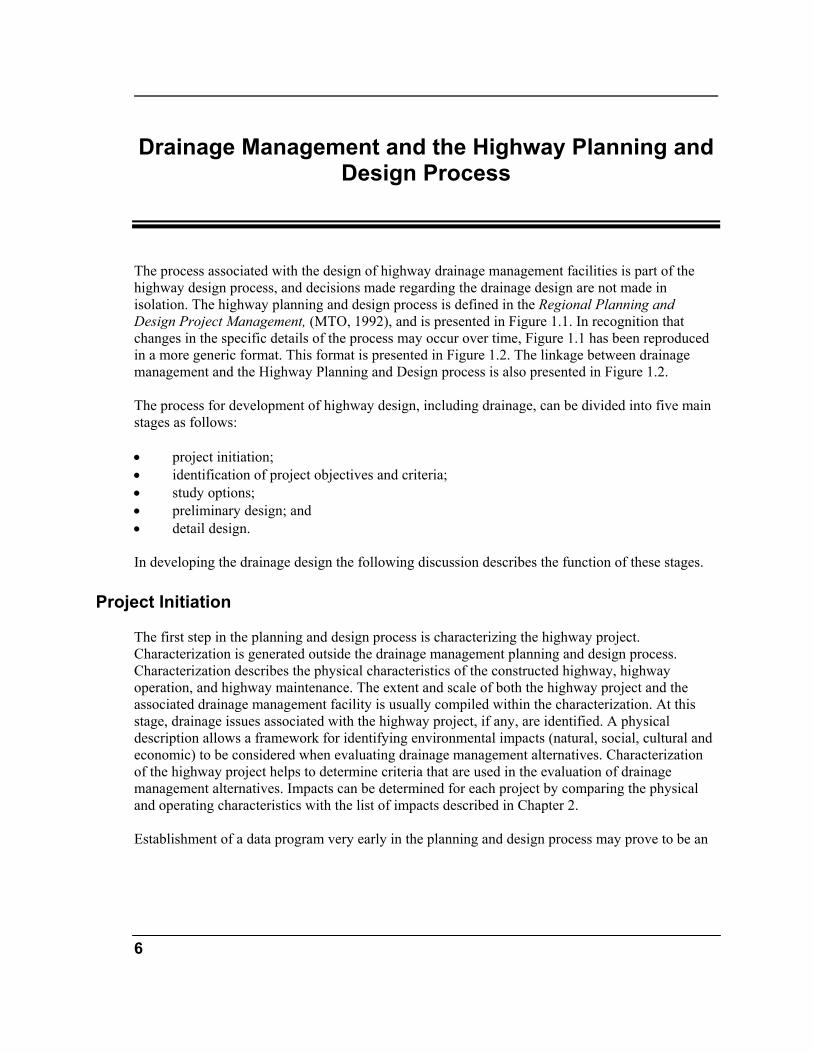
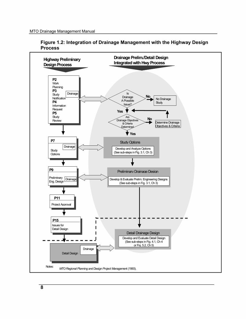
The process associated with the design of highway drainage management facilities is part of the highway design process, and decisions made regarding the drainage design are not made in isolation. The highway planning and design process is defined in the Regional Planning and Design Project Management, (MTO, 1992), and is presented in Figure 1.1. In recognition that changes in the specific details of the process may occur over time, Figure 1.1 has been reproduced in a more generic format. This format is presented in Figure 1.2. The linkage between drainage management and the Highway Planning and Design process is also presented in Figure 1.2. The process for development of highway design, including drainage, can be divided into five main stages as follows: • project initiation; • identification of project objectives and criteria; • study options; • preliminary design; and • detail design. In developing the drainage design the following discussion describes the function of these stages.
Project Initiation The first step in the planning and design process is characterizing the highway project. Characterization is generated outside the drainage management planning and design process. Characterization describes the physical characteristics of the constructed highway, highway operation, and highway maintenance. The extent and scale of both the highway project and the associated drainage management facility is usually compiled within the characterization. At this stage, drainage issues associated with the highway project, if any, are identified. A physical description allows a framework for identifying environmental impacts (natural, social, cultural and economic) to be considered when evaluating drainage management alternatives. Characterization of the highway project helps to determine criteria that are used in the evaluation of drainage management alternatives. Impacts can be determined for each project by comparing the physical and operating characteristics with the list of impacts described in Chapter 2. Establishment of a data program very early in the planning and design process may prove to be an
6
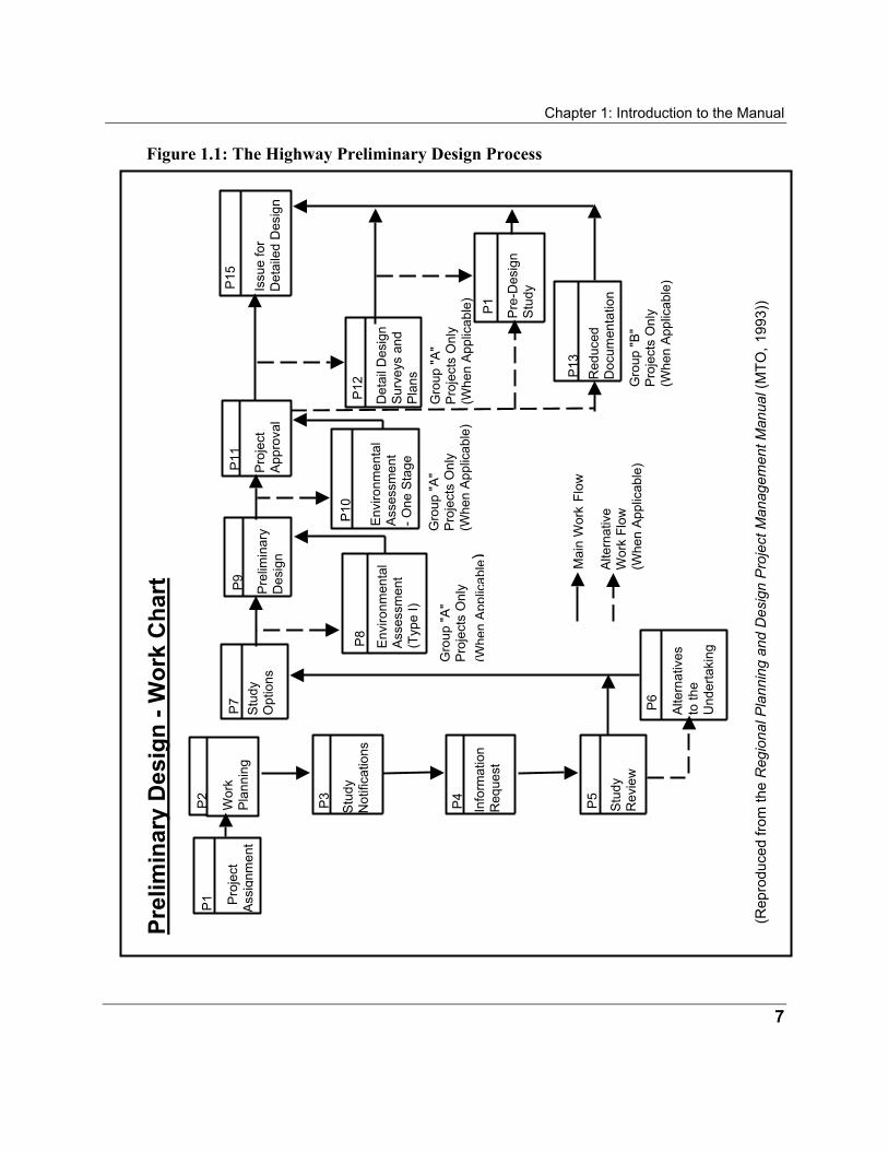
Chapter 1: Introduction to the Manual Figure 1.1: The Highway Preliminary Design Process
Mai
n W
ork F
low
Alte
rnat
ive
Wor
k Fl
ow
(Whe
n Ap
plic
able
)
Prel
imin
ary
Des
ign
- Wor
k C
hart
P12
P1
Gro
up "A
" P
roje
cts
Onl
y (W
hen
Appl
icab
le)
Det
ail D
esig
n S
urve
ys a
nd
Plan
s
Pre
-Des
ign
Stu
dy P1
5
Issu
e fo
r D
etai
led
Des
ign
Red
uced
D
ocum
enta
tion
P13
Gro
up "B
" P
roje
cts
Onl
y (W
hen
Appl
icab
le)
(Rep
rodu
ced
from
the
Reg
iona
l Pla
nnin
g an
d D
esig
n Pr
ojec
t Man
agem
ent M
anua
l (M
TO, 1
993)
)
P8
Env
ironm
enta
l A
sses
smen
t (T
ype
I)
Gro
up "A
" P
roje
cts
Onl
y (W
hen
App
licab
le)
P9
Pre
limin
ary
D
esig
n
P11
Pro
ject
Ap
prov
al
P10
Env
ironm
enta
l A
sses
smen
t - O
ne S
tage
Gro
up "A
" P
roje
cts
Onl
y (W
hen
Appl
icab
le)
P2
Wor
k
Plan
ning
P3
Stu
dy
Not
ifica
tions
P4
Info
rmat
ion
Req
uest
P5
Stu
dy
Rev
iew
P7
Stu
dy
Opt
ions
Alte
rnat
ives
to
the
Und
erta
king
P6
P1
Pro
ject
A
ssig
nmen
t
7
MTO Drainage Management Manual
8
Drainage Prelim./Detail DesignIntegrated with Hwy Process
After MTO Regional Planning and Design Project Management (1993).
Develop and Evaluate Options(See sub-steps in Fig. 4.x, Ch 4)
Detail Drainage DesignDevelop and Evaluate Detail Design
(See sub-steps in Fig. 4.1, Ch 4or Fig. 5.2, Ch 5)
Highway PreliminaryDesign Process
P11Project Approval
P15Issues forDetail Design
Detail DesignDrainage
P2WorkPlanningP3StudyNotificationP4InformationRequestP5StudyReview
Study OptionsDevelop and Analyze Options
(See sub-steps in Fig. 3.1, Ch 3)
P7
StudyOptions
Drainage
Preliminary Drainage Design
Develop & Evaluate Prelim. Engineering Designs(See sub-steps in Fig. 3.1, Ch 3)
P9
PreliminaryEng. Design
Drainage
Notes:
IsDrainage
A PossibleIssue?
No
YesAre
Drainage Objectives& Criteria
DeterminedDetermine DrainageObjectives & Criteria
Yes
No
Drainage
No DrainageStudy
Figure 1.2: Integration of Drainage Management with the Highway Design Process
Chapter 1: Introduction to the Manual efficient and comprehensive means of collecting different types of data, including drainage data. This data will be required in defining the project characteristics. The data program will allow efficient retrieval, storage and manipulation of study data that becomes more specific as the planning and design process evolves. Output from this stage includes physical characteristics of the project that will be utilized to identify potential highway and drainage management facility impacts.
Identification of Project Objectives and Criteria An effective planning and design process requires a clear definition of the facilities objectives and criteria. Significant environmental impacts or high costs may result when inappropriate or vague objectives and criteria are established or informally defined. Objectives and criteria must be defined together. Objectives are steps in achieving the goals and criteria are specific parameters applied to the design. Objectives and criteria are based on the potential watershed impacts of a drainage management facility, laws, codes, policies, standards and guidelines. Criteria are developed through public and agency consultation. Some criteria exclude alternatives while others are used to evaluate the selected alternatives. At the end of this stage drainage objectives and criteria to guide the design process should be documented. It should be noted that specific design objectives, criteria, and options for an individual highway project, including the drainage management components, will be established by the project through the class environmental assessment process. The material presented in this manual provides the general ground work for developing project specific requirements. It is intended to be read and used in this context.
Study Options The first step in the design process is the development of study options for the different highway alternatives being considered. In each case a number of options may be feasible. Each of these options may have a number of associated impacts. Therefore, each option is analyzed and evaluated to eliminate those that do not satisfy the project objectives and criteria identified in the previous step. During this stage, additional information may be identified to assist in further analysis at later stages of development. At the end of this stage, options that merit further investigation through preliminary design should be identified, additional information collected, and all the findings documented.
9
MTO Drainage Management Manual
10
Preliminary Design
The preliminary design stage is a more detailed investigation of the drainage options identified at the study options stage. At this stage, however, a more detailed level of analysis and evaluation is needed to determine the most suitable option(s) that satisfy the design objectives and criteria prior to proceeding to detail design. At the end of this stage documentation of the preferred design(s) may be prepared in the form of a preliminary design report.
Detail Design At this stage the level of design analysis and evaluation of the preliminary design(s) is performed to select the preferred option. The level of analysis and evaluation is much more detailed, and the preferred option selected should satisfy the project objectives and criteria. At the end of this stage the detail design of the preferred drainage management system is documented.
General Remarks
Points to consider when applying the process presented in Figure 1.2 • The process may be iterative. Design requirements, public concerns, scientific
information, natural environment issues, and awareness of environmental processes may change. Consequently, depending on the project, objectives and criteria may have to be modified at any stage of the planning and design process, and new design options considered. This results in the design procedure being an iterative process.
• The process is flexible. All steps in the highway planning and design process are not always required nor necessarily followed in the specific order presented (i.e. as in Figure 1.2). The process is not rigid and need not be divided into separate stages. For instance, the completion of the study options and preliminary design may be done in one step if, for example, only one design option is being considered. The exact sequence of the process will depend on the scale and nature of each project.
• The process includes drainage. Drainage design is a part of the highway planning and design process. Correspondingly, the primary purpose of the Drainage Management Manual is to provide highway design practitioners with guidance on the design of drainage works in support of the highway planning and design process.
• For rehabilitation, drainage works may be “the project”. In most instances, the highway project will involve the design and construction of highway elements associated
Chapter 1: Introduction to the Manual with widenings, realignments, and interchanges. However, in some cases the project may only involve drainage works. For example, a project may involve the analysis of culvert crossings to determine effectiveness, potential liabilities and long term maintenance requirements. Considerations, in such cases, will mostly be drainage related.
• Long term monitoring can determine the effectiveness of a facility in achieving the prescribed objectives and criteria. Monitoring should be conducted from the time of completion of a facility until abandonment. Monitoring includes reconnaissance (e.g. cursory visual observations) and detailed inspections (e.g. condition surveys, performance assessment, etc.). Monitoring can assess the difference between two inspections or cursory visual inspections. Not all MTO highway drainage facilities require detailed inspections. In some cases, reconnaissance may be adequate for ditches, catchbasins, gutters, etc.
• Environmental impacts can be reduced in future designs by modifying design criteria and parameters, to be based on long term monitoring results. In addition, impacts could be reduced through modifying operation and maintenance procedures.
• The Drainage Management Manual is formed around the basic tasks (i.e. develop study options, preliminary design, and detail design) that are fundamental to the planning and design of highways and their drainage systems. The advantages of this “task-oriented” organization are as follows.
• Over time, the mode used to undertake and deliver the planning and design of
highway projects may change. For instance, the planning and design of highways may be “out-sourced” to the private sector. Since the tasks associated with the planning and design of highway drainage systems do not change, all practitioners can use the manual, regardless of whether they are MTO staff or agents who act on behalf of MTO.
• Over time, the process that drives the planning and design of highways may change. Since the manual is not tailored to suit a specific step-by-step process, it can adapt to any process-oriented changes because the fundamental tasks will not change.
The Highway Project The highway project, as illustrated in Figure 1.3, could include the following: • horizontal and vertical realignments; • widening; • interchanges; and • ancillary facilities.
11
MTO Drainage Management Manual
12
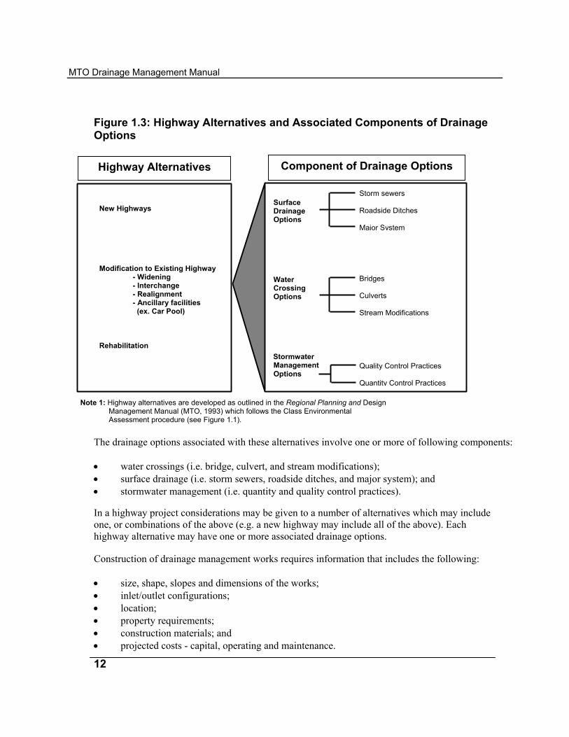
Figure 1.3: Highway Alternatives and Associated Components of Drainage Options
Component of Drainage Options Highway Alternatives
Bridges Culverts Stream Modifications
Quality Control Practices Quantity Control Practices
Storm sewers Roadside Ditches Major System
Surface Drainage Options Water Crossing Options Stormwater Management Options
New Highways Modification to Existing Highway
- Widening - Interchange - Realignment - Ancillary facilities (ex. Car Pool)
Rehabilitation
Note 1: Highway alternatives are developed as outlined in the Regional Planning and Design Management Manual (MTO, 1993) which follows the Class Environmental Assessment procedure (see Figure 1.1).
The drainage options associated with these alternatives involve one or more of following components: • water crossings (i.e. bridge, culvert, and stream modifications); • surface drainage (i.e. storm sewers, roadside ditches, and major system); and • stormwater management (i.e. quantity and quality control practices). In a highway project considerations may be given to a number of alternatives which may include one, or combinations of the above (e.g. a new highway may include all of the above). Each highway alternative may have one or more associated drainage options. Construction of drainage management works requires information that includes the following: • size, shape, slopes and dimensions of the works; • inlet/outlet configurations; • location; • property requirements; • construction materials; and • projected costs - capital, operating and maintenance.
Chapter 1: Introduction to the Manual Development of the above information will consider the following: • environmental impacts of the provincial highway; • location within the watershed; • protection afforded by the drainage management works; • environmental opportunities for improvement (i.e. corridor enhancement); • impacts mitigated by the works; and • impacts created by the works. It is important to note that the environmental impacts associated with a highway project are not limited to the vicinity of the highway right-of-way, but can stretch far upstream and downstream. Therefore, the information requirements for drainage management and assessment of impacts may not be limited to the area in the vicinity of the right-of-way, but, in most cases, will include the entire watershed contributing to the particular area under consideration for drainage works.
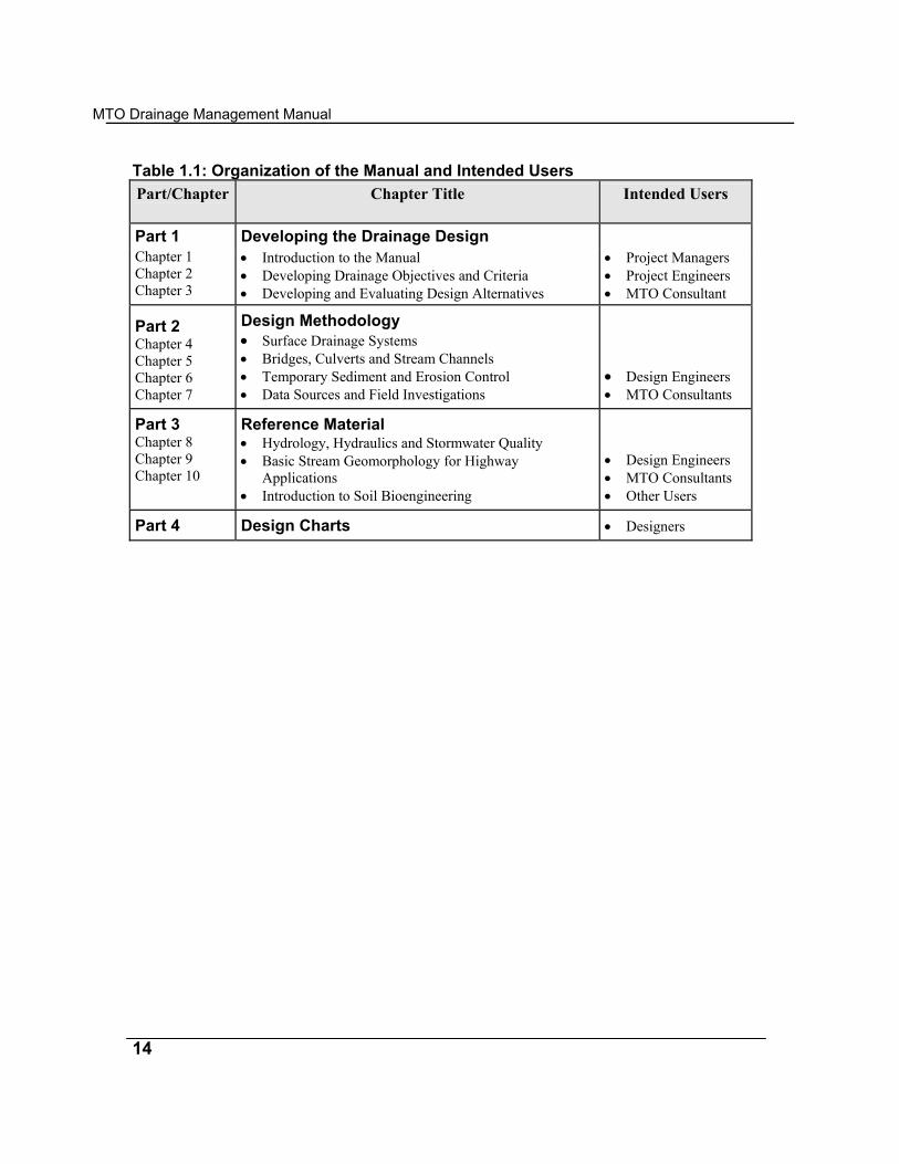
Organization of This Manual This manual provides information for the development of drainage designs for MTO. The manual is divided into four parts, and each part provides different types of information for different users. Table 1.1 shows the contents of each part and the intended users. Part 1 of the manual assists Project Managers in making decisions pertaining to the development of drainage designs as part of a highway project. This part does not provide specific design details, but focuses more on the steps required for achieving the design of drainage works. Chapter 3 was included to outline the planning and design procedure for drainage works, and illustrate the types of activities and analysis associated with drainage designs. Part 2 provides design details for the different components of drainage works associated with highway projects. It illustrates the design methodology with worked design examples. Part 4 includes the design charts referred to in the design examples and other parts of the manual. Part 3 provides the theoretical background on which the design procedures in Parts 1 and 2 are based. This part is intended as a reference to provide further insight on the methods for analysis and design of drainage works discussed in the manual.
13
MTO Drainage Management Manual
14
T a Part/Chapter
Chapter Title
Intended Users
Part 1
Developing the Drainage Design
Chapter 1 Chapter 2 Chapter 3
• Introduction to the Manual • Developing Drainage Objectives and Criteria • Developing and Evaluating Design Alternatives
• Project Managers • Project Engineers • MTO Consultant
Part 2 Chapter 4 Chapter 5 Chapter 6 Chapter 7
Design Methodology • Surface Drainage Systems • Bridges, Culverts and Stream Channels • Temporary Sediment and Erosion Control • Data Sources and Field Investigations
• Design Engineers • MTO Consultants
Part 3 Chapter 8 Chapter 9 Chapter 10
Reference Material • Hydrology, Hydraulics and Stormwater Quality • Basic Stream Geomorphology for Highway
Applications • Introduction to Soil Bioengineering
• Design Engineers • MTO Consultants • Other Users
Part 4
Design Charts
• Designers
able 1.1: Org nization of the Manual and Intended Users
i
2 Table of Contents
Introduction 1 Purpose of This Chapter 1 Definitions: Goals, Objectives and Criteria 1 Developing Objectives and Criteria 2 Considering Possible Drainage Impacts 3 Background 3 Possible Drainage Impacts 3 Considering Common Law Principles 8 Considering Statute Law Requirements 11 Administration of Statute Law 11 Agency Mandates 12 Considering Documents Supporting Legislative Mandates 14 Documents Supporting MTO Legislative Mandate 15 Documents Supporting Legislative Mandate of Regulatory Agencies 15 Considering Consultation with the Public and with Regulatory Agencies 16 Considering Other Needs 17 Detailed Field Inventories and Data Collection 17 Supporting Studies 17 Conflict Resolution 18 References 19 Appendix 2A: Possible Drainage Impacts 25 Potential Hydrologic Impacts, Their Causes and Possible Effects 26
Potential Geomorphologic Impacts, Their Causes and Possible Effects 28
MTO Drainage Management Manual
ii
Potential Soil Erosion Impacts 33 Potential Water Quality Impacts, Their Causes and Possible Effects 34 Potential Impacts on Terrestrial Biota, Their Causes and Possible Effects 37 Potential Impacts on Aquatic Biota, Their Causes and Possible Effects 41 Potential Socioeconomic Impacts, Their Causes and Possible Effects 45 Appendix 2B: Common Law Principles 48 Natural Watercourses 48
Riparian Rights and Obligations 48 Use of Water 49 Interference with Natural Watercourses 50 Diversions 50 Watercourse Crossings 51
Surface Flow 51 Obstruction of Surface Flow 51 Increase of Surface Flow 52 Collection of Surface Flow 52 Surface Flow and the MTO 52
Subsurface Flow 52 Underground Water in a Defined Channel 52 Underground Water not in a Defined Channel 53
Appendix 2C: Statute Law 54 Canadian Environmental Assessment Act, R.S.C., C-37 54 Fisheries Act, R.S.C., 1985, F-14 55 Navigable Waters Protection Act, R.S.C. 1985, N-22 56 Bridges Act, R.S.O. 1990, B.12 57 Environmental Assessment Act , R.S.O. 1990, E.18 57 Environmental Protection Act, R.S.O. 1990, E.19 58 Interpretation Act, R.S.O. 1990, I.11 58 Limitations Act, R.S.O. 1990, L.15 59
Prescriptive Rights 59 Reviewing a Claim to Prescriptive Rights 60
Public Transportation and Highway Improvement Act, R.S.O. 1990, P.50 60 Drainage of Provincial Highways 60 Encroachment Permits 61

Chapter 2: Developing Drainage Objectives and Criteria
iii
Ontario Water Resources Act, R.S.O. 1990, O.40 61 Beds of Navigable Waters Act, R.S.O. 1990, B.4 61 Conservation Authorities Act, R.S.O. 1990, C.27 62 Drainage Act, R.S.O. 1990, D.17 63
Award Drains (Section 3(18)) 64 Mutual Agreement Drains (Section 2) 64 Requisition Drains (Section 3) 64 Petition Drains 65 Petition Requirements 65 Option To Carry Out Drainage Works on Highways 67 Drain Relocation 68 Existing Drain Improvement 68 Obstruction Removal 68 Drainage Works in Unorganized Territories 69 Use of the Drainage Act in Urban Areas 69
Lakes and Rivers Improvement Act, R.S.O. 1990, L.3 69 Local Improvement Act, R.S.O. 1990, L.26 70 Municipal Act, R.S.O. 1990, M.45 70 Planning Act, R.S.O. 1990, c.P.13 71 Public Lands Act, R.S.O. 1990, P.43 71 Tile Drainage Act, R.S.O. 1990, T.8 72 Other Provincial Legislation Related to Drainage 72 Appendix 2D: Agency Mandates 73 A Sample Summary of Agency Mandates Arising from Legislation 74 Appendix 2E: Documents Supporting Statutory Mandates 76 Compilation of Policies, Guidelines, and Regulations of Provincial and Municipal Agencies 77 List of Tables Table 2.1: Examples of Changes in Significant Site Conditions 5 Table 2.2: Possible Drainage Impacts 6 Table 2.3: Examples of Common Law Rights/Obligations-Natural Watercourses 10 Table 2.4: List of Statutes 12 Table 2.5: List of MTO Drainage Directives, Manuals and Protocols 15
MTO Drainage Management Manual
iv
Table 2.6: Regulatory Agencies with Documents Supporting Legislative Mandates 15 Table 2A.1: Potential Hydrologic Impacts, Their Causes and Possible Effects 26 Table 2A.2: Potential Geomorphologic Impacts, Their Causes and Possible Effects 28 Table 2A.3: Potential Soil Erosion Impacts 33 Table 2A.4: Potential Water Quality Impacts, Their Causes and Possible Effects 34 Table 2A.5: Potential Impacts on Terrestrial Biota, Their Causes and Possible Effects 37 Table 2A.6: Potential Impacts on Aquatic Biota, Their Causes and Possible Effects 41 Table 2A.7: Potential Socioeconomic Impacts, Their Causes and Possible Effects 45 Table 2D.1: A Sample Summary of Agency Mandates Arising from Legislation 74 Table 2E.1: Compilation of Policies, Guidelines, and Regulations of Provincial and Municipal Agencies 77
1
Introduction
Purpose of This Chapter The purpose of this chapter is to: • present drainage considerations for developing highway drainage-related objectives
and criteria ; and • provide reference materials. It should be noted that specific design objectives, criteria, and options for an individual highway project, including the drainage management components, will be established by the project through the class environmental assessment process. The material presented in this chapter is intended to be read and used in this context.
Definitions: Goals, Objectives and Criteria Objectives are the premises needed to achieve the goals of a project. Criteria are developed from objectives and are used to measure the ability of an alternative to meet the objectives of a project. Many similar terms such as guidelines, policies, factors or constraints, may also be used to describe the actions outlined for objectives and criteria. Discussions with academic and practising engineers found that each of these terms means something slightly different to each individual. To minimize confusion in this chapter, only the terms objectives and criteria, as defined above, will be used. Goals, broad targets that are to be achieved by the project, are generally linked to objectives and criteria. Although the highway planning and design process does not identify goals as being a specific part of the process, general goals can still be used to identify objectives for highway drainage works. Some general drainage-related goals are stated below and are only included for completeness. • To convey upstream runoff through the highway corridor while minimizing
upstream impacts, downstream impacts and impacts to the highway. • To collect runoff from the highway corridor and convey it to the receiving drainage system
while minimizing upstream impacts, downstream impacts and impacts to the highway. • To meet drainage needs of the highway project.
MTO Drainage Management Manual
2
Developing Objectives and Criteria
It is recognized that the highway project will define objectives and criteria. Therefore, the objectives and criteria associated with drainage management should be developed in conjunction with, and be incorporated into, those of the highway project. This approach is consistent with the integrated nature of the highway planning and design process, as it is presented in Figure 1.1 of Chapter 1. Some other general points regarding the development of drainage criteria or objectives are as follows. • Drainage objectives should remain consistent throughout the highway planning and design
process. • Drainage criteria may change as the evaluation of drainage options progresses. At first,
a small set of readily measurable criteria may be used. Once the short list of options is identified, more detailed information may be required to distinguish between the options. The overall procedure will be iterative.
• Drainage criteria will also vary according to the type of drainage option. For instance, drainage associated with the larger scale highway projects will require criteria to measure general impacts to watershed features, uses and characteristics. These criteria will emphasize avoidance of significant impacts.
• It is recommended that objectives and criteria be sorted according to impacts and then sorted according to the type of drainage works.
The planning and design of most drainage works will require an interdisciplinary team of professionals to establish and modify specific drainage objectives and criteria. Modification will generally result from consultation with the public and with regulatory agencies. Drainage objectives and criteria can be developed by considering the following: • possible drainage impacts; • common law principles; • statute law requirements; • documents supporting legislative mandates (e.g. policies, guidelines, manuals, etc.); • consultation with the public and with regulatory agencies; and • other needs (i.e. data collection, support studies and conflict resolution). The confirmation of the selected drainage objectives and criteria should have the support of both the public and regulatory agencies. This reduces the likelihood of the drainage objectives and criteria being questioned after they have been applied, which can have both schedule and cost implications for a project.
3
Considering Possible Drainage Impacts
Background Possible drainage impacts are presented as a preparatory step and can be used as a “screening tool” to provide the user with a quick method for identifying possible drainage impacts. The identified impacts can then be used as a guide for determining the scope and nature of the drainage objectives and criteria required for highway projects. Specific drainage objectives and criteria are determined by reviewing the considerations for developing drainage objectives and criteria that are presented in the subsequent sections. Appropriate guidance and information sources related to these considerations are presented within. Due to the interdisciplinary nature associated with developing drainage objectives and criteria, it is intended that this chapter clearly outline the areas where consultation with, and involvement of, other professional disciplines is required. Information that is not directly related to drainage is included only for: • information purposes; • to familiarize the drainage practitioner with the language of other disciplines; and • to familiarize the drainage practitioner with the issues that are shared between the different
disciplines. Solutions to impacts that are directly related to the drainage design are discussed in Chapter 3. For technical details refer to Chapter 4 or Chapter 5, in Part 2 of this manual. Solutions to impacts, not directly related to the drainage design, are outside the scope of this manual and are discussed in other MTO documents such as: • the Environmental Manual, Fisheries (Working Draft); or • the Environmental Manual, Sediment and Erosion Control (Working Draft). When designing solutions to drainage related impacts, advantages gained through the interdisciplinary team approach cannot be overstressed.
Possible Drainage Impacts Impacts, which can occur as a result of alterations in drainage associated with a highway project, are triggered by changes in one or more of the following on-site conditions:
MTO Drainage Management Manual
4
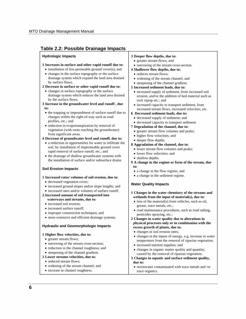
• ground cover; • topography; • surface drainage systems; and • contaminant inputs; Table 2.1 provides examples of these possible changes in site conditions. These changes have the potential to cause a variety of possible impacts. As an aid to understanding the potential impacts of highway drainage, impacts have been sorted into seven categories: • hydrology; • soil erosion; • hydraulics and geomorphology; • water quality; • terrestrial biota; • aquatic biota; and • socioeconomic. Table 2.2 presents a summary of possible drainage impacts along with possible causes. A more detailed listing of the causes and effects is presented in Appendix 2A, of this chapter. In reviewing Table 2.2 and Appendix 2A, it is important to note the following. • There are a great many potential impacts associated with changes in highway drainage. • The potential impacts are highly interdependent. A change in drainage can alter hydrology,
which can alter river hydraulics and geomorphology, which in turn, can alter sediment loads and aquatic habitat. An understanding of the linkages between impacts is important when selecting the most appropriate mitigating measure.
• Some impacts are local; some are regional in nature.

Chapter 2: Developing Drainage Objectives and Criteria
5
Table 2.1: Examples of Changes in Significant Site Conditions Ground Cover
The original vegetative cover(s) (trees, brush, agricultural crops, etc.) may be removed, and/or new ground cover(s) (pavement, rock, grasses etc.) may be installed.
Topography
Land slopes may be increased, decreased or altered in direction with excavation and/or filling to create highway subgrade, interchanges etc. and bridge abutments and approach ramps.
Surface Drainage System
The natural pattern of surface runoff and/or the continuity of overland flow paths may be altered by highway rights-of-way, profiles and barriers (safety guide rails, noise barriers etc.), and retention and deposition ponds. Physical characteristics of streams and waterways (length, cross-section size and shape, roughness etc.) may be altered in the vicinity of water crossings due to stream modifications/ diversions, temporary works (fording, coffer dams etc.) and design features such as abutments, piers, dykes and groynes.
Contaminant Inputs
The presence of highway traffic and road maintenance introduces the opportunity for many contaminants to enter the adjacent environment, including the drainage system (e.g. deicing compounds such as chlorides, sodium, calcium, ferric ferrocyanide, sodium ferrocyanide, and chromate of phosphate; nutrients and herbicides; grease, oil paraffins and heavy metals such as cadmium, chromium, copper, lead, magnesium, manganese, nickel and zinc from road runoff; minerals and chemicals from construction, refuelling areas, equipment storage areas, parking areas and stockpiles; chemicals and fuel from spills).
MTO Drainage Management Manual
6
Table 2.2: Possible Drainage Impacts Hydrologic Impacts 1 Increases in surface and other rapid runoff due to:
• installation of less permeable ground cover(s); and • changes in the surface topography or the surface
drainage system which expand the land area drained by surface flows.
2 Decrease in surface or other rapid runoff due to: • changes in surface topography or the surface
drainage system which reduces the land area drained by the surface flows.
3 Increase in the groundwater level and runoff , due to: • the trapping or impoundment of surface runoff due to
changes within the right-of-way such as road profiles, etc.; and
• reduction in evapotranspiration by removal of vegetation (with roots reaching the groundwater) from significant areas.
4 Decrease of groundwater level and runoff, due to: • a reduction in opportunities for water to infiltrate the
soil, by installation of impermeable ground cover rapid removal of surface runoff, etc.; and
• the drainage of shallow groundwater systems with the installation of surface and/or subsurface drains
Soil Erosion Impacts 1 Increased rates/ volumes of soil erosion, due to:
• decreased vegetation cover; • increased ground slopes and/or slope lengths; and • increased rates and/or volumes of surface runoff.
2. Increased amount of soil transported into waterways and streams, due to:
• increased soil erosion; • increased surface runoff; • improper construction techniques; and • more extensive and efficient drainage systems.
Hydraulic and Geomorphologic Impacts 1 Higher flow velocities, due to:
• greater stream flows; • narrowing of the stream cross-section; • reduction in the channel roughness; and • steepening of the channel gradient.
2 Lower streams velocities, due to: • reduced stream flows; • widening of the stream channel; and • increase in channel roughness.
3 Deeper flow depths, due to:
• greater stream flows; and • narrowing of the stream cross-section.
4 Shallower flow depths, due to: • reduces stream flows; • widening of the stream channel; and • steepening of the channel gradient.
5 Increased sediment loads, due to: • increased supply of sediment, from increased soil
erosion, and/or the addition of bed material such as rock riprap etc.; and
• increased capacity to transport sediment, from increased stream flows, increased velocities, etc.
6 Decreased sediment loads, due to: • decreased supply of sediment; and • decreased capacity to transport sediment.
7 Degradation of the channel, due to: • greater stream flow volumes and peaks; • higher flow velocities; and • deeper flow depths.
8 Aggradation of the channel, due to: • lesser stream flow volumes and peaks; • lower flow velocities; and • shallow depths.
9 A change in the regime or form of the stream, due to: • a change in the flow regime; and • a change in the sediment regime.
Water Quality Impacts 1 Changes in the water chemistry of the streams and
wetlands from the input of material(s), due to: • loss of the material(s) from vehicles, such as oil,
grease, trace metals, etc.; • road maintenance procedures, such as road salting,
pesticides spraying, etc.; 2 Changes in water quality due to alterations in
physical processes only or in combination with the excess growth of plants, due to: • changes in soil erosion rates; • changes in the inputs of energy, e.g. increase in water
temperature from the removal of riparian vegetation; • increased nutrient supplies; and • changes in organic matter quality and quantity,
caused by the removal of riparian vegetation. 3 Changes in aquatic and surface sediment quality,
due to: • stormwater contaminated with trace metals and /or
trace organics.

Chapter 2: Developing Drainage Objectives and Criteria
7
Table 2.2: Possible Drainage Impacts (continued) Impacts on Terrestrial Biota 1 Losses or reductions in native or exotic plant species
or communities associated with terrestrial ecosystems, due to: • direct removal or injury of plant cover; • changes in the micro-climate, such as the removal of
tree canopy; • changes in shallow groundwater systems; and • increased soil salinity.
2 Expansion in the range of native or exotic plant species or communities associated with terrestrial ecosystems, due to: • intentional or accidental introduction of exotic plant
biota; • changes in micro-climate; • changes in shallow groundwater systems; and • increased soil salinity.
3 Losses of animal species or communities associated with terrestrial ecosystems, due to: • barriers in migration to animal movement, such as
road profile changes within the right-of-way; and • loss of habitat features required by animals.
4 Expansion in the ranges of animal species or communities associated with terrestrial ecosystems, due to: • loss of predators; and • increased habitat.
5 Disruption in the relationship between different components of terrestrial ecosystems, due to: • planted roadside vegetation.
Impacts on Aquatic Biota 1 Losses or reductions in plant species or
communities associated with tributary or wetland ecosystems, due to: • direct removal or injury of plant cover.
2 Expansion in the range of native species or communities associated with tributary or wetland ecosystems, due to: • increase supply of nutrients; • loss of sensitive native species; and • drainage works.
3 Losses or reduction in animal species or
communities associated with tributary or wetland ecosystems, due to: • acute stormwater toxicity; • chronic or non-lethal effects associated with
stormwater discharges or through contamination of aquatic sediments; and
• loss of habitat features required by animals. 4 Expansion in the range of animal species associated
with tributary or wetland ecosystems, due to: • degraded habitat.
5 Disruption in the relationship between different components of tributary or wetland ecosystems, due to: • changes in the plant species and communities; and • creation of artificial salt licks.
Socioeconomic Impacts 1 Loss of life and/or property, due to:
• flood caused by hydrologic and/or geomorphologic changes.
2 Loss or agricultural resources, due to: • flooding; • phytotoxicity of wet deposition, such as salt and
particulate matter etc.; and • alterations in drainage.
3 Loss of archeological and historic importance of native and non-native peoples, due to: • loss or damage to sites of cultural or historic
importance to native and non-native peoples. 4 Increased costs of water treatment, due to:
• impairment of water quality. 5 Loss of beneficial or recreational uses of terrestrial
or aquatic biota, due to: • loss of fish or bird species.
6 Loss of aesthetics, due to: • loss of terrestrial and aquatic plants; and • loss of walking or hiking paths.
7 Loss of biodiversity, due to: • loss or reduction of animal and plant species.
8
Considering Common Law Principles
Common law is a body of principles based on long standing usages and customs, and on court decisions recognizing, affirming and enforcing such usages and customs. Common law, therefore, is largely a matter of precedent; the precedents can be modified as customs change and new practices arise. Common law principles: • always apply unless enlarged, modified or superseded by statute law; • give regard to current societal standards (i.e. what is deemed to be reasonable conduct in a
given set of circumstances as well as reasonable expectations concerning what should or should not be foreseeable to a prudent person), and therefore are evolving; and
• are based on judgements rendered by the courts. Since each particular highway project is unique and requires a slightly different solution, the development of drainage design criteria by lay persons interpreting previous court decisions may not always be appropriate. The practitioner is urged to obtain legal advice for all drainage matters that may lead to court judgements. Each drainage situation must be evaluated on its own merit. Sound judgement, proper design procedures and adequate documentation are very important. When reviewing this section consider that: • it is primarily written for MTO’s staff (others may use this sections for reference,
however, they are responsible for determining its applicability to their practice); • it identifies the more important legal aspects of the design, construction and maintenance of
highway drainage facilities, and provides a practical introduction to drainage law; • it is not intended as an authoritative legal guide, but to give MTO staff a reasonable working
knowledge of the subject; • it should not be used to base legal advice or make legal decisions; and • it is not intended as a substitute for legal counsel. When reviewing common law principles, the type of water flow involved in any problem must be identified. Following this logic, common law, as it relates to highway drainage management, can be divided into the following subsections. • Natural Watercourses:
• Riparian Rights and Obligation; • Use of Water; • Interference with Natural Watercourses; • Diversions; and
Chapter 2: Developing Drainage Objectives and Criteria
9
• Watercourse Crossings. • Surface Flow:
• Obstruction of Surface Flow; • Increase of Surface Flow; • Collection of Surface Flow; and • Surface Flow and the MTO.
• Subsurface Flow:
• Underground Water in a Defined Channel; and • Underground Water not in a Defined Channel.
Table 2.3 presents examples of common law rights and obligations related to natural watercourses. Further details are discussed in Appendix 2B. It is recognized that the obligations of a land owner who is seeking a sufficient outlet for drainage, have common law and statute law implications and could be included as part of the discussion on common law. However, for the purposes of this manual, the discussion on this issue has been limited to the presentation on statute law (refer to the subsequent section and to Appendix 2C). Note: The discussion on Common Law contained within this chapter was taken from the original
source (Madill, R.A., Harris, J.D., Tretjakoff, A. and McIlmoyle Q.C., A. B. (May 1980)) and modified.

MTO Drainage Management Manual
10
Table 2.3: Examples of Common Law Rights/Obligations-Natural
Watercourses
Attributes Rights Obligations • Created by nature. • Visible bed and confining
banks. • Sufficient flow to give it
substantial existence. • Riparian owners are those
whose lands abut a natural watercourse. Bogs and swamps are not natural watercourses.
• Can include: • The valley through which a
stream runs; and • A permanent artificial
channel such as the Rideau Canal.
• Does Not Include: • Artificial ditches.
• Includes • Rainwater, melting snow,
spring water; • Water diffuses over the
surface and does not follow a defined channel;
• Temporary and casual nature. Water disperses over the ground through percolation, evaporation or natural drainage; and
• Does not gather or form any more definite body of water other than a bog or marsh.
• Riparian owners have the following rights with
regard to natural watercourses across their lands: • To drain catchment area lands to the watercourse
as long as flows do not exceed the capacity of the lower channel in its natural state;
• To discharge collected water via drains or ditches to the watercourse as long as flows do not exceed the capacity of the lower channel in its natural state;
• To make extraordinary use of water (e.g. operation of a mill) as long as the quantity and quality are not diminished;
• To have water flow to him/her in its natural state via the watercourse; and
• To use the stream water for domestic or natural purposes.
• Higher lands can drain onto lower lands. • A lower land owner does not have to receive water
from higher lands as long as the lower land owner does not injure an adjacent land owner when exercising the right not to receive surface water.
• A land owner : • Can collect and drain surface water but must have
a sufficient outlet. • Can dig a pond to retain water; • Can build a dyke as long as the dyke does not
collect or concentrate flow; and • Can raise the level of the lower land above the
higher land. Cannot direct high land water to lands that did not have water before.
• May not bring waters that
have not fallen within the watershed to the stream.
• May not sell or assign the right to drain into a watercourse.
• To ensure a sufficient outlet where there is interference with a natural watercourse.
• To obtain a water taking permit from MOEE for withdrawals greater than 50,000 L/day.
• Enclosures cannot reduce the watercourse capacity.
• Must accept increased flows as long as it results from reasonable use.

11
Considering Statute Law Requirements Statute law is established by a legislative body and set down in a formal document. Statute law can evolve (enlarged and modified) from common law (court made law) to correct inadequacies in common law. There are many statutes containing provisions which relate to drainage. Some statutes bind the Crown, while others do not. The statutes that relate to highway drainage, binding the Crown and applicable to MTO, are identified on Table 2.4. For a more detailed discussion on each statute, refer to Appendix 2C. Since each particular highway project is unique and requires a slightly different solution, the development of drainage design criteria by lay persons interpreting statute law requirements may not always be appropriate. The practitioner is urged to obtain legal advice for all drainage matters that may lead to court judgements. Each drainage situation must be evaluated on its own merit. Sound judgement, proper design procedures and adequate documentation are very important. When reviewing this section consider that it: • identifies the more important legal aspects of the design, construction and maintenance of
highway drainage facilities, and provides a practical introduction to drainage law; • is not intended as an authoritative legal guide, but to give MTO staff a reasonable working
knowledge of the subject; and • should not be used to base legal advice or make legal decisions.
Administration of Statute Law Federal and provincial statues provide for the administration of the requirements of legislation through government agencies in the form of federal departments, provincial ministries, conservation authorities, crown corporations, boards, and municipal or regional departments. Administrative authority is sometimes delegated from a higher to lower level of government. The agencies with which authority rests are the “mandated agencies”. In addition to the role of the mandated agency in granting approvals, other agencies may be assigned the role of a commenting agency in the approval review process.
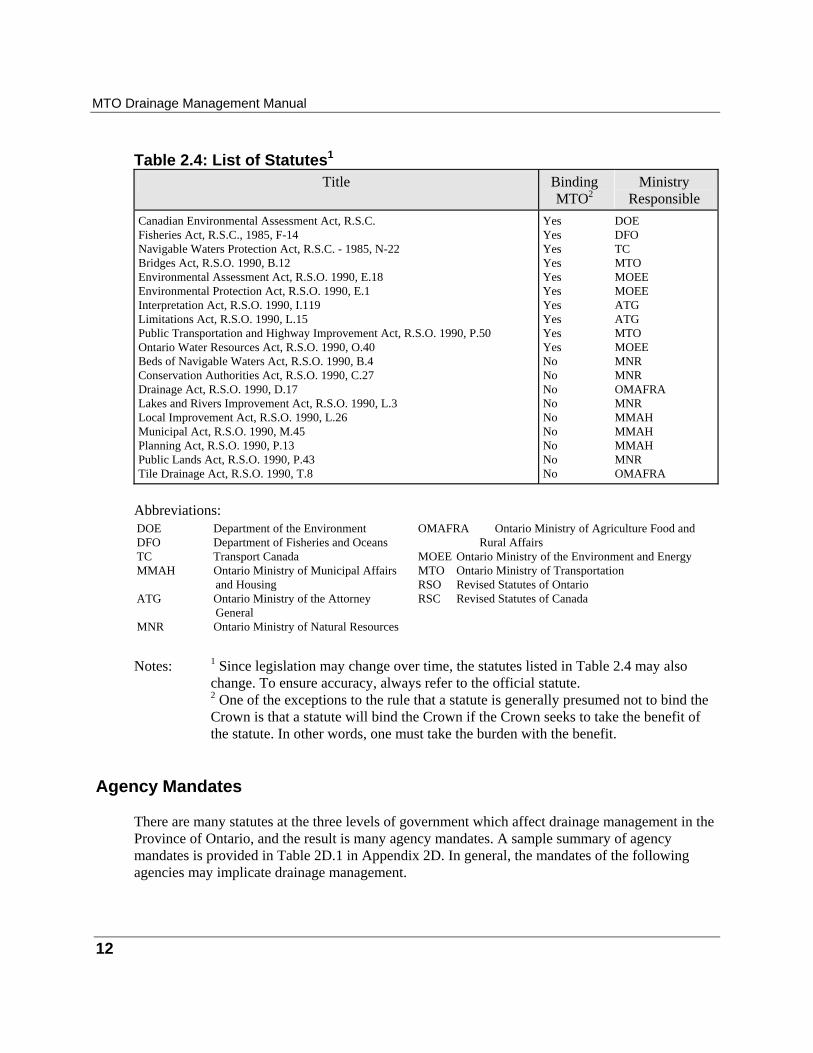
MTO Drainage Management Manual
12
Table 2.4: List of Statutes1
Title
Binding MTO2
Ministry
Responsible Canadian Environmental Assessment Act, R.S.C. Fisheries Act, R.S.C., 1985, F-14 Navigable Waters Protection Act, R.S.C. - 1985, N-22 Bridges Act, R.S.O. 1990, B.12 Environmental Assessment Act, R.S.O. 1990, E.18 Environmental Protection Act, R.S.O. 1990, E.1 Interpretation Act, R.S.O. 1990, I.119 Limitations Act, R.S.O. 1990, L.15 Public Transportation and Highway Improvement Act, R.S.O. 1990, P.50 Ontario Water Resources Act, R.S.O. 1990, O.40 Beds of Navigable Waters Act, R.S.O. 1990, B.4 Conservation Authorities Act, R.S.O. 1990, C.27 Drainage Act, R.S.O. 1990, D.17 Lakes and Rivers Improvement Act, R.S.O. 1990, L.3 Local Improvement Act, R.S.O. 1990, L.26 Municipal Act, R.S.O. 1990, M.45 Planning Act, R.S.O. 1990, P.13 Public Lands Act, R.S.O. 1990, P.43 Tile Drainage Act, R.S.O. 1990, T.8
Yes Yes Yes Yes Yes Yes Yes Yes Yes Yes No No No No No No No No No
DOE DFO TC MTO MOEE MOEE ATG ATG MTO MOEE MNR MNR OMAFRA MNR MMAH MMAH MMAH MNR OMAFRA
Abbreviations: DOE Department of the Environment DFO Department of Fisheries and Oceans TC Transport Canada MMAH Ontario Ministry of Municipal Affairs and Housing ATG Ontario Ministry of the Attorney General M NR Ontario Ministry of Natural Resources
OMAFRA Ontario Ministry of Agriculture Food and
Rural Affairs MOEE Ontario Ministry of the Environment and Energy MTO Ontario Ministry of Transportation RSO Revised Statutes of Ontario RSC Revised Statutes of Canada
Notes: 1 Since legislation may change over time, the statutes listed in Table 2.4 may also
change. To ensure accuracy, always refer to the official statute. 2 One of the exceptions to the rule that a statute is generally presumed not to bind the Crown is that a statute will bind the Crown if the Crown seeks to take the benefit of the statute. In other words, one must take the burden with the benefit.
Agency Mandates There are many statutes at the three levels of government which affect drainage management in the Province of Ontario, and the result is many agency mandates. A sample summary of agency mandates is provided in Table 2D.1 in Appendix 2D. In general, the mandates of the following agencies may implicate drainage management.
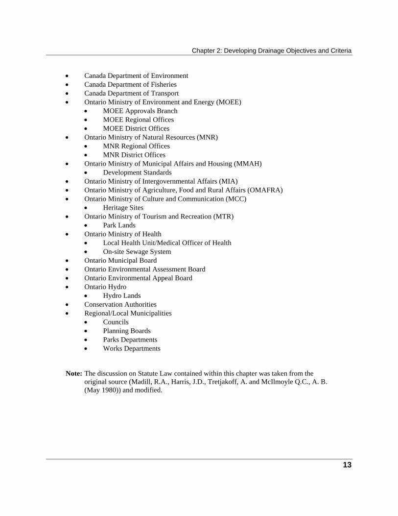
Chapter 2: Developing Drainage Objectives and Criteria
13
• Canada Department of Environment • Canada Department of Fisheries • Canada Department of Transport • Ontario Ministry of Environment and Energy (MOEE)
• MOEE Approvals Branch • MOEE Regional Offices • MOEE District Offices
• Ontario Ministry of Natural Resources (MNR) • MNR Regional Offices • MNR District Offices
• Ontario Ministry of Municipal Affairs and Housing (MMAH) • Development Standards
• Ontario Ministry of Intergovernmental Affairs (MIA) • Ontario Ministry of Agriculture, Food and Rural Affairs (OMAFRA) • Ontario Ministry of Culture and Communication (MCC)
• Heritage Sites • Ontario Ministry of Tourism and Recreation (MTR)
• Park Lands • Ontario Ministry of Health
• Local Health Unit/Medical Officer of Health • On-site Sewage System
• Ontario Municipal Board • Ontario Environmental Assessment Board • Ontario Environmental Appeal Board • Ontario Hydro
• Hydro Lands • Conservation Authorities • Regional/Local Municipalities
• Councils • Planning Boards • Parks Departments • Works Departments
Note: The discussion on Statute Law contained within this chapter was taken from the
original source (Madill, R.A., Harris, J.D., Tretjakoff, A. and McIlmoyle Q.C., A. B. (May 1980)) and modified.
14
Considering Documents Supporting Legislative Mandates
The mandates of agencies, drawn through statutes, are implemented through the use of supporting documents. Approvals are generally sought in the context of these documents. Some forms of these support documents are discussed below. • Policies such as MTO Directives and policies of other agencies may implicate
drainage works. An example of a Provincial Policy document is the Natural Heritage Policy Statement.
• Protocols are agreements between two or more government ministries or agencies to define legal and administrative processes for MTO undertakings. An example of a protocol is the MTO/MNR/DFO Fisheries Protocol.
• Guidelines and manuals are prepared by various ministries to explain how a subject matter should be addressed, and provide resource reference information and suggested approaches.
• Codes/Standards must be followed when generating water crossing options. The Ontario Highway Bridge Design Code (OHBDC) is an example of a code.
• Drainage plans include watershed plans, subwatershed plans, master environmental servicing plans, and site plans that are prepared by agencies external to MTO. Criteria and objectives can be abstracted from these documents. Only plans that have been endorsed by MTO should be used to abstract objectives and criteria. Watershed or subwatershed plans, for areas that are applicable to MTO right-of-ways, typically include the following information that could be utilized to develop criteria:
• areas that must be protected, rehabilitated and enhanced; • areas that can be developed in a manner compatible with subwatershed objectives; • policy/guidelines to direct development planning and design; • directives for stormwater management and groundwater plans, and
other studies/designs for specific areas; and • design, function, siting and timing of facilities.
In addition to criteria, watershed/subwatershed plans will undertake baseline inventories that may provide information on areas that could potentially be impacted by MTO highways and drainage systems. Baseline inventories include stream erosion, water quality, terrestrial habitats, groundwater, wetlands, environmentally significant and sensitive areas, woodlots, etc.
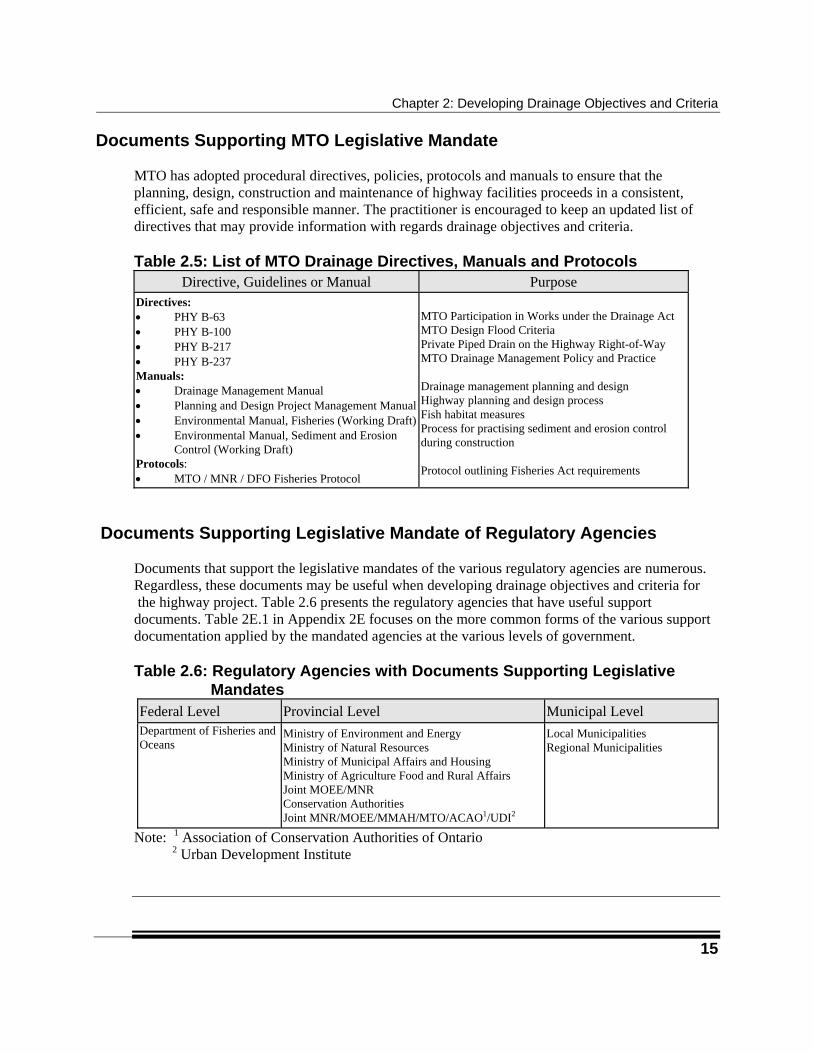
Chapter 2: Developing Drainage Objectives and Criteria
15
Documents Supporting MTO Legislative Mandate
MTO has adopted procedural directives, policies, protocols and manuals to ensure that the planning, design, construction and maintenance of highway facilities proceeds in a consistent, efficient, safe and responsible manner. The practitioner is encouraged to keep an updated list of directives that may provide information with regards drainage objectives and criteria. Table 2.5: List of MTO Drainage Directives, Manuals and Protocols
Directive, Guidelines or Manual
Purpose Directives: • PHY B-63 • PHY B-100 • PHY B-217 • PHY B-237 Manuals: • Drainage Management Manual • Planning and Design Project Management Manual• Environmental Manual, Fisheries (Working Draft)• Environmental Manual, Sediment and Erosion
Control (Working Draft) Protocols: • MTO / MNR / DFO Fisheries Protocol
MTO Participation in Works under the Drainage Act MTO Design Flood Criteria Private Piped Drain on the Highway Right-of-Way MTO Drainage Management Policy and Practice Drainage management planning and design Highway planning and design process Fish habitat measures Process for practising sediment and erosion control during construction Protocol outlining Fisheries Act requirements
Documents Supporting Legislative Mandate of Regulatory Agencies Documents that support the legislative mandates of the various regulatory agencies are numerous. Regardless, these documents may be useful when developing drainage objectives and criteria for the highway project. Table 2.6 presents the regulatory agencies that have useful support documents. Table 2E.1 in Appendix 2E focuses on the more common forms of the various support documentation applied by the mandated agencies at the various levels of government. Table 2.6: Regulatory Agencies with Documents Supporting Legislative
Mandates Federal Level
Provincial Level
Municipal Level
Department of Fisheries and Oceans
Ministry of Environment and Energy Ministry of Natural Resources Ministry of Municipal Affairs and Housing Ministry of Agriculture Food and Rural Affairs Joint MOEE/MNR Conservation Authorities Joint MNR/MOEE/MMAH/MTO/ACAO1/UDI2
Local Municipalities Regional Municipalities
Note: 1 Association of Conservation Authorities of Ontario 2 Urban Development Institute
16
Considering Consultation with the Public and with Regulatory Agencies
Consultation with the public and with regulatory agencies can be used to develop drainage objectives and criteria, and can identify conflicting external agency criteria. Regulatory agency/public consultation can provide the following: • opportunities for agency/public concern and comment on drainage issues; • additional project information related to drainage; • property owner needs that have to be addressed by the drainage works; and • identification of required drainage commitments to agencies and the public. Consultation normally takes place within the highway planning and design process. The information developed during this process comes from a variety of sources. The establishment and modification of facility objectives and criteria will probably be developed through negotiations with external federal, provincial and municipal agencies, internal MTO offices, private individuals and corporations.
17
Considering Other Needs
Detailed Field Inventories and Data Collection Detailed field inventories and data collection may be used to supplement information abstracted from information reviews, and to confirm discussions with external agencies and the public. For all projects, it is expected that there may be some form of field investigation. Investigations for the smaller projects will generally be limited to the cursory examinations of the site. The investigations may identify information that is needed and was not identified during the information review (i.e. resources that could be impacted or existing drainage problems that should be remedied). An example would be a wildlife species habitat that could only be identified from a field investigation. Data with different levels of detail is required at different steps within the planning and design process. Data is collected, analysed, recorded and stored throughout the highway planning and design process. Data specifics will depend upon the impacts of the highway project, the scale and extent of the highway project, the watershed where the highway is located and the stage in the highway planing and design process that the project has progressed to. A data program should be developed at the beginning of the planning and design process. The following items should be included in the program: • data specifications; • data collection - spatial extent, frequency, duration, method, scale, presentation; • data recording and storage; • data interpretation; • data integration; and • data reporting. Chapter 7 in Part 2 of this manual can be used to identify various data sources.
Supporting Studies Supporting studies may have to be conducted to provide numerical estimates of drainage criteria. As an example, a drainage criterion may have been developed to ensure that all highway crossings must be designed to convey a 25-year flood without overtopping. Calculations and flow measurements may have to be undertaken to determine the peak discharge rate for the 25-year flood. In addition, studies may be undertaken to inventory existing problems such as stream-bank erosion.

MTO Drainage Management Manual
18
Conflict Resolution
There may be a conflict between the drainage objectives and criteria developed by regulatory agencies or the public, and drainage objectives and criteria developed by MTO. As an example, one external agency may have a policy that discourages the use of stormwater infiltration, while another agency may advocate the use of infiltration. Conflict between the criteria of regulatory agencies or the public, could be resolved by applying the conflicting drainage objectives and criteria in an evaluative role (i.e. to compare drainage options) rather than an exclusionary role (i.e. to eliminate drainage options). This would allow tradeoffs to be made and a selection of the drainage option with the least overall impacts.
19
References
Adamus, P.R., E.J. Clairain, R.D. Smith, and R.E. Young (1987). Wetland Evaluation Technique (WET), Volume II: Methodology. FHWA-IP-88-029. Federal Highway Adminstration, Office of Implementation (HRT- 10). Andresen, J.W. and J.E. Gruspier (1983). Natural Regeneration Techniques to Stabilize Ontario's Roadsides.The Research and Development Branch, Ontario Ministry of Transportation and Communications, Downsview, Ontario. Angermeier, P.I. (1995). Ecological Attributes of Extinction-Prone Species: Loss of Freshwater Fishes in Virginia. Conservation Biology, 9(1):143-158. Association of Conservation Authorities of Ontario (1986). Class Environmental Assessment for Water Management Structures. Association of Conservation Authorities of Ontario, Ontario Ministry of the Environment, Queens Park, Toronto, Ontario. Association of Conservation Authorities of Ontario (1993). Class Environmental Assessment for Remedial Flood and Erosion Control Projects. Ontario Ministry of the Environment, Queens Park, Toronto, Ontario. Austern, M.J.W., M.D. Cadman and R.D. James (1994). Ontario Birds at Risk. Federation of Ontario Naturalists, Don Mills and Long Point Bird Observatory, Port Rowan, Ontario. Bartholow, J. M.(1989). “Stream temperature investigations: field and analytic methods”, Instream Flow Information Paper No. 13. U.S. Fish Wildlife Service Biological Report 89(17). U.S. Fish and Wildlife Service, National Ecology Research Center, Fort Collins, Colorado. Berndtsson, R.(1993). “Atmospheric Pollutants Small-scale Spatial Patterns of Bulk Atmospheric Deposition”. Journal of Environmental Quality, 22:349-360. Blockstein, D.E.(1992). “An Aquatic Perspective on U.S. Biodiversity Policy”, Fisheries, 17(3):26-30. Cairns, M.A. and R.T. Lackey (1992). Biodiversity and Management of Natural Resources: The Issues. Fisheries, 17(3):6-10. Crisp, D.T (1989).” Some Impacts of Human Activities on Trout, Salmo Trutta Populations,” Freshwater Biology, 21:21-33.

MTO Drainage Management Manual
20
Croonquist, M.J. and R.P. Brooks (1993). “Effects of Habitat Disturbances on Bird Communities in Riparian Corridors”, Journal Soil and Water Conservation, 48(1):65-70. Cross, H.D. (1988). Waterfowl Management Handbook. Publications Unit, U.S. Fish and Wildlife Service, Washington, D.C. Delong, M.D. and M.A. Brusven (1991). “Classification and Spatial Mapping of Riparian Habitat with Applications toward Management of Streams Impacted by Nonpoint Source Pollution”, Environmental Management, 15(4):565-571. Ehrenfeld, J.G. and J.P. Schneider. (1991). “Chamaecyparis Thyoides, Wetlands and Suburbanization: Effects on Hydrologic Water Quality and Plant Community Composition. Fortin, H.P. and ESSA Technologies Ltd. 1994", Handbook for the Identification, Quantification and Valuation of Potential Direct Benefits of Restoration of Aquatic Ecosystems of Ontario Watersheds. A Report prepared for the Economics Services Branch, Ontario Ministry of Environment and Energy, Toronto, Ontario. Friesen, L. (1994). “A Literature Review on Wildlife Habitats in Agricultural Landscapes”, COESA Report No.: RES/MAN-009/94. Research Branch, Agriculture and Agri-Food Canada, Pest Management Research Centre, London, Ontario. Gordon, N.D., T.A. McMahon and B.L. Finlayson (1992). Stream Hydrology: An Introduction for Ecologists. John Wiley and Sons, Toronto, Ontario. Graves, B.M. and S.H. Anderson (1987). “Habitat Suitability Index Models: Bullfrog”, Biological Report 82(10.138). National Ecology Center, U.S. Department of the Interior, Washington, DC. Gregory, S.V., F.J. Swanson, W.A. McKee and K.W. Cummins (1991). “An Ecosystem Perspective of Riparian Zones”, Bioscience, 41(8):540-551. Harris, J.D. (1964). “Field Hydrology Investigations for River Crossings”, Bridge Hydrology Series No. 1, Bridge Division, Design Branch, Department of Highways, Ontario. Hasler, A.D. (1975). Coupling of Land and Water Systems, Springer-Verlag, New York. Hughes, R.M., T.R. Whittier, S.A. Thiele, J.E. Pollard, D.V. Peck, S.G. Paulsen, D. McMullen, J. Lazorchak, D.P. Larsen, W.L. Kinney, P.R. Kaufmann, S. Hedtke, S.S. Dixit, G.B. Collins, and J.R. Baker (1992). “Lake and Stream Indicators for U.S. EPA's Environmental Monitoring and Assessment Program”, Ecological Indicators, Vol.1 EPA/600/9/9-91/039, PB92-114131, New York, NY: Elsevier Applied Science. Hughes, R.M. and R.F. Noss. (1992). “Biological Diversity and Biological Integrity: Current Concerns for Lakes and Streams”, Fisheries, 17(3):11-19.
Chapter 2: Developing Drainage Objectives and Criteria
21
Iacobelli, T., K. Kavanagh, and S. Rowe (1994). A Protected Areas Gap Analysis Methodology: Planning for the Conservation of Biodiversity, (Endangered Spaces Campaign), World Wildlife Fund Canada, Toronto, Ontario, Canada. Jensen, S. and W.S. Platts (1987). “An Approach to Classification of Riparian Ecosystems. Paper”, presented at the Eighth Annual Meeting of the Society of Wetland Scientists, Seattle, Washington, May 26-29, 1987. Jones, P.H. and B.A. Jones (1986). Environmental Impact of Road Salting - State of the Art. The Research and Development Branch, Ontario Ministry of Transportation and Communications, Downsview, Ontario. Klein, R.D (1979). “Urbanization and Stream Quality Impairment”, Water Resources Bulletin, 15(4):948-963. Leedy, D.L., T.M. Franklin, and E.C. Hekimian (1975). “Highway-Wildlife Relationships Volume 2", An Annotated Bibliography (FHWA-RD-75-5). Offices of Research and Development, Federal Highway Administration, U.S. Department of Transportation, Washington, D.C. Lorant, F.I. (1992). “Highway Runoff Water Quality Literature Review”, Technical Report MAT-92-13, Research and Development Branch, Ontario Ministry of Transportation, Downsview, Ontario. Mandrak, N.E. and Crossman E.J. (1992). A Checklist of Ontario Freshwater Fishes, Royal Ontario Museum, Toronto, Ontario. Marble, A.D. (1990). A Guide to Wetland Functional Design ( FHWA-IP-90-010), Federal Highway Adminstration, Office of Implementation (HRT-10 ), McLean,Virginia. Marshall Macklin Monaghan Ltd (April 1995). A Guide to the Current Stormwater Management Plan Review Process Part 2 - Technical Document (Draft), Office of the Provincial Facilitator, Ontario Ministry of Municipal Affairs, Toronto, Ontario. Mill, E.L., J.H. Leach, J.T. Carlton, and C.L. Secor (1993) “Exotic Species in the Great Lakes: A History of Biotic Crises and Anthropogenic Introduction”, Journal of Great Lakes Research, 19(1):1-54. Ontario Ministry of Industry, Trade and Commerce (1978). Human Acticity and the Environment, Statistics Canada, Office of the Senior Advisor on Integration, Ottawa. Ontario Ministry of Natural Resources (1994). Natural Channel Systems, An Approach to Management and Design. Ontario Ministry of Natural Resources, Natural Resources Information Center, Toronto, Ontario.
MTO Drainage Management Manual
22
Ontario Ministry of Transportation (1992). Provincial Highways Class Environmental Assessment for: Projects Subject to Compliance with the Class EA Process, Projects Approved Subject to Screening for Environmental Effects, and Activities Approved Subject to Compliance with Other Environmental Legislation and Requirements. Ontario Ministry of Transportation, Downsview, Ontario. Ontario Ministry of Transportation (1992). Draft Revised Interim Guidelines for MTO Stormwater Quality Pilot Projects, Stormwater Quality Advisory Committee, Ontario Ministry of Transportation, Downsview, Ontario. Ontario Ministry of Transportation (1993). Environmental Manual: Provincial Highways Class Environmental Assessment Process for Group "B", "C" and "D" Activities (Working Draft), Quality and Standards Division, Environmental Office, Ontario Ministry of Transportation, Downsview, Ontario. Ontario Ministry of Transportation (1994). Environmental Manual: Erosion and Sediment Control (Working Draft), Quality and Standards Division, Environmental Office, Ontario Ministry of Transportaion, Downsview, Ontario. Ontario Ministry of Transportation (1994). Environmental Manual: Fisheries, Quality and Standards Division, Environmental Office, Ontario Ministry of Transportation, Downsview, Ontario. Madill, R.A., Harris, J.D., Tretjakoff, A. and McIlmoyle Q.C., A. B. (May 1980). MTO Drainage Manual, Chapter A, Ministry of Transportation and Communications, Downsview, Ontario. Ontario Ministry of Transportation and Communications (1980). Guidelines for Analyzing Surface Water Sensitivity to Erosion and Sedimentation. Queen's Printer for Ontario, Toronto, Ontario. Ontario Ministry of Transportation and Communications (1986). Environmental Reference Book - Volume 3F: Fisheries & Aquatic Biota. Environmental Office, Ontario Ministry of Transportation and Communications, Downsview, Ontario. Ontario Ministry of Transportaion and Ministry of Natural Resources (1993). A Fisheries Protocol, An agreement between the Ontario Ministry of Transportation and the Ontario Ministry of Natural Resources for protecting fisheries resources on provincial highway undertakings. Municipal Engineers Association (1991). Class Environment Assessment for Minicipal Road Projects (Draft Revised Document, Second Draft Submitted for Approval, April, 1991), Commission on Planning and Development Reform in Ontario, Queens Park, Ontario.
Chapter 2: Developing Drainage Objectives and Criteria
23
Nature Conservancy (1994). The Conservation of Biological Diversity in the Great Lakes Ecosystem: Issues and Opportunities, The Nature Conservancy Great Lakes Program, Chicago, Illinois. Richter, B.D., J.V. Baumgartner and J. Powell. “A Method for Assessing Hydrologic Alteration Within Ecosystems”, Conservation Biology (in review). Riley, J.J. (1993). Ecological Land Classification ( ELC ); Southern Region Draft Prospectus, May 1. Ontario Ministry of Natural Resources Science and Technology Transfer Unit and the Southern Region ELC Working Group. Riley, J.L. and P. Mohr (1994). The natural heritage of southern Ontario's settled landscapes. A review of conservation and restoration ecology for land-use and landscape planning. Ontario Ministry of Natural Resources, Southern Region, Aurora, Science and Technology Transfer, Technical Report TR-001. Queen's Printer for Ontario, Toronto, Ontario. Rogers, J.W. (1992). “Sustainable Development Patterns: The Chesapeake Bay Region. Water”, Science and Technology 26(12):2711-2721. Schlosser, I.J. (1991). “ Stream Fish Ecology: A Landscape Perspective”, BioScience, 41(10):704- 712. Schroeder, R.L. and S.L. Haire (1993). “Guidelines for the Development of Community-level Habitat Evaluation Models”, Biological Report 8, U.S. Department of the Interior, Fish and Wildlife Service, Washington, DC. Shanely, J.B. (1994). “Effects of Ion Exchange on Stream Solute Fluxes in a Basin Receiving Highway Deicing Salts”, Journal Environmental Quality, 23:977-986. Shah, H.M. (1991). “Ontario Ministry of Transportation Provincial Highways Directive B-237: MTO Drainage Management Policy and Practice” , Proceedings of the 22nd Drainage Engineers Conference, University of Guelph School of Engineering Technical Report 126-88, Guelph, Ontario. Shields, F.D., S.S. Knight, and C.M. Cooper (1994). “Effects of Channel Incision on Base Flow Stream Habitats and Fishes”, Environmental Management, 18(1):43-57. Simonson, T.D., J. Lyons, and P.D. Kanehl (1994). “Quantifying Fish Habitat in Streams: Transect Spacing, Sample Size, and a Proposed Framework”, North American Journal of Fisheries Management, 14:607-615. Simpson, P.W., J.R. Newman, M.A. Keirn, R.M. Matter, and P.A. Guthrie (1982). Manual Of Stream Channelization Impacts On Fish And Wildlife, Office of Biological Services, Fish and Wildlife Service, U.S. Department of the Interior, Washington, DC.
MTO Drainage Management Manual
24
Smith, H.L. and P.L. Verkruysse (1983). The White-tailed Deer in Ontario its Ecology and Management, Wildlife Branch, Ontario Ministry of Natural Resources, Queen's Printer for Ontario, Toronto, Ontario. Snell, E.A. (1987), Wetland Distribution and Conversion in Southern Ontario, Canada Land Use Monitoring Program, Inland Waters and Lands Directorate, Environment Canada, Ottawa, Ontario. Steedman, R.J (1988). “Modification and Assessment of an index of Biotic Integrity to Quantify Stream Quality in Southern Ontario”, Canadian Journal of Fish Aquatic Science 45:492-501. Sweeney, B.W. (1992). “Streamside Forests and the Physical, Chemical, and Trophic Characteristics of Piedmont Streams in Eastern North America”, Water, Science and Technology, 26(12):2653-2673. Teskey, R.O., and T.M. Hinckley (1977). Impact of Water Level Changes on Woody Riparian and Wetland Communities, Volume I: Plant and Soil Responses to Flooding, U.S. Department of the Interior, Fish and Wildlife Service, Office of Biological Services, National Stream Alteration Team, Columbia, MO. Vellidis, G., R. Lowrance, M.C. Smith, and R.K. Hubbard (1993). “Methods to assess the Water Quality Impact of a Restored Riparian Wetland, Journal of Soil and Water Conservation, 48(3):223-230. Wichert, G.A. (1994). “Fish as Indicators of Ecological Sustainability: Historical Sequences in Toronto Area Streams”, Water Pollution Research Journal of Canada, 29(4):599-617

25
Appendix 2A: Possible Drainage Impacts
Table 2A.1 Hydrologic Impacts, Their Causes and Possible Subsequent Effects Table 2A.2 Potential Geomorphologic Impacts, Their Causes and Possible Subsequent Effects Table 2A.3 Potential Soil Erosion Impacts, Their Causes and Possible Subsequent Effects Table 2A.4 Potential Water Quality Impacts, Their Causes and Possible Subsequent Effects Table 2A.5 Potential Impacts on Terrestrial Biota, Their Causes and Possible Subsequent Effects Table 2A.6 Potential Impacts on Aquatic Biota, Their Causes and Possible Subsequent Effects Table 2A.7 Potential Socioeconomic Impacts, Their Causes and Possible Subsequent Effects

MTO Drainage Management Manual
Table 2A.1: Potential Hydrologic Impacts, Their Causes and Possible Effects Potential Hydrologic Impacts Possible Causes Possible Subsequent Effects H1. Increases in surface and other
rapid runoff: • greater runoff volumes; • greater peak flows; • higher frequency of occurrence of
storm runoff events (i.e. greater number of runoff events in the year);
• higher frequency of occurrence of extreme storm runoff peak flows (e.g. the former 10 year peak flow might now be expected to occur once in two years on average);
• differences in storm hydrograph shape;
• differences in the seasonal distribution of storm runoff amounts;
a) Installation of less permeable ground cover(s).
Example: • Installation of a relatively impermeable ground cover such as pavement
causes an increase in surface runoff. As a result, the number of runoff events may increase, the volume of storm runoff will increase - in each event and for the year, peak flows are likely to increase, and there is less water available to infiltrate possible recharge groundwater aquifers.
b) Changes in the surface topography or the surface drainage system which expand the land area drained by surface flows.
Example: • Cutting and/or filling can alter local watershed boundaries, increasing the
surface area draining in a particular direction. • The construction of ditches or waterways can extend the natural drainage
system, often resulting in the surface drainage of an increased area of land and more rapid drainage of that land.
c) Changes in the spatial redistribution of snow accumulation, and thereforethe spatial and temporal pattern of snowmelt, as a result of the clearing of vegetation and/or changing surface topography or the surface drainage system.
Example: • Snow accumulates in and adjacent to well-vegetated areas. Therefore, the
removal and/or planting of vegetative cover may cause a change in the spatial accumulation pattern of snow, and in the temporal and spatial patterns of snowmelt. If this accumulation and melt is near a natural or constructed surface drainage system, the spring surface runoff hydrograph is likely to exhibit a greater volume and a changed shape.
• Since snow accumulates in excavated areas, the construction of ditches and other waterways results in an accumulation of snow in these areas and the possibility of increased and more rapid snowmelt runoff
i) Changes in stream regime
(See Geomorphologic Impacts) ii) Increased land, streambank and
streambed erosion (See Soil Erosion and Geomorphologic Impacts)
iii) Dilution of some streamflow contaminants (See Water Quality Impacts)
iv) Increased downstream flooding (See Socioeconomic Impacts)
26

Chapter 2: Developing Drainage Objectives and Criteria
Table 2A.1: Potential Hydrologic Impacts, Their Causes and Possible Effects
Potential Hydrologic Impacts Possible Causes
Possible Subsequent Effects
H2 Decreases in surface or other
rapid runoff: • lesser runoff volumes • lesser peak flows • lower frequency of occurrence of
storm runoff events • lower frequency of occurrence of
extreme runoff peak flows • differences in hydrograph shape • differences in the seasonal
distribution of storm runoff amounts
a) Changes in the surface topography or the surface drainage system which reduces the land area drained by surface flows.
Example; • Highway rights-of-way and profiles can disrupt the continuity of natural
drainage systems, impounding or limiting surface runoff. b) Changes in the spatial redistribution of snow accumulation, and
therefore the spatial and temporal patterns of snowmelt, as a result of the clearing of vegetation and/or changing surface topography or the surface drainage system. Example:
• Cuts and fills, and embankments, may result in changed snow redistribution patterns, as a result of alterations in the air currents around the new topographic features, and the possibility of changed surface runoff patterns, including decreases in surface runoff.
i) Lack of water for wetlands
dependent on surface runoff inputs (See Terrestrial Biota Impacts)
ii) Lack of water to dilute contaminant loads
(See Water Quality Impacts) iii) Lack of water to transport
sediments (See Geomorphologic Impacts)
H3 Increases in groundwater levels
and runoff: • higher water table levels • more and/or larger wetlands • more groundwater runoff
a) The trapping or impoundment of surface runoff.
Example: • The construction of highway embankments, rights-of-way and profiles
which trap and/or impound surface runoff, make more water available to infiltrate the soil and possibly recharge groundwater, in which case local water table levels could rise, associated wetlands could expand and groundwater contributions to nearby streams could increase.
b) Reduction of evapotranspiration. Example; • The removal of plants with roots in shallow groundwater systems reduces
evapotranspiration losses from those systems.
i) Changes in vegetation which is
dependent on shallow water table systems.
(See Terrestrial Biota Impacts)
27

MTO Drainage Management Manual
Table 2A.1: Potential Hydraulic Impacts, Their Causes and Possible Effects
Potential Geomorphology Possible Causes Possible Subsequent Effects H4 Decreases in groundwater levels
and runoff: • lower local water table levels • fewer and/or smaller wetlands • less groundwater runoff
a) A reduction in opportunities for water to infiltrate into the soil.
Example: • Installation of relatively impermeable ground covers such as pavement
reduces the water available to infiltrate to and possibly recharge groundwater systems, resulting in lower local water table levels, fewer and or smaller wetlands and less water available for groundwater contributions to streamflow.
• The more rapid removal of surface water by increasing ground slopes and/or constructing more efficient and extensive surface drainage systems reduce the water available for infiltration.
b) The drainage of shallow groundwater systems with the installation of surface and/or subsurface drains. Example:
• Cuts, trenches and ditches can intercept and drain shallow groundwater systems, lowering local water table levels, draining nearby wetlands and reducing groundwater discharge.
i) Mortality or loss of vegetation which is dependent on sustained shallow water table levels.
(See Terrestrial Biota Impacts) ii) Mortality or loss of aquatic life
including fish which are dependent on sustained and cool groundwater flows.
(See Aquatic Biota Impacts)
28
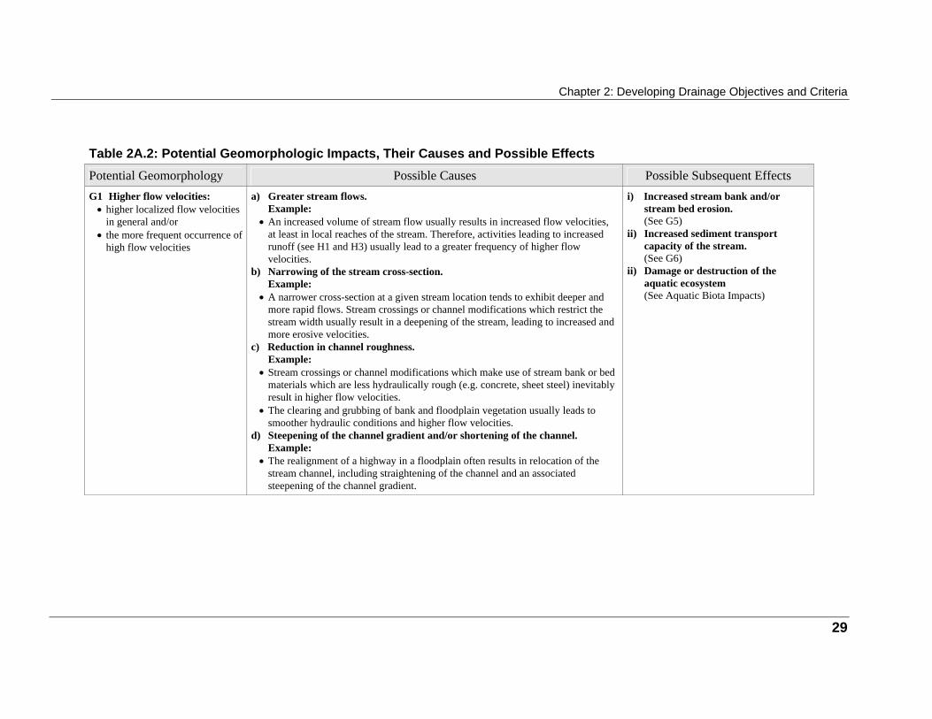
Chapter 2: Developing Drainage Objectives and Criteria
Table 2A.2: Potential Geomorphologic Impacts, Their Causes and Possible Effects
Potential Geomorphology Possible Causes Possible Subsequent Effects G1 Higher flow velocities:
• higher localized flow velocities in general and/or
• the more frequent occurrence of high flow velocities
a) Greater stream flows.
Example: • An increased volume of stream flow usually results in increased flow velocities,
at least in local reaches of the stream. Therefore, activities leading to increased runoff (see H1 and H3) usually lead to a greater frequency of higher flow velocities.
b) Narrowing of the stream cross-section. Example:
• A narrower cross-section at a given stream location tends to exhibit deeper and more rapid flows. Stream crossings or channel modifications which restrict the stream width usually result in a deepening of the stream, leading to increased and more erosive velocities.
c) Reduction in channel roughness. Example:
• Stream crossings or channel modifications which make use of stream bank or bed materials which are less hydraulically rough (e.g. concrete, sheet steel) inevitably result in higher flow velocities.
• The clearing and grubbing of bank and floodplain vegetation usually leads to smoother hydraulic conditions and higher flow velocities.
d) Steepening of the channel gradient and/or shortening of the channel. Example:
• The realignment of a highway in a floodplain often results in relocation of the stream channel, including straightening of the channel and an associated steepening of the channel gradient.
i) Increased stream bank and/or
stream bed erosion. (See G5)
ii) Increased sediment transport capacity of the stream. (See G6)
ii) Damage or destruction of the aquatic ecosystem (See Aquatic Biota Impacts)
29
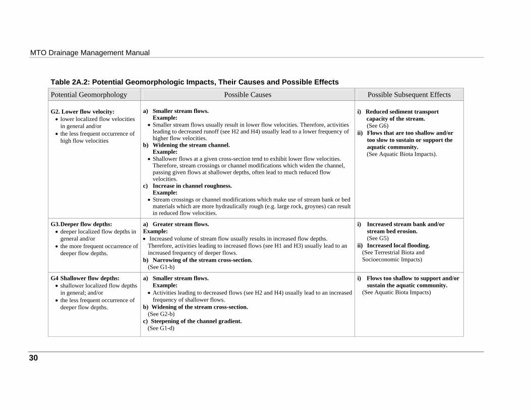
MTO Drainage Management Manual
Table 2A.2: Potential Geomorphologic Impacts, Their Causes and Possible Effects
Potential Geomorphology Possible Causes Possible Subsequent Effects G2. Lower flow velocity:
• lower localized flow velocities in general and/or
• the less frequent occurrence of high flow velocities
a) Smaller stream flows.
Example: • Smaller stream flows usually result in lower flow velocities. Therefore, activities
leading to decreased runoff (see H2 and H4) usually lead to a lower frequency of higher flow velocities.
b) Widening the stream channel. Example:
• Shallower flows at a given cross-section tend to exhibit lower flow velocities. Therefore, stream crossings or channel modifications which widen the channel, passing given flows at shallower depths, often lead to much reduced flow velocities.
c) Increase in channel roughness. Example:
• Stream crossings or channel modifications which make use of stream bank or bed materials which are more hydraulically rough (e.g. large rock, groynes) can result in reduced flow velocities.
i) Reduced sediment transport capacity of the stream.
(See G6) ii) Flows that are too shallow and/or
too slow to sustain or support the aquatic community.
(See Aquatic Biota Impacts).
G3. Deeper flow depths:
• deeper localized flow depths in general and/or
• the more frequent occurrence of deeper flow depths.
a) Greater stream flows. Example: • Increased volume of stream flow usually results in increased flow depths.
Therefore, activities leading to increased flows (see H1 and H3) usually lead to an increased frequency of deeper flows.
b) Narrowing of the stream cross-section. (See G1-b)
i) Increased stream bank and/or
stream bed erosion. (See G5)
ii) Increased local flooding. (See Terrestrial Biota and Socioeconomic Impacts)
G4 Shallower flow depths:
• shallower localized flow depths in general; and/or
• the less frequent occurrence of deeper flow depths.
a) Smaller stream flows.
Example: • Activities leading to decreased flows (see H2 and H4) usually lead to an increased
frequency of shallower flows. b) Widening of the stream cross-section.
(See G2-b) c) Steepening of the channel gradient. (See G1-d)
i) Flows too shallow to support and/or
sustain the aquatic community. (See Aquatic Biota Impacts)
30
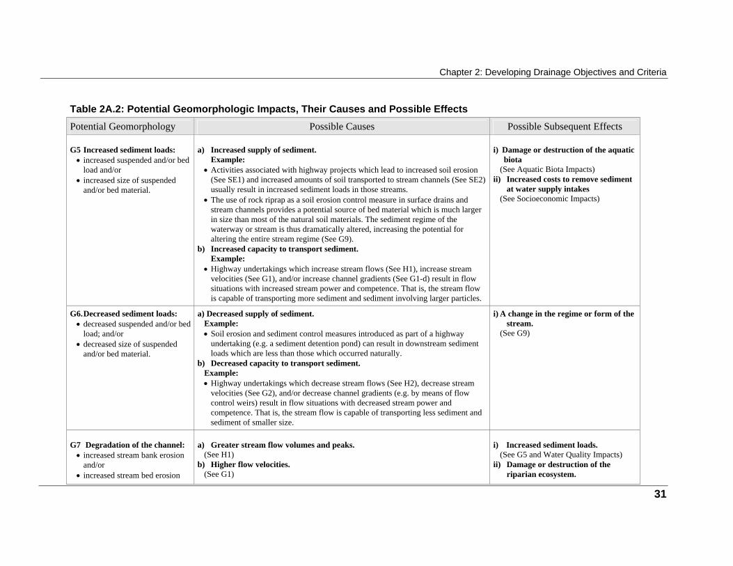
Chapter 2: Developing Drainage Objectives and Criteria
Table 2A.2: Potential Geomorphologic Impacts, Their Causes and Possible Effects
Potential Geomorphology Possible Causes Possible Subsequent Effects G5 Increased sediment loads:
• increased suspended and/or bed load and/or
• increased size of suspended and/or bed material.
a) Increased supply of sediment.
Example: • Activities associated with highway projects which lead to increased soil erosion
(See SE1) and increased amounts of soil transported to stream channels (See SE2) usually result in increased sediment loads in those streams.
• The use of rock riprap as a soil erosion control measure in surface drains and stream channels provides a potential source of bed material which is much larger in size than most of the natural soil materials. The sediment regime of the waterway or stream is thus dramatically altered, increasing the potential for altering the entire stream regime (See G9).
b) Increased capacity to transport sediment. Example:
• Highway undertakings which increase stream flows (See H1), increase stream velocities (See G1), and/or increase channel gradients (See G1-d) result in flow situations with increased stream power and competence. That is, the stream flow is capable of transporting more sediment and sediment involving larger particles.
i) Damage or destruction of the aquatic biota
(See Aquatic Biota Impacts) ii) Increased costs to remove sediment
at water supply intakes (See Socioeconomic Impacts)
G6. Decreased sediment loads:
• decreased suspended and/or bed load; and/or
• decreased size of suspended and/or bed material.
a) Decreased supply of sediment.
Example: • Soil erosion and sediment control measures introduced as part of a highway
undertaking (e.g. a sediment detention pond) can result in downstream sediment loads which are less than those which occurred naturally.
b) Decreased capacity to transport sediment. Example: • Highway undertakings which decrease stream flows (See H2), decrease stream
velocities (See G2), and/or decrease channel gradients (e.g. by means of flow control weirs) result in flow situations with decreased stream power and competence. That is, the stream flow is capable of transporting less sediment and sediment of smaller size.
i) A change in the regime or form of the
stream. (See G9)
G7 Degradation of the channel:
• increased stream bank erosion and/or
• increased stream bed erosion
a) Greater stream flow volumes and peaks.
(See H1) b) Higher flow velocities.
(See G1)
i) Increased sediment loads.
(See G5 and Water Quality Impacts) ii) Damage or destruction of the
riparian ecosystem.
31

MTO Drainage Management Manual
Table 2A.2: Potential Geomorphologic Impacts, Their Causes and Possible Effects
Potential Geomorphology Possible Causes Possible Subsequent Effects c) Deeper flow depths.
(See G3) (See Terrestrial Biota Impacts)
iii) Damage or destruction of the aquatic ecosystem.
(See Aquatic Biota Impacts) iv) Loss of property and/or facilities
(See Socioeconomic Impacts) G8 Aggradation of the channel:
• decreased stream bank erosion • decreased stream bed erosion • deposition of sediments
a) Lesser stream flow volumes and peaks.
(See H2) b) Lower flow velocities.
(See G2) c) Shallower flows.
(See G4)
i) Decreased sediment loads.
(See G6 and Water Quality Impacts) ii) Damage or destruction of the
aquatic ecosystem. (See Aquatic Biota Impacts)
G9. A change in the regime or
form of the stream: • the width: depth ratio of the
cross-section and/or its rate of change
• the sinuosity or meander pattern of the stream and/or its rate of change
• the bed form(s), e.g. riffles, pools, dunes, and/or their rates of change
a) A change in the flow regime.
Example: • Highway undertakings which lead to a change in the flow regime of the stream,
involving one or more of the items identified in H1 and H2, can lead to changes in the stream hydraulics and result in alterations in the fundamental geomorphology of the stream.
b) A change in the sediment regime. Example: • Just as in a) above, highway undertakings which lead to a change in the sediment
regime of the stream (See G5, 6, 7 and 8) can also lead to changes in the fundamental geomorphology of the stream.
i) A change in sediment loads.
(See G5, G6 and Water Quality Impacts)
ii) Loss of or damage to riparian and/or floodplain ecosystems.
(See Terrestrial Biota) iii) Loss of or damage to riparian
and/or floodplain lands and/or facilities
(See Socioeconomic Impacts)
32
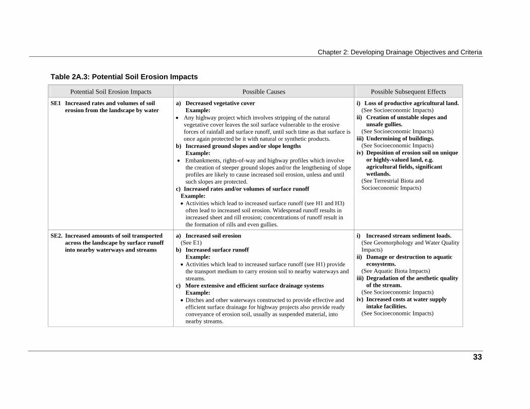
Chapter 2: Developing Drainage Objectives and Criteria
Table 2A.3: Potential Soil Erosion Impacts
Potential Soil Erosion Impacts Possible Causes Possible Subsequent Effects SE1 Increased rates and volumes of soil
erosion from the landscape by water
a) Decreased vegetative cover
Example: • Any highway project which involves stripping of the natural
vegetative cover leaves the soil surface vulnerable to the erosive forces of rainfall and surface runoff, until such time as that surface is once again protected be it with natural or synthetic products.
b) Increased ground slopes and/or slope lengths Example:
• Embankments, rights-of-way and highway profiles which involve the creation of steeper ground slopes and/or the lengthening of slope profiles are likely to cause increased soil erosion, unless and until such slopes are protected.
c) Increased rates and/or volumes of surface runoff Example: • Activities which lead to increased surface runoff (see H1 and H3)
often lead to increased soil erosion. Widespread runoff results in increased sheet and rill erosion; concentrations of runoff result in the formation of rills and even gullies.
i) Loss of productive agricultural land.
(See Socioeconomic Impacts) ii) Creation of unstable slopes and
unsafe gullies. (See Socioeconomic Impacts)
iii) Undermining of buildings. (See Socioeconomic Impacts)
iv) Deposition of erosion soil on unique or highly-valued land, e.g. agricultural fields, significant wetlands.
(See Terrestrial Biota and Socioeconomic Impacts)
SE2. Increased amounts of soil transported
across the landscape by surface runoff into nearby waterways and streams
a) Increased soil erosion
(See E1) b) Increased surface runoff
Example: • Activities which lead to increased surface runoff (see H1) provide
the transport medium to carry erosion soil to nearby waterways and streams.
c) More extensive and efficient surface drainage systems Example:
• Ditches and other waterways constructed to provide effective and efficient surface drainage for highway projects also provide ready conveyance of erosion soil, usually as suspended material, into nearby streams.
i) Increased stream sediment loads.
(See Geomorphology and Water Quality Impacts)
ii) Damage or destruction to aquatic ecosystems.
(See Aquatic Biota Impacts) iii) Degradation of the aesthetic quality
of the stream. (See Socioeconomic Impacts)
iv) Increased costs at water supply intake facilities.
(See Socioeconomic Impacts)
33

MTO Drainage Management Manual
Table 2A.4: Potential Water Quality Impacts, Their Causes and Possible Effects
Potential Water Quality Impacts Possible Causes Possible Subsequent Effects WQ1 Changes in the water chemistry of
streams and wetlands brought about by new inputs of materials:
• toxic chemicals • nutrients • salts
a) Losses of material from vehicles.
Example: • The introduction of a highway into an area or the expansion of an
existing highway system results in losses and increased losses of oil/grease, trace organics, trace metals and nutrients from vehicles and vehicle exhausts.
• The upgrading of highway systems often results in an increase in the incidence of chemical spills resulting from accidents and of illegal dumping of liquid or solid material (contaminated water may be leached from solid material through the accumulation of precipitation, e.g. mounds of asphalt).
b) Road Maintenance Procedures Example:
• Road salting, sanding and road maintenance practices on highways increase the chance of chemicals getting into the adjacent water systems.
• Use of pesticides to control roadside vegetation often alters the water chemistry of adjacent streams and wetlands.
• There can be movement of materials such as salt from storage sites to local drainage systems.
i) Changes in animal or plant species or
communities (See Aquatic Biota Impacts)
ii) Contamination of groundwater used for drinking water and the maintenance of base flow in streams
(See Socioeconomic Impacts) iii) Increased requirements for
municipal, industrial or agricultural users of surface or ground water supplies for water treatment
(See Socioeconomic Impacts) iv) Increases in nutrient loads to
downstream aquatic ecosystems (See WQ2)
v) Contamination of aquatic or surface sediments
(See WQ3)
34
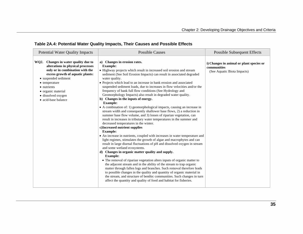
Chapter 2: Developing Drainage Objectives and Criteria
Table 2A.4: Potential Water Quality Impacts, Their Causes and Possible Effects
Potential Water Quality Impacts Possible Causes Possible Subsequent Effects WQ2. Changes in water quality due to
alterations in physical processes only or in combination with the excess growth of aquatic plants:
• suspended sediment • temperature • nutrients • organic material • dissolved oxygen • acid-base balance
a) Changes in erosion rates.
Example: • Highway projects which result in increased soil erosion and stream
sediment (See Soil Erosion Impacts) can result in associated degraded water quality.
• Projects which lead to an increase in bank erosion and associated suspended sediment loads, due to increases in flow velocities and/or the frequency of bank full flow conditions (See Hydrology and Geomorphology Impacts) also result in degraded water quality.
b) Changes in the inputs of energy. Example:
• A combination of: 1) geomorphological impacts, causing an increase in stream width and consequently shallower base flows, 2) a reduction in summer base flow volume, and 3) losses of riparian vegetation, can result in increases in tributary water temperatures in the summer and decreased temperatures in the winter.
c) Increased nutrient supplies Example:
• An increase in nutrients, coupled with increases in water temperature and light regimes, stimulates the growth of algae and macrophytes and can result in large diurnal fluctuations of pH and dissolved oxygen in stream and some wetland ecosystems.
d) Changes in organic matter quality and supply. Example:
• The removal of riparian vegetation alters inputs of organic matter to the adjacent stream and in the ability of the stream to trap organic matter through fallen logs and branches. Such removal therefore leads to possible changes in the quality and quantity of organic material in the stream, and structure of benthic communities. Such changes in turn affect the quantity and quality of food and habitat for fisheries.
i) Changes in animal or plant species or communities
(See Aquatic Biota Impacts)
35

MTO Drainage Management Manual
Table 2A.4: Potential Water Quality Impacts, Their Causes and Possible Effects
Potential Water Quality Impacts Possible Causes Possible Subsequent Effects WQ3. Changes in aquatic and surface sediment quality
a) Contaminated Stormwater.
Example: • Contamination of suspended sediment with trace metals and/or trace
organics found in stormwater can result in aquatic sediments or surface sediments which are hazardous to biota.
i) Losses or reductions in animal or plant species or communities
(See Aquatic Biota Impacts) ii) Disruptions in animal behaviour
(See Aquatic Biota Impacts) iii) Restrictions on downstream dredging
(See Socioeconomic Impacts)
WQ4. Localized contamination of air,
dry deposition, or wet deposition
a) Pollutants associated with vehicle exhaust or construction and
maintenance activities Example:
• Wet or dry deposition of salty, oily or dusty material from highways onto nearby native plant communities, tree plantations or agricultural crops can cause significant damage.
• Drift of pesticides used for roadside vegetative control can damage or destroy non-target plants or insects. The loss of pollinating insects, due to non-target impacts of pesticide use, can also affect some agricultural crops.
i) Loss of plant species or communities
(See Impacts on Terrestrial Biota or Aquatic Biota)
ii) Contamination or loss of agricultural crops (See Socioeconomic Impacts)
iii) Contamination of aquatic or surface sediments (See WQ3)
36
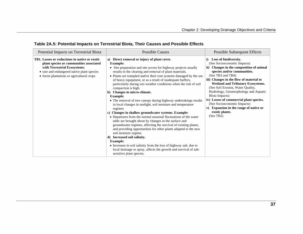
Chapter 2: Developing Drainage Objectives and Criteria
Table 2A.5: Potential Impacts on Terrestrial Biota, Their Causes and Possible Effects
Potential Impacts on Terrestrial Biota Possible Causes Possible Subsequent Effects TB1. Losses or reductions in native or exotic
plant species or communities associated with Terrestrial Ecosystems:
• rare and endangered native plant species • forest plantations or agricultural crops
a) Direct removal or injury of plant cover.
Example: • Site preparation and site access for highway projects usually
results in the clearing and removal of plant materials. • Plants are trampled and/or their root systems damaged by the use
of heavy equipment, or as a result of inadequate buffers, particularly during wet weather conditions when the risk of soil compaction is high.
b) Changes in micro-climate. Example:
• The removal of tree canopy during highway undertakings results in local changes in sunlight, soil moisture and temperature regimes
c) Changes in shallow groundwater systems. Example: • Departures from the normal seasonal fluctuations of the water
table are brought about by changes in the surface and groundwater regimes, affecting the survival of existing plants, and providing opportunities for other plants adapted to the new soil moisture regime.
d) Increased soil salinity. Example: • Increases in soil salinity from the loss of highway salt, due to
local drainage or spray, affects the growth and survival of salt-sensitive plant species.
i) Loss of biodiversity.
(See Socioeconomic Impacts) ii) Changes in the composition of animal
species and/or communities. (See TB3 and TB4)
iii) Changes in the flow of material to Wetland and Tributary Ecosystems.
(See Soil Erosion, Water Quality, Hydrology, Geomorphology and Aquatic Biota Impacts)
iv) Losses of commercial plant species. (See Socioeconomic Impacts)
v) Expansion in the range of native or exotic plants.
(See TB2)
37
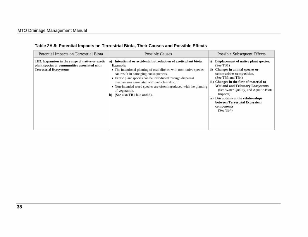
MTO Drainage Management Manual
Table 2A.5: Potential Impacts on Terrestrial Biota, Their Causes and Possible Effects
Potential Impacts on Terrestrial Biota Possible Causes Possible Subsequent Effects TB2. Expansion in the range of native or exotic plant species or communities associated with Terrestrial Ecosystems
a) Intentional or accidental introduction of exotic plant biota.
Example: • The intentional planting of road ditches with non-native species
can result in damaging consequences. • Exotic plant species can be introduced through dispersal
mechanisms associated with vehicle traffic. • Non-intended weed species are often introduced with the planting
of vegetation. b) (See also TB1 b, c and d).
i) Displacement of native plant species.
(See TB1) ii) Changes in animal species or
communities composition. (See TB3 and TB4)
iii) Changes in the flow of material to Wetland and Tributary Ecosystems
(See Water Quality, and Aquatic Biota Impacts)
iv) Disruptions in the relationships between Terrestrial Ecosystem components
(See TB4)
38
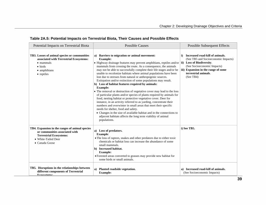
Chapter 2: Developing Drainage Objectives and Criteria
Table 2A.5: Potential Impacts on Terrestrial Biota, Their Causes and Possible Effects
Potential Impacts on Terrestrial Biota Possible Causes Possible Subsequent Effects TB3. Losses of animal species or communities
associated with Terrestrial Ecosystems: • mammals • birds • amphibians • reptiles
a) Barriers to migration or animal movement:
Example: • Highway drainage features may prevent amphibians, reptiles and/or
mammals from crossing the route. As a consequence, the animals may not be able to successfully complete their life stages and/or be unable to recolonize habitats where animal populations have been lost due to stresses from natural or anthropogenic sources. Extirpation and/or extinction of some populations may result.
b) Loss of habitat features required by animals: Example: • The removal or destruction of vegetative cover may lead to the loss
of particular plants and/or species of plants required by animals for food, nesting habitat or protective vegetative cover. Deer for instance, in an activity referred to as yarding, concentrate their numbers and overwinter in small areas that meet their specific needs for shelter, food and safety. • Changes in the size of available habitat and in the connections to
adjacent habitats affects the long term viability of animal populations.
i) Increased road-kill of animals.
(See TB5 and Socioeconomic Impacts) ii) Loss of Biodiversity.
(See Socioeconomic Impacts) iii) Expansion in the range of some
terrestrial animals. (See TB4)
TB4. Expansion in the ranges of animal species
or communities associated with Terrestrial Ecosystems:
• White-Tailed Deer • Canada Goose
a) Loss of predators.
Example: • The loss of raptors, snakes and other predators due to either toxic
chemicals or habitat loss can increase the abundance of some small mammals.
b) Increased habitat. Example:
• Forested areas converted to grasses may provide new habitat for some birds or small animals.
i) See TB5.
TB5. Disruptions in the relationships between
different components of Terrestrial Ecosystems:
a) Planted roadside vegetation.
Example:
a) Increased road-kill of animals.
(See Socioeconomic Impacts)
39
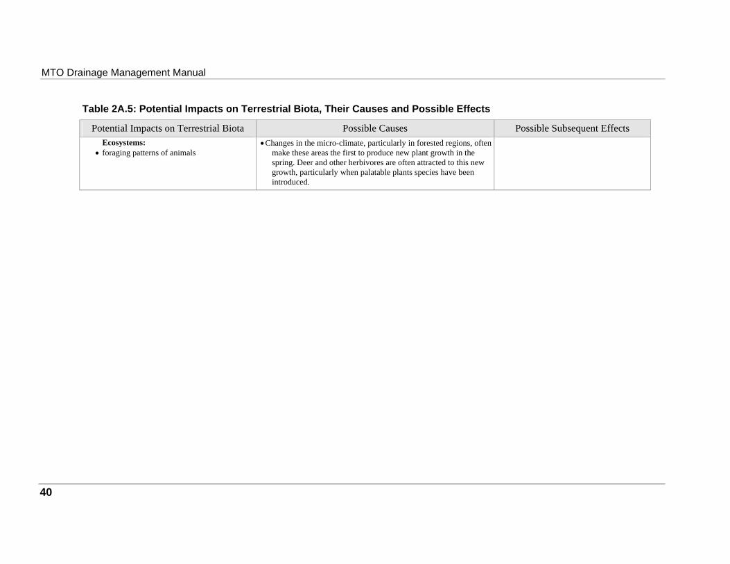
MTO Drainage Management Manual
Table 2A.5: Potential Impacts on Terrestrial Biota, Their Causes and Possible Effects
Potential Impacts on Terrestrial Biota Possible Causes Possible Subsequent Effects Ecosystems:
• foraging patterns of animals
• Changes in the micro-climate, particularly in forested regions, often make these areas the first to produce new plant growth in the spring. Deer and other herbivores are often attracted to this new growth, particularly when palatable plants species have been introduced.
40
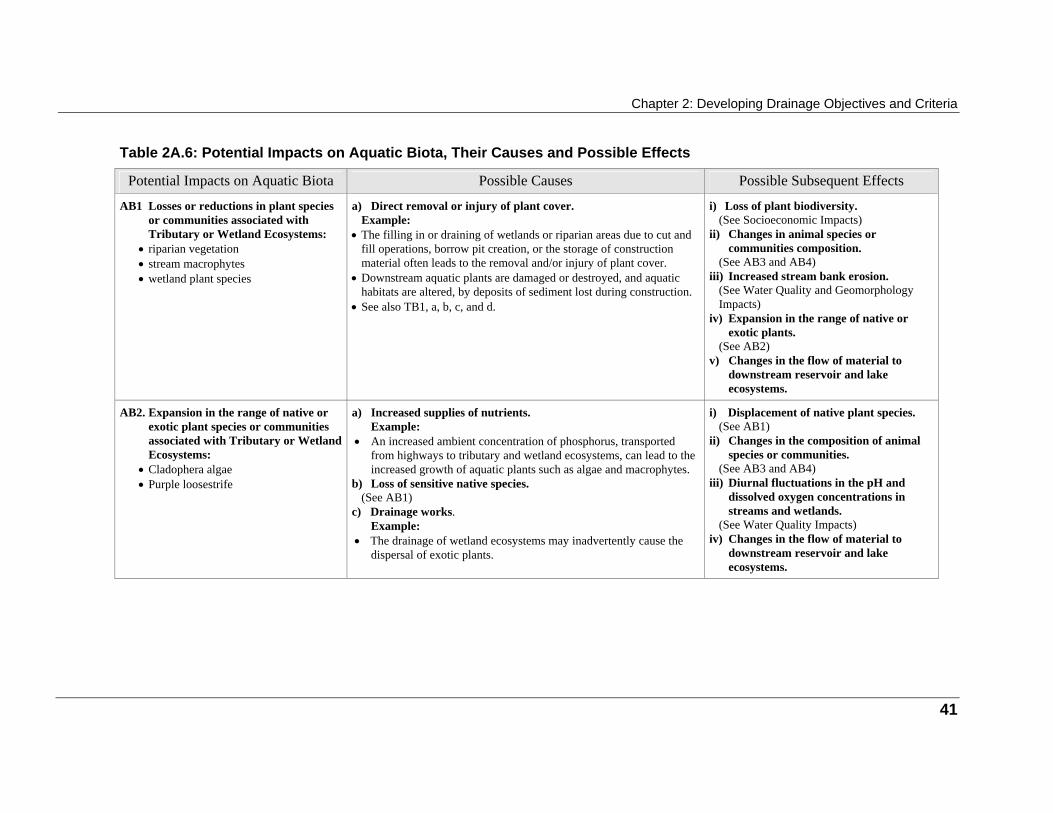
Chapter 2: Developing Drainage Objectives and Criteria
Table 2A.6: Potential Impacts on Aquatic Biota, Their Causes and Possible Effects
Potential Impacts on Aquatic Biota Possible Causes Possible Subsequent Effects AB1 Losses or reductions in plant species
or communities associated with Tributary or Wetland Ecosystems:
• riparian vegetation • stream macrophytes • wetland plant species
a) Direct removal or injury of plant cover.
Example: • The filling in or draining of wetlands or riparian areas due to cut and
fill operations, borrow pit creation, or the storage of construction material often leads to the removal and/or injury of plant cover.
• Downstream aquatic plants are damaged or destroyed, and aquatic habitats are altered, by deposits of sediment lost during construction.
• See also TB1, a, b, c, and d.
i) Loss of plant biodiversity.
(See Socioeconomic Impacts) ii) Changes in animal species or
communities composition. (See AB3 and AB4)
iii) Increased stream bank erosion. (See Water Quality and Geomorphology Impacts)
iv) Expansion in the range of native or exotic plants.
(See AB2) v) Changes in the flow of material to
downstream reservoir and lake ecosystems.
AB2. Expansion in the range of native or
exotic plant species or communities associated with Tributary or Wetland Ecosystems:
• Cladophera algae • Purple loosestrife
a) Increased supplies of nutrients.
Example: • An increased ambient concentration of phosphorus, transported
from highways to tributary and wetland ecosystems, can lead to the increased growth of aquatic plants such as algae and macrophytes.
b) Loss of sensitive native species. (See AB1)
c) Drainage works. Example:
• The drainage of wetland ecosystems may inadvertently cause the dispersal of exotic plants.
i) Displacement of native plant species.
(See AB1) ii) Changes in the composition of animal
species or communities. (See AB3 and AB4)
iii) Diurnal fluctuations in the pH and dissolved oxygen concentrations in streams and wetlands.
(See Water Quality Impacts) iv) Changes in the flow of material to
downstream reservoir and lake ecosystems.
41
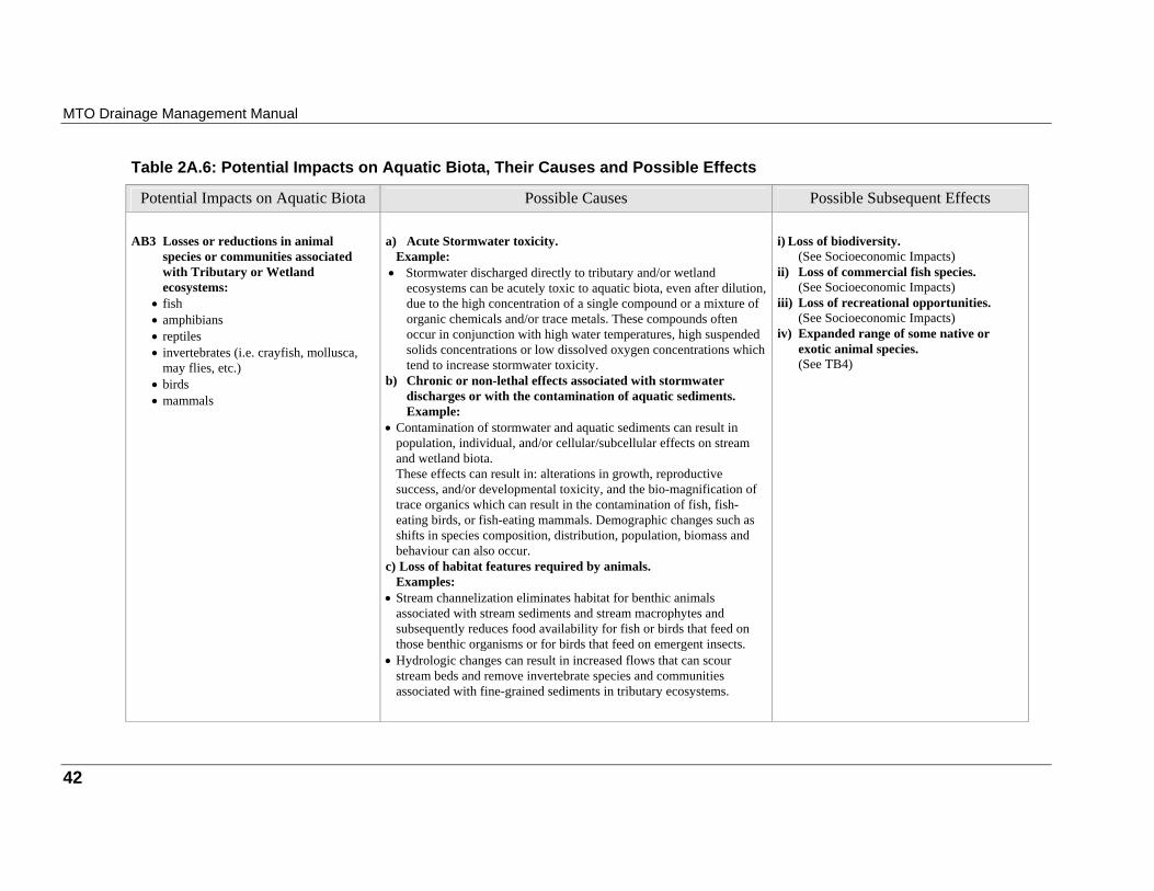
MTO Drainage Management Manual
Table 2A.6: Potential Impacts on Aquatic Biota, Their Causes and Possible Effects
Potential Impacts on Aquatic Biota Possible Causes Possible Subsequent Effects AB3 Losses or reductions in animal
species or communities associated with Tributary or Wetland ecosystems:
• fish • amphibians • reptiles • invertebrates (i.e. crayfish, mollusca,
may flies, etc.) • birds • mammals
a) Acute Stormwater toxicity.
Example: • Stormwater discharged directly to tributary and/or wetland
ecosystems can be acutely toxic to aquatic biota, even after dilution, due to the high concentration of a single compound or a mixture of organic chemicals and/or trace metals. These compounds often occur in conjunction with high water temperatures, high suspended solids concentrations or low dissolved oxygen concentrations which tend to increase stormwater toxicity.
b) Chronic or non-lethal effects associated with stormwater discharges or with the contamination of aquatic sediments. Example:
• Contamination of stormwater and aquatic sediments can result in population, individual, and/or cellular/subcellular effects on stream and wetland biota. These effects can result in: alterations in growth, reproductive success, and/or developmental toxicity, and the bio-magnification of trace organics which can result in the contamination of fish, fish-eating birds, or fish-eating mammals. Demographic changes such as shifts in species composition, distribution, population, biomass and behaviour can also occur.
c) Loss of habitat features required by animals. Examples:
• Stream channelization eliminates habitat for benthic animals associated with stream sediments and stream macrophytes and subsequently reduces food availability for fish or birds that feed on those benthic organisms or for birds that feed on emergent insects.
• Hydrologic changes can result in increased flows that can scour stream beds and remove invertebrate species and communities associated with fine-grained sediments in tributary ecosystems.
i) Loss of biodiversity.
(See Socioeconomic Impacts) ii) Loss of commercial fish species.
(See Socioeconomic Impacts) iii) Loss of recreational opportunities.
(See Socioeconomic Impacts) iv) Expanded range of some native or
exotic animal species. (See TB4)
42

Chapter 2: Developing Drainage Objectives and Criteria
Table 2A.6: Potential Impacts on Aquatic Biota, Their Causes and Possible Effects
Potential Impacts on Aquatic Biota Possible Causes Possible Subsequent Effects
• Changes in stream geomorphology that result in high flow velocities can prevent the upstream migration of fish or other aquatic biota leaving this stream habitat under utilized and reducing the range and resilience of effected animal species and communities.
• Low velocities in combination with shallow flows due to stream widening and base flow reductions can have a similar effect by reducing the ability of aquatic biota to migrate or to escape stresses such as high water temperatures.
• Disruptions in nutrient cycling (i.e. phosphorus, nitrogen, carbon, trace nutrients) and decomposition rates can either increase or decrease the food supply for animals.
• Removal of riparian vegetation can change stream water temperature and light regimes. Such alterations can change in-stream primary productivity, provided the nutrients are available, by stimulating the growth of algae. Stream biota which cannot adapt to the increases in water temperatures or habitat changes will be replaced by more tolerant native or exotic species.
AB4. Expansion in the range of animal
species associated with Wetland or Tributary Ecosystems:
• fish
a) Degraded habitat.
Example: • Reductions in the quality of existing habitat provide opportunities for
more tolerant fish species.
i) Loss of animal biodiversity
(See Socioeconomic Impacts)
43
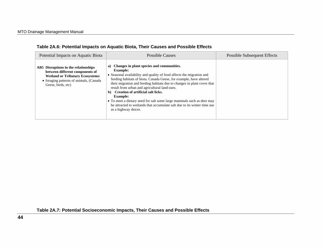
MTO Drainage Management Manual
Table 2A.6: Potential Impacts on Aquatic Biota, Their Causes and Possible Effects
Potential Impacts on Aquatic Biota Possible Causes Possible Subsequent Effects AB5 Disruptions in the relationships
between different components of Wetland or Tributary Ecosystems:
• foraging patterns of animals, (Canada Geese, birds, etc)
a) Changes in plant species and communities.
Example: • Seasonal availability and quality of food affects the migration and
feeding habitats of biota. Canada Geese, for example, have altered their migration and feeding habitats due to changes in plant cover that result from urban and agricultural land-uses.
b) Creation of artificial salt licks. Example:
• To meet a dietary need for salt some large mammals such as deer may be attracted to wetlands that accumulate salt due to its winter time use as a highway deicer.
Table 2A.7: Potential Socioeconomic Impacts, Their Causes and Possible Effects 44
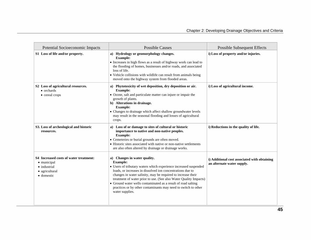
Chapter 2: Developing Drainage Objectives and Criteria
Potential Socioeconomic Impacts
Possible Causes
Possible Subsequent Effects
S1 Loss of life and/or property.
a) Hydrology or geomorphology changes.
Example: • Increases in high flows as a result of highway work can lead to
the flooding of homes, businesses and/or roads, and associated loss of life.
• Vehicle collisions with wildlife can result from animals being moved onto the highway system from flooded areas.
i) Loss of property and/or injuries.
S2 Loss of agricultural resources.
• orchards • cereal crops
a) Phytotoxicity of wet deposition, dry deposition or air.
Example: • Ozone, salt and particulate matter can injure or impair the
growth of plants. b) Alterations in drainage.
Example: • Changes to drainage which affect shallow groundwater levels
may result in the seasonal flooding and losses of agricultural crops.
i) Loss of agricultural income.
S3. Loss of archeological and historic
resources.
a) Loss of or damage to sites of cultural or historic
importance to native and non-native peoples. Example:
• Cemeteries or burial grounds are often moved. • Historic sites associated with native or non-native settlements
are also often altered by drainage or drainage works.
i) Reductions in the quality of life.
S4 Increased costs of water treatment:
• municipal • industrial • agricultural • domestic
a) Changes in water quality.
Example: • Users of tributary waters which experience increased suspended
loads, or increases in dissolved ion concentrations due to changes in water salinity, may be required to increase their treatment of water prior to use. (See also Water Quality Impacts)
• Ground water wells contaminated as a result of road salting practices or by other contaminants may need to switch to other water supplies.
i) Additional cost associated with obtaining an alternate water supply.
45
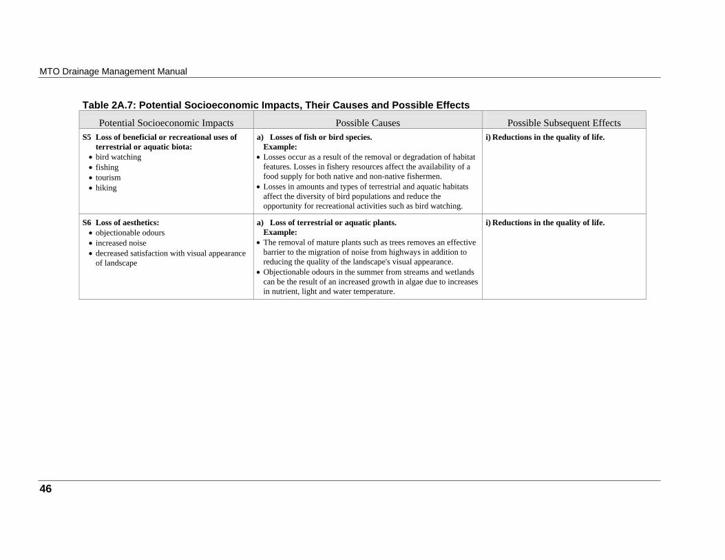
MTO Drainage Management Manual
Table 2A.7: Potential Socioeconomic Impacts, Their Causes and Possible Effects
Potential Socioeconomic Impacts
Possible Causes
Possible Subsequent Effects S5 Loss of beneficial or recreational uses of
terrestrial or aquatic biota: • bird watching • fishing • tourism • hiking
a) Losses of fish or bird species.
Example: • Losses occur as a result of the removal or degradation of habitat
features. Losses in fishery resources affect the availability of a food supply for both native and non-native fishermen.
• Losses in amounts and types of terrestrial and aquatic habitats affect the diversity of bird populations and reduce the opportunity for recreational activities such as bird watching.
i) Reductions in the quality of life.
S6 Loss of aesthetics:
• objectionable odours • increased noise • decreased satisfaction with visual appearance
of landscape
a) Loss of terrestrial or aquatic plants.
Example: • The removal of mature plants such as trees removes an effective
barrier to the migration of noise from highways in addition to reducing the quality of the landscape's visual appearance.
• Objectionable odours in the summer from streams and wetlands can be the result of an increased growth in algae due to increases in nutrient, light and water temperature.
i) Reductions in the quality of life.
46
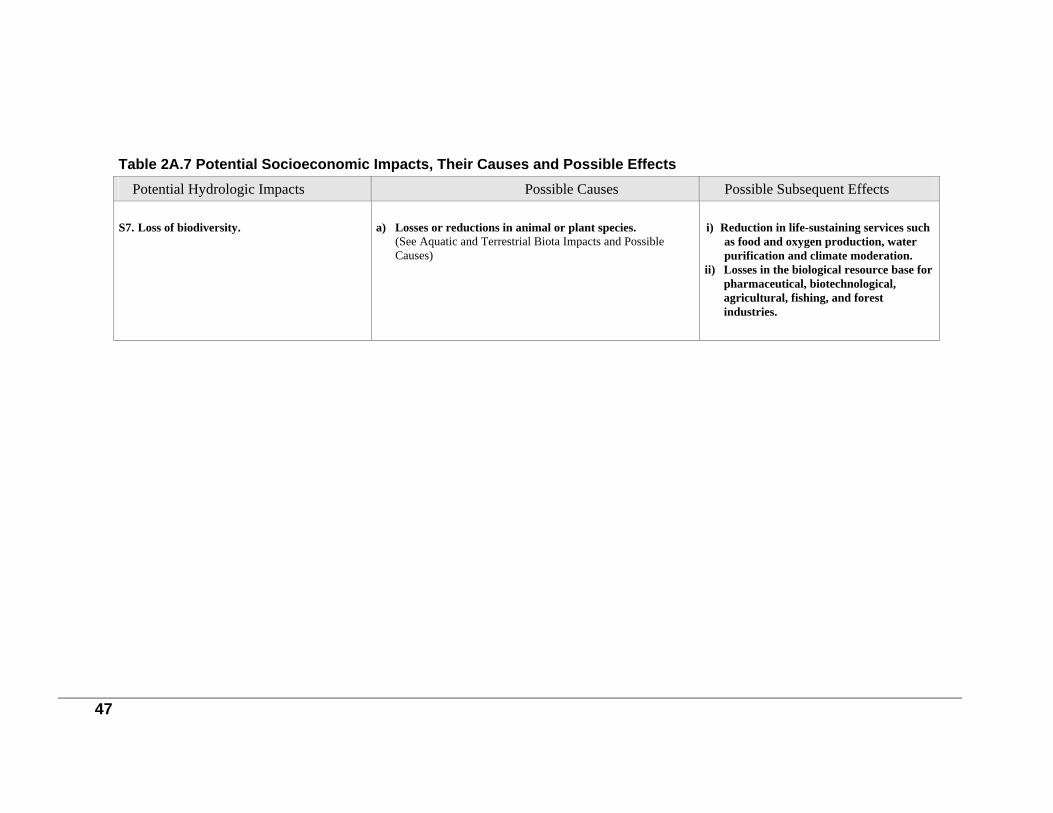
Table 2A.7 Potential Socioeconomic Impacts, Their Causes and Possible Effects Potential Hydrologic Impacts
Possible Causes
Possible Subsequent Effects
S7. Loss of biodiversity.
a) Losses or reductions in animal or plant species.
(See Aquatic and Terrestrial Biota Impacts and Possible Causes)
i) Reduction in life-sustaining services such
as food and oxygen production, water purification and climate moderation.
ii) Losses in the biological resource base for pharmaceutical, biotechnological, agricultural, fishing, and forest industries.
47
48
Appendix 2B: Common Law Principles
Note: Appendix 2B is intended to provide information and guidance on the more important legal aspects of highway drainage. For instance, the practitioner needs to have sufficient knowledge of drainage law to be able to recognize and avoid potential legal problems, such as those commonly caused by flow diversions, concentration of flow, obstruction of flows by bridges or culverts, and stream bank erosion. This appendix should not be used as a substitute for legal counsel. Since the legal aspects of highway drainage can be confusing and complex, the advice of MTO legal counsel should be obtained for drainage matters, as necessary.
Natural Watercourses Almost all the laws governing natural watercourses are founded on the maxim Aqua currit et debet currere, i.e. water flows naturally and should be permitted thus to flow1.
The Courts have said, that to constitute a natural watercourse, the channel bank formed by the flowing of water must present to the eye on casual examination the unmistakable evidence of the frequent action of running water. On another occasion that a watercourse is constituted if there is sufficient natural and accustomed flow of water to form and maintain a distinct and defined channel. It is not essential that the supply should be continuous or form a perennial living source. It is enough if the water rises periodically and reaches a fairly defined channel of permanent character. A natural watercourse does not cease to be such if at a certain point it spreads out over a level area and flows for a distance without defined banks before flowing again in a defined channel. Often it is the valley through which the stream runs, and not its low level or low water channel, which is the watercourse2.
Riparian Rights and Obligations A riparian owner is one whose land is in actual contact with a natural watercourse. As such, he has the unique right to drain that land into the watercourse. Where a highway crosses a natural watercourse, the Crown, as owner of the land, acquires riparian rights, and may therefore drain the highway into the watercourse.
1Common Law Aspects of Water by R.A.W. Irwin and published by Ontario Ministry of Agriculture, Food and Rural Affairs, 1974. 2Drainage Law by A.B. McIlmoyle and published by The Municipal World, April 1969.
Chapter 2: Developing Drainage Objectives and Criteria
49
A riparian owner is not only entitled to have water in a natural watercourse flow to his land in its natural state as a benefit, but is also obliged to receive it even if it becomes a nuisance due to flooding, erosion or other reasons. However, the strict rights of riparian owners are tempered by obligations under drainage law and nuisance law; and, the obligation to ensure a sufficient outlet may have more legal force than the riparian owner’s property based right to drain his/her land into the watercourses. On the other hand, persons not riparian owners who obtain an outlet to the stream are liable to a downstream riparian owner whose land is damaged by the increased amount of water. It should also be noted that statutory rights of outlet, such as those under the Drainage Act, in no way interferes with the common law rights of a riparian owner. Reasonable use of a stream has been defined as a use up to the capacity of the banks of the stream. Determination of the "banks" depends upon the water level selected and has not been explicitly defined in law. The natural banks may be delineated by normal summer flow, an average annual flood having approximately a 2.3 year return period, or a higher flow caused by more severe flood conditions, spring tides or other natural phenomena. In instances of dispute, legal action may be necessary to establish the location of natural banks. The right to discharge water into a natural watercourse is subject to certain restrictions. • The riparian owner may not bring in water which has not fallen within the natural
watershed. In other words, water from one watershed may not be diverted into another. • The owner may not assign or sell his/her rights to drain into that watercourse. In
essence, this means that to secure riparian rights one must obtain ownership of the land itself. The common law has been modified by s.27 of the Ontario Water Resources Act which provides that A right or interest in, over, above, upon, across, along, through, under or affecting any land ... in respect of water or sewage works may be granted to either the Crown or a municipality not withstanding that the right is not appurtenant or annexed to any land of the Crown or municipality. Accordingly, the right to drain into a watercourse may be granted to the Crown or a municipality. However, it is not clear if the full rights of a riparian owner can be transferred (even to the Crown or a municipality) unless the land itself is transferred.
• The right to discharge water into a natural watercourse is also subject to an implied proviso that the riparian owner must be making a “reasonable use” of his/her property.
Use of Water A riparian owner has the right to have the water flow to him/her in its natural state with regard to both quantity and quality, subject to certain qualifications, and may put the water from the natural watercourse to any reasonable use. This may include irrigation and the watering of livestock. Extraordinary use, such as for industrial purposes, would not be reasonable unless the water were returned to the natural watercourse before it left the user's land, substantially unaltered in quantity (i.e. less that which is absorbed) and quality.
MTO Drainage Management Manual
50
Section 34(3) of the Ontario Water Resources Act restricts the removal of water to 50,000 litres/day. For a greater amount, a permit is required from the Ministry of Environment and Energy (MOEE). Section 34(4) states that if the proposed uses interfere with domestic uses of another, the MOEE may prohibit the taking of such water. A contractor must adhere to both these sections.
Interference with Natural Watercourses There are many types of works that have been held by the courts to constitute interference with a natural watercourse; these include deepening and widening, removing silt or gravel deposits, channel straightening, the construction of bridges, culverts or stream diversions, and channel maintenance. It is important to remember that it is the duty of anyone who interferes with a natural watercourse to see that the works are adequate to carry the flow of water, even that resulting from an extraordinary rainfall. If not, he must accept all liability for his/her action and must prove his/her innocence. This is discussed further in the Watercourse Crossing section. When a natural watercourse becomes silted up or choked by vegetation, there is no liability or obligation upon the owner either to clear the channel or to compensate adjoining landowners for flood damage. However, if he takes it upon himself/herself to clean the channel, he/she is liable for any damage his/her interference may cause3. In such circumstances, it is recognized that MTO probably has a duty to clear up its culverts; and, this duty is part of the broader duty to maintain the highway in a good state of repair. In a case where a culvert has been clogged for a lengthy period of time, downstream owners may have developed their properties in such a way that the consequence of a culvert cleanup may be that such downstream owners experience flooding problems. In this situation, legal advice should normally be obtained prior to commencement of the cleanup, whenever practical.
Diversions A natural watercourse may be diverted by a landowner provided it is returned to its natural location within the same property. However, the riparian owner may be liable for damage due to the diversion, both upstream and downstream, whether or not his/her use of the stream is reasonable. This fact must be considered when MTO constructs diversions for bridge and culvert installations. Normally such diversions are undertaken by permit from the Ministry of Natural Resources (MNR) under the provisions of the Lakes and Rivers Improvement Act. The Act does not bind the MTO,
3Drainage and the Law by H. McDougall and published by Civic, March 1976.
Chapter 2: Developing Drainage Objectives and Criteria
51
but in practice MTO keeps MNR informed of all instances of major diversions, and solicits their comments. MTO, however, is bound by the Environmental Assessment Act, and is required to submit to the MOEE an environmental assessment report whenever a permanent environmentally significant watercourse diversion is proposed in lieu of bridges or culverts. Requirements under the Environmental Assessment Act are discussed further in the Statute Law section. As mentioned earlier, water may not be diverted from one watershed to another. The courts have held that work which directed water from point A to point C (instead of the natural direction from A to B) is in violation of common law, regardless of how minor the change in drainage pattern may be. Claims might be based on a diminution of flow between A and B, or on an increased flow between points A, C and B. In the upper reaches of a drainage basin each gentle undulation in the topography may define a distinct subwatershed in the eyes of the court. Where a highway traverses rugged terrain on alternating cuts and fills, diversions of minor amounts of water from one watershed to another may be justified if substantial cost savings can be achieved and if future claims or adverse environmental impacts are unlikely. In any case the affected municipality and conservation authority or Ontario Ministry of Natural Resources should be consulted regarding a change in drainage areas.
Watercourse Crossings Although common law requires that works substituted for a natural watercourse must accommodate a flow resulting from an extraordinary rainfall, the latter term has not yet been defined. In recognition of accepted engineering practice and economic realities, it is the policy of MTO to design most drainage facilities on the basis of pre-selected storm or flood frequencies. Road fills crossing natural watercourses may behave as dams and levees if they constrict the flood plain, thereby temporarily increasing flooding upstream. This may provide a basis for suit under common law when it can be shown that significant damage is caused.
Surface Flow The principles which apply to natural watercourses are different from those for surface flow (i.e. sheet flow), for which a separate and distinct set of common law rules governs the rights and obligations of owners.
Obstruction of Surface Flow An owner of land, which is at a lower elevation than a neighbouring land, has the right to either
allow water from higher land to flow over his/her land, or keep such water off his/her property by
MTO Drainage Management Manual
52
dams and banks. The owner should ensure that the dams or banks do not result in unreasonable interference with adjacent property owners’ enjoyment of his/her property.
Increase of Surface Flow An owner who paves the surface of his/her land and thereby increases the rate of surface runoff is not normally liable under common law, as long as the surfacing does not result in unreasonable interference with adjacent property owners’ right to enjoyment.
Collection of Surface Flow If a ditch, pipe or curb and gutter is constructed to collect surface water, it is then necessary to provide a sufficient outlet for the collected water, as no owner has the right to collect surface water in this fashion and discharge it onto the lands of others. Sufficient outlet is defined in Section 1(29) of the Drainage Act as a point at which water can be discharged safely so that it will do no damage to lands or roads. Although not judicially resolved in common law, for the purposes of MTO the definition may also be applied to situations other than those related to the Drainage Act. MTO should carry collected surface drainage to a sufficient outlet or employ some other solution, such as compensation, that is acceptable to all parties concerned.
Surface Flow and the MTO Where a roadway embankment intercepts surface flow, MTO is within its legal rights to allow that water to pond behind the embankment. However, if this is likely to cause an adverse environmental impact, such as crop damage, the Environmental Assessment Act would apply. If significant damage to upstream properties is likely, it is good policy to collect and carry this water to a sufficient outlet, even though MTO may not be liable for upstream damage. On the downstream side of the embankment the use of roadside ditches to intercept surface water should be minimized, unless there are circumstances that may cause undue inconvenience or hardship to the adjacent landowner.
Subsurface Flow
Underground Water in a Defined Channel Insofar as the rights and obligations of landowners are concerned, subterranean flowing streams that have definite courses may be treated for all practical purposes, as natural watercourses on the surface4. Thus an owner is entitled to put an underground stream to any reasonable use.
4Gale on Easements by S.G. Maurice and published by Sweet & Maxwell Ltd., London, England, 1972.
Chapter 2: Developing Drainage Objectives and Criteria
53
Underground Water not in a Defined Channel Historically, common law in Ontario has upheld the right of landowners to put underground water to whatever use they want, regardless of the effect on their neighbours' supply. However, in the light of growing concern for the environment, future claims for negligence and nuisance caused by indiscriminate interference with ground water supplied may meet with success in the courts. Therefore, the designer should consider the effect his/her proposal may have on the underground water system and, where potential impacts are significant, incorporate mitigating measures into the design and into the appropriate Environmental Assessment Report. The common law rules applicable to the obstruction or collection of underground flow not in a defined channel, or percolation, are the same as for surface flow. Thus it is necessary for collected subsurface water to be taken to a sufficient outlet.
54
Appendix 2C: Statute Law
Note: Appendix 2C is intended to provide information and guidance on the more important legal aspects of highway drainage. For instance, the practitioner needs to have sufficient knowledge of drainage law to be able to recognize and avoid potential legal problems, such as those commonly caused by flow diversions, concentration of flow, obstruction of flows by bridges or culverts and stream bank erosion. This appendix discusses each of the statutes shown on Table 2.4. All text shown in italics is a direct quote from the relevant legislation. This appendix should not be used as a substitute for legal counsel. Since the legal aspects of highway drainage can be confusing and complex, the advice of MTO legal counsel should be obtained for drainage matters, as necessary.
Canadian Environmental Assessment Act, R.S.C., C-37 The Act establishes a process for the environmental assessment of projects that involve the federal government. The Act binds Her Majesty in right of Canada or a province when any project has federal involvement. Included would be the cost sharing of roads or bridges. The Act replaces the Environmental Assessment Review Process (EARP) Guidelines Order and is administered by the Minister of the Environment through the Canadian Environmental Assessment Agency. The Act applies to projects if a federal authority has any of the following involvement: • is the proponent; • provides financial assistance; • administers the land required for the project; • issues a permit or license for the project. The Act applies to a federal Minister of the Crown, an agency or other body of the federal government that is accountable to Parliament, and any federal department or departmental corporation. Project means:
(a) in relation to a physical work, any proposed construction, operation, modification, decommissioning, abandonment or other undertaking in relation to that physical work, or
(b) any proposed physical activity not relating to a physical work that is prescribed or is within a class of physical activities that is prescribed by 59(b). Projects include timber cutting in a national park and ocean dumping.
Chapter 2: Developing Drainage Objectives and Criteria
55
The Act ensures that: (a) the environmental effects of projects receive careful consideration; (b) projects do not cause significant adverse environmental effects; and (c) there is an opportunity for public participation in the assessment process. Also, the Act encourages authorities to promote sustainable development to achieve or maintain a healthy environment and economy. Environmental assessment falls into three categories: (1) screening; (2) comprehensive study; and (3) mediation panel review.
Fisheries Act, R.S.C., 1985, F-14 The Fisheries Act is administered by the Federal Department of Fisheries and Oceans. The Act deals with fishery leases/licenses, lobster fisheries, construction of fishways, general prohibitions regarding fish catches and provisions for fish habitat protection and pollution prevention. The Act binds MTO, other provinces and ministries within the Federal government. The Ontario Ministry of Natural Resources administers and enforces the sections of the Fisheries Act regarding habitat. Section 35(1) of the Fisheries Act states that:
No person shall carry on any work or undertaking that results in the harmful alteration, disruption of destruction of fish habitat.
The exception is with the permission of the Federal Minister of Fisheries and Oceans. Fish habitat means spawning grounds and nursery, rearing, food supply and migration areas on which fish depend directly or indirectly in order to carry out their life processes. Section 35(3)
....... no person shall deposit or permit the deposit of a deleterious substance of any type in water frequented by fish or in any place under any conditions where the deleterious substance or any other deleterious substance that results from the deposit of the deleterious substance may enter any such water.
The exception is with the permission of the Federal Minister of Fisheries and Oceans. Deposit means any discharging, spraying, releasing, spilling, leaking, seeping, pouring, emitting, emptying, throwing, dumping or placing. Deleterious means:

MTO Drainage Management Manual
56
(a) any substance that, if added to any water, would degrade or alter or form part of a process
of degradation or alteration of the quality of that water so that it is rendered or is likely to be rendered deleterious to fish or fish habitat or to the use by man of fish that frequent the water; or
(b) any water that contains a substance in such quantity or concentration, or that has been so
treated, processed or changed, by heat or other means, from a natural state that it would, if added to any other water, degrade or alter or form part of a process of degradation or alteration of the quality of that water so that it is rendered or is likely to be rendered deleterious to fish or fish habitat or to the use by man of fish that frequent that water.......
Deposit includes the discharge of stormwater and deleterious substances include sediment and stormwater. MTO must get approval for stormwater management works that discharge to fish habitat and must get approval for in-stream works that could affect fish habitat.
Navigable Waters Protection Act, R.S.C. 1985, N-22 The Navigable Waters Protection Act is federal legislation "respecting the protection of navigable waters." MTO is bound by the Navigable Waters Protection Act. A "navigable water" includes a canal and any other body of water created or altered as a result of the construction of any work (S.2). Work that interferes substantially with navigation must be approved by the Minister of Transport, as must all bridges, booms, dams or causeways on navigable waters (S.5(2)). Section 22 of the Act restricts dumping in navigable waters. Any material such as stone, gravel or earth, which may sink, may not be dumped into a navigable water where there are not at least twenty fathoms (36. 6 m) of water at all times. In view of these restrictions, MTO staff should contact Transport Canada if a construction program will entail building a bridge or culvert over, or dumping material into, a navigable water. The procedure for obtaining approval under this Act is rather complex, and further information may be obtained from Transport Canada's Application Guide to the Navigable Waters Protection Act 5. Whether or not a particular water is navigable is a matter of fact, and must be decided by Transport Canada through the Coast Guard with respect to each case. It is important to recognize that a requirement for a Navigable Waters Protection Act permit is one of the environmental assessment triggers alluded to under the Canadian Environmental Assessment Act.
5Application Guide, Navigable Waters Protection by Transport Canada
Chapter 2: Developing Drainage Objectives and Criteria
57
Bridges Act, R.S.O. 1990, B.12 The Act applies to rivers or streams where the bed is vested to Her Majesty in right of Ontario or where Her Majesty in right of Ontario is a riparian owner. Section 2(1) states: No bridge or other structure shall be built, placed or constructed over or across any river or stream or part thereof, nor shall any bridge or other structure over or across any river or stream or part thereof be rebuilt, replaced or altered, where the cost of such building, placing, constructing, rebuilding replacing or altering will exceed $2,000, except with the approval of the Lieutenant Governor in Council. The Lieutenant Governor may approve a bridge upon receipt of a request for approval, proof that the plan has been deposited with the Minister of Transportation and proof that the application has been published in the Ontario Gazette and two local newspapers.
Environmental Assessment Act 6, R.S.O. 1990, E.18 Section 2 of the Act states that “the purpose of this Act is the betterment of the people of the whole or any part of Ontario by providing for the protection, conservation and wise management in Ontario of the environment.” Section 4 states that the Act binds MTO. Under the terms of the Act, each proponent of an undertaking must submit for approval by the Ministry of Environment and Energy (MOEE) an environmental assessment of the proposed undertaking. The Provincial Highways Class Environmental Assessment defines circumstances under which some MTO projects are pre-approved. Such projects may include improvements to existing highway, stream crossings, watercourse alterations, maintenance and operation improvements. The environmental assessment should provide the purpose of the undertaking, a description of the rationale used in development of the undertaking, and include an analysis of the effects on the environment of the undertaking, alternative methods of carrying out the undertaking, alternatives to the undertaking, and measures to reduce the impact on the environment. Generally, the preferred scheme is the one having the least disruptive effect on the environment. Where an undertaking is subject to, and has not received, approval under the Act, no agreement, license or permit can be signed or issued by MTO until such approval has been obtained from the Minister of the Environment and Energy.
6 This Act has been amended. Refer to the official statute for details.
MTO Drainage Management Manual
58
Environmental Protection Act, R.S.O. 1990, E.19
Section 3 states that the purpose of the Environmental Protection Act is to provide for the protection and conservation of the natural environment. MTO is bound by the Environmental Protection Act. Section 14 states no person shall discharge a contaminant into the natural environment that causes or is likely to cause an adverse effect that includes the following: (a) impairment of the quality of the natural environment for any use that can be made of it, (b) injury or damage to property, to plant or animal life, (c) harm or material discomfort to any person, (d) an adverse affect on the health of any person, (e) impairment of the safety of any person, (f) rendering any property or plant or animal life unfit for human use, (g) loss of enjoyment of normal use of property, and (h) interference with the normal conduct of business. Consideration of potential impacts on the natural environment should be made during the planning, design, construction, operation and maintenance of stormwater management works. MTO staff should ensure that stormwater management works conform with the provisions of the Act, since it binds MTO.
Interpretation Act, R.S.O. 1990, I.11 MTO staff should be aware that in general no Act of the Ontario Legislature binds the Crown, as represented by the Minister of Transportation in the case of MTO, unless it is expressly stated herein that the Crown is bound by that Act. Section 11 No Act affects the rights of Her Majesty, Her heirs or successors, unless it is expressly stated therein that Her Majesty is bound thereby. An example of an Act binding MTO is the Environmental Assessment Act, and one not binding MTO is the Tile Drainage Act. Where there is any doubt as to the applicability of an Act to MTO, advice from MTO's legal staff should be obtained. The federal Interpretation Act contains a similar provision. Section 91 and 92 of the Constitution Act, 1982 delimit the areas of the federal and provincial governments’ respective jurisdictions to legislate. Each level of government is intended to have exclusive legislative competence over the subject matters assigned to it by the constitution; but some areas of overlap do exist. Subject to certain exceptions, the general rule is that no
Chapter 2: Developing Drainage Objectives and Criteria
59
statute will bind the Crown unless express language to this effect has been employed; and, as a matter of statutory construction, a provision binding the Crown will be interpreted to apply only to the legislating government unless there is clear language to show the Crown in right of other jurisdictions is also to be bound. Municipalities may enact by-laws and ordinances only with strict confines of the jurisdiction expressly conferred upon them by the Province. Given that no provision allowing municipalities to bind the Crown is contained within the Municipal Act, neither federal nor provincial agencies are bound by laws made at the municipal level. Notwithstanding this Crown immunity, however, it is generally the policy of the provincial government to behave as if bound by municipal laws to the extent possible.
Limitations Act, R.S.O. 1990, L.15 There are certain rights that are acquired with land ownership, namely: • the right to lease the land; • the right to use the land; • the right to give the land away; • the right to enter and restrict, entry onto the land; • the right to refrain from any activity; and • the right to and sell the property. This is known as the bundle of rights. The most common title to property is called fee simple, in which the landowner receives all of the above rights. There are different means by which these rights may be taken away or restricted, one of which is the Limitations Act. The Act allows a party who has used land for a long period of time without ownership to continue that use.
Prescriptive Rights Where the rights to the use of another person's property have been established over an extensive period of time, they are known as prescriptive rights. In addition to the rights having been established over many years, the use must have been continuous, open and adverse, Continuous implies that the use has not been disrupted during the entire period of time. Open indicates that the use is not secret, and adverse means that the use is against the interest of the owner. The use cannot be adverse if it is with the owner's consent, in the form of an agreement, deed, or permit. The burden of proof of any claim to prescriptive rights lies with the claimant and not with the registered owner. MTO, like any private individual, can secure prescriptive rights against the lands of others.
MTO Drainage Management Manual
60
The above discussion of prescriptive rights is qualified by noting that there are two systems of recording the ownership of land in Ontario: the Land Titles System and the Registry System. Pursuant to s.51 of the Land Titles Act, no right or interest in land registered under that Act can be acquired by any length of possession or prescription. Under the Limitations Act, which would apply to lands held in the Registry System, adverse possession may be established by showing 20 years of uninterrupted use; however, where Crown land is involved the period of uninterrupted use must be 60 years.
Reviewing a Claim to Prescriptive Rights The preceding discussion indicates that the establishment of prescriptive rights on highway rights- of-way is rare and thus, ordinarily, there is no legal requirement to accommodate private drainage facilities on MTO land. The following are some of the questions to be asked in proving or refuting a claim of prescriptive rights: • When was the highway designated? • How long has the land been the property of the Crown? • Is the claim or part thereof on an unopened road allowance? • How long has the claimant enjoyed the right of uninterrupted use of the land? • What is the nature and extent of the claimant's use of land? • Is the use continuous, open and adverse? • Is the use authorized by a deed, agreement or permit? The above discussion of a complicated aspect of the law has been purposely simplified, and it is essential that legal counsel be involved in any matter concerning the Limitations Act.
Public Transportation and Highway Improvement Act, R.S.O. 1990, P.50 The Public Transportation and Highway Improvement Act, administered by MTO, contains certain provisions relevant to drainage.
Drainage of Provincial Highways Section 26 states:
The Minister may construct, extend, alter, maintain and operate such works as he or she considers necessary or expedient for the purposes of the Ministry and the Minister and any person, including a municipality or local board thereof, may enter into agreements, with respect to the construction, extension, alteration, maintenance or operation of such works.
Chapter 2: Developing Drainage Objectives and Criteria
61
Section 26 authorizes the construction by the Minister of whatever drainage works the Minister deems necessary or expedient. The Minister is also authorized, under Section 25(1), to initiate proceedings under other Acts in order to procure drainage works. This allows the Minister to use the Drainage Act petition procedure.
Encroachment Permits Permission for drainage works, other than those of MTO, to be constructed on provincial highways, other than by MTO, may be granted by means of encroachment permits. MTO may specify such conditions as it deems necessary for the granting of permits. To avoid delays, it is necessary that applicants apply well in advance of advertising a drainage contract for tenders. Application forms should be obtained from the appropriate MTO District Office.
Ontario Water Resources Act, R.S.O. 1990, O.40 The Ontario Water Resources Act is administered by the Ontario Ministry of Environment and Energy (MOEE) and the Act binds the Crown. Two sections of the Act are of particular importance to MTO. • Section 30 provides that any person who causes or permits the discharge of any material
which may impair the quality of the water is guilty of an offence. Accordingly, in constructing or maintaining drainage works, MTO staff or contractors hired by MTO should take appropriate precautions to avoid committing an offence. There is also a duty to report such a discharge should a discharge occur.
• Section 53 of the Act creates a requirement to obtain a Certificate of Approval for a “sewage works”. The term “sewage works” is defined broadly and would include a system for the transmission of highway stormwater. However, clause 53(6)(e) OWRA creates an exception from the requirement to obtain a Certificate of Approval for drainage works constructed under either the Drainage Act or the PTHIA. Accordingly, in most cases MTO is exempt from s.53 OWRA.
Beds of Navigable Waters Act, R.S.O. 1990, B.4 Section 1 of this Act states:
Where land that borders on a navigable body of water or stream, or on which the whole or a part of a navigable body of water or stream is situate, or through which a navigable body of
MTO Drainage Management Manual
62
water or stream flows, has been or is granted by the Crown, it shall be deemed, in the absence of an express grant of it, that the bed of such body of water was not intended to pass and did not pass to the grantee.
The result of this is that the bed of a navigable body of water is in most cases deemed to be Crown or public land, and the Public Lands Act applies as described above.
Conservation Authorities Act, R.S.O. 1990, C.27 Section 20 of the Conservation Authorities Act states that the objects of an authority are to establish and undertake a program designed to further the conservation, development, restoration and management of natural resources, excluding gas, oil, coal and minerals. The Conservation Authorities Act grants an authority the powers (S. 21) necessary to carry out the program, including the power to erect structures, create reservoirs, control the flow of water, prevent or reduce floods and/or pollution, alter or divert the course of any river or road, and re-align any watermain, gas main, sewer or drain for its purposes. Under Section 28 an authority may make regulations, • restricting the use of water in or from lakes, wetlands, rivers and other watercourses; • prohibiting, regulating or requiring permission of the authority for any interference with
existing watercourse channels; • regulating the location of irrigation ponds; • regulating construction in any area susceptible to flooding during a regional storm, and
defining the regional storm for the purposes of such regulations; and • prohibiting, regulating or requiring permission of the authority for the placing of fill in any
defined area in which, in the opinion of the authority, the control of flooding or pollution or the conservation of land may be affected by the placing of fill.
Although the Act does not bind MTO, MTO staff should communicate with the local conservation authority to ensure that the proposals are acceptable to the authority. Problems may arise concerning the use of the Regulatory Flood for the design of bridges and culverts or highway embankments on flood plains or flood ways. Section 31(3) of the Act deals with a project of an authority which will interfere with a public road or highway. The authority must file with the Minister of Transportation a plan and description of the project, with a statement of the interference with the highway and how the authority proposes to remedy the interference. MTO will review the project and issue an approval if appropriate. All costs for such a project are borne by the conservation authority unless otherwise agreed. Section 29(1) (d) empowers an authority to make regulations applicable to lands owned by the authority "prescribing permits designating privileges in connection with use of the lands or any part thereof and prescribing fees for permits."
Chapter 2: Developing Drainage Objectives and Criteria
63
Drainage Act, R.S.O. 1990, D.17 The Drainage Act is a major statute governing the authorization of construction and maintenance of artificial drainage facilities. It is a successor to several other Acts, namely the Municipal Drainage Act, the Ditches and Watercourses Act, the Interprovincial Drainage Act, the Municipal Aid to Drainage Act and the Provincial Aid to Drainage Act. When a highway requires new or improved drainage, use of the Drainage Act by MTO may offer the following advantages: • cost of the works is shared among the owners who benefit; and • maintenance of drains constructed under a by-law passed under the Act is performed by the
municipality. Some of the procedures under the Act relevant to highways are as follows: • mutual Agreement Drains under Section 2 may be used only when a municipality is the
second; • requisition Drains under Section 3 may be useful in special cases; • petition Drains under Section 4 of the Act are frequently used; • the relocation of municipal drains on or adjacent to the highway may be accomplished under
Sections 77(2) and 77(3) of the Act; and • other relocations or improvements to existing drains may be undertaken by the municipality
under Section 78. The following situations illustrate typical uses of the Drainage Act by MTO. The practitioner is referenced to the appropriate Ministry Directive regarding works under the Drainage Act. In situations where MTO is considering improvements to culverts on municipal drains, the municipalities should always be informed, and the desirability of performing the work under the Drainage Act should be assessed on a case by case basis. It should be noted that the status of a drain may be important when maintenance of the drain becomes necessary. A drain may be considered a private drain if design, construction, or maintenance of the works has not been carried out under any Act or Regulation, such as the Drainage Act, Municipal Act, or Local Improvement Act. In this case the owner has to maintain the drain. On the other hand, if the drain was constructed by by-law under the Drainage Act, the municipality assumes responsibility for maintenance.
MTO Drainage Management Manual
64
Award Drains (Section 3(18))
Award drains were created under the former Ditches and Watercourses Act that was repealed in 1963. They were so named because the work of construction and maintenance was awarded to individual owners along the ditch. Section 3(18) of the Drainage Act provides that an award drain be maintained in accordance with the original award until such drain is brought under the Drainage Act by requisition (Section 3) or by petition (Section 4). Identification of award drains can be made with the help of local residents or the drainage or road superintendent, or by reference to the files of the municipality. With the exception of civil litigation, no mechanism exists to enforce maintenance of an Award Drain.
Mutual Agreement Drains (Section 2) When two or more owners wish to build or improve a drainage works on their lands, they may enter into a written mutual agreement for the financing, construction and maintenance of a drain under Section 2 of the Act. A legal survey is not required for this type of drain, provided that the land on which the drain is situated is described in the agreement sufficiently for the purposes of registration. A description of the drainage works and its location is also required. In view of problems encountered by MTO in the enforcement of mutual agreements on subsequent owners of the property involved, MTO's Office of Legal Services recommends that such agreements be entered into only with municipalities. Mutual agreement drains can be identified at Registry Offices, or by consulting local residents and municipal drainage or road superintendents .
Requisition Drains (Section 3) Another method of obtaining drainage is by requisition. In this case the owner of land requiring drainage may file a requisition form with the clerk of the local municipality along with a $300 deposit to defray subsequent costs. Requisition drains are subject to the condition that the total estimated cost must not exceed $7,500, exclusive of the cost of crossing lands occupied by the works of public utilities or road authorities. Only lands lying within 750 metres of the drainage works and land lying within 750 metres from the upstream point of commencement of the works may be assessed for costs. Upon filing of the requisition, the council is obliged to appoint an engineer to prepare a preliminary report, which must be accompanied by a benefit cost statement and an environmental statement. Requisition drains are of little benefit to MTO, but may be of use in special circumstances.
Chapter 2: Developing Drainage Objectives and Criteria
65
Petition Drains One or more owners of an area requiring drainage by means of a drainage works may initiate a petition for consideration by the council of the municipality. Two major advantages of the use of petition procedures are that costs are shared by those who benefit, and that the responsibility for future maintenance rests with the municipality, although at the expense of the upstream lands assessed for the original construction or improvement of the drain. MTO may initiate a petition in the following situations : • where an outlet is required for draining a highway; • where an improved outlet is required for draining a highway ; • where relocation of a drain is required for highway purposes, provided that Sections 77(2),
77(3) or 78 are not more appropriate; and • where a connection to a municipal drain or sewer is necessary for proper drainage of a
highway.
Petition Requirements A petition may be filed with the clerk of the local municipality in which the area requiring drainage is situated by: (a) the majority in number of the owners, as shown by the last revised assessment roll of lands
in the area, including the owners of any roads in the area; (b) the owner or owners, as shown by the last revised assessment roll, of lands in the area
representing at least 60% of hectarage in the area; (c) where a drainage works is required for a road or part thereof, the engineer, road
superintendent or person having jurisdiction over such road or part despite subsection 61(5);
(d) where a drainage works is required for the drainage of lands used for agricultural purposes, the Director (as appointed by the Minister of Agriculture, Food and Rural Affairs).
In cases (a) or (b), MTO may or may not sign a petition, depending on the probable benefits or lack thereof. Petitions supported by MTO are to be signed by the appropriate person authorized by MTO pursuant to the Drainage Act and the Public Transportation and Highway Improvement Act. If the council decides to proceed with a drainage works, it must give written notice to each petitioner and appoint an engineer. (Sections 5(1) and 8(1) respectively). The Engineers Report An engineer must make an examination of the area requiring rainage and prepare a report for council. This will include, according to Sections 8(1), 13(1), 14 to 38, and 40, the following items:
MTO Drainage Management Manual
66
• definition of the problem, based on the requirements of owners, onsite meetings,
review of old reports and personal examination. The problem to be solved is then set forth by the engineer;
• discussion of alternative solutions to the problem, and of the particular scheme recommended;
• plans and profiles of the proposed drainage works, and information on construction, land use, disposal sites, etc.;
• specifications and special provisions governing construction of the proposed drain and associated structures, such as bridges and culverts;
• estimate of costs of materials, labour, plant and equipment for completion of project. The engineer's fee and the administration cost of the contract are included in the total estimate;
• a schedule of assessments prepared for each portion of the drain and for each township separately, where applicable. The schedule should show the following information: the lot and concession number of the assessed parcel of land, the owner's name, the approximate area in hectares, and the cost assessed for benefit and outlet liability. The total of all assessments must be equal to the estimated cost of the project; and
• allowances in the schedule of assessment covering the cost of lands necessary for construction or improvement of the drain, disposal of material, and the site of a pumping station (including access); allowances for crop damage or severance. All allowances to be paid to owners of lands affected.
A review of the drainage engineer's report by MTO staff should take account of the following considerations. • Compliance with the Drainage Act - in reviewing a drainage report it is worthwhile to
check that it complies with the requirements of the Drainage Act, including those listed above.
• MTO Requirements - the work proposed in the report with respect to the highway should satisfy MTO’s requirements. For example a report may specify that a ditch be built alongside an existing two-lane highway. However, if future widening to four lanes is planned, the ditch should be located so as not to interfere with the future construction. Also, where a drain crosses the highway right-of-way, the drainage facility should meet MTO standards and specifications.
• Assessments - assessments against highway property must be commensurate with benefits derived from the drainage works, as discussed in the following Subsections.
• Drainage Assessments - assessments are the means by which the costs of a drainage works are shared among the landowners. Generally assessments are based on benefits received by the landowners as a result of the drainage works; that is, the owner who benefits the most, should pay the most.
The Drainage Act specifies five assessment categories. • Assessing for Benefit (Sections 1 (Defining Benefit) and 22) - This type of assessment
applies where advantages to any lands, roads or buildings as a result of the drainage works

Chapter 2: Developing Drainage Objectives and Criteria
67
•
can be identified, aside from the general improvement of all the lands in the locality. Examples of such benefits are higher market values of property, control of surface or subsurface flow, improved appearance, improved crossings other than those considered as a special benefit, and agricultural improvements such as increased crop production.
• The benefit to roads must be clearly stated in the report. If MTO is assessed for benefit, the responsible Regional office and the District Engineer should conduct a careful review prior to approval of the assessment to ascertain whether the stated benefit is reasonable.
• Special Benefit (Sections 1 (Defining Special Benefit) and 24) - special benefit is defined as "any additional work or feature included in the construction, repair or improvement of a drainage works that has no effect on the functioning of the drainage works." Lands may be assessed if special benefits, usually at the request of individual owners, have been included in the drainage works. A footbridge crossing the drain is one example of special benefit. MTO is seldom assessed for special benefit.
• Injuring Liability (Sections 1(Defining Injuring Liability) and 23(2)) - injuring liability is that part of the cost of the drainage works "required to relieve the owners of any land or road from liability for injury caused by water artificially made to flow from such land or road upon any other land or road." (S.1(Defining Injuring Liability)). In other words, if the proposed drain relieves a land owner of a situation where, under common law, he has improperly directed surface runoff on to adjacent lands, then the owner may be assessed for having this situation relieved. Assessment in this case is based on volume and rate of flow of the diverted water. This is a unique type of assessment and is seldom applied.
• Outlet Liability (Sections 1(Defining Outlet Liability) and 23(1)) - outlet liability is the part of the cost of the construction, improvement or maintenance of a drainage works that is required to provide such outlet or improved outlet. (S.1 (Defining Outlet Liability)). Lands and roads that use a drainage works as an outlet, or for which, when the drainage works is constructed or improved, an improved outlet is provided either directly or indirectly through the medium of any other drainage works or of a swale, ravine, creek or watercourse, may be assessed for outlet liability. (S. 23 (1)). This is normally based on the contributing drainage area, which in the case of roads is multiplied by a weighting factor which may range from 3 or less for a gravel road to 5 for a paved road. Assessments against MTO for outlet liability should be checked to ensure they are acceptable.
• Assessment against Road Authority Section 26 of the Drainage Act states that the road authority shall be assessed for and pay all the increase in cost of the drainage works caused by the existence of the road. For example, if a municipal drain crosses a highway, the road authority would be assessed the cost of providing a new bridge or culvert or modifying an existing structure, as required.
Option To Carry Out Drainage Works on Highways Section 69 of the Drainage Act provides the road authority with the option to construct drainage
works across the highway right-of-way and, where this option is not exercised, allows the municipality to complete the works within the right-of-way in the same manner as other drainage
MTO Drainage Management Manual
68
works. It is still necessary that the municipality obtain consent of MTO (i.e. in the form of an Encroachment Permit) before carrying out any work on provincial highway rights-of-way, as provided in Section 25(1) of the Public Transportation and Highway Improvement Act. Section 69 states: (1) Where a drainage works or a part thereof is to be constructed, improved, maintained
or repaired upon, along, adjoining, under or across the lands, permanent way, transmission lines, power lines, wires, conduits or other permanent property of a public utility or road authority, the public utility or road authority may construct, improve, maintain or repair such drainage works or part; and
(2) Where the public utility or road authority does not exercise its powers under subsection 1 or does not complete such drainage works or part within a reasonable time and without unnecessary delay, such drainage or part may be completed by the initiating municipality in the same manner as any other drainage works.
Drain Relocation Section 77 (2) provides for relocation of a drainage works on or adjacent to the highway right-of-way at the request of the road authority and at the expense of same, upon the report of an engineer appointed by the municipality. The Act requires that this report contain the information listed in Section 8. Section 77(2) allows relocation of a drain, within the highway right-of-way, upon the written opinion of an engineer, appointed by the municipality, that the relocation will have no adverse effects.
Existing Drain Improvement Section 78 provides that where, for the better use, maintenance or repair of any drainage works, land, or roads, it is considered expedient to change the course of the drainage works or to carry out other specified types of work, the municipality may, without petition but on the report of an engineer, undertake the works. All proceedings with respect to the report are to be the same as on a report for the construction of a drainage works under the Act.
Obstruction Removal Under Section 80 the municipality has powers concerning the removal of obstructions such as those caused by low bridges, inadequate culverts or washing out of private drains, for which the owner or occupant is responsible. The municipality may also authorize emergency work under
Chapter 2: Developing Drainage Objectives and Criteria
69
Section 124 where the Minister of Agriculture, Food and Rural Affairs (OMAFRA) declares that such an emergency exists. Section 81 deals with minor obstructions for which the owner or occupant is not responsible.
Drainage Works in Unorganized Territories Section 123 gives the Minister of Agriculture, Food and Rural Affairs the power to prescribe the manner in which drainage works shall be carried out in territories which do not have municipal organization.
Use of the Drainage Act in Urban Areas When an attempt is made to use the Drainage Act to satisfy urban drainage needs, such as the provision of storm sewers for a new residential development, MTO, when involved, should bring the matter to the attention of OMAFRA.
Lakes and Rivers Improvement Act, R.S.O. 1990, L.3 The Lakes and Rivers Improvement Act defines the powers and responsibilities of the MNR with respect to regulating the use of and improvements in the waters of the lakes and rivers of Ontario. It is also designed to protect the interests of riparian owners and to manage fish, wildlife and other water-dependent resources. Section 14(1) states that no person shall construct a dam on any lake or river, (a) until the location has been approved in writing by the Minister; and (b) until the plans and specifications thereof have been approved in writing by the (same)
Minister. It is noted in the Act that "dam" means a dam or other work forwarding, holding back or diverting water. This is interpreted by MNR to include most bridges, culverts, stream diversions, causeways, embankments, retaining walls, revetments, municipal drains and dikes. The term "river" includes a river and a stream. Although MTO is not bound by the Act, it is MTO’s practice to cooperate with MNR by providing MNR with details of any significant proposals affecting streams in the Province, such as bridges, large culverts, stream diversions or placement of fill. Section 24 of the present Act may be relevant to the removal of beaver dams which present an unusually severe hazard to a highway.
MTO Drainage Management Manual
70
Section 24 states:
Subject to compensation being made as provided by the Minister of Government Services Act for any damage sustained by reason thereof, the Minister may authorize any person employed by or under the Minister, to enter into and upon any land and remove any rocks, stones, gravel, slab or timber jam, dam or part of any dam, rubbish of any kind or other obstruction in any lake or river, the removal of which he or she considers necessary or expedient for the achievement of any of the purposes of this Act.
Local Improvement Act, R.S.O. 1990, L.26 Works which may be undertaken by a municipality as local improvements include construction, enlargement and extension of sewers, and protection works on banks of rivers and streams or along lakeshores (Section 2 (1)). Methods of initiating such works are: • By petition from at least 2/3 of the owners representing at least 1/2 the value of the lots
liable to be specially assessed, (Section 11); • By a vote of 2/3 of all council members, with the approval of the Municipal Board,
(Section 8(1)); and • On recommendation of the Minister of Health or the local Medical Officer, (Section 9).
In this case petitions against the works are ineffective and this procedure is not used frequently.
The provisions of this Act are most likely to be applied in urban areas, rural sub-divisions and in the cottage country. The differences in petition procedures from those of the Drainage Act should be noted.
Municipal Act, R.S.O. 1990, M.45 The Municipal Act sets out the powers and responsibilities of municipalities. So far as drainage is concerned, by-laws may be passed by councils for construction, maintenance, alteration, diversion or stopping up of drains, sewers or watercourses. (Section 207 (13)). The same section empowers the municipality to acquire land for any of the above purposes. Obstruction of drains and watercourses may be prohibited by by-law under Section 207(16). The Act also covers several other aspects of municipal drainage.
Chapter 2: Developing Drainage Objectives and Criteria
71
Planning Act, R.S.O. 1990, c.P.137
Section 3 of the Planning Act authorizes the Minister of Municipal Affairs and Housing to issue policy statements. Pursuant to s.3(5) of the Act, all other ministries are required to "have regard to" such policy statements when exercising authority affecting planning matters. On May 22, 1996, the 6 comprehensive policy statements which had formerly been issued were replaced by a single provincial policy statement. The portions of that policy statement which may relate to drainage are listed below. s.1.1.1(e) A coordinated approach should be achieved when dealing with issues which cross
municipal boundaries, including: 1. infrastructure and public service facilities; and 2. ecosystem and watershed related issues.
s.1.1.3 Long term economic prosperity will be supported by: a) making provisions such that infrastructure and public service facilities will be available to accommodate projected growth; and, g) planning so that major facilities (including transportation corridors) are appropriately buffered or separated.
s.1.3.1 Planning for sewage and water systems will recognize that full municipal sewage and water services are the preferred form of servicing for urban areas and rural settlement areas.
s.1.3.2.1 Transportation systems will be provided which are safe, environmentally sensitive and energy efficient.
s.2.3.1(b) Development and site alteration will be permitted in environmentally sensitive areas where it would otherwise be prohibited only if it can be demonstrated that there are no negative impacts.
s.2.4.1 The quality of and quantity of ground water and surface water and the function of sensitive ground water recharge/discharge areas, aquifers and headwaters will be protected or enhanced.
Public Lands Act, R.S.O. 1990, P.43 Although MTO is not bound by the Public Lands Act, knowledge of the Public Lands Act may be useful to MTO staff involved with municipal stream crossings. Under the Act the Minister of Natural Resources has power to control the erection of any structure on public land; an example would be construction of a pier for a municipal bridge in a navigable stream, the bed of which may be Crown land by virtue of the Beds of Navigable Waters Act discussed below. In such cases MNR may require an application by the municipality for a license of occupation.
7 This Act has been amended. Refer to the official statute for details.
MTO Drainage Management Manual
72
Tile Drainage Act, R.S.O. 1990, T.8
Although not applicable to MTO, it is useful to be aware of the main objectives of the Act. These are to provide agricultural landowners with the means of obtaining low cost loans for constructing drainage works, and to permit municipalities to borrow money to provide the loans for this purpose.
Other Provincial Legislation Related to Drainage In specific situations, other provincial statutes and agreements may influence water management issues such as : Agricultural Tile Drainage Installation Act; Aggregate Resources Act; Building Code Act; Game and Fish Act; Mining Act; Parks Assistance Act; Pesticides Act; Petroleum Resources Act; Pits and Quarries Control Act; Provincial Parks Act; Pollution Abatement Incentives Act; Shoreline Protection Act; and Wilderness Areas Act.

73
Appendix 2D: Agency Mandates Table 2D.1 presents a summary of the mandates that arise from legislation administered by the various agencies.
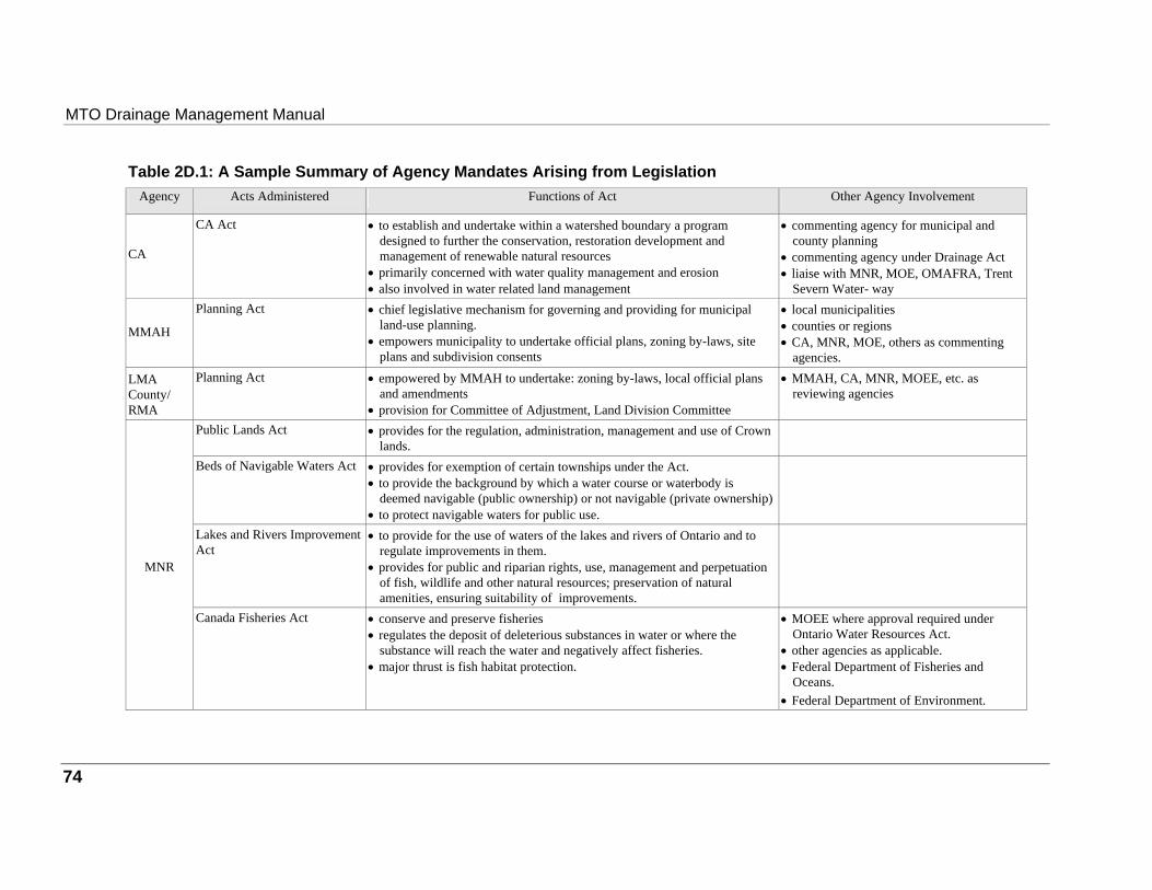
MTO Drainage Management Manual
Table 2D.1: A Sample Summary of Agency Mandates Arising from Legislation Agency Acts Administered Functions of Act Other Agency Involvement
CA
CA Act
• to establish and undertake within a watershed boundary a program
designed to further the conservation, restoration development and management of renewable natural resources
• primarily concerned with water quality management and erosion • also involved in water related land management
• commenting agency for municipal and
county planning • commenting agency under Drainage Act • liaise with MNR, MOE, OMAFRA, Trent
Severn Water- way
MMAH
Planning Act
• chief legislative mechanism for governing and providing for municipal
land-use planning. • empowers municipality to undertake official plans, zoning by-laws, site
plans and subdivision consents
• local municipalities • counties or regions • CA, MNR, MOE, others as commenting
agencies. LMA County/ RMA
Planning Act
• empowered by MMAH to undertake: zoning by-laws, local official plans
and amendments • provision for Committee of Adjustment, Land Division Committee
• MMAH, CA, MNR, MOEE, etc. as
reviewing agencies
Public Lands Act
• provides for the regulation, administration, management and use of Crown
lands.
Beds of Navigable Waters Act
• provides for exemption of certain townships under the Act. • to provide the background by which a water course or waterbody is
deemed navigable (public ownership) or not navigable (private ownership) • to protect navigable waters for public use.
Lakes and Rivers Improvement Act
• to provide for the use of waters of the lakes and rivers of Ontario and to
regulate improvements in them. • provides for public and riparian rights, use, management and perpetuation
of fish, wildlife and other natural resources; preservation of natural amenities, ensuring suitability of improvements.
MNR
Canada Fisheries Act
• conserve and preserve fisheries • regulates the deposit of deleterious substances in water or where the
substance will reach the water and negatively affect fisheries. • major thrust is fish habitat protection.
• MOEE where approval required under
Ontario Water Resources Act. • other agencies as applicable. • Federal Department of Fisheries and
Oceans. • Federal Department of Environment.
74
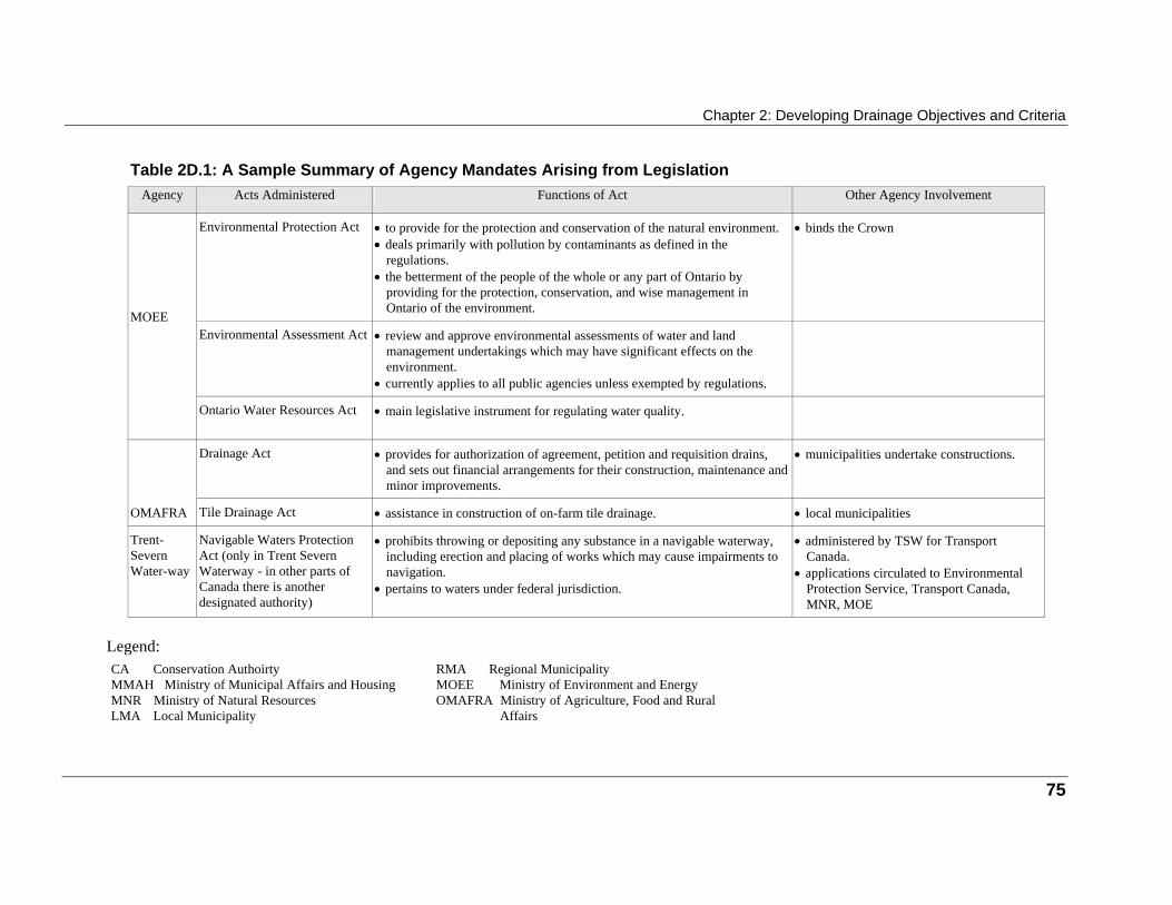
Chapter 2: Developing Drainage Objectives and Criteria
Table 2D.1: A Sample Summary of Agency Mandates Arising from Legislation Agency Acts Administered Functions of Act Other Agency Involvement
Environmental Protection Act
• to provide for the protection and conservation of the natural environment. • deals primarily with pollution by contaminants as defined in the
regulations. • the betterment of the people of the whole or any part of Ontario by
providing for the protection, conservation, and wise management in Ontario of the environment.
• binds the Crown
Environmental Assessment Act
• review and approve environmental assessments of water and land
management undertakings which may have significant effects on the environment.
• currently applies to all public agencies unless exempted by regulations.
MOEE
Ontario Water Resources Act
• main legislative instrument for regulating water quality.
Drainage Act
• provides for authorization of agreement, petition and requisition drains,
and sets out financial arrangements for their construction, maintenance and minor improvements.
• municipalities undertake constructions.
OMAFRA
Tile Drainage Act
• assistance in construction of on-farm tile drainage.
• local municipalities
Trent-Severn Water-way
Navigable Waters Protection Act (only in Trent Severn Waterway - in other parts of Canada there is another designated authority)
• prohibits throwing or depositing any substance in a navigable waterway,
including erection and placing of works which may cause impairments to navigation.
• pertains to waters under federal jurisdiction.
• administered by TSW for Transport
Canada. • applications circulated to Environmental
Protection Service, Transport Canada, MNR, MOE
Legend: CA Conservation Authoirty MMAH Ministry of Municipal Affairs and Housing MNR Ministry of Natural Resources LMA Local Municipality
RMA Regional Municipality MOEE Ministry of Environment and Energy OMAFRA Ministry of Agriculture, Food and Rural
Affairs
75
76
Appendix 2E: Documents Supporting Statutory
Mandates
Table 2E.1 presents the support document that arise from legislation administered by the various agencies.
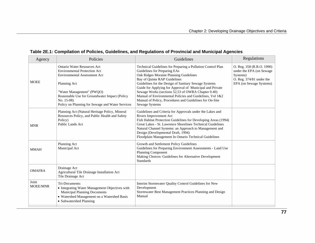
Chapter 2: Developing Drainage Objectives and Criteria
Table 2E.1: Compilation of Policies, Guidelines, and Regulations of Provincial and Municipal Agencies
Agency Policies Guidelines Regulations
MOEE
Ontario Water Resources Act Environmental Protection Act Environmental Assessment Act Planning Act "Water Management" (PWQO) Reasonable Use for Groundwater Impact (Policy No. 15-08) Policy on Planning for Sewage and Water Services
Technical Guidelines for Preparing a Pollution Control Plan Guidelines for Preparing EAs Oak Ridges Moraine Planning Guidelines Bay of Quinte RAP Guidelines Guidelines for the Design of Sanitary Sewage Systems Guide for Applying for Approval of Municipal and Private Sewage Works (sections 52,53 of OWRA Chapter 0.40) Manual of Environmental Policies and Guidelines, Vol 1&2 Manual of Policy, Procedures and Guidelines for On-Site Sewage Systems
O. Reg. 358 (R.R.O. 1990) under the EPA (on Sewage Systems) O. Reg. 374/81 under the EPA (on Sewage Systems)
MNR
Planning Act (Natural Heritage Policy, Mineral Resources Policy, and Public Health and Safety Policy) Public Lands Act
Guidelines and Criteria for Approvals under the Lakes and Rivers Improvement Act Fish Habitat Protection Guidelines for Developing Areas (1994) Great Lakes - St. Lawrence Shorelines Technical Guidelines Natural Channel Systems: an Approach to Management and Design (Developmental Draft, 1994) Floodplain Management In Ontario Technical Guidelines
MMAH
Planning Act Municipal Act
Growth and Settlement Policy Guidelines Guidelines for Preparing Environment Assessments - Land Use Planning Component Making Choices: Guidelines for Alternative Development Standards
OMAFRA
Drainage Act Agricultural Tile Drainage Installation Act Tile Drainage Act
Joint MOEE/MNR
Tri-Documents: • Integrating Water Management Objectives with
Municipal Planning Documents • Watershed Management on a Watershed Basis • Subwatershed Planning
Interim Stormwater Quality Control Guidelines for New Development Stormwater Best Management Practices Planning and Design Manual
77
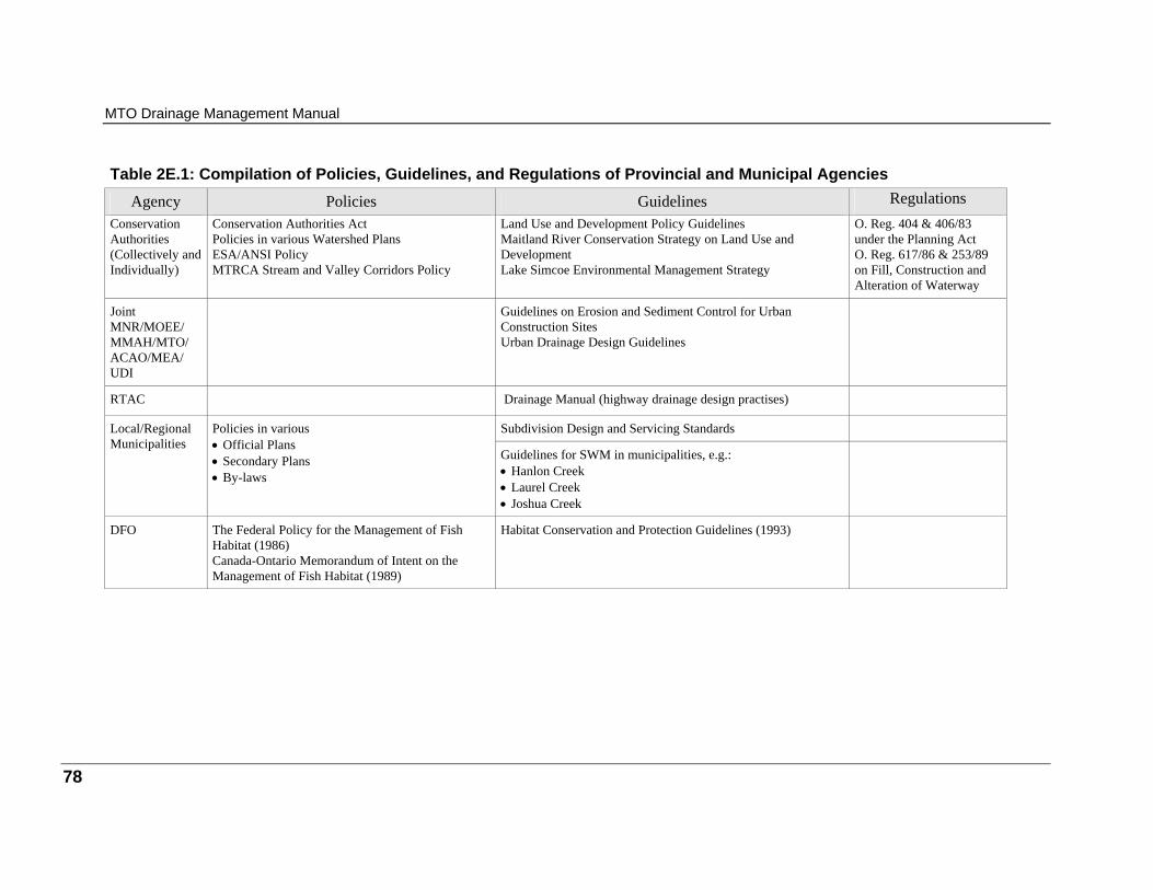
MTO Drainage Management Manual
Table 2E.1: Compilation of Policies, Guidelines, and Regulations of Provincial and Municipal Agencies
Agency Policies Guidelines Regulations Conservation Authorities (Collectively and Individually)
Conservation Authorities Act Policies in various Watershed Plans ESA/ANSI Policy MTRCA Stream and Valley Corridors Policy
Land Use and Development Policy Guidelines Maitland River Conservation Strategy on Land Use and Development Lake Simcoe Environmental Management Strategy
O. Reg. 404 & 406/83 under the Planning Act O. Reg. 617/86 & 253/89 on Fill, Construction and Alteration of Waterway
Joint MNR/MOEE/ MMAH/MTO/ ACAO/MEA/ UDI
Guidelines on Erosion and Sediment Control for Urban Construction Sites Urban Drainage Design Guidelines
RTAC
Drainage Manual (highway drainage design practises)
Subdivision Design and Servicing Standards
Local/Regional Municipalities
Policies in various • Official Plans • Secondary Plans • By-laws
Guidelines for SWM in municipalities, e.g.: • Hanlon Creek • Laurel Creek • Joshua Creek
DFO
The Federal Policy for the Management of Fish Habitat (1986) Canada-Ontario Memorandum of Intent on the Management of Fish Habitat (1989)
Habitat Conservation and Protection Guidelines (1993)
78
i
3 Table of Contents
Purpose of This Chapter 1 Introduction 3 Introducing Drainage Design within the Highway Planning and Design Process 5
Selection of study options 5 Preliminary design 5 Detail design 5
Developing the Drainage Design 6 Water crossing components 6 Surface drainage components 6 Stormwater management components 6
Analysing the Drainage Design 7 Evaluating the Drainage Design 8 Documenting the Drainage Design 8 Concluding Notes 9
The process is flexible 9 The process includes drainage 9 For rehabilitation, drainage works may be the project 9
A Quick Reference for Developing a Drainage Design 10 Developing a Water Crossing Design 17
Develop the stream modification 17 Develop the water crossing 17 The highway project 18 The planning and design process 18
The Need for Stream Channel Modifications 19 Adverse Impacts Associated with Stream Channel Modifications 20
Stream Channel Stability 20

MTO Drainage Management Manual
ii
Watershed Hydrology 21 Stream Channel Hydraulics 21 Riparian Land Owner Rights 21 Aquatic Habitat 22 Terrestrial Habitats 22 Water Quality 22
Location of the Water Crossing 23 Stream Channel Stability and Self-adjustment 23 Crossings at Aggrading and Degrading Channels 23 Crossings at Alluvial Fans and Deltas 24 Crossings at Braided Channels 24 Crossings at a Stream Confluence 24 Local Stream Channel Modifications 24 Crossing at Wetlands and Lakes 25 Possible Problems with Floating Debris 25 Factors Related to the Water Crossing and the Highway 25 External Constraints 25 Navigation Requirements 26 Water Crossings on Sag Curves 26
Water Crossings and the Highway Profile 26 Freeboard 26 Relief Flow 27 Relief Flow and the Highway Profile 28 Minor Access Routes under Water Crossings 28
Permanent Erosion Control Measures 29 Structure Performance 29 Soil and Foundation Considerations 30 Long Term Maintenance Considerations 30 Factors to Review When Considering a Bridge Crossing Option 30
Location and Alignment 31 Pier and Abutment Location and Alignment 31 Dual Parallel Bridges 32
Factors to Review When Considering a Culvert Crossing Option 32 Location and Alignment 32 Culvert Profile 33 Culvert Embedment 33
Chapter 3: Developing and Evaluating Design Alternatives
iii
Culvert Length 34 Relative Advantages of Bridges, As Compared to Culverts 34 Relative Advantages of Culverts, As Compared to Bridges 35 Locating Fish Habitat Structures within a Stream 35 Consider Data Needs 36
Proposed Crossing 36 Existing Structures 36 Local Information 37 Soils Information 37 Fish Migration Data 37
Completing a Bridge Crossing Design 39 Considerations at this Stage of the Bridge Crossing Design 39
Hydraulic Problems At Bridge Crossings 39 Span Arrangement 40 Pier Details 40 Abutments 40 Superstructures 41 Soffit Elevation 41
Applicable Hydrologic Methods for Bridge Crossing Design 41 Applicable Hydraulic Methods for Bridge Crossing Design 42 Information Sources and Working Details for Bridge Crossing Design 42 Completing a Culvert Crossing Design 44 Considerations at this Stage of the Culvert Crossing Design 44
Common Hydraulic Problems 44 Open Footing Versus Closed Invert Culverts 45 Culvert Material 45 Culvert Shape 46 Multi-Barrel Culverts 46 Culvert Profile 46 Culvert Length 47 Culvert Safety Concerns 47 Fish Passage Design Flow 47 Clay Seals 47 Other Considerations 48
MTO Drainage Management Manual
iv
Applicable Hydraulic Methods for Culvert Crossing Design 48 Information Sources and Working Details for Culvert Crossing Design 49 Completing a Stream Channel Modification Design 50 Considerations at this Stage of the Stream Modification Design 50 Applicable Hydrologic Methods for Stream Modification Design 51 Applicable Hydraulic Methods for Stream Modification Design 52 Information Sources and Working Details for Stream Channel Modification Design 52 Developing a Surface Drainage Design 53
The minor drainage system 53 The major drainage system 53 The highway project 54 The planning and design process 54
Selection of the Minor Drainage System 55 Advantages of Storm Sewers as Compared to Roadside Ditches 55 Advantages of Roadside Ditches as Compared to Storm Sewers 55 Checking the Major Drainage System 56 Checking the Receiving System 56 Considering Data Needs 57 Completing a Storm Sewer Design 58 Considerations at this Stage of the Storm Sewer Design 58 Applicable Hydrologic Methods for Storm Sewer Design 58 Applicable Hydraulic Methods for Storm Sewer Design 59 Information Sources and Working Details for Storm Sewer Design 59 Completing a Roadside Ditch Design 60 Considerations at this Stage of the Roadside Ditch Design 60 Applicable Hydrologic Methods for Roadside Ditch Design 60 Applicable Hydraulic Methods for Roadside Ditch Design 61 Information Sources and Working Details for Roadside Ditch Design 61 Completing a Major Drainage System Design 62 Considerations at this Stage of the Major Drainage System 62
Chapter 3: Developing and Evaluating Design Alternatives
v
Applicable Hydrologic Methods for Major Drainage System Design 63 Applicable Hydraulic Methods for Major Drainage System Design 63 Information Sources and Working Details for Major Drainage System Design 63 Developing a Stormwater Management Design 64
The highway project 65 The planning and design process 65
The Current Approach to Stormwater Management 66 Stormwater Impacts Associated with Highways 66
Stormwater Quantity Impacts 66 Stormwater Quality Impacts 67
Typical Contaminants Associated with Highway Stormwater 67 Identification of Best Management Practices Suitable for Highways 68
General Considerations 68 BMPs Suitable for Highway Development 70
Receiving Water Based Quality Control Criteria 72 Assessing the Need for Stormwater Quality and Quantity Control 73
Need For Stormwater Quality Control 73 Need For Stormwater Quantity Control 74
Location and Layout Plan of the Stormwater Management System 74 Completing a Stormwater Quality Control Facility Design (i.e. Wet Pond, Extended Detention Pond) 75 Considerations at this Stage of the Quality Control Facility Design 75
Size 75 Length to Width Ratio 76 Detention Time 76 Inlet and Outlet Configuration 77 Emergency Bypass Location, Type and Capacity 77 Maintenance Access 77 Special Safety and Maintenance Requirements 77 Grading and Planting Strategy 78 Other Design Considerations 78
Applicable Hydrologic Methods for Quality Control Facility Design 78 Single Event Simulation 78 The DPD Method 79
MTO Drainage Management Manual
vi
Continuous Simulation 79 Applicable Hydraulic Methods for Quality Control Facility Design 80
Reservoir Sizing 80 Reservoir Routing 80
Completing a Stormwater Quantity Control Facility Design (i.e. Dry Ponds) 82 Consideration at this Stage of the Quantity Control Facility Design 82
Size 82 Detention Time 83 Inlet and Outlet Configuration 83 Emergency Bypass Location, Type and Capacity 84 Maintenance Access 84 Special Safety and Maintenance Requirements 84 Grading and Planting Strategy 84 Other Design Considerations 84
Applicable Hydrologic Methods For Quantity Control Facility Design 85 Single Event Modelling 85
Applicable Hydraulic Methods for Quantity Control Facility Design 85 Reservoir Sizing 86 Reservoir Routing 86
References 87 Appendix 3A: Hydrologic Computational Procedures 90 Is Hydrograph Simulation Required? 91 Hydrograph Simulation Is Required - Select The Modeling Approach 91
Single Event Modeling 91 Continuous Event Modeling 94
Hydrologic Computer Model Applications 95 Calibration and Verification of Hydrologic Computer Modelling 96
Hydrograph Simulation Is Not Required and Flow Records Exist 97 Single Station Frequency Analysis 97
Hydrograph Simulation is Not Required and Flow Records Do Not Exist 98 Rational Method 98 Regional Frequency Analysis 99
Chapter 3: Developing and Evaluating Design Alternatives
vii
Appendix 3B: Hydraulic Computational Procedures 100 Flow Analysis 100
Hydraulic Computer Model Applications 102 Computer Application Errors 103
Calibration and Verification of Hydraulic Computer Modelling 103 Selection of an Appropriate Computational Method 104
Culvert Hydraulics 104 Flow with Inlet Control 104 Flow With Outlet Control 106 Analysis Approach 106
Reservoir Sizing and Routing 106 Reservoir Sizing 106 Reservoir Routing 107
Stream Channel Sizing and Routing 107 Stream Channel Sizing 107 Stream Channel Routing 107
Stream Channel Stability Analysis 107 Tractive force 108 The permissible velocity 108 Scour analysis 108
Appendix 3C: Evaluation 109 What Is Evaluation? 109 Why Do Evaluations? 109 Input from Earlier Tasks 110 What is Included in an Evaluation Process? 110 Keep the Evaluation Simple 111 Give All Stakeholder an Opportunity to Be Heard 111 Do Not Bias the Evaluation by Your Choice of Methods 111 The Evaluation Team 112 Public Consultation 112 Evaluation Methods 113 Approaches To Valuing Impacts 113
Monetary Measures 113 Non-Monetary Measures 113 Capital Costs 114
MTO Drainage Management Manual
viii
Estimating Capital Costs - Unit Costing 114 Operating and Maintenance Costs 116 Estimating Operating and Maintenance Costs 116 Valuation of Land Required for Construction 117 Impacts on Adjacent Lands 118 Monetary Assessment of Impacts on Adjacent Agricultural and Commercial Lands 119 Flood Damages 120 Other Impacts Related To Adjacent Property 121 Travel Costs 121 Impacts on Recreation 122
Equivalent Measures of Monetary Value 123 Common Life Spans 123
Life Cycle Costing 123 Accounting for Inflation 124 The Current Value of Future Dollars 124
Comparing Options 125 Cost Benefit Analysis 125 Cost Effectiveness Analysis 126 The Impact Matrix 126 Using the Impact Matrix in Making Decision 127
Output from the Evaluation Task 129 Use of the Output 129 List of Figures Figure 3.1: The Drainage Design Process 2 Figure 3.2: Highway Alternatives and Associated Components of Drainage Options 10 Figure 3.3: Developing a Drainage Design 11 Figure 3.4: Stormwater Quantity and Quality Control 68 Figure 3A.1: Hydrologic Methodology 90 List of Tables Table 3.1 a: Bridge Crossing Design 12 Table 3.1 b: Culvert Crossing Design 13 Table 3.1 c: Stream Modification Design 14 Table 3.1 d: Surface Drainage Design 15 Table 3.1 e: Stormwater Management System Design 16
Chapter 3: Developing and Evaluating Design Alternatives
ix
Table 3.2: Fitting the Water Crossing Options to the Highway Alternative 18 Table 3.3: Fitting the Surface Drainage Options to the Highway Alternative 54 Table 3.4: Fitting the Stormwater Management Options to the Highway Alternative 65 Table 3.5: Water Quantity Control Measures 69 Table 3.6: Water Quality Control Mechanisms 69 Table 3A.1 Single Storm Events 92 Table 3A.2: Design Storm Criteria 93 Table 3A.3: Hydrologic Computer Model Applications 96 Table 3B.1: Hydraulic Computer Model Applications 105 Table 3C.1 - Unit Costing of Study Options and Preliminary Design 116
1
Purpose of This Chapter
The purpose of this chapter is to present the methodology for developing drainage designs for highway projects and illustrate how the development of drainage designs "fit" within the Highway Planning and Design Process. Figure 3.1 presents the stages of development of drainage designs as part of the highway planning and design process. The focus, in this chapter, will be on outlining the thought process for the preparation of drainage designs. The design considerations, levels of detail, and the choice of numerical methods required for the analysis associated with the different stages of design will be discussed. Design details of specific drainage components will be covered in Part 2 of the manual. Due to the interdisciplinary nature associated with the development of a drainage design, it is intended that this chapter clearly identify areas where consultation with, and involvement of, other professional disciplines is required. Information that is not directly related to drainage is included only for: • information purposes; • to familiarize the drainage practitioner with the language of other disciplines; and • to familiarize the drainage practitioner with the issues that are shared between the different
disciplines. Solutions to impacts not directly related to drainage design are outside the scope of this manual, and are discussed in other MTO documents such as the: • Environmental Manual, Fisheries; or • Environmental Manual, Sediment and Erosion Control (Working Draft). When designing solutions to drainage related impacts, advantages gained through the interdisciplinary team approach cannot be overstressed. It should be noted that specific design objectives, criteria, and options for an individual highway project, including the drainage management components, will be established by the project through the class environmental assessment process. The material presented in this chapter is intended to be read and used in this context.

MTO Drainage Management Manual
2
Figure 3.1: The Drainage Design Process
The Highway Planning and Design Process
Obtain Data and Input From Previous
Determine Drainage Impacts
Determine Drainage
Objectives & Criteria (Note 2)
Are Drainage Impacts
Identified ?
Are Drainage Objectives & Criteria
Determined ?
Yes
Yes
No
No
Study Options
DEVELOP
ANALYZE
EVALUATE
DOCUMENTDrainage
Are Project Objectives
& Criteria Satisfied ?
Preliminary Design Drainage
Detail Design Drainage
Yes ANALYZE
EVALUATE
DOCUMENT
ANALYZE
EVALUATE
DOCUMENT
No
No
Yes
Are Project Objectives
& Criteria Satisfied ?
Drainage Tasks
3
Introduction
The development of highways will, in most cases, impact the surrounding environment. One of the means of addressing these impacts in the design of highways is the adoption of modern drainage management techniques. The concept of modern drainage management is based on the belief that the most effective means of addressing the impacts of a highway development is through the adoption of a design methodology that will : • achieve the objectives of the highway development; and, • account for the limitations and constraints of the surrounding natural, social and economic
environment. The design methodology can be accomplished in three steps, as follows. 1. Identification of drainage impacts. 2. Determination of objectives and criteria for drainage design. 3. Development of the drainage design. Chapter 2 provides guidance on how to complete the first two steps. This chapter takes the next step. It describes the methodology that can be used to incorporate the output from the previous two steps, into the design of a preferred drainage option. Any drainage option should, therefore, satisfy the constraints and requirements of the highway alternative being considered, as well as the constraints and limitations set by the surrounding natural and social environment. As described in Chapter 2, the drainage-related objectives and criteria for a highway project are derived based on the potential watershed impacts of the highway project and associated drainage works. These objectives and criteria are also a reflection of the governing laws, codes, policies, standards, and guidelines. Therefore, a wide range of issues may be involved in the design of drainage works. This will require the involvement of an interdisciplinary team which may include engineers, planners, biologists and landscape architects. In order for a drainage design to satisfy the wide range of objectives and criteria established for the project, design criteria will need to be considered for the following: • hydrology; • hydraulics (including geomorphology); • soil erosion; • water quality • terrestrial biota; • aquatic biota; and
MTO Drainage Management Manual
4
• socioeconomic factors. This chapter will focus on the design methodology related to hydrology, hydraulics, and water quality. Guidance on design considerations related to aquatic biota, terrestrial biota and socioeconomic factors are beyond the scope of this manual and will be left to other relevant MTO manuals and external references to provide the required guidance. It is important to note, however, that the consideration of aquatic biota, terrestrial biota and socioeconomic factors is an integral part of developing the project objectives and criteria. These criteria provide the principles that guide the design of the highway drainage works.
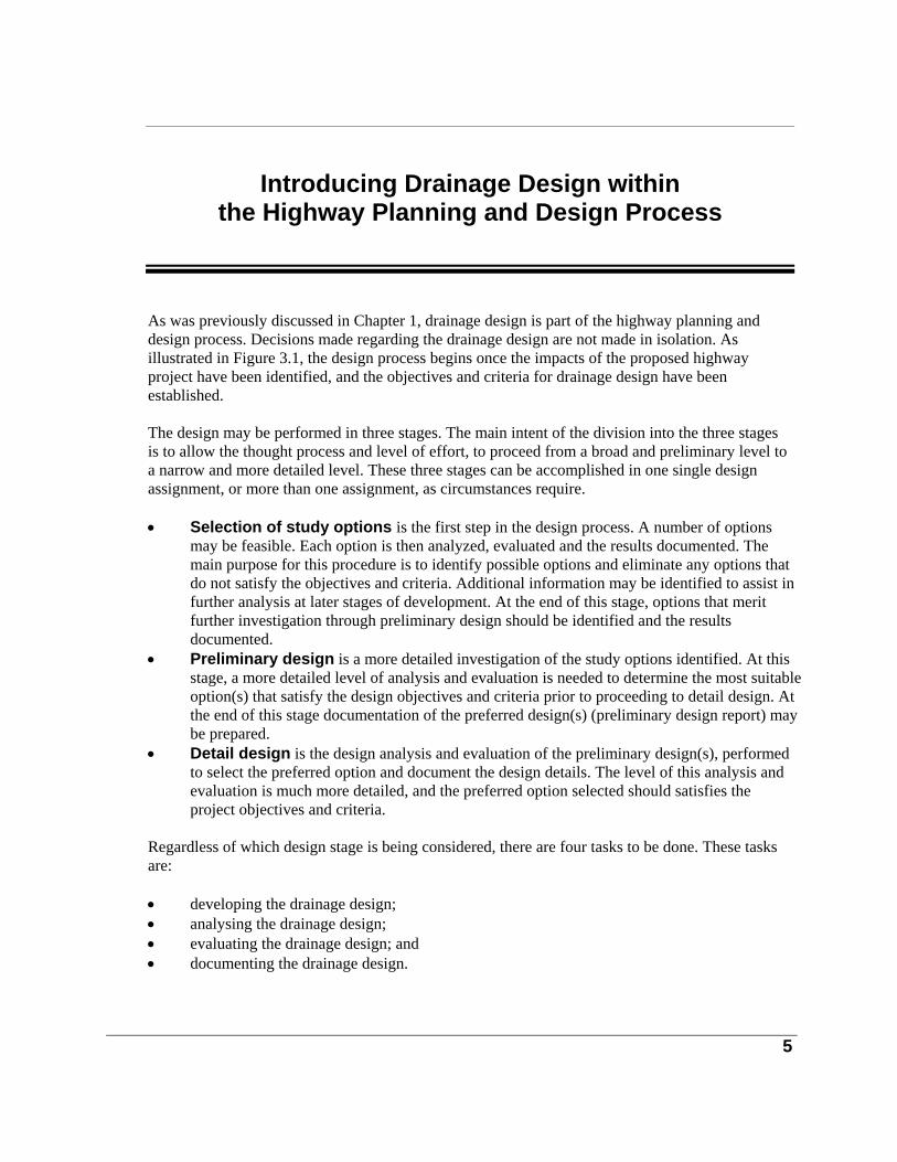
5
Introducing Drainage Design within the Highway Planning and Design Process
As was previously discussed in Chapter 1, drainage design is part of the highway planning and design process. Decisions made regarding the drainage design are not made in isolation. As illustrated in Figure 3.1, the design process begins once the impacts of the proposed highway project have been identified, and the objectives and criteria for drainage design have been established. The design may be performed in three stages. The main intent of the division into the three stages is to allow the thought process and level of effort, to proceed from a broad and preliminary level to a narrow and more detailed level. These three stages can be accomplished in one single design assignment, or more than one assignment, as circumstances require. • Selection of study options is the first step in the design process. A number of options
may be feasible. Each option is then analyzed, evaluated and the results documented. The main purpose for this procedure is to identify possible options and eliminate any options that do not satisfy the objectives and criteria. Additional information may be identified to assist in further analysis at later stages of development. At the end of this stage, options that merit further investigation through preliminary design should be identified and the results documented.
• Preliminary design is a more detailed investigation of the study options identified. At this stage, a more detailed level of analysis and evaluation is needed to determine the most suitable option(s) that satisfy the design objectives and criteria prior to proceeding to detail design. At the end of this stage documentation of the preferred design(s) (preliminary design report) may be prepared.
• Detail design is the design analysis and evaluation of the preliminary design(s), performed to select the preferred option and document the design details. The level of this analysis and evaluation is much more detailed, and the preferred option selected should satisfies the project objectives and criteria.
Regardless of which design stage is being considered, there are four tasks to be done. These tasks are: • developing the drainage design; • analysing the drainage design; • evaluating the drainage design; and • documenting the drainage design.

MTO Drainage Management Manual
6
Developing the drainage design is introduced below. Since this task is the main scope of this manual, a detailed discussion that specifically focuses on developing the drainage design for the preliminary and detail design stages, is presented in subsequent sections (refer to Figure 3.3). Analysis of the drainage design will be discussed throughout the manual. The other tasks, evaluation and documentation, are part of the broader highway planning and design process, and will not be discussed in any great detail within this manual. The level to which each of the tasks is completed will depend on the scope and scale of the project. Figure 3.1 illustrates the linkage between the three design stages and the four main tasks.
Developing the Drainage Design A highway project will generally include one or more of the following elements: • horizontal and vertical alignments; • widenings; • interchanges; • ancillary facilities, such as car pool areas; and • rehabilitation. Depending on the scale of the highway project, each of the highway elements may include other components, of which drainage is one component. Drainage components can be grouped as follows. • Water crossing components are drainage works that are associated with a
highway crossing of a stream, river, creek or lake . These components include culverts, bridges, and stream modifications, such as, diversions, channelization, and enclosures.
• Surface drainage components are drainage works that collect and transport stormwater runoff from the highway right-of-way and surrounding catchment, to a receiving body of water such as stream, river, or lake. These components include ditches, storm sewers, and the major flow system.
• Stormwater management components are drainage works that are needed to control stormwater runoff. These components are either quantity control or quality control facilities. Quantity control facilities detain runoff for a required period of time before releasing it at a specified rate. Water quality control facilities treat surface runoff and reduce the amount of pollutants released to the environment. In some cases either quantity or quality control is needed. In other instances, both are required and can be provided in separate or combined facilities.
To develop a drainage option, identify the different drainage components required for the highway project. The selection of different combinations of components will result in different drainage options. Figure 3.2 illustrates the drainage options associated with different highway elements.
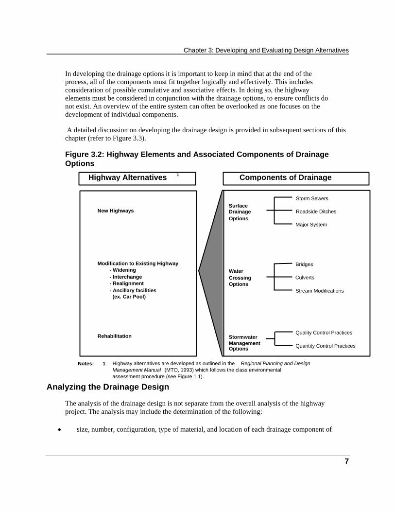
Chapter 3: Developing and Evaluating Design Alternatives
7
In developing the drainage options it is important to keep in mind that at the end of the process, all of the components must fit together logically and effectively. This includes consideration of possible cumulative and associative effects. In doing so, the highway elements must be considered in conjunction with the drainage options, to ensure conflicts do not exist. An overview of the entire system can often be overlooked as one focuses on the development of individual components. A detailed discussion on developing the drainage design is provided in subsequent sections of this chapter (refer to Figure 3.3). Figure 3.2: Highway Elements and Associated Components of Drainage Options
Analyzing the Drainage Design The analysis of the drainage design is not separate from the overall analysis of the highway project. The analysis may include the determination of the following:
• size, number, configuration, type of material, and location of each drainage component of
Highway Alternatives Components of Drainage
New Highways
Modification to Existing Highway- Widening - Interchange - Realignment - Ancillary facilities (ex. Car Pool)
Rehabilitation
Surface DrainageOptions
Water Crossing Options
Stormwater Management Options
Storm Sewers
Roadside Ditches
Major System
Quality Control Practices
Quantity Control Practices
Bridges Culverts Stream Modifications
P
1
Notes: 1 Highway alternatives are developed as outlined in the Regional Planning and Design Management Manual (MTO, 1993) which follows the class environmental assessment procedure (see Figure 1.1).

MTO Drainage Management Manual
8
the related highway element; • estimate of natural, social and economic impacts of the drainage option; • land requirements; • construction cost; • road closings or detours; and • long term maintenance requirements. The analysis of drainage designs takes place throughout the study option, preliminary design and detailed design stages. When analyzing drainage study options, the level of detail required in the calculation is limited. The goal is to identify the possible drainage components and determine the approximate values of quantifiable design parameters. At this stage the practitioner may be able to evaluate and eliminate any options that are not feasible, or that clearly do not meet the design objectives and criteria. On the other hand, at the preliminary design stage the design of drainage facilities usually requires accurate identification of design parameters such as flow rate, storage capacities and water elevations, as well as the comparison of post development conditions to existing hydraulic and hydrologic conditions. Depending on the nature of the project, considerable effort could be spent in such an analysis. This analysis would provide the data and information required for the evaluation and selection of a preferred study option(s), prior to proceeding to detail design. Analysis at the detail design stage may be similar to the analysis performed at the preliminary design stage. However, the analysis will be more detailed and will give complete consideration to detailed site conditions. In some cases, a more accurate design method or computer model may have to be used which requires significantly more effort.
Evaluating the Drainage Design The evaluation of the drainage design is part of the overall evaluation of the highway project and will, therefore, not be discussed in any detail. This task helps to identify the best option or alternative, through a comparison of their relative values. The best option is one that: • achieves the same results as other options but at a lower cost; or • costs the same but has fewer adverse effects; or • costs more but has additional benefits that justify the extra cost. For a detailed discussion on the process of evaluation of drainage designs, refer to Appendix 3C.
Documenting the Drainage Design For each highway alternative that includes a drainage option, a design report may be prepared at each of the design stages. These reports will serve to document the results of the development, analysis and evaluation tasks at each stage. In general this report should include all data and calculations relevant to the design(s) of the preferred drainage option(s), including input and output

Chapter 3: Developing and Evaluating Design Alternatives
9
data and information, computer input and output files, drawings of the drainage plan(s) in relation to the highway development plan(s) and the contributing watershed, all necessary dimensions, water levels, protective works, and other information related to the design. The items identified above are by no means complete. Examples of reporting requirements can be found in MTO’s Guidelines for Preparation of Hydraulics Reports. More details are also provided in Chapters 4 and 5 in Part 2 and Chapter 8 in Part 3.
Concluding Notes When evaluating the process presented in Figure 3.1 and Figure 3.2, the following points need to be considered. • The process may be iterative. Design requirements, public concerns, scientific
information, natural environment issues and awareness of environmental processes may change. Consequently, objectives and criteria may have to be modified and new design options considered which can result in the design procedure being an iterative process.
• The process is flexible. All steps in the highway planning and design process are not always needed nor followed in the specific order of presentation (i.e. as in Figure 3.1). The process is not rigid and need not be divided into separate stages. For instance, the completion of the study options and preliminary design may be done in one step if, for example, only one design option is being considered. The exact sequence of the process will depend on the scale and nature of each project.
• The process includes drainage. Drainage design is an integral part of the highway planning and design process. Correspondingly, the primary purpose of the Drainage Management Manual is to provide highway design practitioners with guidance on the design of drainage works in support of the highway planning and design process.
• For rehabilitation, drainage works may be the project. In most instances, the highway project will involve the design or construction of highway elements, such as widenings, realignments, interchanges, and the associated drainage component. However, in some cases the project may only involve drainage works. For example, a project may involve the analysis of culvert crossings to determine effectiveness, potential liabilities and long term maintenance requirements. Considerations, in such a case, will mostly be drainage related.
It is outside the scope of this manual to discuss specific design procedures related to the broader highway planning and design process, and, more specifically, how each of the four tasks are completed within the three design stages. It will be the responsibility of the practitioner to apply the drainage design procedures and guidance appropriately.
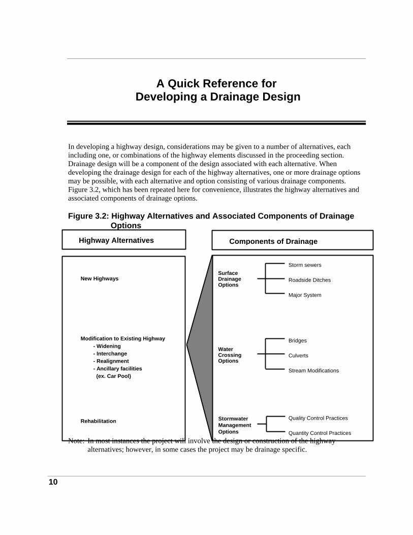
10
A Quick Reference for Developing a Drainage Design
In developing a highway design, considerations may be given to a number of alternatives, each including one, or combinations of the highway elements discussed in the proceeding section. Drainage design will be a component of the design associated with each alternative. When developing the drainage design for each of the highway alternatives, one or more drainage options may be possible, with each alternative and option consisting of various drainage components. Figure 3.2, which has been repeated here for convenience, illustrates the highway alternatives and associated components of drainage options. Figure 3.2: Highway Alternatives and Associated Components of Drainage
Options Note: In most instances the project will involve the design or construction of the highway
alternatives; however, in some cases the project may be drainage specific.
Highway Alternatives
Rehabilitation
Modification to Existing Highway - Widening - Interchange - Realignment - Ancillary facilities (ex. Car Pool)
New Highways
Components of Drainage
Stream Modifications
Bridges Culverts
Quantity Control Practices
Quality Control Practices
Storm sewers Roadside Ditches Major System
Stormwater Management Options
Water Crossing Options
Surface DrainageOptions
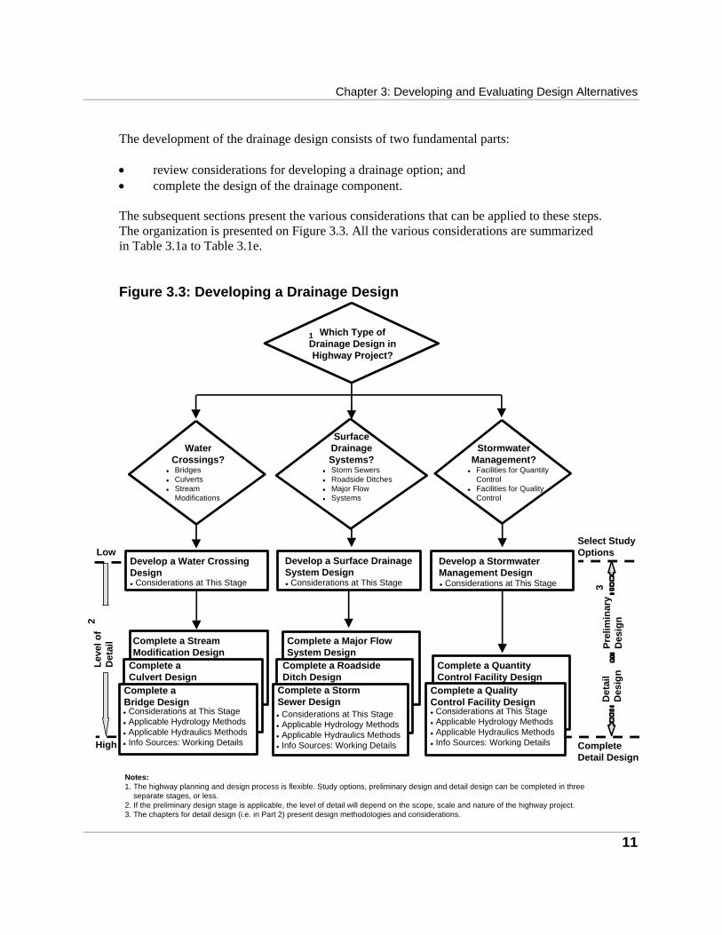
Chapter 3: Developing and Evaluating Design Alternatives
11
The development of the drainage design consists of two fundamental parts: • review considerations for developing a drainage option; and • complete the design of the drainage component. The subsequent sections present the various considerations that can be applied to these steps. The organization is presented on Figure 3.3. All the various considerations are summarized in Table 3.1a to Table 3.1e. Figure 3.3: Developing a Drainage Design
Which Type ofDrainage Design inHighway Project?
1
BridgesCulvertsStreamModifications
WaterCrossings?
SurfaceDrainageSystems?Storm SewersRoadside DitchesMajor FlowSystems
StormwaterManagement?
Facilities for QuantityControlFacilities for QualityControl
Complete a StreamModification Design
Complete aCulvert Design
Complete aBridge Design Considerations at This Stage Applicable Hydrology Methods Applicable Hydraulics Methods Info Sources: Working Details
Complete a StormSewer Design Considerations at This Stage Applicable Hydrology Methods Applicable Hydraulics Methods Info Sources: Working Details
Complete a RoadsideDitch Design
Complete a Major FlowSystem Design
High
Low
Notes:1. The highway planning and design process is flexible. Study options, preliminary design and detail design can be completed in three
separate stages, or less.2. If the preliminary design stage is applicable, the level of detail will depend on the scope, scale and nature of the highway project.3. The chapters for detail design (i.e. in Part 2) present design methodologies and considerations.
Leve
l of
Det
ail
2
Develop a Water CrossingDesign
Develop a Surface DrainageSystem Design
Det
ail
Des
ign
Select StudyOptions
CompleteDetail Design
3Pr
elim
inar
yD
esig
n
Develop a StormwaterManagement Design
Considerations at This Stage Considerations at This Stage Considerations at This Stage
Complete a QuantityControl Facility Design
Complete a QualityControl Facility Design Considerations at This Stage Applicable Hydrology Methods Applicable Hydraulics Methods Info Sources: Working Details
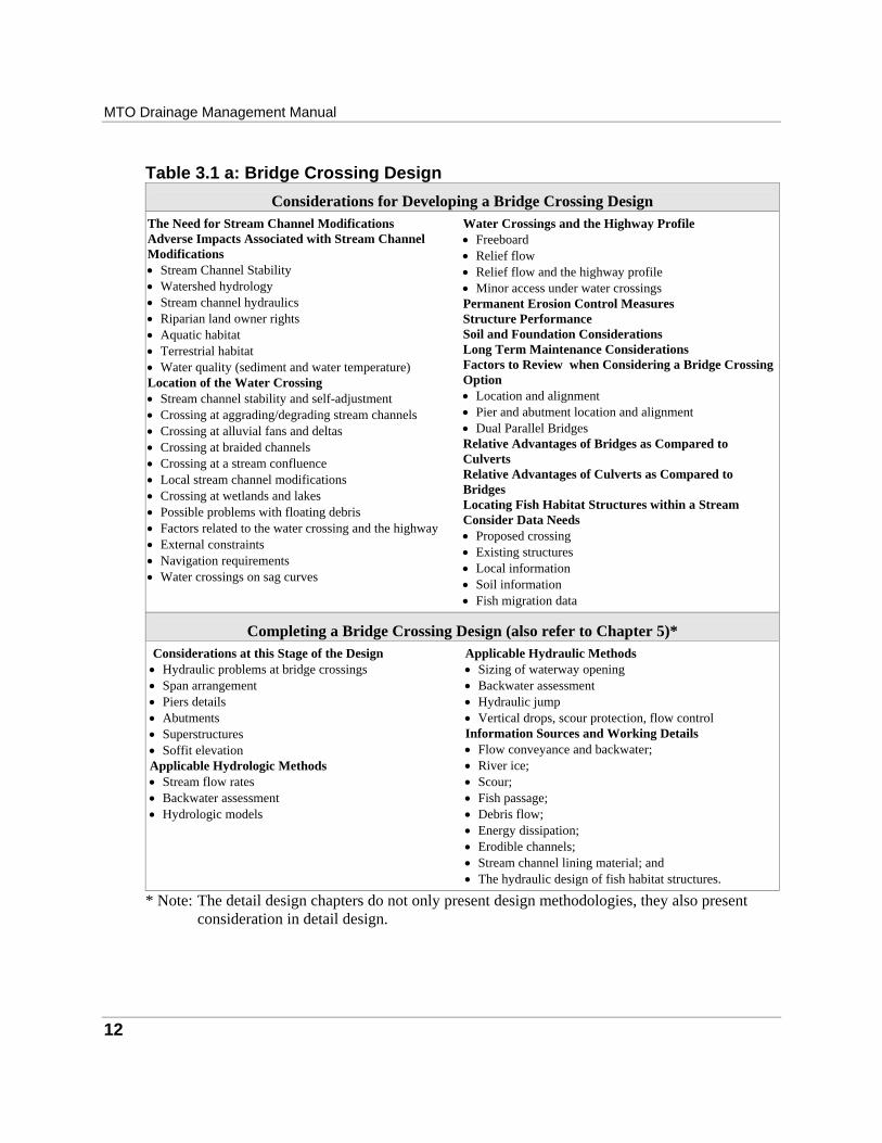
MTO Drainage Management Manual
12
Table 3.1 a: Bridge Crossing Design
Considerations for Developing a Bridge Crossing Design The Need for Stream Channel Modifications Adverse Impacts Associated with Stream Channel Modifications • Stream Channel Stability • Watershed hydrology • Stream channel hydraulics • Riparian land owner rights • Aquatic habitat • Terrestrial habitat • Water quality (sediment and water temperature) Location of the Water Crossing • Stream channel stability and self-adjustment • Crossing at aggrading/degrading stream channels • Crossing at alluvial fans and deltas • Crossing at braided channels • Crossing at a stream confluence • Local stream channel modifications • Crossing at wetlands and lakes • Possible problems with floating debris • Factors related to the water crossing and the highway • External constraints • Navigation requirements • Water crossings on sag curves
Water Crossings and the Highway Profile • Freeboard • Relief flow • Relief flow and the highway profile • Minor access under water crossings Permanent Erosion Control Measures Structure Performance Soil and Foundation Considerations Long Term Maintenance Considerations Factors to Review when Considering a Bridge Crossing Option • Location and alignment • Pier and abutment location and alignment • Dual Parallel Bridges Relative Advantages of Bridges as Compared to Culverts Relative Advantages of Culverts as Compared to Bridges Locating Fish Habitat Structures within a Stream Consider Data Needs • Proposed crossing • Existing structures • Local information • Soil information • Fish migration data
Completing a Bridge Crossing Design (also refer to Chapter 5)* Considerations at this Stage of the Design • Hydraulic problems at bridge crossings • Span arrangement • Piers details • Abutments • Superstructures • Soffit elevation Applicable Hydrologic Methods • Stream flow rates • Backwater assessment • Hydrologic models
Applicable Hydraulic Methods • Sizing of waterway opening • Backwater assessment • Hydraulic jump • Vertical drops, scour protection, flow control Information Sources and Working Details • Flow conveyance and backwater; • River ice; • Scour; • Fish passage; • Debris flow; • Energy dissipation; • Erodible channels; • Stream channel lining material; and • The hydraulic design of fish habitat structures.
* Note: The detail design chapters do not only present design methodologies, they also present consideration in detail design.

Chapter 3: Developing and Evaluating Design Alternatives
13
Table 3.1 b: Culvert Crossing Design
Considerations for Developing a Culvert Crossing Design The Need for Stream Channel Modifications Adverse Impacts Associated with Stream Channel Modifications • Stream Channel Stability • Watershed hydrology • Stream channel hydraulics • Riparian land owner rights • Aquatic habitat • Terrestrial habitat • Water quality (sediment and water temperature) Location of the Water Crossing • Stream channel stability and self-adjustment • Crossing at aggrading/degrading stream channels • Crossing at alluvial fans and deltas • Crossing at braided channels • Crossing at a stream confluence • Local stream channel modifications • Crossing at wetlands and lakes • Possible problems with floating debris • Factors related to the water crossing and the highway • External constraints • Navigation requirements • Water crossings on sag curves Water Crossings and the Highway Profile • Freeboard • Relief flow
Water Crossings and the Highway Profile (con’t) • Relief flow and the highway profile • Minor access under water crossings Permanent Erosion Control Measures Structure Performance Soil and Foundation Considerations Long Term Maintenance Considerations Factors to Review When Considering a Culvert Crossing Option • Location and alignment • Culvert profile • Culvert embedment • Culvert length Relative Advantages of Bridges as Compared to Culverts Relative Advantages of Culverts as Compared to Bridges Locating Fish Habitat Structures within a Stream Consider Data Needs • Proposed crossing • Existing structures • Local information • Soil information • Fish migration data
Completing a Culvert Crossing Design (also refer to Chapter 5)*
Considerations at this Stage • Common hydraulic problems • Open footing versus closed invert culverts • Culvert Material • Culvert shape • Multi-barrel culverts • Culvert profile • Culvert length • Culvert Safety Concerns • Fish passage design flow • Clay seals • Other-tailwater level, improved inlets, end treatments and
embankment fills Applicable Hydrologic Methods • Stream flow • Peak flow computation • Hydrograph computation / Hydrologic models • Flood plain impacts
Applicable Hydraulic Methods • Sizing of waterway opening • Inlet and outlet control • Hydraulic jump • Backwater assessment • Vertical drops, scour protection, flow control Information Sources and Working Details • Flow through culverts • River ice • Scour • Fish passage • Debris flow • Energy dissipation • Erodible stream channels • Stream channel lining material • The hydraulic design of fish habitat structures
* Note: The detail design chapters do not only present design methodologies, they also present consideration in detail design.
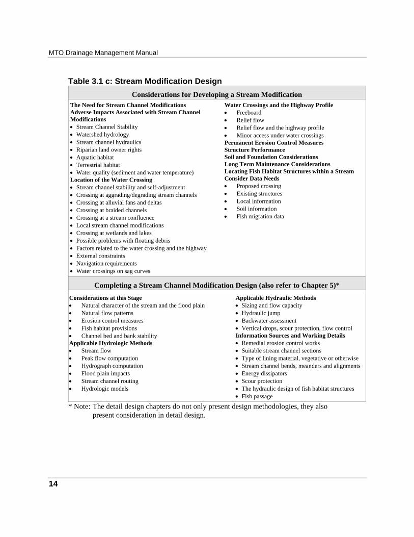
MTO Drainage Management Manual
14
Table 3.1 c: Stream Modification Design
Considerations for Developing a Stream Modification The Need for Stream Channel Modifications Adverse Impacts Associated with Stream Channel Modifications • Stream Channel Stability • Watershed hydrology • Stream channel hydraulics • Riparian land owner rights • Aquatic habitat • Terrestrial habitat • Water quality (sediment and water temperature) Location of the Water Crossing • Stream channel stability and self-adjustment • Crossing at aggrading/degrading stream channels • Crossing at alluvial fans and deltas • Crossing at braided channels • Crossing at a stream confluence • Local stream channel modifications • Crossing at wetlands and lakes • Possible problems with floating debris • Factors related to the water crossing and the highway • External constraints • Navigation requirements • Water crossings on sag curves
Water Crossings and the Highway Profile • Freeboard • Relief flow • Relief flow and the highway profile • Minor access under water crossings Permanent Erosion Control Measures Structure Performance Soil and Foundation Considerations Long Term Maintenance Considerations Locating Fish Habitat Structures within a Stream Consider Data Needs • Proposed crossing • Existing structures • Local information • Soil information • Fish migration data
Completing a Stream Channel Modification Design (also refer to Chapter 5)* Considerations at this Stage • Natural character of the stream and the flood plain • Natural flow patterns • Erosion control measures • Fish habitat provisions • Channel bed and bank stability Applicable Hydrologic Methods • Stream flow • Peak flow computation • Hydrograph computation • Flood plain impacts • Stream channel routing • Hydrologic models
Applicable Hydraulic Methods • Sizing and flow capacity • Hydraulic jump • Backwater assessment • Vertical drops, scour protection, flow control Information Sources and Working Details • Remedial erosion control works • Suitable stream channel sections • Type of lining material, vegetative or otherwise • Stream channel bends, meanders and alignments • Energy dissipators • Scour protection • The hydraulic design of fish habitat structures • Fish passage
* Note: The detail design chapters do not only present design methodologies, they also present consideration in detail design.
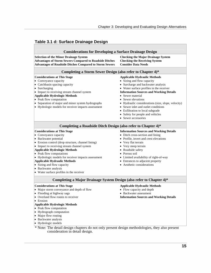
Chapter 3: Developing and Evaluating Design Alternatives
15
Table 3.1 d: Surface Drainage Design
Considerations for Developing a Surface Drainage Design Selection of the Minor Drainage System Advantages of Storm Sewers Compared to Roadside Ditches Advantages of Roadside Ditches Compared to Storm Sewers
Checking the Major Drainage System Checking the Receiving System Consider Data Needs
Completing a Storm Sewer Design (also refer to Chapter 4)* Considerations at This Stage • Conveyance capacity • Catchbasin spacing capacity • Surcharging • Impact to receiving stream channel system Applicable Hydrologic Methods • Peak flow computation • Separation of major and minor system hydrographs • Hydrologic models for receiver impacts assessment
Applicable Hydraulic Methods • Sizing and flow capacity • Surcharge and backwater analysis • Water surface profiles in the receiver Information Sources and Working Details • Sewer material • Sewer elevations • Hydraulic considerations (size, slope, velocity) • Sewer inlet and outlet conditions • Exfiltration to local subgrade • Safety for people and vehicles • Sewer accessories
Completing a Roadside Ditch Design (also refer to Chapter 4)* Considerations at This Stage • Conveyance capacity • Backwater potential • Erosion control (drop structure, channel lining) • Impact to receiving stream channel system Applicable Hydrologic Methods • Peak flow computations • Hydrologic models for receiver impacts assessment Applicable Hydraulic Methods • Sizing and flow capacity • Backwater analysis • Water surface profiles in the receiver
Information Sources and Working Details • Ditch cross-section and lining • Profile, invert and crest elevations • Very flat terrain • Very steep terrain • Roadside safety • Porous soil • Limited availability of right-of-way • Entrances to adjacent property • Aesthetic considerations
Completing a Major Drainage System Design (also refer to Chapter 4)* Considerations at This Stage • Major storm conveyance and depth of flow • Flooding at highway sags • Overland flow routes to receiver • Erosion Applicable Hydrologic Methods • Peak flow computation • Hydrograph computation • Major flow routing • Backwater analysis • Hydrologic models
Applicable Hydraulic Methods • Flow capacity and depth • Backwater assessment Information Sources and Working Details
* Note: The detail design chapters do not only present design methodologies, they also present consideration in detail design.

MTO Drainage Management Manual
16
Table 3.1 e: Stormwater Management System Design
Considerations for Developing a Stormwater Management Design The Current Approach to Stormwater Management Stormwater Impacts Associated with Highways • Stormwater quality impacts • Stormwater quantity impacts Typical Contaminants Associated with Highway Stormwater Identification of Best Management Practices Suitable for Highways • General considerations • BMPs suitable for highway development
Receiving Water Based Quality Control Criteria Assessing the Need for Stormwater Quality and Quantity Control • The need for stormwater quality control • The need for stormwater quantity control Location and Layout of the Stormwater Management System
Completing a Stormwater Quality Control Facility Design (also refer to Chapter 4)* Considerations at this Stage • Size • Length to width ratio • Detention time • Inlet and outlet configuration • Emergency bypass location, type and capacity • Maintenance access • Special safety and maintenance requirements • Grading and planting strategy • Other (freeboard, side slope, embankment stability, bottom
grade)
Applicable Hydrologic Methods • Single event simulation • Derived probability distribution method • Continuous simulation Applicable Hydraulic Methods • Reservoir sizing • Reservoir routing Information Sources and Working Details • Wet and extended detention ponds
Completing a Stormwater Quantity Control Facility Design (also refer to Chapter 4)* Considerations at this Stage • Size • Detention time • Inlet and outlet configuration • Emergency bypass location, type and capacity • Maintenance access • Special safety and maintenance requirements • Grading and planting strategy • Other (freeboard, side slope, embankment stability, bottom
grade)
Applicable Hydrologic Methods • Single event modelling Applicable Hydraulic Methods • Reservoir sizing • Reservoir routing Information Sources and Working Details • Dry detention ponds
* Note: The detail design chapters do not only present design methodologies, they also present consideration in detail design.
17
Developing a Water Crossing Design
The considerations that are presented in this section for developing a water crossing design, are best suited for the preliminary stages of the highway planning and design process. If the highway project is at the later stages of design, refer to the following sections. • Completing a Bridge Crossing Design; • Completing a Culvert Crossing Design; or • Completing a Stream Channel Modification Design. Often, the highway water crossing will involve some stream channel modification with a culvert or bridge placed at the actual highway water crossing location. For instance, the approach or exit section of a bridge may require realignment to improve flow direction; or stream channels are diverted and combined to limit the number of actual water crossings, reducing the number of bridges and culverts that are needed. In some cases, a stream channel modification can be utilized to avoid the need for a highway water crossing. In general, the development of a water crossing design involves two basic tasks. • Develop the stream modification if a stream channel modification is preferred. If a
stream channel modification is preferred, determine the form of modification that should be used (e.g. stream realignment, diversion or enclosure).
• Develop the water crossing. Assess the best location for the crossing, and determine the form that the crossing should take (i.e. bridge or culvert).
In completing these tasks, the practitioner needs to fit the water crossing options to the highway alternative. This can be achieved by: • reviewing the various considerations for developing the water crossing design; • considering the possible water crossing options; and • reviewing the possible considerations related to the highway. A summary of the tasks is presented in Table 3.2.
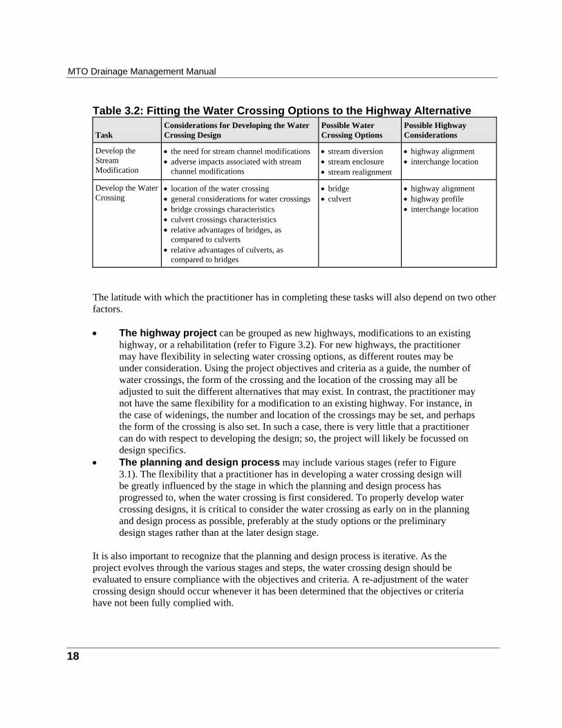
MTO Drainage Management Manual
18
Table 3.2: Fitting the Water Crossing Options to the Highway Alternative Task
Considerations for Developing the Water Crossing Design
Possible Water Crossing Options
Possible Highway Considerations
Develop the Stream Modification
• the need for stream channel modifications • adverse impacts associated with stream
channel modifications
• stream diversion • stream enclosure • stream realignment
• highway alignment • interchange location
Develop the Water Crossing
• location of the water crossing • general considerations for water crossings • bridge crossings characteristics • culvert crossings characteristics • relative advantages of bridges, as
compared to culverts • relative advantages of culverts, as
compared to bridges
• bridge • culvert
• highway alignment • highway profile • interchange location
The latitude with which the practitioner has in completing these tasks will also depend on two other factors. • The highway project can be grouped as new highways, modifications to an existing
highway, or a rehabilitation (refer to Figure 3.2). For new highways, the practitioner may have flexibility in selecting water crossing options, as different routes may be under consideration. Using the project objectives and criteria as a guide, the number of water crossings, the form of the crossing and the location of the crossing may all be adjusted to suit the different alternatives that may exist. In contrast, the practitioner may not have the same flexibility for a modification to an existing highway. For instance, in the case of widenings, the number and location of the crossings may be set, and perhaps the form of the crossing is also set. In such a case, there is very little that a practitioner can do with respect to developing the design; so, the project will likely be focussed on design specifics.
• The planning and design process may include various stages (refer to Figure 3.1). The flexibility that a practitioner has in developing a water crossing design will be greatly influenced by the stage in which the planning and design process has progressed to, when the water crossing is first considered. To properly develop water crossing designs, it is critical to consider the water crossing as early on in the planning and design process as possible, preferably at the study options or the preliminary design stages rather than at the later design stage.
It is also important to recognize that the planning and design process is iterative. As the project evolves through the various stages and steps, the water crossing design should be evaluated to ensure compliance with the objectives and criteria. A re-adjustment of the water crossing design should occur whenever it has been determined that the objectives or criteria have not been fully complied with.
Chapter 3: Developing and Evaluating Design Alternatives
19
The following subsections present the various considerations to be applied in developing the water crossing design: • the need for stream channel modifications; • adverse impacts associated with stream channel modifications; • location of the water crossing; • water crossings and the highway profile; • permanent erosion control measures; • structure performance; • soil and foundation considerations; • long term maintenance considerations; • factors to review when considering a bridge crossing; • factors to review when considering a culvert crossing; • relative advantages of bridges, as compared to culverts; • relative advantages of culverts, as compared to bridges; • locating fish habitat structures within a stream; and • consider data needs.
The Need for Stream Channel Modifications A thorough search for solutions that could avoid stream channel modifications is an important task and needs to be completed at the earliest possible stage of design. A thorough search should involve all affected professional disciplines, and internal and external offices and interests. If a stream modification is essential, it may take one of these forms: • several stream channels are diverted and combined to form a single stream channel; • a stream channel is realigned to avoid intersection with the highway; • a stream channel is modified to accommodate a bridge or culvert; • an entire stream channel is replaced with a culvert or sewer; or • modifications are required to mitigate an on-going erosion problem. Further variations of the above forms include lined stream channels, transitions (expansions, contractions, weirs and confluences), and energy dissipators (drop structures, stilling basins and baffled chutes). Guidance on the cases where stream channel modifications may be justified, provided there is no reasonable alternative such as relocating the highway, are as follows. • To reduce an excessive angle of skew (> 45°), which is both costly and structurally
undesirable. • To eliminate or reduce excessive encroachment of fill on the stream channel. This may
occur with high fills at skew crossings or where the channel is alongside the highway.
MTO Drainage Management Manual
20
• To eliminate a serious erosion problem at the highway or downstream property. • On rare occasions, to reduce the high water elevation at or upstream from a water crossing. • To reduce the number or length of water crossings at a complex interchange. • To reduce the number of crossings. For example, to eliminate the need for two
crossings where a tributary stream crosses the highway to enter the main stream a short distance downstream.
• To reduce the height of fill by moving the crossing away from a high valley side. • To reduce the number of crossings of a meandering stream flowing generally parallel to the
highway.
Adverse Impacts Associated with Stream Channel Modifications Stream channel modifications may impact the following (for more detail, refer to Table 2.1 and Table 2.2 in Chapter 2): • stream channel stability; • watershed hydrology; • stream channel hydraulics; • riparian land owner rights; • aquatic habitat; • terrestrial habitat; and • water quality.
Stream Channel Stability Modifications to stream channels may cause an impact to the overall stability of the stream channel. Impacts may include changes to shape, width, depth, length, sinuosity (i.e. stream channel meandering), and sediment loads. The impacts are the result of changes in the watershed geology, topography, soils, vegetation and precipitation. To minimize impacts, stream channel stability must be assessed before recommending any stream channel modification scheme . Considerable judgement must be used when designing, locating and sizing stable natural stream channels. Chapter 9, recommends ten steps for assessing stream channels. If stream channel stability is not assessed, some possible consequences are: • bed degradation and bank slumping upstream; • bed aggradation and increased channel shifts downstream; • destruction of favourable fish and wildlife habitat such as pools and shoals; • increased erosion of the remaining channel(s); • adverse effects on upstream and downstream channel conditions causing high channel
maintenance costs.
Chapter 3: Developing and Evaluating Design Alternatives
21
Watershed Hydrology
Any stream channel modification scheme may impact the hydrology of the watershed or catchment area. To assess any potential impacts to watershed hydrology, a hydrologic assessment should be completed for the existing case, as well as for all of the recommended schemes. The hydrologic assessment should include the following. • Ensure that all tributary areas are included and their boundaries are correctly determined. • Determine major and minor flow paths, and flow patterns which affect the design flow
calculations. • Determine the affect modification has on hydrograph timing, peak flow and shape. • Calculate design flows of all design frequencies including high flows, low flows and
fish passage flows, where applicable. It is increasingly important to consider low flows for environmental protection purposes such as erosion control, stormwater quality management, base flow management and wildlife habitat requirements. Refer to Appendix 3A for a discussion on hydrologic computational procedures.
Stream Channel Hydraulics Any stream channel modification scheme may impact the hydraulics of the stream channel. To assess any potential impacts to stream channel hydraulics, a hydraulic assessment should be completed for the existing case, as well as for all of the recommended schemes. The hydraulic assessment should include the following: • a stream channel flow analysis (velocities, water surface profiles,
subcritical/supercritical flow); • possible effects of the drainage works on the velocity frequency distribution for a flow
event (e.g. 2yr stream flow hydrograph); • effects on stream channel routing (stage versus storage and stage versus discharge); • effects on stream channel stability (tractive forces and scour potential); • the possibility of more severe ice jamming due to elimination of stream bends; • effects on the severity of ice jamming or flooding due to the elimination of relief flow; and • an assessment of regulatory flood levels for the existing case, and determine if any
potential impacts to the regulatory flood levels may be caused by the stream channel modification schemes.
Riparian Land Owner Rights The rights and uses of riparian land owners must be assessed when any water crossing or stream
channel modification scheme is being considered. Generally, a riparian land owner has the right to have water flow in its natural state with regard to both quantity and quality, and may put the water

MTO Drainage Management Manual
22
from the stream channel to any reasonable use. Any stream channel modification that may
increase or decrease the quantity or quality of water that traverses a riparian land owner's property, could prove to be an infringement upon their rights. Riparian land owner rights are generally dictated by common law precedents. Refer to Chapter 2, Appendix 2B for a detailed discussion on riparian land owner rights.
Aquatic Habitat Some potential impediments to aquatic habitat, fish passage and spawning areas that may result from improperly designed stream channel modification schemes, are as follows: • stream channel flow velocities are increased and flow depths are reduced when
steeper stream channel slopes and smoother lining materials are used; • natural fish resting areas are eliminated; • prolonged or short-term flooding is increased; • large artificial stream channel bed drops are created; • water temperature increases when vegetation adjacent to a watercourse is removed; • damage to downstream habitat caused by sedimentation of spawning and hatching grounds; • restrictions on fish passage where check dams or channel drops are used (alternatively,
a special provision, such as a fish ladder, could be included, although this would be costly);
• restrictions on fish passage if erosion protection (e.g. riprap) is not sufficiently imbedded into the stream bed; and
• increases in water temperature caused by the use of impervious linings (i.e. natural groundwater is reduced due to subsequent reductions in infiltration).
For details, refer to the MTO Environmental Manual, Fisheries
Terrestrial Habitats Stream channel modification schemes may affect: • trees, shrubs, grasses and legumes; • vegetation (lichens, mosses, etc.); • crops; • wildlife (mammals, reptiles, amphibians, etc.); • insects; and • birds (migratory and resident).
Water Quality Generally, a stream channel modification scheme may impact water quality by increasing water
Chapter 3: Developing and Evaluating Design Alternatives
23
temperatures or by increasing sediment loading.
Location of the Water Crossing Considerations for the location of water crossings include: • stream channel stability and self-adjustment; • crossings at aggrading and degrading channel; • crossings at alluvial fans and deltas; • crossings at braided channels; • crossings at a stream confluence; • local stream channel modifications; • crossing at wetlands and lakes; • possible problems with floating debris; • factors related to the water crossing and the highway; • external constraints; • navigation requirements; and • bridges on sag curves.
Stream Channel Stability and Self-adjustment One of the most important hydraulic factors governing the location of a water crossing is the stability of the stream channel. Chapter 9 provides a detailed discussion on stream channel stability. The following effects may influence the location and design of a water crossing. • If an erodible channel is constricted by a crossing, the bed will tend to scour. • If a channel is steepened by elimination of meanders etc., the channel will tend to
return to the flatter slope by degrading its bed. • When bank protection is used to prevent channel shifts at one location, erosion may be
accelerated elsewhere. • Erosion at one location in a channel is usually accompanied by deposition at another. • Over a period of many years, a channel may move back and forth several times over
the same area. • An increase of dominant discharge (e.g. due to diversion of flow from another basin) will
increase the channel depth and width.
Crossings at Aggrading and Degrading Channels Aggrading and degrading channel reaches are generally unstable and unpredictable and should be avoided wherever possible. Aggradation and degradation are discussed in Chapter 9.
MTO Drainage Management Manual
24
Crossings at Alluvial Fans and Deltas
Fans and deltas are discussed in more detail in Chapter 9. Crossings of fans should be avoided whenever possible. If a fan crossing is unavoidable, the same solution as for a braided channel (below) may be feasible. However, frequent excavation of the channel may be required to keep the water crossing waterway open. Delta crossings should be carefully located with the aid of air photos, site inspection and local information.
Crossings at Braided Channels Crossings of braided channels should be avoided if possible. Works to combine the sub-channels into a single channel should be considered if relocation is not possible.
Crossings at a Stream Confluence The stability of stream channels located near confluences is sometimes uncertain because material deposited by floods may cause channel shifts in either stream. Furthermore, the direction and distribution of the flow may vary with the discharge and stage of the stream, necessitating careful study to determine the best compromise for the structure location and highway alignment. The history of channel changes at such locations should be investigated.
Local Stream Channel Modifications Local stream channel modification may be required to accommodate the water crossing. Local modifications include the following: • straightening one stream channel bank or portions of the stream channel bed; • straightening both stream channel banks and bed; • widening the stream channel banks; • removing natural meanders; • dyking; • widening the stream channel banks; and • deepening, flattening or steepening the stream channel bed. Local modifications are usually composed of a number of drainage elements including lined stream channels, transitions (expansions, contractions, weirs and confluences) and energy dissipators (drop structures, stilling basins and baffled chutes). The previous section, Adverse Impacts Associated with Stream Channel Modifications, should be reviewed as the considerations listed within that section can also apply to local stream channel modifications. Consideration should also be given to natural channel techniques.

Chapter 3: Developing and Evaluating Design Alternatives
25
Crossing at Wetlands and Lakes
Crossings of provincially significant natural heritage features, lakes and tidal waters should be avoided if possible; however, if unavoidable, culverts, bridges and causeways should be designed to maintain the natural flow pattern. The use of equalizer culverts should be considered, and the creation of stagnant areas should be avoided. For additional guidance refer to the MTO Environmental Manual, Fisheries, and to the Provincial Policy Statements for Natural Heritage and Natural Hazards.
Possible Problems with Floating Debris • When selecting a crossing location, try to avoid a split channel or channel bars, as these
locations often capture floating debris. • Where floating debris may be severe, consideration of an alternate crossing location may
be advisable. If avoidance of the site is not practical, the design should consider measures to facilitate the passage of debris (e.g. the waterway opening configuration and size).
• Smaller culverts may create problems under some circumstances. • A bridge may be preferred over a culvert. A single span culvert may be suitable but it
likely will require further study to confirm its suitability. A multi-cell culvert should be avoided.
• For some cases, debris deflectors may be recommended to control debris flow.
Factors Related to the Water Crossing and the Highway • Foundation type and depth. • Limitations on grade imposed by adjacent properties, topography etc. • Construction cost. • Maintenance costs. • Class of highway; traffic volume, seasonal use only etc. • Safety of travelling public. Availability of relief flow in extreme floods.
External Constraints • Requirements of other users of the stream, including hydroelectric facilities and
water takings. • Existing and proposed flood control works. • Pipeline, sewer lines and other services.
MTO Drainage Management Manual
26
Navigation Requirements
Navigation requirements often constrain the height and width of a water crossing waterway opening. Bridge pier locations and alignments should account for navigation requirements.
Water Crossings on Sag Curves Water crossings should not be located at the bottom of sag curves, when possible, because of the high damage hazard in the event of an extreme flood. The possibility of surface ponding also exists.
Water Crossings and the Highway Profile Since it is impractical to design a water crossing to convey the maximum probable flood, a certain amount of risk in terms of structural failure, property damage and loss of life always exists. It is beyond the scope of this manual to present methods specific to risk and economic analysis. However, in general, it should be realized that a risk or economic analysis is a tool that can be used in making decisions as to the optimum water crossing design. The final decision should be based on the judgement of a team of professionals, and is often influenced by intangible factors to which a dollar value cannot be assigned. General considerations that apply to the water crossing and the highway are as follows: • freeboard; • relief flow; • relied flow and the highway profile; and • minor access under water crossings.
Freeboard In establishing the optimum highway profile, it is necessary to balance engineering and constructions costs against the need to keep the highway passable during flood events. The need to protect the water crossing and upstream property during floods must also be considered. This balance may be achieved by establishing the highway grade at a specified height (i.e. freeboard) above the high water elevation; or, by placing the highway grade at an elevation based on a predetermined frequency of overtopping. Guidance in establishing freeboard is provided below. • Standard freeboard in Ontario (see OHBDC, 1991) shall be not less than 1.0 m for freeways,
arterials and collectors, and 0.3 m for other highways such as township highways. • Freeboard is measured from the edge of through traffic lanes to the design high water
level (refer to OHBDC, 1991).
Chapter 3: Developing and Evaluating Design Alternatives
27
• The 1.0 m freeboard for freeways, arterials and collector highways includes an
allowance for a moderate amount of backwater. If the backwater is unusually large, the freeboard should be measured from the upstream high water elevation (including backwater).
• Freeboard for pedestrian or bicycle access paths (refer to OHBDC, 1991) passing through multi-use water crossings, shall not be less than: 1.0 m from the normal water level for spans of more that 6.0 m; and, 0.5 m from the normal water level for spans of 6.0 m or less.
Relief Flow Relief flow is flow that bypasses the main waterway opening by passing over the approach highway or through one or more relief structures. Generally, an embankment operates as a broad-crested weir when overtopped, and has a very large potential overflow capacity. This provides a "safety valve" against bridge or culvert failure in the event of an extreme flood. It also provides a means of reducing backwater during ice jams or extreme floods, and in some cases can permit a considerable reduction in costs. The principal disadvantage of relief overflow is the inconvenience and possible hazard to highway users. The most economical water crossing, where non-hydraulic conditions permit, is one at which: the normal design flood passes safely through the waterway opening without flooding the approach highway; and, an extreme flood (greatly exceeding the normal design flood) flows over the highway. This "relieves" the bridge or culvert and produces the following benefits and disadvantages. • Advantages of relief flow are listed below.
• As soon as flow over the highway commences, the flow velocity through the waterway opening remains steady, and the possibility of scour failure is reduced.
• Flow over the highway minimizes backwater and its effects on upstream properties. This may be particularly beneficial for the Hazel or Timmins Regulatory floods (i.e. the waterway opening may be designed for the normal design flood while the overall crossing, with relief flow, satisfies the Regulatory flood requirements).
• A washed-out highway (resulting from an extreme flood) may be brought back into service much more quickly and economically than a washed-out bridge or culvert.
• The size of flood that can accommodate relief flow over the highway, rather than through a relief structure, is unlimited.
• The availability of relief overflow can greatly reduce the upstream effects of a blockage to the main channel by ice or debris.
• If a bridge or culvert structure becomes inundated, relief overflow can reduce much of the lateral pressure and reduce the risk of failure.
• Disadvantages of relief flow are listed below.
• The principal disadvantages of flow over the highway are the inconvenience and possible risk to the highway user. Although the inconvenience of infrequent flooding
MTO Drainage Management Manual
28
of highways is generally accepted by the public, particularly on minor highways, traffic hazards on main highways during overflow periods should be minimized whenever possible by warning signs or highway closures. This may be difficult and sometimes impossible on small streams experiencing flash floods.
• Frequent overflow resulting from an excessively low approach grade may necessitate recurring repairs to the shoulders, fill and possibly the highway. These problems may be overcome by providing an appropriate freeboard, providing erosion protection, or, on existing highways, by raising the grade by a carefully selected amount. Infrequent repairs to the highway are usually acceptable and are quicker and less costly than repairs to washed out structures.
Relief Flow and the Highway Profile The elevation of the approach grade should be established by adding the specified freeboard to the design high water level. For hydraulic purposes, the optimum highway profile at a water crossing slopes down from the edge of a valley, across the stream and then levels off across the flood plain. This allows plenty of relief flow area, but also keeps the crossing clear of the high water elevation, and avoids the crest curve that would occur if the crossing were near the centre of the flood plain. Additional guidance on relief flow and the highway profile is provided below. • Make the relief flow section as long as practically possible. • Avoid locating a highway sag opposite a nearby downstream building that might be
damaged by concentrated overflow or by ice passing over the highway. • Locate the relief flow section well away from the water crossing(s) (e.g. 3 to 4 times
the water crossing height) so that the structure(s) will not be damaged in the event of a highway washout.
• Relief culverts may be advisable if the main water crossing is subject to blockage by ice or debris; or, if required for local drainage of a wide flood plain. Experience has shown that relief culverts are of limited value, except in rare circumstances.
• Where a large flow along the highway embankment is anticipated, the approach grade profile should parallel the flow line along the upstream face of the embankment. This applies mainly to a crossing skewed to the flood plain, and to a crossing at the apex of a meander.
Minor Access Routes under Water Crossings In addition to conveying flow, waterway openings may function as passages for pedestrians, motorized vehicles, wildlife or livestock provided that the waterway is appropriately designed. In these cases, consider the guidance provided below. • Ministry procedures should be followed when determining whether a multipurpose water
crossing is acceptable and how the costs should be shared.
Chapter 3: Developing and Evaluating Design Alternatives
29
• The cost savings should be weighed against the possible disadvantages of multiple
use, such as the potential hazards to people passing through the water crossing. Safety experts and local authorities should be consulted.
• Provision should be made for easy access to the water crossing. • Installations should be vandal proof, and lighting should be provided where necessary. • The freeboard of the pathway should be agreed upon by all concerned parties. • If the access route profile is placed too low, it may be liable to frequent erosion damage
and other maintenance problems (e.g. mud, ice, debris). On the other hand, if the access route profile is unnecessarily high, it may significantly reduce the waterway opening.
Permanent Erosion Control Measures Permanent remedial erosion measures are used to reduce or remedy existing stream channel erosion problems. Erosion problems include: • bank erosion (e.g. slumping, sloughing, undermining or undercutting) ; or • stream channel bed erosion (scour). Remedial measures include vegetation cover (i.e. soil bioengineering), lining treatments, retaining walls, bank drainage diversion, buffer strips, energy dissipators, drop structures, and culvert outlet and inlet treatments. The use of harder measures (e.g. drop structures, energy dissipators) should not be selected without considering softer measures (e.g. soil bio-engineering, natural channel techniques) first.
Structure Performance • It is good practice to monitor structure performance during or after large flows.
Performance analysis may reveal under or over-design, and may help to reveal widespread design practice problems (e.g. sometimes a culvert washout may have been caused by an extreme flow, well above the design flow, even though the culvert may have been adequately designed).
• Washouts may also result from lesser flows where there are design deficiencies, such as improperly designed spread footings or scour protection.
• Timely maintenance may reduce the need for costly repairs or replacement. Examples of problems to be identified early and corrected are undermining, distortion, inlet lifting, and obstruction by debris and erosion.
MTO Drainage Management Manual
30
Soil and Foundation Considerations
Soil and foundation considerations are the realm of soil and geotechnical engineers. A qualified geotechnical engineer should be consulted. Some soil and foundation considerations are presented to raise general awareness of soil engineering in water crossing design. • The potential for piping failure. • Evidence of groundwater problems. • Possible scour problems. • Uplift pressures. • Side slope stability.
Long Term Maintenance Considerations • Input from maintenance operators, especially when any new design approach or
technology is proposed (e.g. maintenance staff to form part of the design team). • Consider stream channel gradients: slopes that are flat could result in ponding and
excessive plant growth which could lead to reduced capacities and potential flooding. Also, very steep slopes could result in stream channel erosion and deposition, reducing stream channel capacities.
• Consider stream channel side slopes: steep side slopes could result in slumping which could block or obstruct flow.
• The provision for an access road (approximately 5 m wide) along the top of the stream channel for maintenance vehicles.
• Written instructions for maintenance should be prepared as part of the design for non-standard drainage facilities. Instructions should include the original design objectives, expected performance of the facilities, and the frequency and extent of maintenance and inspection procedures.
• Items in inspection reports that may be of interest to the designer generally include stream channel bed and bank erosion, and siltation; lining conditions; presence and condition of undergrowth; river aggregation/degradation; abnormal settlement; cracking or spalling of concrete; condition of concrete joints; abnormal foundation leakage; foundation undermining; and description of slide, sloughing and sudden subsistence.
Factors to Review When Considering a Bridge Crossing Option The considerations presented within this section are of a preliminary nature, and are more suited to any of the following scenarios: • drainage options are under development for a water crossing location; • the form of the water crossing (i.e. bridge or culvert), has not yet been determined;

Chapter 3: Developing and Evaluating Design Alternatives
31
• preliminary considerations are required to determine if a bridge crossing is a viable option;
or • considerations are required to develop a preliminary bridge layout and configuration. If more detail is required, refer to the section, Completing a Bridge Crossing.
Location and Alignment • If possible, locate the crossing on a stable reach of stream channel. • A relatively straight reach is preferred, but a suitable crossing may sometimes be found
at the apex of a stable bend impinging on the valley side. • Care should be taken that the cost of relocating the proposed highway to a stable reach
does not outweigh the cost of providing training works on an unstable channel section. • Avoid obvious problem areas such as areas prone to landslip, which may usually be
identified from air photos. • On highly meandering channels, locate the highway such that the upstream channel
loop is far enough away that it will not fold against the highway in the foreseeable future. Relocation of the highway or channel should be considered if necessary to avoid future remedial costs that may be much higher than the cost of relocation.
• Align the structure opening with potential high-velocity flows from an upstream structure or dam spillway. Conversely, align the structure such that the outlet flow will not adversely affect downstream highways, railways or other property. These remarks apply also to relief structures.
• Consider the width of fill at skewed crossings to avoid encroachment on the channel. Take possible future widening of the highway into account.
• If subsoil materials are highly variable (e.g. bedrock on one side of the stream and deep muskeg on the other), select the optimum location based on the consideration of both foundation and hydraulic requirements.
Pier and Abutment Location and Alignment • Construction of piers on spread footings in erodible channels introduces the
possibility of a future scour failure. Therefore, subject to structural and cost considerations, the use of piers on spread footings in such channels, should be minimized or avoided altogether. Piers should also be avoided in very steep, fast-flowing streams transporting gravel or boulders.
• In bridge extensions, avoid placing piers opposite the upstream openings or constructing a single-span extension upstream from multiple spans.
• Piers and abutments should normally be aligned with the main channel. If the flow alignment differs considerably between low and high stages, or the future alignment is uncertain due to probable channel shifts, circular pier shafts should be considered.
• Training works may be needed if channel shifting is a serious problem.
MTO Drainage Management Manual
32
• Abutments on a straight stable channel, are normally placed equidistant from the stream banks. • A closed abutment on the outside of a stream bend should be placed at or back from the
toe of bank, which should be protected against erosion. Any fill slope should be aligned with the toe of the stream bank.
• Piers should be aligned to all flows if possible. Circular pier shafts may be used where the direction of flow varies considerably from low to high stages. Skews should normally not exceed 45° or preferably less.
• If the channel is curved, the effect of the structure outlet velocity on the outer downstream bank should be considered when selecting the skew angle for the piers.
• Debris accumulations preventing fish passage, should be avoided by proper spacing and placement of bridge piers, and by providing vertical clearance above the design flood.
• Full consideration should be given to the potentially harmful effects of stream diversions, which should be constructed only where a reasonable alternative is not feasible (refer to the section, Adverse Impacts Associated With Stream Channel Modifications).
Dual Parallel Bridges • The backwater produced by a parallel pair of identical bridges is larger than that for a single
bridge; but, not as much as would result if the bridges were considered separately. • If the bridges are more than one bridge opening width apart, backwater should be
calculated as if they were single bridges.
Factors to Review When Considering a Culvert Crossing Option The considerations presented within this section are of a preliminary nature, and are more suited to any of the following scenarios: • drainage options are under development for a water crossing location; • the form of the water crossing (i.e. bridge or culvert), has not yet been determined; • preliminary considerations are required to determine if a culvert crossing is a viable
option; or • considerations are required to develop a preliminary culvert layout and configuration. If more detail is required, refer to the section, Completing a Culvert Crossing.
Location and Alignment • Some of the considerations for bridge location and alignment may apply to culvert crossings. • Significant stream channel modifications that are needed to accommodate a culvert, should
Chapter 3: Developing and Evaluating Design Alternatives
33
be avoided, wherever possible. • A straight culvert located on, and aligned with, the natural stream is desirable to
avoid uneven scour of open footing culverts and uneven silting of multi-barrel culverts, and to reduce head losses if velocities are high.
• If it is necessary to break the culvert alignment in order to conform with the natural stream alignment, the culvert should be curved in plan or should have angular bends not exceeding 15 degrees at intervals of 15 m. In such cases the possibility of debris blockage should be considered.
• To avoid silting of the barrel on the inside of the bend, it is desirable that mutli-barrel culverts be straight and aligned with the upstream segment of the stream.
• The selection of culvert location and alignment at difficult sites is best done in the field with the aid of air photos and survey plans, and should take account of the width of fill and of any future widening.
• Where flow from a roadside ditch (e.g. on a steep grade) is to be discharged into the culvert, the culvert entrance geometry should be checked to ensure that the flow will not over-shoot the culvert entrance.
Culvert Profile • Slopes of culverts on uniform grade are usually made parallel to the natural slope unless the
gradient is almost flat, in which case the culvert grade may be level. • Slopes can be modified to improve culvert performance or reduce velocities. In such
cases, care should be taken to avoid: aggradation or degradation of the upstream segment of the stream; erosion of the downstream fill or channel; or, loss of aquatic habitat.
Culvert Embedment • Common practice is to place the floor of a closed invert culvert slightly below the natural
stream bed in order to:
• permit future deepening of the stream; • reduce the possibility of undermining; or • provide for the passage of fish.
• In deciding on the invert, or depth of embedment, it is important to consider its effect on
the future stability of the stream, upstream or downstream of the crossing. • Embedding the culvert can create or perpetuate upstream degradation. In such cases a drop
structure may be required. “Deep” embedments should be artificially filled with gravel. • Experience has shown that deposits in properly embedded culverts are normally cleaned
out by moderate floods. • On aggrading streams, the culvert invert should be placed no lower that the stream bed.
MTO Drainage Management Manual
34
Additional vertical clearance should be considered to allow for future build-up of the bed material.
Culvert Length • The length of a culvert should be sufficient to keep the fill from obstructing the
waterway. Culvert barrels may be shorter when wingwalls or headwalls are used to retain fill.
• To avoid uplift pressures or fish passage problems, the length should be minimized. If extra length is required for future widening, uplift pressures should be checked and appropriately addressed.
• If a culvert does protrude from an embankment, consideration should also be given to the potential for bank erosion, and safety with regards to errant vehicles.
Relative Advantages of Bridges, As Compared to Culverts • Bridges may be more economical than culverts with high fills. • Bridges present less disruption to fish, wildlife, wetlands and aquatic environment. • Bridges permit easy access along valley park systems, thereby eliminating a traffic
hazard for park users at highway crossings (i.e. multi-use crossings). • Backwater at bridges during major floods is normally less. • Bridges are usually less susceptible to blockage by debris or ice. • Bridges may be designed to present less obstruction to navigation. • Bridges generally cause less disruption to the environment during construction. • Widening of the bridge (parallel to stream) does not significantly increase backwater. • The extensive lengthening of culverts to accommodate future highway widenings, may
increase backwater. • The bridge channel invert may be lowered in the future with no great problem, subject
to scour protection and foundation design (may not be viable for spread footing piers). The future lowering of the channel invert is limited at closed invert culverts and further deepening could be costly.
• The highway surface, at culverts under shallow fills, may require frequent maintenance because of differential frost heave and settlement.
• Open footing culverts are often susceptible to scour failure. • Improperly designed or constructed steel culverts are prone to a variety of major problems,
including uplift and distortion. • Improperly designed projecting culvert ends can present a serious hazard to vehicles
running off the highway. • Some culvert types are susceptible to abrasion and corrosion, reducing their service life. • Rigid culverts are susceptible to separation at the joints, possibly leading to undermining and
failure. • Larger head differentials across culvert embankments are conducive to failure caused by
Chapter 3: Developing and Evaluating Design Alternatives
35
excessive seepage and piping through fill.
Relative Advantages of Culverts, As Compared to Bridges • The highway surface at culverts requires less maintenance (except possibly under very
shallow fills). Maintenance of the bridge deck surfaces is often costly and difficult. • Closed invert culverts generally require a smaller waterway opening. • For properly designed culverts, the risk of scour failure of a closed invert culvert is
negligible. • The highway surface at culverts is not subject to the local icing often experienced on
bridge decks, which can create a traffic hazard. • The highway grade at a culvert can be raised in future. The future raising of the
highway grade may be difficult or impossible for some types of bridge structures (i.e. the bridge may have to be replaced).
• Culverts require less structural maintenance than bridges. • Hydraulic capacity of culverts can sometimes be increased by adding an improved inlet. • Differential settlement between the approach fill and the structure often causes a bump at
the ends of the bridge deck. • The bridge superstructure is susceptible to damage or failure due to buoyancy, drag and
impact forces during extreme floods. • Bridge deck drainage systems often create significant maintenance problems. • Spill through bridge fill slopes are susceptible to erosion damage.
Locating Fish Habitat Structures within a Stream In parallel with the hydraulic design of a water crossing, the fish biologist and other allied professionals will investigate the biological conditions and other conditions of the site, and use their expertise and applicable reference materials to establish the need for, and the design of, fish habitat structures (refer to the MTO Environmental Manual, Fisheries). The relative suitability of any potential location selected to house a fish habitat structure should be examined as part of the hydraulic design of the water crossing and will dependent on the factors presented below. • The geomorphic characteristics of the stream, and the relative stability, or instability, of
the stream can be estimated using the ten step procedure that is presented in Chapter 9. • Stream erosion (i.e. scour), and sediment transport and deposition, may be detrimental to
the fish habitat structures. Conversely, the structures may alter the erosion and sedimentation processes of the stream. Methods presented in Chapter 9 can be used to investigate if erosion or sedimentation will be a problem within the stream reach.
• Ensure that hydraulic processes within the stream will not impact the fish habitat structure. Preferably, habitat structures would be located on a straight stretch of the stream (a river bend is not considered to be a desirable location). Habitat structures should be designed to
MTO Drainage Management Manual
36
withstand the design flow velocities and provide little obstruction to flow. • If habitat structures are proposed to be near a bridge or culvert, potential adverse impacts
on the structural integrity and hydraulic performance of the bridge or culvert should be investigated.
• Structures are placed at irregular intervals and in low flow areas. • Consider construction limitations and post construction monitoring.
Consider Data Needs For completeness, a brief discussion on data needs associated with water crossings is presented within the following section. Additional data needs for detail design are presented in Chapter 5.
Proposed Crossing Information on the proposed crossing should be based on a field inspection and on interviews with local residents, municipal officials, maintenance personnel, government agencies, and any other available sources. The following information should be considered: • details of properties or structures which may be affected by the proposed crossing (e.g.
main floor elevation, elevations of well tops upstream of highways, etc.); • past debris or ice jamming events; • existing or potential icing problems; • existing bank erosion and deposition; • stream bed degradation; • past or possible future channel alterations; • stream bed material and rock outcrops; • past flood elevations (with information on abnormal events); • controls such as lakes, waterfalls, dams or larger streams; • alternative locations for new crossings; • description of channel and flood plain roughness, required to estimate roughness
coefficient(s) (including sketch and/or photograph); and • photographs of existing erosion, properties close to the flood level, and any other special
features (may be valuable both for design purposes and in the event of future claims).
Existing Structures In the design of a new structure, it is often beneficial to consider the hydraulic performance history
of existing water crossings. The age of an existing structure and its performance over time is one of the best means of determining its adequacy (e.g. for a fifty year old structure, there is a 64% probability that it has experienced a flow exceeding the 50 year flow). Any information should be

Chapter 3: Developing and Evaluating Design Alternatives
37
based on inspections and on interviews with residents, maintenance staff and other sources. The following site information should be recorded where relevant: • location and type of structure; • estimated age; • dimensions of waterway (normal to flow); • high water levels upstream and downstream; • ice or debris problems; • relief flow over highway; • any remediation of past problems; • downstream controls affecting flow and tailwater levels at the water crossing; • bed material; • hydraulic damage or repairs to the water crossing; • excessive erosion; • past washouts of structure or highway; • relevant history of structure, such as past channel deepening, degradation or dam washouts; • the capacity of the water crossing; • other relevant details including special inlets, outlets and erosion control structures; and • photographs of relevant features.
Local Information The importance of interviewing local MTO maintenance staff, local residents and municipal officials, conservation authorities and MNR staff, and other knowledgeable people, cannot be over stressed; since, they will, in many cases, be able to supply information unobtainable in any other way. High water levels in particular should be ascertained or checked from these sources.
Soils Information The designer should know the nature of the subsoil material underlying the stream bed unless it is obvious that it is sound bedrock, or other material which will create no problem. Organic material should be given special attention, and a sound knowledge of the scourability of the soil is essential. Detailed foundation investigations should be carried out for bridges and large culverts, unless it is certain they will be founded on sound bedrock. A geotechnical specialist will be able to provide guidance for specific data needs.
Fish Migration Data A fish biologist should be consulted for specific data needs. Also, refer to the MTO Environmental Manual, Fisheries). Useful fish migration data are:

MTO Drainage Management Manual
38
• species of migrating fish, size and swimming speed; • locations of spawning beds, rearing habitat, and food-producing areas upstream and
downstream from the site; • description of fish habitat at the proposed crossing; • dates of start, peak and end of migration; • average flow depth and width during migration; and • average date of maximum annual flood.
39
Completing a Bridge Crossing Design
The design of a bridge structure must integrate structural and foundation considerations with the hydraulic considerations of the bridge waterway opening. This section will present the hydraulic considerations for bridge crossings, under the following headings: • considerations at this stage of the bridge crossing design; • applicable hydrologic methods for bridge crossing design; • applicable hydraulic methods for bridge crossing design; and • information sources and working details for bridge crossing design. In conjunction with this section, review the section Factors to Review When Considering a Bridge Crossing Option.
Considerations at this Stage of the Bridge Crossing Design Design considerations for bridge crossings include the following: • hydraulic problems at bridge crossings; • span arrangement; • pier details; • abutments; • superstructures; and • soffit elevation.
Hydraulic Problems At Bridge Crossings Significant problems that may be experienced at bridge crossings are as follows. • Bridge failures or structural damage caused by undermining of the foundation by scour,
degradation or dredging. • Partial or complete washing out of the approach embankment by overflow. • Dislodging failures or damage to bridge superstructures by the action of buoyancy,
flowing water, ice or debris (refer to OHBDC, 1991). • Bending of piles by the impact of ice or debris. • Erosion of fill in spill through bridge openings. • Increased flooding of upstream property due to bridge backwater. • Increased erosion of downstream banks due to concentration of the flow from the flood
MTO Drainage Management Manual
40
plain. • Debris or ice jamming caused by low soffits or excessively short spans. • Erosion of the approach embankment due to shifting of the stream channel. • Problems caused by inadequate deck drainage systems.
Span Arrangement The following factors should be considered in selecting a span arrangement, bearing in mind structural limitations and requirements. Care must be taken that the extra cost of meeting horizontal clearance requirements is fully justified by the benefits received, bearing in mind that an increase of span may affect the type of bridge, and therefore the cost. • In channels subject to severe ice jamming the span lengths should be as large as is
economically feasible. • Short spans (e.g. 5 m or less) should be avoided on streams carrying medium or large
debris. The use of larger spans may also discourage beavers building dams at bridges. • For navigable streams, requirements of the authority having navigational jurisdiction
over the stream should be ascertained.
Pier Details Careful attention to pier design will minimize the danger of scour and other hydraulic problems. The following points should be considered as well as those relating to scour. • Preliminary pier locations may need adjustment after the foundation investigation has been
received. • A semi-circular vertical pier nose is reported to be the best for minimizing debris
problems. A slight positive slope on the pier nose is also acceptable. • Where large flows enter the bridge opening from the flood plain, end piers should be
kept well away from abutments and fill slopes. This approach can avoid a concentration of scour.
• Piles should be protected against impact by ice floes or heavy debris. • Pier shaft and footing widths (including sheet piles) should be minimized. • Scour protection for pier and abutment foundations should be considered.
Abutments • Abutments should normally be aligned with the flood flow and foundations should
have ample scour protection.
Chapter 3: Developing and Evaluating Design Alternatives
41
Superstructures
• At many crossings there is a definite probability or risk that the superstructure will be
submerged at some time in its lifetime. For superstructures liable to submergence, explicit design features are required to resist transverse motion (refer to OHBDC, 1991).
• The provision for a suitable clearance from the bridge soffit to the design high water elevation or ice jam level, is important. However, there is often a limit on how high the bridge may be constructed. For instance, limits include cost (i.e. soffit elevation has a direct effect on cost) and the need to keep the approach grade low enough to provide for relief overflow.
• A remedial measure that can be considered for small bridges is to secure the structure to nearby trees with wire cables.
Soffit Elevation • The height of a bridge relative to flood and ice jam levels is important for safeguarding the
superstructure against various forms of damage, minimizing the impacts of the bridge on backwater and navigation; and maximizing the amount of relief flow over the approach grade.
• Where backwater is critical, consideration should be given to maximizing relief overflow. • At many crossings the soffit elevation may be based on the minimum vertical clearances,
but at others the hydraulic requirements may have to be overruled by less flexible factors such as site topography, highway geometry, elevations of adjacent properties or foundation constraints.
• Consider increased clearance where ice or debris conditions are exceptionally severe, and for long spans, especially of light construction.
• Consider reduced clearance:
• for a curved soffit (e.g. concrete arch or rigid frame) where there is no danger of damage from water, ice or debris;
• at sites where the height of the approach grade is limited by subsoil conditions; • on seasonal highways or highways having an exceptionally low traffic volume; • where the lowest point of the soffit is well out of the main channel; and • at low-water bridges.
Applicable Hydrologic Methods for Bridge Crossing Design • For a brief discussion on the application of hydrologic computational procedures, refer to
Appendix 3A. For a detailed discussion, refer to Chapter 8. • Stream flow rates can be determined using the methods in Appendix 3A. • Peak flow methods, such as rational or modified index flow method can be used for initial or
MTO Drainage Management Manual
42
preliminary bridge opening sizing (i.e. to determine slope, cross-sectional area or lining). • Peak flow methods are appropriate for final design, but they must be applicable. • For complex situations, where a more accurate assessment of flow is needed, hydrographic
methods may be more appropriate. • In finalizing a bridge design, a hydraulic backwater assessment should be completed.
Generally, such an assessment will include a regulatory flood line calculation which will require that a hydrographic method be used to determine the peak flow input.
• Hydrograph storage routing can be completed at the final design stage to check for any attenuation effects on hydrograph characteristics such as peak flow, peak flow timing, and total duration of the hydrograph.
• Computer programs that can be used to determine runoff hydrographs and also complete hydrograph routing, are presented in Appendix 3A, Table 3A.3.
Applicable Hydraulic Methods for Bridge Crossing Design • For a brief discussion on the application of hydraulic computational procedures, refer to
Appendix 3B. For a detailed discussion, refer to Chapter 8. • Preliminary sizing of the waterway opening can be completed using methodology presented
in Appendix 3B. At final design, the culvert must be sized using exact information. • Vertical drops, erosion protection, scour protection or flow control structures can be
sized using the method presented in Chapter 5. • Any design of a stream modification must be checked with a detailed backwater
assessment that will incorporate any changes to stream channel and profile configurations, as well as any vertical drops, erosion protection, scour protection or flow control structures that may be included as part of the design.
• The appropriate computational backwater method will depend on the complexity of the design as well as the flow regime. Refer to Appendix 3B for a discussion on different applicable methods.
• Computer programs that can be used for hydraulic computations, are presented in Appendix 3B, Table 3B.1.
Information Sources and Working Details for Bridge Crossing Design In the design of bridge crossings, the practitioner will: • ensure relevant design considerations are incorporated into the design details; • use appropriate computational methods to evaluate the performance of the proposed design;
and • ensure that sufficient and appropriate data and assumptions are used.
This can be accomplished by applying the procedures presented in Chapter 5 in conjunction with
Chapter 3: Developing and Evaluating Design Alternatives
43
the previous sections on design considerations and computational procedures. More specifically, Chapter 5 provides details on the design of the following items: • flow conveyance an backwater; • river ice; • scour; • fish passage; • debris flow; • energy dissipation; • erodible channels; • stream channel lining material; and • the hydraulic design of fish habitat structures.
44
Completing a Culvert Crossing Design
The design of a culvert crossing structure must integrate structural and foundation considerations with the hydraulic considerations of the culvert opening. This section will present the hydraulic considerations for culvert crossings, under the following headings: • considerations at this stage of the culvert crossing design; • applicable hydrologic methods for culvert crossing design; • applicable hydraulic methods for culvert crossing design; and • information sources and working details for culvert crossing design. In conjunction with this section, review the section, Factors to Review When Considering a Culvert Crossing.
Considerations at this Stage of the Culvert Crossing Design The design considerations for culvert crossings include the following: • common hydraulic problems; • open footing versus closed invert culverts; • culvert material; • culvert shape; • multi-barrel culverts; • culvert profile; • culvert length; • culvert safety concerns; • fish passage design flow; • clay seals; and • other considerations.
Common Hydraulic Problems The designer should be aware of the types of problems that culverts are susceptible to, in order to minimize their occurrence in the future. The more common or serious problems are listed below: • overtopping and washing out of embankments; • scour at open footing culverts; • undermining of footings due to channel degradation;

Chapter 3: Developing and Evaluating Design Alternatives
45
• undermining due to artificial deepening of channel; • erosion of fill at inlet; • uplift of corrugated steel culvert inlets; • invert buckling of corrugated steel culvert; • outlet erosion; • debris blockages; • culvert icing; and • washouts resulting from percolation through fill.
Open Footing Versus Closed Invert Culverts • A disadvantage of open footings is that the size of culvert required for safe performance is
frequently larger than the equivalently sized closed invert culvert. Open footing culverts are also vulnerable to failure caused by scour, degradation or artificial deepening.
• The use of open footing culverts is recommended at sites where: future deepening is uncertain, such as on some municipal drains or urban drainage schemes; and on fish migration routes where the increased roughness of a natural stone bed is desirable for reducing the flow velocity. However, in the latter case, the same effect may sometimes be achieved in closed invert culverts by placing a layer of stone or gabions, provided that the material will not be moved by the design flood.
• Other than in the circumstances outlined above, open footing culverts should be used only on bedrock or equally scour-resistant material, or if protected by a permanent floor slab with cutoffs.
Culvert Material The choice of material for culverts depends on the initial cost, service life, maintenance costs, hydraulic performance, ease of construction, salvageability, structural strength, fish passage requirements, and other factors. Materials for culvert construction include corrugated steel, concrete, and plastic (where the choice of culvert material is not critical to the hydraulic design, the Ministry may allow a contractor to bid on alternative materials). Some of the factors to be considered in making a suitable choice are as follows. • Steel and plastic have the advantage of simpler and quicker construction, particularly in
remote areas, while steel has the added advantage of often being at least partly salvageable after being washed out.
• A well designed concrete box culvert is extremely durable under a wide range of conditions. • Precast concrete and smooth-walled plastic pipes provide more efficient inlets than do sharp
edged inlets on metal culverts. • The greater roughness of corrugated interiors may be an advantage for fish passage and for
other situations where barrel or outlet velocities must be reduced.
MTO Drainage Management Manual
46
Culvert Shape
• Cross-sectional shape will depend on the height of fill and depth of flow. • Circular pipes are structurally efficient, readily available, cost somewhat less than other
shapes having the same capacity, and may be somewhat less susceptible to total blockage by icing due to their greater height.
• Corrugated steel pipe arches are useful under low highway grades. • Horizontal ellipses are also useful at low profile sites, and when properly designed are
structurally stronger than pipe arches. • The advantage of rectangular shapes is that their dimensions (i.e. width and depth) can be
varied to suit a wide range of site conditions. However, precast concrete culverts may be more preferable in remote areas, or where the time available for construction is limited.
• Arches of reinforce concrete or corrugate steel are useful for low-profile situations, shallow flows and fish passage; but, they require scour protection (i.e. in erodible soils) and better than average foundation support.
Multi-Barrel Culverts • In general, the use of multi-barrel culverts should be approached with caution. • Culverts having more than one barrel or cell may be necessary for wide streams having
relatively low depths of flow, and for shallow fills. • Multi-barrel culverts are also useful when fish passage has to be provided. In such cases,
only one barrel needs to meet the fish passage requirements. This barrel may be smaller and at a lower elevation; or, alternatively, a transverse sill may be provided across the other barrels to concentrate low flows through the single barrel.
• Where passage is to be provided for humans, cattle, or other animals, one barrel should be place at a slightly higher elevation so that the invert will remain dry for most of the year.
• On debris carrying streams, multi-barrel culverts are more susceptible to blockage. • On curved stream alignments, the inner barrel is more prone to silt deposition.
Culvert Profile • The selection of a suitable profile and depth of embedment for a culvert may be influenced
by the following considerations:
• natural slope of the stream; • requirements for improved inlet design; • barrel and outlet velocities; • future deepening of municipal drains; • stream bed degradation or aggradation; • fish passage;
Chapter 3: Developing and Evaluating Design Alternatives
47
• differential settlement of the culvert; • undermining of the culvert ends; and • deposition of sediment inside the culvert.
• Flexible culverts on compressible soils, especially under high fills, should be longitudinally
cambered to overcome the effects of differential settlement.
Culvert Length • The length of a culvert should be sufficient to keep the fill from obstructing the waterway. • Excess length should be minimized to avoid fish passage problems, or uplift pressures that
may lead to failures. If extra length is required to accommodate future widenings, uplift pressures should be checked.
Culvert Safety Concerns • Culvert ends projecting from fill slopes may be a hazard to vehicles that run off the road.
Culvert ends may be mitred to match the fill slope or shaped to reduce the hazard to vehicles running off the road.
• In urban areas, culverts with significant depth should be fenced around the wingwalls and headwall to reduce the risk of people falling over.
• Grates may be installed to keep children from entering the culvert, and large drops in the stream or culvert bed should be avoided. A grate should only be specified after consideration of all possible negative effects, such as maintenance requirements or possible blockage of the waterway due to debris accumulation.
Fish Passage Design Flow Culverts on fish migration routes should permit the passage of fish during flow conditions likely to prevail at the time of migration.
Clay Seals For sites where a significant head differential may exist, a means of reducing the likelihood of piping is to incorporate an impermeable clay seal on the upstream side of the embankments (refer to Chapter 5).
MTO Drainage Management Manual
48
Other Considerations
Other design considerations are presented in Chapter 5. These include: • tailwater level; • improved culvert inlet design; • culvert end treatment; and • embankment fills adjacent to culverts.
Applicable Hydrologic Methods for Culvert Crossing Design • For a brief discussion on the application of hydrologic computational procedures, refer to
Appendix 3A. For a detailed discussion, refer to Chapter 8. • Steam flow rates can be determined using the methods in Appendix 3A. • Peak flow methods, such as rational or modified index flow method can be used for initial or
preliminary culvert sizing (ie. slope, cross-sectional area or lining). • Peak flow methods are appropriate for final design, but they must be applicable . • For complex situations, where a more accurate assessment of flow is needed, hydrographic
methods may be more appropriate. • In finalizing a culvert design, a hydraulic backwater assessment should be completed.
Generally, such an assessment will include a regulatory flood line calculation which will require that a hydrographic method be used to determine the peak flow input.
• Hydrograph storage routing can be completed at the final design stage to check for any attenuation effects on hydrograph characteristics such as peak flow, peak flow timing, and total duration of the hydrograph.
• Computer programs that can be used to determine runoff hydrographs and also complete hydrograph routing, are presented in Appendix 3A, Table 3A.3.
Applicable Hydraulic Methods for Culvert Crossing Design • For a brief discussion on the application of hydraulic computational procedures, refer to
Appendix 3B. For a detailed discussion, refer to Chapter 8. • Inlet and outlet control should always be checked to determine the governing situation.
For initial or preliminary sizing, assumptions can be made to simplify the calculation. At final design, the culvert must be sized using exact information.
• Vertical drops, erosion protection, scour protection or flow control structures can be sized using the method presented in Chapter 5.
• Any design must be checked with a detailed backwater assessment that will incorporate any changes to stream channel and profile configurations, as well as any vertical drops, erosion protection, scour protection or flow control structures that may be included as part of the design.

Chapter 3: Developing and Evaluating Design Alternatives
49
• The appropriate computational backwater method will depend on the complexity of the
design as well as the flow regime. Refer Appendix 3B for a discussion on different applicable methods.
• Computer programs that can be used for hydraulic computations, are presented in Appendix 3B, Table 3B.1.
Information Sources and Working Details for Culvert Crossing Design In the design of culvert crossings, the practitioner will: • ensure relevant design considerations are incorporated into the design details; • use appropriate computational methods to evaluate the performance of the proposed design;
and • ensure that sufficient and appropriate data and assumptions are used. This can be accomplished by applying the procedures presented in Chapter 5 in conjunction with the previous sections on design considerations and computational procedures. More specifically, Chapter 5 provides details on the following items: • flow through culverts; • river ice; • scour; • fish passage; • debris flow; • energy dissipation;. • erodible stream channels; • stream channel lining material; and • hydraulic design of fish habitat structures.
50
Completing a Stream Channel Modification Design
Avoiding stream channel modifications is the only sure way to minimize potential impacts and future problems. A thorough search for highway alternatives or options that can avoid or minimize stream channel modification, is an important task and should be done as early in the planning or design stage as possible. These issues are discussed in The Need for Stream Modifications and Adverse Impacts Associated with Stream Modifications, which should be reviewed in conjunction with this section. Traditionally, any stream channel modification scheme may increase the hydraulic efficiency by straightening, widening, or channelizing the existing stream channel. In highway design, stream channel modification will be required in the following scenarios: • several stream channels are diverted and combined to form a single stream channel; • a stream channel is realigned to avoid intersection with the highway; • a stream channel is modified to accommodate a bridge or culvert; • an entire stream channel segment is replaced with a culvert or storm sewer; or • modifications are required to mitigate an on-going erosion problem. The discussion in this section will focus on the design considerations for stream modifications. This will be covered under the following headings: • considerations at this stage of the stream modification design; • applicable hydrologic methods for stream modification design; • applicable hydraulic methods for stream modification design; and • info sources and working details for stream modification design.
Considerations at this Stage of the Stream Modification Design The design components associated with stream channel modifications are covered in Chapter 5. The main considerations are summarized here for convenience. • Any stream channel modification scheme should consider costs:
• construction and long term maintenance costs; • long term costs to remedy potential environmental impacts; and • the relative risks and costs associated with future damages that could result from legal
action brought forth by a riparian owner. • Other professional disciplines, internal and external, should be consulted.
Chapter 3: Developing and Evaluating Design Alternatives
51
• Storm sewer or highway ditch inlet and outlet locations should be located. • Any realigned stream channel segment should be reasonably compatible with the natural
flood flow pattern. • The natural character of the stream and its surroundings should be preserved. • Velocities in the channel and its vicinity should be limited, where necessary, by the
provision of check dams or other means, to those allowable for the natural bed and banks. Alternatively, erosion control measures should be provided at critical points.
• Hydraulic calculations and erosion controls (temporary and permanent) should take into account roughness coefficients applicable to conditions both immediately after construction and after the channel has become vegetated and stabilized.
• Side slopes should be appropriate for the bank materials and groundwater conditions. • Special provision for fish habitat should be made on gravel streams and others containing
valuable fish resources. • The diversion ends should be aligned so as to not adversely affect the upstream or
downstream channel or adjacent property. • Construction should be timed so as to avoid spawning periods. • Radii of bends should approximate those of the original channel. • The possibility of non-uniform flow in a short diversion should be considered. • The use of pilot cuts is not recommended. (These are small artificial meander cutoffs that
rely on the river flow to enlarge them to their ultimate size). They can have serious environmental effects arising from erosion and sedimentation.
Applicable Hydrologic Methods for Stream Modification Design • For a brief discussion on the application of hydrologic computational procedures, refer to
Appendix 3A. For a detailed discussion, refer to Chapter 8. • Steam flow rates can be determined using the methods in Appendix 3A. • Peak flow methods, such as rational or modified index flow method can be used as input to
an appropriate hydraulic method for preliminary stream channel modification sizing (i.e. slope, cross-sectional area or lining).
• In finalizing a stream channel modification design, a hydraulic backwater assessment should be completed. Generally, such an assessment will include a regulatory flood line calculation which will require that a hydrographic method be used to determine the peak flow input.
• Another hydrologic consideration in stream channel modification design is hydrograph routing. Hydrograph routing should be completed at the design stage to check for the effects of the proposed stream channel modification on hydrograph characteristics such as peak flow, peak flow timing, and total duration of the hydrograph.
• Computer programs that can be used to determine runoff hydrographs and also complete hydrograph routing, are presented in Appendix 3A, Table 3A.3.
MTO Drainage Management Manual
52
Applicable Hydraulic Methods for Stream Modification Design
• For a brief discussion on the application of hydraulic computational procedures, refer to
Appendix 3B. For a detailed discussion, refer to Chapter 8. • Manning equation or a simple standard step method application are quick and efficient ways
to complete preliminary sizing of stream channel modifications. Refer to Appendix 3B. • Vertical drops, erosion protection, or scour protection can be sized using the methods
presented in Chapter 5. • Supercritical conditions should be checked. • Any design of a stream channel modification must be checked with a detailed backwater
assessment that will incorporate any changes to stream channel and profile configurations, as well as any vertical drops, erosion protection, scour protection or flow control structures that may be included as part of the design.
• The stage-storage relationship for the modified stream channel and flood plain should be similar to the stage-storage relationship that exists for the natural conditions.
• The appropriate computational backwater method will depend on the complexity of the design as well as the flow regime. Refer to Appendix 3B, for a discussion on different applicable methods.
• Computer programs that can be used for hydraulics computations, are presented in Appendix 3B, Table 3B.1.
Information Sources and Working Details for Stream Channel Modification Design In the design of stream channel modifications, the practitioner will: • ensure relevant design considerations are incorporated into the design details; • use appropriate computational methods to evaluate the performance of the proposed design;
and • ensure that sufficient and appropriate data and assumptions are used. This can be accomplished by applying the procedures presented in Chapter 5 in conjunction with the previous sections on design considerations and computational procedures. More specifically, Chapter 5 provides details on the design of the following items: • remedial erosion control works; • suitable stream channel sections; • type of lining material, vegetative or otherwise; • stream channel bends, meanders and alignments; • energy dissipators; • scour protection; and • the hydraulic design of fish habitat structures and fish passage.
53
Developing a Surface Drainage Design
The considerations for developing a surface drainage design that are presented in this section, are best suited for the preliminary stages of the highway planning and design process. If the highway project is at the later stages of design, refer to the following sections. • Completing a Storm Sewer Design; • Completing a Roadside Ditch Design; or • Completing a Major Drainage System Design. In developing a highway surface drainage design, consideration must be given to the following components. • The minor drainage system collects runoff that results from the more frequent
storm events (2 yr to 10 yr range), and conveys the runoff to the outlet at the receiving system. For an urban highway, the minor drainage system usually consists of curbs, gutters, catchbasin inlets, storm sewers, minor swales and roadside ditches. For a rural highway, the minor drainage system generally consists of roadside ditches and minor swales. It can also include gutters and catchbasin inlets; however, these components are not frequently used in rural highways.
• The major drainage system is the route that is followed by runoff when the capacity of the minor drainage system is exceeded. The major drainage system consists of:
• the highway surface, median drains, boulevards, and storage areas within the right-
of-way; • swales, channels or roadside ditches conveying the major storm runoff away from
the right-of-way; and • the receiving streams, channels, ravines, trunk storm sewers or ponds.
When developing the surface drainage system, the practitioner needs to fit the surface drainage options to the highway alternative. This can be achieved by: • reviewing the various considerations for developing the surface drainage design; • selecting the surface drainage option(s); and • reviewing the possible considerations related to the highway. A summary of the tasks is presented in Table 3.3.

MTO Drainage Management Manual
54
Table 3.3: Fitting the Surface Drainage Options to the Highway Alternative
Task
Considerations for Developing the Surface Drainage Design
Possible Surface Drainage Options
Possible Highway Considerations
Develop the Minor System
• selection of the minor system
• roadside ditch • storm sewer
• highway alignment • highway profile • highway cross-
section Develop the Major System
• check the major system • check the receiving system
• the highway surface profile, median
drains, boulevards, and storage areas within the right-of-way
• swales, channels or roadside ditches conveying the major storm runoff away from the right-of-way the receiving streams, channels, ravines, trunk sewers or ponds
• highway alignment • highway profile • highway cross-
section
The latitude with which the practitioner has in completing these tasks will also depend on two other factors. • The highway project can be grouped as new highways, modifications to an existing
highway, or a rehabilitation (refer to Figure 3.3). For new highways, the practitioner may have more flexibility in selecting surface drainage options, as different highway alignments, profiles and cross-sections may be under consideration. Using the project objectives and criteria as a guide, the form of the minor drainage system, and the major drainage system route may all be adjusted to suit the different highway alternatives that may exist. In contrast, the practitioner may not have the same flexibility for a modification to an existing highway. For instance, in the case of widenings, the form of minor drainage system, and the major drainage system route may already be set. In such a case, there is very little that a practitioner can do with respect to developing the design; so, the project will likely focus on design specifics.
• The planning and design process may include various stages, as presented in Figure 3.1. The flexibility that a practitioner has in developing a surface drainage design will be greatly influenced by the stage in which the planning and design process has progressed to, when the surface drainage system is first considered. To properly develop surface drainage designs, it is critical to consider surface drainage as early on in the planning and design process as possible, preferably at the study options or the preliminary design stages rather than at the later stages of design.
It is also important to recognize that the planning and design process is iterative. As the project evolves through the various stages and steps, the surface drainage design should be evaluated to ensure compliance with the objectives and criteria. A re-adjustment of the surface drainage design should occur whenever it has been determined that the objectives or criteria have not been fully complied with.
Chapter 3: Developing and Evaluating Design Alternatives
55
The following subsections present the various considerations to be applied in developing the surface drainage design: • selection of the minor drainage system (roadside ditch or storm sewer, gutters, inlets,
outlets); • advantages of storm sewers as compared to roadside ditches; • advantages of roadside ditches as compared to storm sewers; • checking the major drainage system; • checking the receiving system; and • considering data needs.
Selection of the Minor Drainage System The highway cross section will determine the physical layout of the minor drainage system. There are two basic highway cross sections. Each consists of the highway surface and: • curbs, gutters, catchbasins and storm sewers; or • shoulders and roadside ditches.
Advantages of Storm Sewers as Compared to Roadside Ditches • Less land is required. In contrast, roadside ditches will generally have relatively fat
slopes (i.e. 2h:1v or flatter). As the ditch invert deepens, more land surface area will be needed to accommodate the ditch width.
• There is more flexibility in the selection of suitable inverts, slopes and diameters as the storm sewer is not limited by grading limitations, as is the case for roadside ditches.
• Storm sewers may be more economical in highway cut sections where groundwater flows may need to be intersected.
• Storm sewers are generally more economical for relatively small discharges. • Storm sewers are more feasible where grades are steep and ditch erosion may be a problem. • Storm sewers may be safer as open ditches will be a hazard to errant vehicles. • Roadside ditches may accumulate garbage resulting in a poor appearance.
Advantages of Roadside Ditches as Compared to Storm Sewers • Roadside ditches will generally cause less environmental and drainage-related impacts.
For instance, ditches can reduce runoff volumes and peak flows as the ditches will attenuate flows and allow for infiltration.
• Roadside ditches can be more readily modified than can storm sewers; so, they can be more
MTO Drainage Management Manual
56
suitable for highways which may be widened later. • Roadside ditches can be designed to convey major flows; however, storm sewers are
generally not a feasible or economically viable solution for major storm conveyance.
Checking the Major Drainage System • The major drainage system always exists, even if it is not planned or designed. If a
highway disrupts the natural major drainage system and no reprovision is made, the major flow will be forced to find its own way to go downstream. The result could then be hazardous.
• The major drainage system must provide a continuous overland route for the severe storm runoff events (i.e. up to the regulatory storm) that cannot be conveyed by the minor drainage system (i.e. 10 yr up to the regulatory storm).
• The major drainage system must be checked to ensure that it is not inadvertently cut off by highway profiles, median barriers or noise barriers; and, that it can convey the major storm, which is the greater of the 100 yr or the regulatory storm.
• Overflow routes from road sags to the receiving system must be provided to ensure that water does not pond to excessive depths on the highway surface.
• The major drainage system should be checked to prevent undue hazards to the public and damage to property adjacent to the highway. Consult the appropriate offices regarding requirements for emergency access.
• The highway must be checked to ensure that it can remain accessible to emergency vehicles during major storm events unless such access is not required.
Checking the Receiving System If the discharge from a surface drainage system is likely to significantly increase erosion or affect the water quantity or quality of the receiving system (i.e. stream, channel, storm sewer, etc.), consideration should be given to the following: • protecting the receiving system through the application of instream erosion control
measures; or • controlling the runoff and applying appropriate stormwater management and best
management practices to mediate any potential impacts. For a detailed discussion on instream works refer to the section on Developing a Water Crossing Design. For a detail discussion on best management practices, refer to the section, Developing a Stormwater Management Design.
Chapter 3: Developing and Evaluating Design Alternatives
57
Considering Data Needs
For completeness, a brief discussion is included on data that will be useful in the development of a surface drainage system. • Details of existing drainage systems, including incoming sewers and ditches. • Existing drainage problems which could be aggravated or can be relieved by the
proposed works. • Potential drainage problems that might be created by the proposed works. • High water or floods experienced along the route, including flooding from watercourses. • Proposed outfall location(s). • Details and cross sections of receiving channels, storm sewers and overland flow routes. • Adequacy and condition of existing watercourses or storm sewers, to act as receiving
systems. • Details of depression areas having no surface outlet. • Possible drainage route of major drainage system. • Properties which may be affected and any existing flooding or erosion problems.
58
Completing a Storm Sewer Design
The discussion in the section will focus on the design considerations for storm sewers. This will be covered under the following headings: • considerations at this stage of the storm sewer design; • applicable hydrologic methods for storm sewer design; • applicable hydraulic methods for storm sewer design; and • information sources and working details for storm sewer design.
Considerations at this Stage of the Storm Sewer Design • The storm sewer system must have a sufficient outlet. • The storm sewer system is designed to convey the more frequent runoff events,
generally up to the 10 yr design flow. • The catchbasin inlet spacing should be checked to ensure that the spread flow in the gutters
conforms with design criteria. • The storm sewer diameter, slope and roughness should be selected to ensure that the storm
sewer can convey the appropriate design flow rate. Velocities should be checked for pipe abrasion.
• A hydraulic grade line assessment should be completed to check for surcharging where: the capacity of a storm sewer system is not known; or a backwater potential exists at the outlet; or there is a concern that the capacity of a receiving storm sewer system cannot accommodate the required design flow.
• Any impacts to a receiving stream or channel should be assessed. Impacts may be in the form of erosion at the outlet, and changes to stream channel hydrograph characteristics.
• Provide proper connections for the storm sewers with the receiving drain or outlet to a receiving stream.
• Ensure that existing outlets are reconnected to the sewers. • Ensure that the outlets of pavement subdrains that are connected to the sewers, will not be
submerged under all design flow conditions.
Applicable Hydrologic Methods for Storm Sewer Design • For a brief discussion on the application of hydrologic computational procedures, refer to
Appendix 3A. For a detailed discussion, refer to Chapter 8. • Design procedures use the rational method (refer to Appendix 3A). See Chapter 4 for
details of sign procedures
Chapter 3: Developing and Evaluating Design Alternatives
59
• The MTO Rational Drainage Model can be used to facilitate peak flow derivation. • Hydrographs of highway surface runoff are generally only required where surcharge
conditions may be a concern and a hydraulic grade line assessment is required. OTTSWMM is the only computer program presented in Table 3A.3 (see Appendix 3A) that is capable of separating highway surface flow into major and minor hydrographs. The minor flow hydrograph is then input into EXTRAN to determine the hydraulic grade line, total depth of flow and a time-history output of velocity. OTTSWMM does not have a surcharge analysis capability.
• If there is a concern that the storm sewer discharge may have an adverse impact on a receiving stream channel, hydrograph routing should be completed at the final design stage to check for any effects on the receiving stream or channel hydrograph characteristics (e.g. peak flow rate, peak flow timing, and total duration of the hydrograph).
• Computer programs that can be used to determine runoff hydrographs and complete hydrograph routing, are presented in Appendix 3A, Table 3A.3.
Applicable Hydraulic Methods for Storm Sewer Design • For a brief discussion on the application of hydraulic computational procedures, refer to
Appendix 3B. For a detailed discussion, refer to Chapter 8. • The storm sewer design procedure uses Manning equation (refer to Appendix 3B). Chapter 4
provides details on storm sewer sizing. • EXTRAN does have the capability to complete a detailed dynamic surcharge analysis. Minor
drainage system hydrographs can be imported from OTTSWMM. • The MTO Storm Sewer Model provides a simple means of verifying a design or conducting
a backwater assessment. It is a static model, that is an assessment is completed for one peak flow rate only. Storage effects are ignored.
• If there are concerns with regards to the water level in a receiving stream or channel, water surface profiles should be checked (refer to Appendix 3B for more details).
Information Sources and Working Details for Storm Sewer Design In the design of storm sewers, the practitioner will ensure that relevant design considerations are incorporated into the design details; and that computational methods will be used to evaluate the performance of the proposed design. This can be accomplished by applying the procedures presented in Chapter 4 in conjunction with the previous sections on design considerations and computational procedures. More specifically, Chapter 4 provides details on the design of sewer material and sewer elevations, hydraulic considerations (diameter, slope, velocity, roughness), sewer inlet and outlet conditions, exfiltration to local subgrade, safety for people and vehicles, and sewer accessories.
60
Completing a Roadside Ditch Design
The discussion in this section focuses on the design considerations for roadside ditches functioning as a minor drainage system. This will be covered under the following headings: • considerations at this stage of the roadside ditch design; • applicable hydrologic methods for roadside ditch design; • applicable hydraulic methods for roadside ditch design; and • information sources and working details for roadside ditch design.
Considerations at this Stage of the Roadside Ditch Design • The roadside ditch system and the storm sewer system have the same basic design criteria;
the ditch is designed to convey the more frequent runoff events, generally up to the 10 yr design flow. However, in some cases, the roadside ditch may be designed to convey major flows (i.e. flows in access of the minor flow up to the 100 yr or the regulatory storm, whichever is the adopted design criterion), in addition to minor flows.
• For roadside ditches that will function as a major drainage system, see the section Completing a Major Drainage System Design.
• The ditch cross-sectional surface area, bottom slope, side slope and surface roughness should be selected to ensure that the ditch can convey the appropriate design flow rate. Flow velocities should be checked for erosion and scour. The water surface profile should be checked to ensure conformance with safety requirements.
• Procedures for stream channel modifications explained in this chapter and Chapter 5, can be applied to roadside ditch design.
• If the bottom slopes are too steep and the corresponding velocities too high, vertical drops should be introduced (see Chapter 5).
• Where the capacity of a roadside ditch system is not known, a backwater potential exists, or there is a concern that the capacity of the roadside ditch system will not meet the required design flow, a backwater analysis and/or a energy grade line analysis, should be completed to determine the water surface profile.
Applicable Hydrologic Methods for Roadside Ditch Design • For a brief discussion on the application of hydrologic computational procedures, refer to
Appendix 3A. For a detailed discussion, refer to Chapter 8. • Flow rates can be determined using the methods in Appendix 3A. • The Rational Method can be used to proportion slopes and cross-sectional area, and for
Chapter 3: Developing and Evaluating Design Alternatives
61
selecting lining materials. • The MTO Rational Drainage Model can be used to facilitate peak flow derivation. • If there is a concern that the roadside ditch discharge may impact the receiving stream
channel flow, hydrograph routing should be completed at the design stage to check for any effects on the receiving stream channel hydrograph characteristics (e.g. peak flow rate, peak flow timing, and total duration of the hydrograph).
• Computer programs that can be used to determine runoff hydrographs and also complete hydrograph routing, are presented in Appendix 3A, Table 3A.3.
Applicable Hydraulic Methods for Roadside Ditch Design • For a brief discussion on the application of hydraulic computational procedures, refer to
Appendix 3B. For a detailed discussion, refer to Chapter 8. • The Manning equation can be used for design purposes. • If a backwater analysis is required a simple method is the standard step method. • Another simplified design method is MTO computer program CHANDE. • If a detailed assessment of water levels and flow (i.e. a backwater analysis), the computer
program HEC2 (see Table 3B.1) can be applied.
Information Sources and Working Details for Roadside Ditch Design In the design of roadside ditches, the practitioner will: • ensure relevant design considerations are incorporated into the design details; • use appropriate computational methods to evaluate the performance of the proposed
design; and • ensure that sufficient and appropriate data and assumptions are used. This can be accomplished by applying the procedures presented in Chapter 4 in conjunction with the previous sections on design considerations and computational procedures. More specifically, Chapter 4 provides details on the design of the following items: • ditch cross section and lining; • profile, invert and crest elevations; • very flat terrain; • very steep terrain; • roadside safety; • porous soil; • limited availability of right-of-way; • entrances to adjacent property; and • aesthetic considerations.
62
Completing a Major Drainage System Design
This section presents design considerations for major drainage systems. This will be covered under the following headings: • considerations at this stage of the major drainage system design; • applicable hydrologic methods for major drainage system design; • applicable hydraulic methods for major drainage system design; and • information sources and working details for major drainage system design.
Considerations at this Stage of the Major Drainage System Design • The overland flow route to the receiving drainage system (stream, channel, storm
sewer, etc.), must be inspected in the field to ensure that the surface flow has an uninterrupted path that will not cause damage to local property.
• Ditches, channels and sewers which are part of the major drainage system, are designed for the 100 yr flow or the regulatory storm flow, which ever is the adopted design criterion.
• Flow along highways or roadways should be kept within reasonable limits during major storms, to permit the passage of emergency vehicles, and for safety considerations, in accordance with current design criteria.
• A suggested procedure for checking the performance of the major drainage system is to identify the flow route. Then consider the flow conditions on the surface at critical locations such as grades, drainage of sags, and the flow path from the sags. As a final step, consider the need for erosion control measures.
• Sags in the highway profile are the areas most affected by major storm flow. When the runoff exceeds the design capacity of the minor drainage system, the carryover flow will pass inlets on the approach grades, and accumulate until a sag is reached. At this point, a suitable relief outlet must be provided. If there is no possibility of a suitable relief outlet, the situation should be studied, and a suitable drain, such as a major flow ditch, should be provided to intercept the flow and bring it to a sufficient outlet. The lack of an adequate outlet may create a drainage hazard.
• The lining material for swales and channels should withstand the major storm velocities and tractive forces.
63
Applicable Hydrologic Methods for Major Drainage System Design
• For a brief discussion on the application of hydrologic computational procedures, refer to
Appendix 3A. For a detailed discussion, refer to Chapter 8. • Flow rates can be calculated using the rational method or a suitable a hydrographic
method. Refer to Appendix 3A for a discussion of the rational and hydrographic methods.
• OTTSWMM is the only computer program presented in Table 3A.3 that is capable of separating flow into major and minor hydrographs. It is capable of routing the major flow along the highway surface to determine the total depth of flow. It will also provide the user with a time-history output of velocity.
Applicable Hydraulic Methods for Major Drainage System Design • For a brief discussion on the application of hydraulic computational procedures, refer to
Appendix 3A. For a detailed discussion, refer to Chapter 8. • A simpler method of determining the depth of flow, is through the application of the
Manning equation (refer to Chapter 8). Velocity can be determined by applying the continuity equation or the Manning equation.
• Other methods of determining velocities or depths of flow are the standard step method, or other computer applications (refer to Table 3B.1)
Information Sources and Working Details for Major Drainage System Design In the design of the major drainage system, the practitioner should: • ensure relevant design considerations are incorporated into the design details; • use appropriate computational methods to evaluate the performance of the proposed
design; and • ensure that sufficient and appropriate data and assumptions are used. This can be accomplished by applying the procedures presented in Chapter 4 in conjunction with the previous sections on design considerations and computational procedures. The design of channels which require hydraulic energy dissipation is presented in Chapter 5.
64
Developing a Stormwater Management Design
The considerations for developing a stormwater management design that are presented in this section, are best suited for the preliminary stages of the highway planning and design process. If the highway project is at the later stages of design, refer to following sections: • Completing a Stormwater Quality Control Facility Design; and • Completing a Stormwater Quantity Control Facility Design. The highway stormwater management system comprises the surface drainage system (the conveyance system), and the mitigative measures that may be required for the control of stormwater quantity and quality. The mitigative measures return stormwater quality and quantity to a state that is environmentally acceptable. The acceptability of the quantity and quality of stormwater discharging to a receiving stream or lake will be defined by the project objectives and criteria. In developing the stormwater quality and quantity control objectives and criteria it is essential to involve the water resources engineer, environmental professionals, highway engineers, and relevant regulatory agencies. The mandate for the protection of water quality in the Province of Ontario is with the Ministries of the Environment and Energy, and Natural Resources. Therefore, their concurrence with the approach to managing stormwater is necessary. For this purpose, the most current provincial practices for the control of stormwater quality, have been included in this section. Developments in the methods and practices for the control of stormwater quality and quantity are constantly evolving as new measures are implemented and assessed. Therefore, it is necessary to consider the current state of the practice and how it may apply to stormwater management for highways. It should be noted that the planning for stormwater quality and quantity management should be an integrated and comprehensive process, and should not be approached as two separate entities. Whenever possible, the development of the stormwater management plan should be done on a watershed or basin basis to account for the cumulative effects of multiple quantity and quality control facilities. It is also important to recognize that water quantity control provides improvements to water quality (the reverse is true as well). When developing a stormwater management plan, the practitioner needs to fit the stormwater management options to the highway alternative. This can be achieved by: • reviewing the various considerations for developing a stormwater management design; • selecting the stormwater management option(s); and • reviewing the possible considerations related to the highway. A summary of the tasks is presented in Table 3.4.
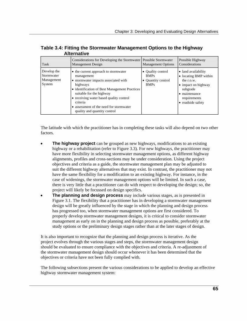
Chapter 3: Developing and Evaluating Design Alternatives
65
Table 3.4: Fitting the Stormwater Management Options to the Highway
Alternative Task
Considerations for Developing the Stormwater Management Design
Possible Stormwater Management Options
Possible Highway Considerations
Develop the Stormwater Management System
• the current approach to stormwater
management • stormwater impacts associated with
highways • identification of Best Management Practices
suitable for the highway • receiving water based quality control
criteria • assessment of the need for stormwater
quality and quantity control
• Quality control
BMPs • Quantity control
BMPs
• land availability • locating BMP within
the r.o.w. • impact on highway
subgrade • maintenance
requirements • roadside safety
The latitude with which the practitioner has in completing these tasks will also depend on two other factors. • The highway project can be grouped as new highways, modifications to an existing
highway or a rehabilitation (refer to Figure 3.3). For new highways, the practitioner may have more flexibility in selecting stormwater management options, as different highway alignments, profiles and cross-sections may be under consideration. Using the project objectives and criteria as a guide, the stormwater management plan may be adjusted to suit the different highway alternatives that may exist. In contrast, the practitioner may not have the same flexibility for a modification to an existing highway. For instance, in the case of widenings, the stormwater management options will be limited. In such a case, there is very little that a practitioner can do with respect to developing the design; so, the project will likely be focussed on design specifics.
• The planning and design process may include various stages, as is presented in Figure 3.1. The flexibility that a practitioner has in developing a stormwater management design will be greatly influenced by the stage in which the planning and design process has progressed too, when stormwater management options are first considered. To properly develop stormwater management designs, it is critical to consider stormwater management as early on in the planning and design process as possible, preferably at the study options or the preliminary design stages rather than at the later stages of design.
It is also important to recognize that the planning and design process is iterative. As the project evolves through the various stages and steps, the stormwater management design should be evaluated to ensure compliance with the objectives and criteria. A re-adjustment of the stormwater management design should occur whenever it has been determined that the objectives or criteria have not been fully complied with. The following subsections present the various considerations to be applied to develop an effective highway stormwater management system:
MTO Drainage Management Manual
66
• the current approach to stormwater management; • stormwater impacts associated with highways; • typical contaminants associated with highway stormwater; • identification of Best Management Practices suitable for highways; • receiving water based quality control criteria; • assessing the need for stormwater quality and quantity control; • location and layout of the stormwater management system.
The Current Approach to Stormwater Management The current approach to stormwater management applies a holistic approach to stormwater quantity and quality control. This approach is based on the selection, from a wide variety of control mechanisms, of the most suitable system that would best mitigate the impact of development both locally and on a watershed basis. This approach not only takes advantage of recent developments in quantity and quality control technology and practice, but also emphasizes the adoption of simple common sense principles in stormwater management. Some of these principles include source control, reduction of the development foot print, and conveyance control. New control practices apply quality control mechanisms, such as plant uptake and biodegradation, to stormwater treatment. This wide range of quantity and quality control measures are referred to as stormwater Best Management Practices (BMPs). The BMP approach is now the mainstream approach to the management of stormwater. However, many aspects affecting the performance of BMPs remain unknown, and are the subject of many research projects.
Stormwater Impacts Associated with Highways To select an appropriate stormwater management control measure, it is necessary to determine the type of impact this measure will mitigate. The modification of the flow patterns (e.g. runoff hydrograph distribution) and the deterioration stormwater quality, are two basic impacts associated with highways (refer to Table 2.2 in Chapter 2 for a detailed list of possible impacts). In general, the changes to stormwater quantity and quality due to highway development occurs as a result of the associated changes to the contributing watershed. These changes include reduction of imperviousness, flow concentration into channels and storm sewers, and regrading of the natural topography. These changes result in the following impacts.
Stormwater Quantity Impacts • Reduced infiltration and increased runoff volume.
Chapter 3: Developing and Evaluating Design Alternatives
67
• Reduction in the time of concentration resulting in increased peak flow rates. • Increased flow velocities. • Reduction of base flow in streams due to reduced infiltration, and flow diversion. • An increase in the frequency of erosive runoff events that result from typical, highly
frequent rain storms (e.g. summer thunderstorms).
Stormwater Quality Impacts • Sediment transport (i.e. sediment carried by water), as a result of erosion. • Contaminants are transported from the highway and external lands, to the receiving system. • Reduction in receiver assimilative capacity for contaminants as a result of a decrease in
baseflow. • Increased runoff water temperature due to an increase in paved area.
Typical Contaminants Associated with Highway Stormwater Typical contaminants associated with highway stormwater runoff include: • nutrients (phosphorus, and nitrogen) from fertilizer application; and • heavy metals (lead, cadmium, mercury, zinc, chromium, or arsenic) from engine and
brake wear. Other contaminants that may be associated with highway stormwater runoff are listed below for completeness: • organic and chemical oxygen demand from the decomposition and breakdown of organic or
chemical matter; and • oil and grease from vehicles. Contaminants in stormwater occur in two forms, particulate and dissolved. Particulate contaminants are either granular material, organic or chemical, or insoluble contaminant adsorbed into sediment particles. Particulate contaminants are, therefore, transported with the sediment. Soluble contaminants are in solution and are transported directly by the water. Tables 3.5 and 3.6 provide a description of the different mechanisms for water quantity and quality control. The methods for the control of contaminants in stormwater runoff depends on the type of contaminants and the path they take as they are transported within the natural environment. The extent of deterioration in stormwater quality as a result of development is not only a function of the increased amount of contaminants, but can also be due to changes to stormwater quantity. For example, the increase in sediment loading may be associated with increased erosion as a result of higher runoff flow velocities.
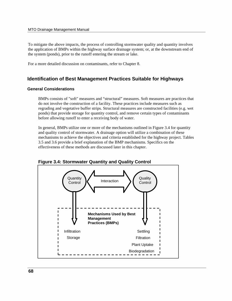
MTO Drainage Management Manual
68
To mitigate the above impacts, the process of controlling stormwater quality and quantity involves the application of BMPs within the highway surface drainage system; or, at the downstream end of the system (ponds), prior to the runoff entering the stream or lake.
For a more detailed discussion on contaminants, refer to Chapter 8.
Identification of Best Management Practices Suitable for Highways
General Considerations BMPs consists of "soft" measures and “structural” measures. Soft measures are practices that do not involve the construction of a facility. These practices include measures such as regrading and vegetative buffer strips. Structural measures are constructed facilities (e.g. wet ponds) that provide storage for quantity control, and remove certain types of contaminants before allowing runoff to enter a receiving body of water. In general, BMPs utilize one or more of the mechanisms outlined in Figure 3.4 for quantity and quality control of stormwater. A drainage option will utilize a combination of these mechanisms to achieve the objectives and criteria established for the highway project. Tables 3.5 and 3.6 provide a brief explanation of the BMP mechanisms. Specifics on the effectiveness of these methods are discussed later in this chapter. Figure 3.4: Stormwater Quantity and Quality Control
Quantity Control Interaction
Quality Control
Infiltration
Storage
Settling
Filtration
Plant Uptake
Biodegradation
Mechanisms Used by Best Management Practices (BMPs)

Chapter 3: Developing and Evaluating Design Alternatives
69
Table 3.5: Water Quantity Control Measures
Control Mechanism
What It Does
Benefit Infiltration
Storage
Reduces surface runoff by infiltrating portion of the runoff into the ground. Controls runoff flow rate by diverting a portion of the flow into storage for future release. (The total volume of flow remains unchanged except for the loss through evaporation from the storage basin surface area).
Quantity: • reduction of the total volume of surface runoff • reduction in the peak flow rate • maintaining of historic low flow in streams Quality: • control of stormwater temperature • maintaining stream assimilative capacity due to
an increase in low flow Quantity: • reduction in the peak flow rate • reduction of downstream drainage capacity
problem • control of flow velocity • reduction in the need for and/or extent of erosion
and sediment control measures Quality: • reduction in sediment transport due to erosion • reduction in the transport of contaminants
associated with sediment • reduction of sediment through settling
Table 3.6: Water Quality Control Mechanisms Control Mechanism
What It Does
Settling Filtration Plant uptake Biological uptake
Removal of particulate contaminants through settling of sediment. Removal of particulate contaminants through filtration by the soil or filtering material such as geotextile. Removal of soluble contaminants, particularly nutrients, through plant uptake. Reduction of biological oxygen demand by biodegradation.
The provision of vegetative canopy, and infiltration to increased base flow provide an effective mean of water temperature control. The Ministry of Environment and Energy (MOEE) has published a document titled Stormwater Management Practices Planning and Design Manual (MOEE, 1994), to provide general guidance on planning and design of BMPs. This document has been developed mainly to serve the land development industry. Highway drainage practitioners can refer to it for general guidance on planning matters, as well for BMP design details. This document divides the type of BMPs into three categories, lot level controls, conveyance control and end-of-pipe controls.
MTO Drainage Management Manual
70
BMPs Suitable for Highway Development
Three types of Best Management Practices can be used for highway application: There are three type of BMPs. They are as follows: • source control; • conveyance control; and • end-of-pipe control. It is recommended that the priority in applying these BMPs should follow the sequence presented, with end of pipe BMPs applied as the measures of last resort. Source Control These practices, for the most part, are soft measures. They include the following. • Reduction of chemical applications within the highway right-of-way.
These measures include the controlled use of right-of-way spraying of fertilizers, herbicides, and pesticides, and limiting the application of deicing chemicals, whenever possible. This measure is effective in controlling the production of these chemicals from within the right-of-way. However, their effectiveness is moderated by the transport of chemicals by the highway drainage system from sources outside of the right of way.
• Street sweeping/catchbasin cleaning. This BMP has been identified as an ineffective measure. (MOEE, 1994; U.S. Environmental Protection Agency, 1983(b); Versar Inc., 1989).
• Eliminating direct discharge from surface drainage system. Direct discharge of the highway runoff from the highway surface to a storm sewer or stream, results in the transport of contaminants directly to a receiver without any mitigation. A typical example of such occurrence is the discharge of bridge deck drainage directly into the stream below. This BMP measure involves directing the runoff from the surface drainage system to a grassed ditch or swale, and allowing it to flow for some distance before entering the receiving water.
Conveyance Control BMPs for conveyance control includes grassed ditches, vegetated buffer strips, and oil/grit separators. They are used to minimize the potential for scour, and to trap or filter contaminants before the flow enters the surface drainage system. • Grassed ditches and swales has shown to be an effective measure. It provides
improvement to runoff quality by filtering suspended sediment and heavy metals within the
Chapter 3: Developing and Evaluating Design Alternatives
71
surface drainage system. • Vegetated buffer strips consist of grass of forested vegetation designed to intercept
sheet flow and filter contaminants from the runoff prior to the flow entering the surface drainage system. In general, maintaining vegetation, whether natural or designed, has shown to be an effective, adaptive and flexible measure for highway applications.
• Oil/Grit separators is a preliminary treatment device long used in treating sanitary sewage and industrial wastewater where concentrations of oil and grit are high (Steel, E.W., 1960). Examples of appropriate applications are discharges from restaurant kitchens, abattoirs, meat processing plants and oil refinery storage yards. MOEE has noted a study which reported that the performance of oil/grit separators for ordinary urban runoff is poor (MOEE, 1994). As a result, this water quality control measure is not recommended as being suitable for highway application. Their use should be restricted to small areas such as petrol yards, car pool areas and parking lots.
End-of-Pipe Control End-of-pipe BMPs are sometimes referred to as structural BMPs. Table 3.5 provides a list of the different types of structural BMPs and the associated water quantity/quality control mechanisms. A brief description on the end-of-pipe BMPs that are most often considered for highway drainage management is provided below. The comments on each type serve as a general guide for practitioners to determine whether a given type of BMP may be applicable to their project. • Dry ponds are suitable for stormwater quantity management only. A dry pond detains
water during a storm event, and releases it at an outflow rate that is selected to ensure flow related impacts (e.g. flooding) are minimized.
• Wet ponds consist of a permanent pool of water which never drains (except during maintenance), and an additional storage space, on top of this pool, to hold the runoff that enters the pond in a storm event. The stored water is gradually released to a receiving water body. The permanent pool provides extended settling time equal to the interval time between storms, and allows the dilution of the discharge during a storm event by mixing the incoming flow with the existing pool of water (clean water). Wet ponds have been found to be very an effective and reliable end of pipe BMP in terms of contaminant removal.
• Extended dry detention ponds do not have a permanent pool like a wet pond does. An extended dry pond can only remove solid particles and not dissolved contaminants. The difference between an extended dry pond and a dry pond, is that the release rate of the extended dry pond is selected to mitigate water quality impacts, while the release rate of a dry pond is selected to minimize impacts related to flow (e.g. flooding).
• Constructed wetland have been reported to be an effective method of stormwater quality control; but, such reports are few and the sites of successful applications may be in more favourable climatic zones (e.g. the success reported by Martin E.H., 1988 is related to a project located in Florida). Technical literature dealing with the design of wetlands based on scientific principles, are also few and hard to find. Recent publications on wetland design are
MTO Drainage Management Manual
72
notably confined to natural wetlands (Marble, A.D., 1991; National Research Council,
1992; Washington State Department of Ecology, 1992). It is prudent not to use constructed wetlands in general practice in highway stormwater quality management until this technique can be evaluated further, and its effectiveness and reliability can be demonstrated beyond doubt. One aspect that may need to be studied if a wetland is built close to a highway is safety: if the wetland is successful and becomes a refuge for birds and small animals, will the movement of these animals create a safety hazard for them as well as for the highway users?
• Infiltration techniques include infiltration basins, infiltration trenches and porous pavement. These techniques have a high failure rate both in Ontario and U.S.A. (MOEE, 1994). For instance, they cannot be expected to function during the spring melt period because the subsurface soil will still be frozen at that time of the year. In addition, infiltration techniques have the following basic limitations:
• techniques are restricted to areas of well-drained soils; • infiltration systems commonly fail due to sediment clogging and reduced infiltration.
If the system is a subsurface infiltration system, this would require excavation and replacement of the granular material. If the system is a surface infiltration basin, this would require that the basin bottom be scraped/scarified, and the bottom soils replaced in some instances;
• potential groundwater contamination; and • the infiltrated water may weaken the subgrade of the highway pavement.
Some of the sediment clogging problems may be reduced through design changes. This may include use of sediment traps or head ponds to encourage sedimentation. These changes, however, remove mainly the large sediment particles and have little effect on the small particle sizes that cause clogging. Therefore, infiltration techniques are not recommended for use in highway projects until their effectiveness is substantiated, and, if used, it can be demonstrated that they will not undermine road subgrade and embankments.
Receiving Water Based Quality Control Criteria Stormwater quality design criteria in Ontario are based on the requirements for the protection of the receiving water quality. In 1991 the MOEE/MNR introduced the Interim Stormwater Quality Control Guidelines for New Development. Although these criteria were specifically created for new development, they have been used as a general guide to stormwater management in the province. These criteria provided water quantity control guidelines as a means for water quality control. The criteria required that runoff volumes of 13mm for a warm water fishery, and 25mm for a cold water fishery, be detained for 24 hours. The criteria also encouraged infiltration, source control, and highlighted that end-of-pipe facilities should be used as a means of last resort. However, these criteria were interim and they were expected to evolve as more end-of-pipe facilities came on line and performance monitoring became possible.
Chapter 3: Developing and Evaluating Design Alternatives
73
A new approach, introduced by MOEE in 1994, is based on the modelling of suspended solids removal efficiency as indicator to contaminant removal efficiency. This approach was based on the Fish Habitat Protection Guidelines for Developing Areas developed by MNR in 1993. These guidelines classify the receiver into three levels of fish habitat protection corresponding to a total suspended solids removal efficiency of 80%, 70%, and 60% respectively. A fourth level of protection was added to account for infilling situations. These criteria may be used as a guide for the design of water quality control facilities. However, the design criteria should be determined in the development of the project objectives and criteria, with the cooperation and involvement of environmental professionals, regulating agencies and the design engineer. Finally, the following fact is noted: that stormwater quality control is an evolving field and that no formal Provincial Policy is yet in place.
Assessing the Need for Stormwater Quality and Quantity Control The need for a suitable type of BMP originates from a need to mitigate the local impacts and watershed impacts that may result from highway development. The need should be identified with the aid of the project objectives and criteria, with input from the highway engineer, environmental professionals, regulating agencies, and others involved in water resources management. Existing watershed studies, when available, may provide guidance to the water quality requirements. It is important to note that structural BMP facilities may require substantial maintenance. Inadequate maintenance of a facility may lead to poor performance. In the worst case, the facility may become a nuisance instead of providing a benefit to the environment. In making a decision on whether or not to use a BMP facility, the potential long-term maintenance requirements should be considered.
Need For Stormwater Quality Control The need for stormwater quality control should be based on the sensitivity of the receiver to which the highway runoff will drain. The potential impacts associated with the highway project, together with the associated project objectives and criteria outlined in Chapter 2 of this manual, will flag the type of treatment required to protect the receiving watercourse. It is important to note that water quality control facilities may not be required under all conditions. A level of water quality control can be achieved through source control, modifications to the surface drainage system and from water quantity control facilities, as shown in Table 3.5.
MTO Drainage Management Manual
74
Need For Stormwater Quantity Control
The need for stormwater quantity control is determined by completing a hydrologic analysis of the existing pre-development scenario, and comparing the results to each proposed stormwater management plan that corresponds to each proposed highway development scenario. In most cases, the conveyance system (i.e. a ditch or sewer), will be developed as part of the surface drainage system. The specific form will depend on the configuration of the highway, surface topography, and other factors all of which are driven by the need to safely convey the highway runoff off the right of way to a suitable receiving watercourse.
Location and Layout Plan of the Stormwater Management System Issues to consider when selecting the location and configuration of BMP facilities are as follows. • Topography and availability of low lying areas suitable for locating BMP facilities. • Whenever possible, BMP facilities should be located outside of the flood plain (above
the 100-year elevation). Locations should be considered in consultation with the highway engineer, water resources engineers and environmental professionals.
• Availability of land to locate these facilities within the right-of-way and property acquisition issues, should be assessed.
• To confirm that any initial decisions remain to be applicable, this assessment will need to be revisited once the size of the facility has been determined.
• Consideration must also be given to maintenance access. Access should be sufficient to allow for the passage of equipment required for the dredging and removal of sediment from the settling facilities.
• Small storage facilities will have minimal flood control benefit which will diminish as the flood wave travels downstream.
• Multiple storage facilities located in the same drainage basin will affect the timing of the flood waves travelling downstream. This could increase or decrease flood peaks in downstream locations. Primary consideration should be given to the coordination of storage facilities with other drainage structures, on a regional or basin basis.
• It is possible to combine water quality and quantity facilities within a two cell facility, or have separate quality and quantity facilities. The cost of combined facilities is less, however, serious consideration needs to be given to the possibility of flow short circuiting and resuspension of sediment within the facility as high flows pass through.
• The use of separate quality and quantity facilities is recommended. In this case it is also recommended to provide flow splitting upstream of both facilities to minimize resuspension of sediment. A flow splitter redirects the flow in excess of that required for water quality control (i.e. 2-10 year flow), to the water quantity facility. This consideration should be viewed with full awareness that the planning for stormwater quality and quantity management is an integrated process, and should not be approached as two separate entities.
• The facility must fit into the natural setting and landscape design of the site.

75
Completing a Stormwater Quality Control Facility Design (i.e. Wet Pond, Extended Detention Pond)
The discussion in this section will focus on the design considerations for end-of-pipe stormwater quality control facilities. This will be covered under the following headings: • considerations at this stage of the quality control facility design; • applicable hydrologic methods for quality control facility design; and • applicable hydraulic methods for quality control facility design. Specific design details on the different components of wet ponds are discussed in Chapter 4. The discussion in this section provides the main considerations for design at the preliminary design stages. For further discussion and detail refer to the publication Stormwater Management Practices Planning and Design Manual (MOEE, 1994).
Considerations at this Stage of the Quality Control Facility Design When designing a BMP facility the following are the main design elements to be considered: • size; • length to width ratio; • detention time; • inlet and outlet configuration (location, type, capacity, and design of sediment forebay); • emergency bypass location, type and capacity; • maintenance access; • special safety and maintenance requirements; • grading and planting strategy; and • other design considerations.
Size The size of a wet pond refers to such parameters as: • surface area; • depth of 1-3 metres can be used as a guide for permanent pools; and • depth of active storage area.

MTO Drainage Management Manual
76
The size of a stormwater management facility is a function of the following factors. • Drainage area of the contributing basin. Wet ponds require a minimum
drainage area to sustain the permanent pool. As a general rule, a drainage area ≥5 hectares (MOEE, 1994) is sufficient to sustain the permanent pool.
• Precipitation. The precipitation data required for the design of wet ponds depends on the level of analysis required. There are two levels of analysis used for design of water quality control facilities: the Derived Probability Distribution (DPD) method and continuous simulation. These methods will be discussed in more detail further later on in this chapter. However, for the purpose of selecting the proper precipitation data (i.e. if the DPD design model is used), statistical factors based on long term precipitation records can be used. These factors include:
• the annual average rainfall; • the average event rainfall; • the average event duration; and • the average interval time between events.
Where continuous simulation is necessary, the entire precipitation record (i.e. for periods ≥10 years) will be required.
• The required sediment removal efficiency will be determined based on the sensitivity of the receiving body of water as discussed in the section on Receiver Based Water Quality Criteria. The sediment removal efficiency required can range from 60-80% depending on the classification of the receiver.
• The particle size distribution of the suspended sediment will depend on local sediment conditions and can be determined through sediment analysis or from existing studies, such as watershed studies, if available. The distribution is represented as the percentage by mass of the different particle sizes.
Length to Width Ratio • It is critical to provide the longest flow path in the pond to minimize short circuiting
and maximize the potential for trapping of sediment particles as they settle in the pond. This will improve the removal efficiency of the suspended sediment.
• A ratio > 3:1 can be used as a guide.
Detention Time • As a general guide, a detention time of 24 hours may be used to allow for sufficient time
for the settling of sediment. • The discharge flow rates should be checked to ensure no serious downstream impact, as

Chapter 3: Developing and Evaluating Design Alternatives
77
defined by the project objectives and criteria. • If the outlet is susceptible to clogging, the result will be a reduction in the detention
time. This may cause greater discharge flow rates, and greater outlet velocities.
Inlet and Outlet Configuration • If a large sediment load is expected, the provision of a sediment forebay may be of
benefit to trap large particles (particle size >100-150 µm) within a small area that is easier to maintain.
• The greatest benefit of the sediment forebay will be the even distribution of the flow as it moves across the inlet, to the active portion of the pond. This will minimize the potential for short circuiting.
• The design of the outflow control will determine the outlet flow rate and hence the detention time for the pond.
• The outlet may include devices such as weirs, orifice plates, perforated risers, or a combination of them.
Emergency Bypass Location, Type and Capacity • An emergency spillway should be designed to pass the Regulatory Flood, without
failure, under blocked outlet conditions. Reference should be made to the Technical Guidelines for Flood Plain Management in Ontario (MNR, 1987) for design criteria related to potential loss of life from dam failure.
Maintenance Access • Maintenance provisions should be included to ensure access to trash racks, and for
removal of sediment. • Access ramps should be designed to support maintenance equipment.
Special Safety and Maintenance Requirements • Trash racks and safety provisions to limit flow velocities should be provided on all inlet
structures. • Fencing may be necessary if there is the potential for public access. This should be
considered in a case-by-case situation as deemed necessary. • Roadside safety for errant vehicles should be provided. Consult the highway engineer
for further details.

MTO Drainage Management Manual
78
Grading and Planting Strategy
• If public access is possible, grading near the pond edge may be important to ensure
safety and to maximize the functionality of the pond. • When developing a grading and planting strategy, aesthetics should be considered. Consult a
landscape professional.
Other Design Considerations • A minimum freeboard depth of 0.3 m should be allowed between the maximum high
water level and the crest of the pond embankment. • A side slope of 4:1 or flatter should be allowed to provide for maintenance of the pond. • A geotechnical assessment may be needed to ensure structural stability of the embankments. • A minimum bottom grade of 1% should be provided to allow proper drainage.
Applicable Hydrologic Methods for Quality Control Facility Design The type of hydrologic analysis to be applied should depend on the level of risk associated with the downstream impacts. Event simulation may be used for preliminary design. For cases where an accurate prediction of downstream impact is required (i.e. for legal proceeding) continuous modelling may be necessary. For a discussion on the application of hydrologic computational procedures, refer to Appendix 3A. Specific aspects related to quality control facility design are provided below. For a detailed discussion on design applications, refer to Chapter 4. For background theory refer to Chapter 8.
Single Event Simulation When designing a stormwater quality drainage system, the single event approach is inadequate. This is because of the following three main reasons. • Stormwater quality management deals with frequent storm events for which removal of
contaminants is most effective and most economical. There is no generally accepted method to define such a frequent, single event.
• Stormwater runoff occurs intermittently, not continuously as sanitary sewage and industrial wastewater. A single event cannot account for the effects of this intermittent nature on stormwater quality impacts.
• The parameters of a storm that determine contaminant washoff by runoff, and subsequent removal by a BMP facility, are the volume, rate and duration of flow, and the time interval between storm events. The values of these parameters vary from storm to storm and moment to moment within a storm.
Chapter 3: Developing and Evaluating Design Alternatives
79
Therefore, when assessing stormwater quality management needs and design results, it is necessary to analyse a long series (e.g. 10 years or longer) of consecutive storm records (Huber, W.C. and R.E. Dickinson, 1988; Loganathan G.V. et al., 1994; Small, M.J. and DiToro, 1979; U.S. Environmental Protection Agency, 1986). One way to do this is through the use of statistical analysis, such as the Derived Probability Distribution (DPD) method, and another method is continuous simulation.
The DPD Method • The DPD method assumes that a historical series of storms and contaminants in the
runoff can be defined by a set of mathematical equations using statistical theories. By solving these equations, the statistics of the desired output can be obtained to be similar to continuous simulation.
• The DPD method is suitable for use in preliminary design, because of its ease of use and modest data requirements. It can be a powerful computation tool for comparing alternative types of BMP and alternative designs of a selected type of BMP.
• The model MTO SUDS (Adams, 1995), applies the DPD method. It is developed for MTO. Details on the application of this model are provided in Chapter 4.
Continuous Simulation • Continuous simulation is based on running a hydrologic computer model with the
precipitation and other climatic data gathered for the study area over a long period of time (e.g . 10 years or longer), at hourly intervals. The model routes the flows through the BMP facility under design, from the beginning to the end of the storm series. The results are then summarized into a set of statistics showing the expected performance of the facility with respect to the hydrologic conditions during the simulation period.
• This computational method involves a long and tedious process for data entry and calibration. However, the use of continuous simulation may be necessary and has been made more viable with the introduction of faster computer systems. Therefore, continuous simulation is more suitable for detail design.
• The model MTO SWMM extension is developed for MTO to perform this type of analysis. This extension is to be used in conjunction with the generic SWMM developed by USEPA. Details on the application of this model are provided in Chapter 4. Other models are also available that perform continuous modelling. Refer to Appendix 3B for a listing of the models that have been evaluated by MTO.
New models may be developed in the future and models may be available that have not been evaluated by MTO. It is the designer's responsibility to ensure that a suitable model is applied in the design.
MTO Drainage Management Manual
80
The theoretical background of computation methods and computer models is discussed in Appendices 3A, and in Chapter 8. Practitioners may use the information provided as a guide to select suitable computation methods for preliminary and detail design of BMP facilities. For details on the application of any computer models, refer to the model users manual.
Applicable Hydraulic Methods for Quality Control Facility Design Typically, in highway design applications, reservoir sizing is used to determine the size and configuration of a stormwater detention facility. Reservoir routing is utilized to determine the effect of a reservoir on hydrograph shape, timing and peak. For a discussion on computational procedures, refer to Appendix 3B. Specific aspects related to quality control facility design are provided below. For a detailed discussion on design applications, refer to Chapter 4. For background theory refer to Chapter 8.
Reservoir Sizing • Reservoir sizing involves three components:
• the physical configuration of the detention facility (volume and shape); • the hydraulics of the outlet structure; and • the sediment removal efficiency achieved based on the volume and shape.
• The physical configuration is quantified by determining the volume of storage for
various stages of depth or elevation. This relationship is commonly referred to as a stage versus storage representation.
• The hydraulics of the outlet structure is determined by applying basic culvert hydraulics and flow control principles (i.e. orifice controls and weir flow), to determine flow rates at the various stages of depth or elevation. This relationship is commonly referred to as a stage versus discharge representation.
• The sediment removal efficiency is determined by modelling the settleability of the different particle sizes. This can be achieved with the aid of a number of computer model or routines. Two models that provide analysis for sediment removal efficiency are the MTO SUDS and MTO SWMM. A description of these two types of models is provided in the previous section. For detailed information refer to the model users manuals.
Reservoir Routing The operation of any reservoir or stormwater detention facility, and its effect on the inflow hydrograph, is determined by inputting the reservoir configuration and hydraulic representation into a computer program.
Chapter 3: Developing and Evaluating Design Alternatives
81
• The computer program will route the inflow hydrograph through the facility and
determine the effects of the facility configuration and its hydraulic representation on the outlet hydrograph.
• In the design of stormwater management facilities, routing and sizing are completed simultaneously. The design process is, therefore, iterative.
• Multiple storage facilities located in the same drainage basin will affect the timing of the runoff throughout the conveyance system, which could increase or decrease flood peaks at downstream locations. Consideration should be given to coordinating storage facilities with other drainage structures on a regional or watershed basis.
For further discussion on the theoretical background of hydraulic computation methods and computer models, refer to Appendix 3B and Chapter 8. Practitioners may use the information provided as a guide to select suitable computation methods for preliminary and detail design of BMP facilities. For details on the application of any computer models, refer to the model users manual.

82
Completing a Stormwater Quantity Control Facility Design (i.e. Dry Ponds)
The discussion in this section will focus on the design considerations for end-of-pipe stormwater quantity control facilities. This will be covered under the following headings: • considerations at this stage of the quantity control facility design; • applicable hydrologic methods for quantity control facility design; and • applicable hydraulic methods for quantity control facility design. Specific design details on the different components of dry ponds are discussed in Chapter 4. The discussion in this section provides the main considerations for design at the preliminary design stages. For further discussion and detail refer to the publication Stormwater Management Practices Planning and Design Manual (MOEE, 1994).
Consideration at this Stage of the Quantity Control Facility Design When designing a BMP facility the following are the main design elements to be considered: • size; • detention time; • inlet and outlet configuration (location, type, capacity, and design of sediment forebay); • emergency bypass location, type and capacity; • maintenance access; • special safety and maintenance requirements; • grading and planting strategy; and • other design considerations.
Size The size of a dry pond refers to such parameters as: • surface area; and • depth. The size of a stormwater management facility is a function of the following factors.
Chapter 3: Developing and Evaluating Design Alternatives
83
• Drainage area. As a general rule dry ponds require a minimum drainage areas ≥ 5 hectares
(MOEE, 1994) to ensure sufficient flow to limit the potential for clogging of the outlet. • Precipitation data required for the design of dry ponds depends on the level of analysis
required. If event modelling will be used the precipitation can be provided based on:
• AES or district IDF curves; • an appropriate synthetic rainfall distribution (Kiefer and Chu, SCS, or other)
depending on the urban or rural nature of the contributing areas; and • any design should be checked using an event with a 24 hour duration.
The emergency spillway should be designed to convey the regulatory storm. In some cases continuous simulation may be needed. Refer to Appendix 3A for further guidance.
Detention Time • As a general guide, a detention time of 24 hours may be used. • The discharge flow rates should be checked to ensure no serious downstream impact, as
defined by the project objectives and criteria. • If the outlet is susceptible to clogging, the result will be a reduction in the detention
time. This may cause greater discharge flow rates, and greater outlet velocities.
Inlet and Outlet Configuration • If both stormwater quantity and quality control is necessary, it is recommended that
separate facilities be used. This is to avoid the sediment re-suspension concern associated with combined water quality/quantity control facilities. To achieve this flow splitting is recommended.
• Flow splitting can be provided upstream of the control facilities. This will ensure that the dry pond will function as a water quantity control facility only.
• The inflow rate to the dry pond will be a function of the threshold discharge rate of the flow splitter control device (weir, partial flume, or other).
• The design of the dry pond outlet structure will determine the outlet flow rate and hence the draw down time for the pond
• Outlet structures include devices such as weir, orifice plate, perforated riser, or a combination of these devices. A comprehensive discussion on the different types of outlet devices can be found in the Stormwater Management Practices Planning and Design Manual (MOEE, 1994).
MTO Drainage Management Manual
84
Emergency Bypass Location, Type and Capacity
• The emergency spillway should be designed to pass the Regulatory Flood without
failure, under blocked outlet conditions. Reference should be made to the Technical Guidelines for Flood Plain Management in Ontario (MNR, 1987) for design criteria related to potential loss of life from dam failures.
Maintenance Access • Maintenance provisions should be included to ensure access to trash racks and for
removal of any accumulated sediment. • Access ramps should be designed to support maintenance equipment.
Special Safety and Maintenance Requirements • Trash racks and safety provisions to limit flow velocities should be provided on all inlet
structures. • Fencing may be necessary if there is the potential for public access. This should be
considered on a case by case situation as deemed necessary. • Roadside safety for errant vehicles should be provided. Consult the highway engineer
for more details.
Grading and Planting Strategy • If public access is possible, grading near the pond edge may be important to ensure
safety and maximize the functionality of the pond. • When developing a grading and planting strategy, aesthetics should be considered. Consult a
landscape professional.
Other Design Considerations • A minimum freeboard depth of 0.3 metres should be allowed between maximum high
water level and the crest of the embankment. • A side slope of 4:1 or flatter should be allowed to provide for maintenance of the pond. • A geotechnical assessment should be provided to ensure structural stability of the
embankments. • A minimum bottom grade of 1% should be provided to allow proper drainage of the pond
following a storm.
Chapter 3: Developing and Evaluating Design Alternatives
85
Applicable Hydrologic Methods For Quantity Control Facility Design
The type of hydrologic analysis to be applied should depend on the level of risk associated with the downstream impacts. For preliminary design event simulation may be used. For cases where an accurate prediction of downstream impact is required (i.e. in legal proceedings), continuous modelling may be necessary. For a discussion on the application of hydrologic computational procedures, refer to Appendix 3A. Specific aspects related to quantity control facility design, are provided below. For a detailed discussion on design applications, refer to Chapter 4. For background theory refer to Chapter 8.
Single Event Modelling • If a drainage system is required to manage stormwater quantity only, the drainage
system can be designed based on a design storm or a series of design storms, for example, 2-100 year, and the Regulatory Flood.
• This approach is satisfactory because the objective of stormwater quantity management is to provide maximum conveyance capacity for the drainage system. Under event simulation, the use of a hydrologic simulation model will be necessary to calculate the inflow hydrograph(s).
• The Rational Method should not be used for storage facility design since the time distribution of the inflow (inflow hydrographs) is required to assess the effect of detention on the outflow time distribution (the outflow hydrograph).
• When using single event modelling 24-hour design storms should be used. • Refer to Appendix 3B for a complete listing of the different type of single event models
reviewed by MTO. Details on the application of one of these models, OTTHYMO, is provided in Chapter 4.
New models may be developed in the future and models may be available that have not been evaluated by MTO. It is the designer's responsibility to ensure that a suitable model is applied in the design. The theoretical background of computation methods and computer models is discussed in Appendix 3B, and in Chapter 8. Practitioners may use the information provided as a guide to select suitable computation methods for preliminary and detail design of BMP facilities. For details on the application of any computer models, refer to the model users manual.
Applicable Hydraulic Methods for Quantity Control Facility Design Typically, in highway design applications, reservoir sizing is used to determine the size and
configuration of a stormwater detention facility. Reservoir routing is utilized to determine the effect of a reservoir on hydrograph shape, timing and peak. For a discussion on computational

MTO Drainage Management Manual
86
procedures, refer to Appendix 3B. Specific aspects related to quantity control facility design, are provided below. For a detailed discussion on design applications, refer to Chapter 4. For background theory refer to Chapter 8.
Reservoir Sizing • Reservoir sizing involves two components:
• the physical configuration of the detention facility (volume and shape); and • the hydraulics of the outlet structure.
• The physical configuration is quantified by determining the volume of storage for
various stages of depth or elevation. This relationship is commonly referred to as a stage versus storage representation.
• The hydraulics of the outlet structure is determined by applying basic culvert hydraulics and flow control principles (i.e. orifice controls and weir flow), to determine flow rates at the various stages of depth or elevation. This relationship is commonly referred to as a stage versus discharge representation.
For further discussion on the theoretical background of hydraulic computation methods and computer models refer to Appendix 3B and Chapter 8. Practitioners may use the information provided as a guide to select suitable computation methods for preliminary and detail design of BMP facilities. For details on the application of any computer models, refer to the model users manual.
Reservoir Routing The operation of any reservoir or stormwater detention facility, and its effect on the inflow hydrograph, is determined by inputting the reservoir configuration and hydraulic representation into a computer program. • The computer program will route the inflow hydrograph through the facility and
determine the effects of the facility configuration and its hydraulic representation on the outlet hydrograph.
• In the design of stormwater management facilities, routing and sizing are completed simultaneously. The design process is, therefore, iterative.
• Multiple storage facilities located in the same drainage basin will affect the timing of the runoff throughout the conveyance system, which could increase or decrease flood peaks at downstream locations. Consideration should be given to coordinating storage facilities with other drainage structures on a regional or watershed basis.
87
References
Adams, B.J. (1995). Development of Analysis Methods for Stormwater Management with Ponds, Report to the Ontario Ministry of Transportation, University of Toronto, Department of Civil Engineering, Toronto. Carter K.B. (1985). "Nonpoint Source Pollution, Protecting Our Investment in Clean Water," J. Water Pollution Control Federation (WPCF), Vol. 57(2), Washington D.C. Dillon, M.M. (1990). Highway Runoff Water Quality: Literature Review, Ontario Ministry of Transportation, Toronto. Herricks E.E., D.J. Schaeffer and J.C. Kapsner (1985). "Complying with NPDES Permit Limits: When Is a Violation a Violation?" J. Water Pollution Control Federation (WPCF), Vol. 57(2), Washington, D.C. Huber, W.C. and R.E. Dickinson (1988). Stormwater Management Model, Version 4: User's Manual , Dept. of Environmental Engineering Sciences, University of Florida, Gainsville, FL. Leveck, G.E. and G. Quirion (1991). “City of Timmins 2nd Crossing of the Matagami River Class E.A. and Preliminary Design Study”. Proceedings of the Transportation Association of Canada Annual Conference, Vol. 2. Ottawa. Loganathan G.V. et al. (1994). "Sizing Storm-water Detention Basins for Pollution Removal," J. Environmental Engineering Division, Vol. 120(6), ASCE, NY. Marble, A.D. (1991). A Guide to Wetland Functional Design, ISBN 0-87371-672-X, Lewis Publishers. Martin E.H. (1988). "Effectiveness of an Urban Runoff Detention Pond-Wetland System," J. Environmental Engineering Division, Vol. 114(4), ASCE, NY. National Research Council (1992). Restoration of Aquatic Ecosystems, Science, Technology, and Public Policy, ISBN 0-309-04534-7, National Academy Press, Washington, D.C.
MTO Drainage Management Manual
88
Ontario Ministry of the Environment (1984). Water Management: Goals, Policies, Objectives and Implementation Procedures of the Ministry of the Environment, Toronto. Ontario Ministry of the Environment (May 1991). Interim Stormwater Quality Control Guidelines for New Development, Water Resources Branch and Central Region, Toronto, Ontario. Ontario Ministry of the Environment and Energy (1994). Stormwater Management Practices Planning and Design Manual, ISBN 0-7778-2957-6, Toronto, Ontario. Ontario Ministry of Natural Resources (1987). Flood Plain Management In Ontario, Technical Guidelines, ISBN 0-7729-1029-4, Toronto , Ontario. Ontario Ministry of Natural Resources (1994). Fish Habiat Protection Guidelines for Developing Areas, Toronto, Ontario. Ontario Ministry of Transportation and Communication (1980). MTO Drainage Manual, Downsview, Ontario. Ontario Ministry of Transportation (1989). MTO Drainage Management Technical Guidelines, Downsview, Ontario. Ontario Ministry of Transportation (1991). Ontario Highway Bridge Design Code, Downsview, Ontario. Ontario Ministry of Transportation (1991). Guidelines for the Preparation of Hydraulic Reports, Downsview, Ontario Paragon Engineering Ltd. Flood Damages, Volume 1, A Review of Estimation Techniques. Ontario Ministry of Natural Resources. Toronto. 1984. Paragon Engineering Ltd. Flood Damages, Volume 2, Guidelines for Estimation. Ontario Ministry of Natural Resources. Toronto. 1984. Sultan, M.B. “Working with a Politically Active Community”, Journal of the American Water Works Association, 85:11. Pg 54-57. 1993. U.S. Environmental Protection Agency (1982). Results of the Nationwide Urban Runoff Program, Appendices, Volumes 1 and 2, Water Planning Division, Washington, D.C. U.S. Environmental Protection Agency (1983(b)). Results of the Nationwide Urban Runoff Program, Volume 1 - Final Report, Water Planning Division, Washington, D.C.
Chapter 3: Developing and Evaluating Design Alternatives
89
U.S. Environmental Protection Agency (1986). Methodology for Analysis of Detention Basins for Control of Urban Runoff Quality, Report No. EPA440/5-87-001, Office of Water, Washington, D.C.. Washington State Department of Ecology (1992). Stormwater Management Manual for the Puget Sound Basin (the Technical Manual). Watt, W.E. (1994). Development of Hydrology Method for Medium-Sized Watersheds in Northern Onartio, Queen’s University, Department of Civil Engineering, Kingston, Ontario. Whiteley, H.R. and M.J. Douglas (1996). The Modified Index Flood Method Justification of Recommended Improvements, Guelph University, School of Engineering, Guelph, Ontario.

90
Appendix 3A: Hydrologic Computational Procedures
A summary of the hydrologic computational procedures used to determine flow rates are contained within. The procedures, programs and methodology are guidelines; it is the analyst's/designer's responsibility to recommend and justify the most appropriate methods. For a detailed discussion on the computational methods contained within, refer to Chapter 8. Hydrologic methodology or analysis, can be represented as follows. Figure 3A.1: Hydrologic Methodology
Regional Frequency Analysis
• Index Flood Method • Northern Hydrology
Method Rational Method
Single Station Frequency Analysis
NO
YES NO Do Flow Records Exist?
HydrographMethod
Required?
Flow Rates
YES
Select Modelling Approach (Based on
Precipitation Input)
Runoff- Hydrographs Channel Routing Storage Routing Water Quality • SWMM IV • QAULHYMO • MTO SUDS
Continuous Event Modelling
Runoff- Hydrographs Channel RoutingStorage Routing • LLUDAS • SWMM IV • OTTHYMO • QUALHYMO • OTTSEMM • HYMO • MIDUSS
Single Event
Modelling

Chapter 3: Developing and Evaluating Design Alternatives
91
Is Hydrograph Simulation Required?
Hydrograph simulation methods are mathematical representations of the response of a surface water system to specific physical processes such as infiltration, evaporation or detention, to produce a graph of runoff plotted against time. Hydrograph simulation methods are required under the following circumstances: • the drainage basin is expected to undergo significant urbanization; • the drainage area will be subject to stormwater management detention or channelization (i.e.
hydrograph routing is required); • the drainage area contains reservoirs and watercourses (i.e. hydrograph routing is required); • peak flow rates or volumes of runoff will be calculated from a historical rainfall or
precipitation event (e.g. Hurricane Hazel or Timmins storm); • different drainage options are to be tested including regulation (i.e. stormwater management
detention, diversion, etc.); • if land use, times of concentration, or soils conditions vary significantly across the
drainage basin; and • the Rational Method or Modified Index Methods are not applicable.
Hydrograph Simulation Is Required - Select The Modeling Approach Hydrographic simulation methods are simplified by applying appropriate computer programs or models. Hydrologic modeling is the computer simulation of the response of a catchment area to the input of precipitation, to produce a runoff hydrograph. There are two basic modeling approaches which are fundamentally based on the two forms of precipitation information that are available: • single event precipitation event; or • continuous precipitation records. Chapter 8 presents a more thorough discussion on precipitation inputs and design storms.
Single Event Modeling Single event modeling is the simulation of the precipitation/runoff process using a short duration precipitation event (i.e. durations ranging from 1hr to a few days). The precipitation event may be an actual recorded historical storm or a synthetic storm event that is based on a statistical analysis of recorded rainfall. Table 3A.1 compares the different single storm events.
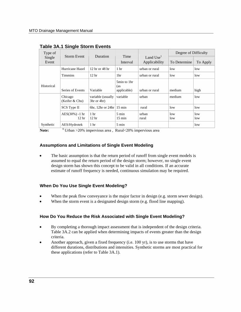
MTO Drainage Management Manual
92
Table 3A.1 Single Storm Events
Degree of Difficulty
Type of Single Event
Storm Event
Duration
Time Interval
Land Use P
1P
Applicability To Determine
To Apply
Hurricane Hazel
12 hr or 48 hr
1 hr
urban or rural
low
low
Timmins
12 hr
1hr
urban or rural
low
low
Historical
Series of Events
Variable
5min to 1hr (as applicable)
urban or rural
medium
high
Chicago (Keifer & Chu)
variable (usually 3hr or 4hr)
variable
urban
medium
low
SCS Type II
6hr, 12hr or 24hr
15 min
rural
low
low
AES(30%) -1 hr 12 hr
1 hr 12 hr
5 min 15 min
urban rural
low low
low low
Synthetic
AES/Hydrotek
1 hr
5 min
low
Note: P
1P Urban >20% impervious area , Rural<20% impervious area
Assumptions and Limitations of Single Event Modeling • The basic assumption is that the return period of runoff from single event models is
assumed to equal the return period of the design storm; however, no single event design storm has shown this concept to be valid in all conditions. If an accurate estimate of runoff frequency is needed, continuous simulation may be required.
When Do You Use Single Event Modeling? • When the peak flow conveyance is the major factor in design (e.g. storm sewer design). • When the storm event is a designated design storm (e.g. flood line mapping). How Do You Reduce the Risk Associated with Single Event Modeling? • By completing a thorough impact assessment that is independent of the design criteria.
Table 3A.2 can be applied when determining impacts of events greater than the design criteria.
• Another approach, given a fixed frequency (i.e. 100 yr), is to use storms that have different durations, distributions and intensities. Synthetic storms are most practical for these applications (refer to Table 3A.1).
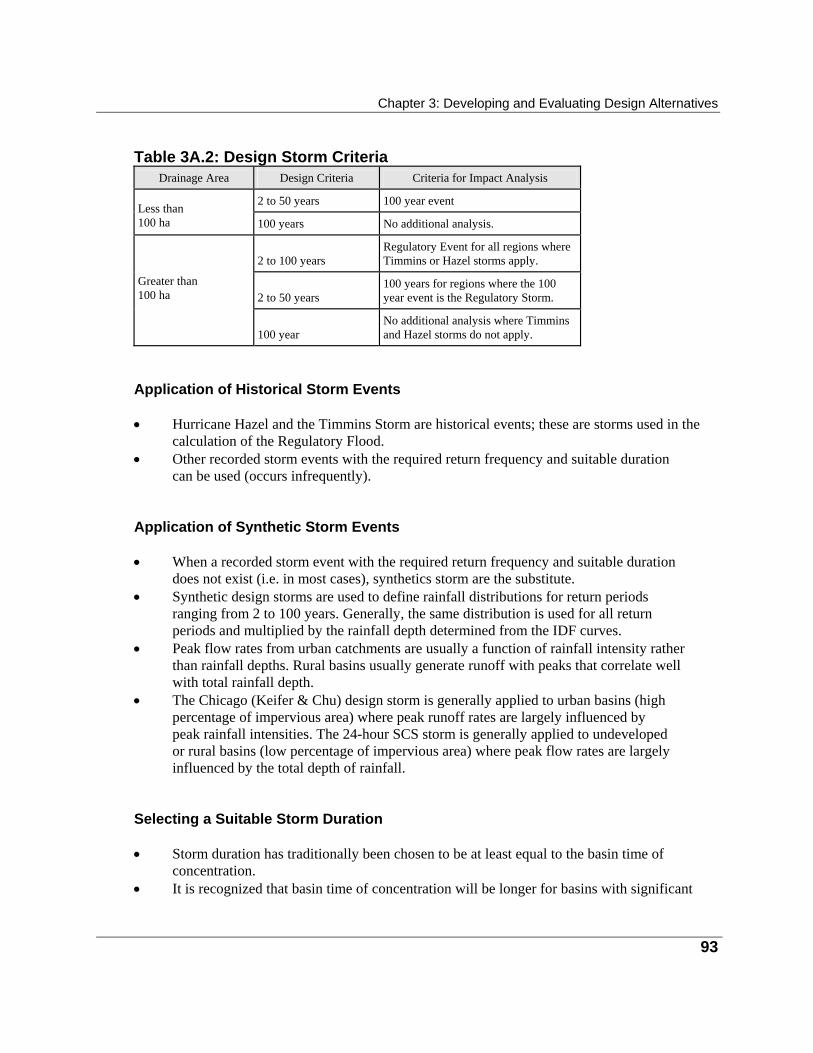
Chapter 3: Developing and Evaluating Design Alternatives
93
Table 3A.2: Design Storm Criteria
Drainage Area
Design Criteria
Criteria for Impact Analysis 2 to 50 years
100 year event
Less than 100 ha
100 years
No additional analysis.
2 to 100 years
Regulatory Event for all regions where Timmins or Hazel storms apply.
2 to 50 years
100 years for regions where the 100 year event is the Regulatory Storm.
Greater than 100 ha
100 year
No additional analysis where Timmins and Hazel storms do not apply.
Application of Historical Storm Events • Hurricane Hazel and the Timmins Storm are historical events; these are storms used in the
calculation of the Regulatory Flood. • Other recorded storm events with the required return frequency and suitable duration
can be used (occurs infrequently). Application of Synthetic Storm Events • When a recorded storm event with the required return frequency and suitable duration
does not exist (i.e. in most cases), synthetics storm are the substitute. • Synthetic design storms are used to define rainfall distributions for return periods
ranging from 2 to 100 years. Generally, the same distribution is used for all return periods and multiplied by the rainfall depth determined from the IDF curves.
• Peak flow rates from urban catchments are usually a function of rainfall intensity rather than rainfall depths. Rural basins usually generate runoff with peaks that correlate well with total rainfall depth.
• The Chicago (Keifer & Chu) design storm is generally applied to urban basins (high percentage of impervious area) where peak runoff rates are largely influenced by peak rainfall intensities. The 24-hour SCS storm is generally applied to undeveloped or rural basins (low percentage of impervious area) where peak flow rates are largely influenced by the total depth of rainfall.
Selecting a Suitable Storm Duration • Storm duration has traditionally been chosen to be at least equal to the basin time of
concentration. • It is recognized that basin time of concentration will be longer for basins with significant
MTO Drainage Management Manual
94
storage, and that it will vary for each basin and for each precipitation event. • A storm duration of 24 hours has been chosen arbitrarily for large drainage basins or
basins with stormwater management detention or other forms of storage (i.e. ponds, lakes, etc.). A 24-hour duration should be longer than most basin times of concentration for highway drainage applications.
• Where a drainage basin is serviced by a detention facility, a longer duration storm event should be used (i.e. 24hr).
Continuous Event Modeling Continuous event modeling is the simulation of the precipitation/runoff process using the entire long term meteorological record as input. A frequency analysis is performed on the annual simulated peak flow rates or volumes to determine a frequency curve. Continuous simulation is expected to generate runoff with a frequency which best approximates reality; however, calibration is required to achieve ultimate accuracy. Typical periods of rainfall data ranges from 10 to 40 years. Continuous simulation can be an expensive, complex and time consuming process, therefore, it is not used frequently for highway drainage design. An alternative to continuous simulation is the simulation of a series of individual historical storm events. Each event is simulated and a frequency analysis of the simulation results is then performed. Derived Probability Distribution - MTO SUDS In the design of stormwater quality control management facilities (BMP’s), it is necessary to analyse a long series (e.g. 10 years and longer) of consecutive storm records. One way to do this is through the use of the derived probability distribution (DPD) method. • The DPD method assumes that a historical series of storms and contaminants in the
runoff can be defined by a set of mathematical equations using statistical theories. By solving these equations, the statistics of the desired output similar to continuous simulation can be obtained.
• The DPD method is more suitable for use in preliminary design, because of its ease in use and modest data requirement. It can be a powerful computation tools for comparing alternative types of BMPs, and alternative designs of a selected type of BMP.
• There are a number of available computer models that are suitable for stormwater quality management. Table 3A.3 provides a summary of the models that have been evaluated by MTO, and have been found to be suitable for highway design applications in Ontario. In addition to these model, the DPD model MTO SUDS (Adams, 1995), which was developed for MTO, is also available. Details on the application of this model are provided in Chapter 4.
Chapter 3: Developing and Evaluating Design Alternatives
95
When Do You Use Continuous Event Modelling? • An accurate estimate of peak flow rate return periods (e.g. during legal proceedings) is
required. • To simulate low flow or base flow conditions. • For water quality analysis (i.e. pollutograph).
Hydrologic Computer Model Applications The application of hydrologic computer simulation models to highway drainage design should be undertaken with sound engineering judgement. As a general guide, the Professional Engineers of Ontario offer the following advice when undertaking the design of engineered structures using computer models: · determine the exact nature of assistance the program provides; · identify the theory on which the program is based; · determine the limitations, assumptions, etc. that are included in both the theory and the
program; · check the validity of the program for the intended applications; · make sure the program is correctly used; and · verify that the results are correct for each application. More specifically, the selection of a suitable hydrologic simulation program is dependent on whether the specific computer model suits the application. Factors to be considered when evaluating application include; • land use compatibility; • suitable infiltration methodology; • suitable hydrographic methods; • hydrologic routing capability; • Ontario suitability; • level of effort required; and • input data requirements. Some of these factors are discussed in more detail in Chapter 8. Chapter 8 also contains a summary of the appropriate computer models in Appendix 8A. For a quick reference on computer programs that have been previously evaluated by MTO, refer to Table 3A.3. For a complete evaluation, the practitioner should always refer to the user's guide\manual which accompanies each of the programs listed in Table 3A.3.
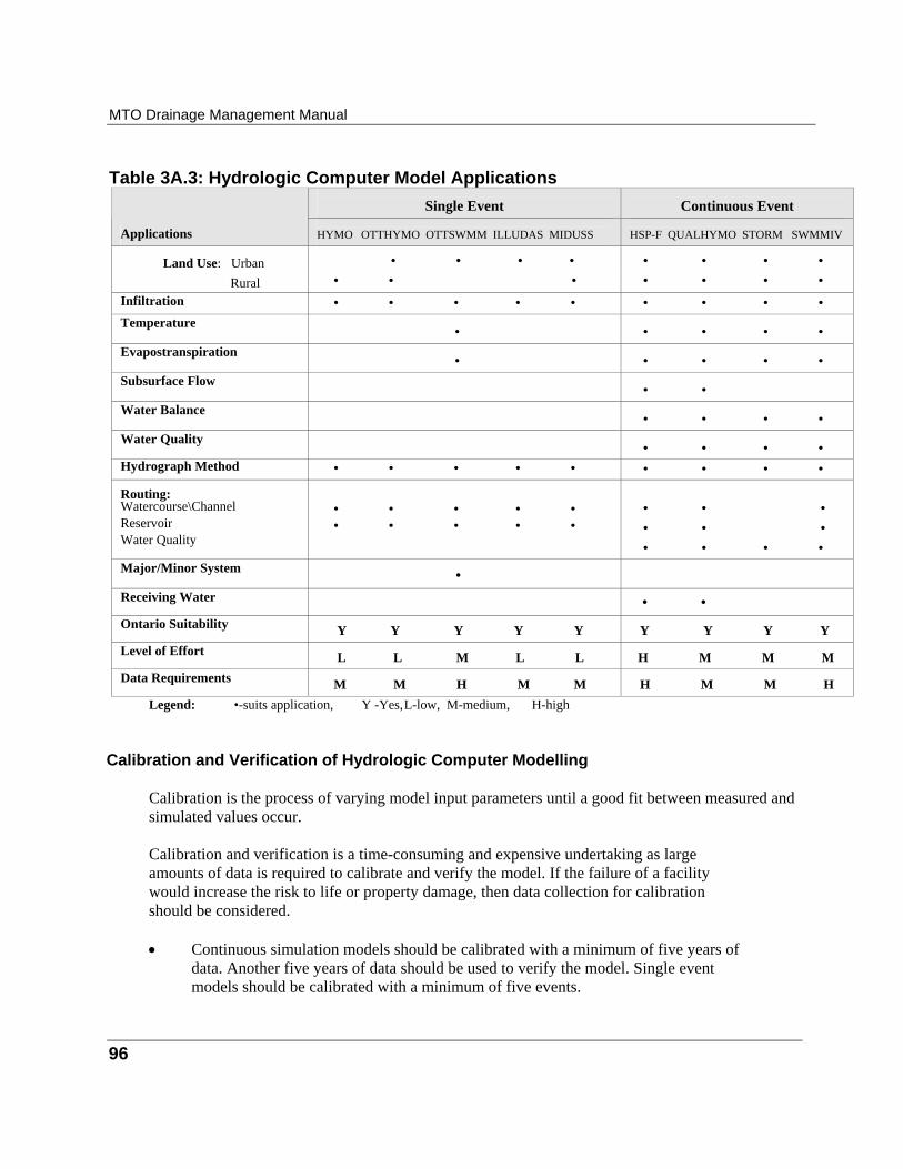
MTO Drainage Management Manual
96
Table 3A.3: Hydrologic Computer Model Applications
Single Event
Continuous Event
Applications HYMO OTTHYMO OTTSWMM ILLUDAS MIDUSS
HSP-F QUALHYMO STORM SWMMIV
Land Use: Urban Rural
• • • • • • •
• • • • • • • •
Infiltration • • • • • • • • • Temperature
• • • • • Evapostranspiration
• • • • • Subsurface Flow
• • Water Balance
• • • • Water Quality
• • • • Hydrograph Method • • • • • • • • •
Routing: Watercourse\Channel Reservoir Water Quality
• • • • • • • • • •
• • • • • • • • • •
Major/Minor System • Receiving Water • • Ontario Suitability Y Y Y Y Y Y Y Y Y Level of Effort L L M L L H M M M Data Requirements M M H M M H M M H
Legend: •-suits application, Y -Yes, L-low, M-medium, H-high
Calibration and Verification of Hydrologic Computer Modelling Calibration is the process of varying model input parameters until a good fit between measured and simulated values occur. Calibration and verification is a time-consuming and expensive undertaking as large amounts of data is required to calibrate and verify the model. If the failure of a facility would increase the risk to life or property damage, then data collection for calibration should be considered. • Continuous simulation models should be calibrated with a minimum of five years of
data. Another five years of data should be used to verify the model. Single event models should be calibrated with a minimum of five events.
Chapter 3: Developing and Evaluating Design Alternatives
97
• Hydrologic simulation models may be calibrated to the results of a single station flood
frequency analysis. • It is also good practice to perform a sensitivity analysis on the input parameters,
especially if calibration and verification cannot be undertaken. Sensitivity analyses are usually carried out on parameters which cannot be measured with significant accuracy.
Computer Application Errors Computer application errors are usually characterized by inaccurate outputs/results or by programs failing to terminate normally. The errors can generally be attributed to the following: • incorrectly entered data; • incorrect use of default values intrinsically provided by the program; • incorrect assumptions made in an application; • program misapplication; • poorly written user manuals; • incorrect interpretation of modelling results; and • programming errors. Incorrectly entered data probably accounts for many computer application errors. Incorrectly entered data reduces the designer's efficiency. The designer is encouraged to check data entries before program execution. Another common error is the use of computer programs for conditions beyond the author's intended range of application. Generally, there are conditions which cannot be modelled. It is the designer's responsibility to ensure computer programs are correctly applied.
Hydrograph Simulation Is Not Required and Flow Records Exist A single station frequency analysis of long-term stream flow records can determine peak flow rates required in the design of highway drainage works.
Single Station Frequency Analysis Single station frequency analysis is a statistical analysis of a series of recorded stream flow data, obtained from a single gauge station, to determine the specific frequency of occurrence for the sample of stream flow rates. Application of Single Station Frequency Analysis • Applicable if no significant upstream land use changes or flow control facilities (i.e. dams),
MTO Drainage Management Manual
98
are proposed, or have occurred, during the period of record (i.e. the basic assumption in the application of a frequency analysis is that the basin to which the results are applied is similar to the watershed from which the flood peaks were recorded).
• Generally, the longer the period of record the greater the confidence in the results (i.e. accuracy is proportionate to the years of record).
• Can be used to validate a hydrologic model. • A detailed discussion on frequency analysis is contained in Chapter 8. Reference to
documentation on the Consolidated Frequency Analysis 88 (CFA88- Environment Canada) and the HYDSTAT (Ontario Ministry of Natural Resources) computer programs can also be made when undertaking a single station frequency analysis.
Hydrograph Simulation is Not Required and Flow Records Do Not Exist Where flow records do not exist and a hydrograph method is not required, the following methods may be used to calculate peak flow rates: • Rational Method; or • Regional Frequency Analysis (Modified Index Flood or Northern Ontario Hydrology
Method).
Rational Method The Rational Method is a computational method that is used to estimate a design flow rate from a catchment area. The rational method calculates the peak flow rate at a particular point due to the runoff contributed from the catchment (drainage) area upstream.
Application of the Rational Method • The Rational Method is primarily used as a design tool for the design of minor
drainage systems such as storm sewers and ditches (refer to Chapter 4 for further details).
• The Rational Method can provide acceptable estimates of peak flow rates in small non-retentive rural watersheds. It is mostly applied in urban applications (i.e. small drainage area) as a design tool to size storm sewers.
• The Rational Method is not suitable for historic rainfall events (Hurricane Hazel or Timmins).
• Present practice in MTO limits its use to watershed drainage areas that are less than 100 ha. • The applicability of the rational method for rural watershed should be reviewed if
there is great variability in soil, vegetation or rainfall.
Chapter 3: Developing and Evaluating Design Alternatives
99
Regional Frequency Analysis
A regional frequency analysis utilizes regional watershed and climatic characteristics to calculate flow rates. It is most commonly used in watersheds that do not contain stream flow gauge recording stations. Details are discussed in Chapter 8. Applicable regional frequency analysis methods are: • the Modified Index Flood Method; and • the Northern Ontario Hydrology Method. Modified Index Flood Method The Modified Index Flood Method is a computational method that was developed from a regional frequency analysis of annually recorded maximum peak flow rates, to produce a statistical regression that calculates a 25 yr runoff event. All other peak flows are calculated by applying a frequency factor to the 25-year value. • Usually applied to basins where no stream gauge flow records exist. • The lower limit for the use of the Modified Index Flood method is 25 kmP
2P, as presented
in Chapter 8. • Results should be compared with results from at least one other method. • Refer to Chapter 8 for further details. The Northern Ontario Hydrology Method The Northern Ontario Hydrology Method is a computational method that was developed using a probabilistic/statistical approach, to determine peak flow rates for ungauged streams located in small and medium sized northern Ontario watersheds. • In small to medium watersheds, the storage in lakes, natural depressions and stream
valleys are potentially significant to attenuate the peak flows normally caused by the typical rain and snow melt in the spring.
• Northern Hydrology Method is more fully discussed in Development of Hydrology Method for Medium-sized Watersheds in Northern Ontario (Queens University, 1995). A summary of the method is also provided in Chapter 8.
100
Appendix 3B: Hydraulic Computational Procedures
A summary of the hydraulic computation procedures are contained within. The procedures, programs and methodology are guidelines; it is the analyst's/designer's responsibility to recommend and justify the most appropriate methods. For a detailed discussion on the computational methods contained within, refer to Part 2 and to Chapter 8 (Part 3). Generally, hydraulic computation includes procedures to conduct: • flow analysis (velocities, water surface profiles, subcritical/supercritical flow); • hydraulic computer model applications; • culvert hydraulics (inlet and outlet control); • reservoir sizing (stage-storage-discharge) and routing; • stream channel sizing and routing; and • stream channel stability analysis (tractive force, scour).
Flow Analysis Typically, in design applications, flow analysis is undertaken to determine the capacity of a particular drainage work. Additionally, flow analysis is used to determine other attributes of flowing water such as water level or surface profiles, velocities, total energy and momentum (force). A brief discussion on the various flow analysis methods is provided below. For a detailed discussion on background theory, equations and computational examples, refer to Chapter 8. For design applications, refer to Part 2. Manning Equation (Steady, Uniform Flow) • The Manning equation is a simple and quick method for sizing structures and calculating
velocities, or depth of flow. The Manning equation is applicable under steady uniform flow where there are no downstream hydraulic influences (i.e. no backwater effects), and the channel shape, lining material and slope are constant throughout the reach.
• Can be applied to open channels, culverts, bridges and storm sewer applications. • The MTO computer program CHANDE applies to open channel flow applications. Open Channel Flow - Standard Step Method (Steady, Gradually Varied Flow) • Utilizes the principles of continuity and conservation of energy to determine a water
surface profile. It is generally applied to open channel flow applications.
Chapter 3: Developing and Evaluating Design Alternatives
101
• Applies for steady, gradually varied flow conditions where downstream hydraulic
influences exist (i.e. backwater effects), and the stream shape, lining material and slope vary throughout the reach.
• An initial depth and flow rate must be known. The method is applicable for subcritical and supercritical flow conditions. Friction losses can be calculated using the Manning equation.
• The method is not applicable for rapidly varied flow conditions because losses due to acceleration cannot be calculated.
• HEC-2 (or HEC-RAS) is a computer program that is based on the standard step method and can be applied to open channel flow, bridge or culvert simulations.
Open Channel Flow - Unsteady Flow • For unsteady flow conditions, the principles of continuity and conservation of
momentum are used to determine water surface profiles and velocities. • Where predominantly unsteady state flow conditions exist, computer programs such as
DWOPPER should be applied. For a detailed list of hydraulic computer programs refer to Table 3B.1.
Open Channel Flow - Subcritical/Supercritical Flow • When calculating water surface profiles or analysing velocities, subcritical or
supercritical flow conditions must always be checked. • The Froude number, F Br B, (refer to Chapter 8) determines which condition is present:
• if F Br B > 1, supercritical flow exists (steep slopes); • if F Br, B < 1, subcritical flow exists (mild slopes); and • if F Br B = 1, flow is critical.
• For subcritical flow, water surface profiles are calculated from a known downstream point,
proceeding in a upstream direction. Flow velocities tend to be low. • Under supercritical flow conditions, water surface profiles are calculated from a know
upstream boundary condition (i.e. cross-section, velocity, slope), proceeding downstream. Flow velocities are high, increasing the potential for erosion.
• Hydraulic jumps will occur at the point where the flow condition changes from supercritical to subcritical. At this transition, turbulent flow occurs thereby increasing the potential for erosion. Whenever the supercritical condition governs, the hydraulic jump should be located. Refer to Chapter 8 for further details.
MTO Drainage Management Manual
102
Storm Sewer Applications - Hydraulic Grade line Analysis • A hydraulic grade line analysis can be used to determine water surface elevation or
pressure head within a storm sewer system. • Hydraulic grade line analysis applies for steady and unsteady flow conditions where
downstream hydraulic influences exist (i.e. backwater effects), which may affect the capacity of the storm sewer system.
• Also applied where there is a concern for storm sewer surcharging, can lead to highway flooding.
• Computations are facilitated through the use computer programs such as EXTRAN or the MTO Storm Sewer Model. See Table 3B.1.
Hydraulic Computer Model Applications The application of hydraulic computer simulation models to highway drainage design should be undertaken with sound engineering judgement. As a general guide, the Professional Engineers of Ontario offers guidance when undertaking the design of engineered structures using computer models; refer to the Appendix 3A, Hydrologic Model Applications. • The use of computer programs is recommended where the impact of failure is
significant. Although conditions may not warrant the use of computer programs, hydraulic analyses should still employ methods based on design flow conditions.
• Several computer programs have been written to determine water surface profiles for both steady and unsteady gradually varied flow conditions. The programs are written to analyse a given hydraulic condition rather than design according to a set of criteria. Computer programs based on rapidly varied flow conditions or the momentum principle are not readily available.
• Chapter 8 contains a summary of the appropriate computer models in Appendix 8A. For a quick reference on computer programs that have been previously evaluated by MTO, refer to Table 3B.1, which identifies the characteristics of several computer programs that can be used for hydraulic analysis
• The unsteady flow computer programs DWOPER and DAMBRK have been developed for large river systems and may not be applicable to many problems involving highway drainage. Also, EXTRAN has been developed for sewer systems. The designer is encouraged to review these programs and ensure the programs are used in the appropriate circumstances.
• The programs HEC-2 (or HEC-RAS) and WSPRO have been used extensively in the analyses and design of open channels. The programs can be used for both subcritical and supercritical flow conditions, but will not model rapidly varied flow. Applications where it is advantageous to apply HEC-2 (or HEC-RAS) or WSPRO instead of the "by-hand" methods (ie. Manning or Standard Step) are where:
Chapter 3: Developing and Evaluating Design Alternatives
103
• the reach is complex and requires many cross-sections to properly represent the reach; • different flow scenarios or stream configurations are to be simulated; or • a more detailed and accurate assessment is needed.
Computer Application Errors Computer application errors are usually characterized by inaccurate outputs/results or by programs failing to terminate normally. The errors can generally be attributed to the following: • incorrectly entered data; • incorrect use of default values intrinsically provided by the program; • incorrect assumptions made in an application; • program misapplication; • poorly written user manuals; • incorrect interpretation of modelling results; and • programming errors. Incorrectly entered data probably can account for many computer application errors. Incorrectly entered data reduces the designer's efficiency. The designer is encouraged to check data entries before program execution. Another common error is the use of computer programs for conditions beyond the author's intended range of application. Generally, there are conditions which cannot be modelled. It is the designer's responsibility to ensure computer programs are correctly applied.
Calibration and Verification of Hydraulic Computer Modelling Calibration is the process of varying model input parameters until a good fit between measured and simulated values occur. • The calibration and verification processes require large amounts of data including
surveyed cross-sections, recorded water levels and flow rates. The measurement of data necessary to calibrate and verify the model is a time-consuming and expensive undertaking. If the failure of a facility would increase the risk to life or property damage, then data collection for calibration should be considered.
• The calibration and verification procedure involves varying input parameters until a good agreement exists between measured and simulated values. The following parameters are typical of those varied during calibration:
• channel and flood plain surface roughness; and • flow expansion and contraction coefficients.
• The calibration and verification of all hydraulic models is strongly recommended.
MTO Drainage Management Manual
104
• If the results of calibration and verification are poor, then field conditions and input
data should be carefully reviewed before design simulations are carried out. • A sensitivity analysis of the input parameters should always be conducted. Hydraulic
parameters which are varied include roughness coefficients and expansion and contraction coefficients. A parameter which can influence water levels is the Manning roughness coefficient.
Selection of an Appropriate Computational Method • Most highway design applications simplify flow conditions by assuming steady
uniform or steady varied flow conditions. • Manning's equation should be used with caution as it may not be appropriate for all design
applications. It is convenient to use as a quick method for a rough, initial sizing. • Final design must always utilize the appropriate method based on the applicable flow
condition.
Culvert Hydraulics Typically, in design applications, culvert hydraulics is used to determine the capacity of culvert. Laboratory tests and field observations have shown that there are two major types of culvert flow: • flow with inlet control; and • flow with outlet control. A brief discussion on the culvert hydraulics is provided below. For a detailed discussion on background theory and equations refer to Chapter 8. For design applications, refer to Chapter 5.
Flow with Inlet Control • Inlet control means that the discharge capacity of a culvert is controlled at the
culvert entrance by the depth of headwater and the entrance geometry, including the barrel shape, cross-sectional area and the type of inlet edge.
• The roughness and length of the culvert barrel and the outlet conditions are not factors in determining the culvert capacity.
• The longitudinal slope reduces headwater only to a small degree, and can normally be neglected for conventional culverts flowing in inlet control.
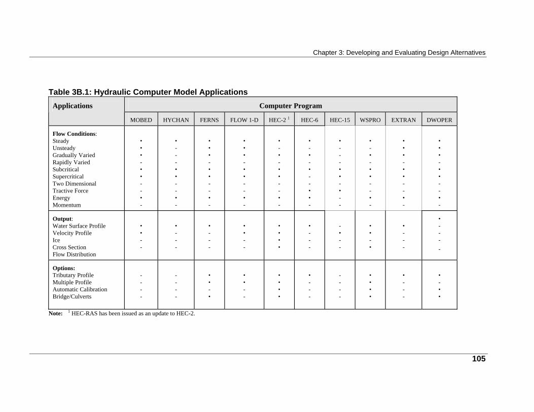
Chapter 3: Developing and Evaluating Design Alternatives
Table 3B.1: Hydraulic Computer Model Applications
Computer Program
Applications
MOBED
HYCHAN
FERNS
FLOW 1-D
HEC-2 1
HEC-6
HEC-15
WSPRO
EXTRAN
DWOPER
Flow Conditions: Steady Unsteady Gradually Varied Rapidly Varied Subcritical Supercritical Two Dimensional Tractive Force Energy Momentum
• • • - • • - - • -
• - - - • • - - • -
• • • - • • - - • -
• • • - • • - - • -
• - • - • • - - • -
• - • - • - - • • -
• - - - • • - • - -
• - • - • • - - • -
• • • - • • - - • -
• • • - • • - - • -
Output: Water Surface Profile Velocity Profile Ice Cross Section Flow Distribution
• • - -
• - - -
• - - -
• • - -
• • • •
• - - -
- • - -
• • - •
• - - -
• - - - -
Options: Tributary Profile Multiple Profile Automatic Calibration Bridge/Culverts
- - - -
- - - -
• • - •
• • - -
• • • •
• - - -
- - - -
• • • •
• - - -
• - • •
Note: 1 HEC-RAS has been issued as an update to HEC-2.
105
MTO Drainage Management Manual
106
Flow With Outlet Control
• Outlet control means that the discharge capacity of a culvert is controlled by the depth of
tailwater including the velocity head within the barrel, entrance losses and friction losses. • The roughness, length of the culvert barrel, and slope are factors in determining the culvert
capacity.
Analysis Approach • In most cases the operating flow condition of the culvert, is not known. • This unknown is avoided by computing the headwater depth (refer to Chapter 5 for
details) for both the inlet and outlet controls; the higher value then indicates the type of control, and should be used as the governing depth in design.
• This method is relatively accurate except for the few cases where the headwater is approximately the same for both types of control.
• Computational procedures are simplified with the use of design aids (i.e. nomographs-refer to the Design Charts) and computer programs (see Table 3B.1).
Reservoir Sizing and Routing Typically, in highway design applications, reservoir sizing is used to determine the size and configuration of a stormwater detention facility. Reservoir routing is utilized to determine the effect of a reservoir on hydrograph shape, timing and peak flow. A brief discussion is provided below. For a detailed discussion on background theory refer to Chapter 8. For design applications, refer to Chapter 4.
Reservoir Sizing • Reservoir sizing is comprised of two components:
• the physical configuration of the detention facility (volume and shape); and • the hydraulics of the outlet structure.
• The physical configuration is quantified by determining volume of storage for various
stages of depth or elevation. This relationship is commonly referred to as a stage vs storage representation.
• The hydraulics of the outlet structure is determined by applying basic culvert hydraulics and flow control principles (i.e. orifice controls and weir flow), to determine flow rates at the various stages of depth or elevation. This relationship is commonly referred to as a stage vs discharge representation.

Chapter 3: Developing and Evaluating Design Alternatives
107
Reservoir Routing
• The operation of any reservoir or stormwater detention facility, and its effect on the
inflow hydrograph, is determined by inputting the reservoir configuration and hydraulic representation into a computer program.
• The computer program will route the inflow hydrograph through the facility and intrinsically determine the effects that the configuration and hydraulic representation will have on the hydrograph.
• In the design of stormwater management facilities, routing and sizing are simultaneously completed and the overall design process becomes iterative.
• Reservoir routing is also used in hydrologic modelling.
Stream Channel Sizing and Routing In highway design applications, stream channel sizing is used to determine the size and configuration of proposed modifications to an existing watercourse. Stream channel routing is utilized to determine effects on hydrograph shape, timing and peak flows. A brief discussion is provided below. For a detailed discussion on background theory refer to Chapter 8. For design applications, refer to Chapter 5.
Stream Channel Sizing • The physical configuration of a stream channel is quantified by determining volume
of storage for various stages of depth or elevation. This relationship is commonly referred to as a stage vs storage representation.
Stream Channel Routing
• The operation of any reservoir, and its effect on the inflow hydrograph, is determining
by inputting the physical configuration into to a computer program (see Table 3B.1). • The computer program will route the inflow hydrograph through the stream
channel and intrinsically determine the effects that the configuration and hydraulic representation will have on the hydrograph.
• In the design of stream channel systems, routing and sizing are simultaneously completed and the overall design process becomes iterative.
• Stream channel routing is also used in hydrologic modelling.
Stream Channel Stability Analysis Channel stability analysis is critical in any stream channel, bridge or culvert design application and is used to determine suitable protection against erosion. For design applications, refer to Chapter 5.
MTO Drainage Management Manual
108
• Tractive force analysis is used in the design and analysis of stream channel lining
material. Determines shear force that is exerted by the mass of flowing water on the stream channel. Lining material can then be checked to ensure resistance against the shear or tractive force of the moving water.
• The permissible velocity method is used in the design and analysis of stream channel lining material. Given velocity in a stream channel, lining material can be checked to ensure resistance against the velocity of the moving water.
• Scour analysis is typically applied to piers and bridge abutments and at culvert outlet locations.

109
Appendix 3C: Evaluation
Drainage is usually only one of many concerns in highway projects. This appendix focuses on evaluation requirements for drainage work alone. Evaluations that encompass a broader range of impacts is beyond the scope of this appendix. Evaluation is undertaken before decisions are made in order to help in the decision making. It is not a substitute for the decision making process. This appendix focuses on the evaluation task and not on decision making. Moreover, it does not consider budgeting, capital finance, cost control and cost recovery since these are not normally part of evaluation.
What Is Evaluation? Evaluation is a deliberate, explicit process to help identify the best option when several are being considered. The best option is one that: • achieves the same results as other options but at a lower cost; or • costs the same but has fewer adverse effects; or • costs more but has additional benefits that justify the extra cost. Do an evaluation when there is a decision to make, for example, consider the following. • Which option should be pursued? • Is this a “go” or a “no go” situation? Evaluation serves no purpose if there is no choice to be made.
Why Do Evaluations? When a decision is made without an evaluation, the chances of making a poor decision increase. What’s a poor decision? One that fails to take all of the costs and benefits into account. For example a poor decision may: • not be clear about the objectives; or • ignore future operating and maintenance costs; or • overlook significant impacts (flooding, fisheries, erosion,...); or • fail to weigh the concerns of people who are affected by the project.
MTO Drainage Management Manual
110
Input from Earlier Tasks
The evaluation process uses the following types of information from the tasks that precede it: • descriptions of the impacted social and natural environments; • descriptions of objectives and criteria; and • descriptions of highway alternatives and drainage options proposed and the effects of each
alternative/option (e.g. achievement of objectives, costs).
What is Included in an Evaluation Process? There are three basic steps in evaluation: 1) describe the options; 2) determine the costs and benefits for each
option; and 3) compare options based on costs and
benefits. Describing the options is completed prior to the evaluation. Descriptions should include: • capital, operating and maintenance costs; and • measures indicating the achievement of study objectives (including the avoidance of
adverse impacts). A variety of techniques are used to determine costs and benefits, and to compare options based on those costs and benefits. Impact matrices are one of the most common techniques. Other tools include cost-benefit and cost-effectiveness analysis, and non-monetary rating and ranking methods. Valuation methodologies are discussed in the next section. A good evaluation process is as follows. Inclusive: all stakeholder are identified and included in the process. Complete: all beneficial and adverse effects are taken into account. Transparent: impacts are described and evaluated in a way that is readily understood. Objective: the evaluation process creates information that is accurate and balanced. Logical: objectives and criteria are clearly defined and linked to the evaluation
of project effectiveness and project impacts. Iterative: the evaluation proceeds in stages. First, options that are infeasible,
ineffective or inferior are dropped. The remaining options are screened to select a preferred option.
What are costs and benefits? Other words for “costs and benefits” are “pros and cons” or “advantages and disadvantages” or “beneficial and adverse impacts.” These are not just the monetary costs and benefits. Non-monetary costs and benefits that are measured in quantitative or qualitative ways are included.

Chapter 3: Developing and Evaluating Design Alternatives
111
Keep the Evaluation Simple
For most studies, a basic evaluation will be all that is called for. The minimum requirements of a basic evaluation are: • estimate life cycle costs for all feasible options; • estimate the effectiveness of every option in satisfying every objective; • summarize costs and benefits for all the options in an impact matrix; • consult all major stakeholder and account for their concerns; • compare options on the basis of their ability to satisfy study objectives; and • identify the best option and a provide rationale for its selection. Plan the analysis carefully to meet the minimum requirements. For instance, if you require estimates of expected annual flood damages, then you must complete the necessary background field investigations and hydrologic modeling analyses. If, as is usually the case, some criteria are not assigned dollar values, then a method is needed to compare monetary and non-monetary criteria data. A more sophisticated approach to evaluation may be required under the following conditions: • the study area is a complex watershed with multiple competing objectives; • water management issues have a high public profile and are surrounded with controversy; • there are prominent stakeholder groups with conflicting interests; and • regulatory requirements demand methodological sophistication. If this is the case then services of an expert in evaluation may be required. The evaluation must be objective and fair and it must appear to be so.
Give All Stakeholder an Opportunity to Be Heard Public participation methods that do not invite dialogue violate this requirement, as do evaluation methods that rely strictly on experts rather than the people who are affected by proposed alternatives.
Do Not Bias the Evaluation by Your Choice of Methods A commitment to benefit cost analysis, for example, narrows the analysis to those effects that can be valued monetarily and excludes effects that are “intangible”. On the other hand, a decision not to do any costing would leave economic objectives in limbo.
MTO Drainage Management Manual
112
The Evaluation Team In smaller studies, evaluation can be completed by the technical analyst(s) under the direct supervision of senior staff. In larger studies, an evaluation team may be used to oversee the work. The primary function of the evaluation team is to oversee the technical work and guide the presentation of results. Ideally, an evaluation team includes: • persons who will help formulate final recommendations; • persons with technical expertise in drainage and evaluation; • persons who do the technical work; and • persons who are involved with the project from the outset. Analysts who are responsible for the evaluation will require strong quantitative skills, will have a good understanding of drainage work and should have training in basic evaluation techniques (e.g. engineering economics, environmental planning or applied economics).
Public Consultation Public consultation gives people and organizations who are outside of the planning and design process an opportunity to participate in the process. Public participants may include local politicians, land owners, residents and businesses in the study area, special interest groups and external agencies. The role of the public in a consultation program can range from passive providers of information to active participants in the planning process. But whatever their role, the public consultation program should not be a “smoke and mirrors” exercise or a “rubber stamp”, for decisions that are already made. Nor should it be used to manipulate public opinion or mounted simply to satisfy E.A. process requirements (i.e. “going through the motions”). Programs that have these motivations risk alienating the public and producing counter productive results such as delays or failures to secure project approvals. Many potential benefits can follow from effective public consultation. Early consultations can be used to identify public issues and refine the study objectives. Public inputs can also lead to modifications in other aspects of the planning process, for instance, the study area was enlarged after public consultations on a river crossing design project in Timmins (Leveck and Quirion, 1991). Interactions with the public can also help the study team to identify new study options and refine design concepts. This often happens in the process of resolving conflicts with the public that arise from opposition to proposed options. The end result of successful public consultation efforts
• information dissemination; • interviews with key informants; • surveys or focus groups; • informal meetings to exchange information and resolve conflicts; • periodic open house meetings; • public advisory committee participation; and • public representation at hearings (e.g. E.A. Board, O.M.B., drainage tribunal).
Possible components of a public participation program:
Chapter 3: Developing and Evaluating Design Alternatives
113
is speedier public acceptance of projects (Sultan, 1993).
Evaluation Methods Basic methods that are commonly applied in evaluations are described in subsequent sections. More elaborate evaluation methods, such as optimization models that may be used in complex studies, are not discussed. Moreover, this appendix does not deal with a range of socio-economic tools that are used to describe economic and community impacts. Some of the methods of an economic or financial nature are also applied in budgeting, financial planning, cost control and cost recovery, but these topics are not covered here.
Approaches To Valuing Impacts Value measures the significance that people attach to things. Values are used to understand and compare the relative merits of options and to help decision makers identify preferred options. In evaluation studies, the value associated with an effect depends both on its magnitude and on the importance assigned to that effect by the stakeholder.
Monetary Measures Prices measure value for goods and services that are bought and sold in markets. Many of the effects of drainage projects can be valued directly using market prices (e.g. capital costs, flood damages, land values), while others can be valued indirectly with market prices (e.g. travel time, recreation).
Non-Monetary Measures Many criteria are not easily valued using market prices (e.g. aesthetic impacts, health, safety, ecosystem impacts). Methods are available to assign either monetary or non-monetary values to these. Simple non-monetary methods involving low/medium/high ratings are recommended. If you use a rating scheme like this for a criteria, first define what is meant by the terms low, medium and high with respect to that criteria; for example the terms may be assigned on the basis of the estimated magnitude of the impact or its duration. In developing a rating scale, it is advisable to have a rating value below the “low” rating corresponding to a zero or negligible effect level.
MTO Drainage Management Manual
114
Capital Costs
Capital costs are the investment costs incurred at the outset of a project to acquire land, and construct or install long lived physical assets such as earth embankments, bridges, fish habitat structures and armoured channels. Capital costs will include costs for land acquisition, planning and design, construction, and commissioning.
Capital costs measured as the initial cash requirement to pay for the investment. Financial costs, which include depreciation and amortization costs, are not considered in an evaluation exercise. To include both the investment cost and the annual depreciation and interest costs in the analysis, would amount to double counting.
Capital grants affect the manner in which capital costs are distributed among different funding agencies, but they do not affect the overall cost of a project to society. Since public sector projects should be screened on the basis of total social cost, any grants that may be available to offset capital costs should be ignored in an evaluation. When assessing study options and preliminary design options capital costs are approximated from design data. Project costing at these stages will not be accurate enough to provide the basis for budgeting and tendering of contracts, but it will provide a reliable means of selecting the preferred option.
Estimating Capital Costs - Unit Costing Unit costing, the principal method used in estimating capital costs, is done as follows: 1) measure physical quantities of standard project components as rough take offs from project
design data; 2) cost project components individually as follows: (unit cost) x (no. of units); 3) estimate total project costs as the sum of individual component costs; and 4) add an allowance for engineering and contingencies. Costing forms are used to summarize the analysis (see Example 3C.1). In addition to providing a summary of the costing calculations, always identify the reference year for the unit cost data in the table. Unit costing will only provide an estimate of the construction cost portion of capital costs. Other costs are incurred for elements such as engineering and legal services, land acquisition, the relocation of utilities, taxes and unforeseen contingencies. Land costs are the subject of a separate
Double counting occurs when an impact is given too much weight in an evaluation because its value is counted twice.
Capital Cost Analysis: • include investment costs, engineering costs land costs and other direct project costs; and • do not include financing costs, amortization, depreciation, or grants.
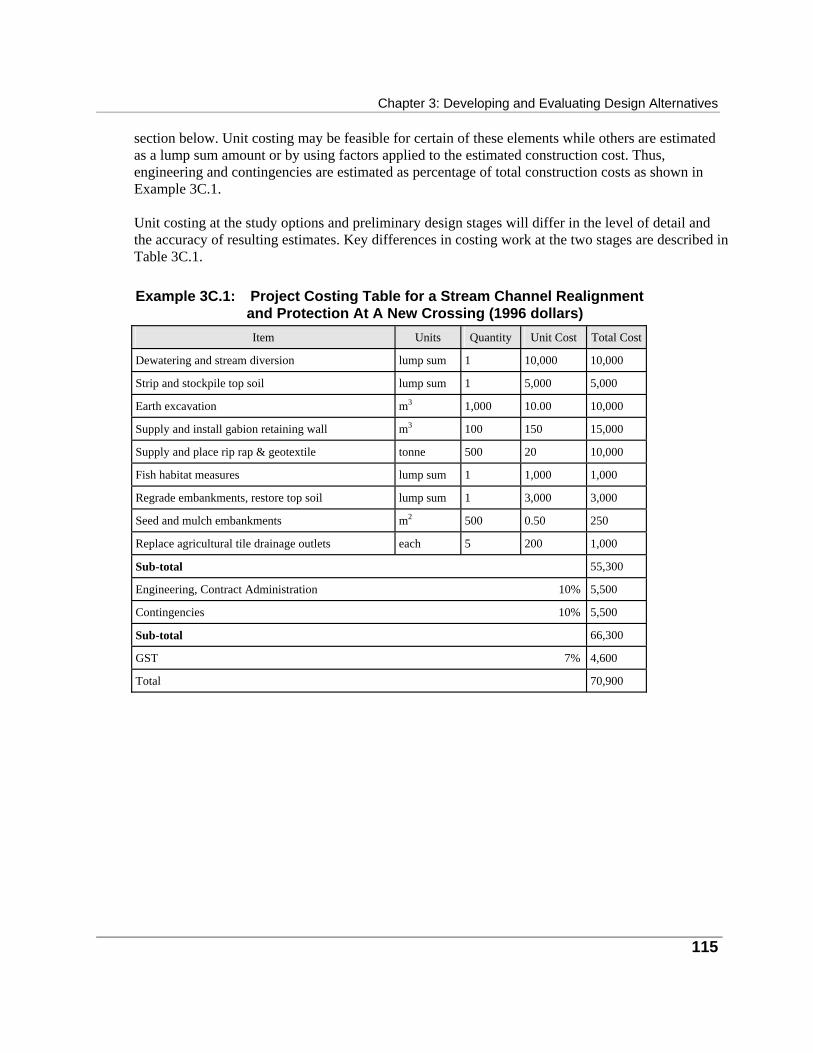
Chapter 3: Developing and Evaluating Design Alternatives
115
section below. Unit costing may be feasible for certain of these elements while others are estimated as a lump sum amount or by using factors applied to the estimated construction cost. Thus, engineering and contingencies are estimated as percentage of total construction costs as shown in Example 3C.1. Unit costing at the study options and preliminary design stages will differ in the level of detail and the accuracy of resulting estimates. Key differences in costing work at the two stages are described in Table 3C.1. Example 3C.1: Project Costing Table for a Stream Channel Realignment
and Protection At A New Crossing (1996 dollars)
Item
Units Quantity
Unit Cost
Total Cost
Dewatering and stream diversion
lump sum
1
10,000
10,000
Strip and stockpile top soil
lump sum
1
5,000
5,000
Earth excavation
m3
1,000
10.00
10,000
Supply and install gabion retaining wall
m3
100
150
15,000
Supply and place rip rap & geotextile
tonne
500
20
10,000
Fish habitat measures
lump sum
1
1,000
1,000
Regrade embankments, restore top soil
lump sum
1
3,000
3,000
Seed and mulch embankments
m2
500
0.50
250
Replace agricultural tile drainage outlets
each
5
200
1,000
Sub-total
55,300
Engineering, Contract Administration 10%
5,500
Contingencies 10%
5,500
Sub-total
66,300
GST 7%
4,600
Total
70,900
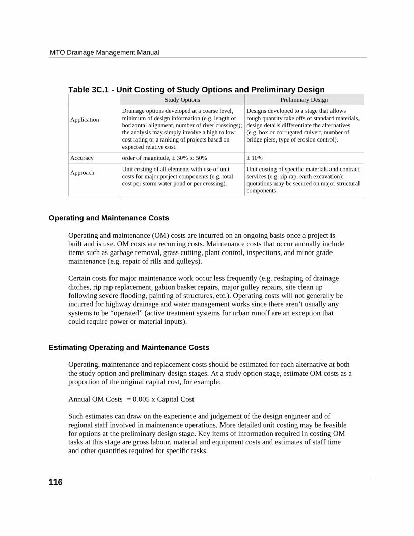
MTO Drainage Management Manual
116
Table 3C.1 - Unit Costing of Study Options and Preliminary Design
Study Options
Preliminary Design
Application
Drainage options developed at a coarse level, minimum of design information (e.g. length of horizontal alignment, number of river crossings); the analysis may simply involve a high to low cost rating or a ranking of projects based on expected relative cost.
Designs developed to a stage that allows rough quantity take offs of standard materials, design details differentiate the alternatives (e.g. box or corrugated culvert, number of bridge piers, type of erosion control).
Accuracy
order of magnitude, ± 30% to 50%
± 10%
Approach
Unit costing of all elements with use of unit costs for major project components (e.g. total cost per storm water pond or per crossing).
Unit costing of specific materials and contract services (e.g. rip rap, earth excavation); quotations may be secured on major structural components.
Operating and Maintenance Costs
Operating and maintenance (OM) costs are incurred on an ongoing basis once a project is built and is use. OM costs are recurring costs. Maintenance costs that occur annually include items such as garbage removal, grass cutting, plant control, inspections, and minor grade maintenance (e.g. repair of rills and gulleys). Certain costs for major maintenance work occur less frequently (e.g. reshaping of drainage ditches, rip rap replacement, gabion basket repairs, major gulley repairs, site clean up following severe flooding, painting of structures, etc.). Operating costs will not generally be incurred for highway drainage and water management works since there aren’t usually any systems to be “operated” (active treatment systems for urban runoff are an exception that could require power or material inputs).
Estimating Operating and Maintenance Costs Operating, maintenance and replacement costs should be estimated for each alternative at both the study option and preliminary design stages. At a study option stage, estimate OM costs as a proportion of the original capital cost, for example: Annual OM Costs = 0.005 x Capital Cost Such estimates can draw on the experience and judgement of the design engineer and of regional staff involved in maintenance operations. More detailed unit costing may be feasible for options at the preliminary design stage. Key items of information required in costing OM tasks at this stage are gross labour, material and equipment costs and estimates of staff time and other quantities required for specific tasks.

Chapter 3: Developing and Evaluating Design Alternatives
117
Example 3C.2: Unit Costing for OM Costs • Maintenance operations on a roadside drainage ditches may entail annual inspections and cleaning and ditch reshaping every 15 years. • Unit costs can be determined based on a representative one kilometre stretch of ditch. • Once calculated, this unit cost is used to estimate ditch maintenance costs for all of the
options under consideration.
Item
Units
Unit cost
Total Cost/yr Annual inspection
one person plus vehicle for .25 hr
$25/person hr, $35/vehicle hr
$15
Annual cleaning
two persons plus vehicle for 1 hr
$25/person hr, $35/vehicle hr
$85
Reshaping every 15 years
lump sum contractor fee
$2000/km
$133
Total Annual Cost/km
$233
Valuation of Land Required for Construction Estimate the value of lands that must be acquired for a project in order to provide a complete picture of project costs. Current market value is the appropriate measure of land value. This value will be similar to prices obtained in recent real estate transactions, and it should reflect the best and highest possible use of the lands in question. Several possible sources of land value data are provided below.
• MTO’s regional property office and local real estate agents can provide representative market values for the type of property in question.
• Detailed information on recent property sales can be obtained from the land registry office fee books. For each real estate transaction, these books record the sale date, a description of the property, its location, the names of the buyer and seller, the sale price, and the assessment role number for the property. In using fee book data, screen out any transactions that are not at arms length such as sales between family members which may not be made at market value. Sales data taken from the fee books should be for properties that are similar in quality to the acquisition properties.
• A real estate appraiser can be retained to provide a preliminary appraisal of the lands in question. This is a costly alternative that should only be undertaken in cases where land values have become an important or controversial issue. The preliminary appraisal involves a visual inspection of subject properties, and the assembly of data from secondary sources such as the municipal assessment roles. The appraiser does not make any measurements of the properties in question and does not vouch for the accuracy of the assembled data.
Agricultural lands and undeveloped commercial lands can be valued based on the size of the acquisition area. For these cases, land value is expressed as a value per unit area $’s/hectare).
MTO Drainage Management Manual
118
Urban and rural residential properties can be valued on a per lot basis if the entire lot is to be acquired. Where partial acquisition of developed or undeveloped land parcels is required, professional help may be required to assess the loss of value of the affected parcels; this loss is the appropriate measure of value for the affected lands.
Impacts on Adjacent Lands Highway drainage and water management projects can at times affect the commercial use and the personal use and enjoyment of adjacent properties. The use and enjoyment of property is impacted in a number of ways: • easements may limit the uses that are permitted; • environmental amenities may be enhanced or degraded; • flooding risks may change; • agricultural productivity may be degraded by soil disturbance, and by changes to
surface and sub-surface drainage; and • commercial operations may suffer due to temporary or permanent restrictions to property
access. During the study option stage, identify likely impacts related to property. Describe the extent and severity of impacts using measures such as the number of households, persons, businesses and properties affected, the size of the affected area, the nature of activities that are affected and the duration of impacts. Descriptions of impacts are often complex quantitative measures. Wherever possible, summarize these measures as single values for each option so that they are easy to compare across options. Often you may be able to develop a summary index to do this (see Example 3C.3). Alternatively a simple high/medium/low rating of the expected impact can be used. Example 3C.3: An Index To Measure Cropland Impacts • Cropland of varying capability is taken out of production to accommodate alternative
storm water management facilities. • A simple measure of total area lost is misleading since the proportions of class 1, 2 and
3 lands vary across alternatives. • A weighted sum of lost cropland is calculated where the weights measure the productive
capability of each class.
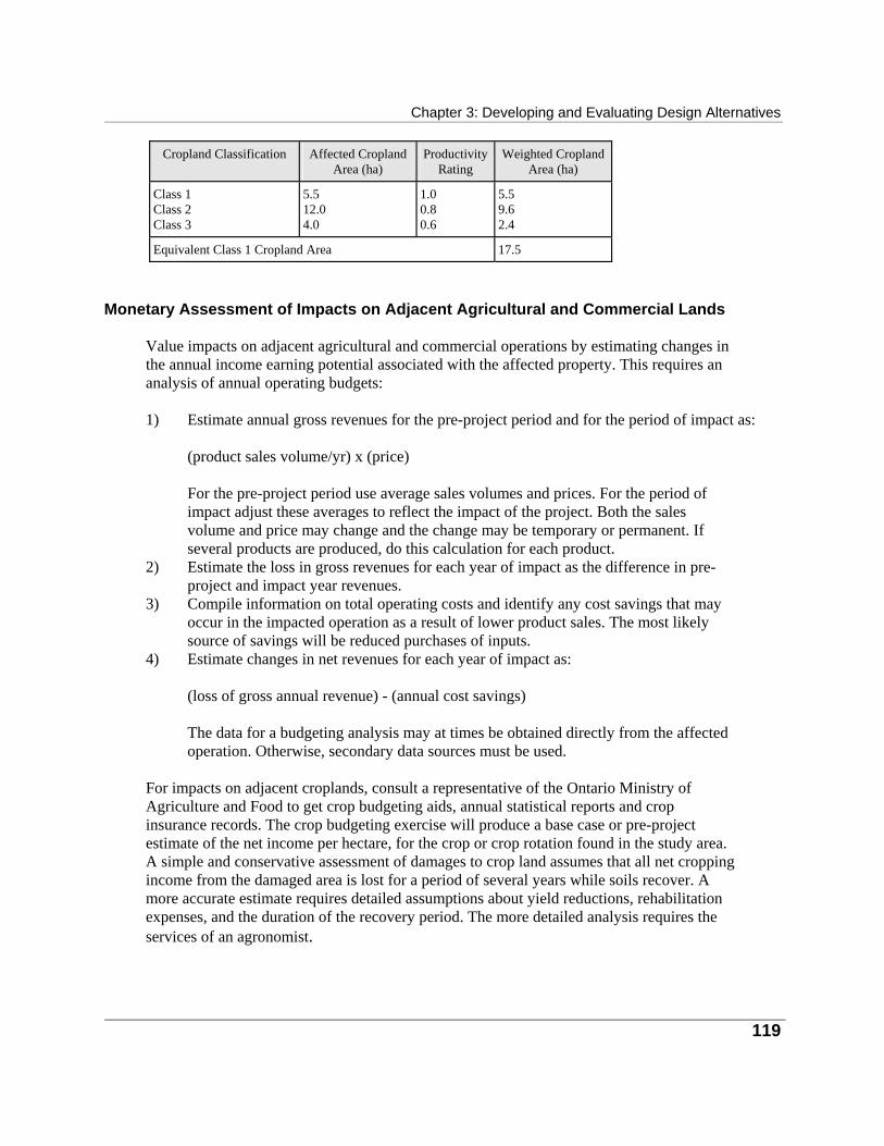
Chapter 3: Developing and Evaluating Design Alternatives
119
Cropland Classification
Affected Cropland
Area (ha)
Productivity
Rating
Weighted Cropland
Area (ha) Class 1 Class 2 Class 3
5.5 12.0 4.0
1.0 0.8 0.6
5.5 9.6 2.4
Equivalent Class 1 Cropland Area
17.5
Monetary Assessment of Impacts on Adjacent Agricultural and Commercial Lands Value impacts on adjacent agricultural and commercial operations by estimating changes in the annual income earning potential associated with the affected property. This requires an analysis of annual operating budgets: 1) Estimate annual gross revenues for the pre-project period and for the period of impact as:
(product sales volume/yr) x (price)
For the pre-project period use average sales volumes and prices. For the period of impact adjust these averages to reflect the impact of the project. Both the sales volume and price may change and the change may be temporary or permanent. If several products are produced, do this calculation for each product.
2) Estimate the loss in gross revenues for each year of impact as the difference in pre-project and impact year revenues.
3) Compile information on total operating costs and identify any cost savings that may occur in the impacted operation as a result of lower product sales. The most likely source of savings will be reduced purchases of inputs.
4) Estimate changes in net revenues for each year of impact as:
(loss of gross annual revenue) - (annual cost savings)
The data for a budgeting analysis may at times be obtained directly from the affected operation. Otherwise, secondary data sources must be used.
For impacts on adjacent croplands, consult a representative of the Ontario Ministry of Agriculture and Food to get crop budgeting aids, annual statistical reports and crop insurance records. The crop budgeting exercise will produce a base case or pre-project estimate of the net income per hectare, for the crop or crop rotation found in the study area. A simple and conservative assessment of damages to crop land assumes that all net cropping income from the damaged area is lost for a period of several years while soils recover. A more accurate estimate requires detailed assumptions about yield reductions, rehabilitation expenses, and the duration of the recovery period. The more detailed analysis requires the services of an agronomist.

MTO Drainage Management Manual
120
Data sources for the analysis of criteria related to commercial property impacts are not as complete as those for agriculture (the annual Statistics Canada publication, Market Research Handbook, Catalogue 63-224, provides small business financial statistics). The analysis of business income loss is usually left to an appraiser.
Flood Damages The initial analysis will involve mapping, site inspections to inventory the flood plain structures, and an examination of historical flow and flooding records. It may be possible to guesstimate total expected flood damages by extrapolating from earlier estimates for the study area. If it becomes clear that flooding is a significant risk that can be reduced, then average annual flood damages should be estimated for the base case and for each flood reduction option. The impact of each option is measured as the expected change in damages: (avg. annual damages after project) - (avg. annual damages before project) Methods to estimate average annual flood damages are fully documented in the report, Flood Damages: Volume 2 - Guidelines for Estimation, (Paragon Engineering, 1984; available from the Ontario Ministry of Natural Resources). Due to the extensive data required for full flood damage analysis, a non-monetary estimate of flooding potential is more appropriate at the study options stage. This can be measured as a count of the households and structures, and the area of lands classified by land use that are at risk in the flood plain. Example 3C.4: Measuring the Exposure to Flooding • The following example illustrates a flood exposure measure that takes probability of
flooding into account. • This measure does not account for the severity of flooding since the degree of
damage to each home is not estimated.
Flood Elevation (meters)
Probability of Occurrence
of Flood Flows
# Homes Exposed at
Each Flow Level
# Of Homes Multiplied by Probability of Occurrence
1005.0 1005.5 1006.0 1006.5
0.100 0.050 0.010 0.001
1 12 55 167
0.100 0.600 0.550 0.167
Annual Average Number of Homes Flooded
1.417
Chapter 3: Developing and Evaluating Design Alternatives
121
Other Impacts Related To Adjacent Property Other impacts on adjacent property include changes to the amenities provided by the property and its surroundings, and changes in the uses that can be made of properties. The changes may be beneficial or adverse. Beneficial effects will arise primarily as a result of flood reduction and erosion control. For example, the replacement of an undersized culvert with an adequate culvert at a stream crossing could lower the regional flood line above the culvert. This may ease restrictions on cut and fill activities or allow an expansion of gardening into new areas. Measures to control stream bank erosion can protect riparian property by preventing the loss of land to bank slumping. Identify and describe the expected beneficial and adverse effects on property uses and amenities at the study options stage and rate their significance as low, medium or high. If a monetary evaluation is also required, then the simplest approach involves assigning a fair market price to the lost amenities. This approach can be used in cases such as the loss of horticultural plants, since these can be valued based on the price of equivalent plants installed by a commercial nursery. In certain cases, the regional MTO property staff have standard values that they apply for purposes of valuation. At times the lost amenity is not replaceable. In such cases, value the losses by assessing how the property value would be affected by the loss of the amenity. Appraisers undertake the comparative analysis of property values that is required to assign value to these types of impact.
Travel Costs Travel costs will typically be a subject of concern for a parent highway planning project rather than the drainage and water management component of that project. However, travel costs or cost savings can be significant in a water management context if the options being considered involve longer routes. Longer routes may be required to avoid sensitive water resource features such as wetlands or cold water streams. Travel costs include vehicle operating costs and the value of time spent travelling. Vehicle costs will include only variable operating costs (fuel, depreciation, etc.). Example 3C.5: Measuring the Value of Travel Time • This example considers the cost to road users of a 1.0 kilometre diversion around a
wetland. In this example the following assumptions are made.
• The value of time in transit is estimated for all adults in a vehicle and their time is usually valued at 1/3 to 1/2 of their gross hourly earnings (Wage and income information are available from Statistics Canada).
• The hourly earning figure to use in the travel cost calculation is provincial average hourly income from employment for men and women. Hourly income data for

MTO Drainage Management Manual
122
industry are provided in the Statistics Canada Catalogue 72-002, Employment,
Earnings and Hours, and annual income data are provided in the Catalogue 72-002, Income Distributions by Size in Canada. Divide annual income data by 2000 hours/year to convert it to hourly data.
• The vehicle cost portion of a travel cost calculation is based on unit travel costs. Assuming a unit variable operating cost of $0.25/km, the annual cost on a highway with an annual average daily use rate of 1000 vehicles is:
Vehicle cost = ($0.25/vehicle.km) x (1 km) x (1000 vehicles/d) x (365 d/yr)
= $91,250/yr • The travel time portion of the calculation for this example, assuming an average of 1.2 adults per car and
an average hourly wage cost of $15, is as follows:
Value of travel time = (1/3 x $15/hr) x (1.2 persons/vehicle) x (1000 vehicles/d) x (365 d/yr) x (1 km)/(100 km/hr)
= $21,900/yr • The total annual travel cost for this example is:
Total annual cost = $91,250 + $21,900 = $113,150
Impacts on Recreation Recreation can be affected if the road work at a crossing creates (or destroys) sport fish habitat or if it makes the stream more accessible to people. Identify and describe such impacts using information from recreational user surveys, site inspections, key informant interviews, attendance records (in the case of managed park facilities) or recreation capacity calculations. Recreation activity is measured in user days of activity. In smaller studies, use a non-monetary valuation for recreation criteria. After recreation resources and activities have been described, assign a low, medium or high rating to the potential impact of each option. The monetary valuation of recreation criteria resembles unit costing except that the measures of recreational value are called user day values and not unit costs. User day values measure the value of the recreation activity to the user. The value of changes in user days is estimated as: (number of user days) x (user day value) User day values range from $10 to $30 for the more common outdoor recreation activities. These values are determined in socio-economic questionnaires.
Intangible values: Recreation is one of many use and non-use values that are called intangible because they are not priced in the market place. Others are health, safety and environmental quality. Questionnaires are used by economists to estimate intangible values.
Chapter 3: Developing and Evaluating Design Alternatives
123
The analysis of recreation criteria requires a background in economics or geography.
Equivalent Measures of Monetary Value The various dollar measures of costs and benefits for each option must be added up before options are compared. Before doing this make sure that the estimated dollar values are measuring “apples and apples” rather than “apples and oranges.” Dollar values will be commensurate when they: • are made over comparable life spans; • include full life cycle costs; • are based on the same inflationary price level; and • account for the time value of money.
Common Life Spans Project life spans will vary. For example, concrete structures and earth embankments may last 50 years or more while ditches may require major reconstruction every 10 to 20 years. A valid comparison can only be made between alternative projects when life spans are standardized to a common period. This period, commonly set at 50 years for water related projects, represents the minimum expected life span of long lived structural assets. It is also long enough that costs beyond the end point of the 50 year period have little effect on total values, once the time value of money is taken into account. Assume that projects that will not last for 50 years are periodically reconstructed over the planning horizon so that costs and benefits for all of the alternatives have the same duration.
Life Cycle Costing One option may have high up front capital costs and low OM costs while another may have low capital costs and high OM costs. A comparison based just on capital costs in this instance would be misleading since high OM costs over the life of one option are ignored. Use life cycle costing to avoid this problem. With life cycle costing, all recurring costs are forecast over the full planning horizon for every alternative. Life cycle costs include both up front capital costs and subsequent recurring costs. Recurring costs can include annual OM costs, and periodic repairs and replacements.

MTO Drainage Management Manual
124
Accounting for Inflation Costs are calculated using historical cost data. The historical data will vary systematically through time due to price inflation. Historical cost data must therefore be updated to a common year before calculating unit costs. Where unit costs are obtained from published sources, it is necessary to assure that they are all expressed in terms of the price levels of a common reference year. As a matter of convenience, the reference year for price levels is usually the year in which the costing analysis is done. Inflationary adjustments of historical values are made using an index of price levels. Price indices measure relative price movements over time. The calculation to update values to the reference year is:
PriceBref. year B = (PriceBhistorical yearB) x [(Price index Bref. Year B) ÷ (Price index Bhistorical
year B)] 3.1
The reference year for price levels is the most recent year for which price data and price indices are available. This is not the same as the base year or first year of the planning horizon for the study. The base year is usually a year in the near future following the planning period. No attempt should be made to inflate costs forward in time to the base year since reliable forecasts of inflation are difficult to make. It is not necessary to inflate project costs or benefits over the duration of the planning horizon since a general inflation factor will affect all costs and benefits equally. It therefore has no effect on relative costs and thus on the outcome of the evaluation. The estimating office of MTO routinely estimates construction cost price indices. Consumer price and construction cost indices are also available from Statistics Canada. Trade journals, such as the Engineering News Record and Chemical Engineering, publish construction cost indices as well, but these describe American prices and should not be used in Canada.
The Current Value of Future Dollars Costs and benefits occurring in different years should not be directly added because there is value associated with the passage of time. Future costs and benefits are not given as much weight as costs and benefits occurring today. The interest rate, expressed as an annual percentage, measures the time value of money. Future dollar values can be added once they have been converted to equivalent present day values or present values. The procedure used to estimate present values is called discounting. The discounting calculation is: PV = FVBnB ÷(1 + i) P
nP
3.2
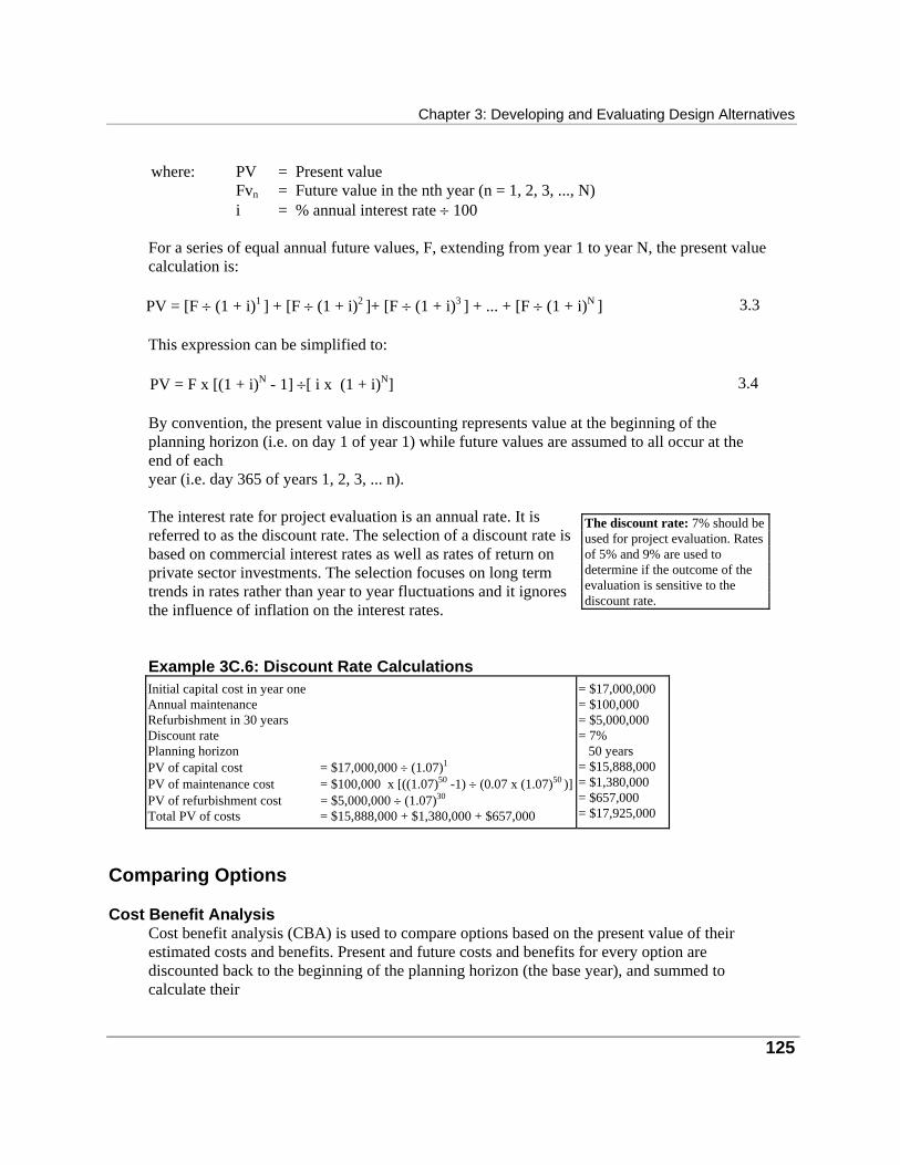
Chapter 3: Developing and Evaluating Design Alternatives
125
where: PV = Present value
Fv Bn B = Future value in the nth year (n = 1, 2, 3, ..., N) i = % annual interest rate ÷ 100
For a series of equal annual future values, F, extending from year 1 to year N, the present value calculation is: PV = [F ÷ (1 + i) P
1 P] + [F ÷ (1 + i) P
2 P]+ [F ÷ (1 + i) P
3 P] + ... + [F ÷ (1 + i) P
N P] 3.3
This expression can be simplified to: PV = F x [(1 + i)P
NP - 1] ÷[ i x (1 + i) P
NP] 3.4
By convention, the present value in discounting represents value at the beginning of the planning horizon (i.e. on day 1 of year 1) while future values are assumed to all occur at the end of each year (i.e. day 365 of years 1, 2, 3, ... n). The interest rate for project evaluation is an annual rate. It is referred to as the discount rate. The selection of a discount rate is based on commercial interest rates as well as rates of return on private sector investments. The selection focuses on long term trends in rates rather than year to year fluctuations and it ignores the influence of inflation on the interest rates. Example 3C.6: Discount Rate Calculations Initial capital cost in year one Annual maintenance Refurbishment in 30 years Discount rate Planning horizon PV of capital cost = $17,000,000 ÷ (1.07)P
1P
PV of maintenance cost = $100,000 x [((1.07)P
50P -1) ÷ (0.07 x (1.07) P
50 P)]
PV of refurbishment cost = $5,000,000 ÷ (1.07)P
30P
Total PV of costs = $15,888,000 + $1,380,000 + $657,000
= $17,000,000 = $100,000 = $5,000,000 = 7% 50 years = $15,888,000 = $1,380,000 = $657,000 = $17,925,000
Comparing Options
Cost Benefit Analysis Cost benefit analysis (CBA) is used to compare options based on the present value of their estimated costs and benefits. Present and future costs and benefits for every option are discounted back to the beginning of the planning horizon (the base year), and summed to calculate their
The discount rate: 7% should be used for project evaluation. Rates of 5% and 9% are used to determine if the outcome of the evaluation is sensitive to the discount rate.
MTO Drainage Management Manual present value. The present value of costs is subtracted from the present value of benefits to calculate the net present value (NPV) for each option: NPV of Benefits = (PV of Benefits) - (PV of Costs) 3.5 Net present values can be positive or negative. A negative NPV for an option means that the option can not be justified on the basis of its economic performance. For options with positive NPV’s, the one with the highest NPV is the preferred option. The benefit-cost ratio, an alternative summary measure in benefit cost analysis, is simply the ratio of costs to benefits where both are measured as net present values. It can be difficult to interpret and can be an unreliable measure. Do not use it.
Cost Effectiveness Analysis It is rarely possible to develop dollar measures of all costs and benefits. Frequently it is possible to value only the direct project costs and certain benefits related to cost savings or other readily valued effects. In this situation use cost effectiveness analysis (CEA) to compare options. For CEA, calculate the net present value of costs: NPV of Costs = (PV of Costs) - (PV of Monetary Benefits) 3.6 In a simple application, all of the options are equally effective in achieving non-monetary objectives and the option with the lowest NPV of costs is the preferred option. For this case, options which do not meet all of the objectives, including the do-nothing option, are eliminated before hand in this analysis. But life is rarely so simple and a straight forward CEA is not usually possible. In most planning studies, the NPV of costs becomes one of the entries in an impact matrix.
The Impact Matrix Summarize the criteria data developed in valuing the effects of study options in a table. The resulting “impact matrix” has as many data items as the number of criteria multiplied by the number of options. Dollar values in the impact matrix are reported as present values and costs and benefits are listed separately.
Cost Benefit Analysis and Cost Effectiveness Analysis alone usually give an incomplete picture of project impact. Combine the NPV of monetary costs and benefits with non-monetary impact data in the impact matrix.
Costs are shown as negative values while benefits and cost savings are positive. Depict non- monetary values in the impact matrix table as high/medium/low ratings and describe the associated rating scales in notes to the table. Check the first drafts of the impact matrix to determine whether there are any redundant
126
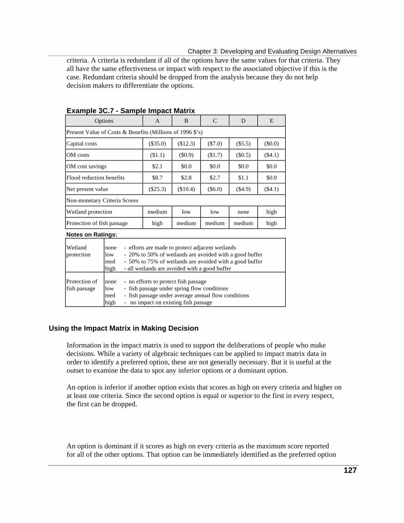
Chapter 3: Developing and Evaluating Design Alternatives
127
criteria. A criteria is redundant if all of the options have the same values for that criteria. They all have the same effectiveness or impact with respect to the associated objective if this is the case. Redundant criteria should be dropped from the analysis because they do not help decision makers to differentiate the options. Example 3C.7 - Sample Impact atrix M
Options
A
B
C
D
E Present Value of Costs & Benefits (Millions of 1996 $’s) Capital costs
($35.0)
($12.3)
($7.0)
($5.5)
($0.0)
OM costs
($1.1)
($0.9)
($1.7)
($0.5)
($4.1)
OM cost savings
$2.1
$0.0
$0.0
$0.0
$0.0
Flood reduction benefits
$8.7
$2.8
$2.7
$1.1
$0.0
Net present value
($25.3)
($10.4)
($6.0)
($4.9)
($4.1)
Non-monetary Criteria Scores Wetland protection
medium
low
low
none
high
Protection of fish passage
high
medium
medium
medium
high
Notes on Ratings: Wetland protection
none - efforts are made to protect adjacent wetlands low - 20% to 50% of wetlands are avoided with a good buffer med - 50% to 75% of wetlands are avoided with a good buffer high - all wetlands are avoided with a good buffer
Protection of fish passage
none - no efforts to protect fish passage low - fish passage under spring flow conditions med - fish passage under average annual flow conditions high - no impact on existing fish passage
Using the Impact Matrix in Making Decision Information in the impact matrix is used to support the deliberations of people who make decisions. While a variety of algebraic techniques can be applied to impact matrix data in order to identify a preferred option, these are not generally necessary. But it is useful at the outset to examine the data to spot any inferior options or a dominant option. An option is inferior if another option exists that scores as high on every criteria and higher on at least one criteria. Since the second option is equal or superior to the first in every respect, the first can be dropped. An option is dominant if it scores as high on every criteria as the maximum score reported for all of the other options. That option can be immediately identified as the preferred option
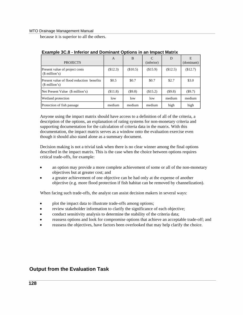
MTO Drainage Management Manual
128
because it is superior to all the others. Example 3C.8 - Inferior and Dominant Options in an Impact Matrix
PROJECTS
A
B
C
(inferior)
D
E
(dominant) Present value of project costs ($ million’s)
($12.3)
($10.5)
($15.9)
($12.5)
($12.7)
Present value of flood reduction benefits ($ million’s)
$0.5
$0.7
$0.7
$2.7
$3.0
Net Present Value ($ million’s)
($11.8)
($9.8)
($15.2)
($9.8)
($9.7)
Wetland protection
low
low
low
medium
medium
Protection of fish passage
medium
medium
medium
high
high
Anyone using the impact matrix should have access to a definition of all of the criteria, a description of the options, an explanation of rating systems for non-monetary criteria and supporting documentation for the calculation of criteria data in the matrix. With this documentation, the impact matrix serves as a window onto the evaluation exercise even though it should also stand alone as a summary document. Decision making is not a trivial task when there is no clear winner among the final options described in the impact matrix. This is the case when the choice between options requires critical trade-offs, for example: • an option may provide a more complete achievement of some or all of the non-monetary
objectives but at greater cost; and • a greater achievement of one objective can be had only at the expense of another
objective (e.g. more flood protection if fish habitat can be removed by channelization). When facing such trade-offs, the analyst can assist decision makers in several ways: • plot the impact data to illustrate trade-offs among options; • review stakeholder information to clarify the significance of each objective; • conduct sensitivity analysis to determine the stability of the criteria data; • reassess options and look for compromise options that achieve an acceptable trade-off; and • reassess the objectives, have factors been overlooked that may help clarify the choice.
Output from the Evaluation Task
Chapter 3: Developing and Evaluating Design Alternatives
129
The outputs from the evaluation task are: • summary recommendations concerning the preferred option and its implementation; • documentation of the evaluation process describing goals and objectives, evaluation
criteria, the options, their performance relative to each criteria, and the rationale for dropping options and selecting the preferred option;
• documentation of special technical studies for evaluation; and • documentation of the public consultation process describing the overall process, listing
the time and purpose of meetings and other activities, and reporting feedback from the public including comments about the options (correspondence, petitions, etc.).
Use of the Output Outputs from the evaluation task are used to inform decision makers about the nature of the planning problem and to guide them in making decisions. Beyond this, the outputs provide inputs to detailed site planning work, providing information and concepts that help to guide engineering design tasks. Evaluation outputs may also be used in the development of an implementation plan including the assignment of responsibilities, project scheduling, budgeting and finance. The estimation and valuation of project effects provides a basis for follow up monitoring and evaluation of the performance of water management measures that are implemented.