Embed Size (px)
Citation preview

4 J
J4 ENGINEERING PROJECTS LABORATORY3NGINEERING PROJECTS LABORATOR
4GINEERING PROJECTS LABORATO'~!INEERING PROJECTS LABORAT'
NEERING PROJECTS LABORAEERING PROJECTS LABOR
ERING PROJECTS LABO'RING PROJECTS LAB'
TNG PROJECTS LABIG PROJECTS LAB
PROJECTS LPROJECTF
ROJEC-OJEr
TT/
FORCED- CONVECTION CONDENSATIONINSIDE TUBES
Donald P. TravissAnton B. BaronWarren M. Rohsenow
Report No. DSR 72591-74
American Society of Heating, Refrigerationand Air Conditioning EngineersContract No. ASHRAE RP63
Engineering Projects LaboratoryDepartment of Mechanical EngineeringMassachusetts Institute of TechnologyCambridge, Massachusetts 02139
July 1, 1971

Technical Report No. 72591-74
FORCED-CONVECTION CONDENSATION INSIDE TUBES
by
Donald P. TravissAnton B. BaronWarren M. Rohsenow
Sponsored by:
Technical Committee 1.3
American Society of Heating, Refrigeration, and Air Conditioning Engineers
Contract No: ASHRAE RP63
DSR Project No: 72591-74
July 1, 1971
Heat Transfer LaboratoryMechanical Engineering Department
Massachusetts Institute of TechnologyMassachusetts Avenue, Cambridge, 02139

FORCED-CONVECTION CONDENSATION INSIDE TUBES
by
Donald P. TravissAnton G. BaronWarren M. Rohsenow
Massachusetts Institute of Technology
ABSTRACT
High vapor velocity condensation inside a tube was studied analy-
tically. The von Karman universal velocity distribution was applied to
the condensate flow, pressure drops were calculated using the Lockhart-
Martinelli method, and heat transfer coefficients were calculated from the
momentum and heat transfer analogy. Subsequently, the analysis was
reduced to an accurate, but simplified form, to facilitate calculations.
Experimental data for refrigerants R-12 and R-22 condensing in a
0.315 in. I. D. tube were obtained for mass fluxes from 1.2 x 10⁵ to
11.3 x 10⁵ lbm/hr-ft 2, qualities from 0.02 to 0.96, and saturation tem-
peratures from 75 to 140*F. On the basis of the data and analysis, a
simplified non-dimensional presentation of the results evolved. The
agreement between the majority of the data and the analysis was within
+ 15 percent.
110 u mw

Acknowledgement
The authors are grateful to ASHRAE Technical Committee TC 1.3
for support of this work.
IN Nfl,

Table of Contents
Abstract. . . . . . . . . . . . . . . . . .. .
Acknowledgment . . . . . .
Table of Contents. . . . .
Nomenclature.. . . . . . .
Introduction . . . . . . .
Experiment . . . . . . . .
General Description of
Test Procedure. . . .
Data Reduction. . . .
Analysis. . . . . . . . . .
Calculation Procedure
Results. . . . . . . . . .
Conclusions. . . . . . . .
References . . . . . . . .
Figures. . . . . . . . . .
Experimental Apparatus
Graph of B vs.6+ .
Graph of M vs. 6 +cri t
Graph of F2 vs. Re .
Baker Flow Regime Map
Comparison of AnalysiE
Comparison of AnalysiE
Appendix 1. Tables of Data
Appendix 2.........
Test Facility. . . . . . .
for Analytical Results.
.. .
.. . . . - - -
.. . . . . . .
.
and Heat Transfer Data ..
and Pressure Gradient Data
.
.
List of Relevant Variables for Computer Program .
Computer Program for Calculating Analytical Results
MININ111111",
. . . . . . 101

Nomenclature
A cross sectional area ft2
a axial acceleration due to external force ft/hr2
B buoyancy modulus
c specific heat BTU/lbm-0F
D tube inside diameter ft
E ratio of eddy conductivity to eddy viscosity
F0 defined in Eq. (16) lbf/ft 2-ft
F2 defined in Eq. (28a,b,c)
Fr Froude number
G mass velocity lbm/ft -hr
g0 constant: 4.17 x 10⁸ lbm-ft/lbf-hr2
h local heat transfer coefficient BTU/hr-ft - Fz
havg average heat transfer coefficient BTU/hr-ft 2-o F
h fg latent heat of vaporization BTU/lbm
K thermal conductivity BTU/ft-hr-0 F
L total length of condensation ft
M defined in Eq. (25)
Nu Nusselt number
dP/dz pressure gradient lbf/ft 2-ft
Pr Prandtl number
q/A heat flux BTU/hr-f t2
Re Reynolds number
S perimeter ft
T temperature 0F

AT difference between vapor and wall temperatures *F
U mean velocity ft/hr
uT friction velocity as defined in Eq. (21) ft/hr
v local axial velocity ft/hr
W mass flow rate lbm/hr
x quality
Xtt Lockhart-Martinelli parameter defined in Eq. (6)
y radial distance from the wall ft
z axial distance from condenser inlet ft
a void fraction
a ratio of interface velocity to average liquid velocity
6 thickness of the condensate film ft
S h eddy conductivity
Sm eddy viscosity
P absolute viscosity lbm/ft-hr
V kinematic viscosity ft 2/hr
p density lbm/ft 3
T shear stress lbf/ft2
SUBSCRIPTS
e exit
f friction
g gravity
k liquid
v vapor
z local value
0 wall
IM'.

6
INTRODUCTION
When saturated vapor flows in a tube that is cooled by an exterior
fluid, some of the vapor condenses on the tube wall and forms a liquid
film. Condensation inside tubes occurs in many applications, particu-
larly in refrigeration condensers. The main resistance to heat transfer
for refrigerants and other low-conductivity fluids is the resistance
to conduction through the condensate film.
The analysis of Nusselt [1] outlined the basic approach to this
problem. At low flow rates and velocities, a laminar condensate film
forms on the tube wall; and for a horizontal tube, the liquid
accumulates at the bottom. Experimental data for this situation are
in good agreement with the results [2], [3], and [4]. A turbulent
condensate film evolves at higher flow rates. This problem
has been studied by several investigators (for instance: Akers [5],
Chen [6], Soliman [7], and Patel [8], and the resulting correlations
have usually relied on empirical methods. Carpenter and Colburn [9]
derived a semi-empirical equation of limited application. Rohsenow
et al. [10] obtained the heat transfer coefficient for a liquid film
on a vertical flat plate by using the momentum and heat transfer
analogy. Later papers [11], [12], and [131 employed the same approach.
More recent developments by Bae et al. [14] and Kosky and Staub [15]
employed variations of the Lockhart-Martinelli pressure drop model.
In ideal annular flow, the condensate forms a film of uniform
thickness on the tube wall and the vapor flows in the interior core.
In practice, this pattern may be modified by waves, entrainment, and
stratification. However, these effects are hard to predict or

analyze, and annular flow is usually assumed to exist in the para-
metric range of interest. Since the vapor core is very turbulent,
radial temperature gradients are neglected. In addition, the tem-
peratures in the vapor core and at the liquid-vapor interface are
assumed to be equal to the saturation temperature. Axial heat con-
duction and subcooling of the liquid film are also neglected.
In the present paper, the momentum and heat transfer analogy is
applied to the annular model using the von Karman universal velocity
distribution to describe the liquid film. This seems to be the most
accurate method for describing the condensate flow and heat transfer.
An order of magnitude analysis and non-dimensionalization of this
theory result in a simple formulation for the local heat transfer
coefficient. The analysis is compared to experimental data and the
results are used to obtain a general design equation for forced-
convection condensation.
11016

8
EXPERIMENT
General Description of Test Facility
The basic apparatus is shown schematically in Fig. 1. It consisted
of a closed-loop refrigerant flow circuit driven by a mechanical-sealed
rotor pump. An electrically heated boiler generated vapor which passed
through a flow meter and into the test section. An aftercondenser
downstream from the test section condensed any remaining vapor and en-
sured liquid refrigerant at the pump inlet. The pump was connected to
a by-pass loop, and a valve in the by-pass loop was used to regulate
the flow rate and pressure in the test section. The return line from
the boiler incorporated a filtering-drying element and a commercial
sight glass and moisture indicator. Front and rear views of the experi-
mental apparatus are shown in Fig. 2.
The test section was a tube-in-tube heat exchanger: the re-
frigerant flowed through the inner tube and the water flowed counter-
currently in the annulus or jacket. The inner tube was a commercial
3/8 in. 0. D. (0.315 in. I. D.), continuous copper tube 16 1/2 ft. long
and extended 2 ft upstream from the test section.
Seven brass rings, each incorporating a pressure tap, were soldered
to the inner tube at 29 in intervals. These split the annulus length-
wise into six sections. Heat transfer and pressure drop measurements
were made in each of these sections. Adjoining sections of the water
jacket were connected in series by flexible hoses to ensure mixing.
Two differential thermocouples were located at the inlet and outlet of

each water jacket for measuring the temperature rise of the water
through each section. In addition, two differential thermocouples
were located at the first water inlet and the last water outlet in
order to check the overall water temperature rise against the sum of
the six individual water temperature rises. At the mid-point of each
section two thermocouples were installed: one on the outside wall
of the condenser tube and one at the centerline of the tube. The wall
temperature thermocouples were soldered flush to the outer surface of
the copper tube; and as such, did not project into the boundary layer
of the coolant. To install the centerline thermocouples, holes were
bored into the copper tube and open-ended stainless steel tubes,
0.035 in. O.D., were soldered in the holes. The tip of the stainless
steel tube was 1/64 in. short of the copper tube centerline. The
thermocouples were then inserted so that the thermocouple beads would
be at the centerline of the copper tube, subsequently the thermo-
couples were glued in place with epoxy. All the thermocouples were
made of 0.005 in. O.D. nylon-sheathed copper and constantan wire.
Downward-sloping copper tubes connected the pressure taps to a
U-tube mercury manometer through a manifold which enabled the measure-
ment of the refrigerant pressure drop through each section. A Bourdon
pressure gage, located upstream of the test section, was used to
measure the inlet saturation pressure.
Calibrated flowmeters were used to measure the flowrate of the
water through the annulus and aftercondenser. Thermocouples were also
installed to measure the temperature of the water at the aftercondenser

I0
inlet and outlet, and of the refrigerant at the inlet of the test
section and the outlet of the aftercondenser.
All the loop was insulated with fiberglass. The heat loss from
the test section to the atmosphere was not measurable within the
accuracy of the potentiometer.
Test Procedure
It was desirable to eliminate all possible contaminants before
charging the refrigeration loop. The loop was evacuated to 30 in.
Hg and filled with dry nitrogen repeatedly to eliminate moisture.
Then the system was evacuated and filled with the refrigerant vapor
until a pressure of 70 psig. was reached. The refrigerant was then
allowed to escape through bleed valves at the aftercondenser, boiler
return line, and manometer until the pressure fell to 5 psig. This
was repeated twice in order to dilute any traces of non-condensibles
in the system. The system was then charged with liquid refrigerant
until the sight glass in the boiler showed that the heating elements
were covered.
To obtain the desired conditions in the runs, several parameters
could be controlled. The temperature of the water entering the annulus
and the aftercondenser was controlled by mixing hot and cold feeds.
The water temperature, the water flow rates, the by-pass valve setting,
and boiler heat input determined the refrigerant temperature, pressure,
and flow rate. Data were taken one hour after the system had reached
steady state.

(I
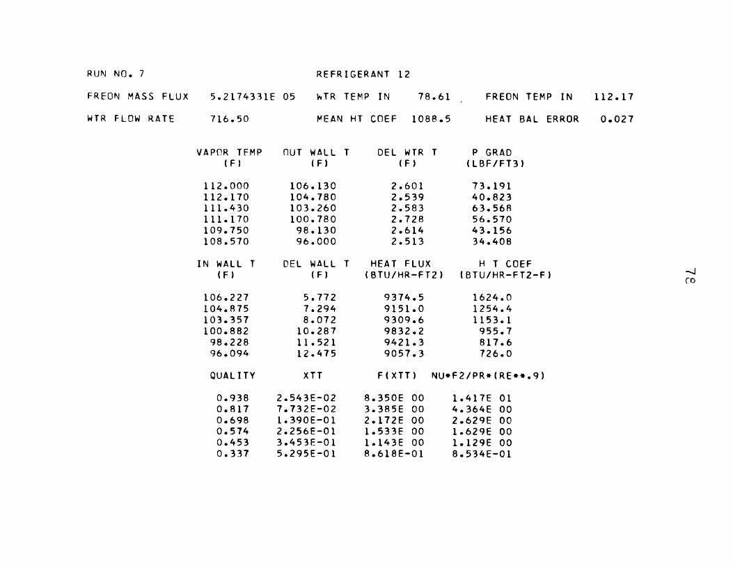
Data Reduction
An overall heat balance was performed for each run by comparing
the heat gained by the water with the heat lost by the refrigerant
in the test section and the aftercondenser. For all runs, the error
was less than 7 percent. The heat flux from the refrigerant was
obtained by multiplying the water flow rate by the water temperature
rise and specific heat. Using the thermal conductivity of the inner
tube, dimensions of the inner tube, and heat flux, the temperature
drops across the tube wall were calculated. From this information
the inside wall temperatures were determined. The refrigerant
qualities at the midpoints of the six sections were determined from a
heat balance using the thermodynamic properties of the refrigerant,
refrigerant flow rate, and heat gain of the water. The condensation
heat transfer coefficient was obtained by dividing the average heat
flux for a section by the difference between the vapor temperature and
inside wall temperature. The pressure gradient was calculated by
dividing the pressure drop across one section by the length of that
section.
0141,

ANALYSIS
The pressure gradient for two-phase flow in a pipe may be expressed
as the sum of three components:
(P) = (dP) + (dP) + (dP) (1)dz dz f dz g dz m
due respectively to friction, external body forces, and momentum
change. The components of the total pressure gradient are related
to wall shear stress, external acceleration and velocity gradients
as follows 14I:
dP ) = (2)
(-) = a [ap + (1- a) p ] (3)dzg g0 v
S1 dU W (4)dz m gA dz y v k
Assuming that condensation does not affect the frictional pressure
drop, the isothermal correlations are applied directly as was done by
Martinelli and Nelson (181 for boiling and by Bae 1 4 1 for condensation.
Following the method used by Lockhart and Martinelli 19 , the frictional
pressure gradient for two-phase flow is related to the pressure gradient
for vapor only by:

dPv 2 ddzci~ =v dz v
dP
X - )z=(PY )0. 9tt vPx) 11v xdz v
dP ) 4 0.045 2G x = 0.09iz- v D Re0.2 2o
V
0.2G 1.8 1.8v
g0 p D 1.2
The data of ref. [19] were given in an approximate curve by
Soliman et al."7 1 as follows:
= 1 + 2.85 X 523
combining Equations (5), (6), (7) and (8):
dP 0.09 (v )0.2(yz)f G~ 2 00 G D
G v
Pv
[1 + 2.85 [().1 1 - xO.9 _v 0.5 0.523 2[1[-- + 2.8 C1-),I I
The gravity component is re-written as follows:
dP g0D 1 9(-) = [ - Ba]dzgG 2 Fr 2pv
Pv
13
where:
and:
(5)
(6)(--Y)P P.
(7)
(8)
(9)
(10)

14
where:
G 2
Fr = vaD
is the Froude member based on the total flow and:
pt. - pvB = (12)
pv
is the buoyancy modulus. The local void fraction is calculated
using Zivi's equation[20].
a = --- -- (13)
1 + ( X v3x p .
Combining Eq. (13) with Eq. (4) and performing the indicated opera-
tions yields:
(-) =- D(j-) [2x + (1 - 2x) ( )dz m zP
PV (14)
2
+ (1 - 2x) (--) - 2(1 - x) ()]
For most of the tube length the liquid film is thin. At 20%
vapor quality the film thickness is less than 10% of the tube radius.

I5
Therefore a flat plate approximation is used for the liquid film.
The momentum equation for an element of the liquid layer yields:
o = F 06 + T (15)
where F includes pressure, momentum and gravity forces acting on
the film.
2 P 1
F dP + G dx 1 v30 dz g Z g0pv dz 1 - a p
(16)
(1 x)(2 - )
(1 - a) 2
3 is the ratio of the vapor-liquid interphace velocity to the
average velocity in the liquid film. This was obtained from the
universal velocity profile and is a function of 6+ as shown in Fig.
3. A more detailed description of the F and B terms can be found
in Bae[12]
Assuming that the von Karman momentum-heat transfer analogy is
applicable to the liquid layer, the shear stress and heat flux are
written as:
Pi dVT = (v + e ) (17)
g0 t m dy
_ =pq c (a + eh) dT (18)A t t t h dy
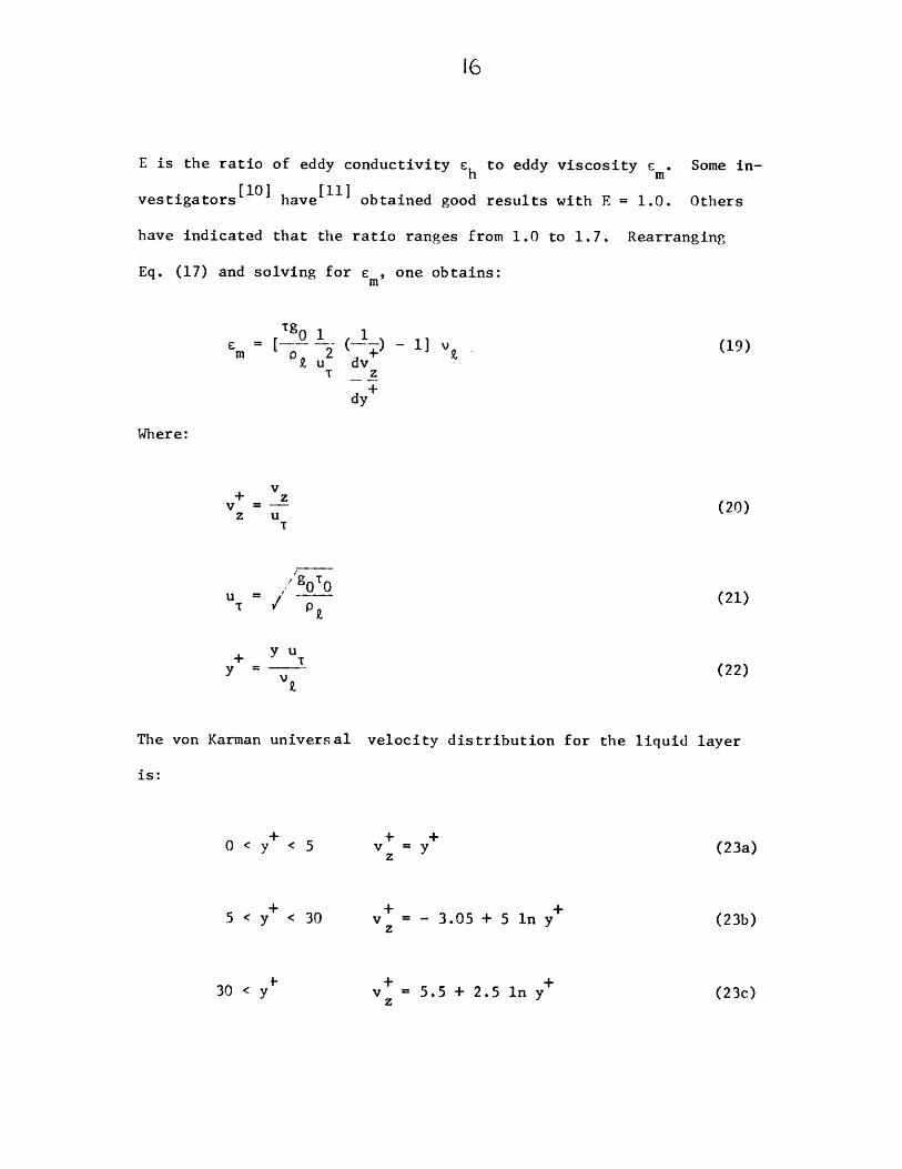
E is the ratio of eddy conductivity ch to eddy viscosity c m. Some in-
vestigators [10] have 11i obtained good results with E = 1.0. Others
have indicated that the ratio ranges from 1.0 to 1.7. Rearranging
Eq. (17) and solving for e , one obtains:
= 0 1 1m p 9,U2 v+
m 2u dvT z
dy+
- 1] v - (19)
Where:
+ 'zVz u
T
0 0U = / p
(20)
(21)
+ y uTy = (22)
The von Karman universal velocity distribution for the liquid layer
is:
0 < y < 5
5 < y < 30
30 < y
z = y
v += - 3.05 + 5 In y +z
v+ = 5.5 + 2.5 ln y +z
(23a)
(23b)
(23c)

17
Using Eqs. (19) and (23a, b, c), we obtain three expressions for
For the laminar zone em/v << 1 and T/T = 1; hence,
0 < y+ < 5 (24a)m
For the buffer zone, the eddy viscosity is of the same order of
magnitude as the kinematic viscosity and T/T 2' 1; hence,
5 < y < 30 Em = (vi) ({ - 1)
Assuming a linear shear stress variation in the turbulent zone
with T = F0 (6 - y) + v and e m/v >> 1, then:
30 < y S = [y + - ( +)2m 2.5 6+
(24c)
where:
0 u T T
Since (q/A) 2 (q/A) 0 , Eq. (18) may be integrated to yield:
1 T-T 0 +0 f' cdyh(q) Z c(a + cM)uTZ A 0
(25)
(26)
ED
(24b)
MMONININ I,, 1W.11111
U

18
Substituting Eq. (24) into Eq. (26) and completing the integra-
tion:
h D p C D uNu = -- - = - (27)
z k 9 2
where F2 is
0 < 6+ < 5
5 < 6+
30 < 6+
< 30
= 6 +Pr
F2 = 5Pr + ln(1 + EPr( - - 1))
F2 = 5F =5Pr + -ln(l +5EPr)
2 E
2.5
F /1 + lOME6 Pr
(28a)
(28b)
(28c)
2M-l+/ 1 + 1+in I___-E6 PCln2M- 1 1 + 10M
E6 Pr
60M
6+
60M
1 - 1 + -10M
E6 Pr
1+ 1+ OME6 Pr
The equations for F2 in the first two zones are fairly simple.
However the third term in Eq. (28c) involves a laborious calculation.

This term can be simplified, since 6' > 30, Pr > 3 for refrigerants
R-12 and R-22, and 0 < M S 1. Therefore:
1+ 10M < (10) ()
EPr 6+ (3) (30)1.11
Hence using a truncated binominal expansion as an approximation
of this factor would introduce an error of less than 0.05%, therefore:
/ 10M + + SM
EPr 6 EPr 6
And the third term of Eq. (28c) becomes:
+ 5M 60M 2 5M
2.5 EPr 6 6 EPr 6
1 + 5M 2M - 2 - 5M 60M + 5M
EPr 6 . EPr 6 EPr 6 ,
Which may be simplified and expressed as
2.5 K1+ 5M In
EPr 6 L
6+ EPr + 2.5 +30 EPr + 2.5]
(30 - 2.5 _-
6+ EPr
But since,
1< 1 + 5M < 1 + =5)(1) 1.0556-~ 6+ (1)(3)(30)

20
this factor may also be approximated as
+ 5M
EPr 6+
which introduces an error of less than 6 percent in the third term
of Eq. (28c) and a much smaller error in F2.
Also, 6 EPr > 30 EPr 2 30(1) (30) = 90
Hence 2.5 is neglected in comparison to EPr6 and 30 EPr. Since
2.5 is added to both the numerator and the denominator, the effect
of dropping it disappears for all practical purposes.
With these simplifications the third term becomes:
[M 2 25) 1+ (30 - ) - 1
2.5 ln[--] + 2.5 In (6+ EPr30 M (6+ 2.5)
-6+ EPr
and Eq. (29c) can be re-written as:
6 >30 25
F = 5Pr + - ln(l + 5EPr + 2.5 n( 6 + (302.5n -2 E r0 (le n + 2.5
6+ EPr
term 1 term 2 term 3 term 4 (29)
The fourth term of this expression represents the correction
due to the fact that 10 T. This term is negligible when the

21
quality gradient (dj) is not large. The calculation of the heat transfer
coefficient is greatly simplified when this term is negligible, since
the calculation of M depends on dx/dz which requires a laborious itera-
tion. The effect of M should be included if, in Eq. (29):
term 4 0.05 (term 1 + term 2 + term 3)
or:
H 2.5 -
(30 -) +
2.5 In[6 ] 2 0.25 [Pr + ln(l + 5EPr) + 6 ln( )M_( + 2.5) E 2 3
6 EPr
Solving this inequality for M, one obtains:
M M Mcrit
0.1 .lr(30)0 0 .lPr +1.05 + (0(I + 5EPr) E e . - 6
300.05
0.1 Olr0.1 0.lPrEeO.lPr + 1.05 2.5 EeO ~~ +0.05 2.5
(1 + 5EPr) 0- (6 ) --- (1 + 5EPr) E 0.0 (6 ) (30 EPr
300.05 EPr 30
Equation (30) gives the value of M for which an error of 5 percent
results if term 4 of Eq. (29) is dropped. Since the Prandtl number is
fixed for a given fluid and temperature, the value of 6 determines
M it. To determine whether the fourth term of Eg. (29) may be neglected,

22
one should calculate a test value of M from Eq. (25) with 6+ > 30 and
compare this value to Mcrit as determined from Eq. (30) or Fig. 4.
Fig. 4 is a plot of Merit versus 6 for several Prandtl numbers,
with E taken as unity. When the fourth term may be neglected, Eq.
(29c) reduces to the following:
6 > 30
F2 = 5Pr + ln(1 + 5EPr) + 2.5 ln( ) (31)
which is similar to the one presented by Kosky and Staub[15 ]. Other-
wise, it is best to use Eq. (29) in its entirety.
From the definition of 6+ and Re
6 += V (32)
Re = G(l - x) D (33)
Using continuity of mass the liquid Reynolds number may be written as:
6 6+
Re = -- p v dy = 4 v dy (34)12 y k z J z
0 0
Substituting Eq. (23) for v into Eq. (34) yields:z

23
6 < 5 Re. = 2(6+)
5 < 6 < 30 Re. = 50 - 32.26 + 206+ In 6+
6+ > 30 Re =-256 + 126+ + 106+ In 6
(35a)
(35b)
(35c)
Equations (35) may be approximated with an error of less than 4 per-
cent by straight line segments on a log-log graph. Using these
piecewise linear curve fits one can obtain 6 as an explicit function
of Re :
Re < 50 6+ = 0.7071 Re0.5t. Ik (36a)
50 < Rez < 1125, 6+ = 0.4818 Re0.5851 z.
(36b)
(36c)Re, > 1125,6+ = 0.095 Re0.8 1 2
t 2t
Equation (36) may be substituted in Eq. (31) to yield F2 as a function
of two accessible parameters, Re, and Prz:
Re -< 50 F = 0.707Pr Re0 .52 z z.
(37a)
50 < Re < 1125 F = 5Pr + 5 ln[l + Pr (0.09636Re0.585
2 z. k 2z
0.812Re > 1125 F = 5Pr + 5 ln(1 + 5Pr ) + 2.5 ln(O.00313Re )
2 23 2
(370)
(37b)

24
Equations (37a, b, c) are also presented graphically in Fig. 5 for
ease of calculation.
Substituting Eqs. (2), (9), and (21) into Eq. (27) and solving
for hz
0.2 1.8 1.8h 1 1 0 D .090 v G _x
z F 2CT F p k P 4 g 1.22 2 9. 0 ovDL
[1+ 2.85 0.1 1 - x 0.9 Pv0.5 2 2r-) (s) i f(-)'y
or simplifying:
h = 0.15z F
c 0.1 G 0 0.9 11 2.5 ) ' ( ~ 9 0.5 0.523c9.iv 0.1 x [l+2.85[- (ft-()
v Dx
(39)
Equation (39) may be rearranged in a more compact form by algebraic
manipulations and the definition of Xtt, Eq. (6), to yield:
-1 + 2.85 X-0.476tt tt
0.15 PrRe0.9-F Prk Z
or equivalently:
NuF2.9= F(Xtt
Pr Re0 .9
where F(Xtt) 0.15 [X- + 2.85 X-0. 476]1
(38)
(40)
(41)
(42)

25
Equation (40) is a good working equation since the right side is a
function only of Re and Pr (assuming the fourth term of Eq. (29)
may be neglected as previously explained). The value of Eq. (41)
is in correlating condensation data for different fluids or condi-
tions. In this case the heat transfer parameter (NuF2/Pr Re 0 )
may be plotted as a function of only one variable: Xtt'
The average overall heat transfer coefficient may be calculated
for the case of a constant temperature difference (Tvapor - Twall)*
If the temperature difference is not constant along the condenser
length, as is usually the case, then an average heat transfer
coefficient is of little use in determining the overall heat transfer
or condenser length since:
q/A) = (h AT) # h ATavg avg avg avg
Consider the heat transfer through the liquid layer:
dq = - Wh dx = h AT wD dz (43)fg z
Rearranging and integrating for constant AT yields:
1 AT WDLf =x (44)e z fgx
e
Where x eand L eare the exit quality and length. By definition:
11111101011IN I, I,

26
Le
- h dzavg Le j z0
and q = h AT rDL = Wh (1 - x ) (45)avg e fg e
Combining Eqs. (36) and (37):
11 1 dxh~~~~(= -x) (46)avg e z

27
Calculation Procedure for Analytical Results
Analytical heat transfer and pressure drop results were calculated
and compared with the experimental results with the same refrigerant
mass flux, saturation temperature, temperature difference, and tube
diameter. The calculations were accomplished in the following
manner:
1. Using the computer, the refrigerant properties were evaluated
at the average vapor temperature from a piecewise linear curve fit
of tabulated property values [16,17].
2. The quality was divided into 5 per cent increments starting
at 1.00 and decreasing to 0.05. The heat transfer coefficient
and pressure drop were calculated at each increment.
3. Xtt and Re were calculated from eqs. (6) and (33). F2
was evaluated using eq. (37) or Fig. 5. (The inherent assumption
in eq. (37) that M =0 will be checked later in step 11.)
4. The Nusselt number (Nu) and heat transfer coefficient
(h z) were calculated from eq. (41).
5. The friction pressure gradient was determined from eq. (9).
6. Since the condenser tube was horizontal, the gravity
pressure gradient was not calculated. For inclined tubes, the
gravity pressure gradient may be determined from eqs. (10) and (13).
7. The quality gradient ( ) was calculated from eq. (43):
d--h~ AT wDh z AT , using the values of h from step 4.W hfg z

28
8. The momentum pressure gradient was evaluated using eq. (14).
9. The total pressure gradient was determined from eq. (1).
10. 6+ was calculated from eq. (36).
11. For 6+ > 30, T and u T were determined from eqs. (2)
and (21). In addition F0 was calculated from eq. (16) with 6
obtained from Fig. 3. M was then calculated using eq. (25).
12. M as calculated in step 10 was compared to Mrit as
obtained from eq. (30) or Fig. 4. If M > Mrit then F2 was re-
calculated using eq. (29) and (36) instead of eq. (37). The heat
transfer coefficient was recalculated using the new value of F2
in eq. (41).
13. The increment of tube length (Az) required for a 5 per cent
quality change was determined from eq. (43):
W h (0.05)
h AT wDz
As discussed in the following chapter, the iterative steps
10 through 13 are not required if the quality gradient is small.
In particular, these steps were not needed for analytical calculations
based on the experimental data. This means that only steps 1 through
4 are needed to calculate the heat transfer coefficient for low
to moderate condensation rates.

29
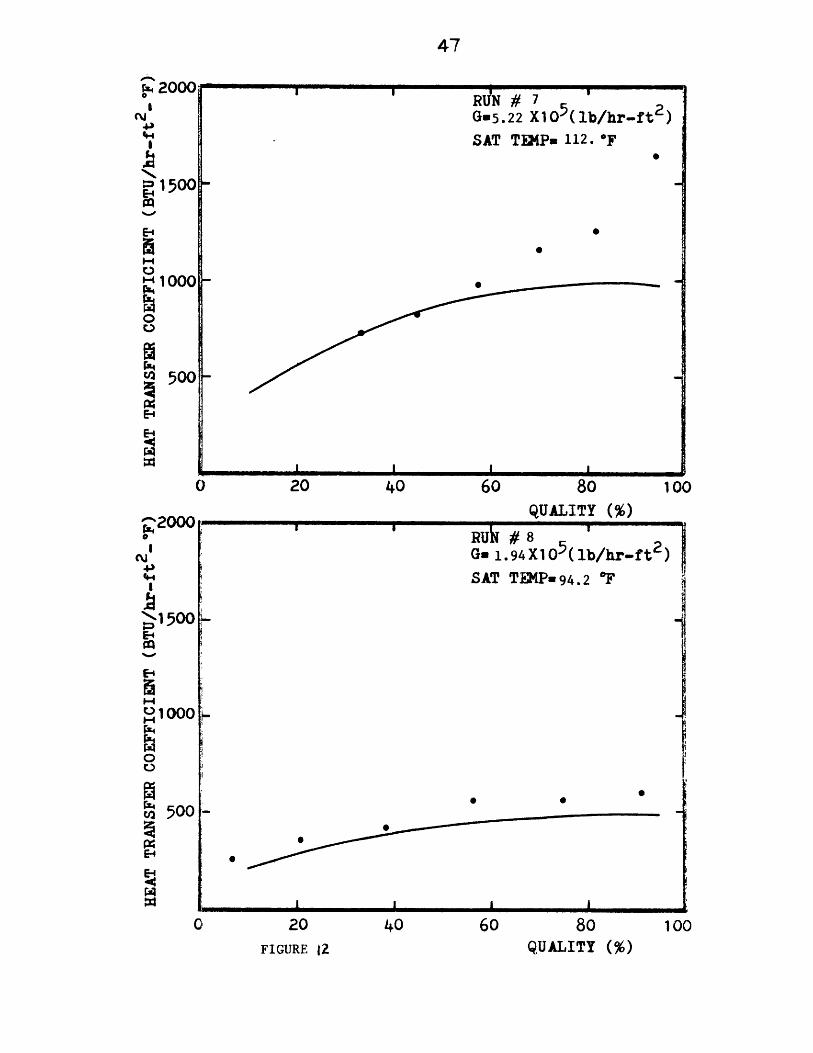
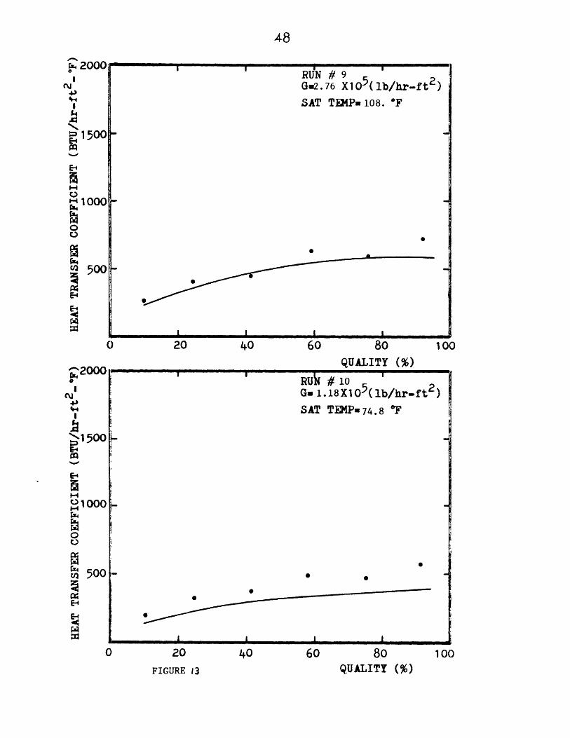
RESULTS
Sixteen experimental runs were made with refrigerant R-12 and
eleven runs were made with refrigerant R-22 for saturation temperatures
between 77 to 137*F and mass fluxes between 1.19 x 10⁵ lbm/hr ft2 and
6 21.13 x 10 lbm/hr ft2. The absolute value of the maximum heat balance
error for all runs was 7 percent. The data are presented in Appendix 1.
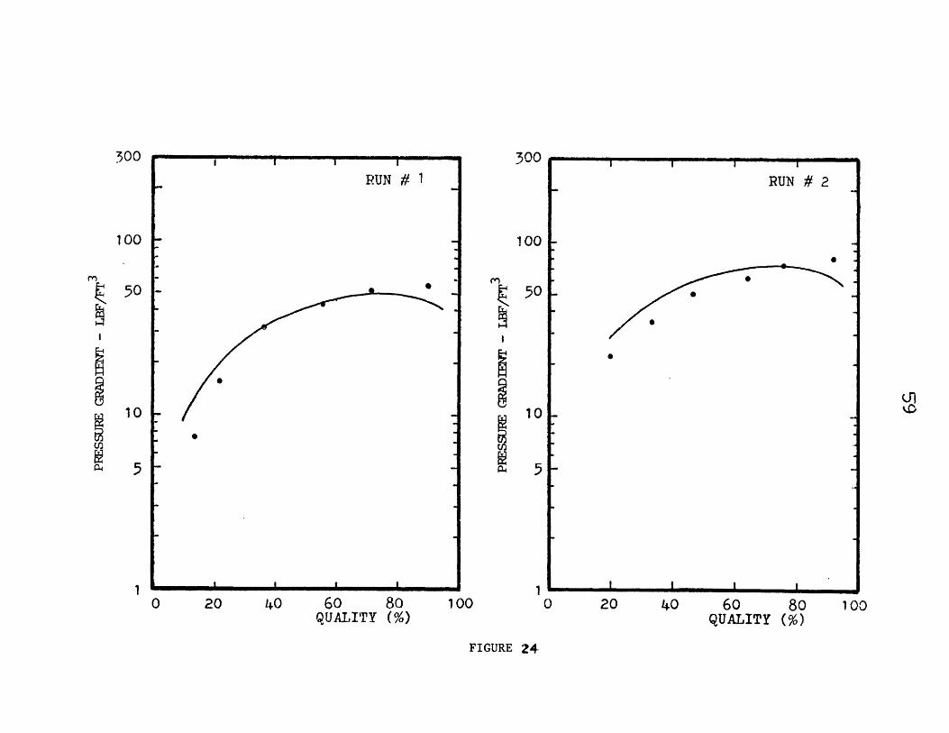
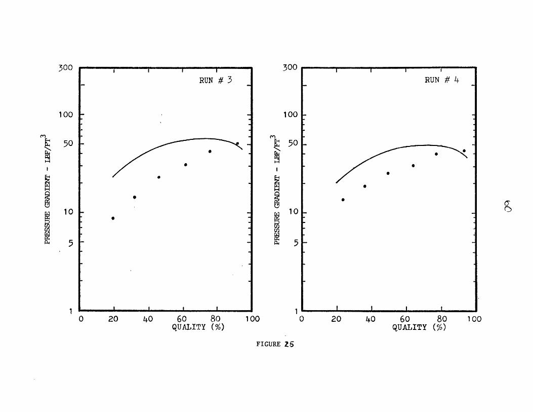
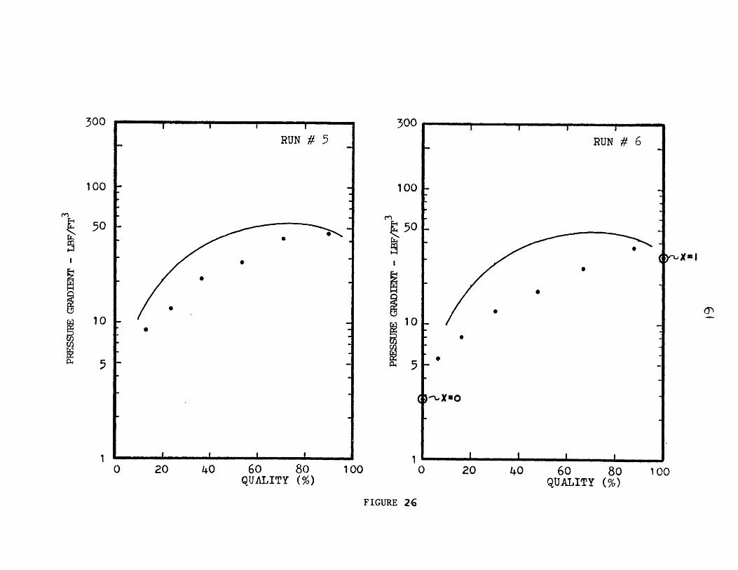
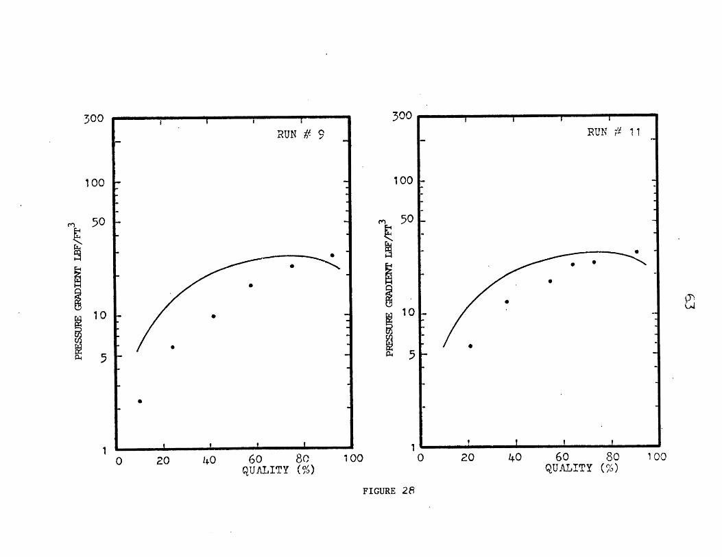
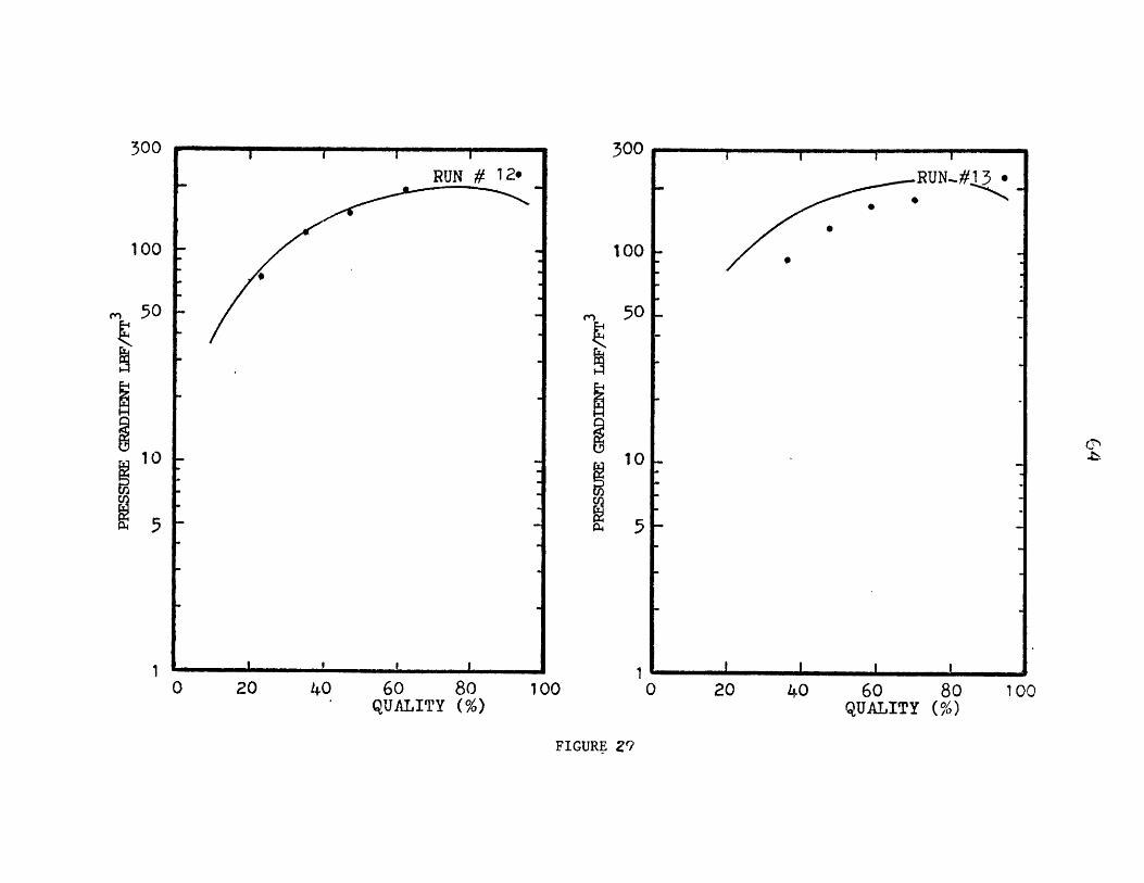
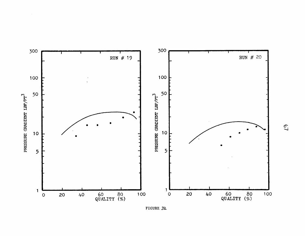
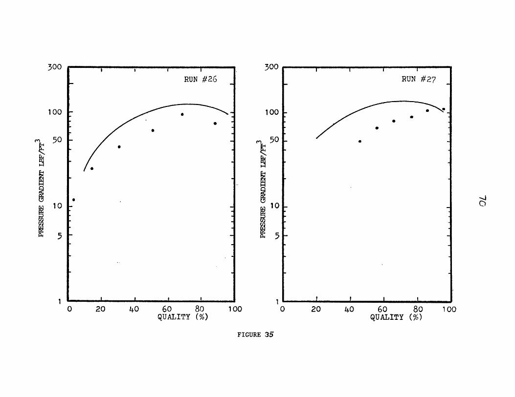
Figures 9 through 23 show the experimental and analytical heat transfer
coefficients while Figures 24 through 35 show the pressure gradient data.
Some experimental pressure gradient data (runs 3, 4, 6, and 19) were
omitted, because the sum of the individually measured pressure drops dif-
fered apprecially ( >15 percent) from the total pressure drop. Refri-
gerant R-12 was used for runs 1 through 16, and refrigerant R-22 was used
for runs 17 through 27. Analytical values of the local heat transfer
coefficients and pressure gradients were obtained using the procedure
outline in the proceeding section. One version of a computer program
used for these calculations is presented in Appendix 2.
It is important to know how often term 4 of Eq. (29) which includes
the effect of M was used. The ability to neglect this term with minimal
inaccuracy greatly simplifies the calculations. The effect of M was impor-
tant only 8 of the 27 runs, and then only for qualities less than 0.10
where the annular model is not applicable anyway. Previous data ob-
tained by Bae [12] for a 1/2 in. I. D. tube were also checked: the term
involving M was even less important for Bae's data. Hence, one can
neglect term 4 of Eq. (29) for conditions similar to the experimental
runs of Bae and the present authors. For higher condensation rates (higher
heat fluxes and quality gradients) this term becomes important and has
the ultimate effect of lowering heat transfer coefficient. In these cases,

30
Eq. (29) should be used in its entirety..
In the derivation of the heat transfer coefficient, no restrictions
were placed on the position of the condenser tube. Although in the
present work data were determined from measurements with a horizontal
tube, this analysis has an applicability to inclined tubes. The value
of E (ratio of eddy conductivity to eddy viscosity) was taken to be
1.0 for the curves of Figures 9 through 23. Calculations with E values
of 1.1 and 1.4 were also compared to experimental data, but no definite
trends were observed.
Since the analysis was developed for annular flow, departures from
this flow regime are presently examined. When the mass flux of the re-
frigerant vapor exceeded 500,000 lbm/hr ft2 there was appreciable en-
trainment of liquid in the first portion of the condenser tube. Physi-
cally this occurred because the vapor had a sufficiently high velocity
to pick liquid up off the wall and transport it as droplets in the vapor
core. At these high mass fluxes, the thickness of the liquid layer de-
creased due to entrainment, and consequently, the heat transfer coeffi-
cient increased. Since the present analysis assumes that annular film
condensation exists and that all of the liquid is on the tube wall, the
analytical predictions were below the experimental data in this misty
flow regime. This effect is shown by Figures 15, 16, 17, 22 and 23.
Entrainment usually occurs only in the inlet region of the condenser tube,
because the vapor velocity progressively decreases as additional conden-
sation occurs. The existence of entrainment was also substantiated by
plotting the experimental runs on a Baker flow regime map [21] as shown
in Figure 6, and also by high speed photographs through the glass sight
tube.

With the exception of high qualities and mass fluxes, the liquid
annulus was usually thicker at the bottom of the tube than at the top.
However, the analytical predictions compared well with the experimental
data, because a compensating effect existed between the increased heat
transfer in the upper portion and decreased heat transfer in the lower
portion. At qualities of less than 0.10, the flow was observed to be
in the slug flow regime. Experimental data obtained at low qualities
(runs 1, 6, 8, 10, and 24 on Figures 9, 11, 12, 13, and 22) show good
agreement with the analytical predictions in the neighborhood of 0.10
quality. At qualities appreciably below 0.10, a linear extrapolation
between the present heat transfer equation (Eqs. 39, 40, or 41) at
x = 0.10 and a single phase heat transfer equation gives a good estimate
of the heat transfer coefficient.
On the basis of Eq. (41), all of the experimental data for refri-
gerants R-12 and R-22 were reduced using the non-dimensional parameters
Nu F 2/Pr Re 0'9 and F(X tt) = 0.15 [X + 2.85 Xtt-0.4761. These data
(approximately 160 data points) are presented in Fig. 7 along with the
predicted values from the annular flow model (the straight line). Pre-
vious data from Bae [12] for R-22 are shown on a similar plot in Fig. 8.
As observed from Figures 7 and 8, these non-dimensional parameters
correlate a wide range of data very well. The experimental data and
analysis are in excellent agreement for F(X tt) < 2 (or Xtt < 0.155). For
F(X tt) > 2 the data are somewhat higher than the analysis predicts. Con-
sequently, these data are represented better by the dotted line of Fig. 7,
which may be expressed as:
Nu F2 1.15. rz ek= [F(X tt)] (47)
Pr Re - tt
l ollosill III Ali

32Nu F
One of the reasons for the higher value of whenX >2is thePr Re 0.9 tt
entrainment effect previously discussed. Even for F(X tt) > 2 the non-
dimensional parameters correlate the data well. This indicates that the
two curves drawn through the data points of Fig. 7 should be a good design
criterion for a wide range of conditions and flow regimes.

33
CONCLUSIONS
1. For the practical range of refrigerant condenser operating con-
ditions the simplified analysis developed here is applicable.
2. Recommended design equations for the local heat transfer coeffi-
cient in refrigerant condensers are as follows:
0.1 < F(Xtt ) < 1
1 < F(X tt) < 15
Nu F 2 = F(X
Pr Re = Ftt
Nu F 2 1.15Pr Re = [F(Xtt)]
where F2, Xtt and F(Xtt) are given by Eqs. (37), (6) and (42).
3. Pressure drop may be calculated by Eq. (1) with Eqs. (9), (10)
and (14).
+ 15%
34
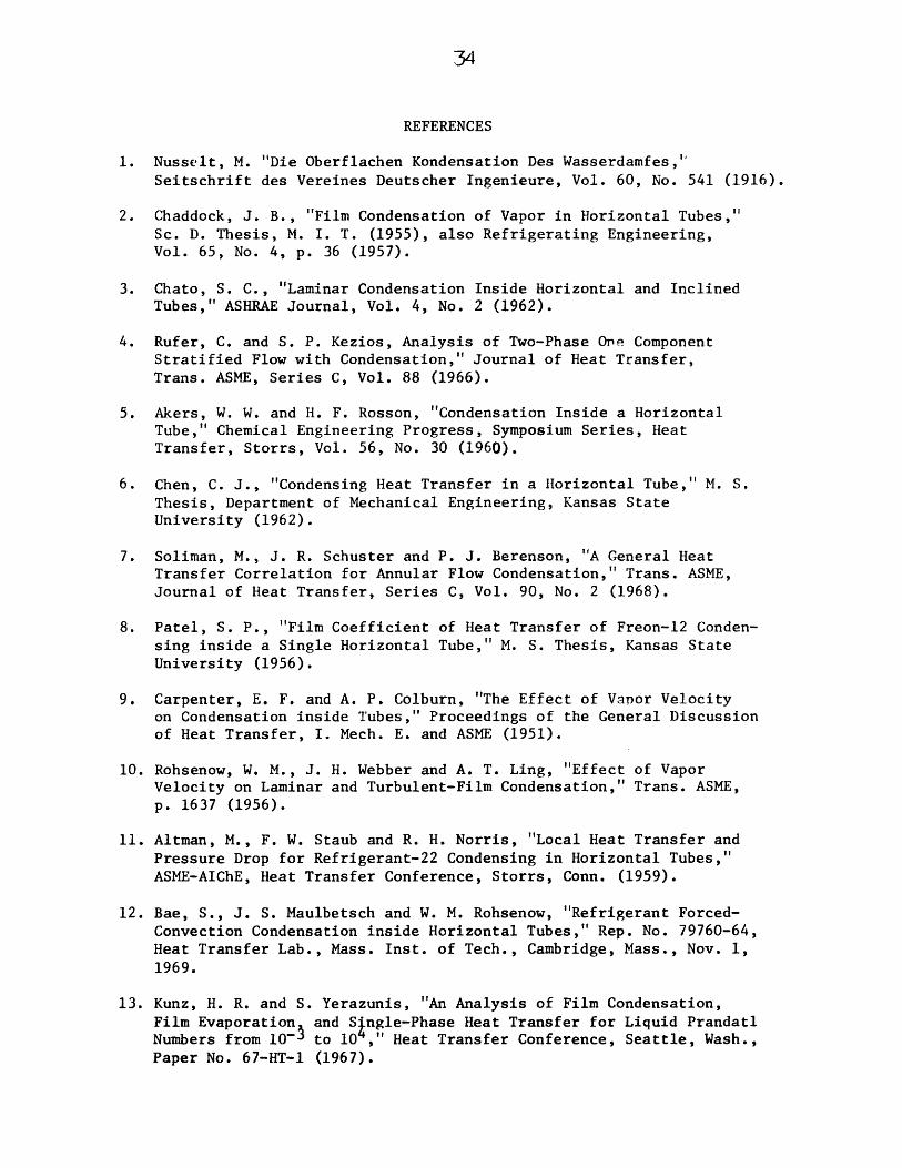
REFERENCES
1. Nusselt, M. "Die Oberflachen Kondensation Des Wasserdamfes,Seitschrift des Vereines Deutscher Ingenieure, Vol. 60, No. 541 (1916).
2. Chaddock, J. B., "Film Condensation of Vapor in Horizontal Tubes,"Sc. D. Thesis, M. I. T. (1955), also Refrigerating Engineering,Vol. 65, No. 4, p. 36 (1957).
3. Chato, S. C., "Laminar Condensation Inside Horizontal and InclinedTubes," ASHRAE Journal, Vol. 4, No. 2 (1962).
4. Rufer, C. and S. P. Kezios, Analysis of Two-Phase One ComponentStratified Flow with Condensation," Journal of Heat Transfer,Trans. ASME, Series C, Vol. 88 (1966).
5. Akers, W. W. and H. F. Rosson, "Condensation Inside a HorizontalTube," Chemical Engineering Progress, Symposium Series, HeatTransfer, Storrs, Vol. 56, No. 30 (1960).
6. Chen, C. J., "Condensing Heat Transfer in a Horizontal Tube," M. S.Thesis, Department of Mechanical Engineering, Kansas StateUniversity (1962).
7. Soliman, M., J. R. Schuster and P. J. Berenson, "A General HeatTransfer Correlation for Annular Flow Condensation," Trans. ASME,Journal of Heat Transfer, Series C, Vol. 90, No. 2 (1968).
8. Patel, S. P., "Film Coefficient of Heat Transfer of Freon-12 Conden-sing inside a Single Horizontal Tube," M. S. Thesis, Kansas StateUniversity (1956).
9. Carpenter, E. F. and A. P. Colburn, "The Effect of Vapor Velocityon Condensation inside Tubes," Proceedings of the General Discussionof Heat Transfer, I. Mech. E. and ASME (1951).
10. Rohsenow, W. M., J. H. Webber and A. T. Ling, "Effect of VaporVelocity on Laminar and Turbulent-Film Condensation," Trans. ASME,p. 1637 (1956).
11. Altman, M., F. W. Staub and R. H. Norris, "Local Heat Transfer andPressure Drop for Refrigerant-22 Condensing in Horizontal Tubes,"ASME-AIChE, Heat Transfer Conference, Storrs, Conn. (1959).
12. Bae, S., J. S. Maulbetsch and W. M. Rohsenow, "Refrigerant Forced-Convection Condensation inside Horizontal Tubes," Rep. No. 79760-64,Heat Transfer Lab., Mass. Inst. of Tech., Cambridge, Mass., Nov. 1,1969.
13. Kunz, H. R. and S. Yerazunis, "An Analysis of Film Condensation,Film Evaporation and S ngle-Phase Heat Transfer for Liquid PrandatlNumbers from 10~ to 10 ," Heat Transfer Conference, Seattle, Wash.,Paper No. 67-HT-1 (1967).

14. Bae, S., J. S. Maulbetsch and W. M. Rohsenow, "Refrigerant Forced-
Convection Condensation inside Horizontal Tubes," Rep. No. DSR72591-71, Heat Transfer Lab., Mass. Inst. of Tech., Cambridge, Mass.,Nov. 1, 1970.
15. Koskyk P. G. and F. W. Staub, "Local Condensing Heat TransferCoefficients in the Annular Flow Regime," presented at AIChE
63rd Annual Meeting, Nov. 1970.
16. "Thermodynamic Properties of Freon-12," DuPont (1956).
17. "Thermodynamic Properties of Freon-22," DuPont (1964).
18. Martinelli, R. C. and D. B. Nelson, "Prediction of Pressure DropDuring Forced Circulation Boiling of Water," Trans. ASME, Vol. 70,pp. 652-702 (1948).
19. Lockhart, R. W. and R. C. Martinelli, "Proposed Correlation of Data
for Isothermal Two-Phase, Two-Component Flow in Pipes," ChemicalEngineering Progress, Vol. 45, No. 1, p. 39 (1949).
20. Zivi, S. M., "Estimation of Steady-State Steam Void-Fraction byMeans of the Principle of Minimum Entropy Production," Journalof Heat Transfer, Trans. ASME, Series C, Vol. 86, p. 247 (1964).
21. Baker, 0., "Simultaneous Flow of Oil and Gas," The Oil and GasJournal, Vol. 53, pp. 185-195 (1954).

H 20 OUT H2 OlIN
FIGURE 1 SCHEMATIC DIAGRAM OF APPARTUS
H 20 OUT
ER
H 20 IN

37
FRONT VIEW
REAR VIEW
FIGURE 2 EXPERIMENTAL APPARATUS

2.5
2.0
1.5
1.05 10 20 50 100 200 500
FIGURE 3 GRAPH OF 6 VERSUS 6+
1000

1.0
0.9
0.8
Mcrit
0.7 - r = 5
Pr = 4
0.6 Pr = 3
Pro= 2.5
0.530 50 100 6+ 500 1000
FIGURE 4 M VERSUS 6 AT CONSTANT PRANDTL NUMBERcrit

102
Re z
FIGURE 5 GRAPH OF F2 VERSUS Re AT CONSTANT Prk

10
103
1 10 102 (G/G,)AO'FR10
FIGURE 6 BAKER FLOW REGIME MAP OF R-12 RUNS
105
10

42
e-Refrigerant R- 21.1 < G x 10
0.07 < x75 < T
, I.D. = 0.315 i.< 11.3 lbm/hr ft< 0.95< 140 F
6 < AT < 20 F
0 - Refrigerant R: 2, I.D. = 0.315 in.1.4 < G x 10 < 7.4 lbm/hr ft2
0.02 < x < 0.96
Nu F2
Pr Re 0.9
Nu F2
Pr Re 0.9
F(Xtt) = xtt - + 2.85
/
[F (t l1.15[F(Xtt]*1
82 < T < 118 F3 < AT < 27 F
0
0
s0g% **
* 0 00 .
teo 000*o
-0.476xtt0.1 1-x 0.9 p 0.5
xt p= x4 pt)
0.5 10 20
F(Xttd
FIGURE 7 COMPARISON OF ANALYSIS AND PRESENT CONDENSATION DATA
501-
10 I-
ON
rx4
z -p.4
1
F(Xt )
0.5 1-
0.1
* *
o0-.

43
o- Refrigerant R-22, I.D. = 0.493 in.
2.4 < G x 10-5 < 4.85 lbm/hr f t2
0.17 <81 <
9.6 <
< 0.96< 103 F< 19.5 F
/0
0.5 10 20
F(Xtt)
FIGURE 8 COMPARISON OF ANALYSIS AND BAE'S CONDENSATION DATA
50 1-
10 F-
5
osN O
z
0.5
0.1

44
2000
RUN # f 2Go 3.21X10 5 ( lb/hr-ft 2 )4.)
SAT TEMPs 80.2 *F
1500-
-1000 -*-
0 eS
U 500
I I I I
O 20 40 60 80 100QUALITY (%)
20-.?00#
Go 4.41X10 5 (lb/hr-f t 2 )SAT TEMPioi. *F
1500 -
E-4
01000
500
0 20 40 60 80 100FIGURE 9 QUALITY (%)

45
p2000 R-N-# 3
G. 32 X105(lb/hr-ft2 )
SAT TE1P= 120.*F
1500'-
00I-IC. *
P4 1000
00
ra
c500
E-4
0 20 40 60 80 100
2000 QUALITY (%)* 2 RUN # 4
GO4.26 X10 5 (lb/hr-ft 2 )4-3 SAT TEMPu 135.F
1500
01000 e
0
0 500 -
E-4
0 20 40 60 80 100FIGURE 10 QUALITY (%)

2000 " - -- -
Go 3.85X10⁵(lb/hr-ft 2 )SAT TEMP=101. ,F
1500
E-4
1000
0
500
E-4
o 20 40 60 80 100
-2000 QUALITY (%)
RUk1# 6G= 4.17 X10 5 (lb/hr-f t 2 )
4JSAT TEMPn127. *F
1500E-4
E-
1000
W 500 -
2-4|-4
o 20 40 60 80 100QUALITY (%)FIGURE 11
47
2000 RUN #7
G=5.22 X10⁵(1b/hr-f t2)SAT TElPw 112. *F
1500
S
6E-4
1000
0
500
E-4
rL
0 20 40 60 80 100
QUALITY (%)~2000*
CQG= 1.94 X10⁵(1b/hr-f t2)SAT TEMPu94.2 *
1 500
01000
S500 -
E-4
0 20 40 60 80 100QUALITY (MFIGURE 12
48
2000 -RUN # 9 f2Gm2.76 X10 5 (lb/hr-ft 2 )
SAT TEMP.108. *F
1500
1000
0
500-
EA
O 20 40 60 80 100
QUALITY (%)'2000 1
Nj Go 1.18X10 5 (lb/hr-ft 2 )
SAT TEMP.74.8 *F
1500
-4
~1 ooj-
0
500-
0 20 40 60 80 100
QUALITY (%)FIGURE 13

2000
N4-)
-1500
E-4
A
1000
0
~500
E-4
60 80QUALITY (%)
100
49
RUN # 11)--Go 2.81 X10⁵(lb/hr-ft2)
SAT TEMP=107. *F
-S
- -
- -
20 40

4000
cj G. 6.6 X10 5 (ib/hr-f t2)-)
SAT TEMP=81.0 *F
3000
%-04
f 2000
e
0e0
2 1000
ra
0 20 40 60 80 100QUALITY (%)
4000AN#3----T
N Ge 7.63X10⁵(lb/hr-ft2-p
SAT TD(Pw94.5 'F
3000
tE4
2000ra.
1000
E4
0 20 40 60 80 100FIGURE 15 QUALITY (%)

SI
4000
cm I Go 9.09 Xl 05(lb/hr-f t 2 )SAT TEMP=112. *F
1
3000-E-40
2000 -
0
1000
E
0 20 40 60 80 100QUALITY (%)
4000 RN#1G4.16 X105(lb/hr-ft 2 )SAT TEMPw140. *F
3000
E-4
F 2000rk
00
00
uL 1000 -
E4
0 20 40 60 80 100FIGURE 16 QUALITY (%)

52
-4000
3000E4E.-4
2000
I
1000
E40
Gu11.3 X10 5 (lb/hr-ft2 )
SAT TEKP=124. *F
20 60 80QUALITY (%)
100

53
S2000RUN #17 ( h t2 )G.2.57 X105(1b/hr-
SAT TEMPw 96.8 *F
1500
1000-
0
o 00
500-
E-4
O 20 40 60 80 100
02000 QUALITYRUk ~18Go 2.47 X10 5 (lb/hr-f t 2 )
.4-3SAT TEMPn85.0 'F
~1500O
'1000 -500 -
E-4
01000|
-4
0u
U) 500
E-4
0 20 40 60 80 100QUALITY (%)FIGURE 18e

54
S2000RUN #19Gw2.53 X10 5 (lb/hr-ft2 )
SAT TEMP1oo. *F
1500
E-4
r,
1-4 1000 0
0 20 40 60 80 100)
0-200QUALITY(%20000
N I GO 2.23 X10⁵(lb/hr-ft2)44 SAT TEMP=118. *F
%100
1500E-4
1000 --
Je
0 20 40 60 80 100QUALITY (%)FIGURE 19

55
2000RUN #21Gl.39 X10 5(lb/hr-ft2
SAT TEMP. 93.4 *F
1500
E-4
1000
0Uer4
500 -
E-4
0 20 40 60 80 100
QUALITY (%)2000 # 22
Go1. 47 X 105(lb/hr-f t 2 )4- SAT TEMP. 93.3*F
1500E-4
E-4
01000 --
S500 -
E-4
0 20 40 60 80 100
FIGURE 20 QUALITY (%)

RUN #23Gl.50 X105(1b/hr-ft2)
20001
21500
E-4
1000
0
500-
E4
80
QUALITY (%)
56
SAT TEMP. 82.9 *F
*
*0
*
20 40 60 100

-- 4000
Gu7.39 X105(lb/hr-ft2
SAT TEMPs 81.8 *F
3000
He
u 2000
P0
r 1000
E-4
0 20 40 60 80 100QUALITY (%)
4000 1
G.5.96 Xl05(lb/hr-ft 2
SAT TEMP. 96.4 0F
3000
E-4
rX40l 0
0
00
rx4
0 20 40 60 80 100FIGURE 22 QUALITY

58
4000
3000
0 2000a
P-4
003000
2 2000
01:)
cz
E4
0
00
I
S3000
-4
F2000
0
r%4C1000
EH
p
0
20 40 60 80QUALITY (%)
100
20 40 60 80 100FIGURE Z3 QUALITY (%)
RtN #26 - I2Gm 5.89 X 10⁵( lb/hr-ft2
SAT TEMP= 89.0*F
41
RUN # 1
0 20 40 60QUALITY
80(%)
300
100
100
RUN # 2
0 -
20 40 60 80QUALITY (%)
100
FIGURE 24
300
00
50
10
5
LO
50
10
5
RUN # 3300
100
RUN # 4
50
10
5
40 60QUALITY
80(%)
50
10
5
100 20 40
FIGURE ZS
300
100
(~1~
N
0 20
*
0
S
60QUALITY
80(%)
100
RUN # 5
40 60QUALITY
80(%)
100 20 40 60QUALITY
FIGURE 26
100
P4z
50
10
5
100
50
10
'5
0 20 10080(%)
300 300

RUN # 7
0 20 40 60QUALITY
80(%)
100 20 40
FIGURE 27
300
100
50
10
5
60QUALITY
10080(%)
300
100
50
10
5
RUN # 9300
100
50
10
5
RUN # 11
0 20 140 60QUALITY
80(%)
100 20 40 60QUALITY
FIGURE 28
300
100
rZ
50
10
5
10080(%)
RUN # 12es
300
100
RUN-#13
7 -
40 60QUALITY
80(%)
100 20 40
FIGURE 29
300
100
50
10
5
50
10
5
3
0 20 60QUALITY
10080(%)

RUN 4
300
100
300
100
50
10
5
50
10
5
RUN # 15
0
S
0
S
0
0 20 40 60QUALITY
80(%)
-020 40
FIGURE 30
r
60QUALITY
10080(%)

300
100
50
10
5
0 20 40 60QUALITY
80(%)
300
100
N
50
10
5
100 20 40 60QUALITY
FIGURE 31
80(%)
100
RUN # 19300
100
50
10
5
10 20 40 60
QUALITY80(%)
300
100
50
10
100
RUN # 20
20 40 60QUALITY
FIGURE 321
0 0
80(%)
100

i , I I
RUN # 21
0 20 40 60 80QUALITY (%)
100 20 40 60 80QUALITY (%)
FIGURE 33
300
100
13
50
10
5
300
100
50
10
5
U
100

300
100
300
100
50
10
5
100
R # 25
RUN 1, 2 5
FIGURE 34
24
50
10
5
20 40 60QUALITY
80(%)
20 40 60QUALITY
80(%)
loo
a4
RUN #26
100
50
10
5
100
50
10
0 20 40 60QUALITY
80(%)
100 20 40 60QUALITY
FIGURE 35
RUN #27
*
'
aU
10080(%)
300 300

APPENDIX 1
TABLES OF DATA

RUN NO. 1
FREON MASS FLUX
WTR FLOW RATE
3.2063487E 05
621.65
REFRIGERANT 12
WTR TEMP IN
MEAN HT COEF
37.50
842.4
FREON TEMP IN
HEAT BAL ERROR
VAPOR TEMP(F)
79.82080.04078.26079.05077.18075.400
IN WALL T(F)
71.27772.52068.42167.22862.54557.537
OUT WALL(F)
71.17072.43068.32067.14062.46057.460
DEL WALL(F)
8.5427.5199.838
11.82114.63417.862
T DEL WTR T(F)
3.3002.7903.1302.7102.6202.370
T HEAT FLUX(BTU/HR-FT2)
10319.38724.59787.78474.38192.97411.1
P GRAD(LBF/FT3)
55.40352.48743.74032.07615.7467.581
H T COEF(BTU/HR-FT2-F)
1208.01160.3994.8716.8559.8414.8
F(XTT) NU*F2/PR*(RE**.9)
3.187E-021.009E-011.963E-013.802E-017.435E-012.341F 00
6.911E 002.758E 001.691E 001.071E 006.939E-013.492E-01
1.082E 014.306E 002.470E 001.348E 008.782E-015.665F-01
80.17
0.052
QUALITY XTT
0.9000.7160.5420.3640.2100.068

REFRIGERANT 12
FREON MASS FLUX
WTR FLOW RATE
4.4146437E
966.32
WTR TEMP IN 69.74
MEAN HT COEF 1067.6
FREON TEMP IN
HEAT BAL ERROR
VAPOR TEMP(F)
98.74098.83097.43098.17096.92095.960
IN WALL(F)
91.50292.01388.49687.45184.48682.610
OUT WALL(F)
91.39091.91088.39087.35084.39082.520
T DEL WALL(F)
7.2376.8168.933
10.71812.43313.349
T DEL WTR T(F)
2.2302.0402.1102.0001.9101.790
T HEAT FLUX(BTU/HR-FT2)
10839.79916.1
10256.49721.79284.28700.9
P GRAD(LBF/FT3)
79.31573.48362.11050.44634.70021.870
H T COEF(BTU/HR-FT2-F)
1497.81454.61148.1906.9746.7651.7
F(XTT) NU*F2/PR*(RE**.9)
2.909E-029.205E-021.711E-012.976E-014.929E-018.872E-01
7.458E 002.959E 001.867E 001.264E 009.029E-016.216E-01
1.247E 014.822E 002.522E 001.502E 001.019E 007.661E-01
101.00
0.007
QUALITY XTT
0.9220.7680.6220.4720.3360.207
RUN NO. 2

REFRIGERANT 12
FREON MASS FLUX
WTR FLOW RATE
4.3239100E 05
827.98
WTR TEMP IN 86.57
MEAN HT COEF 857.2
FREON TEMP IN
HEAT BAL ERROR
VAPOR TEMP(F)
117.250117.580116.480117.670116.570115.500
IN WALL T(F)
109.142109.557106.191105.058101.83099.122
OUT WALL(F)
109.040109.460106.090104.960101.74099.040
DEL WALL(F)
8.1078.022
10.28812.61114.73916.377
T DEL WTR T(F)
2.3602.2502.3302.2602.0801.910
T HEAT FLUX(BTU/HR-FT2)
9829.29371.19704.39412.78663.07955.0
P GRAD(LBF/FT3)
50.73842.28130.90922.74414.5808.747
H T COEF(BTU/HR-FT2-F)
1212.31168.1943.1746.3587.7485.7
F(XTT) NU*F2/PR*(RE**.9)
3.237E-021.049E-011.988E-013.561E-016.038E-011.106E 00
6.821E 002.679E 001.676E 001.120E 007.919E-015.429E-01
1.039E 013.906E 002.065E 001.219E 007.892E-015.635E-01
120.00
0.045
QUALITY XTT
0.9250.7700.6200.4630.3220.193
RUN NO. 3

RUN NO. 4
FREON MASS FLUX
WTR FLOW RATE
4.2630031E 05
923.24
REFRIGERANT 12
WTR TEMP IN
MEAN HT COEF
108.78
768.0
FREON TEMP IN
HEAT BAL ERROR
VAPOR TEMP(F)
133.130133.670133.000134.080133.170132.670
OUT WALL(F)
125.170125.210122.500121.540119.540117.830
T DEL WTR T(F)
.860
.840
.790
.720
.660
.530
P GRAD(LBF/FT3)
42.57338.78229.74324.78518.37013.413
IN WALL T DEL WALL(F) (F)
125.260 7.869125.299 8.370122.586 10.413121.623 12.456119.620 13.549117.904 14.765
HEAT FLUX(BTU/HR-FT2)
8638.18545.28313.07987.97709.37105.5
H T COEF(BTU/HR-FT2-F)
1097.61020.8798.3641.2568.9481.2
F(XTT) NU*F2/PR*(RE**.9)
3.401E-021. 113E-012.092E-013.575E-015.780E-019.885F-01
.546E 00
.561E 00
.617F 00
.116E 00
.143E-01
.815E-01
9.957E 003.554E 001.819E 001.101E 008.043E-015.848E-01
135.88
-0.000
QUAL I TY XTT
0.9300.7810.6380.4950.3630.239

RUN NO. 5
FREON MASS FLUX
WTR FLOW RATE
3.8527143E 05
1047.96
REFRIGERANT 12
WTR TEMP IN
MEAN HT COEF
67.59
681.9
FREON TEMP IN 101.65
HEAT BAL ERROR -0.035
VAPOR TFMP(F)
100.570101.390100.57099.57098.13095.650
IN WALL T(F)
90.64288.67986.62483.68379.94277.028
OUT WALL(F)
90.52088.57086.52083.59079.86076.960
DEL WALL(F)
9.92712.71013.94515.88618.18718.621
T DEL WTR T(F)
2.2302.0001.9101.7101.5001.250
T HEAT FLUX(BTU/HR-FT2)
11755.410543.010068.6
9014.27907.26589.4
P GRAD(LBF/FT3)
46.65541.99027.99320.99512.8308.747
H T COEF(BTU/HR-FT2-F)
1184.1829.4722.0567.4434.7353.8
F(XTT) NU*F2/PR*(RE**.9)
3.761E-021.240E-012.425E-014.321E-017.767E-011.550E 00
6.025E 002.363E 001.457E 009.843E-016.752E-014.436E-01
8.972E 002.534E 001.487E 009. 117E-015.904E-014.285E-01
QUALITY XTT
0.9010.7080.5340.3740.2360.123

RUN NO. 6
FREON MASS FLUX
WTR FLOW RATE
4.1723918E
1097.07
REFRIGERANT 12
WTR TEMP IN
MEAN HT COEF
90.65
599.0
FREON TEMP IN
HEAT BAL ERROR
VAPOR TEMP(F)
125.500126.870125.920126.000123.000118.220
IN WALL T(F)
113.111.108.105.101.97.
347502337009044930
OUT WALL(F)
113.210111.380108.220104.910100.96097.870
DEL WALL(F)
12.15215.36717.58320.99021.95520.289
T DEL WTR T(F)
.391
.122.035.730.465.048
HEAT FLUX(BTU/HR-FT2)
13194.811710.311230.29547.08084.65783.4
P GRAD(LBF/FT3)
36.45025.95217.49512.5388.1645.540
H T COEF(BTU/HR-FT2-F)
1085.7761.9638.6454.8368.2285.0
F(XTT) NU*F2/PR*(RE**.9)
5.006E-021.735E-013.559E-017.035E-011.398E 003.240E 00
4.773E 001.847E 001.120E 007.185E-014.717E-012.905E-01
127.92
-0.039
QUAL I TY XTT
890674481303165069
948E 00942E 00098E 00099E-01248E-01012E-01
REFRIGERANT 12
FREON MASS FLUX
WTR FLOW RATE
5.2174331E
716.50
WTR TEMP IN 78.61
MEAN HT COEF 1088.5
FREON TEMP IN
HEAT BAL ERROR
VAPOR TEMP(F)
112.000112.170111.430111.170109.750108.570
IN WALL T(F)
106.227104.875103.357100.88298.22896.094
OUT WALL(F)
106.130104.780103.260100.78098.13096.000
DEL WALL(F)
5.7727.2948.072
10.28711.52112.475
T DEL WTR(F)
2.6012.5392.5832.7282.6142.513
HEAT FLUX(BTU/HR-FT2)
9374.59151.09309.69832.29421.39057.3
P GRAD(LBF/FT3)
73.19140.82363.56856.57043.15634.408
H T COEF(BTU/HR-FT2-F)
1624.01254.41153.1955.7817.6726.0
F(XTT) NU*F2/PR*(RE**.9)
2.543E-027.732E-021.390E-012.256E-013.453E-015.295E-01
.350E 00
.385E 00
.172E 00
.533E 00
.143E 00
.618E-01
.417E 01
.364E 00.629E 00.629E 00.129E 00.534E-01
112.17
0.027
QUALITY XTT
0.9380.8170.6980.5740.4530.337
RUN NO. 7

RUN NO. 8
FREON MASS FLUX
WTR FLOW RATE
1.9431068E 05
625.82
REFRIGERANT 12
WTR TEMP IN
MEAN HT COEF
66.41
461.6
FREON TEMP IN
HEAT BAL ERROR
VAPOR TEMP(F)
93.70093.65092.91093.17092.30091.000
IN WALL T(F)
85.31284.31482.96880.75578.05375.741
OUT WALL(F)
85.26084.26082.91080.70078.00075.700
DEL WALL(F)
8.3879.3359.941
12.41414.24615.258
T DEL WTR T(F)
1.5901.6501.7801.7001.6301.270
T HEAT FLUX(BTU/HR-FT2)
5005.35194.25603.45351.65131.23997.9
P GRAD(LBF/FT3)
16.32914.58011.6636.4154.6651.749
H T COEF(BTU/HR-FT2-F)
596.7556.3563.6431.0360.1262.0
F(XTT) NU*F2/PR*(RE**.9)
2.984E-029.782F-022.004E-013.901E-018. 119F-012.505E 00
7.300E 002.826E 001.667E 001.053E 006.567E-013.359E-01
9.391E 003.441E 002.228E 001.264E 008.595E-015.419E-01
94.17
0.011
QUALITY XTT
0.9170.7480.5710.3890.2180.073

REFRIGERANT 12
FREON MASS FLUX
WTR FLOW RATE
2.7648256E 05
706.71
WTR TEMP IN 75.35
MEAN HT COEF 503.0
FREON TEMP IN 108.91
HEAT BAL ERROR -0.037
VAPOR TEMP(F)
108.830108.650107.710107.880106.740104.780
IN WALL T(F)
99.06797.41896.11592.24488.72785.793
OUT WALL(F)
99.00097.35096.04092.17088.65085.740
DEL WALL(F)
9.76211.23111.59415.63518.01218.986
T DEL WTR T(F)
1.8301.8602.0502.0002.0801.440
P GRAD(LBF/FT3)
27.99323.32716.9129.9145.8312.332
HFAT FLUX H T COEF(BTU/HR-FT2) (RTU/HR-FT2-F)
6505.56612.17287.67109.87394.25119.0
666.3588.7628.5454.7410.4269.6
F(XTT) NU*F2/PR*(RE**.9)
3. 196E-021.023E-012.048E-013.886E-017.857E-011.998E 00
6.893E 002.731E 001.641E 001.056E 006.703E-013.825E-01
7.967E 002.791E 001.909E 001.020E 007.406E-014.205E-01
QUALITY XTT
0.9200.7600.5930.4180.2450.102
RUN NO. 9
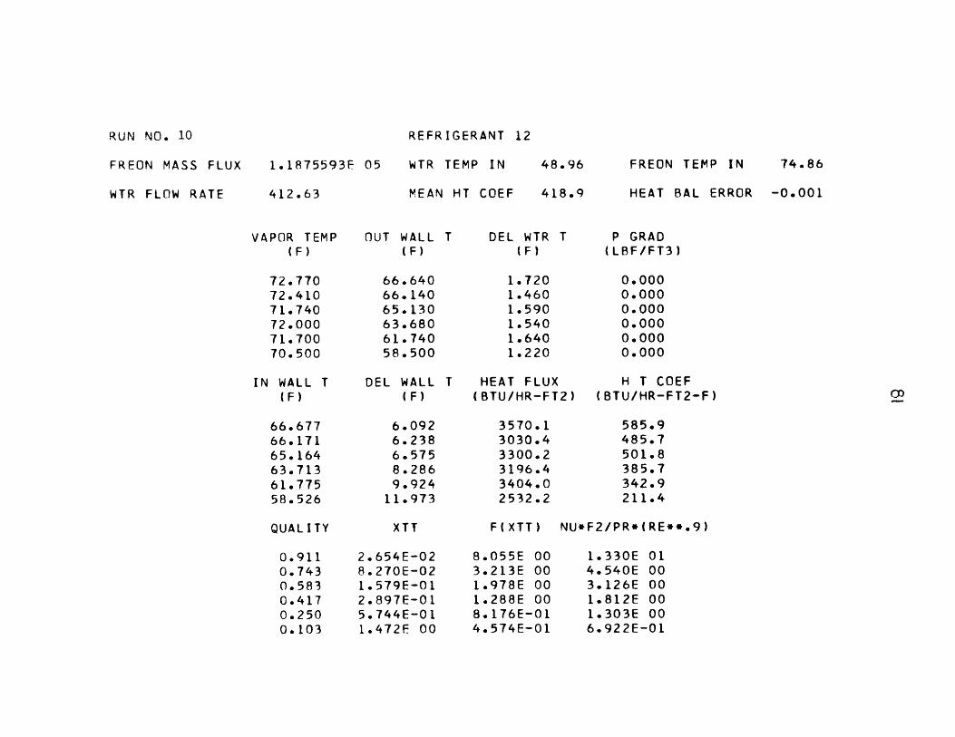
RUN NO. 10
FREON MASS FLUX
WTR FLOW RATE
1.1875593F 05
412.63
REFRIGERANT 12
WTR TEMP IN 48.96
MEAN HT COEF 418.9
FREON TEMP IN 74.86
HEAT BAL ERROR -0.001
VAPOR TEMP(F)
72.77072.41071.74072.00071.70070.500
IN WALL T(F)
66.67766.17165.16463.71361.77558.526
OUT WALL(F)
66.64066.14065.13063.68061.74058.500
DEL WALL(F)
6.0926.2386.5758.2869.924
11.973
T DEL WTR T(F)
1.7201.4601.5901.5401.6401.220
P GRAD(LBF/FT3)
0.0000.0000.0000.0000.0000.000
HEAT FLUX H T COEF(BTU/HR-FT2) (BTU/HR-FT2-F)
3570.13030.43300.23196.43404.02532.2
585.9485.7501.8385.7342.9211.4
F(XTT) NU*F2/PR*(RE**.9)
2.654E-028. 270E-021.579E-012.897E-015.744E-011.472F 00
8.055E 003.213E 001.978E 001.288E 008. 176E-014.574E-01
1.330E 014.540E 003.126E 001.812E 001.303E 006.922E-01
QUALITY XTT
0.9110.7430.5830.4170.2500.103

REFRIGERANT 12
FREON MASS FLUX
WTR FLOW RATE
2.8129662E
696.57
WTR TEMP IN 75.52
MEAN HT COEF 475.3
FREON TEMP IN
HEAT BAL ERROR
VAPOR TEMP(F)
107.380107.210107.120106.830106.000105.000
IN WALL T(F)
97.50896.03895.00093.13190.03588.029
OUT WALL(F)
97.43095.96095.00093.05089.96087.960
DEL WALL(F)
9.87111.17112.11913.69815.96416.970
T DEL WTR(F)
2.1602.1400.0002.2202.0601.910
HEAT FLUX(BTU/HR-FT
7568.47498.3
0.07778.77218.06692.4
T P GRAD(LBF/FT3)
29.16024.49423.32717.49512.2475.831
H T COEF2) (BTU/HR-FT2-F)
766.7671.1
0.0567.8452.1394.3
F(XTT) NU*F2/PR*(RE**.9)
3.600E-021.173E-011.706E-012.404E-014.556E-019.282E-01
6.246E 002.463E 001.870E 001.466E 009.506E-016.045E-01
8.111E 002.835E 000.OOOE 001.556E 009. 396E-016.759E-01
107.42
0.003
QUAL I TY XTT
0.9090.7300.6400.5480.3720.210
RUN NO. 11
REFRIGERANT 12
FREON MASS FLUX
WTR FLOW RATE
6.6783725F 05
1172.11
WTR TEMP IN 36.96
MEAN HT COEF 1804.1
FREON TEMP IN
HEAT BAL ERROR
VAPOR TEMP(F)
80.52078.57076.87075.48073.35071.260
IN WALL T(F)
73.04972.98267.26065.28462.01859.732
OUT WALL(F)
72.86072.82067.09065.13061.87059.590
DEL WALL(F)
7.4705.5879.609
10.19511.33111.527
T DEL WTR T(F)
3.0802.6502.7802.5102.4102.320
T HEAT FLUX(-BTU/HR-FT2)
18159.615624.416390.814798.914209.313678.7
P GRAD(LBF/FT3)
228.031222.199191.872150.174120.13973.774
H T COEF(BTU/HR-FT2-F)
2430.72796.41705.71451.41253.91186.6
F(XTT) NU*F2/PR*(RE**.9)
2.712E-028.001E-021.455F-012.392E-013.743E-016. 186E-01
7.910E 003.297E 002.100E 001.471E 001.083E 007.797E-01
1.356E 016.519E 002.667E 001.745E 001.256E 001.031E 00
81.00
0.025
QUALITY XTT
0.9160.7630.6190.4800.3530.234
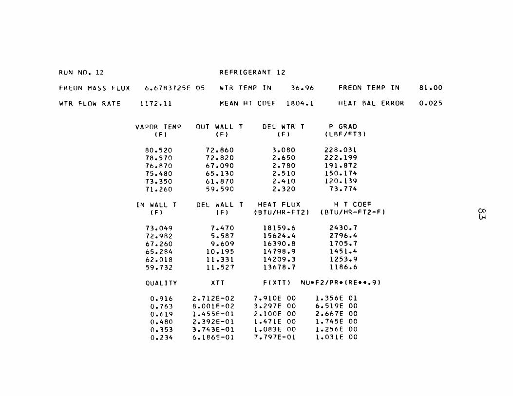
RUN NO. 12

RUN NO. 13
FREON MASS FLUX
WTR FLOW RATE
7.6344000E 05
890.98
VAPOR TEMP(F)
91.70090.22087.96087.70085.70083.860
REFRIGERANT 12
WTR TEMP IN 47.41
MEAN HT COEF 1989.7
OUT WALL T DEL WTR T(F) (F)
85.78085.43080.61078.87075.57073.350
3.4103.0803.2503.0203.1603.040
FREON TEMP IN
HEAT BAL ERROR
P GRAD(LBF/FT3)
226.213.174.161.128.89.
864742376254887521
T DEL
85.93985.57380.76179.01175.71773.491
QUALITY
5.4.7.8.9.
10.
WALL(F)
760646198688982368
XTT
HEAT FLUX(BTU/HR-FT2)
15283.213804.114566.113535.214162.713624.9
H T COEF(BTU/HR-FT2-F)
2652.92971.02023.51557.71418.71314.1
F(XTT) NU*F2/PR*(RE**.9)
2. 175E-026.481E-021.130E-011.789E-012.616E-013.848E-01
9.537E3.886E2.533E1.808E1.382E1.063E
1.724E 017.733E 003.490E 002.028E 001.514E 001.196E 00
94.48
0.039
IN WALL(F)
0.9390.8200.7060.5900.4810.372
REFRIGERANT 12
FREON MASS FLUX
WTR FLOW RATE
9.0910312E 05
996.25
WTR TEMP IN 72.05
MEAN HT COEF 1969.4
FREON TEMP IN
HEAT BAL ERROR
VAPOR TEMP(F)
109.710108.830106.870106.830105.170103.430
IN WALL T(F)
103.555103.75998.73097.54594.73392.204
OUT WALL(F)
103.390103.61098.57097.39094.57092.040
DEL WALL(F)
6.1545.0708.1399.284
10.43611.225
T DEL WTR T(F)
3.1602.8703.0702.9703.1403.150
T HEAT FLUX(BTU/HR-FT2)
15835.914382.615384.914883.815735.715785.8
P GRAD(LBF/FT3)
203.536212.867172.044166.503134.71996.227
H T COEF(BTU/HR-FT2-F)
2572.82836.71890.11603.01507.81406.2
F(XTT) NU*F2/PR*(RE**.9)
2.258E-026.765E-021.171E-011.854E-012.714E-013.985E-01
9.237E 003.757E 002.466E 001.762E 001.347E 001.038E 00
1.539E 016.716E 002.952E 001.872E 001.429E 001.125E 00
112.48
0.046
QUALITY XTT
0.9440.8340.7280.6160.5080.398
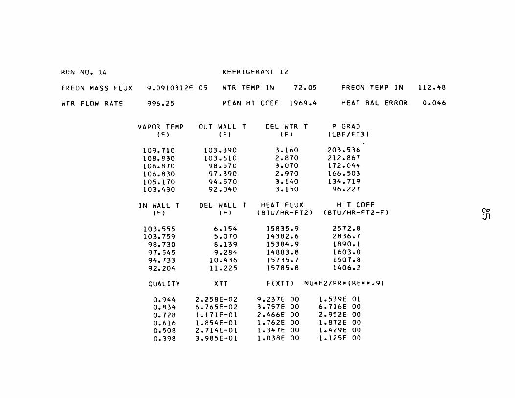
RUN NO. 14

REFRIGERANT 12
FREON MASS FLUX
WTR FLOW RATE
9.1649862E 05
1810.95
WTR TEMP IN 108.96
MEAN HT COEF 1369.0
FREON TEMP IN 140.38
HEAT BAL ERROR -0.028
VAPOR TEMP(F)
138.250138.040136.710137.500136.250135.080
IN WALL T(F)
130.145128.176123.749123.541121.576119.607
OUT WALL(F)
129.960128.000123.580123.380121.420119.460
DEL WALL(F)
8.1049.863
12.96013.95814.67315.472
T DEL WTR T(F)
1.9501.8601.7901.7001.6501.550
P GRAD(LBF/FT3)
160.380123.05592.72880.19056.86131.784
HEAT FLUX H T COEF(BTU/HR-FT2) (BTU/HR-FT2-F)
17763.516943.716306.015486.215030.714119.7
2191.61717.81258.11109.41024.3912.5
F(XTT) NU*F2/PR*(RE**.9)
3.464E-021.090E-011.973E-013.242E-014.954E-017.690E-01
6.448E 002.603E 001.685E 001.193E 008.999E-016.794E-01
1.055E 013.241E 001.575E 001.054E 008.052E-016. 190E-01
QUALITY
co
XTT
0.9310.7900.6590.5280.4090.297
RUN NO. 15

REFRIGERANT 12
FREON MASS FLUX
WTR FLOW RATE
1.1296822E
1843.07
06 WTR TEMP IN 95.91
MEAN HT COEF 2011.8
FREON TEMP IN
HEAT BAL ERROR
VAPOR TEMP(F)
122.670121.710120.080118.910117.500115.880
IN WALL T(F)
116.316114.464111.879109.872108.328106.582
OUT WALL(F)
116.130114.290111.710109.710108.170106.430
DEL WALL(F)
353245200037171297
T DEL WTR T(F)
1.9261.8041.7571.6871.6391.583
T HEAT FLUX(BTU/HR-FT2)
17856.116725.016289.315640.315195.314676.1
P GRAD(LBF/FT3)
274.687233.280193.62296.227
157.463122.472
H T COEF(BTU/HR-FT2-F)
2810.22308.21986.41730.61656.71578.5
XTT
2.420E-027. 199E-021.230E-011.834E-012.556E-013.449E-01
F(XTT) NU*F2/PR*(RE**.9)
8.710E3.579E2.377E1.775E1.405E1 * 144E
000000000000
1.433E4.665E2.670E1.783E1.407E1 . 155E
010000000000
124.62
-0.059
QUALITY
0.9470.8400.7410.6460.5550.468
RUN NO. 16

REFRIGERANT 22
FREON MASS FLUX
WTR FLOW RATE
2.5736990F 05
1250.82
WTR TEMP IN 80.35
MEAN HT COEF 754.0
FREON TEMP IN 96.88
HEAT SAL ERROR -0.065
VAPOR TEMP(F)
95.48095.96095.43096.12095.30093.910
IN WALL T(F)
89.84289.66788.22787.79986.74885.751
CUT WALL(F)
89.78089.61088.17087.74086.70085.700
DEL WALL(F)
5.6376.2927.2028.3208.5518.158
T DEL WTR T(F)
0.9500.8700.8700.9100.7400.780
T HEAT FLUX(BTU/HR-FT2)
5977.35473.95473.95725.64656.04907.7
P GRAD(LBF/FT3)
20.41126.24320.41120.41114.58010.205
H T COEF(BTU/HR-FT2-F)
1060.2869.8759.9688.1544.4601.5
F(XTT) NU*F2/PR*(RE**.9)
2.373E-027.080E-021.232E-011.942F-012.771E-013.774E-01
8.855E 003.626E 002.375E 001.704E 001.328E 001.077E 00
1.414E 014.678E 002.715E 001.852E 001.206E 001.154E 00
QUALITY XTT
0.9430.8320.7280.6180.5200.432
RUN NO. 17

REFRIGERANT 22
FREON MASS FLUX
WTR FLOW RATE
2.4756590E 05
1089.37
WTR TEMP IN 60.77
MEAN HT COEF 764.8
FREON TEMP IN
HEAT BAL ERROR
VAPOR TEMP(F)
83.27084.09083.23084.17082.91084.130
IN WALL T(F)
76.69376.20573.82273.02771.03369.417
OUT WALL(F)
76.61076.13073.74072.96070.96069.350
DEL WALL(F)
6.5767.8849.407
11.14211.87614.712
T DEL WTR T(F)
1.4601.3201.4501.1801.2801.180
T HEAT FLUX(BTU/HR-FT2)
8000.57233.37945.76466.27014.16466.2
P GRAD(LRF/FT3)
24.20224.20220.99517.20412.2477.581
H T COEF(BTU/HR-FT2-F)
1216.5917.4844.6580.3590.5439.5
F(XTT) NU*F2/PR*(RE**.9)
2. 844E-028.870E-021.660E-012.810E-014.432E-017.994E-01
7.601E 003.045E 001.907E 001.315E 009.680E-016.631E-01
1.291E 013.944E 002.385E 001.249E 001.053E 006.684E-01
85.09
0.025
QUAL I TY XTT
0.9240.7770.6320.4920.3650.232
RUN NO. 18

REFRIGERANT 22
FRECN MASS FLUX
WTR FLOW RATE
2.5346834F 05
879.57
WTR TEMP IN 78.43
MEAN HT COEF 820.4
FREON TEMP IN
HEAT BAL ERROR
VAPOR TEMP(F)
98.70099.26098.59099.30098.26097.780
IN WALL T(F)
93.49593.28091.28690.48988.80487.152
OUT WALL(F)
93.43093.22091.22090.43088.74087.090
DEL WALL(F)
5.2045.9797.3038.8109.455
10.627
T DEL WTR T(F)
1.4301.3101.4401.3001.3901.350
T HEAT FLUX(RTU/HR-FT2)
6326.95796.06371.25751.86150.05973.0
P GRAD(LBF/FT3)
24.20219.82815.74614.58014.5809.331
H T COEF(BTU/HR-FT2-F)
1215.7969.2872.3652.8650.3562.0
F(XTT) NU*F2/PR*(RE**.9)
2.672F-027.995E-021.440F-012.329E-013.508E-015.454E-01
8.009E 003.299E 002.116E 001.499E 001.131E 008.454E-01
1.520E 014.922E 002.901E 001.635E 001.328E 009.702E-01
100.04
0.045
QUALITY XTT
0.9370.8170.6970.5760.4610.343
RUN NO. 19

RUN NO. 20
FREON MASS FLUX
WTR FLOW RATE
2.2254859E 05
558.51
REFRIGERANT 22
WTR TEMP IN
MEAN HT COEF
98.35
614.3
FREON TEMP IN
HEAT BAL ERROR
VAPOR TEMP(F)
116.610117.210116.830117.420116.740116.260
Ti WALI
(F)
112.534112.385111.616110.298108.872107.581
OUT WALL(F)
112.500112.350111.580110.260108.830107.540
T DEL WALL(F)
4.0754.8245.2137.1217.8678.678
T DEL WTR T(F)
.170.220.260.300.440.430
HEAT FLUX(BTU/HR-FT2)
3287.03427.53539.93652.24045.64017.5
P GRAD(LBF/FT3)
11.95513.12111.95510.2058.7476.123
H T COEF(BTU/HR-FT2-F)
806.4710.4679.0512.8514.1462.9
XTT
2.003E-026.027E-021.058E-011.629E-012.351E-013.341F-01
F(XTT) NU*F2/PR*(RE**.9)
1.023E4. 116E2.662E1.934E1.489E1. 169E
010000000000
1.718E5.862E3.588E2.004E1.593E1 . 186E
118.26
-0.056
QUALITY
0.9600.8790.7940.7060.6140.518

REFRIGERANT 22
FREON MASS FLUX
WTR FLOW RATE
1.3886631F 05
589.97
WTR TEMP IN 75.17
MEAN HT COEF 533.6
FREON TEMP IN 93.43
HEAT BAL ERROR -0.064
VAPOR TEMP(F)
93.26093.70093.22093.57092.70092.390
IN WALL T(F)
88.93288.77087.33486.46584.99583.714
OUT WALL(F)
88.90088.74087.30086.43084.96083.680
DEL WALL(F)
4.3274.9295.8857.1047.7048.675
T DEL WTR T(F)
1.0501.0001.1301.1501.1501.130
P GRAD(LBF/FT3)
8.1648.1646.7066.4154.9573.790
HEAT FLUX H T COEF(BTU/HR-FT2) (BTU/HR-FT2-F)
3116.02967.63353.43412.83412.83353.4
720.0602.0569.8480.3442.9386.5
F(XTT) NU*F2/PR*(RE**.9)
2.275E-026.779E-021.225E-012.008F-013.076E-014.759E-01
9.179E 003.751E 002.384E 001.664E 001.236E 009.238E-01
1.637E 015.527E 003.382E 002.101E 001.552E 001.136E 00
QUALITY XTT
0.9440.8360.7250.6050.4860.367
RUN NO. 21

REFRIGERANT 22
FREON MASS FLUX
WTR FLOW RATF
1.4703040F 05
485.72
WTR TEMP IN 74.46
MEAN HT COEF 568.2
FREON TEMP IN 93.22
HEAT BAL ERROR -0.070
VAPOR TEMP(F)
92.26092.57092.26092.70092.09091.870
IN WALL T(F)
88.92888.63587.41886.81085.73184.602
OUT WALL(F)
88.90088.61087.39086.78085.70084.570
DEL WALL(F)
3.3313.9344.8415.8896.3587.267
T DEL WTR T(F)
1.1301.0201.1201.1801.2201.260
T HEAT FLUX(BTU/HR-FT2)
2760.92492.12736.42883.02980.83078.5
P GRAD(LBF/FT3)
8.1649.3319.3318.1648.1646.706
H T COEF(BTU/HR-FT2-F)
828.7633.4565.2489.4468.7423.5
F(XTT) NU*F2/PR*(RE**.9)
1.878E-025.420E-029. 337E-021.451E-012. 107E-013.029E-01
1.081E 014.479E 002.927E 002.105E 001.609E 001.249E 00
2.108E 016.562E 003.845E 002.470E 001.887E 001.418E 00
CUALITY XTT
0.9540.8660.7800.6850.5890.488
RUN NO. 22

RUN NO. 23
FREON MASS FLUX
WTR FLOW RATE
1.5033075E 05
544.99
REFRIGERANT 22
WTR TEMP IN
MEAN HT COEF
49.68
507.8
FREON TEMP IN 82.87
HEAT BAL ERROR -0.028
VAPOR TEMP(F)
78.87079.55078.83079.41078.13076.170
IN WALL T(F)
72.04671.87069.57768.46865.66861.879
OUT WALL(F)
72.00071.83069.52068.41065.61061.830
DEL WALL(F)
6.8237.6799.252
10.94112.46114.290
T DEL WTR T(F)
1.6401.4102.0002.0402.0501.720
P GRAD(L8F/FT3)
0.0000.0000.0000.0000.0000.000
HEAT FLUX H T COEF(BTU/HR-FT2) (BTU/HR-FT2-F)
4495.93865.45482.85592.55619.94715.2
658.9503.3592.5511.1450.9329.9
F(XTT) NU*F2/PR*(RE**.9)
2.444E-027.460E-021.450E-012.782E-015.275E-011.146E 00
8.637E 003.481E 002.105E 001.324E 008.639E-015.314E-01
1.158E 013.599E 002.678E 001.639E 001.136E 007.004E-01
QUALITY XTT
0.9320.8010.6560.4820.3110.157

REFRIGERANT 22
FREON MASS FLUX
WTR FLOW RATE
7.3864387E
1508.44
WTR TEMP IN 36.57
MEAN HT COEF 2062.5
FREON TEMP IN
HEAT BAL ERROR
VAPOR TEMP(F)
79.05079.05077.46077.82076.09074.640
OUT WALL(F)
T DEL WTR(F)
71.22072.05067.41065.43062.41055.320
3.1902.6202.8502.5002.7702.360
T P GRAD(LBF/FT3)
183.707189.540148.716134.135119.55543.740
IN WALL T DEL WALL T HEAT FLUX(F) (F) (BTU/HR-FT2)
71.472 7.577 24205.172.257 6.792 19880.067.635 9.824 21625.265.627 12.192 18969.562.628 13.461 21018.255.506 19.133 17907.2
XTT
714E-02119E-02434E-01334E-01575F-01652E-01
H T COEF(BTU/HR-FT2-F)
3194.22926.62201.11555.81561.4935.9
F(XTT) NU*F2/PR*(RE**.9)
7.904E 003.259E 002.123E 001.496E 001.117E 008.262E-01
1.362E 015.154E 002.605E 001.408E 001.162E 005.975E-01
81.83
0.028
QUALITY
0.9250.7850.6560.5270.4050.287
RUN NO. 24

REFRIGERANT 22
FREON MASS FLUX
WTR FLOW RATE
5.9624675E 05
1491.60
WTR TEMP IN 53.05
MEAN HT COEF 1422.4
FREON TEMP IN
HEAT BAL ERROR
VAPOR TEMP(F)
93.91094.48093.17094.17092.48091.000
IN WALL(F)
84.30684.77279.85278.01273.88170.710
OUT WALL(F)
84.09084.57079.64077.82073.70070.550
T DEL WALL(F)
9.6039.707
13.31716.15718.59820.289
T DEL WTR T(F)
2.7702.5902.7202.4602.3202.050
T HEAT FLUX(BTU/HR-FT2)
20783.619433.020408.518457.617407.215381.4
P GRAD(LBF/FT3)
110.80799.14372.90055.40334.99121.870
H T COEF(BTU/HR-FT2-F)
2164.12001.81532.41142.3935.9758.0
F(XTT) NU*F2/PR*(RE**.9)
3.444E-021.110E-012. 143E-013.902E-016.808E-011.361E 00
6.479E 002.568E 001.589E 001.053F 007.336E-014.791E-01
1.021E 013.764E 001.889E 001.064E 007.217E-015.074E-01
96.42
0.029
QUALITY XTT
0.9150.7480.5860.4230.2800.151
RUN NO. 25

RUN N'JO. 26
FREON MASS FLUX
WTR FLOW RATE
5.8922237E
1569.60
REFRIGERANT 22
WTR TEMP IN 36.33
MEAN HT COEF 1384.4
FREON TEMP IN
HEAT BAL ERROR
VAPOR TEMP(F)
85.78086.70085.00086.52084.09081.520
IN WALL T(F)
75.01274.78268.57066.11960.05154.285
OUT WALL(F)
74.73074.55068.32065.87059.86054.140
DEL WALL(F)
10.76711.91716.42920.40024.03827.234
T DEL WTR(F)
3.4302.8303.0503.0302.3301.770
HEAT FLUX(BTU/HR-FT2)
27081.522344.224081.223923.318396.413975.0
P GRAD(LRF/FT3)
77.27494.77064.15242.28124.78511.663
H T COEF(BTU/HR-FT2-F)
2515.01874.91465.71172.6765.2513.1
F(XTT) NU*F2/PR*(RE**.9)
4. 135E-021.360E-012.709E-015.851E-011.388E 008.808E 00
.574E 00
.206E 00
.349E 00
.080E-01
.737F-01.687E-01
9.624E 002.951E 001.551E 009.344E-015.087E-013.045E-01
89.04
0.063
QUALITY XTT
0.8920.6890.5040.3040.1400.020

REFRIGERANT 22
FREON MASS FLUX
WTR FLOW RATE
6.8991512E 05
1153.34
WTR TEMP IN 82.91
MEAN HT COEF 1726.8
FREON TEMP IN
HEAT BAL ERROR
VAPOR TEMP(F)
111.460111.680110.740111.230109.830109.120
IN WALL T(F)
106.301105.915103.176102.044100.14298.362
OUT WALL(F)
106.170105.790103.040101.910100.00098.220
DEL WALL(F)
5.1585.7647.5639.1859.687
10.757
T DEL WTR T(F)
2.1802.0802.2602.2202.3502.360
T HEAT FLUX(BTU/HR-FT2)
12647.512067.313111.612879.613633.813691.8
P GRAD(LBF/FT3)
108.475102.64386.89679.31567.65148.988
H T COEF(BTU/HR-FT2-F)
2451.92093.41733.51402.11407.21272.7
F(XTT) NU*F2/PR*(RE**.9)
2.324E-026.850E-021. 197E-011.871E-012.691E-013.868E-01
9.014E 003.721F 002.426E 001.750E 001.355E 001.059E 00
1.692E 015.742E 003.081E 001.851E 001.494E 001.129E 00
113.04
0.031
QUALITY XT T
0.9520.8570.7620.6620.5640.462
RUN NO. 27

99
APPENDIX 2
LIST OF RELEVANT VARIABLES FOR THEORETICAL PROGRAM
TSAT refrigerant temperature entering test section
DET difference between vapor temperature and inside wall temperature
G refrigerant flow rate
E ratio of eddy conductivity to eddy viscosity
GR gravitational constant
A axial acceleration due to external forces
DDXDZ D(dx/dz)
UL,UV liquid and vapor viscosities
KL liquid thermal conductivity
CL liquid specific heat
ROL,ROV liquid and vapor densities
RU ratio of liquid to vapor viscosities
RRO ratio of vapor to liquid densities
PR Prandtl number
X: 1 minus quality
X quality
DPF frictional pressure gradient
V void fraction
DPG gravitational pressure gradient
RE Reynolds number
DPM momentum pressure gradient
DPT total pressure gradient
DP delta plus
TAO wall shear stress

BT
FO F0
M M
MUSED indicator showing if M term was used in the calculation of F2
F2 F2
K indicator showing number of iterations to obtain correctD(dx/dz)
YDIS right term of Eq. (31)
HZ local heat transfer coefficient
L total length of condensation
DDD new value of D(dz/dz) for iteration
HM mean heat transfer coefficient

PAGE 1 TRAVISS
// JCE T 1130 1131 1131 1131 TRAVISS
LCG DRIVF CART SPEC CART AVAIL PFY ORIVE00CC 1130 1130 CCC0001 1131 1131 OCOC
V2 fC9 ACTUAL 8K CONFIG PK
// FCR*IGCS (CARC,1403 PRINTER)* LIST SCURCE PROGRAV
REAL L,MKLCIVENSICN SF(19)CATA C/.0265/REAC (2,1C) N
IC FCR'AT (16)CC 21 1=1,NREAC (2,11) TSATCETC,E
i FCRVAT (4F8.0)GR=4.17E8
C GRAVITY FCRCEA=0.0
C CUALITY GRACIENTCCXCZ=-.OCL
C PHYSICAL PRCPERTIESUL=0.673-(0.0C135*TSAT)UV=C.C28+((0.5*TSAT)/lCOOC.)KL=0.C699-((0.235*TSAT)/lCC.)RCL=86.056-(.149*TSAT)IF(TSAT-100) 5,5,6
5 RCV=(.05*TSAT)-1.1115FFG=98.363-(0.255*TSAT)CL=.255+.6*TSAT/1CCO.GC TC 7
6 RCV=.0665*TSAT-2.6593
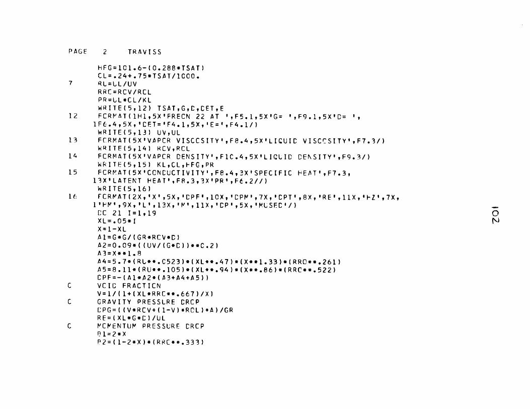
PAGE 2 TRAVISS
HFG=1C1.6-( 0.288*TSAT)CL= .24+. 75*TSAT/1000.
7 RL=LL/UVRRC=RCV/RCLPR=LL*CL/KLWRITE(5, 12) TSATGCCET,E
12 FCRV'AT(lH1,5X'FRECN 22 AT ',F5.1,5X'G= ',F9.1FL.4,5X, 'CET='F4.1,5X,'E=',F4.1/)WRITE(5,13) UV,UL
13 FCRMAT(5X'VAPCR VISCCSITY',Fe.4,5X'LIQUIC VIWRITE(5,14) RCVRCL
14 FCRMAT(5X'VAPCR DENSITY'gF1C.4,5X'LIQLID CENWRITI±(5, 15) KLCLq-FGqPR
15 FCRPAT(5X'CCNEUCTIVITY' ,F8.4,'X'SPECIFIC IHEA13XILATENT H-EAT'FF.3,3X'PR' ,F6.2//)
ifFCRPAT(2X, 'X' ,5X, 'CPF' ,1CX, CPM' ,7X, 'CPT' ,8X1II"' , 9X,'L' , 13X, p' lviX, CP , 5X, 'USEC '1)CiC 21 I1, 919X L .05 *IX=1 -XLA 1=G*G/ (GR*RCV*C)42=O.09*((UV/(G*C))**C.2)A 3 =X **1 . 8t4=5.7*(RL**.C523)*(XL**.47)*(X**1.33)*(RRC*A5=8.*11* (RU**.105)*( XL** .94) *(X**.86 ) *(RRC**CPF=-(AI*A2*(A3+A4+A5))
C VCIC FRACTICNV=1/(l+(XL*RRC**.667)/X)
C GRAVITY PRESSURE CRCP[.'PG= ((V*RCV+ (1-V) *RCL )*A )/GRRE= (XL*G*C )/UL
C V'CPENTUJM PRESSURE CRCP131=2*XP2=(1-2*X)*(RRC**.333)
1,5X'C= ',9
SCCSITY' ,F7.3/)
SITY' ,Fg.3/)
T 9F7 .39
9'RE'?I1X,'I-Z',7X,
*.,2 61).522)

PAGF 3 TRAVISS
C3=(1-2*X)*(RRC**.667)P4=2*XL*RR -
1 CPV=-(Al*CCXCZ*(E1+B2+B3+B4))C TCTAL PRESSURE DRCP
CPT=CPF+CPV+CPGC CELTA PLUS
IF(RE-5C.) 30,30,313C CP=.7C71*RF**.5
GC TC 3631 IF(RE-1125.) 32,32,3332 CP=.48l8*RE**.585
GC TC 363 1 CP=.095*RE**.81236 TAC=-(CPF*D/4.)C CALCULATE BETA
IF(CP-90.) 37,37,3837 PT=2.368-.259*ALCG(CP)
CC TC 3938 P1=1.2C CALCULATE FC393 Gl=RRC**.333/(1.-V)
G2=(XL*(2.-eT)*RRC)/((1.-V)*(1.-V))FC=-CPT+(A/GR)*RCL-(Al*CCXCZ*(Gl-G2))
C CALCULATE F2V=(FC*CP*LL)/(TAC*SCRT(GR*TAC*RCL))
'LSEC=CIF(CP-5.) 40,4C,41
4C F2=DP*PRK=C
4142
GC TC 44IF(CP-30) 42,42,43F2=5.*PR+5.*ALCG(1.+E*PR*(CP/5.-1.))/EK=GC TC 44
43 Yl=((1+PR)**.l*(2.71828**(.1*PR)))/3C.YCIS=(Yl*(CP**1.05)-CP)/((Yl*(DP**1.05))-2.5*Yl*(CP**.05)/PR-3C

PAGF 4 TRAVISS
1+2.5/PR)-PIF(YCIS) 60,6C,61
6C C1=SCRT(1.+lC.*M/(PR*CP*E))C2=6C.*P/CP-1.-C1C3=60.*N/CP-1.+C1C4=2.*F-1.+C1
Cr5=2. *fP-1 .-C 1F2=5.*PR+5.*ALCG(1.+5.*E*PR)/E+(2.PLSEC=1
GC TC 6261 F2=5*PR+5*(ALCG(l+5*PR*E))/E+2.5*(62 K=1C LCCAL HEAT TRANSFER CCEFFICIENT44 FZ=CL*SQRT(GR*TAC*RGL)/F2
L=.05*HFG*G*C/(4.*FZ*CFT)IF(K) 3,3,4
4 CCC=.C25*C/LC NEW QLALITY GRADIENT
S=ABS((CCC+CDXCZ)/DCXCZ)-.01IF(S) 3,3,2
2 ccXCZ=-CCCWRITE(5,50) CCC
5C FCRVAT (1CX,E14.8)GC TC 1
C PEAN HEAT TRANSFER CCEFFICIENT3 IF(I-1) 19,19,2019 HV=FZ
SF(I )=1/HZGC TC 23
2C IR=I-1RH= 1/HZSH(I)=RH+SH(IR)E-P= I/SH(I
23 WRITE(5,17) X,CPFCPFCPT,REF Z,M17 FCRPAT(F4.2,F9.3,E14.3,F9.3,E14.5,
5*ALCG((C4*C2)/(C5*C3)))/(Cl*E)
ALCG(CP/3C))
,L,0 ,CPtLSEC2F9.1,2E14.5,F9.3,I6)
PAGE 5 TRAVISS
21 CCNTINUEENC
O