Embed Size (px)
Citation preview

Phone: 800-494-6656 www.ButlerTechnologies.com Page 1 of 10
Force Sensing Resistor Technical Guidelines Rev 0 (02-24-14) by M. Wagner
The Force-Sensing-Resistor (FSR) is made of a proprietary carbon-based piezoresistive ink, typically screen printed
on polyester film (PET). As force is applied to the FSR, the electrical resistance decreases. The FSR carbon ink
formulation can be customized for application-specific requirements. There are two basic FSR configurations: the
ShuntModeTM and the ThruModeTM. The details of each will be explained later on in this document. The main
purpose of a pressure sensor (tactile force sensor), such as an FSR, is to measure the forces applied to a specific area
and then relay that information via selected output or electronics.
The diagrams below illustrate the relationship between the applied Pressure (Load) and the resulting Resistance of a
Force Sensing Resistor. Diagram 1 depicts the change in resistance as the pressure load is applied and then released.
As the pressure load is increased, the resistance decreases. When the load is removed, the sensor’s resistance
returns to its normal state. Diagram 2 illustrates how carbon-based FSR ink particles become compressed under
increasing loads, resulting in the conductive particles being closer in proximity to one another allowing for a shorter
conductive path leading to a lower overall resistance.
Diagram 1 Diagram 2

Phone: 800-494-6656 www.ButlerTechnologies.com Page 2 of 10
Force Sensing Resistor Characteristics
PROPERTY VALUE NOTES
Size Range Limited only by printing equipment Any shape, compound curves
Force Sensitivity Range 1 oz. to 20 lbs. Mechanical interface dependent
Pressure Sensitivity Range 1 psi to 125 psi Mechanical interface dependent
Part-to-Part Repeatability Approx. +/-20% of average resistance With consistent actuation
Maximum Current 0.5mA Keep the current low. Overheating will destroy
the FSR device.
Single Part Force Repeatability +/-5% of established resistance With consistent actuation
Force Resolution 1% full scale
Stand-off Resistance 100K Ohms to 1M Ohms No load, formula dependent
Switch Travel Zero to Thickness of Spacer
Devise Rise Time 1 msec
Lifecycle 1,000,000+ Actuations
Temperature Range -15°F to +200°F Substrate specification limitations
Device Thickness Substrate and Spacer Dependent
Force Sensing Carbon Ink can be custom blended for specific applications

Phone: 800-494-6656 www.ButlerTechnologies.com Page 3 of 10
ShuntModeTM FSR
A ShuntModeTM FSR is comprised of conductive silver interdigitated fingers on the bottom PET film layer shorted by
the FSR element on the top PET film layer. The ShuntModeTM FSR has a more dynamic range, would not saturate as
quickly, and have a larger actuation force versus a comparable ThruModeTM FSR. These are good for high-volume
applications since it uses less silver ink than the ThruModeTM FSR and thus lower cost. NOTE: these sensors can be
manufactured in other geometries such as rectangular. The tails can be terminated with 2.54mm pitch female
connectors (latching or non-latching), a 1mm pitch ZIF-style connection, or 2.54mm pitch male solder tabs.
Top Circuit with printed FSR Carbon Ink:
Typically 0.005” thick clear Polyester
Spacer Layer:
Typically 0.002” to 0.005” thick Spacer Adhesive
Bottom Circuit with printed Conductive
Silver Traces and Dielectric Tail Insulation:
Typically 0.005” thick clear Polyester
Rear/Bottom Pressure Sensitive Adhesive:
Typically 0.002” to 0.005” thick PSA

Phone: 800-494-6656 www.ButlerTechnologies.com Page 4 of 10
ThruModeTM FSR
A ThruModeTM FSR is comprised of conductive silver electrodes overprinted with proprietary FSR carbon ink
technology on both the top and bottom circuit layers. The Thru ModeTM FSR would saturate with a smaller force but
also be more response to smaller forces versus a comparable ShuntModeTM FSR. The ThruModeTM FSR requires more
carbon FSR ink and thus more costly. Very small size applications can benefit from a ThruModeTM device because this
configuration does not use interdigitated fingers which have a print size limitation. NOTE: these sensors can be
manufactured in other geometries such as rectangular. The tails can be terminated with 2.54mm pitch female
connectors (latching or non-latching), a 1mm pitch ZIF-style connection, or 2.54mm pitch male solder tabs.
Top Circuit with printed Conductive Silver,
FSR Carbon Ink, and Dielectric Tail Insulation:
Typically 0.005” thick clear Polyester
Spacer Layer:
Typically 0.002” to 0.005” thick Spacer Adhesive
Bottom Circuit with printed Conductive Silver,
FSR Carbon Ink, and Dielectric Tail Insulation:
Typically 0.005” thick clear Polyester
Rear/Bottom Pressure Sensitive Adhesive:
Typically 0.002” to 0.005” thick PSA

Phone: 800-494-6656 www.ButlerTechnologies.com Page 5 of 10
ShuntModeTM Matrix Array FSR
A ShuntModeTM Matrix Array is used where measurements of multiple inputs of force and locations are needed
simultaneously. It operates in the same manner as the single ShuntModeTM FSR shown above but constructed in a
matrix of multiple sensors. The tails can be terminated with 2.54mm pitch female connectors (latching or non-
latching), a 1mm pitch ZIF-style connection, or 2.54mm pitch male solder tabs.
Top Circuit with printed FSR Carbon Ink:
Typically 0.005” thick clear Polyester
Spacer Layer:
Typically 0.002” to 0.005” thick
Spacer Adhesive
Printed Dielectric #2
Printed Conductive Silver Jumpers
Printed Dielectric #1
Bottom Circuit with printed
Conductive Silver Traces:
Typically 0.005” thick clear Polyester
Rear/Bottom Pressure Sensitive Adhesive:
Typically 0.002” to 0.005” thick PSA

Phone: 800-494-6656 www.ButlerTechnologies.com Page 6 of 10
ThruModeTM Matrix Array FSR
A ThruModeTM Matrix Array is able to measure multiple position and force inputs. The Matrix array can be used in a
variety of innovative musical, human input, and touch-sensing designs. It operates in the same manner as the single
ThruModeTM FSR shown above but constructed in a matrix of multiple long, rectangular sensors. The tails can be
terminated with 2.54mm pitch female connectors (latching or non-latching), a 1mm pitch ZIF-style connection, or
2.54mm pitch male solder tabs.
Top Circuit with printed Conductive Silver,
FSR Carbon Ink, and Dielectric Insulation:
Typically 0.005” thick clear Polyester
Spacer Layer:
Typically 0.002” to 0.005” thick
Spacer Adhesive
Bottom Circuit with printed Conductive Silver, FSR
Carbon Ink, and Dielectric Insulation/Standoffs:
Typically 0.005” thick clear Polyester
Rear/Bottom Pressure Sensitive Adhesive:
Typically 0.002” to 0.005” thick PSA

Phone: 800-494-6656 www.ButlerTechnologies.com Page 7 of 10
Effect of the Spacer’s Thickness and Inside Diameter on Activation Force
As with a typical membrane switch, the top and bottom circuit layers can be spaced apart using various thicknesses
of spacer material such as 3M 467MP double-stick pressure sensitive adhesive. The spacer thickness (height) and
inside diameter (ID), as well as the thickness of the top circuit layer polyester (or deflecting film), will mechanically
determine the amount of force required for the two conductive surfaces to come into contact.
A typical conductive membrane switch is fully conductive when force is applied and contact is made. A force sensing
resistor can be in contact and maintain a high resistive state with light force in a “preloaded” condition. In this
instance, a threshold circuit is used to set the limit at which the device is considered “in contact”.
Dielectric Dots (Standoffs)
Dielectric (insulator) dot patterns, or standoffs, can also be used for spacing the top and bottom circuits apart. The
frequency or spacing and the height of the standoffs determine the amount of force needed for activation. The
closer the standoffs are to each other, the more force is required to activate the sensor. See the ThruModeTM Matrix
Array diagram above for an example of the use of dielectric standoffs.
Mounting the FSR
The FSR device works best when mounted to a rigid or semi-rigid backer so that when a force is applied to the
sensor, there is a surface to push against. The FSR sensor can be adhered to a surface with an adhesive such as 3M
467MP pressure sensitive adhesive.
The Actuator
The actuator system is critical for improving the part-to-part reproducibility of the FSR device. The actuator
references the device, or means in which the FSR device is “touched” or actuated. As the flexible top circuit film
deflects and yields to the force applied by the actuator, initially there is a small area of contact between the FSR
element and the circuit. As the force is increased, the area of contact also increases and the output becomes more
conductive. These principles are minimized and a less dynamic range is accomplished when both substrates are
rigid.
As long as the force is applied consistently, cycle-to-cycle repeatability is maintained. A Thin elastomer such as
silicone rubber, placed between the actuator and the sensor can be used to absorb some error from inconsistent
force distribution. In some instances, a silicone test probe can work as an equivalent to an actuator with a thin
silicone pad.

Phone: 800-494-6656 www.ButlerTechnologies.com Page 8 of 10
Designing the actuator to ensure proper loading of the sensor is critical to a consistent FSR device. The actuator
material is chosen specific to the application.
Make sure the actuator is about 20% smaller than the inside diameter of the spacer opening (dependent on spacer
height). If the actuator is too close to the spacer, it can block the force.
An FSR is not a strain gage or load cell. It will consistently deliver a characteristic curve and can achieve 2% accuracy
with a well-designed actuator system. A calibration system is suggested for applications where higher accuracy is
required. Most applications will achieve a 55 to 15% accuracy, depending on the actuation system
The Effects of Conductive Ink, Trace Width, and Trace Spacing on FSR Output
The trace (interdigitated finger) widths and the spacing between them will affect the output of the FSR device. The
wider the traces and spaces between them, the more resistive the output. More resistive inks tend to be more linear
and will tolerate higher forces while more conductive inks tend to work better within finger-activated devices.
I.D. of Spacer Layer
Actuator: 20% smaller than
the I.D. of the Spacer Layer
Optional: Thin Elastomer Pad such as Silicone
Rubber absorbs error from inconsistent force Silicone Test Probe from
suppliers such as Data
Switch Corp.
Phone: 800-494-6656 www.ButlerTechnologies.com Page 9 of 10
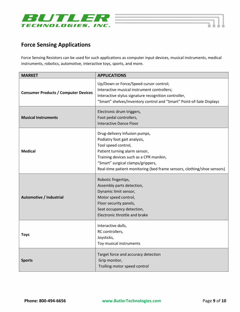
Force Sensing Applications
Force Sensing Resistors can be used for such applications as computer input devices, musical instruments, medical
instruments, robotics, automotive, interactive toys, sports, and more.
MARKET APPLICATIONS
Consumer Products / Computer Devices
Up/Down or Force/Speed cursor control;
Interactive musical instrument controllers;
Interactive stylus signature recognition controller,
“Smart” shelves/inventory control and “Smart” Point-of-Sale Displays
Musical Instruments
Electronic drum triggers,
Foot pedal controllers,
Interactive Dance Floor
Medical
Drug-delivery Infusion pumps,
Podiatry foot gait analysis,
Tool speed control,
Patient turning alarm sensor,
Training devices such as a CPR manikin,
“Smart” surgical clamps/grippers,
Real-time patient monitoring (bed frame sensors, clothing/shoe sensors)
Automotive / Industrial
Robotic fingertips,
Assembly parts detection,
Dynamic limit sensor,
Motor speed control,
Floor security panels,
Seat occupancy detection,
Electronic throttle and brake
Toys
Interactive dolls,
RC controllers,
Joysticks,
Toy musical instruments
Sports
Target force and accuracy detection
Grip monitor,
Trolling motor speed control

Phone: 800-494-6656 www.ButlerTechnologies.com Page 10 of 10
Application Examples Blockage Sensor for Drug-Delivery Infusion Pump/IV
Sensor for Foot Pressure Mapping Kiosks
Force Sensors can be used to sense and map the various pressure points on human feet in order so custom orthotics can be prescribed. In the case of a foot pressure mapping kiosk, a force sensing resistor array of more than 2,000 individual sensors provides a detailed output so the custom software can accurately analyze the person’s foot pressure points.
PRODUCT USE: All statements, technical information and recommendations contained in this document are based upon tests or experience that Butler Technologies, Inc. believes are reliable. However, many factors beyond Butler Technologies’ control can affect the use and performance of a Force Sensing Resistor (FSR) in a particular application, including the conditions under which the product is used and the time and environmental conditions in which the product is expected to perform. Since these factors are uniquely within the user’s knowledge and control, it is essential that the user evaluate the Butler Technologies FSR to determine whether it is fit for a particular purpose and suitable for the user’s application.
Portions of the content in this Technical Guideline have been provided through the courtesy of Sensitronics LLC and MSD Consumer Care, Inc.
If a blockage occurs in the patient’s IV line, the
tubing within the pump expands. The sensor
detects this expansion by sensing the pressure
applied on the sensor by the tubing. The sensor
then triggers an alarm to alert medical
personnel of the blockage.