Embed Size (px)
Citation preview

FORCE RIPPLE COMPENSATION OF LINEAR
SYNCHRONOUS MOTORS
Christof Röhrig
Asian Journal of Control
Vol. 7, No.1, pp. 1-11, March 2005


Asian Journal of Control, Vol. 7, No.1, pp. 1-11, March 2005 1
Manuscript received A? 1?, 2004; accepted ??, 2004.
Christof Röhrig is with Department of Computer Science,
University of Applied Sciences Dortmund, D-44227 Dort-
mund, Germany.
Manuscript received April 9, 2004; accepted June 16, 2004.
The author is with Department of Computer Science, Uni-
versity of Applied Sciences Dortmund, D-44227 Dortmund,
Germany.
FORCE RIPPLE COMPENSATION OF LINEAR
SYNCHRONOUS MOTORS
Christof Röhrig
ABSTRACT
Linear synchronous motors are finding expanded use in high-perform-
ance applications where high speed and high accuracy is essential. The main
problem in improving the tracking performance of linear synchronous mo-
tors is the presence of force ripple caused by mismatched current waveforms
and unbalanced motor phases or amplifier gains. This paper presents a
method to optimize the waveform of the phase currents in order to generate
smooth force. The optimized current waveforms produces minimal copper
losses and maximize motor efficiency. The waveforms are implemented in a
waveform generator of the motion controller and approximated with Fourier
series. The optimization method consist of three stages. In every stage, dif-
ferent harmonics of the force ripple are reduced. A comparison of the track-
ing performance with optimized waveforms and with sinusoidal waveforms
shows the effectiveness of the proposed method.
KeyWords: Motor control, force ripple, linear synchronous motors, opti-
mization.
I. INTRODUCTION
Permanent magnet (PM) linear synchronous motors
(LSM) are beginning to find widespread industrial appli-
cations, particularly for tasks requiring a high precision in
positioning such as various semiconductor fabrication and
inspection processes [1]. PM LSMs have better perform-
ance and higher power density than their induction coun-
terparts [2]. PM LSMs have a significant application po-
tential for a wide range of industrial applications [3-5].
The main benefits of PM LSMs are the high force density
achievable and the high positioning precision and accu-
racy associated with the mechanical simplicity of such
systems. The electromagnetic force is applied directly to
the payload without any mechanical transmission such as
chains or screw couplings. This greatly reduces nonlin-
earities and disturbances caused by backlash and addi-
tional frictional forces [6]. Today’s state-of-the-art linear
motors can achieve velocities up to 10m/s and accelera-
tions of 25g [7].
The more predominant nonlinear effects underlying a
PM LSM system are friction and force ripple arising from
imperfections in the underlying components [8]. In order
to avoid force ripple, different methods have been devel-
oped. In [9], a force ripple model is developed and identi-
fication is carried out with a force sensor and a fric-
tionless air bearing support of the motor carriage. In [10],
several techniques of torque ripple minimization for ro-
tating motors are reviewed. The design of linear motors
can be adapted to reduce force ripple. The cost of reduc-
ing force ripple by means of motor design is a decrease of
the mean force [11]. In [12], a neuronal-network based
feedforward controller is proposed to reduce the effect of
force ripple. Position-triggered repetitive control is pre-
sented in [13]. Other approaches are based on disturbance
observers [14,15], iterative learning control [16] or adap-
tive control [17,8,18]. The main problem in adaptive con-
trol is the low signal-to-noise ratio at high motor speeds
[19]. In [20], a force ripple compensation method for PM
LSM systems with electronic commutated servo amplifi-
ers was presented. A model based method was chosen,
because force ripple is a highly reproducible and
time-invariant disturbance [21]. The parameters of the
force ripple are identified in an offline procedure. The

2 Asian Journal of Control, Vol. 7, No. 1, March 2005
proposed method applies a feedforward controller for
compensation of force ripple and friction. The proposed
compensation method reduces the force ripple produced
by the imperfections of the underlying components, par-
ticularly non-optimal commutation of phase currents in
the servo amplifier. The drawback of controller-based
compensation methods in conjunction with electronic
sensor-based commutation is the non optimal current ex-
citation of the motor. Imperfect commutation of the phase
currents produces additional heat in the phase windings
and therefore reduces the motor efficiency.
In this paper, a force ripple compensation method for
software commutated servo amplifiers is proposed. The
additional input signal of a software commutated ampli-
fier is used to optimize the operation of the motor. The
paper proposes a method for design of the phase current
commands for minimization of force ripple and maximi-
zation of motor efficiency. The waveforms of the phase
currents are optimized in order to get smooth force and
minimal copper losses. In order to optimize the current
waveforms, the force functions of the phases are identi-
fied. The identification is performed by measuring the
control signals in a closed position control loop. The
waveform generation is integrated in the software com-
mutation module of the motion controller. The optimized
current waveforms are approximated with Fourier series.
This paper extends the work the author has presented in
[22] and [23].
II. EXPERIMENTAL SETUP
2.1 Linear motor
The motors considered here are PM LSM with epoxy
cores. A PM LSM consists of a secondary and a moving
primary. There are two basic classifications of PM LSMs:
epoxy core (i.e. non-ferrous, slotless) and iron core. Ep-
oxy core motors have coils wound within epoxy support.
These motors have a closed magnetic path through the
gap since two magnetic plates “sandwich” the coil as-
sembly [24]. Epoxy core linear motors can reach very
high dynamics and accuracy. This type of motor have the
highest force-to-inertia ratio [1]. Epoxy core LSMs are
key components of semiconductor manufacturing [7].
Figure 1 shows an unmounted PM LSM with epoxy core.
The secondary induces a multipole magnetic field in the
air gap between the magnetic plates. The magnet assem-
bly consists of rare earth magnets, mounted in alternate
polarity on steel plates. The electromagnetic thrust force
is produced by the interaction between the permanent
magnetic field in the secondary and the magnetic field in
the primary driven by the phase currents of the servo am-
plifier. The linear motor under evaluation is a current-
controlled three-phase motor driving a carriage supported
by roller bearings. The motor drives a mass of total 1.5kg
and is vertical mounted (Fig. 2).
2.2 Servo amplifier
The servo amplifiers employed in the setup are PWM
(pulse width modulation) types with closed current
control loop. Software commutation of the three phases is
performed in the motion controller by means of a position
encoder. This commutation method requires two current
command signals from the controller. The initialization
routine for determining the phase relationship is part of
the motion controller. The third phase current depends on
the others, because of the star connection of the motor
windings.
C A Bi i i= − − (1)
Fig. 1. Anorad LE linear motor [24].
Fig. 2. Experimental setup.

Christof Röhrig: Force Ripple Compensation of Linear Synchronous Motors 3
The star connection is the most common configura-
tion in three-phase motors [25]. The neutral of the star is
not brought out. The three external lines of the star are
connected to a half bridge circuit. The collection of three
half bridges is called a three-phase bridge. Only six
power electronic devices are needed in a three-phase
bridge, this is minimal compared to any other number of
phases. A two-phase motor needs eight power electronic
devices.
Figure 3 shows the block diagram of a software
commutated servo amplifier. The maximum of the ampli-
fier input signals uA, uB (±10V) correlates to the peak
currents of the current loops. In the setup, the peak cur-
rents of the amplifier are 25A. The PWM works with a
switching frequency of 24kHz. The current loop band-
width is specified with 2.5kHz [26]. Dynamics of the
amplifier will not be considered as they play a minor role
in the dynamics of the whole system.
III. SYSTEM MODELING
The thrust force is produced by interaction between
the permanent magnetic field in the secondary and the
electromagnetic field of the phase windings. The thrust
force is proportional to the magnetic field and the phase
currents iA, iB, iC. The back-EMF (electromotive force)
induced in a phase winding (eA, eB, eC) is proportional to
the magnetic field and the speed of the motor. The total
thrust force Fthrust is the sum of the forces produced by
each phases:
( ) { }thrust p pp
x F e x i p A B C= ; ∈ , ,∑� (2)
The back-EMF waveforms p
e
x�
can also be interpreted
as the force functions of the phases (KMp(x)).
( ) { }pthrust M p
p
F K x i p A B C= ; ∈ , ,∑ (3)
There are two types of position dependent distur-
bances: cogging force and force ripple. Cogging is a
magnetic disturbance force, that is caused by attraction
between the PMs and the iron part of the primary. The
force depends on the relative position of the primary with
respect to the magnets, and it is independent of the motor
current. Cogging is negligible in motors with iron-less
primaries [24].
Force ripple is an electromagnetic effect and causes a
periodic variation of the force constant. There are two
physical phenomena which lead to force ripple: Reluc-
tance force and harmonics in the electromagnetic force.
Reluctance force occurs only in motors with interior
mounted PMs. In this type of motor, the reluctance of the
motor is a function of position. The self inductance of the
phase windings varies with position of the primary with
respect to the secondary. When current flows, this causes
a position dependent force. If PMs are surface mounted,
reluctance is constant and reluctance force is negligible
[11].
In ironless and slotless motors, the only source of
force ripple are harmonics in the electromagnetic force.
Only if the back-EMF waveforms are sinusoidal and bal-
anced, symmetric sinusoidal commutation of the phase
currents produces smooth force. Force ripple occurs if the
motor current is different from zero, and its absolute
value depends on the required thrust force and the relative
position of the primary with respect to the secondary.
There are several sources of force ripple:
• Motor
− Harmonics of back-EMFs
− Amplitude imbalance of back-EMFs
− Phase imbalance of back-EMFs
• Amplifier
− Offset currents
− Imbalance of current gains
Fig. 3. Block diagram of a software commutated servo amplifier.
uA
Current Measurement
uB
CurrentController
PowerAmplifierPWM Linear MotorCurrent
Controller
Phase CurrentCommands
iA
iB
iC

4 Asian Journal of Control, Vol. 7, No. 1, March 2005
Offset currents lead to force ripple with the same pe-
riod as the commutation period. This force ripple is inde-
pendent of the desired thrust force. Amplitude or phase
imbalance of the motor and imbalance of amplifier gains
lead to force ripple with half commutation period which
scale in direct proportion to the desired thrust force. A kth
order harmonic of a back-EMF produces (k − 1)th
and (k
+ 1)th order harmonic force ripple, if sinusoidal currents
are applied.
Force ripple with the same period as the commuta-
tion period is independent of the desired current, all
higher order harmonics scale in direct proportion to the
desired current, because of the linearity of the force
Eq. (2). Figure 4 shows the block diagram of a servo sys-
tem with PM LSM. The friction force is modeled with a
kinetic friction model. In the kinetic friction model, the
friction force is a function of velocity only.
IV. COMPENSATION OF FORCE RIPPLE
The method for force ripple compensation consist of
three stages. In every stage, different harmonics of the
ripple spectrum are reduced. In order to optimize the
waveforms of the currents, identification of the force
functions KMp(x) is essential. The main idea of the pro-
posed method is to identify the force functions in a closed
position control loop by measuring the control signal u of
the position controller at a constant load force Floak as a
function of the position x. In the experimental setup, the
constant load force is produced by the force of gravitation.
In order to avoid inaccuracy by stiction, the measurement
is achieved with moving carriage. The position of the
carriage is obtained from an incremental linear optical
encoder with a measurement resolution of 0.1µm.
4.1 Experimental analysis of force ripple
In order to analyze the force ripple of the motor, a
sinusoidal reference current is applied:
2( ) sin( ( ))
3A Au u u x o,ϑ = ϑ +
2 2π( ) sin ( )
3 3B Bu u u x o
⎛ ⎞,ϑ = ϑ + +⎜ ⎟⎝ ⎠
0with ( ) ( )p
x x x
πϑ = −τ
(4)
where uA, uB are the current commands of the two phases,
u is the output of the position controller (force command),
x is the position of the carriage, τp is the pole pitch and x0
is the zero position with maximum force. In the first stage,
the DC components of the command signals (oA, oB) are
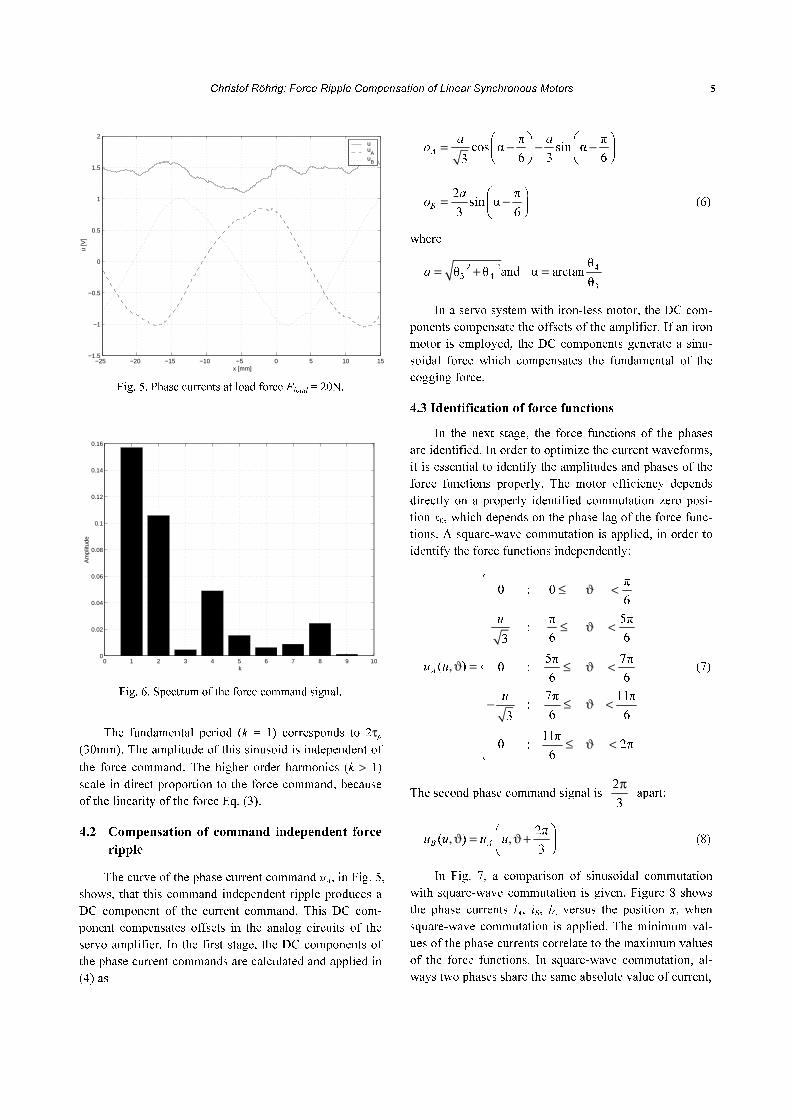
chosen equal zero. Figure 5 shows the control signals u,
uA, uB versus the position x. The ripple on the force com-
mand signal u is caused by force ripple. The controller
compensates the force ripple by changing the force com-
mand over the position. If the speed of the motor is high,
the force ripple increases the tracking error.
Frequency domain analyses of the force command
indicates, that the fundamental corresponds to the com-
mutation period 2τp. In order to estimate the parameters
of the ripple, a least square estimation of the model
parameters (5) was applied. A least square estimation is
chosen, because noise overlays the force command signal.
1 2( ) θ θf x x, = +θ
2 1 2 2
1
θ sin π θ cos πτ τ
N
k kk p p
x xk k+ +
=
⎛ ⎞⎛ ⎞ ⎛ ⎞⎜ ⎟+ +⎜ ⎟ ⎜ ⎟⎜ ⎟ ⎜ ⎟⎜ ⎟
⎝ ⎠ ⎝ ⎠⎝ ⎠∑ (5)
where θk are the estimated parameters. The sum of load
force and friction is estimated in θ1. The modeled spring
force (θ2) is necessary, because the control signal rises
with rising positions (this is caused by wire chains).
Figure 6 shows the amplitudes of the sinusoids
2 2
2 1 2 2θ θk k+ ++ versus the order of the harmonics k.
Fig. 4. Nonlinear model of a PM LSM servo system.
1
m
Fthrust
Ffriction
Fload
xx x
Position
Phase CurrentCommands
ServoAmplifier
F=f(i ,i ,i ,x)A B Cu
B
uA
iA
iB
iC
Christof Röhrig: Force Ripple Compensation of Linear Synchronous Motors 5
Fig. 5. Phase currents at load force Fload = 20N.
Fig. 6. Spectrum of the force command signal.
The fundamental period (k = 1) corresponds to 2τp (30mm). The amplitude of this sinusoid is independent of
the force command. The higher order harmonics (k > 1)
scale in direct proportion to the force command, because
of the linearity of the force Eq. (3).
4.2 Compensation of command independent force
ripple
The curve of the phase current command uA, in Fig. 5,
shows, that this command independent ripple produces a
DC component of the current command. This DC com-
ponent compensates offsets in the analog circuits of the
servo amplifier. In the first stage, the DC components of
the phase current commands are calculated and applied in
(4) as
π πcos α sin α
6 3 63A
a a
o
⎛ ⎞ ⎛ ⎞= − − −⎜ ⎟ ⎜ ⎟⎝ ⎠ ⎝ ⎠
2 πsin α
3 6B
a
o
⎛ ⎞= −⎜ ⎟⎝ ⎠
(6)
where
2 2 4
3 4
3
θand α arctanθ θ
θa = + =
In a servo system with iron-less motor, the DC com-
ponents compensate the offsets of the amplifier. If an iron
motor is employed, the DC components generate a sinu-
soidal force which compensates the fundamental of the
cogging force.
4.3 Identification of force functions
In the next stage, the force functions of the phases
are identified. In order to optimize the current waveforms,
it is essential to identify the amplitudes and phases of the
force functions properly. The motor efficiency depends
directly on a properly identified commutation zero posi-
tion x0, which depends on the phase lag of the force func-
tions. A square-wave commutation is applied, in order to
identify the force functions independently:
π0 : 0
6
π 5π:
6 63
5π 7π( ) 0 :
6 6
7π 11π:
6 63
11π0 : 2π
6
A
u
u u
u
⎧ ≤ ϑ <⎪⎪⎪ ≤ ϑ <⎪⎪⎪,ϑ = ≤ ϑ <⎨⎪⎪
− ≤ ϑ <⎪⎪⎪
≤ ϑ <⎪⎩
(7)
The second phase command signal is 2
3
π apart:
2π( )
3B Au u u u
⎛ ⎞,ϑ = ,ϑ +⎜ ⎟⎝ ⎠
(8)
In Fig. 7, a comparison of sinusoidal commutation
with square-wave commutation is given. Figure 8 shows
the phase currents iA, iB, iC versus the position x, when
square-wave commutation is applied. The minimum val-
ues of the phase currents correlate to the maximum values
of the force functions. In square-wave commutation, al-
ways two phases share the same absolute value of current,
−25 −20 −15 −10 −5 0 5 10 15−1.5
−1
−0.5
0
0.5
1
1.5
2
x [mm]
u [V
]
u u
A u
B
0 1 2 3 4 5 6 7 8 9 100
0.02
0.04
0.06
0.08
0.1
0.12
0.14
0.16
k
Am
plitu
de

6 Asian Journal of Control, Vol. 7, No. 1, March 2005
Fig. 7. Sinusoidal and square-wave commutation.
which depends on the force command u and the current
gains of the amplifier KSp.
{ }3
pp S
u
i K p A B| | = ; ∈ , (9)
Since only two phase currents are independent, the force
equation can be described as:
( ) ( )thrust A A B BF K u K u= ϑ + ϑ (10)
where KA(ϑ) and KB(ϑ) are the force functions of the cur-
rent commands uA and uB respectively.
π π( ) :
6 6
π π( ) :
3 6 2
( ) 5π 7π( ) :
6 6
7π 9π( ) :
6 6
B
A
thrust
B
A
K
KF
uK
K
⎧ ϑ − ≤ ϑ <⎪⎪⎪ ϑ ≤ ϑ <⎪⎪= ⎨ϑ ⎪− ϑ ≤ ϑ <⎪⎪⎪− ϑ ≤ ϑ <⎪⎩
(11)
Figure 9 shows the identified force functions. Sinu-
soids are applied to approximate the force functions, be-
cause the back-EMFs of the motor are nearly sinusoidal.
4.4 Current waveform optimization
Aim of the current waveform optimization is to ob-
tain reference waveforms of the phase currents, which
generate smooth force. Inspection of the force Eq. (10)
reveals that there are an infinite number of waveforms
that generates smooth force. Therefore a secondary con-
dition has to be applied. Since one problem of epoxy-core
PM LSM is overheating, the logical choice is to minimize
Fig. 8. Square-wave commutation.
the winding losses. The problem is formulated as con-
strained optimization. The constraint of the optimization
is a position independent force
( ) ( ) ( )thrust A A B B FF K u K u K u f= ϑ + ϑ = ≠ ϑ (12)
where KF is a freely eligible constant and u is the force
command. The winding losses can be written as
2( ) ( ) { }cu p p
p
P x R i x p A B C= ; ∈ , ,∑ (13)
where Rp is the resistance of phase winding p. In assump-
tion of symmetric winding resistances RA = RB = RC and
servo amplifier gains KSA = KSB
, the functional to be
minimized can be written as
2 2( )A B A B A Bf u u u u u u, = + + (14)
If the resistances are unsymmetric and/or the gains
are unequal and known, (14) has to be adapted to meet the
requirements. In case of small unsymmetric resistances
and gains, the minimization of (14) minimizes the wind-
ing losses approximately. After substituting (12) in (14)
the optimized waveforms can be obtained by minimizing
(14)
( )0A B
A
A
f u uu
u
∂ ,= =∂
( )0B B
B
B
f u uu
u
∂ ,= =∂
(15)
as
1
2
2 2
( ) ( )( )
( ) ( ) ( ) ( )
A B
A F A
A B A B
K Ku u K u o
K K K K
ϑ − ϑ,ϑ = +
ϑ + ϑ − ϑ ϑ
0 30 60 90 120 150 180 210 240 270 300 330 360
−0.6
−0.4
−0.2
0
0.2
0.4
0.6
ϑ [mm]
uA(1
, ϑ)
square−wave commutationsinusoidal commutation
−25 −20 −15 −10 −5 0 5 10 15−3
−2
−1
0
1
2
3
x [mm]
i A, i
B, i
C [A
]
iA
iB
iC

Christof Röhrig: Force Ripple Compensation of Linear Synchronous Motors 7
1
2
2 2
( ) ( )( )
( ) ( ) ( ) ( )
B A
B F B
A B A B
K Ku u K u o
K K K K
ϑ − ϑ,ϑ = +
ϑ + ϑ − ϑ ϑ
(16)
where oA, oB are the DC components obtained form (6).
In Fig. 10, the optimized phase current waveforms
are shown. Figure 11 compares the ripple of the force
commands by use of different commutation functions.
The dashed line shows the force command when a sinu-
soidal commutation plus offset compensation is employed
(Eq. (4)). The solid line shows the force command when
optimized waveforms are applied. The ripple of the force
command is significantly reduced when the optimized
waveforms are applied. The optimized waveforms maxi-
mize the motor efficiency by minimizing the ohmic
winding losses.
Fig. 9. Identified force functions.
Fig. 10. Optimized waveforms.
Fig. 11. Force command signals with sinusoidal versus opti-
mized waveforms.
4.5 Unbalanced sinusoidal force functions
In special case of unbalanced sinusoidal force func-
tions
( ) sin( α )A k kK aϑ = ϑ + , ( ) sin( β )B k kK bϑ = ϑ + (17)
sinusoidal commutation functions can produce smooth
force:
( ) sin( α )A u u Au u u a o,ϑ = ϑ + +
( ) sin( β )B u u Bu u ub o,ϑ = ϑ + + (18)
In consideration of (12), we obtain:
k u k ua a b b=
α α β β πk u k u+ = + ± (19)
which leads to
2
3
k
u
k
ba
a= ,
2
3
k
u
k
ab
b= (20)
and
3πα β
2u k= + ,
πβ α
2u k= + (21)
Figure 12 compares the unbalanced sinusoidal com-
mutation functions with the optimal commutation func-
tions. In both cases, the functions produces smooth force.
In Fig.13, the force commands for both cases are com-
pared. The optimized commutation functions lead to a
slightly lower ripple.
−25 −20 −15 −10 −5 0 5 10 15−15
−10
−5
0
5
10
15
x [mm]
kA, k
B [N
/ V
]
kA
kB
−25 −20 −15 −10 −5 0 5 10 15
−1
−0.8
−0.6
−0.4
−0.2
0
0.2
0.4
0.6
0.8
1
x [mm]
uA, u
B
uA
uB
−25 −20 −15 −10 −5 0 5 10 151.2
1.25
1.3
1.35
1.4
1.45
1.5
1.55
1.6
x [mm]
u [V
]
sinusoidal waveformsoptimized waveforms

8 Asian Journal of Control, Vol. 7, No. 1, March 2005
4.6 Fine tuning of the waveforms
After optimization of the waveforms, the motor effi-
ciency is maximized, but the force command still consists
of some higher order ripple. The higher order ripple is
caused by unmodeled harmonics of the force functions. In
order to reduce some of the higher order ripple, a fine
tuning of the waveforms is performed. The main idea of
the fine tuning algorithm is to measure the phase current
control signals at constant load force. The fine tuning is
performed with previously optimized waveforms, in order
to maximize motor efficiency. The still remaining higher
order ripple of the force command modulates the opti-
mized waveforms. The fine tuning algorithm approxi-
mates the shapes of the measured phase command signals
Fig. 12. Commutation functions in case of sinusoidal force
functions.
Fig. 13. Command signals with unbalanced sinusoidal com-
mutation functions and optimal commutation func-
tions.
with Fourier series. Figure 14 compares the measured
phase command signals with the approximation. In Fig.
15, a comparison of commutation functions of the second
stage with the third stage is given.
3 3
2( ) (sin( ) sin(3 α )
3Au u u a,ϑ = ϑ + ϑ +
5 5sin(5 α )) Aa o+ ϑ + +
2 2π( ) sin
3 3Bu u u
⎛ ⎛ ⎞,ϑ = ϑ +⎜ ⎜ ⎟⎝ ⎠⎝
3 3 5 5sin(3 β ) sin(5 β ) Bb b o⎞+ ϑ + + ϑ+ +⎟⎠
(22)
Figure 16 compares the command signal spectrum of
the optimization process. The upper left graph shows the
spectrum before any optimization is applied. The upper
right graph shows the spectrum after the offset compensa-
tion is applied. The fundamental is significantly reduced.
Fig. 14. Fine tuned waveforms.
Fig. 15. Force command signals with optimized versus fine
tuned waveforms.
−25 −20 −15 −10 −5 0 5 10 15
−1
−0.8
−0.6
−0.4
−0.2
0
0.2
0.4
0.6
0.8
1
x [mm]
uA, u
B
uA optimized
uB optimized
uA sinusoidal
uB sinusoidal
−25 −20 −15 −10 −5 0 5 10 151.2
1.25
1.3
1.35
1.4
1.45
1.5
1.55
1.6
x [mm]
u [V
]
unbalanced sinusoidaloptimized
−25 −20 −15 −10 −5 0 5 10 15
−1
−0.8
−0.6
−0.4
−0.2
0
0.2
0.4
0.6
0.8
1
x [mm]
uA, u
B [V
]
measurement approximation
−25 −20 −15 −10 −5 0 5 10 151.2
1.25
1.3
1.35
1.4
1.45
1.5
1.55
1.6
x [mm]
u [V
]
optimizationfine tuning

Christof Röhrig: Force Ripple Compensation of Linear Synchronous Motors 9
Fig. 16. Spectrum of the command signal.
In the lower left graph, the spectrum of the force com-
mand of the optimized waveforms is shown. This stage
reduces the 2nd
order harmonics. The lower right graph
shows the spectrum of the force command for fine tuned
waveforms. This last stage reduces the 2nd
and 4th
order
harmonics. After the fine tuning of the waveforms, no
dominant harmonic exists in the force command.
4.7 Controller design
Figure 17 shows the block diagram of the servo con-
trol system. In order to achieve a better tracking per-
formance, a feedforward controller is applied. Feedback
control without feedforward control always introduces a
phase lag in the command response. Feedforward control
sends an additional output, besides the feedback output,
to drive the servo amplifier input to desired thrust force.
The feedforward control compensates the effect of the
carriage mass and the friction force. The friction force is
modeled by a kinetic friction model and identified with
experiments at different velocities. The mass of the car-
riage is identified with a dynamic least square algorithm.
The stability of the system is determined by the feedback
loop. The compensation of the force ripple is performed
in the waveform generator with Fourier series approxima-
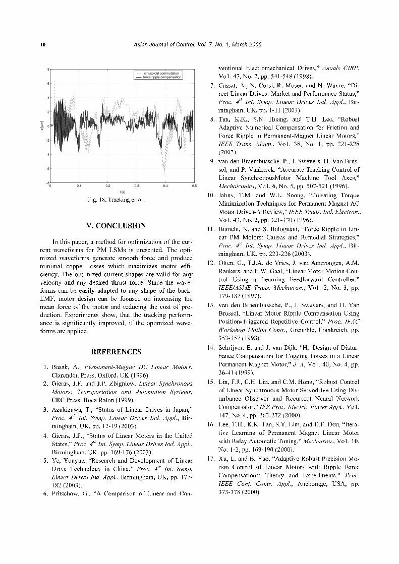
tion. Figure 18 compares the tracking error of a move-
ment without ripple compensation with the movement
with ripple compensation. In this measurement, the car-
riage moves from position − 25mm to position 15mm and
back to position − 25mm with vmax
= 200mm/s. If the rip-
ple compensation is applied, the tracking error is reduced
significantly.
Fig. 17. Controller design.
1 2 3 4 5 6 7 8 90
2
4
6
8
10
12Without Optimization
Am
plitu
de [%
]
1 2 3 4 5 6 7 8 90
2
4
6
8
10
12Step 1
Am
plitu
de [%
]
1 2 3 4 5 6 7 8 90
2
4
6
8
10
12Step 2
Am
plitu
de [%
]
1 2 3 4 5 6 7 8 90
2
4
6
8
10
12Step 3
Am
plitu
de [%
]
CurrentsPhase CurrentCommands
x
PositionPositionFeedbackControl
WaveformGenerator
ReferencePositionx
ref ServoAmplifier
LinearMotor
FeedforwardControl
ufb
uff
e
uB
uA
iA
iB
iC
10 Asian Journal of Control, Vol. 7, No. 1, March 2005
Fig. 18. Tracking error.
V. CONCLUSION
In this paper, a method for optimization of the cur-
rent waveforms for PM LSMs is presented. The opti-
mized waveforms generate smooth force and produce
minimal copper losses which maximizes motor effi-
ciency. The optimized current shapes are valid for any
velocity and any desired thrust force. Since the wave-
forms can be easily adapted to any shape of the back-
EMF, motor design can be focused on increasing the
mean force of the motor and reducing the cost of pro-
duction. Experiments show, that the tracking perform-
ance is significantly improved, if the optimized wave-
forms are applied.
REFERENCES
1. Basak, A., Permanent-Magnet DC Linear Motors.
Clarendon Press, Oxford, UK (1996).
2. Gieras, J.F. and J.P. Zbigniew, Linear Synchronous
Motors: Transportation and Automation Systems,
CRC Press, Boca Raton (1999).
3. Azukizawa, T., “Status of Linear Drives in Japan,”
Proc. 4th
Int. Symp. Linear Drives Ind. Appl., Bir-
mingham, UK, pp. 12-19 (2003).
4. Gieras, J.F., “Status of Linear Motors in the United
States,” Proc. 4th
Int. Symp. Linear Drives Ind. Appl.,
Birmingham, UK, pp. 169-176 (2003).
5. Ye, Yunyue, “Research and Development of Linear
Drive Technology in China,” Proc. 4th
Int. Symp.
Linear Drives Ind. Appl., Birmingham, UK, pp. 177-
182 (2003).
6. Pritschow, G., “A Comparison of Linear and Con-
ventional Electromechanical Drives,” Annals CIRP,
Vo1. 47, No. 2, pp. 541-548 (1998).
7. Cassat, A., N. Corsi, R. Moser, and N. Wavre, “Di-
rect Linear Drives: Market and Performance Status,”
Proc. 4th
Int. Symp. Linear Drives Ind. Appl., Bir-
mingham, UK, pp. 1-11 (2003).
8. Tan, K.K., S.N. Huang, and T.H. Lee, “Robust
Adaptive Numerical Compensation for Friction and
Force Ripple in Permanent-Magnet Linear Motors,”
IEEE Trans. Magn., Vo1. 38, No. 1, pp. 221-228
(2002).
9. van den Braembussche, P., J. Swevers, H. Van Brus-
sel, and P. Vanherck, “Accurate Tracking Control of
Linear SynchronousMotor Machine Tool Axes,”
Mechatronics, Vo1. 6, No. 5, pp. 507-521 (1996).
10. Jahns, T.M. and W.L. Soong, “Pulsating Torque
Minimization Techniques for Permanent Magnet AC
Motor Drives-A Review,” IEEE Trans. Ind. Electron.,
Vo1. 43, No. 2, pp. 321-330 (1996).
11. Bianchi, N. and S. Bolognani, “Force Ripple in Lin-
ear PM Motors: Causes and Remedial Strategies,”
Proc. 4th
Int. Symp. Linear Drives Ind. Appl., Bir-
mingham, UK, pp. 223-226 (2003).
12. Otten, G., T.J.A. de Vries, J. van Amerongen, A.M.
Rankers, and E.W. Gaal, “Linear Motor Motion Con-
trol Using a Learning Feedforward Controller,”
IEEE/ASME Trans. Mechatron., Vo1. 2, No. 3, pp.
179-187 (1997).
13. van den Braembussche, P., J. Swevers, and H. Van
Brussel, “Linear Motor Ripple Compensation Using
Position-Triggered Repetitive Control,” Proc. IFAC
Workshop Motion Contr., Grenoble, Frankreich, pp.
353-357 (1998).
14. Schrijver, E. and J. van Dijk. “H∞ Design of Distur-
bance Compensators for Cogging Forces in a Linear
Permanent Magnet Motor,” J. A, Vo1. 40, No. 4, pp.
36-41 (1999).
15. Lin, F.J., C.H. Lin, and C.M. Hong, “Robust Control
of Linear Synchronous Motor Servodrive Using Dis-
turbance Observer and Recurrent Neural Network
Compensator,” IEE Proc. Electric Power Appl., Vo1.
147, No. 4, pp. 263-272 (2000).
16. Lee, T.H., K.K. Tan, S.Y. Lim, and H.F. Dou, “Itera-
tive Learning of Permanent Magnet Linear Motor
with Relay Automatic Tuning,” Mechatron., Vo1. 10,
No. 1-2, pp. 169-190 (2000).
17. Xu, L. and B. Yao, “Adaptive Robust Precision Mo-
tion Control of Linear Motors with Ripple Force
Compensations: Theory and Experiments,” Proc.
IEEE Conf. Contr. Appl., Anchorage, USA, pp.
373-378 (2000).
0 0.1 0.2 0.3 0.4 0.5−8
−6
−4
−2
0
2
4
6
8
t [s]
e [µ
m]
sinusoidal commutationforce ripple compensation

Christof Röhrig: Force Ripple Compensation of Linear Synchronous Motors 11
18. Huang, S.N., K.K. Tan, and T.H. Lee, “Adaptive
Precision Control of Permanent Magnet Linear Mo-
tors,” Asian J. Contr., Vo1. 4, No. 2, pp. 193-198
(2002).
19. Seguritan, A. and M. Rotunno, “Adaptive Torque
Pulsation Compensation for a High-Torque DC
Brushless Permanent Magnet Motor,” Proc. 15th
IFAC World Congr. Automat. Contr., CD-ROM, p6,
Barcelona, Spanien (2002).
20. Röhrig, C. and A. Jochheim, “Identification and
Compensation of Force Ripple in Linear Permanent
Magnet Motors,” Proc. Amer. Contr. Conf., Arling-
ton, USA, pp. 2161-2166 (2001).
21. Röhrig, C. and A. Jochheim, “Motion Control of
Linear Permanent Magnet Motors with Force Ripple
Compensation,” Proc. 3rd
Int. Symp. Linear Drives
Ind. Appl., Nagano, Japan, pp. 478-483 (2001).
22. Röhrig, C. and A. Jochheim, “Motion Control of
Linear Synchronous Motors with Force Ripple Com-
pensation Uusing Current Shaping,” Proc. 15th
IFAC
World Congr. Automat. Contr., CD-ROM, p6, Barce-
lona, Spanien (2002).
23. Röhrig, C., “Current Waveform Optimization for
Force Ripple Compensation of Linear Synchronous
Motors,” Proc. 42nd
Conf. Decis. Contr., Maui, Ha-
waii, Vol. 6, pp. 5891-5896 (2003).
24. LE Series Linear Motor Systems, Motor Integration
Manual LEA, LEB, LEC & LEM Linear Motors,
Anorad Corporation (1999).
25. Hanselman, D.C., Brushless Permanent-Magnet Mo-
tor Design, McGraw-Hill, New York (1994).
26. High Voltage Brushless D.C. Servo Amplifier,
Hardware Maintenance Manual, Anorad Corporation
(1998).
Christof Röhrig received his Di-
ploma degree from the University
of Bochum, Germany, in 1993, and
his Doctor degree from the Univer-
sity of Hagen, Germany, in 2003,
both in electrical engineering. Be-
tween 1993 and 1997 he was Man-
ager Automated Systems Engineer-
ing at Reinoldus Transport- und Robotertechnik GmbH
Dortmund, Germany. From 1997 until 2003 he was with
the Control Systems Engineering Group at University of
Hagen. His research was focused on motor control,
eLearning and remote laboratories. Since 2003, he is
Professor of Computer Science at the University of Ap-
plied Sciences Dortmund, Germany. His current re-
search interests include motor control, robotics and
telematics.