Embed Size (px)
Citation preview
Version 3
FlaWARN Emergency Response & Preparedness Best Management Practices for Water & Wastewater Systems 1
Emergency Response and Preparedness
FlaWARN
Best Management Practices for
Water and Wastewater Systems
Version3, Updated 2013

Version 3
FlaWARN Emergency Response & Preparedness Best Management Practices for Water & Wastewater Systems
2
© 2013 University of Florida Center for Training,
Research and Education for Environmental Occupations
(UF/TREEO) for
Florida Water/wastewater Agency Response Network
3900 SW 63 Blvd
Gainesville, FL 32608
Permission granted for use by any State or Federal agency or any
WARN organization to use as part of their emergency operations plan.
Version 3
FlaWARN Emergency Response & Preparedness Best Management Practices for Water & Wastewater Systems
3
Acknowledgements
Editor’s Note:
Florida Water/Wastewater Agency Response Network (FlaWARN) is a water and wastewater
utility organization dedicated to assisting member utilities in restoration activities in the
aftermath of a disaster. The organization, through its member networks, coordinates emergency
response activities in Florida, and if needed outside of Florida. This document includes Best
Management Practices (BMPs) for Water/Wastewater Emergency Response that have been
prepared by FlaWARN members and compiled to more effectively meet the approaching
hurricane season.
As with all good emergency response plans, this compilation is a “living document” and we
welcome further input as more lessons are learned. FlaWARN members are encouraged to
provide comments via email to [email protected].
We would like to acknowledge the Florida Department of Environmental Protection and the
United States Environmental Protection for the grant that has made FlaWARN possible and to
the many utility organizations and individuals that have provided assistance with the
preparation of this document.
We would also like to recognize the following for their contributions.
FlaWARN Steering Committee 2007
Scott Kelly, Chairman, JEA At Large [email protected]
Gary Williams, Vice-Chairman,
Florida Rural Water Association FRWA [email protected]
Brad Jewell FSAWWA [email protected]
Ray Hanson, Orange County FWEA [email protected]
Tim McVeigh FWPCOA [email protected]
Ken Carter Florida Department Environmental Protection FDEP [email protected]
Brian Matthews, City of Palm Coast SEDA [email protected]
Richard Griswold, Destin Water Users At Large [email protected]
Brian Wheeler, TOHO At Large [email protected]
Special Thanks to Florida Rural Water Association Staff
Gary Williams
Bob McVay
Version 3
FlaWARN Emergency Response & Preparedness Best Management Practices for Water & Wastewater Systems 4
TREEO Staff
Carol Hinton, Associate Director
Laurie Brown, Coordinator
BMP Committee
Gary Williams
Scott Kelly
Richard Griswold
Ed Toby
BMP Authors
Gary Williams
Richard Griswold
Blane Collier
Danny Ashburn
Pat Henderson
Brian Matthews
Robert McVay
William Brandon
Kenny Williams
Sterling Carroll
Ed Cordova
Brian Wheeler
Craig West
Ray Gagnon
Patty DiPiero
BMP Editors
Carol Hinton, Associate Director, TREEO
Robert McVay P.E., Florida Rural Water Association
Center for Training, Research and Education
for Environmental Occupations (UF/TREEO)
The mission of UF/TREEO, Excellence in Environmental Education & Training, ensures that
Water and Wastewater operators receive up-to-date information that can be applied and used
directly in their jobs.

Version 3
FlaWARN Emergency Response & Preparedness Best Management Practices for Water & Wastewater Systems
5
Table of Contents
Chapter 1: Membership in the FlaWARN Disaster Recovery Organization .........................7
Chapter 2: Emergency Preparedness Planning Overview ................................................... 10
Chapter 3: Detailed Emergency Hurricane Procedures for
Water and Wastewater Facilities ....................................................................... 28
Chapter 4: Preparing Lift Stations for Hurricanes ............................................................... 32
Chapter 5: Guidelines for Response and Restoration of Water and Wastewater
Utility Services................................................................................................... 36
Chapter 6: Conducting Post Hurricane and Tornado Assessments ..................................... 43
Chapter 7: Contamination in Restoration of Utility Services 53
Chapter 8: Procedures for Response and Receiving Agencies for Restoration Activities .. 56
Chapter 9: Organizing Work for First Responders ............................................................. 61
Chapter 10: Loaning and Receiving Equipment in Responder Operations .......................... 74
Chapter 11: Operating Agreement for Loaning and Receiving Equipment .......................... 79
Chapter 12: Transport of Equipment, Materials and Personnel to Staging Areas ................. 83
Chapter 13: Effective Staging Area Set Up ..........................................................................100
Chapter 14: Dealing with Post-Hurricane Shock, Stress and Trauma ..................................102
Chapter 15: Power Outages and Procedures for Emergency Generator Installations ..........105
Chapter 16: Guidelines for Effective Rotation of Pumps, Generators and Tankers .............127
Chapter 17: Development of Exit Strategies for Responders ...............................................139
Chapter 18: Flood Preparation and Response .......................................................................142
A1: Weather/Hurricane Terms and Acronyms ........................................................153
A2: Glossary & Related Links .................................................................................156
A3: FlaWARN Water Security ................................................................................157
A4: Florida Division of Emergency Management ...................................................162
A5: FlaWARN Mutual Aid Agreement ...................................................................164
A6: Work Management Documentation ..................................................................168
A7: Forms for Loaning and Receiving Equipment ..................................................174
A8: Sample Press Releases ......................................................................................179
A9: Sample Employee Assistance Plans..................................................................190
A10: Boil Water Notice Guidelines ...........................................................................192
A11: Best Management Practices for Water Main Breaks and Repairs ....................200
A 12: Disinfecting Flooded Wells ..............................................................................202
A13: Best Management Practices for Bacteriological Disinfection of Water Mains 211
A 14: Restoring Electric Motors Flooded by Saltwater ..............................................215
References .........................................................................................................224
Version 3
FlaWARN Emergency Response & Preparedness Best Management Practices for Water & Wastewater Systems
6
Chapter 1: Membership in the FlaWARN Disaster Recovery Organization
FlaWARN and Storm Tracker Systems
Florida’s Water/Wastewater Agency Response Network, referred to as FlaWARN is a program
funded by the Florida Department of Environmental Protection (FDEP) with a grant from the US
Environmental Protection Agency (EPA). FlaWARN includes a formalized system of ‘utilities
helping utilities’ to address mutual aid during emergency situations such as hurricanes.
The goal of FlaWARN is to provide immediate relief for member utilities during emergencies.
FlaWARN works by matching personnel with the necessary tools and equipment to both assess
and assist impacted water and wastewater systems as quickly as possible until permanent
solutions to the devastation may be implemented. This method of assistance is analogous to
triage at a hospital.
FlaWARN assists its members with the following issues:
Recovery coordination
Resource inventory and availability status
Information exchange
Vulnerability assessment tools
Preparation protocols
Emergency Response Plan updates and checklists
Updated best management practices reference library
Up-to-date status reports
Pertinent legislation briefings
FlaWARN Database of Water & Wastewater Systems
FlaWARN is made up of volunteers from member utilities that coordinate with Florida
Department of Environmental Protection (FDEP) to obtain updated contact information for those
facilities not a member of FlaWARN. FlaWARN maintains and continuously updates
information on all its member utilities.
FDEP sources for obtaining this information are the FDEP representative on the steering
committee and the FlaWARN grant administrator in Tallahassee.
Generally, the individual FDEP districts maintain emergency contact spreadsheets that may
include more extensive information than systems want to have posted on the FDEP database
(such as personal cell phone numbers). This information can be requested from FDEP
representatives on an as-needed basis.

Version 3
FlaWARN Emergency Response & Preparedness Best Management Practices for Water & Wastewater Systems
7
FlaWARN will send messages to members 60 days prior to hurricane season, requesting all
members update their emergency contact information on the FlaWARN website. Prior to
hurricane season, utilities will be notified about changes to the website from last season and
encouraged to fully utilize any new capabilities.
As the FlaWARN website is developed, additional capability may be incorporated to provide
expanded utility system information.
FlaWARN Operation during an Emergency
When there is knowledge of an event in advance, such as a hurricane, the steering committee
starts pre-planning three to four days out. As the hurricane is tracked, utilities out of the path of
the storm gear up to help the targeted areas. Member utilities are able to request assistance
through the FlaWARN web site.
Since electricity is often out during an emergency, FlaWARN administrators and steering
committee members attempt to contact, using emergency contact information, all utilities in the
area of the storm and determine their needs. Contacting individual utilities is closely coordinated
with FRWA. Administrators will then post any needs to the web page. This is an innovative
process because it allows member utilities to match their available resources to requests for
assistance.
FlaWARN’s mission is to get the correct resources to the appropriate location within the first
days after an event. FlaWARN gears up without any notice, using the contact information on its
web page and responds to both man-made emergencies as well as natural disasters.
FlaWARN Organizational Structure
A steering committee provides leadership for FlaWARN. It is composed of representatives of
five state water/wastewater professional organizations including: FSAWWA, FWEA, FWPCOA,
FRWA, SEDA; three at large members and a representative from FDEP. The University of
Florida Center for Training, Research and Education for Environmental Occupations
(UF/TREEO) is responsible for implementing the program.
Florida Department of Environmental Protection Storm Tracker
The Storm Tracker system is a FDEP web based program designed to provide status for all
Florida water and wastewater utilities. Systems in impacted counties will be asked by FDEP to
update the website with their current operational status and the needs of the utility can be
submitted here which will greatly expedite the FlaWARN updating process and the resultant
response efforts. The Storm Tracker website address is:
http://tlhdwf2.dep.state.fl.us/stormtracker/information.asp

Version 3
FlaWARN Emergency Response & Preparedness Best Management Practices for Water & Wastewater Systems
8
The FlaWARN organization encourages the full use of Storm Tracker in pre-storm messages to
member organizations. FlaWARN administration will monitor the Storm Tracker website to
ensure all utilities need assistance will be reached.
In addition to facility status, additional information is available from Storm Tracker, including
total number and power availability for treatment plants and lift stations. It should be noted that
in the aftermath of a storm, both FlaWARN and FDEP personnel would typically be present at
ESF-10 in the state EOC. These contacts can and should be used to pass information as needed
between FlaWARN and FDEP, including information obtained from Storm Tracker.
Pre-Storm Calls to All Water & Wastewater Systems within Likely Hurricane Track
Prior to storm landfall, the FlaWARN steering committee will assign members to contact
systems in the path of the approaching storm. This will be closely coordinated with FRWA.
FlaWARN representatives will attempt to verify contact information, including emergency after-
hours phone numbers; obtain information on the preparation status of each facility; inquire as to
assets available if the system is not impacted by the storm; and encourage systems to join
FlaWARN and execute the Mutual Aid Agreement if they have not already done so.
Obtain Tracking/Mission Number or Emergency Mutual Aid Contract Authorization
The FlaWARN steering committee will attempt to obtain a tracking/mission number from the
state or impacted county EOC prior to storm landfall. The request will then be confirmed,
updated, or deleted after storm landfall based on actual conditions. Obtaining a tracking or
mission number prior to storm landfall will facilitate response activities by ensuring responding
systems have authorization to proceed prior to departure, without having to request an initial
tracking number during the chaos that may exist in the affected EOC just after storm landfall.
Each utility should also coordinate with their local ECO regarding mission numbers and their
actions.
For interstate relief activities, an EMAC (Emergency Mutual Aid Compact) request and
authorization will need to be obtained from the governors of the receiving and providing states.
FlaWARN, FDEP, and FRWA personnel will coordinate efforts with state emergency response
staff to obtain authorization. For more information on EMAC go to:
http://www.emacweb.org/
FlaWARN Member List available at www.flawarn.org.

Version 3
FlaWARN Emergency Response & Preparedness Best Management Practices for Water & Wastewater Systems
9
Chapter 2: Emergency Preparedness Planning Overview
Introduction to Emergency Preparedness Planning
Disasters may strike at any time. However, being prepared for a particular disaster requires time,
training, financial resources, and a response plan. Emergency Preparedness for hurricanes
requires four primary considerations:
Actions taken before the storm
Actions taken during the storm
Actions taken after the storm
A program of scheduled maintenance to keep the plan effective and relevant.
Emergency Preparedness Planning Objectives
The purpose of Emergency Preparedness Planning is to identify those components of normal
operation disrupted by the emergency so the utility can respond appropriately and protect the
health of customers and the community.
Objectives of Emergency Planning
Quickly identify the emergency, and initiate timely and effective response actions
Quickly notify local, state, and federal agencies to assist in the response if needed
Determine if the water is not safe to drink or use and being able to rapidly notify
customers effectively of the situation and advise them of appropriate protective
action
Identify and prioritize wastewater facilities that have been impacted and that
present a threat to the public or to the receiving environment
Respond to and repair damage to minimize or prevent system down time.
Organizational Chart and Chain of Command Responsibilities
When an emergency occurs, there can be confusion, lack of coordination, and poor
communication. Timely and effective response can minimize the effects of an emergency. Often,
the initial response sets the tone for the entire emergency.
Having a chain of command that defines clear lines of authority and responsibilities for system
personnel during an emergency speeds up response time and helps eliminate confusion. System
Version 3
FlaWARN Emergency Response & Preparedness Best Management Practices for Water & Wastewater Systems
10
personnel need to know who to report the emergency to, who manages the emergency, who
makes decisions, and what their own responsibilities are.
Components of an Organizational Chart
Identification of staff, their job titles and to whom they report
Their responsibilities in the emergency response activities
The organizational chart should be accompanied by written procedures for quickly disseminating
information to appropriate parties. These components are described in the following sections.
Development of Personnel Rosters, Emergency Duty Assignments
A major hurricane can make communication with utility employees difficult or impossible. The
development of personnel rosters and pre-storm duty assignments (including pre-storm, during
storm and after-storm reporting responsibilities) can make this task manageable. Enhancements
to this list include the skill levels of personnel in water, wastewater areas, various utility
construction, electrical and electronic equipment.
At a minimum, the utility should maintain an updated list of each employee, their home
addresses and contact numbers. Additionally, rosters of contactors, outside agency emergency
personnel, and fuel and chemical vendors that may provide assistance should be prepared and
disseminated to people with decision making responsibilities prior to the storm.
Personnel and Emergency Staffing Responsibilities
How the response effort will be managed requires developing personnel and emergency staffing
responsibilities. After development of organizational charts that include the chain of command
with clear lines of authority and responsibilities; the standard operating procedures for the
emergency may be developed.
Procedures are written standard operating instructions, which describe special hurricane duty
assignments and are established for all facets of the storm preparation and response. These
procedures should include operating responsibilities for assessing, monitoring, reporting, and
staff responsibilities that include support functions such as handling communications and
providing meals. Most utilities will need to use personnel from other departments to handle
support functions during emergency operation.
No plan will be useful unless employees are trained in how to on its use. Once written
procedures are established; review of the plan with employees and mock drills are helpful and
reveal areas that need improvement. Drills should be conducted in cooperation with other
emergency agencies.

Version 3
FlaWARN Emergency Response & Preparedness Best Management Practices for Water & Wastewater Systems
11
Maintenance of the plan is essential and should be assigned to one individual who has
responsibility for updating the plan and providing updates to affected employees. Using the
systems approach of plan, do, check and act can ensure the plan is reviewed and updated
annually.
Components of Standard Operating Procedures
Operating Procedures are the core of an emergency preparedness plan. Procedures will include
base systems mapping and development of an operational inventory of all of operating facilities.
The following is a checklist that may be helpful in preparing the base system mapping
components:
Base System Mapping and Informational Requirements Checklist for
Performing a Base System Operational Assessment
Location Map (lift stations, wells, booster stations)
Location Directions (major intersections and street directions and GPS coordinates)
Facility Configurations (number of units, power service, nameplate info)
Valve Locations (major/minor valve for water and force mains)
Facility Relationships (relay pumping, force main interconnections)
Facility Redundancy (duplex, triplex, permanent generators)
Facility Emergency Equip (alt. electrical disconnects, pump-arounds)
Special Facility Requirements (plug configuration, special connections)
Facility Security (gate, electrical panel, wet well, pump house)
Mutual Aid and Inter-local Agreements
A significant hurricane might inflict damages that will exceed the utility’s ability to restore
normal service in a timely manner. Written agreements with other agencies and utilities can be
very helpful in this situation. Some of the best resources in an emergency are other
organizations, neighboring utilities and cities that may have equipment and/or staff that can used
temporarily.
In an emergency, demand for resources will come from many places and can exceed capacity.
The best way to access scarce resources in an emergency is through a Mutual Aid Agreement or
an Inter-local Agreement. Mutual Aid Agreements and Inter-local Agreements exist to provide
local jurisdictions with the opportunity to quickly exchange services during an emergency or
disaster and provide the framework for the procedures to be used for transfer and billing. These
types of agreements have distinct features.
A Mutual Aid Agreement (MAA) is general in nature and is basically an understanding that,
other jurisdictions will assist if resources are available during an emergency. The type of service
to be provided is frequently open ended.
Version 3
FlaWARN Emergency Response & Preparedness Best Management Practices for Water & Wastewater Systems
12
FlaWARN provides a generic Mutual Aid Agreements available on the web that can be quickly
implemented well before the time that assistance is needed. An example is provided in the
Appendix.
The American Water Works Association published a document, “Utilities Helping Utilities: An
Action Plan For Mutual Aid And Assistance Networks For Water And Wastewater Utilities”, By
Kevin Morley, American Water Works Association and Ray Riordan, California Utilities
Emergency Association, that includes a sample MAA and a comparison of three states MAAs
and their compliance to NIMS, FlaWARN is compliant in 12 of the 21 requirements. To access
this document go to:
http://www.awwa.org/Advocacy/Govtaff/Documents/Utilities_Helping_Utilities.pdf
An Inter-local Agreement is specific in perspective and it is more contractual in design. With an
Inter-local Agreement, specific services are agreed upon and provided under defined conditions.
An Inter-local Agreement provides a much clearer understanding of what support may be
received during an emergency or disaster, but is less flexible. Although highly recommended,
Inter-local Agreements may not provide any assurance in a time when large regions of the state
may be devastated.
Emergency Coordination with Emergency Agencies
Emergency coordination with local, state and federal emergency planning agencies is essential in
the development of an emergency preparedness plan. This planning consists of the development
of your plan in cooperation with the local county emergency operations manager and local law
enforcement agencies. This may include setting up procedures for identifying utility vehicles and
personnel that will include company identification (utility ID badges or identification) as well as
SERT IDs.
Coordination will also include emergency response planning, training, rehearsals, and mock
exercises with emergency planning agencies.
The Florida Rural Water Association provides Emergency Response Planning templates and
guidelines and training through its regular training programs.
Operational Preparedness and Response Plan(s)
Emergencies will exhibit a wide range of damages and severity. The level of severity will
determine the appropriate operational response actions. Emergency Preparedness Plans must
have provisions for quickly analyzing the emergency and methods to confirm and prioritize
appropriate response action. Assessing the severity of the damages and being able to
communicate them clearly to others will help system personnel keep their response efforts
effective. Response actions and repairs should be based on established written priorities. In some
cases, response activities will be dictated by public health or safety concerns such as hospitals,

Version 3
FlaWARN Emergency Response & Preparedness Best Management Practices for Water & Wastewater Systems
13
emergency shelters, nursing homes and emergency operation centers to maintain pressure, flow
and disinfection.
Each disaster-specific preparedness/response plan should incorporate the results, an assessment
of actions, resources, and equipment that can lessen the impact of such a disaster and temporarily
restore minimal levels of service.
Objectives of a Damage Assessment
Analyze and confirm the type and severity of damages
Identify resources that can be effectively used in mitigating damages
Take immediate actions to protect public health and safety
Take action to reduce injuries and system damage
Make repairs based on priority demand
Return the system to normal operation
Restoring the systems to normal operation is not the immediate goal, and many factors need to
be considered before returning to normal operation. For example:
Considerations in Achieving Normal Utility System Operation
The system is repaired to the point that it can meet demand.
The system operator has made a safety and operational inspection of all system
components and they are properly functioning.
The water system has been properly flushed, disinfected and pressure tested.
The water has been adequately tested in accordance with sampling regulations.
The water quality meets primary and secondary standards.
Adequate staff is available to operate and manage the system.
Federal, state, and local agencies support returning the system to normal
operations.
Vulnerability Assessment
As part of a viable emergency response plan, water system personnel should identify and assess
the vulnerability of each system component for natural emergencies. Community water systems
serving populations greater than 3,300 persons are required by Ch. 62-555 FAC to incorporate
the vulnerability assessment into emergency response planning. Vulnerability assessment is the
process by which the water system personnel evaluate each water system component for
weaknesses or deficiencies that may make the system susceptible to damage or failure during a
natural or man-made emergency under various operating scenarios.
In conducting the vulnerability assessment, the water system personnel must estimate how the
system and its facilities may be affected in emergency situations. Although not currently required

Version 3
FlaWARN Emergency Response & Preparedness Best Management Practices for Water & Wastewater Systems
14
by law, systems are strongly advised to perform the same vulnerability assessments for
wastewater facilities. This information is essential for determining what preventive actions or
improvements are needed and identifying the response actions to incorporate in the event of an
emergency.
Vulnerability Assessment Process
Identify and map the system’s components, to include water sources, treatment
facilities, pump-houses, storage reservoirs, transmission lines and distribution
lines, for wastewater collection systems, lift stations, forcemains, treatment
plants, and for water and wastewater systems key valves, electrical power
requirements and power service, communication systems, telemetry control, and
computer systems
Determine the level of severity for these systems based on the likelihood of a
major hurricane that inflicts significant damage and the response actions to be
implemented. Evaluate the potential effects on various types equipment.
Identify key emergency resources and personnel and how they are to be deployed.
Assess the impact of the disaster on the system’s operations personnel from both a
safety standpoint and the added stress of working in these conditions.
Define the system’s expectations or set performance goals for system components
for different severities of disaster.
Identify improvements that have already been made, and any additional ones
planned or proposed.
Standby Power Requirements
The major impact to utilities for any hurricane will be the loss of power. It is important then to
describe how the utility water system meets the standby power requirements required by FDEP
rules. The guidelines below are essential in facilitating a timely and effective restoration effort.
Identification of Power Requirements for Water/Wastewater Facilities
Describe facilities serviced by permanent standby power source and its location or
connection with two independent power feeds from separate substations.
Describe facilities where a portable standby power source will need to be
provided.
Describe auto-power transfers and audio-visual alarm system activation and the
operator(s) to be notified in the event any power source fails.
Document the number of motors, power requirements, horsepower, phase,
electrical provision (wye or delta), voltage, and amperage for each facility.
Determine the amount of fuel to maintain on site, and the amount of fuel to hold
in reserve under contracts with fuel suppliers, for operation of auxiliary power
sources and the maximum period of operation without refueling.
Version 3
FlaWARN Emergency Response & Preparedness Best Management Practices for Water & Wastewater Systems
15
Treatment Chemicals and Disinfectants
Hurricanes can significantly disrupt the ability of a utility to obtain chemicals essential to the
treatment process. It is important that the utility identify the amount of chemicals on hand and
the rate used in the treatment process. In the event of an impending hurricane, the utility must
identify the minimum amount of chemicals to maintain in inventory. The inventory will be
dependant upon the location and reliability of chemical suppliers, the status of impending
disasters, chemical storage capacity, and chemical availability.
Fiscal Planning Considerations
Fiscal planning will be required to obtain necessary equipment/supplies and specialized training.
Time should be allocated for meetings, drills and inspections. Good fiscal planning includes
cash reserves required to effectively operate in the event of an unexpected disaster.
Fund reserves are typically set by the utility’s bond resolution documents. Funds will include:
debt service fund (funds used to pay principle and interest for outstanding debt),
subordinated debt funds (funds used to pay principle and interest on short-term
borrowing)
construction fund (funds accumulated to pay for costs of acquisition and extension of the
system) utility plant improvement fund (funds used to pay for certain capital projects or
redemption of bonds
the rate stabilization fund (funds used to stabilize rates for future periods or for meeting
unanticipated capital or operating expenses.)
Most large utilities will have a fund set-aside called the “Rate Stabilization Fund.” The Rate
Stabilization Fund is built over time to a fixed amount using incoming proceeds. This fund is
used to stabilize the effects of rate shock caused by future planned capital improvements. These
funds are typically set at a dollar value that is both large enough to absorb rate shock and
sufficient to provide operating reserves in an emergency situation where incoming revenues may
be severely depleted.
Most large utilities will use a 10- to 15-year planning horizon and a 5- to 7-year capital
budgeting process. Capital projections are very accurate in the 3-year horizon and become less
accurate over the longer term. Making financial adjustments year to year using actual capital
expenditures and funds encumbered (payments yet to be made) allows the utility to plan cash
flows for both operating and capital programs within + 5 percent of planning projections during
a normal year.
Failure to plan for the devastating financial effects that a utility could experience based on a
large hurricane can quickly deplete operating reserves putting the utility’s ability to maintain
normal functions in jeopardy. Although monthly fees or revenue collected from customers’ will
be allocated differently, it is not uncommon for utilities to allocate as much as 30 percent of the
utility’s revenue to the payment of debt service and for future capital projects. Taxes or transfers

Version 3
FlaWARN Emergency Response & Preparedness Best Management Practices for Water & Wastewater Systems
16
to the city operating fund for publicly owned utilities could approach 25 percent. Without good
financial planning for this kind of crisis, operating funds will quickly disappear in the aftermath
of a disaster, putting extreme stress on cash reserves and making normal operations difficult.
Equipment, Parts and Tool Inventory Assessment and Procurement
Systematic planning of equipment acquisitions and the purchase of supplies are also critical. For
example, lumber for hurricane protection should be purchased during the first quarter of the year
to ensure proper supplies and lower costs. Changes in equipment storage and improvements to
systems should also take into account disaster response issues such as evacuation routes
vulnerability.
Thorough disaster preparedness, response, and restoration plans involve each facility and its
operations. Equipment must be kept in good working order by implementation of strict
preventive maintenance programs. Facilities and their operations must be ready at all times to
implement disaster response activities. This process involves proper planning at all levels of
operational activities.
Resource planning is another important tool for effective response. The most likely
contingencies should be taken into consideration when identifying the required types and
quantities of a particular product/material that should be on hand.
Essential Communication after a Disaster
In many emergencies the first step may be to communicate system status to the local EOC. This
requires that the person responsible for managing the emergency and making key decisions
assess the situation and initiate a series of actions based on the type and severity of the
emergency.
The local emergency management center is equipped with various types of emergency
communications equipment and may be in a position to provide valuable assistance with
notifying the public. A partnership with the local emergency manager should be established to
coordinate this assistance well in advance of hurricane season.
Larger systems may have a variety of people involved in the assessment and communication
functions. However, small systems may only have one person, usually the system operator, in
their chain of command. These systems will need to make sure each responsibility is clearly
defined so the person does not forget any task during an emergency.
Key Communication Responsibilities in an Emergency
Handle incoming phone calls and provide administrative support
Provide information to the public and media
Inform the customers and the media of the restoration actions
Version 3
FlaWARN Emergency Response & Preparedness Best Management Practices for Water & Wastewater Systems
17
Update the public on the system restoration and priority operations in the
field
Developing a Communication Plan
Every agency involved in restoration efforts will be involved in communications and public
relations whether intentional or not. An active communication plan can change communication
from an unneeded interruption and disruption of business to an alignment of emergency response
and communication activities that provide a needed flow of information to those that need it
most. Effective communication builds confidence and credibility in the agency’s response efforts
and continually allows monitoring information be made available to those that need it for both
decision-making and updated on the progress of agency efforts.
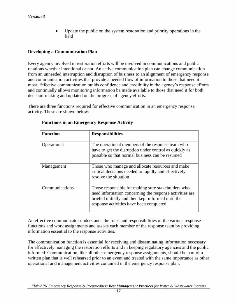
There are three functions required for effective communication in an emergency response
activity. These are shown below:
Functions in an Emergency Response Activity
Function Responsibilities
Operational The operational members of the response team who
have to get the disruption under control as quickly as
possible so that normal business can be resumed
Management Those who manage and allocate resources and make
critical decisions needed to rapidly and effectively
resolve the situation
Communications Those responsible for making sure stakeholders who
need information concerning the response activities are
briefed initially and then kept informed until the
response activities have been completed
An effective communicator understands the roles and responsibilities of the various response
functions and work assignments and assists each member of the response team by providing
information essential to the response activities.
The communication function is essential for receiving and disseminating information necessary
for effectively managing the restoration efforts and in keeping regulatory agencies and the public
informed. Communication, like all other emergency response assignments, should be part of a
written plan that is well rehearsed prior to an event and treated with the same importance as other
operational and management activities contained in the emergency response plan.

Version 3
FlaWARN Emergency Response & Preparedness Best Management Practices for Water & Wastewater Systems
18
Communication Functions and Assignments
In a disaster event communication can be categorized according to the three types of
informational needs. These are:
Internal communication
Interagency communication
External communication.
Internal and interagency communications are concerned with both obtaining and providing
accurate and timely information to management and operating personnel. External
communication is concerned with providing information to the interested public and the media. It
is important that each of these functional communication requirements be included in a plan that
designates clear communication responsibilities. These assignments are as important as any other
emergency assignment and lead to optimal use of timely information and a higher level of
effectiveness.
Internal Communication Function
Internal communication deals with the two-way flow of information pertinent to the internal
resources and personnel engaged in the response effort.
The goal of the internal communication responsibility is to provide the type of information that
allows operating staff and management to effectively work together on a common task or toward
a common goal in a coordinated manner. Major components of the tasks related to the internal
communication function are described below:
Internal Communication Function Tasks
An ongoing assessment of the disaster and the documentation and transmittal of
information pertinent to responding to the disaster. The communication function
requires recording all incoming and outgoing information in a manner that makes it
accessible and useful to those involved in the emergency response activities. An ongoing determination of available resources and where they are most needed to
undertake the restoration effort. This requires knowledge of available resources,
resources in use, and out-of service- resources: their capacity and how long it will take to
put them into service where they are needed.
An understanding of the priority of resource allocation as the guiding principle in
providing information to responders
Knowledge of personnel skills, departments, or organizations responsible for the various
tasks necessary to accomplish the work. This requires an in-depth knowledge of the
emergency response plan, staff roles and responsibilities.
As can be seen from the task assignments, effective internal communications require that the
communication officer thoroughly understands the emergency response plan and is able to
identify information and transmit it to operating staff or management in an expeditious manner.
Version 3
FlaWARN Emergency Response & Preparedness Best Management Practices for Water & Wastewater Systems
19
Interagency Communication Function
Some agencies group the internal communication and the interagency communications into the
same category. However, large catastrophic events such as hurricanes mandate that multiple
public, private, and regulatory agencies and organizations cooperate and collaborate to manage
the crisis and respond to the emergency. The efficient flow of information among agencies is
critical in effectively carrying out the mission and meeting expectations set by the coordinating
agency. The interagency communication function requires a centralization of interagency
information that includes the communication needs of requesting responder agencies and the
information needs of federal, state, and local governments involved or impacted by the
restoration efforts. For this reason the internal communication function and the interagency
function are usually separated.
Due to the critical nature of providing emergency information about progress and work
assignments of multi-agencies in disaster areas, the time spent mobilizing, organizing, and
planning using multi-agency crews and personnel, responding to an event can take a significant
amount of time that may lead to unacceptable wait states that are detrimental to morale. These
wait states also lead to inefficiencies, confusion, and a loss of focus. By maintaining a
centralized and effective communication function, joint resources can be managed in a more
effective and timely manner and duplication of effort can be minimized.
The use of a coordinated interagency communication function allows for accurately tracking and
maintaining restoration work, records, and information. Use of this information leads effective
response while improving the ability to conduct post-incident assessments. These assessments
are critical in making improvements for future emergency response actions.
Interagency communication is an integral function of the communication officer in responding to
large multi-agency events. Some of the most important tasks in an interagency communication
assignment are described below:
Interagency Communication Tasks
Receive, document, and transmit all outside interagency requests to the appropriate
personnel
Document interagency resource availability of outside responder utility agencies
Document where interagency resources are currently assigned
Identify what and when interagency resources may become available for other
assignments
Coordinate actions with local EOC operations, FEMA, and the US Army Corp of
Engineers. This consists of identifying independent restoration activities and
availability or needs for interagency resources
Communicate with regulatory agencies such as EPA, DEP and health department
officials
Interagency Checklist

Version 3
FlaWARN Emergency Response & Preparedness Best Management Practices for Water & Wastewater Systems
20
Checklist for Preparing a Communications Chart and Contact List
Local Leaders - City Manager, Mayor, County Commission Chairperson
State Warning Point
Local Law Enforcement
Fire Department
Emergency Medical Services
Water Operators
Emergency Contracts and Contractors (construction, fueling, generators, septic
haulers)
County Health Department
FDEP District Office
Local Emergency Operations Center
FEMA
For smaller restoration efforts, the interagency tasks can be combined with the internal
communication requirements. However, for large multi-agency responses the duties should be
separated to retain proper attention and importance.
External Communication
Immediately after an incident occurs, there is a high demand for information from the public
about the extent of damages, the timeline for repair and any special conditions for public health
and safety. Whether the incident is large or small, the media and the public will require accurate
and timely information. Providing this information will build the public’s confidence that the
restoration efforts are proceeding effectively.
To effectively manage external communication, a communication spokesperson should be
designated. The internal communication spokesperson has the responsibility of disseminating
timely and updated communication to the media. Communication with the media should proceed
immediately after the onset of the restoration activities. To disseminate the information
effectively requires a few primary considerations. The checklist below illustrates those tasks that
are essential in providing external communication to the public and the media:
Develop contact lists of media that will need information about the response. The
contact list can be accessed by telephone, fax blasts, email, written press releases,
social media or notifying the media of press conferences.
Buffer the command center from information requests that will use time that
could be more effectively spent on managing or performing restoration activities.
Support restoration activities by developing, recommending, and disseminating
public information plans and strategies on behalf of the command center.
Maintain public trust and confidence by providing the first and best source of
restoration progress information.

Version 3
FlaWARN Emergency Response & Preparedness Best Management Practices for Water & Wastewater Systems
21
Continually gather pertinent information about the progress of the restoration.
This requires the presence of the communication officer in morning updates and
visibility at the command center.
Ensure the timely and coordinated release of accurate information to the public by
providing a single point of information release.
Monitor public perception of the response and inform the command center of
public reaction, attitude, and information needs.
Ensure that the various response agencies’ information personnel work together to
minimize conflicting communication.
Advise the control center concerning public affairs issues that could positively or
negatively impact the response efforts.
Facilitate the control of rumors.
Good external communication requires information updates even when information has not
changed. It also requires the communication officer to be accessible to the media. Information
should be concise, timely, accurate, and pertinent. A good communication officer addresses
major issues and directs the communication to key audiences.
The communication plan should also include responsibilities and work assignments for other
aspects of information processing and communications that include the following:
Checklist for Establishment of Public Communications Assignments
Public Education Programs
Contacting Customers
Press Releases – Develop Possible Messages in Advance
Update Press Releases as Emergency Develops
Handle Incoming Phone Calls & Administrative Support
Health Advisories – Boil Water Notices
Records Management and Hurricane Documentation
Information Management
Information management is a process of providing accurate and timely information to both
operating personnel and to the public about emergency response efforts. Development of a
communications plan is the first step in preparation.
Information management is one of the most important aspects of planning and preparedness for
disasters. Records and data are the heart of a utilities operation. Therefore, an organization
should maintain back-up systems and security to assure that all data is secure and accessible. At
a minimum, backup data for all vital records needs to be kept at least five miles from the main
facility. In addition, disaster preparedness retrieval and secure remote access systems assure data
accessibility in the event of an unexpected disaster.

Version 3
FlaWARN Emergency Response & Preparedness Best Management Practices for Water & Wastewater Systems
22
Development and Maintenance of Emergency Procedures
Most water and wastewater utilities have developed their own emergency procedures as part of
standard operation practice. These procedures should be reviewed in early June following the
official start of hurricane season.
Quality Assurance in Emergency Planning
Quality assurance procedures should include a management-designated employee who is
responsible for maintaining and updating procedures on a regular basis. Good quality assurance
procedures include written procedures that designate employee responsibilities for preparing and
responding to severe storms. Plans should include periodic reviews and coordinated updating of
the procedures, including all employees who are affected.
Training Requirements for Emergency Planning
Training is very important and plans should include actual set-up and operation of all equipment,
communication devices, and tools that may be used in the aftermath of a real storm.
Other Sources for Obtaining Emergency Planning Information
Additional information can be obtained from other related websites:
Federal Emergency Management Agency, http://www.fema.gov
National Hurricane Center, http://www.nhc.noaa.gov
Florida Department of Community Affairs, http://www.floridadisaster.org
Procedures to be Included in all Hurricane Preparedness Plans
Before the Hurricane
1. Establish partnerships with the local individuals in the emergency management community;
know the local emergency manager and the functions/services available from the department.
Work to help establish partnership with local, regional, and statewide utilities to create a
network of mutual aid assistance designated to help facilitate rapid response to emergency
needs. Brief the emergency management staff on system capabilities and specific needs that
may be encountered during an emergency.
2. Ensure that updated copies of as-built drawings of the facility and collection system
including all lift stations are available. These may be invaluable in locating valves, electrical
boxes, manholes, and force mains. Many utilities have Geographic Information Systems
(GIS) that provide accurate facility location information and attributes.

Version 3
FlaWARN Emergency Response & Preparedness Best Management Practices for Water & Wastewater Systems
23
3. Maintain all mechanical equipment in good repair.
4. Familiarize personnel with hurricane procedures. Be sure that all staff is fully aware of and
understand their responsibilities and emergency assignments as well as reporting protocols.
Conduct regular training exercises.
5. Areas prone to flooding include pump wells, pipe galleries, outside open tanks, manholes’
and other similar areas should be studied. Any special equipment required when these areas
are flooded should be purchased.
6. Prepare a list of key personnel and how they can be contacted Maintain accurate employee
lists, emergency contact lists and detailed action protocols. Communication networks can be
damaged or disrupted after a hurricane. Some type of communication other than telephone is
essential. Citizen band, cellular, or satellite phones are suggested.
7. Make sure extra batteries and chargers are available. Some communication equipment may
require inverters in order to charge in a vehicle. Develop protocols to follow if land lines and
cell phones will fail.
8. Power outages may be common after a hurricane. Check all auxiliary and standby
equipment. Correct any malfunctions. Battery charges and adequate fuel supplies (10
- 14 day period) to operate auxiliary equipment should be provided. Fill all fuel tanks.
9. Know the electrical requirements of the system that must be powered during an emergency
so that you can specify portable generator needs. A general rule when sizing generators to
meet minimum demand is to multiply the sum of horsepower ratings of the equipment you
intend to operate by 1.34. This will yield your minimum kilowatts required. Experience
suggests that securing a larger kilowatt generator than required is economical in saving fuel,
stretching manpower and minimizing fuel deliveries. Maintain a list of both generator size
needed and electricians capable of safely wiring generators.
10. Check and stock critical spare parts. These should include spare lift station pumps in small
sizes, electrical inventory such as starters, breakers and relays, backup SCADA transmitter
and receivers, and other types of electronic equipment that may be damaged by water from
flooding or from the storm.
11. Check all essential chemical inventories (such as chlorine, sulfur dioxide, lime, sodium
hydroxide and polymer) to make sure that they are adequately stocked in amounts that will
last 10- to 14-days.
12. Check all vehicles for proper operation and top-off the fuel tank.
13. Designate personnel that will be on duty (unless unsafe) during the hurricane allowing
sufficient time to make arrangements for the protection of their homes and family. Make

Version 3
FlaWARN Emergency Response & Preparedness Best Management Practices for Water & Wastewater Systems
24
arrangements for the comfort and well being of personnel to be on duty (coffee, cots, non-
perishable food, potable water, emergency supplies, first aid kits, and flashlights).
14. Board up windows and tie down or secure any supplies or materials to prevent them from
becoming airborne during the hurricane.
15. Drain wastewater-holding ponds as completely as practical.
16. Cease shipment of biosolids to any land application site that is expected to be impacted by
the storm.
17. Biosolids land application sites should ensure that any biosolids sent to a land application site
prior to the storm have either been spread or are staged, stockpiled, or stored at the land
application site in a secure manner so that they will not wash out and leave the land
application site. Any storage should be at a high point on the site and away from bodies of
water.
18. Secure computers and create redundant backup of all data at remote locations.
19. Large chlorine gas facilities may need to be turned off and secured for safety considerations.
An alternative method to feed chlorine should be available.
20. After the storm has passed, accessing the facility may be challenging. Make sure there is an
adequate supply of chain saws (including gas and oil) and axes for clearing debris.
21. Assistance and additional information can be obtained by contacting your district DEP office
at the phone numbers listed below:
Southeast District (West Palm Beach) 561/681-6600
South District (Ft. Myers) 239/332-6975
Southwest District (Tampa) 813/744-6100
Central District (Orlando) 407/894-7555
Northeast District( Jacksonville) 904/807-3300
Northwest District (Pensacola) 850/595-8300
The Florida Rural Water Association (FRWA) is another resource that can provide assistance to
utilities in preparing an emergency preparedness plan. FRWA's circuit riders provide assistance
in restoration efforts to water and wastewater systems following hurricanes or other disasters.
FRWA provides direct operator assistance and/or can help in locating needed equipment and
coordinating emergency repairs. FRWA can be contacted at: 850/668-2746.
Emergency Power for Critical Facilities
Critical facilities include both the utility’s own facilities and facilities such as emergency
shelters, emergency operation centers, hospitals, and nursing homes. For these emergency

Version 3
FlaWARN Emergency Response & Preparedness Best Management Practices for Water & Wastewater Systems
25
facilities it will be necessary to perform an analysis on the utility’s ability to provide critical
water and/or wastewater service after the storm.
As part of utility risk assessment process, each utility should determine the acceptable level of
risk and requirements for continuing operations in the event of a power outage. Based on this
assessment, each utility should install emergency generators at sites that must be maintained, or
at the very least, install manual transfer switches in advance of an event to permit a safe and
reliable connection of a generator to the site.
In the event that after advance planning and contracting, emergency generators are still required,
site surveys will permit faster deployment of these assets.
The most common reason for delay in installing emergency power is that not enough information
is known about the site, true surge power requirements, method of connection to the facility,
access to the site and other critical factors.
A form, “Emergency Generator Critical Facility Site Survey” has been developed by the State
Emergency Response Team at the Florida Department of Community Affairs,
www.floridadiaster.org to survey each site for future power requests. Contact the County
Emergency Management Office to become familiar with the information required on the form.
After The Hurricane
An important component of any emergency preparedness plan includes employee responsibilities
for reporting to duty after a storm. Responsibilities for responding should also be assigned in the
plan and are listed below:
Survey and assess the damage. List repairs needed and estimate work time to
correct the damage. Proceed on repairs according to a priority list.
Determine if power loss is local or area-wide. If loss is local, check all electrical
circuits for shorts or system overload. If loss is area-wide, contact power company
and coordinate repair and start-up operations with them.
Shut off electrical current to damaged equipment and initiate critical repair(s).
Electrical current to submerged lines or equipment should be shut off. Portable
pumps should be provided to aid in the dewatering process. Gas or oxygen
deficiency in flooded areas should be checked. Ventilate closed areas, but do not
enter alone. Do not use unprotected lights or electrical equipment during clean-up
operations.
Flooding of wastewater or biosolids could expose personnel to hazards of
waterborne diseases, areas or pockets of toxic and or explosive gases, oxygen
deficient areas, or electrical shock. Wastewater also can contaminate public and
private wells in the area, so spills should be minimized and contained as quickly
Version 3
FlaWARN Emergency Response & Preparedness Best Management Practices for Water & Wastewater Systems
26
as possible. Special consideration should be given to preventing contamination of
the potable water supply.
Coordinate with the local water utility and establish priorities for repairing lines
and facilities. The water supply system may suffer major damage resulting in low
pressure conditions and with very little or no flow reaching customers and utility
facilities such as the wastewater treatment facility. Bottled water will have to be
provided. Not all lift stations will have back-up generators. If left unattended for
long, spills and discharge of raw wastewater will result.
Keep the public informed of facility damage and outages, and advise them of
associated potential public health or environmental concerns.
Provide for lime application to decontaminate spills.
Provide for disinfection of any discharges of raw, partially treated, and fully
treated wastewater. If chlorination equipment has been damaged, manual dosing
with High Test Hypochlorite may be necessary.
Any major damage to the wastewater system should be immediately reported to
the local DEP office. Spills of 1,000 gallons or more need to be reported to the
State Warning Point at 1-800-320-0519. Reports concerning any minor damage
should be reported as soon as possible.
Version 3
FlaWARN Emergency Response & Preparedness Best Management Practices for Water & Wastewater Systems
27
Chapter 3: Detailed Emergency Hurricane Procedures for Water and Wastewater Facilities
Generator Startup and Fuel Requirements and Availability Issues
In preparation for hurricanes and tropical storms, it is important to know generator capacity load
and fuel consumption. Before hurricane season begins, generators should be load tested and
serviced, and the fuel tank should be topped off. In calculating fuel, estimate the hours of service
a generator will provide when the tank is topped off.
Another important factor to consider is how to secure fuel after the storm has occurred. Most
water and wastewater generators will not run more than a couple of days without refueling.
Larger systems will have fuel tanker trucks that should be topped off for refueling in
emergencies. Smaller tanks that can be transported on the back of pickup trucks are also
recommended. It is suggested that several fuel vendors be contacted with estimated fuel volumes
required if a storm occurs. Inland vendors may be less likely to be affected by a hurricane or
tropical storm. When making contact with vendors, make sure they know that you are a utility
and how long you will be able to run on a tank of fuel.
Generator testing (by connecting them to the anticipated loads) and servicing (by a company
engaged in this business if a full time mechanic is not available) also needs to be performed prior
to hurricane season. If any problems are found with the generator, have it fixed immediately.
Make sure that the service provider has checked belts, batteries, and coolant and assure the
generator will start and run for several days with no problems. Some suppliers equip generators
with sight tubes to check oil levels while the generator is running. Generator appurtenances such
as connecting cords, and extra wire, receptacles and plugs should be in inventory in case they are
needed.
Every 3-5 years main breakers and automatic transfer switches need to be tested for proper
function. If breakers are not functioning properly, they will not trip at proper amp loading, which
could damage the generator and wiring. They can be tripped manually to determine slop and
checked with an infrared sensor to ensure that heat is not building, a sure sign of imminent
failure.
Condition of Pumps and Process Equipment Prior to the Storm
Evaluate all plant equipment and pumps. A wastewater plant is only as good as its ability to
move water, so pumps should get a preseason checkout. Submersible pumps should be pulled,
serviced, and cleaned. Pump impellors, wear plates, power cables, and oil should be checked.
Pumps should also be checked to make sure that they are pumping the proper amount of water. A
simple draw-down test can show if a pump is operating properly. But if a pump is still not
pumping on the curve (performance graph provided by manufacturer), then a faulty check valve
could be the cause.

Version 3
FlaWARN Emergency Response & Preparedness Best Management Practices for Water & Wastewater Systems
28
Vertical turbine pumps also need to be checked to make sure they are pumping properly as well.
Pumps should be checked for vibration; oil should be changed; and packing or seal operation and
strainer should be cleaned. Vertical pumps should also be checked to make sure they are
pumping on the curve.
All the plant process equipment should be evaluated. In some cases, not all of the parts for the
equipment are “shelf items.” Parts may need to be manufactured, leaving the facility without
that piece of equipment when it is most needed. Other items for the plant equipment such as
motors, fuses, three-phase monitors, relays, and wiring (of various sizes) should be kept on hand
for emergency situations.
Protection of Computers, PLC’s, and Other Electronic Equipment
Special consideration should be given to plant computers, electrical equipment, and
programmable logic controllers. Rolls of heavy plastic sheeting should be kept on-hand in
amounts sufficient to cover all computers and electric cabinets that are not watertight. Computers
and battery-operated uninterrupted power supplies systems should be moved as far above the
floor as possible. This will help to prevent damage to equipment in case minor flooding should
occur. Backup data and redundant systems should be kept in a secure, safe, and dry location
offsite.
In-Plant Process Management
When a hurricane or tropical storm watch or warning is issued for the area, solids handling
should be a major concern. Plants should be wasted to a minimum level to adequately treat levels
of carbonaceous biochemical oxygen demand (CBOD) and total suspended solids (TSS) coming
into the plant. Digester levels should also be lowered to the minimum operating point. The
reason to lower solids inventory to minimum levels is that sludge haulers, drying beds, and other
means of disposing of solids may be out of operation for several days or weeks, due to the high
volume of rain. Also, flow is going increase greatly while most of the population may have
evacuated. The lowered solids in the treatment process will be enough to treat the reduced levels
of CBOD and TSS entering the facility and will also help to maintain sludge blanket levels in
your clarifiers.
Maintenance of Chemical Supplies
Any consumable chemicals such as chlorine, hypochlorite, sulfur dioxide, sodium dioxide, and
polymers should be stockpiled in order to have a minimum of two weeks supply at maximum
feed rate. Suppliers and chemicals may be in short supply due to high demand, inability to obtain
components to make chemical compounds, or unable to ship chemicals due to damaged
infrastructure. A list of backup chemical suppliers should be maintained in the event the

Version 3
FlaWARN Emergency Response & Preparedness Best Management Practices for Water & Wastewater Systems
29
preferred supplier is unable to deliver. With polymer, an alternative vendor's stock may not work
as well as the preferred polymer, but will work for a couple of weeks.
Shutdown of On-Site Construction
If on-site construction is occurring when a hurricane or tropical storm is imminent, trash should
be cleaned up and disposed of properly. Backfill any large construction opening or trenches, tie
down any loose material, and suspend all construction operations until it is safe to return.
Shutdown of Treatment Facilities During the Storm and Duty Assignments
If the plant needs to be abandoned in case of a major storm, plant personnel should be instructed
of their duties on a case-by-case basis. Notify the DEP district office or FlaWARN. Provide
contact names and cellular phone numbers so that people can be contacted after the storm has
passed.
Final tasks required prior to leaving the facility would include securing remaining hurricane
panels over doorways, tightening all latches on outdoor panels, turning off all non-essential
equipment, completing a final walk though for any loose debris that could become a projectile,
and starting generator and transfer power. Before leaving, explain very clearly to employees
what the utilities’ policy is on returning after the storm.
Instructions for Re-Start of Electrical and Process Equipment
Upon returning after the storm, perform a visual inspection of the facility to prioritize items that
need to be repaired first. The immediate labor force may be small, so communication with other
departments may be necessary to complete tasks.
Equipment will need to be assessed for return to an operational state. Check the motor control
room to make sure flooding or roof damage did not occur. All of the equipment should be
checked for water or mechanical damage. Once equipment is determined ready for return to
service, begin putting it back online starting with equipment that has the smallest load. For
equipment that cannot be returned to service, prepare parts lists so parts can be found to get
equipment running again.
Operation of Lift Stations Without SCADA
Lift stations without SCADA should be checked immediately after it is safe to return to work.
The city should be divided into segments to best utilize manpower. The stations should be
checked for downed trees, power availability, and any damage to the control panel. The checklist
of the stations should include; if the station is online or offline, level of water in the station and
damage to the site. Once everyone has returned from completing his or her assignments, compare
notes and prioritize the order in which stations need to be repaired first. Repeat visits will need to
be made as often possible.

Version 3
FlaWARN Emergency Response & Preparedness Best Management Practices for Water & Wastewater Systems
30
Manual Operation of Mechanical Bar Screens
During extreme, wet weather, a large amount of debris will get flushed through the sewer
system. This debris, such as leaves, pine needles, clean-out caps, and grease, can plug or hinder
the operation of the mechanical bar screen. For this reason it may be necessary to run the bar
screen in manual operation. Normally a Hand-Off-Auto switch is located on the local control
panel for the bar screen. By selecting the hand position, this should place the bar screen into
manual operation. Once debris is no longer an issue, return the bar screen to automatic operation.
Extended manual operation may cause guide rails, and other components to fail prematurely.
Training and Capability of Staff for Manual Operation After the Storm
Programmable logic controllers (PLC) and other automatic controllers in the facility may not be
operational after the storm. Operating staff should be familiar with how to place equipment into
manual run mode. Most new systems have redundant backup modes, which may also need to be
manually switched. A standard operating procedure for manual operation of the facility should
be developed because PLCs and automatic controllers can go down at any time.
Instruction of the Use of Wastewater Bypass and Methods of Disinfection
Although wastewater bypasses are strictly prohibited in the State of Florida, under emergency
conditions a bypass may occur. If a bypass should occur notify the DEP district office and the
State Warning Point, letting them know the bypass is occurring, how much water has bypassed
and when return to normal operation is planned. If possible, contain bypassed wastewater to on-
sight storage, rapid infiltration basins or spray irrigation fields. Bypassing wastewater directly
into a body of water should only be considered as a last result, for it can further contaminate
homes that are being flooded from rising water in lakes, rivers and streams. If a bypass occurs at
the facility, a base line measurement should be developed by chlorinating raw wastewater to
achieve a desired fecal coliform reduction. FDEP may require additional follow up measures.

Version 3
FlaWARN Emergency Response & Preparedness Best Management Practices for Water & Wastewater Systems
31
Chapter 4: Preparing Lift Stations for Hurricanes
Flooding Issues Ingress and Egress to Facilities
Flooding of pump stations during storms can have a severe negative affect on the operation of
the Collection System. These include introduction of surface water into an already surcharged
system as well as electrical failures. Flooding may also create an access problem getting to the
site to address issues. It is imperative that an audit be performed prior to hurricane season to
identify sites that have potential issues with flooding and make the necessary corrections. This
may include removing of wet well lids, checking valve vaults and installing risers to increase the
top grade of the structure. Building protective barriers using sand bags or other materials to
divert floodwaters away from the structure is another option. If none of the mentioned actions
are practical, consider bypassing the pump station in these situations if possible.
Ingress and Egress Issues Due to Downed Trees
It is common knowledge that 75percent of lift station and pump station failures during hurricanes
are due to loss of power. In most cases downed trees and limbs coming in contact with overhead
power lines cause this. Failure to maintain tree growth in the right of way and at station sites can
cause unnecessary loss of power during storms. In some cases, the main power line maintenance
is out of the utilities’ control. Though at the utility owned sites preventative measures can be
taken against such problems. An annual audit should be standard operating procedure at all sites
to identify and eliminate overgrowth near power supplies. Some of this work can be done in-
house if there are no potential safety issues as far as working to close too live power lines. If this
is the case, there are several outside contractors available who are qualified to perform this work
safely. In the case of maintenance in the right of way, contact the utility and meet with them to
discuss issues concerning water and wastewater utilities. With the exception of medical facilities,
hurricane shelters and special needs facilities, water and wastewater facilities should receive
priority during hurricanes.
Flood Protection for Lift Stations Sand Bag Protection
The use of sand bags for flood protection can be a very effective and cost efficient means for
flood prone sites. During a pre-hurricane season audit, sites can be identified that need to have
sand bags installed or other material delivered for building barriers prior to the arrival of the
storm. One benefit of this method is that the sandbags do not deteriorate and break-up in sunlight
and rain. Strategically staging inventory and bags in advance can be less labor intensive and can
help save time in an emergency.
Version 3
FlaWARN Emergency Response & Preparedness Best Management Practices for Water & Wastewater Systems
32
Power Service Considerations: Overhead vs. Underground
When planning new developments and expansions or retrofits to existing systems, consider
underground power versus overhead power. Overhead power is subject to more problems during
hurricanes. Most new developments are opting for underground power due to less obtrusiveness
and higher levels of reliability. Even with underground power, severe storms can down trees
resulting in pulling up electric lines. However, damages to power lines feeding lift stations can
be significantly minimized by the use of underground service.
Storm Surge, Saltwater, and Debris Issues
All coastal areas as far as five miles inland are subject to storm surge during tropical storms and
hurricanes. In most severe storms, such as Category 3 or higher, this area will have mandatory
evacuation. It is possible that utility installations closer to the coast will be a total loss. Plans
should be in place to have damage assessment teams evaluate the situation and initiate plans of
action to return service to these areas. Resources such as portable generators, components to
rebuild control panels, and bypass pumps are essential.
Identification of Likely Discharge Points and Post Storm Inspection Man Hole Lids
Gravity sewer systems in low-lying areas are extremely vulnerable to problems with inflow and
infiltration and sewer overflows into surface waters. Another issue is gravity sewer main
blockages caused by debris entering the system or existing materials such as grease, sand, and
grit being dislodged from high flows. One solution is to identify these areas and install devices in
the manholes to prohibit water from entering into the system, to allow influent to release via a
pressure relief valve. There are several types of these devices on the market today. Inspections in
these areas will also identify loose or broken manhole covers that may need to be replaced. It
may be necessary to set up bypass pumping around a low-lying manhole to prevent overflow.
Identification of Pipelines Subject to Stream Erosion and Post Storm Inspection
During tropical storms and hurricanes, excessive flooding will cause rivers, streams, and
drainage systems to rise and create enough velocity to cause severe erosion to embankments and
surrounding areas. Gravity sewer lines and force mains may be exposed, creating stress and
possible failure of the piping. All of these pipelines should be identified and some plan of action
should be in place if this occurs. Plans for bypass pumping or redirecting flow into another
parallel pipeline may be considered. Another safeguard is to encase pipelines located in the
bottom of ditches and swales in concrete for protection.

Version 3
FlaWARN Emergency Response & Preparedness Best Management Practices for Water & Wastewater Systems
33
Importance of Lift Station Facility Addresses, Directions, and GPS Locations
Proper identification and mapping of water and sewer systems are a critical parts of post storm
recovery. After a storm the landscape and landmarks used to identify certain areas may be
completely different. The use of GPS mapping can be a lifesaver in terms of locating valves to
isolate systems for repair. Another important tool is to have all pertinent information on pumping
stations documented such as meter numbers, pump sizes, location of valves, and plans for bypass
pumping. Each site should have some type of identification number other than an address and
cross streets to help in locating after storms. All of this information should be in the possession
of the power company, and emergency management teams, and be made available to responding
FlaWARN crews. Lists of pump stations, in an order of restoration priority in returning to
service, should also be made available.
Another important use of GPS mapping is the locations of strategic force main isolation valves.
It may be necessary to isolate certain areas of the system for repairs or to divert flow to another
pipeline for post-storm operations.
Preparing Wastewater Force Mains for Hurricanes
Protection of force mains is critical if you expect to have any type of system operations post-
storm. Vulnerable sub aqueous force mains or bridge crossings may be exposed to storm surge or
wind damage. Also force mains along barrier islands and shorelines may be at risk. Shallow
force mains with minimal cover can also be an issue if soil erosion occurs. Taking steps to
protect these lines may include installing extra supports or piers under piping, protecting shallow
mains by adding additional cover, or diverting water flow around surface area.
Vacuum Truck, Portable Generators, and By-Pass Pumps
The most important factors following storms and hurricanes are: assuring all personnel are safe,
getting accurate reports of damage, and a having plan of action to restore service. Aside from the
workforce, three of the most important tools for recovery are portable and fixed generators to
keep the stream flowing toward the treatment plant, pumps for bypassing damaged systems, and
vacuum and jetting trucks to clear blockages. Consider negotiating an agreement in advance with
outside contractors; otherwise this type of equipment may not be available after major storms.
There are also governmental programs available for assistance if needed.
Version 3
FlaWARN Emergency Response & Preparedness Best Management Practices for Water & Wastewater Systems
34
Disaster Plan Upkeep and Maintenance
The year 2005, was a monumental year for natural disasters. Hurricane Katrina was the largest
natural disaster in terms of damage and cost ever recorded in the United States. This storm
affected the entire country, not only New Orleans and the Gulf Coast States. Katrina proved that
we can never be prepared enough for disasters. However, steps, can be taken to better prepare
individuals and the utility to deal with the issues that come with such events. Disasters are not
limited only to storms and hurricanes. Disasters can strike without warning and without time to
plan ahead. This makes it even more important to review disaster preparedness plans often and
update them at least annually, conduct necessary training, and keep the organization aware and
updated at all times.
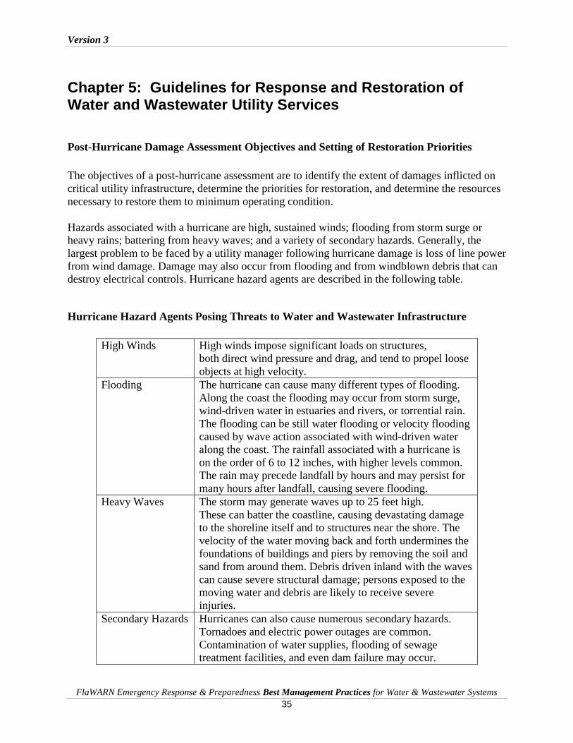
Version 3
FlaWARN Emergency Response & Preparedness Best Management Practices for Water & Wastewater Systems
35
Chapter 5: Guidelines for Response and Restoration of Water and Wastewater Utility Services
Post-Hurricane Damage Assessment Objectives and Setting of Restoration Priorities
The objectives of a post-hurricane assessment are to identify the extent of damages inflicted on
critical utility infrastructure, determine the priorities for restoration, and determine the resources
necessary to restore them to minimum operating condition.
Hazards associated with a hurricane are high, sustained winds; flooding from storm surge or
heavy rains; battering from heavy waves; and a variety of secondary hazards. Generally, the
largest problem to be faced by a utility manager following hurricane damage is loss of line power
from wind damage. Damage may also occur from flooding and from windblown debris that can
destroy electrical controls. Hurricane hazard agents are described in the following table.
Hurricane Hazard Agents Posing Threats to Water and Wastewater Infrastructure
High Winds High winds impose significant loads on structures,
both direct wind pressure and drag, and tend to propel loose
objects at high velocity.
Flooding The hurricane can cause many different types of flooding.
Along the coast the flooding may occur from storm surge,
wind-driven water in estuaries and rivers, or torrential rain.
The flooding can be still water flooding or velocity flooding
caused by wave action associated with wind-driven water
along the coast. The rainfall associated with a hurricane is
on the order of 6 to 12 inches, with higher levels common.
The rain may precede landfall by hours and may persist for
many hours after landfall, causing severe flooding.
Heavy Waves The storm may generate waves up to 25 feet high.
These can batter the coastline, causing devastating damage
to the shoreline itself and to structures near the shore. The
velocity of the water moving back and forth undermines the
foundations of buildings and piers by removing the soil and
sand from around them. Debris driven inland with the waves
can cause severe structural damage; persons exposed to the
moving water and debris are likely to receive severe
injuries.
Secondary Hazards Hurricanes can also cause numerous secondary hazards.
Tornadoes and electric power outages are common.
Contamination of water supplies, flooding of sewage
treatment facilities, and even dam failure may occur.

Version 3
FlaWARN Emergency Response & Preparedness Best Management Practices for Water & Wastewater Systems
36
Identification of Hurricane Landfall and Path of Storm (NOAA)
Information from local news networks can facilitate identifying hurricane landfall and the likely
path of the storm. Information can also be obtained from the web from the National Oceanic and
Atmospheric Administration (NOAA) their websites provide updates on the development of
storms, storm tracks, and more specific information on storms that reach hurricane status. These
sites are provided below:
http://www.nws.noaa.gov/om/hurricane/index.shtml
http://www.stormtracker.noaa.gov/
http://www.nhc.noaa.gov/
Pre-hurricane Preparation and Coordinated Utility Response (FlaWARN)
FlaWARN is Florida’s Water/Wastewater Agency Response network. FlaWARN’s mission is to
provide an effective communication mechanism that allows Florida’s water and wastewater
utilities to provide assistance to sister utilities that are in need.
There is no special requirement for membership in FlaWARN and utilities can register online at:
http://www.flawarn.org/.
FlaWARN works with various industry groups and public agencies linking the Florida water
community including:
The latest interactive models for security protocols to aid in continual risk assessment and
updating ERPs
A series of continually updated boilerplate public information and press release templates
tailored to meet the latest developments and provide immediate public response
Quarterly regional and annual statewide meetings to bring together both significant state
authorities and national interests, providing the best and latest insights to power the
agencies ongoing preparedness process. These meetings include workshops in utilizing
FlaWARN to the agencies best advantage.
Technologies to facilitate sharing of information among members
Outreach -- Through the existing UF/TREEO network and other cooperating entities,
FlaWARN will offer onsite emergency preparedness and related regulatory liaison
services to requesting agencies.
Reporting Hurricane Damages to DEP (Storm Tracker)
Storm Tracker is a web-based application that can be used by utilities to report the condition of
damaged utility facilities to DEP. Users are prompted to enter contact information and provide
facility reports on pre-prepared spreadsheets. The system currently tracks the condition of water

Version 3
FlaWARN Emergency Response & Preparedness Best Management Practices for Water & Wastewater Systems
37
and wastewater utilities that have service populations for water that are greater than 3,300 people
or wastewater systems that have treatment capacities of more than 100,000 GPD of wastewater.
The system allows DEP to maintain contact with system operators, update status conditions and
prioritize state assistance efforts. The system can be accessed via the web at:
http://tlhdwf2.dep.state.fl.us/stormtracker/facility.asp
To open the program, the user name is “florida” and the password is “storm” (please note: all
lower case).
Authorized State Emergency Management Agencies
The Florida Division of Emergency Management provides valuable information about how
Florida utilities can prepare for disasters and access State and Federal resources after a hurricane
strikes. The information can be accessed at:
http://www.floridadisaster.org/DEMinformation.htm
Priorities for the Restoration of Water and Wastewater Facilities
Restoration of water supply, transmission, and distribution receive precedence over other
activities. Drinking water is essential in allowing normal activities of the affected population to
resume. Contaminated drinking water can be rendered safe by boiling (sterilization) or by the
addition of chlorine or iodine (disinfection). Providing drinking water to the affected population,
even at low pressures, is essential in restoring normal lifestyle activities such as cooking and
bathing.
Once the water transmission and distribution system is restored, water treatment capability is the
next item of importance. If the water has been exposed to bacterial contamination, the following
guidelines are suggested:
Requirements for Sterilization of Bacterially Contaminated Water by Boiling
Sterilization Heat Source Vigorous boiling for a period
of one minute destroys cysts,
viruses, and bacteria
May be range, wood fire or microwave
oven. Extreme care should be used to
prevent accidental fires
Requirements for Disinfection of Bacterially Contaminated Water by Chemical Addition
Volume of Water Condition Number of Drops Chemical Disinfectant
Gallon Clean 20 Tincture of Iodine
Gallon Cloudy 40 Tincture of Iodine

Version 3
FlaWARN Emergency Response & Preparedness Best Management Practices for Water & Wastewater Systems
38
Gallon Clean 8 Chlorine Bleach
Gallon Cloudy 16 Chlorine Bleach
Tincture of Iodine is over the counter pharmaceutical quality.
Chlorine Bleach is unscented commercial laundry product at 5.25percent available
chlorine. Highly contaminated water should be filtered through cloth to remove any
suspended matter.
In a post-hurricane event, water transmission and distribution restoration should provide water at
any volume and pressure to a water customer. The utility should work from minimal service to
customers to its standard service pressure at a minimum pressure at 20 psi. The quality of water
obtained from a public water source can be more easily confirmed than from sources of unknown
origin.
As transmission and distribution service is restored, the next priority is to provide water to
critical installations. Restoration should then proceed to reestablish acceptable treatment levels to
remove any restrictions in water use. Once water transmission, distribution, and treatment have
been restored, wastewater restoration can then proceed. The following are recommended
priorities for restoration of water and wastewater service.
Priorities for Restoring Water and Wastewater Services to the General Populous
1. Restore water transmission and distribution capability to critical customers such as
hospitals shelters, emergency operations centers and special needs locations.
2. Restore water transmission and distribution capability to general population.
3. Restore water treatment capability.
4. Isolate and control leaks in water transmission and distribution piping.
5. Restore wastewater collection and transmission capability in areas where wastewater
contamination could threaten public drinking water supplies.
6. Restore wastewater collection and transmission capabilities in areas where wastewater
flow can result in public nuisance (flow into public roadways, private property, or water
courses).
7. Restore wastewater treatment capability.
Damage Response upon Hurricane Arrival
The term “hurricane” describes a severe tropical cyclone with sustained winds of 74 miles per
hour (mph) or greater.
The damages inflicted on utility infrastructure will generally be proportional to the intensity of
the hurricane measured by the Saffir-Simpson scale. The scale is a widely recognized, accepted
and practical tool that estimates the destructive forces associated with hurricanes. This scale
classifies hurricanes into five categories based on wind speed and describes the destructive
forces caused by wind, storm surge, and wave action for each category. The categories are listed
below.

Version 3
FlaWARN Emergency Response & Preparedness Best Management Practices for Water & Wastewater Systems
39
Saffir-Simpson Scale Hurricane Category and Sustained Wind Speed (mph)
Category 1 Hurricane:
Winds 74-95 mph (64-82 kt or 119-153 km/hr). Storm surge generally 4-5 feet above
normal. No real damage to building structures. Damage primarily to unanchored mobile
homes, shrubbery, and trees. Some damage to poorly constructed signs. Also, some
coastal road flooding and minor pier damage can occur.
Category 2 Hurricane:
Winds 96-110 mph (83-95 kt or 154-177 km/hr). Storm surge generally 6-8 feet above
normal. Some roofing material, door, and window damage to buildings may occur.
Considerable damage to shrubbery and trees with some trees blown down. Considerable
damage to mobile homes, poorly constructed signs, and piers. Coastal and low-lying
escape routes flood 2-4 hours before arrival of the hurricane center. Small craft in
unprotected anchorages break moorings.
Category 3 Hurricane:
Winds 111-130 mph (96-113 kt or 178-209 km/hr). Storm surge generally 9-12 feet
above normal. Some structural damage to small residences and utility buildings with
minor amount of curtainwall failures. Damage to shrubbery and trees with foliage blown
off trees and large trees blown down. Mobile homes and poorly constructed signs are
destroyed. Low-lying escape routes are cut by rising water 3-5 hours before arrival of the
center of the hurricane. Flooding near the coast destroys smaller structures with larger
structures damaged by battering from floating debris. Terrain continuously lower than 5
feet above mean sea level may be flooded inland 8 miles (13 km) or more. Evacuation of
low-lying residences within several blocks of the shoreline may be required.
Category 4 Hurricane:
Winds 131-155 mph (114-135 kt or 210-249 km/hr). Storm surge generally 13-18 feet
above normal. More extensive curtain wall failures with some complete roof structure
failures on small residences. Shrubs, trees, and all signs are blown down. Complete
destruction of mobile homes. Extensive damage to doors and windows. Low-lying escape
routes may be cut off by rising water 3-5 hours before arrival of the center of the
hurricane. Major damage to lower floors of structures near the shore. Terrain lower than
10 feet above sea level may be flooded requiring massive evacuation of residential areas
as far inland as 6 miles (10 km.
Category 5 Hurricane:

Version 3
FlaWARN Emergency Response & Preparedness Best Management Practices for Water & Wastewater Systems
40
Winds greater than 155 mph (135 kt or 249 km/hr). Storm surge generally greater than 18
feet above normal. Complete roof failure on many residences and industrial buildings.
Some complete building failures with small utility buildings blown over or away. All
shrubs, trees, and signs blown down. Complete destruction of mobile homes. Severe and
extensive window and door damage. Low-lying escape routes are cut off by rising water
3-5 hours before arrival of the center of the hurricane. Major damage to lower floors of
all structures located less than 15 feet above sea level and within 500 yards of the
shoreline. Massive evacuation of residential areas on low ground within 5-10 miles (8-16
km) of the shoreline may be required.
The hurricane season runs from the first of June until the end of November. Although the actual
landfall of a hurricane will typically produce the most damage, gale force winds and rain prior to
hurricane landfall and the sustained storm activity after the passage of a hurricane can produce
significant damage to and flooding of utility infrastructure. Typically, a hurricane will produce a
sustained storm event that may last for several days and bring excessive amounts of rain. The
time phases associated with a hurricane are:
Hurricane Readiness Requirements – Time to Arrival of Storm
Awareness 72 hours before the arrival of gale force winds (32-63 mph).
Stand-by 48 hours before the arrival of gale force winds. It is likely that a tropical storm
watch would be issued by the National Weather Service during this period.
Suspend all normal business activities.
Response 24 to 48 hours before arrival of gale force winds through termination of the
emergency. Hurricane watches and warnings will be issued by the National
Weather Service during this period.
Shelter 24 hours before landfall sustained gale force winds will exceed 40 MPH as
determined by the National Weather Service. All personnel should seek shelter
immediately.
As the hurricane approaches, utility infrastructure will begin to be impacted. Power failures will
begin to appear as trees are blown into overhead power lines. Utility crews will be dispatched to
begin emergency restoration procedures. Larger utilities will generally use SCADA equipment
that will give instantaneous operational status of critical water and wastewater facilities. Crews
will then be dispatched to respond to locations that indicate loss of power conditions. Response
activities will generally consist of maintaining water source capabilities at well fields or surface
water pumping stations, and setting up of pump-down routes for smaller lift stations and
placement of portable generators for larger lift stations. Larger lift stations with permanent
generators will have automatically started in some instances.
Water and Wastewater Treatment facilities may need to start permanent generators during this
period since power blips caused by the downed trees and limbs across overhead wires resulting

Version 3
FlaWARN Emergency Response & Preparedness Best Management Practices for Water & Wastewater Systems
41
from wind gusts can degrade power quality to the degree that it can damage plant electrical
equipment. Permanent generators at larger lift stations may also need to be started at this time.
As storm conditions worsen, winds will begin to approach gale force. When winds reach a
sustained velocity of 40 mph as determined by the National Weather Service, utility crews must
be ordered to discontinue activities and seek immediate shelter. Under these types of wind
conditions, falling trees and wind blown debris will jeopardize worker safety in the field and
vehicle travel is no longer safe. All utility repair and mitigation activities, no matter how
important, should cease at this point and workers should be ordered to seek shelter.

Version 3
FlaWARN Emergency Response & Preparedness Best Management Practices for Water & Wastewater Systems
42
Chapter 6: Conducting Post Hurricane and Tornado Assessments
Post Hurricane Employee Safety – Sustained Wind Speed
As the hurricane makes landfall and then passes, sustained tropical force winds will subside to
less than 40 mph sustained allowing damage assessment to begin. Communication infrastructure
during this period will likely be damaged and unreliable. Prearranged instructions for employee
reporting and field deployment of assessment crews consist of the following protocol:
Protocol for Contacting Employees for Post-Hurricane Damage Assessment
Instructions received directly from a supervisor via telephone landline
Instructions received directly from a supervisor via cell phone
Instructions received directly from a supervisor via mobile radio
Instructions received from a message delivered via local radio or TV station
Prearranged time period for reporting (generally 24 hours after landfall)
In a post-hurricane event for a Category 3 storm, generally about 25 percent of the normal
workforce will be unable to report immediately to work in the aftermath of a storm. In Category
4 and 5 storms, in some instances, as much as 75 percent of the workforce may be unable to
report immediately to work after the storm and this situation may extend for several days after
the storm. For this reason it is imperative that the utility build depth into its organization by
training additional employees in damage assessment techniques.
Types of Damage Assessments
Damage assessment consists of two types; Rapid Damage Assessment and a follow-up Detailed
Damage Assessment.
Rapid Damage Assessments
The purpose of the rapid damage assessment is to quickly develop a preliminary understanding
of the extent of damages to individual utility installations that prevent the facility equipment
from operating normally. The rapid damage assessment will determine both the extent of
electrical power damages and damages to facility equipment.
In most instances, the damages to utility structures will be limited to loss of power. In other
instances damages may be to overhead power drops or to electrical control equipment. Utility
personnel that perform damage assessments should be trained in recognizing specific types of

Version 3
FlaWARN Emergency Response & Preparedness Best Management Practices for Water & Wastewater Systems
43
problems. Forms can be very useful in obtaining needed information, but assessors should be
trained to include field notes. These field notes can be very informative and give the context in
which the information was collected. Since there are many variables that will not be captured on
a form, assessors should be trained to recognize and record pertinent and special conditions that
are observed while at the site. These variables, when documented, allow the restoration of a
facility to be better prioritized.
Assessors should also be instructed to record information that can be used to design response
efforts that can mitigate conditions or prevent additional damages to a facility or equipment. This
information should be recorded on the rapid assessment form. Drawings, diagrams, and pictures
should be provided in the event that they might be useful for later interpretation and to
facilitating the analysis of the collected information.
The following form is recommended for use by the rapid damage assessment team.

Version 3
FlaWARN Emergency Response & Preparedness Best Management Practices for Water & Wastewater Systems
44
Rapid Damage Assessment Form
Date: ________________ Time: ______________ Pictures Taken? Yes __ No __
Water Installation ___ Wastewater Installation ___ Treatment Facility ___
Plant Facility Name: ____________________________________________________
Address or Location: ____________________________________________________
Person Making Report: __________________________________________________
1. Power Supply Line Power Condition: Power is On ____ Power is Off ____
(if Line Power is On Skip to #2)
Are there visible damages to overhead lines? Yes __ No __
Are line fuses open? Yes __ No __
Are there trees or limbs visible on electrical lines? Yes __ No __ Is the service line to electrical cabinet damaged? Yes __ No __
2. Flooding Is the facility accessible? Yes __ No __ Is the facility under water? Yes __ No __
Is there evidence of inundation (high water marks)? Yes __ No __
3. Electrical Status Is there a generator on-site? Yes __ No __ Is generator operating? Comments: _________________________
Is the electrical panel damaged? Yes __ No __
Is SCADA equipment operable? Yes __ No __
Are there any breakers tripped inside panel? Yes __ No __
Number of pumps on-site ___, Are all operational? Yes __ No __ 4. Other Damages Are piping systems functioning? Yes __ No __
Is there evidence of spills or other reportable activity? Yes __ No __
5. Comments: For recording Comments, for your explanation of any Box checked
“Yes,” and for recording you Field Notes, use the back of this sheet.

Version 3
FlaWARN Emergency Response & Preparedness Best Management Practices for Water & Wastewater Systems
45
Rapid assessment teams will generally work in pairs as a safety precaution since field conditions
will continue to be unsafe due to flooding, downed trees and wires, rain and slippery pavement.
Facilities that have been inspected and found to pose threats or damages to the public, to other
employees or to private property should be reported immediately. These include downed electric
lines, broken water or wastewater mains, gas leaks, ruptured water service lines, or manholes
where covers are removed or from which sewage is seeping out in roadways or is flowing.
Those facilities that are not operational and affect the ability to properly treat drinking water, are
spilling over 1,000 gallons of wastewater, or are incapable of treating wastewater must be
reported to the State Emergency Warning Point at 850-320-0519. The DEP District and/or the
ACHD should be notified if the spill is less than 1,000 gallons.
Once a facility has received a rapid assessment inspection, it should be tagged to alert other
employees that the inspection has been completed.
Outside Assistance in Performing a Rapid Assessment
Generally the first step in determining resource needs is the performance of a rapid assessment
by the damaged utility. The damaged utility has insight into the facility requirements, their
locations and other pertinent information that will not be readily available to an outside assisting
agency.
However, in cases of catastrophic damage, the damaged utility may seek assistance from other
utilities and state and federal agencies. In these cases it is imperative that the damaged utility
provide employees who have utility information and can assist with locating and inspecting
damaged facilities.
All utilities are advised to prepare location maps of utility infrastructure, instructions on how to
find the facilities, the voltage, phase, FLA, number and rated horsepower of motors used at the
location. Also information should be provided on disconnects, pump-arounds, system by-pass
(in-pipe hydraulic surcharging) or any other pertinent information about the facility that can help
assisting agencies in restoring minimum operating levels.
Detailed Damage Assessment
Detailed damage assessments are initiated at the conclusion of the rapid damage assessment
period. The purpose of the detailed damage assessment is to prioritize system needs that provides
for a continuous improvement in operational status of equipment based on its critical need, in the
shortest amount of time possible at a reasonable expense to the affected utility.
A detailed damage assessment will typically begin about 24 hours after the rapid damage
assessment has been completed. The purpose of a detailed damage assessment is to locate and
identify specific critical locations where restoration can most effectively be provided. The
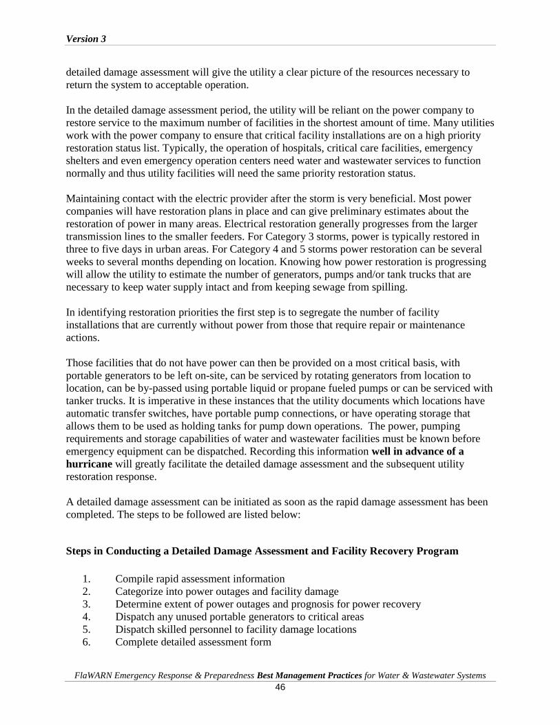
Version 3
FlaWARN Emergency Response & Preparedness Best Management Practices for Water & Wastewater Systems
46
detailed damage assessment will give the utility a clear picture of the resources necessary to
return the system to acceptable operation.
In the detailed damage assessment period, the utility will be reliant on the power company to
restore service to the maximum number of facilities in the shortest amount of time. Many utilities
work with the power company to ensure that critical facility installations are on a high priority
restoration status list. Typically, the operation of hospitals, critical care facilities, emergency
shelters and even emergency operation centers need water and wastewater services to function
normally and thus utility facilities will need the same priority restoration status.
Maintaining contact with the electric provider after the storm is very beneficial. Most power
companies will have restoration plans in place and can give preliminary estimates about the
restoration of power in many areas. Electrical restoration generally progresses from the larger
transmission lines to the smaller feeders. For Category 3 storms, power is typically restored in
three to five days in urban areas. For Category 4 and 5 storms power restoration can be several
weeks to several months depending on location. Knowing how power restoration is progressing
will allow the utility to estimate the number of generators, pumps and/or tank trucks that are
necessary to keep water supply intact and from keeping sewage from spilling.
In identifying restoration priorities the first step is to segregate the number of facility
installations that are currently without power from those that require repair or maintenance
actions.
Those facilities that do not have power can then be provided on a most critical basis, with
portable generators to be left on-site, can be serviced by rotating generators from location to
location, can be by-passed using portable liquid or propane fueled pumps or can be serviced with
tanker trucks. It is imperative in these instances that the utility documents which locations have
automatic transfer switches, have portable pump connections, or have operating storage that
allows them to be used as holding tanks for pump down operations. The power, pumping
requirements and storage capabilities of water and wastewater facilities must be known before
emergency equipment can be dispatched. Recording this information well in advance of a
hurricane will greatly facilitate the detailed damage assessment and the subsequent utility
restoration response.
A detailed damage assessment can be initiated as soon as the rapid damage assessment has been
completed. The steps to be followed are listed below:
Steps in Conducting a Detailed Damage Assessment and Facility Recovery Program
1. Compile rapid assessment information
2. Categorize into power outages and facility damage
3. Determine extent of power outages and prognosis for power recovery
4. Dispatch any unused portable generators to critical areas
5. Dispatch skilled personnel to facility damage locations
6. Complete detailed assessment form

Version 3
FlaWARN Emergency Response & Preparedness Best Management Practices for Water & Wastewater Systems
47
7. Develop status monitoring system (status board)
8. Prioritize response plan according to critical needs
9. Dispatch available in-house resources
10. Request outside assistance
The detailed damage assessment categories listed below will be helpful in determining priorities
and for quantifying requests for outside assistance. Generally, damage assessment reports will be
sent to the designated emergency manager and outside requests will go to FlaWARN at Carol
Hinton at: 352.392.9570 ext. 209 or Chris Roeder at: 352.392.9570 ext.203 or via the web at
FlaWARN.ORG. If damages are catastrophic FEMA assistance should be requested in addition
to assistance from FlaWARN.
Detailed Damage Assessment Classifications
Category Duration/Resolution Examples
Routine damage to
facilities
and/or power
outages in some
areas
Disruption can be
resolved within 24 hours.
Restoration is made
using in-house resources
Line breaks
Minor mechanical problems
Short term power outage
No threat to public health
Minor damage to
facilities
and/or Power
outages in most
areas
Disruption can be
resolved within 72 hours.
Restoration is made
using local contracted
service and in-house
resources.
Minor disruption in
treatment
Minor damage to power grid
Damage requiring
specialized equipment or
parts
Significant damage
to facilities and
significant damage
to power
infrastructure
Disruption can take up to
a week to resolve.
Restoration requires the
short-term use of outside
utility resources and
some assistance from
FEMA.
Major damage to utility
infrastructure
Loss of portions of power
grid
Multiple line breaks
Loss of supply pressure in
some areas of system
Catastrophic damage
to facilities and Loss
of power
infrastructure
Disruption can take
several weeks to months
to resolve. Restoration
requires significant and
long-term use of outside
utility resources and
assistance from FEMA.
Total loss of supply pressure
or treatment capability
Power grid severely
damaged
Significant mechanical,
electrical or contamination
problems

Version 3
FlaWARN Emergency Response & Preparedness Best Management Practices for Water & Wastewater Systems
48
Below is a detailed damage assessment form that may be used to assess the severity of damages
to utility facilities. When the repairs have been completed, the information should be submitted
to the supervisor including the tracking number.
Detailed Damage Assessment Form
Date: ________________ Time: ______________ Pictures Taken? Yes __ No __
Water Installation ___ Wastewater Installation ___ Treatment Facility ___
Plant Facility Name: ____________________________________________________
Address or Location: ____________________________________________________
Person Making Report: _____________________________ Title: ______________
Tracking Number: _____________________________
1. Type of damage to facility:
2. Resources needed for repairs:
Materials:
Equipment:
Labor:
3. Estimated time to repair facility:
4. Recommendations for mitigating problem or damages:
5. Comments: For recording Comments, and for recording Field Notes, please
use the back of this sheet.
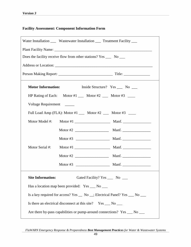
Version 3
FlaWARN Emergency Response & Preparedness Best Management Practices for Water & Wastewater Systems
49
Facility Assessment: Component Information Form
Water Installation ___ Wastewater Installation ___ Treatment Facility ___
Plant Facility Name: ____________________________________________________
Does the facility receive flow from other stations? Yes ___ No ___
Address or Location: ____________________________________________________
Person Making Report: _____________________________ Title: ______________
Motor Information: Inside Structure? Yes ___ No ___
HP Rating of Each: Motor #1 ___ Motor #2 ___ Motor #3 ____
Voltage Requirement _____
Full Load Amp (FLA): Motor #1 ___ Motor #2 ___ Motor #3 ____
Motor Model #: Motor #1 ___________________ Manf. _______________
Motor #2 __________________ Manf. _______________
Motor #3 __________________ Manf. _______________
Motor Serial #: Motor #1 ___________________ Manf. _______________
Motor #2 __________________ Manf. _______________
Motor #3 __________________ Manf. _______________
Site Information: Gated Facility? Yes ___ No ___
Has a location map been provided: Yes ___ No ___
Is a key required for access? Yes __ No __; Electrical Panel? Yes ___ No ___
Is there an electrical disconnect at this site? Yes ___ No ___
Are there by-pass capabilities or pump-around connections? Yes ___ No ___
Version 3
FlaWARN Emergency Response & Preparedness Best Management Practices for Water & Wastewater Systems
50
Tornado Response Assessment
Tornadoes produce a tremendous amount of very localized wind and are capable of completely
leveling water and wastewater facilities. Unlike hurricanes, tornado damages are extremely
localized thus businesses and facilities just a mile or less from the storms center will be fully
operational and thus response will not require the mobilized planning of a hurricane.
With a tornado the best source of information as to the locations of damages to will typically be
through the State Emergency Management network and the local news media. To obtain rapid
information on damages to small utility facilities it is best to contact local contract operations
companies who often manage several small utilities in local geographic areas. Circuit riders who
are assigned to these areas should maintain current cell phone numbers and contacts for contract
operations personnel.
Damages to utility structures damaged by hurricanes will be extensive. The Fujita scale (F-
Scale), or Fujita-Pearson scale, is the scale used for rating tornado intensity. It is based on the
damage tornadoes inflict on human-built structures and vegetation. The official Fujita scale
category was determined by meteorologists and engineers after examining damage, ground-swirl
patterns, radar tracking, eyewitness testimonies, media reports and damage imagery, as well as
photogrammetry and videogammetry if video was available. The scale below indicates the
corresponding estimated tornado wind speeds that are required to inflict the damages shown
below by the F rating.
F1 Corresponding tornado wind speed: 73-112 mph
F2 Corresponding tornado wind speed: 113-157 mph
F3 Corresponding tornado wind speed: 158-206 mph
F4 Corresponding tornado wind speed: 207-260 mph
F5 Corresponding tornado wind speed: 261-318 mph
Response to hurricane damage differs from hurricane response because local resources will be
adequate to respond to utility needs. It will be incumbent upon Florida Rural Water Association
personnel to coordinate resources quickly to put basic water and wastewater facilities back into
temporary operation as soon as possible.
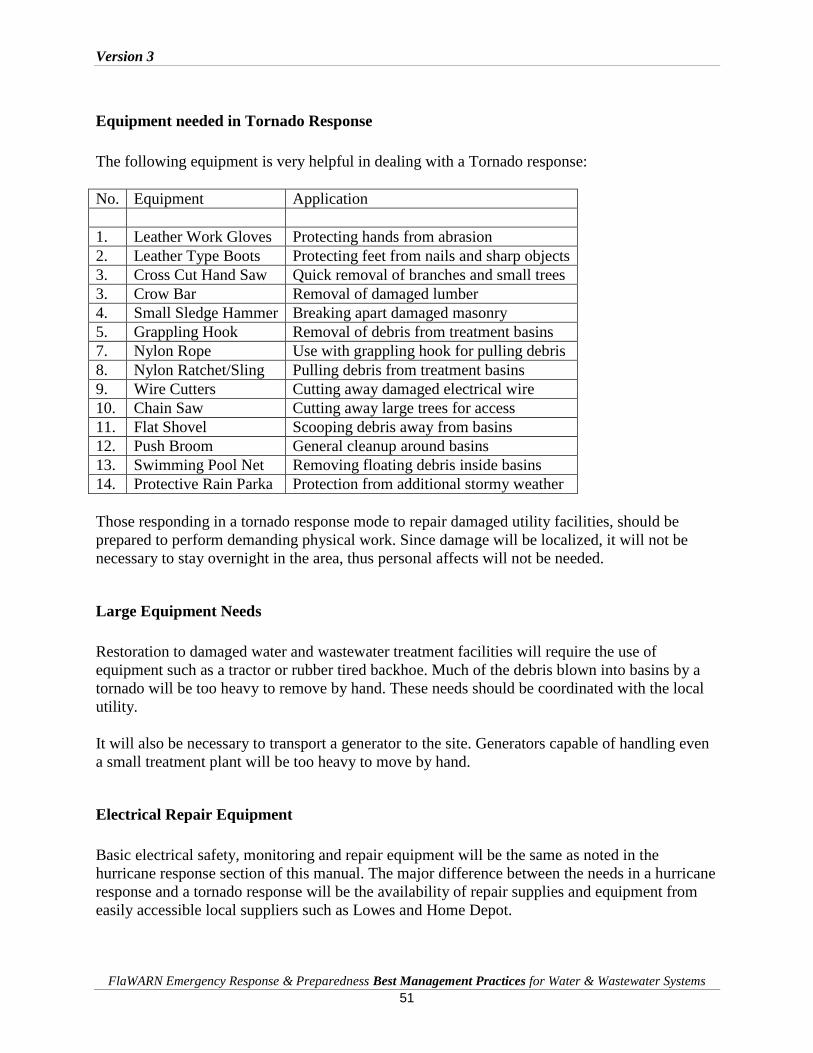
Version 3
FlaWARN Emergency Response & Preparedness Best Management Practices for Water & Wastewater Systems
51
Equipment needed in Tornado Response
The following equipment is very helpful in dealing with a Tornado response:
No. Equipment Application
1. Leather Work Gloves Protecting hands from abrasion
2. Leather Type Boots Protecting feet from nails and sharp objects
3. Cross Cut Hand Saw Quick removal of branches and small trees
3. Crow Bar Removal of damaged lumber
4. Small Sledge Hammer Breaking apart damaged masonry
5. Grappling Hook Removal of debris from treatment basins
7. Nylon Rope Use with grappling hook for pulling debris
8. Nylon Ratchet/Sling Pulling debris from treatment basins
9. Wire Cutters Cutting away damaged electrical wire
10. Chain Saw Cutting away large trees for access
11. Flat Shovel Scooping debris away from basins
12. Push Broom General cleanup around basins
13. Swimming Pool Net Removing floating debris inside basins
14. Protective Rain Parka Protection from additional stormy weather
Those responding in a tornado response mode to repair damaged utility facilities, should be
prepared to perform demanding physical work. Since damage will be localized, it will not be
necessary to stay overnight in the area, thus personal affects will not be needed.
Large Equipment Needs
Restoration to damaged water and wastewater treatment facilities will require the use of
equipment such as a tractor or rubber tired backhoe. Much of the debris blown into basins by a
tornado will be too heavy to remove by hand. These needs should be coordinated with the local
utility.
It will also be necessary to transport a generator to the site. Generators capable of handling even
a small treatment plant will be too heavy to move by hand.
Electrical Repair Equipment
Basic electrical safety, monitoring and repair equipment will be the same as noted in the
hurricane response section of this manual. The major difference between the needs in a hurricane
response and a tornado response will be the availability of repair supplies and equipment from
easily accessible local suppliers such as Lowes and Home Depot.
Version 3
FlaWARN Emergency Response & Preparedness Best Management Practices for Water & Wastewater Systems
52
Chapter 7: Contamination in Restoration of Utility Services
Public Health Concerns
Addressing public health issues is the first concern when entering the disaster area. The
restoration of water service is always the highest priority. Establishing water pressure will help
in fire fighting and clean up efforts and that is important but making the water potable is
paramount and urgent. Wells need to be energized and then need to be cleaned up. In most
cases, super-chlorinating is necessary with flushing to obtain a reasonable residual. Maintaining
pressure in the distribution system is necessary so that leaks can be found and repaired or
isolated. Rescinding boil water advisories is important and knowledge of local regulations is
necessary.
DEP Protocols for Contaminated Drinking Water
The following protocols are intended to guide and clarify requirements for public water systems
(PWS) that have been contaminated or have the potential to become contaminated following a
severe storm event. These guidelines are intended to enhance communication and coordination
between the impacted water system, your customers, your regulatory food agency (DBPR, DOH
or DACS), the county health department, and the DEP District Office. Effective communication
between entities and consistency of application for these guidelines is critical for public health
protection during emergencies.
Precautionary Boil Water Notice
When an emergency event occurs that warrants a precautionary boil water notice (PBWN), it is
vital that the public water system first notifies its water regulatory agency (DEP District Office
or Approved County Health Department) about the situation as is required under Rules 62-
555.350(10)(b) and 62-560.410(1)(a)1 and (9), Florida Administrative Code (FAC). When the
water system is regulated by DEP, they request that the county health department (CHD) is also
notified about an event requiring a PBWN. By rule, it is the water system owner’s responsibility
to provide public notification to its affected consumers; however the approved CHD and DEP
must be consulted and they will initiate customer notification (a PBWN) if the PWS cannot or
will not do so. If food is prepared, the regulatory food agency (DACS, DOH, or DBPR) also
requires notification if there is an emergency. Following the issuance of a PBWN,
communication and coordination must continue.
Sample public notices are provided in the Appendix.

Version 3
FlaWARN Emergency Response & Preparedness Best Management Practices for Water & Wastewater Systems
53
Power Outages and System Malfunction Requirements
In the event of a power outage or system malfunction that results in zero pressure in the water
system, the following are needed:
Call, and email or fax the PBWN to the local DEP District Office, or Approved County
Health Department
Call, and email or fax the PBWN to the county health department
Post the PBWN at drinking water outlets in the building(s)
The PBWN must state the name of the PWS, the time and date of issuance, what
happened, what corrective measures are being taken, what the public should do, and other
appropriate information required in Rule 62-560.410(5), FAC
Undertake those corrective actions to the water system, restore pressure and maintain
disinfectant residual, perform flushing as needed, and test for coliform bacteria as
prescribed by the agency overseeing the system
After lab results prove satisfactory, send a copy of the lab results to the applicable
regulatory agency, obtain their approval, and rescind the PBWN if locally issued; if
issued by DEP or the CHD they will rescind
Procedures for Rescinding Boil Water Notices
The rules for lifting boil water notices vary from state to state. If there is time prior to deploying,
research the notices before going into another state or ask the FlaWARN staff to assist. Getting
chlorinators and chlorine injection pumps re-piped and running needs to be a concerted effort.
Finding the proper equipment, tubing, and fittings can be challenging.
Procedures for Collection of Water Samples
When corrective actions are completed, water samples must be collected and tested to validate
the microbiological safety of drinking water provided to consumers. The water system owner is
responsible to assure they are collected and tested. For a non-community system, two water
samples collected at locations where water is available for consumption (taps or fixtures) is
adequate to assess the microbiological safety of the system. Ensure that the water samples are
collected in a sanitary manner and chilled with ice during storage before delivery to a DOH
certified laboratory for analyses. The PBWN Guidance requires at least one day of satisfactory
samples before rescinding (lifting) the notice. Laboratory test results of the samples must be
provided to the regulatory water agency prior to rescinding the notice. Request the lab to send
those results directly to the regulatory office. If there is a water main break, two consecutive days
of samples are required to be satisfactory. If any sample is found to contain coliform bacteria,
the boil water notice must be sustained, and two consecutive days of satisfactory samples are
required before the water is deemed safe to drink. Whichever entity (the Water System, DEP, or
CHD) issues the PBWN, must also properly rescind it after the above task list is completed.

Version 3
FlaWARN Emergency Response & Preparedness Best Management Practices for Water & Wastewater Systems
54
DEP approved Standard Operating Procedures (SOP’s) for sampling and analysis can be found
at: http://www.dep.state.fl.us/labs/qa/sops.htm.
Contacts for Additional Guidance
If there are any questions regarding the information in this letter, please contact either your DEP
District Office drinking water program staff or Approved County Health Department drinking
water section. The rule referenced Precautionary Boil Water Notice Guidance with notice and
rescission examples are online at: http://www.doh.state.fl.us/environment/water/manual/boil.htm
Prioritizing to Re-establish Water Service and Minimize Contamination
The priority for an assisting agency will be to restore drinking water service to a safe and reliable
condition. However, inoperative lift stations and wastewater facilities will threaten drinking
water sources if left inoperable for long. Since resources will be limited, it is imperative that the
assisting agency work with the receiving agency to establish restoration priorities. The list below
is a suggested priority restoration schedule. However it should be adapted to the specific
conditions at the location based on the impacts to public health.
Suggested Priorities for Restoring Service in Disaster Areas
1. Water – Wells, Supply & High Service Pumps
2. Lift Stations – Get wastewater out of the streets & homes
3. Water Quality – Disinfection if deficient
4. Wastewater Treatments – Operational
5. Water Pressure & Leaks – Locating / Isolating Leaks, Storage Issues

Version 3
FlaWARN Emergency Response & Preparedness Best Management Practices for Water & Wastewater Systems
55
Chapter 8: Procedures for Response and Receiving Agencies for Restoration Activities
Preparation Procedures for Receiving Agencies
Being prepared to receive assistance in the wake of a storm is just as important as responding to
someone in need. The receiving agency can do much to make the recovery go quickly and
efficiently. Being ready when the responder utilities show up and putting them to work will
include providing system information and in some cases facilities for their use.
Preparation of System Maps
System maps showing locations of key facilities will be needed. Some receiving utilities are
prepared to provide CD’s of their utility Geographic Information System (GIS). Other utilities
are providing complete hard copy maps and data sheets. There is also some discussion of
placing utility GIS on the World Wide Web by other utilities. Global Positional System (GPS)
coordinates can be vital since road signs tend to disappear and the landscape can drastically
change. Street addresses for each facility are necessary since many map software packages
operate from street addresses and have proved very helpful in navigating damaged areas. Data
for water wells, water treatment facilities, pumping stations, wastewater treatment facilities, and
lift stations should be provided. Information that would be helpful includes pump types and
motor specifications, treatment processes, and flow schematics. Valve maps with locations
shown can be important since many of these tend to get covered. Identifying make and model of
generator receptacles can help responding teams prepare. Maps and system information should
be stored outside surge areas and in waterproof containers if possible. If it’s necessary to
provide responders direct access to data stored on the server of the receiving utilities, it is
advisable to place the information in a separate file and protect it with a password for use by the
responding utilities.
Providing Shelter and Sleeping Arrangements
Providing shelter and sleeping quarters or arrangements will be very helpful. Responding
utilities are expected arrive self-sufficient and ready for any conditions except for a place to
sleep and shower out of the weather. Some utilities set up to feed responding workers. Some are
able to provide cots but air mattresses seem to be a quick and easy way to provide a decent place
to sleep. An extended stay by a crew will necessitate laundry facilities. The responding utility
workers will arrive prepared to work 12 - 16+ hour days and that must be factored into their
accommodations.

Version 3
FlaWARN Emergency Response & Preparedness Best Management Practices for Water & Wastewater Systems
56
Security and Storage of Service Vehicles and Equipment
A place for the trucks and equipment must be found so that security is not a concern. Most
crews will want to be near their equipment and other belongings. Round the clock access at the
secured facility must be available if at all possible.
Identifying Work Task for Responder Agency
Be prepared upon the arrival of the responding crews to provide them assignments immediately.
Have a map highlighted with the system that needs coverage as well as specific locations and
tasks itemized that can be handed out. If at all possible, do not have the crews wait to go to
work. This means that priorities need to be understood and be ready to put into action. The
receiving utility may not know in advance the number and capabilities of responding crews so
they must be ready to deal with what assistance arrives. In the FlaWARN experience in
Mississippi, it was found that no preparation had been done for receiving assistance. In most
cases, utilities needing aid had no staff available to assist and no maps to disburse. This makes
the task or providing aid much more difficult generally although, the crews that arrive will be
able to handle even that situation.
Identification of Special Receiving Agency Safety Requirements
Before the dispatch of responding crews, they need to be made aware of any potential safety
issues and should be given the keys to control panels, motor control centers, and hatches.
Written lockout/tag-out documents are helpful. Knowing disinfection processes will be vital
although crews will be prepared to identify and handle just about any disinfection process.
Providing Points of Contact to Responder Agency
Provide responding crews with points of contact with the utility. The points of contact should be
readily available at all times. If there are open accounts for materials and supplies and it is
cleared for the responding crews to use them, have the appropriate purchase order numbers or
identifying information available is necessary.
Curfews and Checkpoint Considerations
If crews arrive after curfew, please make arrangements at the necessary checkpoints to allow
them access or arrange to meet and escort them to the facility. Security credentials, that include a
picture ID from your utility, will facilitate travel through checkpoints. SERT badges issued
through the Florida Department of Emergency Management are necessary to travel through
restricted sites and for accessing county EOC command centers.

Version 3
FlaWARN Emergency Response & Preparedness Best Management Practices for Water & Wastewater Systems
57
Equipment Operation Qualification Requirements
If only equipment is being provided by the responding utility, then the receiving utility must be
prepared and qualified to use it properly. In this situation it is important to always treat
equipment as your own and to return it to the responding utility in like or better condition. This
is the good neighbor policy and at the heart of mutual aid. Additional information and guidelines
have been provided in other sections of this document.
Proper Assessment and Prioritization of Receiving System Requests
While making physical arrangements, the receiving utility must also be cognizant of the
incoming requests for assistance. It is unlikely that enough people and equipment will be
available to handle all requests immediately; therefore these resources must be apportioned so
that the greatest good is done for the greatest number. Prioritize your needs as soon as
assessments are made. Here are some non-optimal requests that have been experienced:
1. Some requests have been general in nature. Such as: “all lift stations are down and I
need every available vacuum truck.” More specificity needs to be provided in the
request.
2. Requests exceed reasonability standards. Such as: I have 167 lift stations down and I
need 167 generators.
3. Requesting equipment even though your own is not being fully utilized just in case
something else happens.
4. Requesting assistance based on field reports. These requests can be unreliable and can be
very outdated. The most accurate information will be obtained from utility field
assessments using the forms provided in this document.
It is important that the receiving utility points of contact get out in the field to understand the
situations and be able to relay these in a timely manner that gets assistance on site and prepared
to work quickly and efficiently.
As a receiving utility, please keep in mind that many other utilities in the area are in the same
situation. Responding utilities will arrive to help get the system in some degree of service. They
are not there to help return the facility to normal operations. Construction and longer term
rebuilding activities are the responsibility of the host utility. Being able to efficiently utilize
assistance when it arrives not only helps the utility but it helps the community.
Consideration in the Selection of Responding Agency Team Members
Responsibility for selecting response team members after a disaster can be difficult due to the
long list of volunteers. Finding the right people out of that list will be an exercise in
management.

Version 3
FlaWARN Emergency Response & Preparedness Best Management Practices for Water & Wastewater Systems
58
Desirable Characteristics for Response Team Members
Following are some qualities team members should exhibit.
The right attitude, a positive attitude and a history free from complaining
A proven ability to work together in a team environment
Willingness to “rough it” for many days
Confidence they are capable of handling any situation
Ability to control their temper and their emotions
A proven record of being able to work under stress
A strong work ethic and be willing to take on any task whether in or outside their
specialty
The team members should be in reasonably good health and have an up-to-date inoculation
record. While working long hours they must be able to remain alert at all times in all conditions.
Team members will be expected to look after each other and care for their equipment. Needless
to say, they should be experienced with water and wastewater work and have the ability to work
independently. Experience with past restoration projects will be that much more valuable on a
new assignment. The desire to do a good job at all times under any condition is important while
not letting poor working conditions or lousy weather be an impediment. Most importantly, their
attitude must be spiced with a heavy dose of altruism.
Management and Supervision of Response Team Members
An experienced system manager should accompany the crews if possible. This manager can be
the team leader and be well versed in all aspects of utility operation. Crews can go to work
immediately upon arrival while the manager is doing a more complete assessment of the overall
situation. The manager can be the buffer between the assisting crews and the receiving utility
managers and crews until a rapport is established or they can establish an overall work plan. In
Mississippi, hostility to responding utilities was a common first reaction. An experienced
manager can overcome this initial hostility and gain the trust of the receiving utility. As more
and more states enter into mutual aid agreements, accepting help will become easier and more
common.
Desirable Licenses and Training for Response Team Members
Credentials for team members include:
CDL’s with endorsements
Confined space entry training and trench safety training
First aid training including CPR and defibrillator use
Hazmat training
Use of personal protective equipment including SCBA
Lockout/tag out training and electrical safety training
Version 3
FlaWARN Emergency Response & Preparedness Best Management Practices for Water & Wastewater Systems
59
Heavy equipment certification
Fire extinguisher training
Training in the use of Power Operated Equipment including chain saws
Skills needed may vary but usually the more experienced personnel should be first in line to go
no matter their specialty. Some of the skills needed include:
Master Electricians
Electrical technicians
Instrumentation technicians
Heavy equipment operators
Equipment maintenance staff
Plant and station operators
Distribution and collection technicians
General laborers
Mechanic, skilled in diesel, automotive, heavy equipment and generators
Procurement specialist
Since it will be impossible to equip a work team with individual specialists, it is best to choose
personnel that have knowledge of these work skills and are self-motivated to provide assistance
in supporting the response effort wherever and to whomever it may be needed.
Consideration in the Duration of Restoration Work Assignments
Teams should be planned for 7 - 10 day rotations with overlap of at least one day when the relief
crew arrives so knowledge can be transferred. Some team members will be reluctant to rotate
out at all and the manager must make a determination if that will lead to harm in any way.
Observing Responder Agency Work Rules and Union Agreements
Before dispatching crews, union agreements and work rules must be clarified and modified for
any special conditions. Compensation issues must be addressed. Reimbursements for any
personal items brought along for benefit of the team should be clarified. Some team members
may want to bring travel trailers or RV’s to assist with accommodations and payment for these
must be decided prior to deployment. Crews must understand that they are going to a scene of
human misery, shock and loss of focus due to the overwhelming job ahead. Crewmembers must
be able to effectively carry out their mission in this environment. The emotional preparation
must not be neglected. The crews must understand that they are not there to hinder, they are
there to help and keep in mind that the receiving utility does not belong to them and they are not
in charge of the recovery. Their assignments will come from the utility operator. In actuality,
crews may find that they are asked or welcomed to taking over all aspects of a recovery but
gaining the trust of the receiving utility must happen first.

Version 3
FlaWARN Emergency Response & Preparedness Best Management Practices for Water & Wastewater Systems
60
Chapter 9: Organizing Work for First Responders
Triage Mission of First Responder
The mission of the first responder is to restore water and wastewater facilities to operating
conditions that provide adequate service levels to the population affected. It is not the mission of
first responders to make permanent repairs to equipment or initiate long-term corrective actions.
First responders should be able to maintain their own existence for a period of ten days; this
includes water, food, bedding, and personal supplies, including their own medicines.
Establishing an Incident Command Operations Center
Because responder restoration activities many times involve personnel from multi-agencies,
establishment of a coordinated management structure should be the first item of business for the
first responder.
The Incident Command management structure is very effective in situations where many
different agencies will be involved with the restoration activities. The five management functions
shown below are the foundation of the Incident Command structure and can be used effectively
by a first responder upon arrival. An Incident Command organizational chart is shown below:
Incident Command sets incident objectives, strategies and priorities and has overall
responsibility for managing field operations. The major function and responsibilities for each
personnel assignment are shown on the next page:
Unified
Command
Safety
Liaison
Information
Operations Planning Logistics Finance
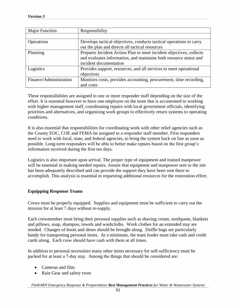
Version 3
FlaWARN Emergency Response & Preparedness Best Management Practices for Water & Wastewater Systems
61
Major Function Responsibility
Operations Develops tactical objectives, conducts tactical operations to carry
out the plan and directs all tactical resources
Planning Prepares Incident Action Plan to meet incident objectives, collects
and evaluates information, and maintains both resource status and
incident documentation
Logistics Provides support, resources, and all services to meet operational
objectives
Finance/Administration Monitors costs, provides accounting, procurement, time recording,
and costs
These responsibilities are assigned to one or more responder staff depending on the size of the
effort. It is essential however to have one employee on the team that is accustomed to working
with higher management staff, coordinating repairs with local government officials, identifying
priorities and alternatives, and organizing work groups to effectively return systems to operating
conditions.
It is also essential that responsibilities for coordinating work with other relief agencies such as
the County EOC, COE and FEMA be assigned to a responder staff member. First responders
need to work with local, state, and federal agencies, to bring the system back on line as soon as
possible. Long-term responders will be able to better make repairs based on the first group’s
information received during the first ten days.
Logistics is also important upon arrival. The proper type of equipment and trained manpower
will be essential in making needed repairs. Assure that equipment and manpower sent to the site
has been adequately described and can provide the support they have been sent there to
accomplish. This analysis is essential in requesting additional resources for the restoration effort.
Equipping Response Teams
Crews must be properly equipped. Supplies and equipment must be sufficient to carry out the
mission for at least 7 days without re-supply.
Each crewmember must bring their personal supplies such as shaving cream, toothpaste, blankets
and pillows, soap, shampoo, towels and washcloths. Work clothes for an extended stay are
needed. Changes of boots and shoes should be brought along. Duffle bags are particularly
handy for transporting personal items. At a minimum, the team leader must take cash and credit
cards along. Each crew should have cash with them at all times.
In addition to personal necessities many other items necessary for self-sufficiency must be
packed for at least a 7-day stay. Among the things that should be considered are:
Cameras and film
Rain Gear and safety vests

Version 3
FlaWARN Emergency Response & Preparedness Best Management Practices for Water & Wastewater Systems
62
Watches and alarms clocks
Sewing kit
Spare batteries for all battery operated equipment
Flashlights
Aspirin, antiseptics, antacids, bandages, gauze pads
Paper towels and wet wipes
Eating utensils
Reading material
Water bottles and day packs
Sun screen and insect repellent
Pen, pencil, notepaper
While it is difficult to ascertain the exact work to be done based on anticipated damage,
experience has shown that in the event of a major hurricane the initial damage assessment should
read – “everyone needs everything.” Therefore take the equipment that will be best utilized.
Included in this may be:
Generators
Bypass pumps
Service trucks
Excavation equipment
Diesel fuel tanks, either truck mounted or skid mounted
Miscellaneous repair parts and equipment such as pipe, fittings, and electrical parts
The tools and supplies needed to perform repairs may cover a large range since precise damage
cannot be ascertained at the time of deployment but the following have been items that have
proven useful:
GPS and Mapping software with laptops or handhelds
Shovels
Chainsaws
Nighttime project lighting
Wrenches, socket sets, pliers
Valve wrenches and extensions
Barrel pumps, either electric powered or manual
Volt meters
Amp meters
Insulated screwdrivers
“Hot gloves”
Wire stripper
Hacksaw
Electrical lugs and various wire sizes for short splices
Electrical tape and wire connectors
Pipe repair clamps

Version 3
FlaWARN Emergency Response & Preparedness Best Management Practices for Water & Wastewater Systems
63
Small single phase generators
Chlorine tablets (these were needed everywhere in Mississippi)
Spare chlorinator and chlorine injection pump
Bolt cutters
Crews will be going into areas for which there are no supply outlets and no services of any kind.
Being properly equipped becomes that much more important. It is impossible to predict the
specifics needed to affect a recovery so being stocked for the broadest range of circumstances is
very important.
Coordination of First Responders with FlaWARN
Each City, County, or Authority has an Emergency Operations Center or staging area that should
have employees designated as the FlaWARN contact point for the First Responders Team that
has traveled to the location of the emergency. Coordinating with these centers will be important
since it is likely that new work tasks will be added as progress is made.
Setting Operational Priorities for First Responders
Addressing public health issues should be the first concern when entering the disaster area. The
restoration of water service is always the first concern. In most cases, the loss of power will
dictate the installation of power generators. Establishing water pressure will help in fire fighting
and clean up efforts and that is important but making the water potable is paramount and urgent.
Wells need to be energized and then need to be cleaned up. In most cases, super-chlorinating is
necessary with flushing to obtain a reasonable residual. Some pressure in the distribution system
is necessary so that leaks can be ascertained and repaired or isolated. Rescinding boil water
advisories is important and knowledge of local regulations in this arena is necessary. The rules
for lifting boil water notices are not the same from state to state. Getting chlorinators and
chlorine injection pumps repiped and running needs to be a concentrated effort. Finding the
equipment, tubing, and fittings can be challenging.
Environmental issues such as overflowing lift stations need to be addressed next. After concern
for medical facilities, operations centers and shelters, lift stations will be the next priority for
restoration. In some cases addressing lift station contamination potential can prioritize these.
Procedures for performing this analysis are provided in another section. An overflowing lift
station will contaminate water supplies, disrupt traffic and can impede the operation of critical
government and medical facilities. Wastewater treatment plant issues should be addressed
quickly since without their operation, it may be difficult to put upstream lift stations in service.
Wastewater treatment plant issues should be addressed quickly since without their operation, it
may be difficult to put lift stations in service. Some level of service needs to be provided to
wastewater treatment facilities. If at least flow cannot be established through the plant, it will
result in “solids on the ground” at the plant site. During Katrina, many plants in Mississippi
were inundated. Control panels and motor control centers were rendered inoperable. Clarifier

Version 3
FlaWARN Emergency Response & Preparedness Best Management Practices for Water & Wastewater Systems
64
drive motors and aeration equipment was damaged and inoperable. All these had to be cleaned,
dried, and/or rebuilt or replaced. In one case in Mississippi, one vessel in the plant was able to
be operated at a low treatment level before discharging to surface waters but it did enable lift
stations to discharge and prevent sewage from spilling on the ground in populated areas.
Environmental issues such as overflowing lift stations need to be addressed next. In some cases
going after stations near population concentrations first can prioritize these. An overflowing lift
station at the Hancock County Medical Center in Mississippi after Katrina became a great
priority. A heroic effort to stop this hazard was successfully performed.
The largest issue getting lift stations in service is getting power to them. In most cases the
physical damage is not great so getting hooked to a generator is the main issue. In Florida,
generator receptacles are installed on most lift stations; however, there is no standardization on
receptacles so finding a male to female match may involve luck. Direct connection to the control
panel terminal posts should be contemplated and may be the only way to get connected. Only
experienced electricians or electrical/lift station technicians should be involved in this activity.
Entire control panels may be destroyed in which case a skeleton set-up for connection to pump
motors must be rigged. If grid power is available at the time a more extensive control panel
needs to be built and installed. Scavenging parts and pieces from other locations may have to be
done in order to rebuild or build a control panel. Extreme care should be employed when
working on electrical equipment since grid power can be re-established without warning.
Damage Assessment
Information about the conditions of water and wastewater facilities in a severely damaged area
may be sketchy or non-existent. It is unlikely that enough people and equipment will be available
to handle all requests immediately; therefore these resources must be apportioned so that the
greatest good is done for the greatest number. Here are some non-optimal requests that should
be expected:
Non-Optimal Requests from Devastated Areas
1. Non-Specific Information: Example; “all lift stations are down and I need every
available vacuum truck.” More specificity needs to be provided in the request.
2. Non-Reasonable Equipment Requests: Example: “I have 167 lift stations down
and I need 167 generators.”
3. Requests for Standby or Redundant Equipment: Example: “ I need additional
generators for those that will fail.”
4. Requests for Assistance based on Outdated Field Reports. Example: “All systems
are completely down and not repairable.”
These types of requests will impede restoration efforts and it is incumbent upon the Responder to
obtain reliable, specific, substantiated, field information.

Version 3
FlaWARN Emergency Response & Preparedness Best Management Practices for Water & Wastewater Systems
65
It is important that the receiving utility points of contact get out in the field to understand the
situations and be able to relay these in a fashion that gets assistance on site and prepared to work
quickly and efficiently.
Damage Assessment should proceed in the following manner:
Damage Assessment for First Responders
1. Send out a team to determine the number of leaks within the system and the location of
the line. Evaluate the impact of the spill based on the environmental surroundings.
2. Evaluate the damage to the facilities in the community and prioritize repair of
the facilities with consideration to flow, customers and emergency services located in the
same proximity.
3. Report the information to the ICC. First responders should also be equipped with a
satellite phone to be able to have communications if none are available.
Perform Damage Assessments on Individual Lift Stations
1. Have Lift Station maps with G.I.S. locations available.
2. Compile list of Lift Station priorities for power providers that will require power so that
there are fewer back-ups to hospitals, medical offices, food stores and shelters to limit
impacts on the community.
3. List of stations that have are equipped with emergency power but will require a re-fueling
schedule. Determine that roads to stations are accessible for fuel trucks, and that you’ve
made arrangements for with the fuel depot.
4. Develop schedules for staff working 12-hour shifts with breaks for food and rest.
5. Develop a schedule for pumping stations down that do not have power but would have an
impact on the priority list created in item b.
6. Develop an emergency center where staff can bring back work orders and cost factors for
personnel in the emergency center to calculate and transpose to FEMA reports and
records
7. Develop and practice good safety procedures with staff that are being sent as first
responders relating to electrical issues, first aid, and respiratory issues.
Perform Damage Assessments on Wastewater Treatment Plants
1. Complete damage assessment of facilities to determine priorities for
repairs.
2. Establish that emergency power is available and on-line if or when necessary.
3. Develop and schedule re-fueling for emergency generators based upon loads and hourly
fuel consumption, along with storage capacity.
4. Institute modified personnel shift rotations based upon Emergency Response Plan.
5. Exercise any unit by passes due to extreme abnormal flows.
6. Institute disinfection dosing rates due to conditions of abnormal flow, consider higher
long-term dosing rates and make plans for chlorine deliverers.

Version 3
FlaWARN Emergency Response & Preparedness Best Management Practices for Water & Wastewater Systems
66
7. Make sure that you have good supervisors with each crew you send (water, wastewater,
lift stations, etc.) due to the locals not sure of what really needs to be accomplished.
FEMA Work Documentation Requirements
Financial recovery is an essential aspect in any restoration effort. The key to successful financial
recovery when providing aid to other communities is consists of three items:
1. Documentation
2. Communication
3. Follow-up
The following are guidelines for documenting responder restoration work activities:
Documenting Restoration Work Activities
1. Establish authorized contacts in impacted area
a. Have at least two (2) contacts in the impacted area that can assist with directing
work crews in the relief effort
2. Keep a detailed daily log of assigned recovery activities, for example:
a. Type of vehicle used and miles logged
b. Type of work assigned and completed (include personnel assigned to effort)
c. Type of equipment used and/or loaned
d. Give a brief description of work performed (i.e. 6” water line repaired). Be specific
as possible; identify street name, address, intersection etc.
e. Log hours worked for both regular-time and overtime
f. Log meals, lodging arrangements, and other required items purchased
3. Use digital cameras, PDAs, laptops to facilitate detailing recovery effort
a. Most PDAs have the ability to take digital photo and act as a recorder. Use
technology to capture “before and after” pictures.
b. If necessary, use administrative personnel to dictate front-line work over the
phone to get a good coherent log of events and recovery effort.
Version 3
FlaWARN Emergency Response & Preparedness Best Management Practices for Water & Wastewater Systems
67
4. Retain all receipts
a. When possible use purchase or credit cards
b. All cash advances must have receipts to be reimbursed
c. Have a debriefing process once employees return from relief effort
d. Have employees turn-in logs, receipts, photos, recovery documentation within
twenty-four (24) hours of their return
5. Scan all recovery documents submitted for reimbursement
6. Establish contact(s) for the reimbursement and follow-up process
Labor costs are typically the bulk of the reimbursement request so it is important that you
maintain records to justify all labor charges and benefit rates. It is equally important that those
responsible for billing be familiar with and updated on FEMA reimbursement rates that are
subject to change.
Standard reporting forms for FEMA documentation and reimbursement are very helpful and
have been developed and are available through FlaWARN. Sample forms are found in the
Appendix.
FEMA Schedule of Equipment Rates
FEMA maintains a schedule of allowable rates for both labor and equipment for work performed
in restoration efforts. This Schedule is periodically updated. It is recommended that responders
and contractors obtain a current copy of the schedule. It can be down loaded from the FEMA
web site by searching: FEMA Schedule of Equipment Rates or at:
http://www.escambia.k12.fl.us/eert/fema/Equipment.
Organizing Emergency Responder Work
An emergency responder, team leader or situation leader must give careful consideration to
where to base response efforts. This is commonly referred to as a “staging area”. The staging
area will be the base of operations. It should help protect equipment from theft and vandalism,
facilitate access to work locations, and provide a place for organizing response efforts. It may
also provide a location for personnel accommodations such as eating, sleeping and personal
security for crews.

Version 3
FlaWARN Emergency Response & Preparedness Best Management Practices for Water & Wastewater Systems
68
Selection of a staging area will depend on how the response is organized. An organized
FlaWARN or FRWA effort may include a secure utility staging area for equipment in a
centralized area close to the damage work area. In many cases sleeping arrangements may be
located away from the staging site.
Many responders will be working out of a variety of vehicles. These may include standard or
extra duty pickup trucks; lift vehicles, tractor-trailer vehicles, etc. Remember that any response
effort must first have a centralized location to house equipment and dispatch it to the work areas.
Some equipment may serve multi-purpose use for transporting fuel, materials and employees to
job sites. Keeping equipment in one location is highly beneficial.
First responders may be tasked with locating an area to stage equipment and work crews.
Typically this begins by making telephone calls to response coordinators such as FlaWARN or
FRWA. Sometimes calling damaged utilities directly may be more effective. Communication
may include email exchanges and preliminary assessment meetings to determine types of
equipment and personnel needed in the response efforts and what responsibilities must be
covered. There may not be any communications near the impact area due to the loss of power
and phone service.
It is recommended that the response effort start as early as possible after a storm hits. First,
determine the locations where assistance may be needed. Remember that hurricanes are
unpredictable and severe damage can occur several hundred miles from landfall. Make sure that
response organizations know that you are available to assist. Call utility managers in the storm’s
path before the storm and make your availability known. Familiarity and proximity to the
damaged area can be highly beneficial. Becoming a member of FlaWARN is a good way to get
that message out. FlaWARN can coordinate the organization’s resources where they are most
needed.
After the storm makes landfall there will be a short lag period as damage assessments in the area
are being made and these assessments may take a few days. Attempting to assist before
assessments are complete is highly counterproductive. Attempt to be as flexible as possible in
lending assistance. Remember, help is in the eye of the person making the request. The damaged
utility will have the best insight as to what is damaged and how to best respond. Also be flexible
in selecting response location(s). You may be called upon to send assistance to several locations
depending on your utility’s capabilities and on the severity of the storm.
The need and location of staging sites are usually determined by the damaged utility(s). Getting
to the damaged area quickly from the staging area will be the most important consideration.
Expect many limitations and challenges. The following outline is intended to offer guidance.
Enlist help from several individuals who have geographical knowledge of the area. This
knowledge base will provide a much clearer snapshot. The best choices may be medium to large
sized utilities located just outside the impact zone. Utilities within this zone may not have any
essential utility services.

Version 3
FlaWARN Emergency Response & Preparedness Best Management Practices for Water & Wastewater Systems
69
Advance Team
1. Arriving early will be essential to ensure timely restarting of affected water and
wastewater utility services.
2. Early advance teams should carry area maps. Plan on having a large wall map of the
affected area as well. This map will be used in coordination meetings to accurately
deploy teams of responders as needed. The map will be the focal point and will assist in
the exchange of knowledge.
3. Early advance teams can be more effective than one individual.
4. As the early advance team travels into the affected area note passable routes and fueling
locations and communicate this information back to response teams early on to allow
them time to effectively prepare their approach. By relaying this level of familiarity to
responders, they in turn may be better prepared.
5. Communicate route and fueling locations to state EOC and FlaWARN folks as well so
they in turn can assist others.
6. Remember to include items such as chain saws, fuel, and personal protective gear such as
gloves, boots etc., that may need to make it into the affected area.
7. The arriving advance team should be prepared to become self sufficient by having
adequate food, water, cooking utensils, grills (portable of gas), cook stoves, spare
cooking fuel, crock pots, coolers with ice and plenty of drinks, chairs, ground tarps,
smaller portable generators, extension cords and small cooking tables. Prepare before
leaving home as if for an extended camping trip.
8. Communications into or out of the damaged area may be unstable or non-existent; make
plans to relay information prior to reaching core-damaged areas. Plan an alternate form
of communication, for example, designate someone that would travel to a usable
telephone, or travel away from damaged areas to cell phone range. This option may
provide the only form of communications out of core damaged areas, and be acceptable
at least until cell phones are back in operation.
9. In addition, the goal is to arrive in an area suitable for responses, and set up a mobile
office. This office would need notepads, pencils, highlighters, permanent markers, tape,
note boards, staplers and paper clips for example.
Location
1. Limit driving distance. The staging area should be as close as possible to the planned
area of response. Locate outside of the affected area 60 to 75 miles for the first several
weeks. Generally speaking, after 3 to 4 weeks it is possible to move closer to the affected
area as repairs are made to utility services.
2. Probably the absolute best staging areas will be the ones that can be initiated at medium
to large sized utilities outside of the impact zone. Obviously, these locations offer what
others will not in terms of ready crews, equipment, fueling locations, manpower, parking
areas, electricity and other essentials. Some other examples, which incorporate some of

Version 3
FlaWARN Emergency Response & Preparedness Best Management Practices for Water & Wastewater Systems
70
these items, are: Schools, campgrounds, parks, large civic and convention centers and
fairgrounds.
3. The staging area should be centrally located in relation to response area. Plan to establish
the staging area within 24 hours following the storm.
4. Staging area size. The response effort will be aided by allowing the physical room for
responders, their equipment and travel trailers, motor homes etc.
5. Ease of access. Responders may not be mentally sharp at all times due to fatigue,
therefore attempt to locate an area that has ease of entry and exit for large pieces of
equipment and smaller vehicles.
6. Try to select a site that is unaffected by or has very limited damage from the storm.
National Guard staffed water and food stations may be a good selection.
7. It may be necessary to track arriving crews depending on the size of the response.
Communicate to crews the time of initial deployment and scheduled coordination
meetings. Ask responding crews to pass the word around if possible. Plan daily
coordination meetings; develop an effective communications list exchanging cell phone
numbers, CB radio information and team member names. Track team locations and work
assignments and chart repair progress on your wall maps.
8. Group response teams as needed to cover the damaged areas. Coordinate fueling efforts
with each team leader. Team leaders and fueling operators meet at each coordination
meeting, note fueling locations and any changes in crew locations.
9. Be sure to effectively communicate regular status reports to state DEP, Emergency
Offices, FlaWARN and the next wave of responders.
Identification Requirements in Hurricane Damaged Areas
Because curfews, vehicle inspections and security at emergency operation centers and
compounds is likely to be in place, each responder should obtain a SERT identification badge,
These can be obtained by contacting Greg Lee DEP.
[email protected] or [email protected]
Security at Staging Area Sites
1. Locate the staging area in such a way that side roads, fencing, security lights and the physical
location provide a limited access point. Do not place responders in a location, which
jeopardizes their personal safety or the safety of their gear and equipment. By having a
limited access to the staging area, situations where curious onlookers may place themselves
and others in harms way can be eliminated.
2. This safeguard may not be achieved in some locations, in this event consider alternatives
such as: barricades, reflective tape and traffic cones. Contact with the area law enforcement
personnel requesting some patrols in the area is another option.

Version 3
FlaWARN Emergency Response & Preparedness Best Management Practices for Water & Wastewater Systems
71
3. Security should include personal security as well as security of responding equipment,
trucks, trailers, campers, motor homes and automobiles.
4. It is recommended that the responding utility assign a managerial employee to oversee tasks
such as time reporting, delegation of work assignments, maintaining appropriate levels of
discipline, and making decisions on behalf of the responding utility.
Food and Fuel for Utility Response Personnel
1. One of the most important considerations is how to adequately feed utility response
personnel. In many instances storm damage has shut down restaurants and grocery stores. It
may be possible to find some places still in operation, but remember that all telephone lines
may be down therefore credit or debit cards will be of no use. This could mean that
responders would need cash to purchase food items if not provided elsewhere. MRE’s are a
great food source in emergencies.
2. Responding crews may not be able to locate meals during their workday. Circumstance may
dictate providing food through a mobile kitchen arrangement.
3. Some of the utility crews will arrive at the staging area with their own fueling trucks. In
order to keep these units working in the recovery effort a ready source of nearby fuel will be
needed. Fueling sites may be set up for responders and proper identification may be needed.
Contact FlaWARN to locate these fueling sites. A mobile fueling truck or a plan to transfer
fuel at base staging area will be needed.
Personal Accommodations for Utility Response Personnel
Response crews will work long hours and will need reasonable accommodations to
recharge and be ready to return to work the next day. Air conditioned sleeping
arrangements are by far one of the essentials, as well as hot showers (may need as many
as 6 to 8 stalls depending on number of responders) and a potable water source. Meals or
the ability to feed large groups of people, close by fueling stations, and access to retail
stores are a necessity as well. Response teams will need to prepare personal items. A list
of suggested items is provided:
Personal Gear, Tools and Equipment for Utility Response Personnel
Cash, credit cards, business cards and personal identification, area maps, cell phones and
chargers
Clothing for 6 to 10 days (including gloves, boots, hat, large duffle bag, rain gear, day
pack)
First-Aid supplies (including aspirin, Tylenol, personal medication, bug spray, sunscreen)
Food (including high protein snacks, granola bars, bottled water)
Meal preparation needs (including cook stove, matches, garbage bags, utensils)

Version 3
FlaWARN Emergency Response & Preparedness Best Management Practices for Water & Wastewater Systems
72
Miscellaneous items (electricians and duct tape, extension cord)
Personal items (including pen, paper, notepads, alarm clock, flashlight, radio, batteries,
watch, fan, sunglasses, sewing kit, pocket knife, calculator, camera)
Sleep provisions (including tent, sleeping bag, blankets, sheets, ground pads, cot, pillows)
Toiletries (including soap, shampoo, toothbrush and paste, shaving supplies, mirror, anti-
bacterial gel, wet wipes, toilet paper, paper towels)
Additionally, crews should be outfitted with tools and equipment that are appropriate for the jobs
they are expected to perform. Remember in post hurricane response work, standard electrical
repair parts, electrical wire, pipe fittings, wire lugs, electrical taped, etc. may not be available.
Maintain inventories of standard parts and supplies for a wide range of repair work. Generally,
responders will send service trucks fitted with tools and inventories of spare parts and
equipment. Specialized equipment such as pipe locating equipment, water sampling kits and a
laptop computer for recording information can be extremely valuable in many situations.

Version 3
FlaWARN Emergency Response & Preparedness Best Management Practices for Water & Wastewater Systems
73
Chapter 10: Loaning and Receiving Equipment in Responder Operations
Transferring and Loaning Equipment
The aftermath of a major hurricane will result in severe resource shortages. Utilities will be
called upon to lend equipment to damaged areas. The purpose of this best Management Practices
Guideline is to ensure that the transferring and loaning of equipment during hurricane response is
performed in a manner to promote efficient use of the resources while protecting the interests of
the loaning agency.
Membership in the FlaWARN Mutual Aid and Assistance Network (no matter the size of the
system) ensures that labor and equipment resources are dispatched as effectively as possible.
Membership in the FlaWARN Network includes a mutual aid agreement that provides for
efficient deployment and tracking of loaned equipment and loaned labor resources. Membership
in the FlaWARN Network also ensures that Loaning Agencies are compensated for the use of
resources and for any equipment damages that may occur through a reimbursement agreement.
Entities not working through the FlaWARN Network should develop separate Mutual Aid
agreements between each entity that provides assistance. The Agreement should describe the
procedures for lending equipment, for providing labor resources and for compensation by the
Receiving Agency to the Lending Agency.
Best Management Practices for Loaned Equipment
The following Best Management Guidelines have been found to provide for the efficient
procurement, security, deployment and operation and maintenance of loaned equipment and it is
recommended that Loaning and Receiving Agencies use them to avoid problems that may
develop during or after equipment is used by the Receiving Agency.
Equipment Description and Contact Information to Be Recorded by the Loaning Agency
Lending utilities should record the following equipment information prior to arrival at the
damaged location.
1. Owner of Equipment
2. Manufacturer of Equipment
3. Type of Equipment
4. Serial # and Model # of Equipment
5. Authorized Agent for Loaner’s Equipment
6. Mailing Address and Phone Number(s) of Loaner Agency
7. Current Hours on Equipment

Version 3
FlaWARN Emergency Response & Preparedness Best Management Practices for Water & Wastewater Systems
74
8. Physical Condition of Equipment
Receiving Agency Contact Information to be recorded by the Lending Agency
Lending utilities should record the following information from the Utility where the Equipment
is being received:
1. Utility Name
2. Physical Location of Equipment and Mailing Address, Phone Numbers
3. Address and Location where Equipment is received, i.e. water/wastewater plant,
utility compound, etc.
4. Location Physical Address, i.e. major intersection, street etc.
5. Authorized Party name, title and phone numbers
6. Who’s responsible for checking equipment, i.e. fueling, maintenance etc
Equipment Transfer, Inspection and Contact Information to be recorded by the Receiving
Agency
The Receiving Agency should record the following information to ensure that Lender Equipment
is free from damages and ready for field deployment when received.
1. Owner of Equipment
2. Manufacturer of Equipment
3. Type of Equipment
4. Identification # and Model # of Equipment
5. Authorized Party of Equipment
6. Physical and Mailing Address, Phone Numbers
7. Current Hours on Equipment
8. Physical Condition of Equipment
Field Deployment and Set-Up of Lender Agency Equipment to be recorded by Receiving
Agency
The Receiver Agency (or the Lender Agency if field setting equipment) should record basic
information to ensure that equipment is properly tracked, secured, and operated and maintained
in good condition.
1. Owner of Equipment
2. Manufacturer of Equipment
3. Type of Equipment
4. Serial # and Model # of Equipment
5. Authorized Agent for Loaner’s Equipment
6. Responsible Party and Contact Number(s) of Receiving Agency

Version 3
FlaWARN Emergency Response & Preparedness Best Management Practices for Water & Wastewater Systems
75
7. Physical Condition of Equipment and any Special Operating or Maintenance
Requirements
8. Physical Location, i.e. major intersections, directions to site location
9. Utility Designation. i.e. lift station number or utility name
10. Name of Agency and Responsible Party for Fueling and Maintenance
11. Address of Set-Up Location
12. Method used to Secure Equipment, i.e. chain or security lock and who has keys
Recommended Procedures for Transfers of Loaned Agency Equipment to Other Entities
Other utilities will be calling asking for equipment. Lending Agency equipment should not be
transferred to another utility without written permission from the Loaning Utility. Loaning
Utilities shall be notified by the Receiving Agency before proceeding with such action.
Responsibility for Equipment Security by the Receiving Agency
Receiving facilities shall be responsible for Damages to Loaner Equipment that may occur by
theft, vandalism or neglect. The following minimum procedures should be implemented by the
Receiving Agency.
1. Establishing a secure staging area
2. Maintaining an Up-to-date Inventory of Received equipment
3. Maintaining Procedures for Deployment of equipment from staging areas
4. Reasonable Security and Safeguarding equipment at all times.
5. Operating, maintaining and repairing of equipment to prevent damage once the
equipment has been deployed
Pre-Deployment and Daily Equipment Checks to be made by Receiving Agency for
Transport and Set-Up of Portable Generators
Equipment lending agencies should be aware that access to basic maintenance supplies such as
oil, filters, belts and hoses will be severely limited in a post hurricane event. It is highly
recommended that oil be supplied with the generator and if the equipment is old or has excessive
hours that filters, belts and hoses be stored with the equipment to facilitate timely field repairs.
This BMP is targeted toward the lending large three phase generators, however, other equipment
such as trailer mounted pumps, mud pumps, single phase generators fuel wagons and VFD motor
controllers may also be loaned. In some instances construction equipment such as trailers, back
hoes or front end loaders may also be loaned. The same procedures should be used to properly
inventory the equipment and appurtenances such as suction and discharge hose or any special
operating instructions.
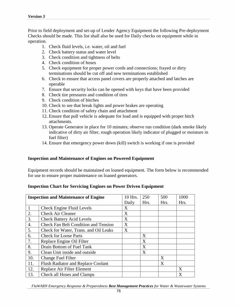
Version 3
FlaWARN Emergency Response & Preparedness Best Management Practices for Water & Wastewater Systems
76
Prior to field deployment and set-up of Lender Agency Equipment the following Pre-deployment
Checks should be made. This list shall also be used for Daily checks on equipment while in
operation.
1. Check fluid levels, i.e. water, oil and fuel
2. Check battery status and water level
3. Check condition and tightness of belts
4. Check condition of hoses
5. Check equipment for proper power cords and connections; frayed or dirty
terminations should be cut off and new terminations established
6. Check to ensure that access panel covers are properly attached and latches are
operable
7. Ensure that security locks can be opened with keys that have been provided
8. Check tire pressures and condition of tires
9. Check condition of hitches
10. Check to see that break lights and power brakes are operating
11. Check condition of safety chain and attachment
12. Ensure that pull vehicle is adequate for load and is equipped with proper hitch
attachments.
13. Operate Generator in place for 10 minutes; observe run condition (dark smoke likely
indicative of dirty air filter, rough operation likely indicator of plugged or moisture in
fuel filter)
14. Ensure that emergency power down (kill) switch is working if one is provided
Inspection and Maintenance of Engines on Powered Equipment
Equipment records should be maintained on loaned equipment. The form below is recommended
for use to ensure proper maintenance on loaned generators.
Inspection Chart for Servicing Engines on Power Driven Equipment
Inspection and Maintenance of Engine
10 Hrs.
Daily
250
Hrs.
500
Hrs.
1000
Hrs.
1 Check Engine Fluid Levels X
2. Check Air Cleaner X
3. Check Battery Acid Levels X
4. Check Fan Belt Condition and Tension X
5. Check for Water, Trans. and Oil Leaks X
6. Check for Loose Parts X
7. Replace Engine Oil Filter X
8. Drain Bottom of Fuel Tank X
9. Clean Unit inside and outside X
10. Change Fuel Filter X
11. Flush Radiator and Replace Coolant X
12. Replace Air Filter Element X
13. Check all Hoses and Clamps X
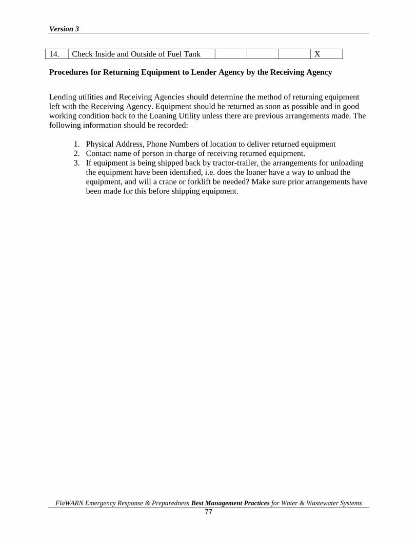
Version 3
FlaWARN Emergency Response & Preparedness Best Management Practices for Water & Wastewater Systems
77
14. Check Inside and Outside of Fuel Tank X
Procedures for Returning Equipment to Lender Agency by the Receiving Agency
Lending utilities and Receiving Agencies should determine the method of returning equipment
left with the Receiving Agency. Equipment should be returned as soon as possible and in good
working condition back to the Loaning Utility unless there are previous arrangements made. The
following information should be recorded:
1. Physical Address, Phone Numbers of location to deliver returned equipment
2. Contact name of person in charge of receiving returned equipment.
3. If equipment is being shipped back by tractor-trailer, the arrangements for unloading
the equipment have been identified, i.e. does the loaner have a way to unload the
equipment, and will a crane or forklift be needed? Make sure prior arrangements have
been made for this before shipping equipment.

Version 3
FlaWARN Emergency Response & Preparedness Best Management Practices for Water & Wastewater Systems
78
Chapter 11: Operating Agreement for Loaning and Receiving Equipment
Scope of Policy and Procedures
These Operating Policies and Procedures and the attached Forms have been found to be
extremely helpful to Agencies that Loan or Receive equipment used in post hurricane utility
restorations. These policies and procedures address the most common situations that develop and
provide effective methods for safeguarding loaned equipment.
Policy Statement
All equipment obtained by the Receiving Agency is subject to Receiving Agency control and
may be utilized only in accordance with established agreement between the Receiving and
Lending Agencies. Equipment obtained by the Receiving Agency includes that equipment
loaned or contracted by public or private Receiving Agencies, equipment received as a gift, or
obtained by other means.
Receiving Agencies that procure loaned equipment are responsible for its use, maintenance, and
safeguarding. Receiving Agencies are responsible for notifying the Loaning Agency of any
equipment status changes such as transfers, breakdowns, destruction, vandalism or theft of
loaned equipment.
Receipt and Protection of Equipment
The Receiving Agency shall designate a responsible party and receive equipment at a designated
Staging Area. The Designated Receiver Agent is established as the party responsible for securing
and safeguarding loaned equipment and is the official spokesperson for communications with the
Lending Agency about equipment matters. The Receiver Agent is responsible for tracking the
equipment that is deployed for use under this Agreement.
The Receiving Agent is responsible for obtaining relevant data for each piece of equipment,
assigning unique identification numbers, recording and maintaining the information on a tracking
form using a prescribed tracking system, and retaining equipment records for internal tracking
purposes.
The Receiving Agent is also responsible for coordinating the placement of equipment and for
maintaining equipment records that are precise and up-to-date.

Version 3
FlaWARN Emergency Response & Preparedness Best Management Practices for Water & Wastewater Systems
79
Receiving Agency Equipment Responsibilities
The Receiving Agency is responsible for ensuring that equipment is used for its designated
purpose and that it is properly secured, protected from accidental mishap, vandalism and
tampering. The Receiving Agency is responsible and accountable for all equipment provided
under the Agreement and agrees to hold harmless and protect the Loaner Agency from all
personal and private lawsuits, fines, and judgments imposed by any party, resulting from the
transport, placement, and operation of the Loaning Agency’s Equipment.
Lost, Damaged, Destroyed or Stolen Equipment
The Receiving Agent is required to have appropriate safeguards in place to prevent loss,
damage, destruction, vandalism, or theft of equipment.
If Loaned Agency equipment becomes damaged for any reason, it is the Receiving
Agency’s responsibility to notify the Loaning Agency as soon as the facts become
known. For the purpose of this Agreement damages consist of loss, damage, vandalism,
destruction or theft of equipment procured by the Receiving Agency.
Receiving Agency is responsible for any and all damages and shall repair or compensate
Loaner Agency as needed to return the equipment to the Loaner Agency in the condition
in which it was received by the Receiving Agency.
Equipment Information Requirements
The Parties shall maintain equipment and contact information for each piece of loaned
equipment. The following are minimum requirements for each Party to this Agreement.
Information to be Recorded and Maintained by Receiving Agency
1. Owner of Equipment
2. Manufacturer of Equipment
3. Type of Equipment
4. Identification # and Model # of Equipment
5. Authorized Party of Equipment
6. Physical and Mailing Address, Phone Numbers
7. Current Hours on Equipment
8. Physical Condition of Equipment
9. Who’s responsible for returning equipment
Version 3
FlaWARN Emergency Response & Preparedness Best Management Practices for Water & Wastewater Systems
80
Information to be Recorded and Maintained by Loaning Agency
1. Facility Name
2. Physical and Mailing Address, Phone Numbers
3. Location of Equipment, i.e. lift station #, water plant etc.
4. Location Physical Address, i.e. major intersection, street etc.
5. Authorized Party name, title and phone numbers
6. Who’s responsible for checking equipment, i.e. fueling, maintenance etc
7. Return / Delivery Method
Maintenance Checks to be Performed by Receiving Agency
The Receiving Agent shall be required to exercise prudent utility maintenance practices when
operating Loaning Agency equipment. Typical maintenance checks are described below:
Receiving Agency Maintenance and Daily Checks of Equipment
1. Equipment Start up and Shut down - periodic checks of equipment.
a. Perform minor maintenance checks, such as oil checks, battery, air filters, radiator
coolant levels, fan belt tension and fuel level checks on equipment.
b. Make sure the generator is level. With the dipstick inserted all the way, verify that
the oil level is maintained between the two notches on the dipstick. When
checking the engine oil, be sure to check if the oil is clean and viscous. If the oil is
not clean, drain the oil by removing the oil drain plug, and refill with the specified
amount of oil as outlined in the Engine Operator’s Manual.
c. Always maintain battery fluid level between the specified marks. Battery life will
be shortened, if the fluid level is not properly maintained. Add only distilled water
when replenishment is necessary. DO NOT over fill.
d. Periodic cleaning/replacement is necessary for the air filter.
e. Day-to-day addition of coolant is done from the reserve tank. When adding
coolant to the radiator, DO NOT remove the radiator cap until the unit has
completely cooled. Make sure the coolant level in the reserve tank is always
between the "H" and the "L" markings.
f. A loose fan belt may contribute to overheating, or to insufficient charging of the
battery. Inspect the fan belt for damage and wear and adjust or replace as needed.
g. Fill the fuel tank with clean and fresh diesel fuel. DO NOT fill the tank beyond
capacity. Pay attention to the fuel tank capacity when replenishing fuel.
Version 3
FlaWARN Emergency Response & Preparedness Best Management Practices for Water & Wastewater Systems
81
2. Perform routine preventative / corrective maintenance on equipment; for example:
a. Tires may need to be replaced or repaired if damaged.
b. Oil and filter may need to be changed and replaced after significant hours on
equipment.
c. Air filter and fuel filters may need to be replaced after significant hours on
equipment.
d. Cleaning and minor touch up painting may be needed on equipment.
Minimum Safety Requirements to be Employed by Receiving Agency
The Receiving agency agrees to conduct safety inspections, follow safety rules for equipment,
and also develop and conduct tailgate safety meetings to inform those responsible for the
transport, mobilization, set-up and operation of Loaning Agency equipment is conducted
according to prudent utility practices.
The Receiving agency agrees to refer to operating and maintenance manual for all equipment
safety procedures that are in question.

Version 3
FlaWARN Emergency Response & Preparedness Best Management Practices for Water & Wastewater Systems
82
Chapter 12: Transport of Equipment, Materials and Personnel to Staging Areas
Importance of Safety
Water and Wastewater utilities responding to calls for aid must do so in a safe and efficient
manner with sufficient equipment, materials, personnel, and supplies to be able to assist the
effected utility. They must also ensure that they are self-sufficient since equipment resources and
access may be severely stressed and/or unavailable. Listed are methods for the efficient and safe
movement of utility equipment over public roadways.
Pre-Vehicle Inspection
Prior to moving any equipment, basic pre-vehicle inspections should be made on each piece of
equipment that will be moved to the impacted site. These inspections guidelines are requirements
for CDL equipment and should be used for all equipment that travels on public roadways.
Pre-Trip Vehicle Inspection Checklist
Engine Compartment (Engine Off)
Leaks/Hoses
Look for puddles on the ground.
Look for dripping fluids on underside of engine and transmission.
Inspect hoses for condition and leaks.
Oil Level
Indicate where dipstick is located.
See that oil level is within safe operating range. Level must be above refill mark.
Coolant Level
Inspect reservoir sight glass, or (If engine is not hot), remove radiator cap and check for
visible coolant level.
Power Steering Fluid
Indicate where power steering fluid dipstick is located.
Check for adequate power steering fluid level. Level must be above refill mark.
Version 3
FlaWARN Emergency Response & Preparedness Best Management Practices for Water & Wastewater Systems
83
Engine Compartment Belts
Check the following belts for snugness (up to 3/4 inch play at center of belt), cracks, or
frays: power steering belt, water pump belt, alternator belt, air compressor belt. Note: If
any of the components listed above are not belt driven, you must make sure
component(s) are operating properly, are not damaged or leaking, and are mounted
securely.
Clutch/Gearshift
Depress clutch.
Place gearshift lever in neutral (or park, for automatic transmissions).
Start engine, then release clutch slowly.
Cab Check/Engine Start
Oil Pressure Gauge Make sure oil pressure gauge is working.
Check that pressure gauge shows increasing or normal oil pressure or that the warning
light goes off.
If equipped, oil temperature gauge should begin a gradual rise to the normal operating
range.
Temperature Gauge Make sure the temperature gauge is working.
Temperature should begin to climb to the normal operating range or temperature light
should be off.
Ammeter/Voltmeter Check that gauges show alternator and/or generator is charging or that warning light is
off.
Mirrors and Windshield
Mirrors should be clean and adjusted properly from the inside.
Windshield should be clean with no illegal stickers, no obstructions, or damage to the
glass.
Emergency Equipment Check for spare electrical fuses.
Check for three red reflective triangles.
Check for a properly charged and rated fire extinguisher.
Steering Play Non-power steering: Check for excessive play by turning steering wheel back and forth.
Play should not exceed 10 degrees (or about two inches on a 20-inch wheel).

Version 3
FlaWARN Emergency Response & Preparedness Best Management Practices for Water & Wastewater Systems
84
Power steering: With the engine running, check for excessive play by turning the steering
wheel back and forth. Play should not exceed 10 degrees (or about two inches on a 20-
inch wheel) before front left wheel barely moves.
Wipers/Washers Check that wiper arms and blades are secure, not damaged, and operate smoothly.
If equipped, windshield washers must operate correctly.
Lighting Indicators Test that dash indicators work when corresponding lights are turned on:
Left turn signal.
Right turn signal.
Four-way emergency flashers.
High beam headlight.
Horn Check that air horn and/or electric horn work.
Heater/Defroster/Air Conditioner Test that the heater, defroster and the air conditioner are working.
Parking Brake Check Apply parking brake only and make sure that it will hold the vehicle by shifting into a
lower gear and gently pulling against the brake.
Hydraulic Brake Check Pump the brake pedal three times, and then hold it down for five seconds. The brake
pedal should not move (depress) during the five seconds.
If equipped with a hydraulic brake reserve (back-up) system, with the key off, depress
the brake pedal and listen for the sound of the reserve system electric motor.
Check that the warning buzzer or light is off.
Air Brake Check (Air Brake Equipped Vehicles Only) Air brake safety devices vary. However, this procedure is designed to see that any safety
device operates correctly as air pressure drops from normal to a low air condition. For
safety purposes, in areas where an incline is present, you will use wheel chocks during
the air brake check. The proper procedures for inspecting the air brake system are as
follows:
– With the engine running, build the air pressure to govern cut-out (100-125 psi).
– Shut off the engine, chock your wheels, if necessary, release the tractor
protection valve and parking brake (push in), fully apply the foot brake and hold
it for one minute. Check the air gauge to see if the air pressure drops more than
three pounds in one minute (single vehicle) or four pounds in one minute
(combination vehicle).
– Begin fanning off the air pressure by rapidly applying and releasing the foot
brake. Low air warning devices (buzzer, light, flag) should activate before air
pressure drops below 60 psi.

Version 3
FlaWARN Emergency Response & Preparedness Best Management Practices for Water & Wastewater Systems
85
– Continue to fan off the air pressure. At approximately 40 psi on a tractor-trailer
combination vehicle, the tractor protection valve and parking brake valve should
close (pop out). On other combination vehicle types and single vehicle types, the
parking brake valve should close (pop out).
Safety Belt Check that the safety belt is securely mounted, adjusts, and latches properly.
Lights/Reflectors Check that all external lights and reflective equipment are clean and functional. Light and
reflector checks include:
– Clearance lights (red on rear, amber elsewhere).
– Headlights (high and low beams).
– Taillights.
– Turn signals.
– Four-way flashers.
– Brake lights.
– Red reflectors (on rear) and amber reflectors (elsewhere).
– Note: Checks of brake, turn signal and four-way flasher functions must be done
separately.
Steering
Steering Box/Hoses Check that the steering box is securely mounted and not leaking. Look for any missing
nuts, bolts, and cotter keys.
Check for power steering fluid leaks or damage to power steering hoses.
Steering Linkage See that connecting links, arms, and rods from the steering box to the wheel are not worn
or cracked.
Check that joints and sockets are not worn or loose and that there are no missing nuts,
bolts, or cotter keys.
Suspension
Springs/Air/Torque Look for missing, shifted, cracked, or broken leaf springs.
Look for broken or distorted coil springs.
If vehicle is equipped with torsion bars, torque arms, or other types of suspension
components, check that they are not damaged and are mounted securely.
Air ride suspension should be checked for damage and leaks.
Mounts Look for cracked or broken spring hangers, missing or damaged bushings, and broken,
loose, or missing bolts, u-bolts or other axle mounting parts. (The mounts should be
checked at each point where they are secured to the vehicle frame and axle[s]).
Shock Absorbers See that shock absorbers are secure and that there are no leaks.

Version 3
FlaWARN Emergency Response & Preparedness Best Management Practices for Water & Wastewater Systems
86
Note: Perform the same suspension components inspection on every axle (power unit and trailer,
if equipped).
Brakes
Slack Adjustors Look for broken, loose, or missing parts.
For manual slack adjustors, the brake rod should not move more than one inch (with the
brakes released) when pulled by hand.
Brake Chambers See that brake chambers are not leaking, cracked, or dented and are mounted securely.
Brake Hoses/Lines Look for cracked, worn, or leaking hoses, lines, and couplings.
Drum Brake Check for cracks, dents, or holes. Also check for loose or missing bolts.
Brake linings (where visible) should not be worn dangerously thin.
Brake Linings On some brake drums, there are openings where the brake linings can be seen from
outside the drum. For this type of drum, check that a visible amount of brake lining is
showing.
Note: Perform the same brake components inspection on every axle (power unit and trailer, if
equipped).
Wheels
Rims Check for damaged or bent rims. Rims cannot have welding repairs.
Tires The following items must be inspected on every tire:
Tread depth: Check for minimum tread depth (4/32 on steering axle tires, 2/32 on all
other tires).
Tire condition: Check that tread is evenly worn and look for cuts or other damage to
tread or sidewalls. Also, make sure that valve caps and stems are not missing, broken, or
damaged.
Tire inflation: Check for proper inflation by using a tire gauge, or inflation by striking
tires with a mallet or other similar device.
Hub Oil Seals/Axle Seals See that hub oil/grease seals and axle seals are not leaking and, if wheel has a sight glass,
oil level is adequate.
Lug Nuts
Check that all lug nuts are present, free of cracks and distortions, and show no signs of
looseness such as rust trails or shiny threads.

Version 3
FlaWARN Emergency Response & Preparedness Best Management Practices for Water & Wastewater Systems
87
Make sure all bolt-holes are not cracked or distorted.
Spacers If equipped, check that spacers are not bent, damaged, or rusted through.
Spacers should be evenly centered, with the dual wheels and tires evenly separated.
Note: Perform the same wheel inspection on every axle (power unit and trailer, if equipped).
Door(s)/Mirror(s) Check that door(s) are not damaged and that they open and close properly from the
outside.
Hinges should be secure with seals intact.
Check that mirror(s) and mirror brackets are not damaged and are mounted securely with
no loose fittings.
Fuel Tank Check that tank(s) are secure, cap(s) are tight, and that there are no leaks from tank(s) or
lines.
Battery/Box Wherever located, see that battery(s) are secure, connections are tight, and cell caps are
present.
Battery connections should not show signs of excessive corrosion.
Battery box and cover or door must be secure.
Drive Shaft Check that drive shaft is not bent or cracked.
Couplings should be secure and free of foreign objects.
Exhaust System Check system for damage and signs of leaks such as rust or carbon soot.
System should be connected tightly and mounted securely.
Frame Look for cracks, broken welds, holes or other damage to the longitudinal frame members,
cross members, box, and floor.
Rear of Vehicle
Splash Guards If equipped, check that splashguards or mud flaps are not damaged and are mounted
securely.
Doors/Ties/Lifts Check that doors and hinges are not damaged and that they open, close, and latch
properly from the outside, if equipped.
Ties, straps, chains, and binders must also be secure.
Version 3
FlaWARN Emergency Response & Preparedness Best Management Practices for Water & Wastewater Systems
88
If equipped with a cargo lift, look for leaking, damaged or missing parts and explain how
it should be checked for correct operation.
Lift must be fully retracted and latched securely.
Tractor/Coupling
Air/Electric Lines
Listen for air leaks. Check that air hoses and electrical lines are not cut, chafed, spliced,
or worn (steel braid should not show through).
Make sure air and electrical lines are not tangled, pinched, or dragging against tractor
parts.
Catwalk Check that the catwalk is solid, clear of objects, and securely bolted to tractor frame.
Mounting Bolts Look for loose or missing mounting brackets, clamps, bolts, or nuts. Both the fifth wheel
and the slide mounting must be solidly attached.
On other types of coupling systems (i.e., ball hitch, pintle hook, etc.), inspect all coupling
components and mounting brackets for missing or broken parts.
Locking Jaws Look into fifth wheel gap and check that locking jaws are fully closed around the
kingpin.
On other types of coupling systems (i.e., ball hitch, pintle hook, etc.), inspect the locking
mechanism for missing or broken parts and make sure it is locked securely. If present,
safety cables or chains must be secure and free of kinks and excessive slack.
Platform (Fifth Wheel) Check for cracks or breaks in the platform structure, which supports the fifth wheel skid
plate.
Release Arm (Fifth Wheel) If equipped, make sure the release arm is in the engaged position and the safety latch is in
place.
Kingpin/Apron/Gap Check that the kingpin is not bent.
Make sure the visible part of the apron is not bent, cracked, or broken.
Check that the trailer is laying flat on the fifth wheel skid plate (no gap).
Locking Pins (Fifth Wheel) If equipped, look for loose or missing pins in the slide mechanism of the sliding fifth
wheel. If air powered, check for leaks.
Make sure locking pins are fully engaged.
Check that the fifth wheel is positioned properly so that the tractor frame will clear the
landing gear during turns.
Emergency Equipment

Version 3
FlaWARN Emergency Response & Preparedness Best Management Practices for Water & Wastewater Systems
89
In addition to checking for spare electrical fuses (if equipped), three red reflective
triangles, and a properly charged and rated fire extinguisher.
Lighting Indicators In addition to checking the lighting also check the following lighting indicators (internal
panel lights):
– Alternately flashing amber lights indicator, if equipped.
– Alternately flashing red lights indicator.
– Strobe light indicator, if equipped.
Lights/Reflectors In addition to checking the lights and reflective check the following (external) lights and
reflectors:
– Strobe light, if equipped.
– Stop arm light, if equipped.
– Alternately flashing amber lights, if equipped.
– Alternately flashing red lights.
Seating Look for broken seat frames and check that seat frames are firmly attached to the floor.
Check that seat cushions are attached securely to the seat frames.
Securing Cargo
Cargo that is not secure or loaded incorrectly can be a danger. Loose cargo that falls off a vehicle
can cause traffic problems and others could be hurt or killed and loose cargo could hurt or kill
during a quick stop or crash. The vehicle could be damaged by an overload. Steering could be
affected by how a vehicle is loaded, making it more difficult to control the vehicle.
The driver is responsible for the following elements relating to properly loading and securing
the cargo:
Inspecting the cargo
Recognizing overloads and poorly balanced weight
Knowing the cargo is properly secured and does not obscure the view ahead or to the
sides
Knowing the cargo does not restrict access to emergency equipment

Version 3
FlaWARN Emergency Response & Preparedness Best Management Practices for Water & Wastewater Systems
90
Pulling Trailers or other Combination Vehicles
Combination vehicles (those pulling trailers, generators, lowboys) are usually heavier, longer,
and require more driving skill than single commercial vehicles. This means that drivers of
combination vehicles need more knowledge and skill than drivers of single vehicles
Rollover Risks
More than half of truck driver deaths in crashes are the result of truck rollovers. When more
cargo is piled up in a truck, the "center of gravity" moves higher up from the road. The truck
becomes easier to turn over. Fully loaded rigs are ten times more likely to roll over in a crash
than empty rigs.
The following two things will help prevent rollover--keep the cargo as close to the ground as
possible, and driving slow around turns. Keeping cargo low is even more important in
combination vehicles than in straight trucks. Also, keep the load centered on the rig. If the load is
to one side it makes a trailer lean, and rollover is more likely. Make sure the cargo is centered
and spread out as much as possible.
Rollovers happen when you turn too fast. Drive slowly around corners, on ramps, and off ramps.
Avoid quick lane changes, especially when fully loaded.
Towing Safety Precautions
The following guidelines are to be used when towing loads.
Make sure the hitch and coupling of the towing vehicle are rated equal to, or greater than
the trailer "gross vehicle weight rating" (GVWR).
ALWAYS inspect the hitch and coupling for wear. NEVER tow a trailer with defective
hitches, couplings, chains etc.
Check the tire air pressure on both towing vehicle and trailer. Also check the tire treads
wear on both vehicles.
ALWAYS make sure the trailer is equipped with a "Safety Chain".
Towing Precautions for Transporting Portable Generators and Pumps
ALWAYS attach trailer's safety chain to bumper of towing vehicle.
ALWAYS make sure the vehicle and trailer directional, backup, brake, and trailer lights
are connected and working properly.
The maximum speed unless otherwise posted for highway towing is 55 MPH. It is not
recommended for off-road towing. However, if necessary, do not exceed 15 MPH or less
depending on type of terrain to prevent damage to the axles.
Version 3
FlaWARN Emergency Response & Preparedness Best Management Practices for Water & Wastewater Systems
91
Place chocked blocks underneath wheel to prevent rolling, when parked.
Place support blocks underneath the trailer's bumper to prevent tipping, when parked.
Use the trailer's hand winch to adjust the height of the trailer, then insert locking pin to
lock wheel stand in place, when parked.
Avoid sudden stops and starts. This can cause skidding, or jackknifing. Smooth, gradual
starts and stops will improve gas mileage.
Avoid sharp turns to prevent rolling.
Remove wheel stand when transporting.
DO NOT transport generator with fuel vent in place. Always install plug.
Steering Precautions with Combination Vehicles
Trucks with trailers have a dangerous "crack-the-whip" effect. When you make a quick lane
change, the crack-the-whip effect can turn the trailer over. There are many accidents where only
the trailer has overturned.
"Rearward amplification" causes the crack-the-whip effect and is most pronounced in quick lane
changes. Steer gently and smoothly when you are pulling trailers. If you make a sudden
movement with your steering wheel, your trailer could tip over.
Follow far enough behind other vehicles (at least 1 second for each 10 feet of your vehicle
length, plus another second if going over 40 mph). Look far enough down the road to avoid
being surprised and having to make a sudden lane change. At night, drive slow enough to see
obstacles with your headlights before it is too late to change lanes or stop gently. Slow down to a
safe speed before going into a turn.
Braking Precautions when Hauling Cargo or Operating Combination Vehicles
Control your speed whether fully loaded or empty. Large combination vehicles take longer to
stop when they are empty than when they are fully loaded. When lightly loaded, the very stiff
suspension springs and strong brakes give poor traction and make it very easy to lock up the
wheels. The trailer can swing out and strike other vehicles and can jackknife very quickly. Also
must be very careful about driving "bobtail" tractors (tractors without semi trailers). Tests have
shown that bobtails can be very hard to stop smoothly. It takes them longer to stop than a tractor-
semi trailer loaded to maximum gross weight.
In any combination rig, allow lots of following distance and look far ahead, so you can brake
early. Don't be caught by surprise and have to make a "panic" stop.

Version 3
FlaWARN Emergency Response & Preparedness Best Management Practices for Water & Wastewater Systems
92
Considerations for Railroad-Highway Crossings
Railroad-highway crossings can also cause problems, particularly when pulling trailers with low
underneath clearance.
These trailers can get stuck on raised crossings:
Low slung units (lowboy, car carrier, moving van, possum-belly livestock trailer).
Single-axle tractor pulling a long trailer with its landing gear set to accommodate a
tandem-axle tractor.
If for any reason you get stuck on the tracks, get out of the vehicle and away from the tracks.
Check signposts or signal housing at the crossing for emergency notification information. Call
911 or other emergency number. Give the location of the crossing using all identifiable
landmarks, especially the DOT number, if posted.
Preventing Trailer Skids
When the wheels of a trailer lock up, the trailer will tend to swing around. This is more likely to
happen when the trailer is empty or lightly loaded. This type of jackknife is often called a "trailer
jackknife:
The procedure for stopping a trailer skid is:
Recognize the Skid. The earliest and best way to recognize that the trailer has started to
skid is by seeing it in your mirrors. Any time you apply the brakes hard, check the
mirrors to make sure the trailer is staying where it should be. Once the trailer swings out
of your lane, it's very difficult to prevent a jackknife.
Stop Using the Brake. Release the brakes to get traction back. Do not use the trailer
hand brake (if you have one) to "straighten out the rig." This is the wrong thing to do
since the brakes on the trailer wheels caused the skid in the first place. Once the trailer
wheels grip the road again, the trailer will start to follow the tractor and straighten out.
Turning and Backing Combination Vehicles
When a vehicle goes around a corner, the rear wheels follow a different path than the front
wheels. This is called off-tracking or "cheating." The Figures on the following page show how
off-tracking causes the path followed by a tractor to be wider than the rig itself. Longer vehicles
will off-track more. The rear wheels of the powered unit (truck or tractor) will off-track some,
and the rear wheels of the trailer will off-track even more. If there is more than one trailer, the
rear wheels of the last trailer will off-track the most. Steer the front end wide enough around a
corner so the rear end does not run over the curb, pedestrians, etc. However, keep the rear of

Version 3
FlaWARN Emergency Response & Preparedness Best Management Practices for Water & Wastewater Systems
93
your vehicle close to the curb. This will stop other drivers from passing you on the right. If you
cannot complete your turn without entering another traffic lane, turn wide as you complete the
turn. This is better than swinging wide to the left before starting the turn because it will keep
other drivers from passing you on the right.

Version 3
FlaWARN Emergency Response & Preparedness Best Management Practices for Water & Wastewater Systems
94
Backing with a Trailer.
When backing a car, straight truck, or bus, you turn the top of the steering wheel in the direction
you want to go. When backing a trailer, turn the steering wheel in the opposite direction. Once
the trailer starts to turn, turn the wheel the other way to follow the trailer.
Whenever backing up with a trailer, try to position the vehicle so it will back in a straight line. If
backing on a curved path, back to the driver's side for better visibility.
Look at the line of travel before beginning. Get out and walk around the vehicle. Check the
clearance to the sides and overhead, in and near the path of the vehicle.

Version 3
FlaWARN Emergency Response & Preparedness Best Management Practices for Water & Wastewater Systems
95
Check the outside mirrors on both sides frequently. Get out of the vehicle and re-inspect the path
if unsure.
Back Slowly. This allows for corrections before getting too far off course.
Correct Drift Immediately. As soon as you see the trailer getting off the proper path, correct it by
turning the top of the steering wheel in the direction of the drift.
Pull Forward. When backing a trailer, make pull-ups to re-position the vehicle as needed.
Driver’s License Requirements
It is important that drivers only operate equipment that they are legally licensed to drive. Failure
to adhere to these requirements can lead to a serious accidents and result in both significant
personal liability to the unlicensed driver as well as liability to the agency.
Commercial Driver Licenses (CDL)
Class A: Commercial motor vehicles - trucks or truck combinations weighing with a
Gross Vehicle Weight Rating of 26,001 lbs. or more, provided towed vehicle is more
than 10,000 lbs.
Class A exam requirements - Minimum age 18
General Knowledge test
Combinations vehicle test
Air Brakes
Applicable endorsement exams
Vision - 20/40 in each eye
Hearing - must hear a whisper
Pre-trip
Basic skills
Driving
Note: Drivers under 21 years of age will be restricted to intrastate operation only.
Class B: Commercial motor vehicles - straight trucks weighing 26,001 lbs. Gross Vehicle
Weight Rating or more.
Class B exam requirements
General Knowledge test
Air brakes if applicable
Vision - 20/40 in each eye
Hearing - must hear a whisper

Version 3
FlaWARN Emergency Response & Preparedness Best Management Practices for Water & Wastewater Systems
96
Pre-trip (not required for Class C)
Basic skills (not required for Class C)
Driving
Note: Drivers under 21 years of age will be restricted to intrastate operation only.
Class C: Vehicles transporting placard able amounts of hazardous materials, or vehicles
designed to transport more than 15 persons including the driver with a Gross Vehicle
Weight Rating of less than 26,001 lbs.
Class C exam requirements
General Knowledge test
Air brakes if applicable
Vision - 20/40 in each eye
Hearing - must hear a whisper
Pre-trip (not required for Class C)
Basic skills (not required for Class C)
Driving
Note: Drivers under 21 years of age will be restricted to intrastate operation only.
Non-Commercial Driver Licenses
Class E: Any non-commercial motor vehicles with Gross Vehicle Weight Rating
(GVWR) less than 26,001 pounds, including passenger cars, 15 passenger vans including
the driver, trucks or recreational vehicles and two or three wheel motor vehicles 50 cc or
less, such as mopeds or small scooters (see below). Farmers and drivers of authorized
emergency vehicles who are exempt from obtaining a commercial driver license must
obtain a Class E license.
Emergency Food Considerations
After determining the number of personnel to be sent, make sure there are enough supplies (food,
water, fuel) to keep the group self-sufficient for at least five days. There is a possibility that
personnel may arrive before other emergency supplies so take into account all basic needs before
departing to a stricken area.
Transportation and Other Equipment Fuel Considerations
All vehicles, as well as equipment, should use the same fuel type. Past disaster response
activities have shown fuel to be in short supply, especially gasoline. Diesel seemed to be easier
to come by but don’t count on any fuel being available. If all equipment uses the same fuel, then
only one type of fuel needs to be hauled while on the road. Coordination with other local and
responder utilities is essential.

Version 3
FlaWARN Emergency Response & Preparedness Best Management Practices for Water & Wastewater Systems
97
Suggestions for Providing and Equipping a Service Truck
A service truck with spare tires, a compressor, spare parts, and a trained mechanic for vehicles
and equipment is a must. You will be driving into an area where debris will be prevalent and
tires will be damaged. Service station and or tire shops may not be available in the effected areas
and the damaged utility may not be able to provide any help. There is also the possibility of
breakdowns along the way to or from the effected area.
Equipment Security Provisions
Make sure all equipment is secured and locked. Unfortunately, experience has shown that,
supplies have been taken from vehicles at staging areas and other places. Backhoes, tractors and
other heavy equipment need to be secured for a long haul over interstate highways as well as
back roads.
Mapping and Locating Unfamiliar Facilities
A Global Positioning System (GPS) with back-up hand maps are very helpful in locating both
equipment that is deployed in unfamiliar areas and for locating landmarks. These are
recommended for inclusion with each vehicle. Maps of the area can be obtained from
convenience stores. This allows the convoy to keep moving even if a few get separated or have
to stop for repairs. Also, street signs and utility markers (as well as buildings!) may not be
available for locating sites in the affected area. A plan defining checkpoints along the way needs
to be clearly communicated to every driver before deploying. In the even of separation, each
driver should know where the next stop is and can wait for others to catch up.
Vehicle to vehicle radios for communication during travel and upon arrival should be in every
vehicle. With these the convoy can stay notified if changes are to be made while traveling with
out stopping. Spare radios, batteries and charging/power units should be taken as well.
Movement of Equipment and Personnel on Public Roadways
Traveling in convoys can be very dangerous since other drivers will attempt to go around and cut
in creating potentials for accidents. It is very important to observe proper driving rules and to
travel at or below posted speeds. Safe breaking distances should always be maintained. The
primary objective of travel is to arrive safely with no accidents.
Considerations for Driver Fatigue
Employees may be in for a long drive. Make sure that there are relief drivers in every vehicle, so
drivers may rotate every few hours. Under no conditions should a driver be allowed to drive for

Version 3
FlaWARN Emergency Response & Preparedness Best Management Practices for Water & Wastewater Systems
98
more than 8 consecutive hours. Fatigue will cause accidents. Each driver should be familiar with
the preplanned route.
A lead and rear truck should be established so everyone has a vehicle to follow and one
responsible for brining up the rear so no one gets left behind. Communication between these
trucks is essential.
Reporting to a Staging Area
Your first destination may be a staging area. Upon arrival, report in to the staging area
coordinator. They may be able to assist with disaster placards for your vehicles, food, fuel, and
personnel identification. This will also let others know you are working in the area so they can be
on the lookout for you.
Expected Disaster Area Conditions
To safely and rapidly convoy to a disaster area requires planning. Without a plan, you run the
risk of adding to an already bad situation. Self-sufficiency cannot be understated. When you
arrive, more than likely there will be no water, no food, and no fuel. You may encounter
exhausted and stressed out responders and survivors. Roll in ready to relieve these workers as
they may need to deal with family and other issues or may not be available at all.
If you are equipped, supplied and ready to work, your restoration efforts will be much more
effective.

Version 3
FlaWARN Emergency Response & Preparedness Best Management Practices for Water & Wastewater Systems
99
Chapter 13: Effective Staging Area Set Up
Figure 1
Example of a Staging Area Near Work Location
School or
Utility
Compound
Useful for
Showers and
Sleeping Areas
Parking Area
Useful for
Pickup and
Transport
Vehicles
Recreation or Storage Yard
Very Large Areas Suitable For Large
Equipment, including Campers, Semi’s, Utility
Trucks and Materials Storage
This depiction is not typical, however does show some points that are key, such as sleeping and
bath areas in an air conditioned building and expanded unpaved parking area for large vehicles.
(Note limited access to site and location of large major highway nearby.)
Security Fencing
Main
Entrance
Rear Entrance

Version 3
FlaWARN Emergency Response & Preparedness Best Management Practices for Water & Wastewater Systems
100
Staging Area Planning
Staging areas should be located as close as possible to work locations or travel time will
greatly decrease productive work time. They should not be located farther than 45
minutes from any work site.
Staging area should be located and secured by Requesting Utility or Agency.
If at all possible, provide responders with maps to assist in locating the staging area after
nightfall. Many lights may be out further complicating landmark visibility.
Please refer to the attached layout. This may or may not resemble an actual site, however
some key points are shown: highway location, security, sleeping and shower
arrangements, and parking area suitable for heavy equipment and large trucks.
Some locations may not have all these elements and you may be forced to settle for less
than these. However, some meager (at best) responder comforts will go a long way to
speeding up the water and wastewater recovery.
Succession planning is important to note here. A seamless response effort is successful if
planned ahead. As quickly as possible after initial staging area set-up, communicate
staging area conditions including location, food and fuel provisions, to the next response
team. This progress report will be vital in replacement response crew effectiveness.
Staging Area Housekeeping, Organization and Cleanliness
It may be useful to note that some planning will be necessary to maintain your site in as
clean a manner as possible. Housekeeping, organization and cleanliness is important
since animals, rodents and insects will be attracted to unsanitary conditions.
You may need to have some members of your staff locate and place trash containers at
several locations in the staging area.
Each day the trash will need to be cleaned up, and moved to a large dumpster.
It may be possible to locate a waste management facility near the staging area and task
them with the job of removing trash dumpsters.
Housekeeping will include maintaining showers and bath facilities. Probably the best
time to meet this challenge is at the coordination meetings. It may be necessary to rotate
this duty around to several of the team members.
Normally, during the course of responses, some of the responders may report in to the
staging area during the day to refuel or pick up parts or materials, you may need to enlist
help from these crews in this effort.
Version 3
FlaWARN Emergency Response & Preparedness Best Management Practices for Water & Wastewater Systems
101
Chapter 14: Dealing with Post-Hurricane Shock, Stress and Trauma
Recognizing Post Traumatic Stress
When entering storm-ravaged areas, it can be hard to comprehend the misery and the utter and
total destruction of the area. Being prepared to simply get down to work is the best thing
responding utilities can do. Knowing that nothing will come easy will be obvious and must not
act as a deterrent. It is important to render assistance and get water flowing and sewage flows
contained. Be prepared for situations where people are not ready to think and act rationally and
may be more worried about their family and their community than providing assistance. Good
judgment in these situations is critical so appropriate action can be taken and no one becomes a
hindrance. Through the responders’ hard work, hope will replace despair and that’s an important
step in the recovery of a community.
Sometimes people face situations that are so traumatic that they may become unable or impaired
in coping and functioning effectively following the devastation resulting from a severe hurricane.
For these people, getting beyond the trauma and overcoming the post traumatic stress requires
consideration on the part of the responder. The symptoms experienced are much like those of a
Post Traumatic Stress Syndrome disorder. Specifically:
Confusion and distraction may develop following exposure to extreme trauma.
Extreme trauma is a terrifying event or ordeal that a person has experienced, witnessed or
learned about, especially one that is life threatening or causes physical harm. It can be a
single event such as a hurricane that has overwhelmed them with the degree of
destruction and the current facility conditions
The experience causes that person to feel an intense sense of helplessness.
The stress caused by trauma can affect all aspects of a person’s life, including mental,
emotional and physical well-being.
Research suggests that prolonged trauma may disrupt and alter brain chemistry.
Additionally operating managers may be taxing their mental and physical ability to function
because of fatigue. In many cases 16-hour days for weeks at a time may be the norm. Managers
under these conditions may exhibit signs of:
Loss of Concentration and Focus
Loss of Appetite
Memory Loss
Irritability
Becoming Overly Opinionated
Confusion, Numbness, and Flashbacks
Inability to interpret incomplete and ever-changing field Information

Version 3
FlaWARN Emergency Response & Preparedness Best Management Practices for Water & Wastewater Systems
102
Anger and Frustration caused by, upper management demands or the slow
pace of restoration
Responders should also expect to encounter management frustration resulting from the inability
to respond to personal issues related to their family or to the status of personal property that has
been damaged. Managers will also be faced by large-scale job abandonment that may approach
as much as 80percent.
Recognizing Effects of Post Traumatic Stress in the Work Place
Empathy and recognition of stressful conditions is most helpful in dealing with effected
managers in when post stress conditions have been identified. Effective integration of the
response team is usually optimized when the responder helps the receiving manager to recognize
his/her fatigue and helps him/her to refocus on differentiating between high and low priorities.
Once the capability of the responder is recognized, the receiving manager can be encouraged to
get proper rest and shore up personal problems.
Emotional preparation for responders is also important. Personnel should be instructed as to what
to expect in damaged areas, made aware of the working conditions, lack of prepared food and
other commonly available essentials and advised against sightseeing, scavenging and picture
taking unless they are pertinent for documenting damages.
Preparation should also include instructions on being patient and understanding that there will be
some confusion and inefficiencies in work assignments and these should be expected and will
improve as information and conditions improve. Responder personnel should be reminded that
assistance is always to be evaluated by the receiver not the responder.
Recognizing the symptoms of stress in receiving agency managers can be helpful in opening
dialog that can facilitate improved restoration prioritization. The following responses should be
expected in stressed and fatigued managers:
Characteristics of Stressed and Fatigued Managers
Expect a holding pattern and transition as responders build credibility
Expect focus on non-optimal priorities and “tunnel vision” caused by sensory
overload and shutdown by the receiving manager
Expect unnecessary bureaucracy and inefficient SOPs and work procedures that are
time consuming, inefficient and inappropriate for the emergencies
Expect rejection of outside help or feeling disappointed with the level of outside help

Version 3
FlaWARN Emergency Response & Preparedness Best Management Practices for Water & Wastewater Systems
103
Minimizing Post-Hurricane Stress for Operating Managers
The most effective method of relieving stress is quick integration of the Responder’s work force
into the restoration environment. Thus, those systems that have high levels of pre-storm planning
and preparations will be easier to transition than those systems that do not.
Effective Measures for Dealing with Stressed Utility Managers and Staff
Effectively working with stressed utility staff can be improved by using the following
techniques:
Effective Measures for Dealing with Stressed Utility Managers and Staff
Demonstrate empathy for the facility condition and responsibility of the utility
operating manager
Assure the manager that your purpose is to provide assistance
Listen to the problems without suggesting alternate solutions
Attempt to understand the predicament from the manager’s viewpoint and from the
demands placed on him/her by the supervisor, system failure or health hazard
Explain what resources are available and how they might be immediately deployed to
assist
Establish credibility by performing assisting actions and maintaining a commitment
to assist; never show frustration or apathy over restoration or restoration assignments
Keep communication with the manager timely and relevant

Version 3
FlaWARN Emergency Response & Preparedness Best Management Practices for Water & Wastewater Systems
104
Chapter 15: Power Outages and Procedures for Emergency Generator Installations
Introduction
Hurricanes are notorious for destroying overhead electric infrastructure and in many situations
the devastation is considerable. Power restoration can take several weeks or even months and
during this time period small water and wastewater systems will be without power making
normal life activities and access to basic necessities such as food, water, and sanitation extremely
difficult and stressful to those effected.
The lack of power, coupled with flooding and loss of sanitation, results in acute health concerns.
Wells, normally dry and protected become either inundated or impacted by groundwater that is
now under the influence of contaminated surface water caused by inoperative wastewater
treatment facilities and resultant sewage discharge. Pathogens such as Giardia, Cryptosporidium,
Salmonella, Shigella and viruses such as Hepatitis E and Rotavirus can be present in raw sewage
and as long as power is out, direct pathways to drinking water can be present. Lack of power,
access to and knowledge of the proper application of disinfectants to sterilize water renders all
forms of water excluding bottled water from secure sources, as potentially harmful to the public.
Given this scenario, the reestablishment of power to waster and to wastewater treatment facilities
is paramount in restoring normal conditions and protecting public health. Because the time
needed to restore electric power can be long and uncertain, small emergency power generators
must be employed to power both public and private water and wastewater treatment facilities.
These guidelines examine the proper procedures for selection, installation, and maintenance
procedures to ensure safe and reliable application of this type of generating equipment. They are
not intended to supersede the guidance or the experience of a certified electrician.
Identifying Power Requirements
In making emergency power generation selection, it is first necessary to determine the voltage
and amperage requirements of the facility to be powered by the generator.
Electrical connections to public and private water and wastewater treatment facilities generally
require three phase power. The power company via transformers that reduce overhead line
voltage into a voltage that can power electrical motors supplies three-phase power and other
devices used in the treatment facilities. There are a wide variety of voltages that are supplied for
these types of equipment applications by the power company. The table below illustrates the
possible voltages and configurations for electrical supply from the power company to service
plant equipment.

Version 3
FlaWARN Emergency Response & Preparedness Best Management Practices for Water & Wastewater Systems
105
Typical Transformer Load Configurations from Power Company to Plant Equipment
Power Transformer
Load Configuration
Single
Phase
Three
Phase
Single Phase, 3-Wire 120 V
240 V
Not
Available
Wye, Three Phase, 4-Wire
(208/120 V)
120 V
208 V
208 V
Wye, Three Phase, 4-Wire
(480/277 V)
277 V
480 V
480 V
Delta, Three Phase, 3 Wire
(240 V)
240 V 240 V
Delta, Three Phase, 3 Wire
(480 V)
480 V 480 V
Open Delta, 3 Phase, 3 Wire
(240 V)
240 V 240 V
As can be observed from the table, the power company supplies voltage in two different
configurations Wye or Delta. The difference between them is that in the 120/208Y configuration,
the phase to neutral voltage is the same 120V between all three legs.
Identification of Three Phase Wye Power Feed
As shown below in this configuration 120 volts can be derived from any phase to neutral
connection.
Identification of a Delta Power Connection
In a Delta connection, the 120V can be derived from only two of the three phases to neutral
connections. This is shown below:

Version 3
FlaWARN Emergency Response & Preparedness Best Management Practices for Water & Wastewater Systems
106
In this case, the 120V connection must be derived from connections one or two. Connection
three is called a “high leg” and must be identified by the power company. If this leg is
improperly connected, 208 volts will be supplied to120 volt equipment which will lead to
equipment damage and/or a possible heating of circuits that could lead to combustion.
It is important to note that three phase equipment does not operate on neutral to ground and it
does not matter which how the phases are connected. It only becomes important if the voltage is
used to supply auxiliary 120V to other equipment.
Typically, the high leg will be identified by the power company by a marking or tape on the
incoming wire at the top of the breakers or at the electric meter, or it can be determined using a
volt meter by measuring phase to ground. Unfortunately, there are not electric utility standards
for the high leg configuration and it must be identified in the field.
Voltage Supply Availability from Three Phase Generators
Table 2 illustrates the commercially available generators in ranges from 20 KW to 200 KW for
the various configurations for three-phase standby power. Standby power application is provided
for supplying emergency power for normal power interruptions. These types of units do not
provide sustained overload capacity. Generators are available for applications up to 2700 KW for
larger treatment facilities.
Prior to making a generator connection, it will be necessary to determine the voltage
requirements of the facility where power is to be supplied. The voltage needs can be identified
from the equipment inside the motor control panel, from electrical drawings when available or
from ratings found on the nameplates fixed to plant equipment.
Some generators will have switches that allow the generator to supply different voltages.

Version 3
FlaWARN Emergency Response & Preparedness Best Management Practices for Water & Wastewater Systems
107
Table 2
Available Three Phase Voltage Options for Commercially Available Generators
Ranges from 20 to 150 KW Sizes
Three Phase
Generator Options
120/208 V
127/220 V
139/240 V
120/240 V
240/416 V
254/440 V
277/480 V
To avoid damage to plant equipment, it is essential in making an electrical connection that the
voltage requirements of the plant equipment be identified. Voltage requirements will be found on
the motor nameplate.
Sizing of Generators for Powering Facility Equipment
Sizing the generator for power needs requires knowledge of the equipment to be operated at the
treatment plant. This requires that the amperage draw of each piece of equipment be known. This
analysis is important because generators continuously operating generators at 30 percent less
than the rated load can lead to engine damage.
A generator can be best sized if it can be determined from a direct match with the transformer
provided by the power company. In this instance one must determine the wye or delta
arrangement and ensure that the load is supplied by either one line transformer providing three
phase power or three line transformers providing step down power to each phase.
If two transformers are used to provide three phase power the available power or KW is only 87
percent of the summation of the KW rating of the two transformers. For example if two 25 KW
transformers are provided the available KW is (2 x 25 x .87percent =) 43.5 KW.
Lacking power company transformer service information, it would be necessary to determine the
KW generator needs by summing the horsepower requirements of all plant equipment that is to
be operated. Because the equipment used may not be efficiently designed, it is common to add a
20percent additional power requirement to account for power factor adjustment. In general, for a
temporary installation, a good rule of thumb is to size a generator from 1.5 to 2.0 times the
total horsepower requirements.

Version 3
FlaWARN Emergency Response & Preparedness Best Management Practices for Water & Wastewater Systems
108
Transport and Set Up of Generators
Generators may be supplied as either skid mounted or trailer mounted units. With the larger skid
mounted units, lifting, transport and set up at the emergency site will require specialized
equipment.
Various trailer connections may be supplied for portable generators. The receiver hitch is the
primary device that is attached to the rear of the vehicle that allows towing. There are six classes
of hitches. It is very important to choose the correct class of receiver hitch. Gross trailer weight
and tongue weight will determine the hitch that is needed. The two most common are ball and
military hitch type connections. Ball type connections may be in 1 7/8”, 2” or 2 5/16” diameters.
Unfortunately these sizes are not interchangeable and using a smaller diameter ball with a larger
diameter trailer mount is extremely dangerous since the trailer can come loose during transport to
the emergency site. Never exceed the lowest rating of any component of a towing system. Safety
chains are a requirement and should be crossed under the tongue of the trailer so that the tongue
will not drop to the road if it becomes separated from the hitch. Always leave enough slack so
you can turn. Never allow the safety chains to drag on the ground and never attach the safety
chains to the bumper because the weight of the generator can pull the bumper loose from a
vehicle.
Allowable Pull Vehicle and Towing Weights for Generators
It is recommended that at a minimum a ¾ ton pickup or larger be used to pull trailer-mounted
generators to ensure safe travel control and site maneuverability. The vehicle should always be
equipped with the proper hitch and the trailer and tongue weights should not exceed the pull
vehicle’s specifications. Many times generator units must be pulled in sloped or wet areas and
four-wheel drive vehicles are preferable.
Table 3
Gross Trailer Weight Allowances for Ball Type Hitches
Class Gross Trailer Weight (lbs) Nominal Size Receiver Ball (inches)
Class 1 1000 to 2500 1 7/8
Class 2 3500 2
Class 2.5 4,000 2 and above
Class 3 6,000 2 and above
Class 4 8,000 2 and above
Class 5 10,000 2 and above

Version 3
FlaWARN Emergency Response & Preparedness Best Management Practices for Water & Wastewater Systems
109
Lifting of skid mounted generator units also requires pre-planning. Smaller units may be lifted
with a front-end loader and transported to the site via trailer where it will again have to be lifted
and set. Larger units will require the use of a boom truck since placing the unit on the trailer and
lifting it in place at the site will require specialized equipment.
Weights and Lifting Considerations for Three Phase Generators
The weight of skid-mounted units is shown below. Moving of these units will require equipment
rated for these lifting capacities and proper rigging and use of slings and cables to prevent injury
to workers and damage to equipment.
Table 4
Available KW Sizes and Weight for Commercially Available Generators
Size in KW for
Standby Power
Wet
Weight (lbs)
20 950
25 1371
35 1668
40 1668
50 1720
60 1720
80 2000
100 2600
125 2600
150 3340
175 3350
200 6090
Connecting a Three Phase Generator to Water and Wastewater Facilities
Generators are typically provided with four wire (three wires plus ground) connectors called “pig
tails” that can be directly plugged into electrical control cabinets fitted with a disconnect switch.
In the “On” position, the disconnect switch isolates the generator connection from the main
power supply. In most cases these types of disconnect switches are not installed and even when
they are installed, the type of connector provided with generator widely varies, making a direct
match highly unlikely. For this reason generator connections must be direct wired to the
incoming breaker inside the power control cabinet. It will be necessary to cut the manufacture’s
supplied pigtail connection and direct wire the conductor to the top of the breaker.
If generator connections have been made in the past, the ends of the wires become frayed and
should not be used in this condition. The installer should cut the ends with a hacksaw and strip

Version 3
FlaWARN Emergency Response & Preparedness Best Management Practices for Water & Wastewater Systems
110
the wires back to a proper seat length to ensure a tight connection and to prevent an arcing
condition that can lead to equipment damage.
Figure 2
Connecting a 3 Phase Power Generator to Customer Power Control Center or to Transfer
Switch
Considerations for Sizing Generator Conductors
Some generators may be supplied without conductor. In these cases the generator conductor must
be sized to carry the current required by the installation. Additionally, it must be capable of
operating in a wet condition. Because each installation will vary, it is wise to standardize on a
conductor type and size that can be used successfully at each installation. Because emergency
generation installation will typically be performed for a wide variety of installations with limited
up-front information it is wise to carry standard conductor of a size and type that can be used for
Feed
From
Power
Company
To
Ground
Directions for “No Transfer
Switch” Condition:
1. Disconnect at In-Coming
Power Company Feed.
2. Reconnect 3 Power Legs
plus Ground from Generator
Directions for “Transfer
Switch” Installed Condition:
1. Connect to Generator
In-Coming Feeds plus to
Ground from Generator.
2. Position Transfer Switch to
Generator Power Feed Setting.
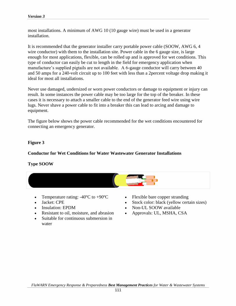
Version 3
FlaWARN Emergency Response & Preparedness Best Management Practices for Water & Wastewater Systems
111
most installations. A minimum of AWG 10 (10 gauge wire) must be used in a generator
installation.
It is recommended that the generator installer carry portable power cable (SOOW, AWG 6, 4
wire conductor) with them to the installation site. Power cable in the 6 gauge size, is large
enough for most applications, flexible, can be rolled up and is approved for wet conditions. This
type of conductor can easily be cut to length in the field for emergency application when
manufacture’s supplied pigtails are not available. A 6-gauge conductor will carry between 40
and 50 amps for a 240-volt circuit up to 100 feet with less than a 2percent voltage drop making it
ideal for most all installations.
Never use damaged, undersized or worn power conductors or damage to equipment or injury can
result. In some instances the power cable may be too large for the top of the breaker. In these
cases it is necessary to attach a smaller cable to the end of the generator feed wire using wire
lugs. Never shave a power cable to fit into a breaker this can lead to arcing and damage to
equipment.
The figure below shows the power cable recommended for the wet conditions encountered for
connecting an emergency generator.
Figure 3
Conductor for Wet Conditions for Water Wastewater Generator Installations
Type SOOW
Temperature rating: -40ºC to +90ºC
Jacket: CPE
Insulation: EPDM
Resistant to oil, moisture, and abrasion
Suitable for continuous submersion in
water
Flexible bare copper stranding
Stock color: black (yellow certain sizes)
Non-UL SOOW available
Approvals: UL, MSHA, CSA

Version 3
FlaWARN Emergency Response & Preparedness Best Management Practices for Water & Wastewater Systems
112
Conductor Capacity (Amps) for Three Phase Generator Installations
The table below provides conductor requirements for various generator sizes. Because assisting
utilities in emergency situations typically provide generators, it is recommended that a standard
#6, 4-wire power cable be used for generator installations in the 40 to 125 KW when power
cables are not supplied with the generator unit.
Table 5
Nominal Ratings for SOOW Power Cable For Generator Installations
Size (AWG) Conductor Nominal O.D. AMPS* LBS / 1000'
10 2 .615” 30 237
10 3 .650” 30 293
10 4 .700” 25 357
8 3 .835” 40 477
8 4 .930” 35 605
6 3 .975” 55 678
6 4 1.055” 45 856
4 3 1.135” 70 1030
4 4 1.255” 60 1297
4 5 1.365” 48 1400
2 4 1.455” 80 1768
Isolation of Generator from Main Power Source
The National Electric Code requires that a connected generator be isolated from utility power.
These requirements are designed to protect the installer from unanticipated line power and the
utility workers from back fed power into the utility line from the generator. Additionally, power
supplied from two sources can be out of phase and this will result in as much as double the
voltage quickly damaging plant equipment.
Main disconnect breakers should never be used to isolate power sources. They are not designed
for this purpose and can malfunction. The malfunction can fail without any visible indication.
This can be due to a mechanical failure and can go unnoticed until power is restored.
Because the plant facility will likely not have a disconnect switch, the line power must be
disconnected at the main breaker to ensure isolation. Even though line power is off due to
damages to power company wires and transmission equipment, the generator installer must
always assume that the power is active. Power can be potentially back fed from private generator
installations or could become activated by the power company while connecting generation

Version 3
FlaWARN Emergency Response & Preparedness Best Management Practices for Water & Wastewater Systems
113
equipment. For this reason it is advisable to remove the electric meter prior to making any
generator connection.
Figure 4
Electrical Connection Hook Up for Typical Control Panel
Electrical Safety Requirements
It will be necessary to physically remove the incoming conductors from the top of the breakers,
properly wrap, secure and isolate them to prevent any chance of current flow. By OSHA
standards, only a “qualified” individual can work on electrical equipment.
Electrical equipment should be checked for voltage with a volt/ohm meter prior to initiating the
connection. If voltage is detected, the line may have been energized or the voltage may be the
result of back feed and means of isolation should be initiated. In making generator connections,
the circuit should be considered live and electrical protective equipment should be worn at all
times.
After de-energizing a circuit, a “qualified” authorized individual is responsible for verifying that
the equipment has been de-energized, that electrical isolation from the main power source has
been accomplished and that the incoming power line has been capped, safely removed and
protected.
Motor Requirements

Version 3
FlaWARN Emergency Response & Preparedness Best Management Practices for Water & Wastewater Systems
114
In most cases, motor requirements at the plant facility will dictate the size of generator needed.
The table below provides values for common motor installations.
Table 6
Common Full Load Amp Requirements for Electric Motor Locked Rotor Conditions*
HP of
Motor
Single Ph
110V
Three Ph
220V
Three Ph
440V
.5 7 2.5 1.4
1 11 3.3 1.7
2 20 6 3
3 28 9 4.5
5 46 15 7.5
7 .5 68 22 11
10 86 27 14
15 38 19
20 52 26
25 64 32
30 77 39
40 101 51
50 125 63
60 149 75
75 180 90
100 246 123
* Amperes Full Load Current for Common Squirrel Cage Motors; + 10percent variation
It is important to ensure that each leg of the circuit is balanced and providing amperage to the
motor that is in reasonable proximity to the values provided.
Motor Rotation Considerations
Another issue with proper motor operation is to ensure proper rotation. In some cases the power
company may indicate the rotation at the breaker. The best method is to match the power
company’s marking with a rotation meter. However, in most cases the motor rotation will have
to be determined in the field.
Motor rotation is typically marked on the pump volute and can be observed by bumping the
motor and making an observation after generator installation. Well motors are provided with
ratcheting devices so the motor will not spin in reverse but will hum. It is important in field-
testing not to allow the equipment to rotate backwards for any period of time or damage to
equipment can occur. If building facilities with air conditioned fans are connected improperly,
damage can result.
Version 3
FlaWARN Emergency Response & Preparedness Best Management Practices for Water & Wastewater Systems
115
Motor rotation is corrected in the field by switching two connections at the breaker, making sure
that the switched circuits are not the high leg connection (see 240V Delta connection above for
this discussion.)
Use of Single Phase Generator/VFD Combination to Provide Three Phase Power
In a VFD/Single Phase Generator application, the VFD is used to convert single phase to three-
phase power fed by a single-phase generator and to efficiently match a motor/pump combination
at a lift station or a well to the conditions at the site. The use of a VFD allows water or
wastewater service to be restored to minimum acceptable levels in a most timely, efficient and
economical manner using much smaller and available generator equipment.
Centrifugal Pump/Motor Speed Relationships for VFD Control
Centrifugal pumps are widely used in water and wastewater treatment and exhibit characteristics
that make them very adaptable to variable frequency control.
Pumping equipment in water and wastewater operation will be operated at a constant speed, or
the speed provided by the motor. The variable frequency motor controller is a device that
changes the frequency of the voltage applied to the motor, which in turn changes the speed of the
motor. When the speed of the motor changes, the applied horsepower and the pumping
characteristics also change. With a centrifugal pump, these relationships are governed the
Affinity Laws. The operating conditions for a centrifugal pump may be estimated by using the
Affinity Laws. The Affinity Laws are a group of relationships that may be used for estimating
Flow, Head Condition and Horsepower requirements of a centrifugal pump when the speed of
the pump is changed from a known speed or the specific speed, to some other value.
By using these relationships a plot for all centrifugal pumps for all pumping conditions can be
developed. These relationships will be used in controlling motor speed to provide the pumping
characteristics needed in a variable speed control situation. The VFD will be used to change the
motor’s operating characteristics from a constant speed to a variable speed. Under different
speed conditions, the pump will operate at a different capacity, different head or pressure output,
and at a different horsepower. In this application, the VFD operates the motor at a reduced
horsepower.
Variable Speed Motor Control Application
The VFD can operate a motor both at a reduced voltage and reduced frequency. The same motor
will now start at approximately 150percent torque and 150percent current as compared to
600percent current for starting motors across the line and 300percent when using a soft start.
The VFD can also significantly reduce the locked rotor current because it allows the motor to
operated at a reduced speed consuming only the horsepower necessary to move the load. The

Version 3
FlaWARN Emergency Response & Preparedness Best Management Practices for Water & Wastewater Systems
116
VFD allows the motor to gradually reach a set speed that is less than the speed of the constant
speed motor under normal operation.
Again, the VFD provides a considerable advantage over conventional equipment since it starts a
motor under a reduced torque and a reduced starting current. This VFD attribute allows a small
generator to be used for smaller horsepower applications, generally below 15 HP. The limitations
on the use of a Single Phase Generator/VFD combination will be the amount of current that must
be supplied by the single-phase generator to the VFD. Generally speaking, single-phase
generators are limited to 50 amps at the single-phase breaker receptacle. This is approximately
the full load current demand required by a 10 Horsepower (HP) load under single-phase
conditions.
VFD’s can be used to operate larger than 10 HP rated loads if they are operated at reduced HP.
The advantage of a VFD is that it can be set to the HP necessary to keep the load or maintain the
minimum pumping requirements, by reducing motor speed. In these applications, the motor will
operate in this mode, until power is restored. The VFD is used to operate the motor efficiently
under at a reduced load, at a reduced HP and thus at a reduced current draw. This condition can
be found by observing check valve movement, wet well draw down or pressure conditions.
Recommended Frequency Set-up for VFD Control
The actual HP requirements will be always be dictated by the actual torque requirements (head
and pumping requirements) encountered in the field. The chart below is intended to give a good
starting point for VFD set up. Since the head conditions will typically be the controlling factor, a
good starting point for a VFD has been found to be a speed setting around 45 hertz for most
installations.
Under field conditions the VFD can be set to a minimum value of 45 hertz, and then gradually
increased until the operating speed is raised enough to fully or partially establish the required
flow by observation.
Recommendations for Sizing Single Phase Generators
It is always best to provide a generator sized larger than needed since the cost difference is
nominal but the additional power and start up capability may be needed. Field conditions may
also require full horsepower operation. The suggested sizing requirements are to multiply the HP
of the installation by 1000 and then select a generator in a range that provides at least a 50percent
safety factor. Below are some suggested guidelines. Note that some of the recommendations
show that the generator must supply to a HP less than nominal to provide a 1.5 safety factor. In
these cases the VFD would be set to a HP rating less than nominal nameplate rating on the
motor. For example in the case of a 7.5 HP motor, a 6.5 HP setting using a 10,000-watt generator
would provide a 1.5 safety factor. However, the power provided might not be enough to provide
the needed HP in the field at the lower setting. It would be much better to use a 12,500 generator
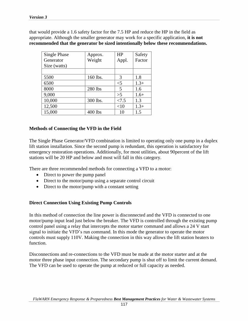
Version 3
FlaWARN Emergency Response & Preparedness Best Management Practices for Water & Wastewater Systems
117
that would provide a 1.6 safety factor for the 7.5 HP and reduce the HP in the field as
appropriate. Although the smaller generator may work for a specific application, it is not
recommended that the generator be sized intentionally below these recommendations.
Single Phase
Generator
Size (watts)
Approx.
Weight
HP
Appl.
Safety
Factor
5500 160 lbs. 3 1.8
6500 <5 1.3+
8000 280 lbs 5 1.6
9,000 >5 1.6+
10,000 300 lbs. <7.5 1.3
12,500 <10 1.3+
15,000 400 lbs 10 1.5
Methods of Connecting the VFD in the Field
The Single Phase Generator/VFD combination is limited to operating only one pump in a duplex
lift station installation. Since the second pump is redundant, this operation is satisfactory for
emergency restoration operations. Additionally, for most utilities, about 90percent of the lift
stations will be 20 HP and below and most will fall in this category.
There are three recommended methods for connecting a VFD to a motor:
Direct to power the pump panel
Direct to the motor/pump using a separate control circuit
Direct to the motor/pump with a constant setting
Direct Connection Using Existing Pump Controls
In this method of connection the line power is disconnected and the VFD is connected to one
motor/pump input lead just below the breaker. The VFD is controlled through the existing pump
control panel using a relay that intercepts the motor starter command and allows a 24 V start
signal to initiate the VFD’s run command. In this mode the generator to operate the motor
controls must supply 110V. Making the connection in this way allows the lift station heaters to
function.
Disconnections and re-connections to the VFD must be made at the motor starter and at the
motor three phase input connection. The secondary pump is shut off to limit the current demand.
The VFD can be used to operate the pump at reduced or full capacity as needed.

Version 3
FlaWARN Emergency Response & Preparedness Best Management Practices for Water & Wastewater Systems
118
Direct Connection Using Supplied Control Circuit
In this method of connection the VFD is connected to the motor input leads. A supplied control
circuit consisting of two float balls is set up in the field With this connection, only the
disconnection of the motor input leads and re-connection to the VFD is necessary.
This type of connection is preferred since the wiring is minimized. It is also recommended in
situations where lift station controls are destroyed or inoperable.
Direct Connection Using No Control Circuit
In this method of connection the VFD is connected to the motor input leads. The VFD is set to
control the motor at a reduced speed. Under this mode the motor will operate continuously.
In the direct connect to the motor/pump connection, the VFD is set at a low setting that keeps the
wet well pumped down, but supplies a continuous stream of water to the submersible
pump/motor for cooling and lubrication. A VFD controller used in this mode is the simplest of
the installation methods, and in an emergency mode following a hurricane, the VFD can be shut
off at night to conserve fuel after pumping down the collection system and restarted in the
morning when use of the wastewater collection system increases. This installation mode is the
easiest and most common type of installation of the VFD/generator combination.
This method can also be used in a rotation to service a number of lift stations or in queuing
operations where the VFD/generator is rotated, servicing the most needed lift station and then
moving to the next critical one. How the VFD/generator is used is dictated by the field
conditions and how many units can be made available.
Connecting the VFD directly to power a pump panel will not allow the VFD to be used below 60
Hz unless phase monitoring equipment is disengaged, and the VFD’s soft start will be limited.
This is not the preferred connection method although it has been used successfully in limited
applications generally where horsepower requirements are below three HP.
Steps in Making a Generator Connection
Regardless of the type of generator used, three phase or single phase, the steps in making power
connections are the same. Never rely on a breaker to provide a lock out. Breakers are not reliable
and not designed for this type of use.

Version 3
FlaWARN Emergency Response & Preparedness Best Management Practices for Water & Wastewater Systems
119
Table 7
Minimum Steps in Connecting a Generator
1. Ensure that facility operator is on-site and is knowledgeable about plant electrical
requirements. It is recommended that the plant operator start and stop plant equipment.
2. Make all appropriate generator checks. Some generators will have a breather cap that
breaks the fuel tank vacuum that must be installed prior to energizing the unit.
3. Determine power requirements and voltage from field information or from motor
nameplate(s)
4. Determine voltage configuration, i.e. Wye (120/208V) or Delta (120/240V)
5. If Delta connection, identify “high leg” and match power company position at breaker
6. Pull electric meter
7. Check that there is no incoming voltage at panel
8. Turn all breakers and equipment to “off” position.
9. Connect generator to top of incoming breaker (Note: never bypass fuses or fail safe motor
protective devices!)
10. Carefully tape all ends of wires removed at breaker including ground, to prevent
accidental energizing by power company
11. Start generator in power feed “generator feed off” position at generator breaker and allow
it to run a few minutes
12. Turn generator to “generator feed on” position
13. Measure phase to ground to check “high leg” position; reposition as needed in “generator
off” position
14. Measure phase to phase voltages for three legs to ensure voltage balance
15. Match motor rotation, if known, by switching legs while in “generator feed off” position
16. Make all generator voltage rechecks
17. “Bump” motor to determine rotation if necessary
18. Match motor rotation by switching legs while in “generator feed off” position
19. Make generator voltage rechecks
20. Turn on facility equipment to “auto position”; Note: most equipment will have delay
timers and equipment will not immediately start up.
21. Make necessary amp checks
22. Observe operation of facility equipment. In some cases it may be necessary to reset
electronic protective devices inside equipment panels
Each facility will have unique electrical requirements and it is highly recommended that a plant
operator knowledgeable about needs be on-site and participate in the generator hook-up and
powering of facility equipment.

Version 3
FlaWARN Emergency Response & Preparedness Best Management Practices for Water & Wastewater Systems
120
Generator Troubleshooting
The following are suggested procedures for checking the operation of generators before
transporting them to field locations and in performing daily maintenance checks by the party
using the generator. In emergency situations, it has been found that about 10percent of the
generators delivered to the site will not operate. Much installation delay can be avoided by
performing basic generator pre-checks before field delivery of equipment.
Table 8
Suggested Pre-Checks Prior to Field Delivery and Daily Checks at Generator Emergency
Locations
Item Problem Description/
Suggested Pre-Checks
Troubleshooting Problems
Battery Battery weak and will not start
generator.
Always start the generator and
run it before field delivery!
Check electrolyte and make sure
battery is full.
Batteries have been neglected or
have been left on trickle charges
and when the trickle charger is
removed the battery will not start
the battery will need to be replaced.
It is common for weak batteries to
discharge in the field. If
replacements are not available
sometimes daily charging is
necessary.
Oil Oil is low or a leak has
developed.
Check the oil level and make
sure that it has been filled before
field delivery.
Look for leaks at the oil pan,
drain plugs, front and rear seals
and gaskets.
All engines will consume a certain
amount of oil. Smoky exhaust is an
indication of excessive oil use or an
overfilled crankcase. Excessive oil
loss around a seal will be
noticeable. Oil should be checked
each time the generator is refueled
or more frequently if oil loss is
observed. It is recommended that
oil be left with the responsible party
at the emergency generator
location.
Coolant Coolant is low or a leak has
developed.
Fill coolant to required levels.
Check for leaks at hoses, radiator
and hose connections.
Accidental damage frequently
occurs to coolant system fins and
hoses can become brittle and
fracture resulting in visible leaks.
Sometimes radiator leaks can be
temporarily stopped using “stop
leak.” Large leaks to the coolant
system will require repair to prevent

Version 3
FlaWARN Emergency Response & Preparedness Best Management Practices for Water & Wastewater Systems
121
engine damage.
Air Filter Check for a dirty air filter.
Replace air filter as needed.
Generators are frequently operated
in dirty or dusty locations. A
clogged filter will reduce air intake
and result in high fuel to air ratios
causing rough operation and
decreased power output.
Fuel Fill fuel tank Check for leaks or water in fuel.
Generators should be refueled prior
to the tank running dry to prevent
movement of sediments and
potential water accumulations
caused by condensate. Diesel
generators may be refueled while
running but this practice is not
recommended.
Under normal operation generator crankcase oil should be replaced every 25 operating hours and
the air filter every 100 hours.
Before starting a generator ensure that the above minimum safety checks have been performed.
Crank the engine no more than 20 to 30 seconds at a time. If it does not start allow the engine to
cool two to three minutes before attempting to restart it. If it does not start after three attempts,
there are problems that must be addressed by a mechanic to avoid serious damage to the
generator.
After the generator is started, allow it to run at mid-speed for about five minutes until the oil
pressure and other gauges show proper readings. Allow partial load for a few minutes until
reaching maximum load. Never race a diesel engine.
If the generator runs and then shuts off, it indicates a fault condition. Generally a fault will occur
that is associated with one or more of the conditions listed in the above table. To avoid extensive
generator damage, more serious faults will require that the generator be shut down and serviced
by a diesel mechanic.
Generator Safety and Placement
Generators should always be placed on level ground to avoid vapor locks from forming. They
should also be placed in an unobstructed area as close as possible to the load to limit resistance
losses in the supply conductor. Generators must never be placed in an enclosed area or exhaust to
an enclosed area since the build up of carbon dioxide and toxic carbon monoxide in an enclosed
space can be fatal to people who may enter the area. Generators should always be placed in
well-ventilated areas to prevent them from overheating. Physical obstructions that block air
movement can also cause the generator to overheat.

Version 3
FlaWARN Emergency Response & Preparedness Best Management Practices for Water & Wastewater Systems
122
The generator unit can become electrically charged, proper electrical grounding of the generator
is imperative. A direct ground connection can be established by an unsuspecting person touching
metal in contact with the generator such as the generator cover standing on the ground. Without
proper grounding, this situation could be fatal.
Protection and securing safety covers provided with the generator is essential. Generator parts
become extremely hot and can cause severe burns. Children and curious by-standers should
never be allowed near generators. Where areas cannot be physically secured, they should be
marked with protective fencing or safety tape and cones where fencing is unavailable.
Generator Security
Theft of generators is another problem that occurs in emergency situations. Generators should be
safety chained at the tires to the frame to obstruct movement. Local law enforcement should be
notified to establish extra patrols in emergency locations. Any type of treatment that attracts
attention or impedes the timely movement of a generator will deter theft. Some generators are
equipped with GPS tracking devices.
Generator Fueling Requirements
The amount of time a generator runs will depend on the size of the fuel tank and the amount of
load on the generator. For this reason it is important to determine the fuel capacity of the
generator. The table below may be uses to determine the approximate fuel requirements for
generators in the 20 to 60 KW range. Generators that are operating at 50percent load will
consume about 50percent of the fuel listed for the maximum load values. It is important to
consider fueling logistics, including ingress and egress, for installed generator service personnel.
Once an emergency generator is installed, the installer must insure that arrangements are made
for fueling. In most cases the utility where it is installed will take responsibility if asked to do so.
Table 9
Fuel Consumption for Generators in Range 20 to 150 KW
Generator Size
KW Standby Use
Approximate Fuel Requirements
Gallons Per Hour @ Max. Load
Approximate Fuel Requirements
Gallons Per Day @ Max. Load
20 1.7 41
30 2.4 17
40 3.3 80
50 4.2 100
60 5.1 125
80 6.3 150
100 7.5 180
150 11.1 270
Version 3
FlaWARN Emergency Response & Preparedness Best Management Practices for Water & Wastewater Systems
123
Diesel engines develop high temperatures when working under load and should be cooled
gradually before being stopped. For this reason they should never be allowed to run out of fuel
since the extreme heat differential created by rapid shut down can damage engine components.
When shutting down a diesel engine the engine should be operated at half-throttle (no load) for
three to five minutes and then low idle for one to two minutes before shut down. In very warm
weather the shut down time should be lengthened appropriately. Diesel engines should always
be fueled to capacity to prevent condensate from forming in the tank at shut down.
When refueling a generator it is good safety practice to shut it off and allow it to cool as a safety
precaution. A fire extinguisher should be readily available to the fueling personnel. Operating
personnel should use the shut down to check the oil and coolant to prevent damage to the
equipment. It is highly recommended that generators be checked and serviced daily.
Use of Power Take Off Generator
Power take-off (PTO) single-phase generator units are available and may power by using a
tractor rated at least 30 horsepower. PTO generators may be used in the same way as a
conventional generator single-phase generator described above.
Care must be taken to ensure that the rotating shaft is within 10o of horizontal. Because of the
rotating shaft, the unit must be secured from unauthorized access.
If the single-phase power is to be converted to three phases, the VFD must be isolated from the
machine vibration.
Employees Authorized to Work on Electrical Equipment
In emergency situations there will not be enough licensed electricians available locally to
perform all the needed electrical and plant start up work. In these instances water/wastewater
utilities are frequently called upon to provide needed employees to efficiently complete the
emergency work. Since utility electrical installation work falls under OSHA requirements it is
instructive to review these requirements.
OSHA standards require employers to establish a Program and utilize procedures for affixing
appropriate lockout or tag out devices to disable machines or equipment to prevent unexpected
startup or of stored release of energy that could injure employees. The standard applies to control
of energy during servicing and maintenance or where an employee is required to by-pass a guard
or safety device or place any part of his/her body in an area where danger exists.
The standards also define affected, authorized, qualified and unqualified employees with regard
to electrical equipment. All employees must receive electrical training but only authorized
employees have received electrical training that allows them to place and remove lockouts/tags.

Version 3
FlaWARN Emergency Response & Preparedness Best Management Practices for Water & Wastewater Systems
124
Only qualified employees may work on or test energized equipment. Some larger utilities may
have established electrical training programs that provide the appropriate electrical training to
their employees that will allow them to work on de-energized equipment, including the
installation of temporary generators when the electrical line feed has been disconnected. These
utilities can be called on in emergencies to provide assistance.
Most utilities will conduct generator installation work using established crews. It is often
effective to assign workers from other utilities to these crews for assignments to fill in needed
slots or to establish additional work crews.
To ensure safety to both responder and receiving personnel all temporary service
connections should be made only under a full lock out procedure, that is ensuring a
physical disconnect from any power source that provides power to the facility.
Electrical Test Devices and Personal Safety
Generators will be installed in hazardous and wet conditions and electrical safety precautions
should be adhered to at all times to protect workers from injury.
In installing generators a volt/ohm meter, amp probe and infrared temperature meter should be
used to check voltage, continuity, amp draw and proper electrical connections. Generator
installers should be supplied with personal protective clothing including insulated gloves, eye
protection and non-flammable clothing. In making generator connections all circuits should be
considered as energized.
Connection to Line Power
After the generator has been installed line power will eventually be restored and the generator
will have to be disconnected. Since generators are frequently the property of assisting utilities,
their timely removal is often necessary. This condition presents a significant safety threat to
those unfamiliar with power company line service requirements. The figure below shows a
typical connection to a small water/wastewater utility.

Version 3
FlaWARN Emergency Response & Preparedness Best Management Practices for Water & Wastewater Systems
125
Figure 5
Removal of Generator and Reconnection of Line Power
When the generator is disconnected line power must be reconnected. Since the line power is
energized, temporary removal of the electric meter will temporarily de-energize the circuit and
allow line power leads to be reconnected to the top of the breaker without the danger of live
voltage. Connecting line power and a generator to a facility at the same time can lead to
equipment damage or a fire.
Minimum Information to Be Collected by Generator Installer
The following information is to be documented for each generator installation:
1. Utility name and physical street location of generator placement
2. Name of water or wastewater system where generator is placed
3. Utility responsible party name, title and 24 hour contact number
4. Size, owner and identification number of generator
5. Responsible fueling agent and equipment check party
6. Approximate date that the generator will be in use
7. Procedures for generator recovery
Remove Electric
Meter to
Deactivate Live
Line Power
Power Company
to Pull Line Fuse
to each leg when
Possible

Version 3
FlaWARN Emergency Response & Preparedness Best Management Practices for Water & Wastewater Systems
126
Chapter 16: Guidelines for Effective Rotation of Pumps, Generators and Tankers
Planning for Power Outages in Post Hurricane Recovery
Hurricanes in coastal communities have the potential to totally destroy the utility infrastructure.
However, in most cases the water/wastewater utility can expect about 80 percent to 90 percent of
the total utility system to be out of power immediately after a major hurricane event. Power
outages will be widespread and in most areas will be out for several days for Category 3 and
smaller storms and several days to several weeks for Category 4 type storms. In Category 3 type
storms away from coastal devastation, 70 percent of the main electrical feeders will be up within
four days. During this period the utility system will be severely stressed and auxiliary power or
other means must be provided to ensure adequate water and wastewater service to customers.
Power Company Restoration Coordination
All power companies maintain a priority power restoration plan. Knowing the circuit number
that feeds a water/wastewater facility can greatly improve the knowledge of when the facility
power may be restored.
Additionally, water/wastewater facilities that serve critical facilities such as emergency
operations centers, hospitals, and dialysis centers can receive higher priority restoration by
informing the power company of power needs for restoration of service.
The table below illustrates a typical power company restoration schedule.
Priority 1 Feeder Circuits
Critical Facilities, hospitals, government and public
safety
Priority 2
Feeders and Branch Circuits
Facilities that are not critical but important
Priority 3 Feeders and Branch Circuits
Residential and Commercial Customers by number
effected
DEP Emergency Power Backup Requirements for Water Systems

Version 3
FlaWARN Emergency Response & Preparedness Best Management Practices for Water & Wastewater Systems
127
Each community water system (CWS) serving, or designed to serve, 350 or more persons or 150
or more service connections shall provide standby power for operation of that portion of the
system’s water source, treatment, and pumping facilities necessary to deliver drinking water
meeting all applicable primary or secondary standards at a rate at least equal to the average daily
water demand for the system. Standby power is required to be provided through:
Connection to at least two independent power feeds from separate substations; or
One or more auxiliary power sources (i.e., generators or engines).
Where power is provided by auxiliary power feeds, it is likely that both feeds will be down in the
event of a serve hurricane.
Where standby power is provided, an in-place auxiliary power source is preferred. A portable
auxiliary power source may be provided only if all of the following conditions are met:
Where the time delay required to manually transfer electrical loads from one power
source to another could result in failure to maintain the minimum water distribution
system pressure required
The supplier of water demonstrates that the water system has first priority for use of
the portable auxiliary power source.
The supplier of water demonstrates that the portable auxiliary power source will at all
times be in reasonably close proximity to (i.e., within 25 miles of) the water system
components for which standby power is required
In the event of a serve storm all of these situations could be disrupted.
DEP Requirements for Permanent Generators at Lift Stations
Emergency generation requirements for lift or pumping stations are found in FAC 62-
604.400(2). The rules require that emergency pumping capability be provided for all pump
stations. Pump stations that receive flow from one or more pump stations through a force main or
pump stations discharging through pipes 12 inches or larger shall provide for uninterrupted
pumping capabilities, including an in-place emergency generator.
Lift stations that receive flow from more than one or more lift stations or pump into a force-main
12” or larger, are known as master lift stations for the purpose of conducting a lift station
analysis.
DEP Emergency Generator Requirements for Non-Master Lift Stations
For non-master lift stations, emergency pumping capability may be accomplished by connection
of the station to at least two independent utility substations, or by providing a connection for

Version 3
FlaWARN Emergency Response & Preparedness Best Management Practices for Water & Wastewater Systems
128
portable or in-place engine-driven generating equipment, or by providing portable pumping
equipment.
Emergency Generator Alternatives for Non-Master Lift Stations
According to DEP requirements all lift stations that do not provide auxiliary power described
above must provide one or more of the following:
• Emergency generator transfer switch that allows for a direct generator connection
• Pump-around, or allowance for direct connection of portable pump
• Use of tanker trucks for transport of wastewater
Performing a Water/Wastewater Power Requirement Inventory
Identifying the power requirements of water and wastewater facility equipment is the first step in
the development of a plan to supply power using generators. Although all water and wastewater
facilities require this analysis, an example of a typical lift station inventory is provided here as an
example.
Development of a Lift Station Indexing System and Identification of Lift Station Attributes
The first step is preparing a location index for storing of pertinent lift station attributes. The
location and name convention allows the utility to quickly locate the effected facility.
A typical lift station indexing system is illustrated below:
Typical Lift Station Indexing System

Version 3
FlaWARN Emergency Response & Preparedness Best Management Practices for Water & Wastewater Systems
129
Developing a Lift Station Attribute File
A lift station attribute file is a file that contains pertinent information about a lift station that is
necessary for emergency power restoration. A typical summary of suggested lift station attributes
is illustrated in the following example.
Courtesy of Gainesville Regional Utilities

Version 3
FlaWARN Emergency Response & Preparedness Best Management Practices for Water & Wastewater Systems
130
In this example, the lift station number, its name, the address location, the priority for restoration,
circuit and electrical servicing information, the place that the lift station pumps to, the flow
received from other lift stations and collection systems and any special emergency by-pass
provisions such as permanent generator on-site, existence of a quick connect generator
receptacle, pump around capability are all documented.
Performing a Lift Station Assessment
Wastewater utilities depend on a reliable source of electric power for running pumps at lift
stations. Many mid to large size utilities have from a few hundred to several thousand lift
stations in operation at any one time. Typically, these power loss needs are met by installing
portable generators, which have been borrowed from assisting utilities. The need to efficiently
dispatch generators to affected areas impacted by hurricanes must be based on criteria that ensure
the distribution of generators to optimally supply power to the most significant number of lift
stations and impacted utilities. A lift station assessment may be used to estimate utility needs
based on the number of lift stations and the horsepower used.
Performance of a Lift Station Assessment
A Lift Station Assessment analysis assumes emergency conditions where a complete loss of
power occurs for an extended period exceeding three days. The analysis assumes that lift stations
that utilize pumps 20 HP and smaller are of the duplex variety. A duplex lift station is a lift
station that includes two pumps, with one pump designed to handle incoming flow with the other
pump out of service.
The analysis considers that in an emergency situation a lift station smaller than 20 HP (uses two,
20 HP pumps) can handle incoming flow for an extended period of electrical outages with an
emergency generator using only one of the two pumps available at the station or in some cases
has wet well capacity that can be used for storage allowing generators and other equipment to be
used to evacuate wastewater in a rotation.
The numbers developed in this example are conservative and for most systems the number of
generators that are required following a hurricane and long-term power outage can be reduced
further.
No attempt has been made to equate these numbers to any specific wastewater system. If such a
comparison is to be made it is necessary that the utility system prepare similar tables to those
provided in this document.
Table 1: Lift Station Assessment Analysis Based on Number of Lift Stations and
Horsepower at each Station
The following table illustrates the lift station distribution for a typical mid-sized utility.

Version 3
FlaWARN Emergency Response & Preparedness Best Management Practices for Water & Wastewater Systems
131
Size of Pump
Unit (HP)
Number of
Lift
Stations in
Category
percent of
Entire
System for
Lift
Stations
Rolling
Average
percent
Number
of
Perm.
Gen.
Rolling
Average
Perm. Gen.
0 to 5 HP 57 37percent 37percent 0 06percent
7.5 HP 1 1percent 38percent 0 11percent
9.4 & 10 HP 46 29percent 67percent 1 11percent
15 HP 3 2percent 69percent 1 15percent
20 HP 32 21percent 90percent 1 14percent
30 to 40 HP 5 3percent 93percent 1 35percent
47 HP 10 6percent 99percent 4 42percent
Above 50 HP 2 1percent 100percent 1 50percent Courtesy: Gainesville Regional Utilities

Version 3
FlaWARN Emergency Response & Preparedness Best Management Practices for Water & Wastewater Systems
132
The numbers in bold are a rolling average from the smallest station to the largest. The numbers
in italics are a rolling average from the largest system to the smallest. From the above table
several facts can be discerned:
1. Approximately 90percent of the system consists of duplex lift stations that use 20 HP and
smaller pumps.
2. Only 10percent of the system (17 stations) consists of lift stations that require generators
that are larger than 30 KW.
3. Of the 17 lift stations that are larger than 20 HP, 6 have permanent generators at the lift
station site. If we were to include 6 portable generators, then 71percent or 12 of 17 lift
stations that use 30 HP pumps and above would have auxiliary power in an emergency
situation.
Performance of a Lift Station Assessment Analysis is essential in determining the need and size
of three phase generators in the aftermath of a significant storm. This analysis provides
information critical in determining the most effective method of initiating short-term operation.
Another analysis that must be performed is to determine the number of lift stations that receive
flow from other lift stations. This fact is important because DEP regulations require that
emergency pumping capability be provided for all these pump stations.
This can be in one of three forms, emergency generator transfer switch that allows direct
generator hook up to a receptacle, provision of a “pump around,” that is a connection point that
allows a portable pump to discharge from the wet well directly into the pump station discharge
main or for the provision of manual transfer that is the use of tank trucks that can use either
portable and/or mounted pump and suction hose to evacuate wastewater from the wet well in a
manner fast enough to avoid a spill or a back-up into a private residence.
Determining Pumping Rate and Critical Wet Well Storage Rate
Determining Wet Well pumping and fill rates can be determine by performing a draw down test.
Knowledge of pumping rate and refill rate is critical in establishing lift station restoration
priorities. The information is invaluable in establishing lift station relief rotation schedules for
servicing lift stations when insufficient numbers of generators are not available.

Version 3
FlaWARN Emergency Response & Preparedness Best Management Practices for Water & Wastewater Systems
133
Setting Critical Wet Well Storage Volume Pumping Priorities
Once wet well pump rates and refill rates have been determined these rates can be used for
establishing service rotation priorities. An example is illustrated below. Note that even though
Master Lift Stations may have long fill rates they are always considered a top priority in a
rotation because of the amount of wastewater that can be accidentally discharged to the
environment.
Classification Category Priority
Master Stations Critical 1
Establish Categories
0 to 45 minutes Critical 1
45 minutes to 2 hours Semi-Critical 2
2 to 4 hours Semi- Stable 3
4 to 12 hours Stable 4
Lift stations with semi-stable to stable conditions are typically found in subdivisions and can be
left for long periods of time without concern for overflows. These types of lift stations are prime
candidates for servicing by rotation using a combination of generators, pumps, water tankers and
pumper trucks. In a rotation method, lift stations may be serviced using existing forcemain
connections and/or transporting wastewater to other lift stations that are operational.

Version 3
FlaWARN Emergency Response & Preparedness Best Management Practices for Water & Wastewater Systems
134
Selection of Equipment for Servicing Lift Stations by Rotation
The guidelines below illustrate proper application of equipment for lift station failure.
Three Phase Generators
Master Lift Stations
> 15 HP
> 1 Pump Required
Single Phase Generator/VFD’s
Residential Lift Stations
< 15 HP
1 Pump Required (Duplex Lift
Station)
Portable Pump/Tankers (5000 to
10,000 gallon variety)
•Broken Forcemains
•All Size Stations
•Filling Large Tankers not
equipped with pumps (Nurse
Trucks)
Pumper Trucks (1000 to 3500
gallon variety)
•Residential Lift Stations
•Close Proximity
•Access to Close by Disposal
Point
This equipment can be used effectively in a service rotation basis after service priorities and wet
well fill rates have been established. Generator and pumper truck rotation is sometimes called
“hopping” and greatly reduces the number of generators needed by a utility.
In this mode a generator and/or pumper truck moves from lift station to lift station evacuating
the wastewater from the wet well and moving on to the next lift station. This mode can be very
effective because in many cases smaller lift stations (5 HP to 10 HP) have sufficient storage
capacity to be left without power overnight without spilling. Daily routes are set according to
wet well storage fill rates.
Lift Station Rotation, Hopping and Queuing
Lift station rotation is a method used to move from lift station to lift station in a repetitive and
prescribed pattern using a generator sized for the horsepower requirements of a specific group of
lift stations. Hopping refers to using multi-equipment to effectively evacuate wastewater based
on fill rate considerations. Queuing refers to servicing lift stations based on the most critical to
the least critical station as conditions change during the day. In most cases, a combination of all
of these methods will be used in restoration activities for a medium or large utility.
The following are recommendations for set up of servicing lift stations by the hopping method.
Version 3
FlaWARN Emergency Response & Preparedness Best Management Practices for Water & Wastewater Systems
135
Developing a Transport Model for Pumper Truck Hopping
Define Variables, i.e., number of pumper trucks available (4 max. manageable), size of
transport tank, number of critical and semi-critical stations, distances to disposal point
and fill and empty time (generally 15 minutes each.)
Define transport routes, i.e., routes in miles from lift station to disposal point, travel time
(assume ~ 30 MPH)
Develop Transportation rotation plan for pumper trucks
Record information and make field adjustments
Developing a Transport Model for Generator Hopping
Define Variables, i.e., number of pick-up trucks available, size HP of Lift Stations,
number of critical, semi-critical and stable stations, provisions for electrical connections
and pump down time
Define transport routes, i.e., routes in miles from lift station to next lift station. Generally
will use queuing method (most critical to next most critical), and travel time (assume ~
30 MPH)
Develop Transportation rotation plan
Record information and make field adjustments
Smaller generator units can be deployed in a timely manner after a storm since they are more
available and easier to transport and maneuver in tight spots. Use of small generators also frees
up larger three phase units for deployment to priority areas.
Considerations for System Using Low Pressure Collections Systems
Low Pressure Collection Systems
Collections system with wastewater customers that use individual electrically powered STEP,
grinder and vacuum technologies are called low-pressure to differentiate them from gravity
sewer and force main systems. Although STEP and vacuum technologies use low or negative
pressures, grinder pumps typically operate at the same or higher pressures that are found in force
mains.
Pumping Requirements and Loss of Power for Low Pressure Systems
All low-pressure technologies rely on power being supplied to each location and when the power
is interrupted the ability for the individual residence to empty on-site tankage. These systems
typically have a central collection basin (lift station or vacuum station) for repumping into the

Version 3
FlaWARN Emergency Response & Preparedness Best Management Practices for Water & Wastewater Systems
136
force main system. If the power outage extends over the entire area and a long duration, then the
central collection basin also cannot function.
The typical simplex grinder system is a single pump system operating on 230 volt, single-phase
electrical power, in a 3-foot diameter, 4-foot deep fiberglass basin. The simplex system is used in
applications where the wastewater flows are 250 gallons per day or less. Grinder pumps are
typically specified as follows:
Submersible type pump motor
2-horsepower at 3450 RPM
Single phase, 230 volt, 60 Hertz
Centrifugal design with grinder assembly
Average flow - 35 gpm at 51 TDH
Minimum flow - 10 gpm at 83 TDH
Maximum flow - 43 gpm at 18 TDH
Emergency Operation of Low Pressure Systems
Strategies for emergency operation of Low Pressure Systems for long durations include
conservation strategies to minimize volumes, use of portable generators, use of pump outs using
tanker trucks and setup of portable wastewater facilities (Porta-Potties.)
Notification to Homeowners to Conserve Water
Notifying customers that they have limited storage capacity in their wastewater system should be
a first step following an emergency. They should use no more than 10 to 15 gallons of water per
day until power is restored. Assuming that most individuals don’t shower with cold water, the 10
gallons per day should handle most sanitary functions and gray water could be disposed of
separately. It goes without saying that customer education before the situation would be
beneficial.
Pump Outs Using Tanker Truck Servicing
Utility systems may wish to have provisions for pumping on-site tankage to relieve customer
backups in their emergency plans. Utility systems can put in place service contracts with local
septic tank pumpers – some systems have opted to purchase pumper trucks for normal low-
pressure system operation and emergency situations.
Emergency Power Generation for Low Pressure Systems
Customers may prepare for power outages by supplying emergency power generation. The
power needs for each system will vary by size and capacity of pumps. It is recommend that
Version 3
FlaWARN Emergency Response & Preparedness Best Management Practices for Water & Wastewater Systems
137
generators should be at least twice the total horsepower requirement. Given that one horsepower
is equivalent to 1.34 kilowatts, it would seem easy to quickly estimate power generation needs,
but startup power, power factors, and lost amperage through wires need to be taken into account.
Generators tend to run longer, use less fuel, and overheat less frequently if they are taking a
lower load. Generator sizing for low-pressure systems are estimated as flows:
STEP Systems – 1000 to 1,500 watts
Grinder Systems – 3,000 to 10,000 watts *
Vacuum Systems – 250 watts
* Note: Some grinder pumps can pull up to 10,000 watts (or 50 amps) at start-up but may run
on less than 3,000 watts (2.8 kVA). Homeowners may be able to keep ahead of wastewater if
they run the pump for short periods of time and only as needed.
Portable Sanitary Facilities
Utility systems may wish to have provisions for placing portable sanitary facilities for areas
served by low-pressure systems. Utility systems have put in place service contracts with local
suppliers for emergency situations.

Version 3
FlaWARN Emergency Response & Preparedness Best Management Practices for Water & Wastewater Systems
138
Chapter 17: Development of Exit Strategies for Responders
Providing Restoration Assistance through the FlaWARN Network
The purpose of the Florida Water and Wastewater Agency Response Network (FlaWARN) is the
timely restoration of essential water and wastewater service to impacted populations. Generally,
these response activities are intended to be short-term. In most cases restoration will consist of
restoring temporary power and making the repairs necessary to render facility equipment
operational.
Requirements for the Use of Prudent Response Procedures
In an effort to protect public health and the environment, assisting utilities will use prudent
response procedures to restore essential potable water and wastewater functions. Further, efforts
will be made to restore equipment at water plants, wastewater plants, and assure water quality
and quantity. These repairs should be completed using many of the BMP’s described in this
document. In some cases unconventional repairs may be necessary to restore service quickly
pending more permanent repairs. The purpose of a responder is to restore service in a safe and
reliable manner, as soon as possible and/or to protect the environment from contamination.
Longer-term reconstruction and repairs to the water and wastewater systems are the
responsibility of the damaged utility. In the long-term, the damaged utility should secure the
contractors, equipment, materials, etc., necessary to return the system to its normal condition.
Considerations for Responder Utility Personnel
In an effort to restore service in a timely manner, the assisting utilities may be expected to arrive
ASAP. In an attempt to restore service efficiently and effectively, they may be expected to work
long hours and extended workweeks under very adverse eating and sleeping conditions. For
longer-term responses, work crews may need to be rotated in and out of the damaged area to
keep workers alert, productive, and safe. An additional priority is getting the assisting utility
workers back home where their normal workload is being performed by other utility employees,
and to their families who may have needs of paramount importance.
Completion of Restoration Activities and Exit of Responder Agency
Once water service (including quality, pressure and quantity) along with wastewater service
(including collection, pumping, treatment and disposal) can be confirmed, the damaged utility
has the obligation to maintain the operation. Response activities are not normally intended to
provide long-term replacements for utility employees, unless there is an agreement and/or a
demonstrated need to do so. Before departing, the responding crews should make arrangements
with the assisted utility for fueling, lubrication, and standard equipment checks. Also necessary
are provisions for safekeeping of equipment when it is no longer needed and agreements

Version 3
FlaWARN Emergency Response & Preparedness Best Management Practices for Water & Wastewater Systems
139
beforehand on whether the equipment can be moved by the damaged utility to other locations.
When these arrangements are made, the responding utility can return home.
Determining the End Point of Responder Assistance
It can be difficult to judge when a responder utility’s work is finished. The most obvious
measure is when power has been restored to the impacted facility. Once power is restored it is
imperative that temporarily loaned equipment be disconnected and moved to areas where power
may still be lacking or returned back to the lending agency. Restoration of power is indicative of
a condition where permanent repairs to equipment can be initiated by the damaged utility.
Reconstruction work requests are a frequent issue and it was not the intent of FlaWARN to assist
damaged utilities with these needs. Normally, the assisting utility will not remain at the
damaged utility to do reconstruction, long-term repairs and recovery, or infrastructure
installation. These types of long-term improvement responsibilities were not contemplated as
part of the Mutual Aid Agreement and are better handled by private contractors who are licensed
to do this kind of work.
For example if a damaged utility asks the assisting utility to install two and a half miles of water
main to improve water service in an area of the community, this is a clear signal that the
response phase has ended and the repair and reliability improvement phase had begun. It is best
if the crew leaders from both damaged and assisting utilities communicate early and often in the
response process as to restoration goals, including what has been achieved and what remains to
complete the response. The goal should always be to place the system in a condition where the
damaged utility can manage it.
It should be noted that rarely do the responders or responding utility crews ask to go home or
leave the damaged utility. In less than one day, the responders may become fully invested,
attached, and committed to the response effort. Because of the dire situation, the responding
workers are going to work as hard as they would or harder than they do at their own system.
They naturally want to stay and alleviate any suffering they can for the damaged utility and
community. It is also natural that damaged utilities will want to keep good responders around as
long as possible, once their abilities have been demonstrated.
When an assisting utility returns home the damaged utility may still need equipment, like
generators and by-pass pumps. If the assisting utility is willing to leave behind any equipment
the BMPs on loaning equipment should be followed.
Besides operating, maintaining, repairing, and safeguarding the equipment, the damaged utility
should coordinate with the assisting utility to return the equipment and any accessories ASAP, in
at least as good condition as it was received. If the equipment can be spared until operations
return to normal at the damaged utility location, it is appropriate that the damaged utility return
the equipment to the assisting utility instead of relying on the lending utility to come get it or
make arrangements for its return.

Version 3
FlaWARN Emergency Response & Preparedness Best Management Practices for Water & Wastewater Systems
140
When transporting equipment to the home location, the assisting utility should check all vehicles,
trailers, tires, rigging, and equipment to ensure security, safety and proper working condition for
the return trip home. Also, remember the need to accommodate what will likely be a very tired
crew. The returning crews may need to be reminded to take great care when returning home,
make frequent stops and driver rotations, and secure lodging if needed to prevent potential
accidents and unnecessary risk from fatigue. At all times CDL regulations and posted traffic
speeds should be adhered to, so as not to endanger the public.
Need for Debriefing of Responder Personnel
Once the assisting utility returns and the responders are rested, a debriefing meeting should be
held to share experiences and insights to benefit future responders. The debriefing aids the
assisting utility, helping them analyze and improve their Emergency Preparedness and Response
Plan. Every response opportunity will provide learning experiences that can be used to increase
effective operations at home and in the field.

Version 3
FlaWARN Emergency Response & Preparedness Best Management Practices for Water & Wastewater Systems
141
Chapter 18: Flood Preparation and Response
General Discussion
Recent hurricane and other climatic events support a conclusion that more severe flooding
conditions than previously experienced or predicted may occur. These flood problems may be
exacerbated in communities where development has altered the natural buffering affects such as
wetlands or woodland area that previously had higher levels of water retention and infiltration.
Additionally, conditions that support build up antecedent wet conditions intensify floods and
may produce floods of significantly high reoccurrence frequencies that have not been
anticipated. Since hurricane flood surge strength is generally not predictable to a specific
location and that flash floods give no warning of their intensity, new provisions are suggested to
protect utility facilities that have not been used in the past.
Procedures for Operation of Flood Threatened Water and Wastewater Facilities
Importance of Maintaining Water Treatment and Distribution Pressure
Positive water pressure provides the major source of protection from microbial and chemical
contamination of the water system and from the intrusion of rocks, stones and silt that may be
difficult if not impossible to remove. Water pressure also provides the primary means of fighting
fire for many municipal systems. Thus maintaining water pressure before, during and after a
flood should be the top priority and protection and response efforts should be planned
accordingly.
If positive pressure cannot be maintained in flooded sections of pipeline, these sections should be
isolated by turning off valves in such a manner to protect the remainder of the water system.
Often the biggest threat to water treatment is the loss of the ability to backwash using
conventional gravity methods. In these instances, sandbags may be used to direct backwash
water out the top of tanks to open areas away from plant structures.
In instances where well capacity is threatened temporary connections to nearby communities
through fire hydrants using pumps or pumper trucks is often employed.
It is not recommended that contaminated water be introduced into a water supply system for any
purpose since the water will likely render the system inoperable for public supply in the future.
Importance of Wastewater Treatment
Wastewater Plants are often at the lowest points in a drainage basin and plant processes are often
inundated in severe flooding situations. The loss of a wastewater plant in the buildup of
hydraulic pressure upstream can result in the popping of manhole covers that then allow for
inflow of surface water. Wastewater plants also provide a central area for collection and disposal

Version 3
FlaWARN Emergency Response & Preparedness Best Management Practices for Water & Wastewater Systems
142
of wastewater and loss of treatment moves spills to areas that may not have equivalent capacity
of dilution and movement of partially treated wastewater downstream.
Common problems with wastewater plants are in the preliminary treatment area, especially the
bar screens. Sticks, rags, rocks and other debris will be carried to these units and they can be
quickly overcome. Flow conditions will often prevent repairs that can quickly result in sewage
inundating other plant processes and buildings. To prevent this occurrence, many plants have a
separate small generator that can operate preliminary screens and grit removal processes in a
power outage.
The importance of grit removal is another issue that wastewater treatment plant operators must
address. Flood conditions will cause both inflow and infiltration to significantly increase forcing
large amounts of sand and grit into the collection system. Many times grit facilities will see a
500% increase in the amount of this material that is being collected. Loss of grit removal
facilities can result in treatment capacity being severely impacted by the introduction of grit into
treatment basins and its deleterious affects on pumps used in the plant treatment process. Grit
removal facilities should thus be kept running.
Hydraulic flows into wastewater plants under severe flooding conditions can be 3 to 4 times the
average daily flow rates. These hydraulic flows can wash needed bacteria out of the plant
adversely impacting treatment. During flood conditions wasting of sludge should be suspended
to conserve bacteria needed in the treatment process.
Controlling inflow and infiltration is another operating concern under flooded conditions. Low
lying or inundated mobile home parks are often a contributor of these problems. Thus it is
incumbent on the wastewater plant manager to plug open drains in these parks before the
flooding hits. After the flooding hits flow from mobile home parks that are underwater are often
shut off to prevent large surface water intrusions.
Streambank erosion is another problem that operators face in storm flow conditions. Meandering
streams often dislodge pipelines allowing for direct inflow of surface water. Knowing where
these locations are and protecting pipelines with rip-rap are the best policy. It is difficult if not
impossible in some cases to find open pipelines taking in inflow. If necessary they can be found
by swirling vortexes and plugged by sinking materials to slow the inflow to smaller volumes.
After each major storm all manholes and pipelines in flood prone areas should be inspected for
inflow and infiltration.
Water Tanks and Chemical Storage
Water tanks of any sort should be topped with water before a server storm to prevent floating.
Likewise chemical storage tanks that are empty should be filled with water and their contents
pumped to other tanks.
It is not a good idea to attempt to secure empty tanks to floor slabs since the tank may float the
slab if inundated.

Version 3
FlaWARN Emergency Response & Preparedness Best Management Practices for Water & Wastewater Systems
143
Planning for Pre-flood Events
Pre-flood activities include actions that identify flood prone areas where utility infrastructure is
located and include relatively low cost improvements that provide higher level of protection than
would normally be considered.
These activities include:
Flood risk management identification
Pre-flood mitigation efforts
Improved Forecasting
Development of Triggers for Initiation of Response
Flood Mitigation and Critical Facility Identification:
Flood Management identification targets critical facilities that are located adjacent to rivers and
water impoundments used for flood management. Methods to identify these facilities can be
made facilitated by the review of basic FEMA flood maps and use of SLOSH Models to
determine the likelihood of flooding. Facilities are then identified and targeted in these areas and
are then ranked by their importance in continuous utility operation. Major facilities such as
production wells, water and wastewater treatment plants and major lift stations are targeted as
primary candidates for flood mitigation actions even though they may be protected for a 100 yr.
event. Where high water marks on fences or buildings have been observed at particularly higher
levels from rainfall events over the past 5 to10 years than previously recorded, these should be
used as references for events that are likely to be exceeded in the near future.
Targeted Pre-Flood Mitigation Actions
Unlike most conventional program for flood mitigation where structures are protected by on
historical rainfall and flood events, flood mitigation does not include a risk assessment as the
primary driver. This is because the probability of the event can not be reasonably determined
from past history. The analysis is performed on two factors. The importance of the facility in
providing continued operation of water or wastewater service and the facility’s proximity to
water bodies that may reach water levels that are beyond those predicted are the primary criteria
used in the initial screening.
Determining the mitigation approaches are then developed by asking the following questions in
three different categories, Major Construction Activities, Minor Construction Activities and Pre-
flood Construction Activities:
Major Construction Activities
Are the dikes or berms that are in-place contiguous and can they function
at higher elevations by relatively minor filling or build up of surrounding
ground?

Version 3
FlaWARN Emergency Response & Preparedness Best Management Practices for Water & Wastewater Systems
144
Are the existing dikes, berms or other structures adequate to withstand
erosion that may be caused by changes in velocity and higher water levels
and can they be strengthened by the addition of rip-rap or other erosion
control measures?
Where construction of physical barriers and raising of protective
separations are not feasible, can a smaller area be protected with a
cofferdam built around the facility?
Can provisions be made to use existing block buildings as protection by
sealing off doors, window vents or louvers?
Minor Construction Activities
Can on-site transformers and motor controls be raised to elevations at least
3 feet higher than the predicted 100 yr flood?
Can motor control panels and SCADA panels be raised to at least 3 feet
higher than predicted by a 100 yr flood?
Can a pump be permanently mounted in a dry area to allow for pumping
floodwaters away that might enter the building under extreme conditions?
Can floor drains be plugged and water under pressure be evacuated from
the building by makeshift piping?
Can any of the construction activities listed in the major construction
activities above, be accomplished by the use of sandbags or permanent
concrete slabs?
Pre-Flood Response Activities (these actions should be taken when the actions above were
not implemented or are unlikely to prevent flooding)
Disconnecting and Raising Electric Motors to above flood stage and
providing quick disconnects (accessible electrical connections to motor
pigtails to facilitate movement)
Disconnecting and removing SCADA equipment especially UPS type
units that will damage submerged equipment
Proper Placement of Sand Bags for Flood Protection
Sandbags are often used to protect structures and equipment from floodwaters and their
proper placement can be invaluable in a flood event. Sandbags are used for protection of
buildings and other structures near creeks or lakes and in similar situations where water is
rising with little or no current. They may also be placed to divert flowing water away
from structures.
General Sand Bag Construction
The use of sandbags is a simple but effective method of preventing or reducing damage
from flood water and/or debris. The following procedures should be used in constructing
sandbag protection:

Version 3
FlaWARN Emergency Response & Preparedness Best Management Practices for Water & Wastewater Systems
145
Close-weave burlap bags are recommended for all sandbag construction.
Fold over the empty top of the bag in a triangle to keep sand from leaking.
Place each bag over the folded top of the preceding bag and stomp into
place before placing the next layer of bags.
Stagger the second layer of bags, stomping each bag into place before
placing the next.
Stomp each succeeding layer of bags.
Protecting Structures
Lay plastic sheeting on the ground and up the building walls to a point at least one
foot above the predicted water elevation, and far enough out on the ground to
form a half pyramid of sandbags. Secure plywood over doors and vents. Overlap
plastic sheeting and sandbags at corners of buildings.
Protecting Slopes
The "raincoat" method is used to prevent further saturation of levee or hillside
slopes. Plastic sheeting is laid out flat on the slope, and stakes are driven into the
ground just above the area to be protected. The stakes are four feet apart with a
one-foot stagger. The plastic sheeting is secured to the stakes with tie-down
buttons or small round rocks and rope.
Placing Sandbags
Protecting Structures

Version 3
FlaWARN Emergency Response & Preparedness Best Management Practices for Water & Wastewater Systems
146
Stockpiling Sand for Filling Sandbags
Materials required for 100 lineal feet of sandbag wall
Height above ground Bags required Cubic yards of sand
1 foot 600-800 10 to 13
2 feet 1400-2000 23 to 33
3 feet 2200-3400 37 to 57
4 feet 5300 88
5 feet 7600 137
6 feet 10000 167
Flood Monitoring and Prediction
Floods are generally divided into three categories based on the utility’s ability to prepare and
respond. These categories are Storm Surges which occur in coastal ocean areas, Flash
Floods caused by local or regional unusually high rainfall intensities and River Flooding
caused by significant periods of moisture coupled with moderate to intense rainfalls over
long durations. These categories my overlap but can generally be used for setting targets to
initiate the response.
Flood and Hurricane Warnings are given by the National Weather Service and NOAA
Weather Radio. Flood alerts are given according to the following descriptions:
Floods (Can Take Several Hours to Days to Develop)
A flood WATCH means a flood is possible in your area.
Sandbag Information Courtesy:
Sacramento County Dept. of Water Resources
Slope Protection

Version 3
FlaWARN Emergency Response & Preparedness Best Management Practices for Water & Wastewater Systems
147
A flood WARNING means flooding is already occurring or will occur soon in your
area.
Flash Floods (Can Take Only a Few Minutes to a Few Hours to Develop)
A flash flood WATCH means flash flooding is possible in your area.
A flash flood WARNING means a flash flood is occurring or will occur very soon.
Storm Surges
Storm surges are a phenomenon of hurricanes that are a danger to coastal utilities. These types of
events often have several days of warning allowing the utility to prepare. The predicted impact of
the expected storm surge is provided by the National Weather Service.
The extent of the surge is related to the position of the high tide at the time of hurricane landfall.
In this type of flooding, the water surge is accompanied by very strong winds and the
combination of wind and saltwater that inundates utility facilities will like destroy them
completely. Physical protection of electrical components is the best form of protection.
Generally for any hope of recovery after saltwater inundation, motors must be kept wet to keep
salt from drying out and special procedures must be used to remove saltwater that must be
incorporated immediately after the flooding. Recovery techniques for saltwater damaged motors
are included in the Appendix. Generally, electrical panels damaged by saltwater will not be
salvageable and replacement will be necessary.
Flash Floods
The National Weather uses Doppler radar to predict flash floods. Doppler radar is accurate to
the street level. This ability allows the Weather Service to provide more accurate flash flood
warnings.
Flash floods will typically occur within a couple of hours and thus adequate response time
will not be available to a utility. Like any flood threat the best approach is physical protective
measures.
Motors and controls submerged in fresh water can sometimes be restored if response is
timely. Procedures for restoring control panels and motors are found in the following section.
River Flooding
In general, river flooding is predicted by establishing the likely peak elevation (flood crest)
reached by a river by the National Weather Service. Under normal conditions river flooding
can be predicted several days in advance. Where antecedent moisture conditions are high and
localize rainfall is predicted to heavy and continuous, river flooding may quickly change to a
flash flood.

Version 3
FlaWARN Emergency Response & Preparedness Best Management Practices for Water & Wastewater Systems
148
River flooding generally allows for protective sand bags to be placed around structures to
provide dry areas for the continued operation of transformers, motor controls and motors.
Where buildings are protected with sand bags, provisions must be provided to remove water
that will accumulate when the outside water level exceeds the building slab elevation. This
will include water which may backflow through floor drains, and electrical conduits or flow
through fan louvers or under doorways. An assessment of
protective flood measures to prevent seepage, inflow and leaks must be undertaken. A
method of pumping water out of structures must be included in any flood protection plan.
Preliminary Flood Condition Assessment
Unlike preliminary assessments on facilities that have been damaged by high wind which are
performed immediately after a hurricane, flood water damage occurs from the immediate
post flood conditions, conditions that may deteriorate immediately after a flood and the
longer-term post flood threats that continue.
Flood condition assessments identify current damages, current threats and future threats.
Depending on the severity of the event, these are categorized as: forecasting, detection,
assessment, warning and response. In the preliminary flood damage assessment phase
recovery and mitigation are both addressed and reconstruction, flood defense and recovery
are all included in the assessment.
Completing the Flood Condition Assessment Form
The purpose of the Flood Condition Assessment Form is to for providing the following
information:
1. Providing a visual record showing site inundation, the scope of the flood damages and
the possibility of potential flood damage that can be mitigated. This is best done
through annotated photographs, sketches and measurements taken before the cleanup
and restoration activities actually begin.
2. Create an inventory of equipment damages to transformers, electrical control panels,
electric motors and chemical dosing equipment.
3. Use the gathered information to prioritize restoration plans and initiate corrective
actions of stabilization, mitigation, repair, and restoration.
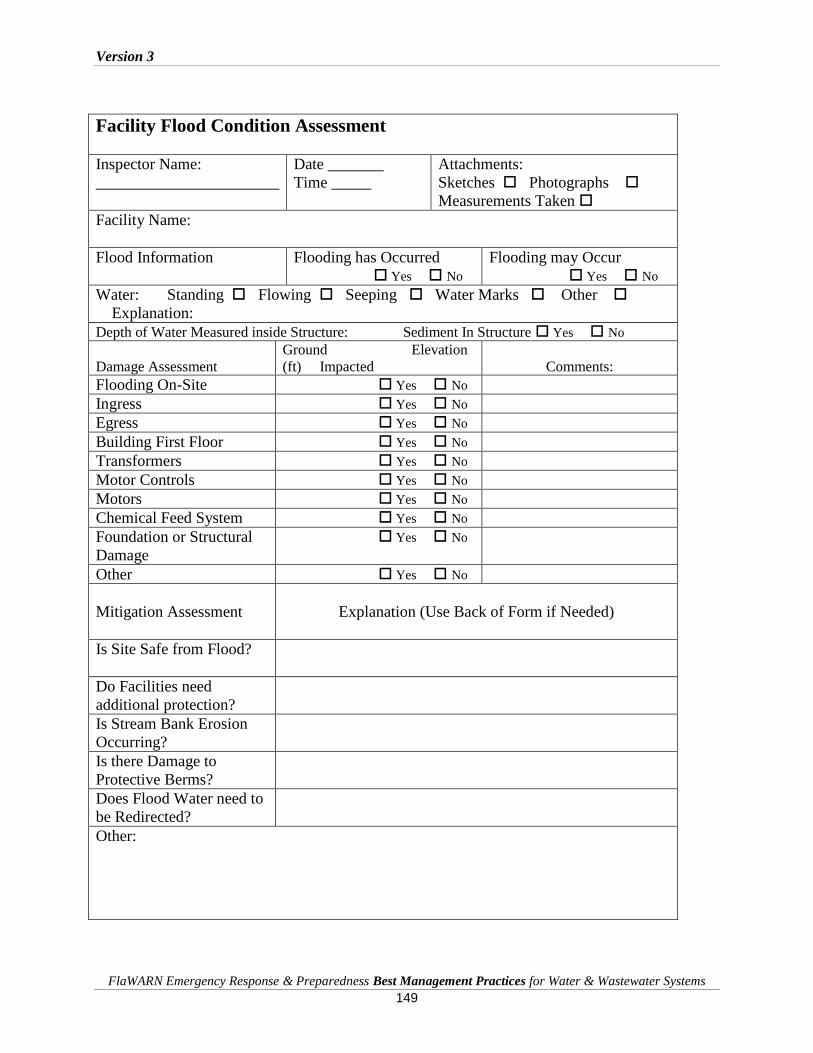
Version 3
FlaWARN Emergency Response & Preparedness Best Management Practices for Water & Wastewater Systems
149
Facility Flood Condition Assessment
Inspector Name:
_______________________
Date _______
Time _____
Attachments:
Sketches Photographs
Measurements Taken
Facility Name:
Flood Information
Flooding has Occurred
Yes No
Flooding may Occur
Yes No
Water: Standing Flowing Seeping Water Marks Other
Explanation:
Depth of Water Measured inside Structure: Sediment In Structure Yes No
Damage Assessment
Ground Elevation
(ft) Impacted
Comments:
Flooding On-Site Yes No
Ingress Yes No
Egress Yes No
Building First Floor Yes No
Transformers Yes No
Motor Controls Yes No
Motors Yes No
Chemical Feed System Yes No
Foundation or Structural
Damage
Yes No
Other Yes No
Mitigation Assessment
Explanation (Use Back of Form if Needed)
Is Site Safe from Flood?
Do Facilities need
additional protection?
Is Stream Bank Erosion
Occurring?
Is there Damage to
Protective Berms?
Does Flood Water need to
be Redirected?
Other:

Version 3
FlaWARN Emergency Response & Preparedness Best Management Practices for Water & Wastewater Systems
150
Post-Flood Response Procedures
The safety of employees must always be the first priority in a post flood response. The
following precautions apply:
Return to the area only after it has been declared safe by local emergency
management officials. Partially or totally submerged transformers that may be
live are dangerous and can cause electrocution.
Identify potential electrical hazards and solicit advice and assistance from the
power company to minimize the dangers. Always report and stay clear of downed
or damaged power lines.
Turn off all utilities associated with utility facilities to prevent further damage and
minimize electrical and explosive hazards.
Never attempt to start a motor or control panels that has been submerged by
water. This will result in irreversible damage to systems that may be salvageable.
It is important to begin salvage operations for flooded electrical equipment as
soon as possible (ASAP) after flood waters recede below them if they are to be
salvaged in-place.
Cleaning Flooded Utility Equipment following Damage by Fresh Water
Moisture in an electrical circuit will carry stray current and result in direct shorts damage to
electrical equipment. High humidity will cause the moisture to collect on electrical components
when the temperature cools, such as in the evening hours. The first priority in a salvage operation
is to remove all sources of moisture from the building itself.
Removing Sources of Continued Moisture
Carefully remove trapped mud and collected water/storm debris as water recedes
from buildings. Do not unnecessarily damage any electrical equipment or motors
in clean up activities.
Remove standing water and water-logged furnishings and debris that maintain a
source of moisture within the structure.
Drain the water from low areas and corner spaces. Standing water will migrate
and perpetuate the moisture problems.
All furnishings and furniture should be moved to allow air movement and
ventilation around them.
Remove and dry water soaked rugs, paper, books, boxes, and other wet materials.
Remove any water soaked insulation; remove insulation from cavity wall
construction if any.
Silt and trapped moisture inside closed electrical components will combine to reduce resistance
and carry higher loads of stray current. Thus the moisture and silt must be removed. Silt is also
hydroscopic, so leaving it in place will result in moisture being attracted with resultant electrical
equipment failure.
Version 3
FlaWARN Emergency Response & Preparedness Best Management Practices for Water & Wastewater Systems
151
Removing Trapped Water and Silt from Electrical Control Equipment,
Connections and Motors
Check and drain trapped water from mechanical chases, equipment control panels,
electrical boxes and HVAC ductwork.
Rinse remaining mud, dirt and flood debris from all surfaces with freshwater. Do
not use high pressure water on electrical equipment. This will force silt areas
which will not be easy to remove.
Open electrical control panels and wash out any silt with fresh water. Do not hose
electrical devices, contacts or connections. These should be carefully cleaned with
rags, deionized water and a tooth brush.
Remove any obviously damaged electrical components that contain water inside
of them such as relays.
Open electrical outlets and mechanical chases and rinse these areas thoroughly.
Check wiring and connections for damage and repair as required. Leave areas
open to dry before closing them.
Open up motors that have been submerged and wash out all silt with copious
amounts of low pressure fresh water.
Drying of Electrical Equipment
It is important that flooded electrical equipment be thoroughly cleaned to remove all sources of
stray current such as silt and trapped moisture. After the electrical equipment is cleaned
precautions must be taken to ensure that it is completely dry. This is accomplished by physical
drying such as use of a hair dryer, displacing moisture with dry air and preferably by the use of a
dehumidifier. The dehumidifier is preferred since it can draw moisture from areas where it may
be trapped. This is accomplished by lowering the humidity within a panel and/or building that
houses electrical equipment and motors that have been flushed and cleaned with water to as low
as 20% humidity.
Spot dry areas where water was used for flushing or cleaning with an electric hair
dryer
Set up a dehumidifier(s) to blow air across electrical cabinets and motors to
ensure that the equipment is completely dried out. Continue the process until the
inside humidity is lowered to below 40%. Dryer conditions improve the
possibility of successful recovery of the electrical equipment and will pull
moisture from hard to reach places.

Version 3
FlaWARN Emergency Response & Preparedness Best Management Practices for Water & Wastewater Systems
152
Checklists for Water and Wastewater
Utilities for Preparing and Responding to
Flood Events
Florida Rural Water Association August 2008

Version 3
FlaWARN Emergency Response & Preparedness Best Management Practices for Water & Wastewater Systems
153
Flood Advisory
A Flood Advisory is a notice of the potential for flooding (increasing water flows/levels) to
occur in the near future. The Flood Advisory is intended to provide notice to municipalities and
emergency services that measures should be taken to prepare for possible flooding.
Municipalities should 'be prepared' to respond to flooding problems.
A Flood Advisory is issued when there is a potential for flooding to occur in low-lying areas.
Nuisance or minor flooding of access roads, backyards, basements, etc. is anticipated.
Buildings/people are not at risk.
Employee/Supervisor/Manager Tasks for Flood Advisory
Item Dept. Action Item
All Review Storm Procedures and Checklists All Implement all Checklists All Review and Update Staffing Responsibilities and Work Shifts All Review Your Duty Assignments All Ensure that Callout Rosters and Information is Current All Review Storm Status and Timeframes for Activities All Check with Supervisor for Special Instructions All Check Personal Work Supplies and Replenish All Ensure that Employees have been provided with Instant Cameras All Contact Vendors/Suppliers for any Critical Supplies All Inventory Pumps and Hoses; Replace and Replenish as Needed All Top off Fuel in Work Vehicles and Generators All Check PPE. Insure Raingear and Boots are available All Replace/Charge batteries in electronic equipment and cell phone and secure
spare batteries for other equipment All Implement Personal Family Preparedness Plan especially for those in low areas All
All
All
All
All
All
All
Additional Notes and Comments

Version 3
FlaWARN Emergency Response & Preparedness Best Management Practices for Water & Wastewater Systems
154
Manager/Supervisor Tasks for Flood Advisory
Item Title Action Item
Manager/Supv. Review Flood Preparedness Plan and Checklists with Employees Manager/Supv. Review and Update Staffing Requirements for Department Manager/Supv. Ensure that Callout Rosters and Information is Current/Call all numbers Manager/Supv. Review Storm Status and Timeframes for Activities Manager/Supv. Check with Supervisor for Special Instructions Manager/Supv. Review Communication Requirements with Upper Management Manager/Supv. Review any Interdepartmental Coordination Procedures Manager/Supv. Review Call Lists for Public Works (Roads, Bridges and Flooded Catch Basins) Manager/Supv. Check Personal Work Supplies and Replenish Them Manager/Supv. Inventory Work Supplies for Employees and Replenish Them Manager/Supv. Ensure that Field Personnel have Forms to Document Activities, especially Flood
Status and Flood Related Information Manager/Supv. Test and Check Operation of all Communications Equipment Manager/Supv. Review Staging Equipment, Supplies and Employees at Remote Sites where
Flooding may Occur Manager/Supv. Review Procedures for Plant Flood Proofing and Special Monitoring and
Pumping Procedures to be Implemented Manager/Supv. Review Plans for Flood Proofing Utility Facility Installations Manager/Supv. Ensure that Sand and Sandbags are available (see BMPs for estimating)
Manager/Supv. Implement Sandbag Protection Plans for Utility Facilities
Manager/Supv. Implement Personal Family Preparedness Plan Especially for Families that are
situated in Low Areas or Could be impacted by Flooding
Additional Notes and Comments:
______________________________________________________________________________
______________________________________________________________________________
______________________________________________________________________________

Version 3
FlaWARN Emergency Response & Preparedness Best Management Practices for Water & Wastewater Systems
155
Flood Watch
A Flood Watch means that flooding conditions have been identified and created or will create a
significant risk for flooding in your area. When flooding does occur a “Flood Warning” is
issued.
Manager/Supervisor Tasks for Flood Watch
Additional Notes and Comments:
______________________________________________________________________________
__________________________________________________________________
________________________________________________________________________
Item Title Action Item
Manager/Supv. 1.) Evaluation of Flood Threats and Actions Considered
Manager/Supv. Have Facilities been evaluated using SLOSH model or other Flood
Prediction tools available to the Utility?
Manager/Supv. Are the dikes or berms that are in-place contiguous and can they
function at higher elevations by relatively minor filling or build up of
surrounding ground?
Manager/Supv. Are the existing dikes, berms or other structures adequate to withstand
erosion that may be caused by changes in velocity and higher water
levels and can they be strengthened by the addition of rip-rap or other
erosion control measures?
Manager/Supv. Where construction of physical barriers and raising of protective
separations are not feasible can a smaller area be protected with a
cofferdam built around the facility?
Manager/Supv. Can provisions be made to use existing block buildings as protection
by sealing off doors, window vents or louvers?
Manager/Supv. Have Pumps been Placed inside Facilities where they may be
needed?
Manager/Supv. Have Floor Drains and other means of water intrusion been
considered and physically plugged off?
Manager/Supv. Are there other areas that should be considered for sandbags
protection?
Manager/Supv. 2.) Implementation of Flood Mitigation & Housekeeping Measures
Manager/Supv. Initiate Critical Facility Inspection and Rotation Schedule with
Employees
Manager/Supv. Cease all construction work and secure open trenches
Manager/Supv. Ensure Response Vehicle are loaded and ready
Manager/Supv. Evaluate and Special Shut Downs such as known areas of Flood
Inundation.
Manager/Supv. Ensure that Department IC and Plant Communication Centers are
Activated
Manager/Supv. Make sure that Housekeeping Issues such as Emergency Payroll,
Emergency Cash, Fuel Cards, etc. have been Initiated
Manager/Supv. Cease all construction work and secure open trenches
Manager/Supv. Ensure that Response Vehicle are loaded and ready

Version 3
FlaWARN Emergency Response & Preparedness Best Management Practices for Water & Wastewater Systems
156
Employee Tasks for Flood Watch
Additional Notes and Comments:
______________________________________________________________________________
______________________________________________________________________________
___________________________________________________________
Item Title Action Item
All Employees 1. ) General Instructions for Employees for “Flood Watch” Conditions
Under a Flood Watch intense rainfall will result in conditions of localized
backup and ponding of water in streambeds and low areas. Employees are
instructed to monitor these conditions and immediately report flood
threats to utility facilities (plants, lift stations, pumping stations, exposed
pipeline and well sites) so that corrective actions may be quickly
implemented. Communications between departments (Collections,
Treatment and Water Distribution) is critical during this phase.
Employees Review Food Preparedness Plan
Employees Review Food Watch Tasks, these generally include monitoring of critical
locations where employees have been assigned to monitor for Possible
Flood Impacts
Employees Review Storm Status and Timeframes for expected Conditions
Employees Check with Supervisor for Special Instructions on Inspection of Critical
Areas such as Stream Banks or Exposed Pipelines where problems may
occur
Employees Check Status of Critical Facilities where Flood Protection has been
Installed; Report and possible mitigation or reinforcement of protection
required
Employees Investigate and locate any sewage spills; these are generally indicative of
hydraulic problems that may mean manhole covers have been blown near
streams
Employees Check that Pumps and Hoses have been pre-positioned at critical facilities
and are operable
All Employees 2. ) Standing Actions for Employees for “Flood Watch” Conditions:
Investigation, Monitoring, Reporting and Documentation
Under a Flood Watch intense rainfall may result in hydraulic overloads to
wastewater collection pipelines, lift stations and treatment plants. These
conditions produce characteristic identifiers which include: sewage
discharge from manholes in streets and low areas, pumping stations in
high level alarm condition, excessive sand production at grit removal
facilities, and citizen reports of unusual odors, sewage backups and
sewage spills. Employees should investigate, monitor, report and
document these conditions and await instructions on corrective actions to
be employed.
Employees Review Duty Assignments with Supervisor
Employees Make Communication Check to Ensure Method of Communication is
working
Employees Ensure that disposable camera and “Flood Reporting Forms” are stocked
Employees Note and report any condition that may make facilities especially
susceptible to flood impacts

Version 3
FlaWARN Emergency Response & Preparedness Best Management Practices for Water & Wastewater Systems
157
Flood Warning
A Flood Warning means that flooding is occurring or is imminent. Under these conditions
utility facilities such as pipelines, lift stations, treatment plants and pumping stations may be
threatened or inundated.
Flood Warnings will provide some time for flood mitigation efforts to be implemented.
Flash Flood Warnings will generally not provide enough response time for mitigation. Where
Flash Flooding occurs, generally restoration after the flooding subsides is the most likely and
appropriate response.
Manager/Supervisor Tasks for Flood Warning
Item Title Action Item
Manager/Supv. Institute 24/7 Coverage Shifts and Release Employees not required
Review Facility Flood Condition Assessment Form (see FlaWARN
BMPs) with employees (Form is included at the back of this document)
Manager/Supv. Review Localized Flooding Information received from EOC and/or
Utility Command Center
Manager/Supv. Dispatch Crews to Critical Facilities located in Flood Prone Areas for
Assessment
Manager/Supv. Dispatch Crews to Areas where spills have been reported for Inspection
Manager/Supv. Review critical trigger points such as Lift Stations in High Water Alarm
and dispatch crews for assessment as appropriate
Manager/Supv. Dispatch Crews to Areas where spills have been reported for Inspection
Manager/Supv. Ensure that Critical Facility Inspection Information Communication
Channels are open and that field information is being evaluated
Manager/Supv. Inspect all Flood Protection Measures that have been installed at
Critical Facilities
Manager/Supv. Move Vehicles and Equipment to Higher Ground as Appropriate
Manager/Supv. Adjust inspection routes as needed to ensure immediate attention to
critical facilities.
Manager/Supv. Report any unusual Flood Conditions to Supervisor
Manager/Supv.
Special Instructions for Managers and Supervisors for Flood Warning Conditions:
Wastewater Collection and Lift Stations:
1. Look for possible flooding of lift stations in low lying areas.
2. Periodic inspections should be made of all lift stations in low lying and flood prone areas.
3. All spills should be addressed since they are indicative of later inflow entry points.
4. Small lift stations that specifically service low lying areas that are completely flooded can
be shutdown to prevent hydraulic overloads to receiving pipelines. Pumping storm water
serves no purpose.
5. Lift stations that are serviced by above ground transformers that are flooded pose the
threat of electrocution to employees and to the public.
Water Supply and Distribution: 1. Positive pressure must be maintained in flooded areas to prevent intrusion of contaminants.
2. Contaminated water may enter wells through vent piping provided with vertical turbine
pumps.
3. Pumping stations should be protected with sandbags or berms and pumps with floor drains
plugged to prevent water from back flowing through storm water removal systems.

Version 3
FlaWARN Emergency Response & Preparedness Best Management Practices for Water & Wastewater Systems
158
Employee Tasks for Flood Warning
Item Title Action Item
Employees Review Storm Status and Timeframes for expected Conditions Employees Check with Supervisor for Special Instructions on Inspection of Critical Areas such
as Stream Banks or Exposed Pipelines where problems may occur Employees Check Status of Critical Facilities where Flood Protection has been Installed;
Report and possible mitigation or reinforcement of protection required Employees Investigate and locate any sewage spills; these are generally indicative of hydraulic
problems that may mean manhole covers have been blown near streams Employees Initiate Corrective Actions such as Repairs or Modifications to Sandbags, Berms or
to conditions that may be addressed to mitigate flood damage to Utility Facilities
Employees Document Flood Conditions at Facilities with photographs and Flood Assessment
Form Employees Document and Report all Pertinent Flood Conditions
Employees Report Flooded Streets and especially moving water.
Employees Report downed power lines, submerged transformers and electrical wires
Employees Maintain Contact with Supervisor/IC and Respond to Special Requests
Employees Perform Communications Checks every 30 minutes
Employees Employees Employees
Additional Notes and Comments:
______________________________________________________________________________
______________________________________________________________________________
____________________________________
Special Instructions to Field Employees:
1. Six inches (6”) of moving water is dangerous. Even if the water appears shallow enough
to cross, don't try it. Water hides dips in the road. Worse yet, there may be no road at all under the water. Flooding can scour away the entire road surface and a significant amount of ground beneath.
2. Never walk or drive through rushing floodwaters. If your vehicle stalls, abandon it
immediately and climb to higher ground. 3. Six inches (6”) of water will reach the bottom of most vehicles, causing loss of
control or possible stalling. 4. One foot (12”) of water will float most vehicles. 5. Two feet (24”) of rushing water can sweep away most vehicles — including SUVs
and pick-ups.
6. Avoid rising waters, storm drains and sewers. Move to higher ground.
7. Watch out for snakes and small animals that might seek shelter in utility facilities.
8. Never enter buildings surrounded by floodwaters.
9. Stay away from downed power lines, submerged transformers and electrical wires

Version 3
FlaWARN Emergency Response & Preparedness Best Management Practices for Water & Wastewater Systems
159
Flood Impact and Restoration Manager/Supervisor Tasks
Item
Title Action Item
Manager/Supv. Ensure that Wind Advisory (below 40 MPH ) has been lifted for employee safety Manager/Supv. Establish Flood Assessment Teams for Restoration of Critical Facilities Manager/Supv. Reestablish Communications Checks every 30 minutes Manager/Supv. Reestablish Communications with Operations sites; obtain updated Status of all
Facilities Manager/Supv. Monitor Storm and Local Weather for Additional Rainfall Manager/Supv. Maintain Contact w/ EOC and EOC Liaison Manager/Supv. Monitor Newscasts Manager/Supv. Develop & Disseminate Internal/External Communications Manager/Supv. Monitor and Apprise EOC of System Status Manager/Supv. Provide Updates on Assessment and Outages for Facilities in Real Time Manager/Supv. Identify Employee/Public Safety Concerns Manager/Supv. Develop Internal/ External Safety Messages Manager/Supv. Provide information on Known Flooding Hazards Manager/Supv. Provide Information on Utility facilities, i.e. wires, spills, water main breaks,
pulled water services, spills and visible leaks and main breaks Manager/Supv. Establish Teams for field inspection of critical pipelines and low lying areas that
have been inundated. Manager/Supv. For Flooded Electrical Equipment, See FRWA - BMPs for Restoration of
Electrical Equipment Manager/Supv. Return Staff to Normal Operations Manager/Supv.
Manager/Supv.
Restoring Facilities after Flooding:
Wastewater Treatment:
1. Maintain Bacterial Communities necessary for Waste Treatment by Discontinuing Wasting.
2. Ensure that Bar Screens remain functional at all times to prevent Blockage that can result in
Flooding of Plant Site.
3. Monitor Grit Removal Facilities for extra Sand Loading that is indicative of Inflow into
Collections Systems.
4. Monitor average flow conditions that should fall to normal a few days after storm passes.
Continuous high flows after storm passes is indicative of high inflow conditions that indicates
open connections with area streams or water bodies.
5. Monitor Lift Station High Water Alarms that do not subside after storm passes. These are
indicative of direct inflow into the collection system.
Wastewater Collection:
1. Mobile Home Parks in low areas are notorious for causing inflow problems. Generally
Sanitary Drain Pipes from mobile homes are not tightly sealed and are often left open when
mobile homes move out resulting in massive inflow when areas are flooded.
2. All wastewater collection lines that are located near streambeds should be walked to ensure
that they are structurally stable. Many times under severe flooding conditions streams
meander resulting in bank erosion and pipeline damage. Up and downstream manholes can
be inspected to determine if inflow is significant.

Version 3
FlaWARN Emergency Response & Preparedness Best Management Practices for Water & Wastewater Systems
160
Facility Flood Condition Assessment
Inspector Name:
_______________________
Date _______
Time _____
Attachments:
Sketches Photographs
Measurements Taken
Facility Name:
Flood Information
Flooding has Occurred
Yes No
Flooding may Occur
Yes No
Water: Standing Flowing Seeping Water Marks Other
Explanation:
Depth of Water Measured inside Structure: Sediment In Structure Yes No
Damage Assessment
Ground
Elevation (ft) Impacted
Comments:
Flooding On-Site Yes No
Ingress Yes No
Egress Yes No
Building First Floor Yes No
Transformers Yes No
Motor Controls Yes No
Motors Yes No
Chemical Feed System Yes No
Foundation or
Structural Damage
Yes No
Other Yes No
Mitigation Assessment
Explanation (Use Back of Form if Needed)
Is Site Safe from Flood?
Do Facilities need
additional protection?
Is Stream Bank Erosion
Occurring?
Is there Damage to
Protective Berms?
Does Flood Water need
to be Redirected?
Other:

Version 3
FlaWARN Emergency Response & Preparedness Best Management Practices for Water & Wastewater Systems
161
A 1: Weather/Hurricane Terms and Acronyms (Retrieved 4/7/06 from: http://www-nmcp.med.navy.mil/newsweath/terms.asp)
ARWO Aerial Reconnaissance Weather
AFOS Automation of Field Operations and Services
ASOS Automated Surface Observing Systems
AWIPS Advanced Weather Interactive Processing System
AOC Army Operations Center, Pentagon
ARC American Red Cross
ARES Amateur Radio Emergency Services
ARRL American Radio Relay League
CARCAH Chief, Aerial Reconnaissance Coordination, All Hurricanes
CONUS Continental United States
DAE Disaster Assistance Employee
DAC Disaster Application Center
DCO Defense Coordinating Officer
DFO Disaster Field Office
DOC Department of Commerce
EAS Emergency Alert System
EBS Emergency Broadcast System
EICC Emergency Information and Coordination Center (FEMA)
EMS Emergency Medical Services
EMWIN Emergency Manager's Weather Information Center
EOC Emergency Operations Center
EOP Emergency Operations Plan
ERT Emergency Response Team (FEMA)
ERT-A Advance Element of the Emergency Response Team (FEMA)
ESF Emergency Support Function
EST Emergency Support Team (FEMA)
FAST Field Assessment Team
FCO Federal Coordinating Officer (FEMA)
FEMA Federal Emergency Management Agency
FRP Federal Response Plan
GMT Greenwich Mean Time

Version 3
FlaWARN Emergency Response & Preparedness Best Management Practices for Water & Wastewater Systems
162
GOES Geostationary Operational Environmental Satellite
HES Hurricane Evacuation Study
HF High Frequency
ICS Incident Command System
IT Information Technology Directorate (FEMA)
KM Kilometers
JIC Joint Information Center
M Statute Mile
MB Millibars
MEOW Maximum Envelope of Water or Maximum Envelope of Winds
MERS Mobile Emergency Response Support (FEMA)
MPH Miles Per Hour
MOC MERS Operations Center (FEMA)
M/S Meters Per Second
MT Mitigation Directorate (FEMA)
NASA National Aeronautics and Space Administration
NAWAS National Warning System
NDMS National Disaster Medical System
NECC National Emergency Coordination Center (FEMA)
NEXRAD Next Generation of Radar
NHC National Hurricane Center
NM Nautical Mile
NPSC National Process Serving Center (FEMA)
NTC National Teleregistration Center (FEMA)
NOAA National Oceanic and Atmospheric Administration
NVOAD National Voluntary Organizations Active in Disaster
NWS National Weather Service
NWSFO National Weather Service Forecasting Office
OSC On-Scene Coordinator
OS Operations Support Directorate (FEMA)
PIO Public Information Officer
PT Preparedness, Training and Exercises Directorate (FEMA)
PUP Principle User Processor
RACES Radio Amateur Civil Emergency Service
RADAR Radio Detection And Ranging
Version 3
FlaWARN Emergency Response & Preparedness Best Management Practices for Water & Wastewater Systems
163
RD Regional Director
REACT Radio Emergency Associated Communication Team
ROC Regional Operations Center
RR Response and Recovery Directorate (FEMA)
SCO State Coordinating Officer
SITREP Situation Report
SLOSH Sea, Lake, and Overland Surges for Hurricanes
SOP Standard Operating Procedure
TD Tropical Depression
TS Tropical Storm
TPC Tropical Prediction Center
TAFB Tropical Analysis and Forecast Branch (TPC)
TSB Technical Support Branch (TPC)
USACE United States Army Corps of Engineers
USAF United States Air Force
USCG United States Coast Guard
USGS United States Geological Survey
USN United States Navy
USAR Urban Search and Rescue
UTC Universal Time Coordinate
WFO Weather Forecast Office
Z Zulu Time

Version 3
FlaWARN Emergency Response & Preparedness Best Management Practices for Water & Wastewater Systems
164
A 2: Glossary & Related Links The US-EPA provides a thorough list of water security and response related links at
http://cfpub.epa.gov/safewater/watersecurity, including a glossary and the following:
A to Z Subject Index Bioterrorism Act
Emergency / Incident Planning
EPA Contacts
EPA Environmental Laboratory Compendium
Grants and Funding
Information Sharing
Legislation / Directives
Office of Ground Water and Drinking Water
Office of Water
Publications
Guidance
Homeland Security Presidential Directives
Outreach Materials
Legislation
Newsletters
Reports and Studies
Webcast Presentations
Public Involvement
Related Links
Trade/Industry Organizations
Clearinghouses and Information Centers
Federal Government
State Homeland Security Web Sites
State Drinking Water Protection Web Sites
EPA Program and Regional Offices
Security Enhancements, Research and Technology
Tools and Technical Assistance
Training Courses, Meetings, and Workshops
Vulnerability Assessments
Water Information Sharing and Analysis Center (WaterISAC)
Water Security Home

Version 3
FlaWARN Emergency Response & Preparedness Best Management Practices for Water & Wastewater Systems
165
A 3: FlaWARN Water Security
Abbreviation and Acronym List
AAR After Action Review
AC Alternating current
ACL Access control list
ACOE Army Corps of Engineers
AMSA Association of Metropolitan Sewerage Agencies
AMWA Association of Metropolitan Water Agencies
AP Action Plan
ASCE American Society of Civil Engineers
ASDWA Association of State Drinking Water Administrators
AWWA American Water Works Association
AwwaRF American Water Works Association Research Foundation
BACT Best Available Control Technology
BOD Biological Oxygen Demand
BWN Boil Water Notice
Ca(OCl)2 Calcium hypochlorite
CaO Calcium oxide
CaOH2 Calcium hydroxide
Ca(OCL)2 Calcium hypochlorite
CBR Chemical, biological, or radiological
CBRNE Chemical, Biological, Radiological/Nuclear, and Explosive
CCC Chlorine contact chamber (also, cross connection control)
CCP Communication Cluster Phenomenon
CCTV Closed-circuit television
CDC Center for Disease Control
CFR Code of Federal Regulations
Version 3
FlaWARN Emergency Response & Preparedness Best Management Practices for Water & Wastewater Systems
166
CHIPS Citizens Helping in Policy Service
CIP Capital improvement plan
CMMS Computerized maintenance management system
CPR Cardio-pulmonary resuscitation
CPTED Crime Prevention Through Environmental Design
CWS Community Water System
DBT Design basis threat
DEP Department of Environmental Protection
DHS Department of Homeland Security
DoD Department of Defense
DoS Department of State
EOC Emergency Operations Center
EPA United States Environmental Protection Agency
ERP Emergency Response Plan
ERT Environmental Response Team
ESF Emergency Support Function
EWS Early warning system
FBI Federal Bureau of Investigation
FDEP Florida Department of Environmental Protection
FEMA Federal Emergency Management Agency
FlaWARN Florida's Water/Wastewater Agency Response Network
FOIA Freedom of Information Act
FRWA Florida Rural Water Association
GASB Government Accounting Standards Board
GETS Government Emergency Telecommunications Service
GIS Geographic information system
GPS Geographic positioning system

Version 3
FlaWARN Emergency Response & Preparedness Best Management Practices for Water & Wastewater Systems
167
GSA General Services Administration
HAZMAT Hazardous Materials
HAZWOPER Hazardous Waste Operation and Emergency Response
HCl Hydrochloric acid
HHS Health and Human Services
HMI Human machine interface
HSAS Homeland Security Advisory System
HVAC Heating, ventilation, and air conditioning
IAP Incident Action Plan
IC Incident Commander
ICS Incident Command System
ID Identification
IDS Intrusion Detection System
IED Improvised explosive device
IID Improvised incendiary device
IP Internet protocol
ISAC Water Information Sharing and Analysis Center
JOC Joint Operations Center (established by the FBI)
LEO Law Enforcement Officer
LEPC Local Emergency Planning Committees
LIMS Laboratory Information Management System
LRN Laboratory Resource Network
MHZ Megahertz
MPEG Moving Picture Experts Group
Na2CO3 Soda ash
NaOCl Sodium hypochlorite
NaOH Sodium hydroxide

Version 3
FlaWARN Emergency Response & Preparedness Best Management Practices for Water & Wastewater Systems
168
NFPA National Fire Protection Association
NIC NIMS Integration Center
NIMCAST NIMS Capability Assessment Support Tool
NIMS National Incident Management System
NIOSH National Institute of Occupational Safety & Health
NRP National Response Plan
NRWA National Rural Water Association
O&M Operations and maintenance
OSHA Occupational Health and Safety Administration
PC Personal computer
pH A measure of the activity of hydrogen ions (H+) in a solution and, therefore, its acidity or alkalinity
PIO Public Information Officer
PIR Passive infrared
PLC Programmable logic controller
ppb Parts per billion
PPE Personal protection equipment
PR Press Release
PRV Pressure reducing valves
PSN Public switched network
RAM Random access memory
RAM-D Risk Assessment Methodology for Dams
RAM-WTM Risk Assessment Methodology for Water Utilities
RFID Radio frequency identification
RPG Rocket propelled grenade
RPTB Response Protocol Tool Box
RTU Remote terminal unit
SCADA Supervisory Control and Data Acquisition

Version 3
FlaWARN Emergency Response & Preparedness Best Management Practices for Water & Wastewater Systems
169
SCBA Self-contained breathing apparatus
SERT State Emergency Response Team
SO Sherriff's Office
SOP Standard Operating Procedure
TLV Total Threshold Value
TOC Total Organic Carbon
TREEO Training, Research and Education for Environmental Occupations
UC Unified Command
UF University of Florida
UL Underwriters Laboratory
UPS Uninterruptible power supply
VA Vulnerability assessment
Vac Volts alternating current
Vdc Volts direct current
VOCs Volatile Organic Compounds
VSATTM Vulnerability Self-Assessment Tool
WMD Weapons of Mass Destruction
WTP Water treatment plant
WWTP Wastewater treatment plant

Version 3
FlaWARN Emergency Response & Preparedness Best Management Practices for Water & Wastewater Systems
170
A 4: Florida Division of Emergency Management
Florida’s Division of Emergency Management is responsible for preparing the state to respond to
emergencies, recover from them, and mitigate their impacts. Bureaus include Compliance
Planning & Support, Policy & Planning, Preparedness & Response, and Recovery & Mitigation.
www.floridadisaster.org is designed to support these objectives. This site provides information
and planning tools to the Florida Emergency Management Community. This service is
continually under development. We try to keep the information timely and accurate and will
make every effort to correct errors brought to our attention.
The State Emergency Response Team (SERT) is set up to manage disasters through Emergency
Operations Centers (EOC’s) set up affected counties in preparation and in the aftermath of a
disaster. The SERT mission is to ensure that Florida is prepared to respond to emergencies,
recover from them, and mitigate against their impacts. The SERT Organizational Structure is
shown below:
SERT Organizational StructureSERT Organizational Structure
Operations SectionOperations SectionOPERATIONSOPERATIONS
SECTIONSECTION
Leo Lachat, ChiefLeo Lachat, Chief
EMERGENCYEMERGENCY
SERVICESSERVICES
BRANCHBRANCH
HUMANHUMAN
SERVICESSERVICES
BRANCHBRANCH
INFRASTRUCTUREINFRASTRUCTURE
BRANCHBRANCH
OPERATIONS OPERATIONS
SUPPORTSUPPORT
BRANCHBRANCH
ESFESF--4/94/9
Fire & USaRFire & USaR
ESFESF--88
Health & MedicalHealth & Medical
ESFESF--1010
EnvironmentalEnvironmental
ProtectionProtection
ESFESF--66
Mass CareMass Care
ESFESF-- 1/31/3
Transportation &Transportation &
Public WorksPublic Works
ESFESF--22
CommunicationsCommunications
ESFESF--1111
Water, Ice & FoodWater, Ice & Food
ESFESF--1515
VolunteersVolunteers
and Donationsand Donations
ESFESF--1717
Animal ProtectionAnimal Protection
ESFESF--1212
EnergyEnergy
ESFESF--1616
Law EnforcementLaw Enforcement
RESPONSERESPONSE
LIAISONLIAISON
UNITUNIT
STATESTATE
WARNINGWARNING
POINTPOINT
Version 3
FlaWARN Emergency Response & Preparedness Best Management Practices for Water & Wastewater Systems
171
Hurricane Preparedness
The goal of the SERT Hurricane Preparedness Web site is to inform the public about the
hurricane hazards and provide knowledge which can be used to take ACTION. This information
can be used to save lives at work, home, while on the road, or on the water.
Up to date information on preparing and responding to hurricanes can be found at:
www.nhc.noaa.gov/HAW2/english/intro.shtml
Florida Division of Emergency Management Online Mapping
Florida's Division of Emergency Management provides an Online Mapping service. The purpose
of these maps is to provide the citizens of Florida with current and accurate information which
can be used to prepare for and recover from disasters. There are two types of mapping sites, a
plug-in required site and a non-plug-in site. The plug-in map will provide you with many
functions, while the non-plug-in is limited yet still provides the necessary information you need
in times of disaster. Maps can be accessed at the interactive sites listed below:
Disaster Preparedness Maps
Interactive Florida Map (*NEW* plug-in required, should auto-load)
- Find Evacuation Routes and Zones, Storm Surge Information, and Open Shelter Locations.
(*Need MS Windows XP, 2000, 98 SE, NT 4.0- MS Internet Explorer 5.x, need administrative
rights to install*)
Other Mapping Sites
Hazard Maps - www.HazardMaps.gov
Terra Fly - Aerial Imagery
TAOS - Storm Hazard Model Outputs
USGS GEODE - Geo-Data Explorer
NOAA Fire Detection
US Forestry Service Fire Detection
Additional information can be obtained from the Florida Division of Emergency Management at
the noted WEB sites.

Version 3
FlaWARN Emergency Response & Preparedness Best Management Practices for Water & Wastewater Systems
172
A 5: FlaWARN Mutual Aid Agreement
MUTUAL AID AGREEMENT FOR WATER/WASTEWATER
ARTICLE I. PURPOSE
The Water/Wastewater Mutual Aid Program was established to provide a method whereby
water/wastewater utilities sustaining physical damage from natural or man made disasters could
obtain emergency assistance, in the form of personnel, equipment, and materials and other
associated services necessary, from other water/wastewater utilities. The purpose of this
Agreement is to formally document such program.
ARTICLE II. DEFINITIONS
A. AGREEMENT – The Water/Wastewater Mutual Aid Agreement. The original agreement and
all signatory pages shall be kept at TREEO Center 3900 SW 63rd Blvd., Gainesville, FL 32608
B. PARTICIPATING UTILITY – Any Water/Wastewater utility which executes this Mutual Aid
Agreement.
C. DAMAGED UTILITY – Any Participating Utility which sustains physical damage to its
water/ wastewater system due to a natural or manmade disaster and seeks assistance pursuant to
this Agreement.
D. ASSISTING UTILITY – Any Participating Utility which agrees to provide assistance to a
Damaged Utility pursuant to this Agreement.
E. AUTHORIZED REPRESENTATIVE – An employee of a Participating Utility authorized by
that utility’s governing board to request or offer assistance under the terms of this Agreement. (A
list of the Authorized Representatives for each Participating Utility shall be attached to this
Agreement as Appendix A)
F. PERIOD OF ASSISTANCE – The period of time beginning with the departure of any
personnel of the Assisting Utility from any point for the purpose of traveling to the Damaged
Utility in order to provide assistance and ending upon the return of all personnel of the Assisting
Utility, after providing the assistance requested, to their residence or place of Work, whichever is
first to occur.
G. SCHEDULE OF EQUIPMENT RATES – The latest rates published by Federal Emergency
Management Agency under the response and recovery directorate applicable to major disasters
and emergencies.
H. WORK OR WORK-RELATED PERIOD – Any period of time in which either the personnel
or equipment of the Assisting Utility are being used by the Damaged Utility to provide
assistance. Specifically included within such period of time are rest breaks when the personnel of
the Assisting Utility will return to active Work within a reasonable time. Also, included is
mutually agreed upon rotation of personnel and equipment.
Version 3
FlaWARN Emergency Response & Preparedness Best Management Practices for Water & Wastewater Systems
173
ARTICLE III. PROCEDURE
In the event that a particular utility becomes a Damaged Utility, the following procedure shall be
followed:
A. The Damaged Utility shall contact the Authorized Representative of one or more of the
participating utilities and provide them with the following information:
1. a general description of the damage sustained;
2. the part of the water/wastewater system for which assistance is needed;
3. the amount and type of personnel, equipment, materials and supplies needed and a
reasonable estimate of the length of time they will be needed;
4. the present weather conditions and the forecast for the next twenty-four hours; and
5. a specific time and place for a representative of the Damaged Utility to meet the
personnel and equipment of the Assisting Utility.
6. The identification of Work conditions and special constraints such as availability of fuel
supplies, lodging/meal support, medical facilities, security, communications, etc.
B. When contacted by a Damaged Utility, the Authorized Representative of a Participating
Utility shall assess his utility’s situation to determine whether it is capable of providing
assistance. No Participating Utility shall be under any obligation to provide assistance to a
Damaged Utility. If the Authorized Representative determines that the Assisting Utility is
capable of and willing to provide assistance, the Assisting Utility shall so notify the Authorized
Representative of the Damaged Utility and providing the following information:
1. a complete description of the personnel, equipment and materials to be furnished to the
Damaged Utility.
2. the estimated length of time the personnel, equipment and materials will be available;
3. the work experience and ability of the personnel and the capability of the equipment to
be furnished;
4. the name of the person or persons to be designated as supervisory personnel; and
5. the estimated time when the assistance provided will arrive at the location designated by
the Authorized Representative of the Damaged Utility.
C. The personnel and equipment of the Assisting Utility shall remain, at all times, under the
direct supervision and control of the designated supervisory personnel of the Assisting Utility. In
instances where only equipment is provided by the Assisting Utility, the ownership of said
equipment shall remain with the Assisting Utility and said equipment shall be returned to the
Assisting Utility immediately upon request. Representatives of the Damaged Utility shall suggest
Work assignments and schedules for the personnel of the Assisting Utility; however, the
designated supervisory personnel of the Assisting Utility shall have the exclusive responsibility
and authority for assigning Work and establishing Work schedules for the personnel of the
Assisting Utility. The designated supervisory personnel shall maintain daily personnel time
records and a log of equipment hours, be responsible for the operation and maintenance of the
equipment furnished by the Assisting Utility, and report Work progress to the Damaged Utility.
D. The Damaged Utility shall have the responsibility of providing food and housing for the
personnel of the Assisting Utility from the time of departure from their regularly scheduled Work

Version 3
FlaWARN Emergency Response & Preparedness Best Management Practices for Water & Wastewater Systems
174
location until the time of return to their regularly scheduled Work location. The food and shelter
provided shall be subject to the approval of the supervisory personnel of the Assisting Utility. If
not agreeable, food and shelter shall be provided and paid for as determined by mutual
agreement.
E. The Damaged Utility shall have the responsibility of providing communications between the
personnel of the Assisting Utility and the Damaged Utility.
ARTICLE IV. REIMBURSABLE EXPENSES
The terms and conditions governing reimbursement for any assistance provided under this
Agreement shall be agreed to prior to the providing of such assistance and shall be in accordance
with the following provisions:
A. PERSONNEL – During the Period of Assistance, the Assisting Utility shall continue to pay
its employees according to its then prevailing rules and regulations. The Damaged Utility shall
reimburse the Assisting Utility for all direct and indirect payroll costs and expenses incurred
during the Period of Assistance, including, but not limited to, employee pensions and benefits.
B. EQUIPMENT – The Assisting Utility shall be reimbursed for the use of its equipment during
the Period of Assistance according to the SCHEDULE OF EQUIPMENT RATES established
and published by FEMA. If an Assisting Utility uses an alternate basis of rates for equipment
listed on the FEMA Schedule of Equipment Rates it shall provide such rates to the Damaged
Utility prior to providing assistance. Rates for equipment not referenced on the FEMA Schedule
of Equipment Rates shall be developed based on actual recovery of costs.
C. MATERIALS AND SUPPLIES – The Assisting Utility shall be reimbursed for all materials
and supplies furnished by it and used or damaged during the Period of Assistance, unless such
damage is caused by negligence of the Assisting Utility’s personnel. The measure of
reimbursement shall be the replacement cost of the materials and supplies used or damaged, plus
ten (10) percent of such cost. In the alternative, the parties may agree that the Damaged Utility
will replace, with a like kind and quality as determined by the Assisting Utility, the materials and
supplies used or damaged.
D. PAYMENT – Unless mutually agreed otherwise, the Assisting Utility should bill the
requesting utility for all expenses not later than ninety (90) days following the Period of
Assistance. The requesting utility shall pay the bill in full not later than forty-five (45) days
following the billing date. Unpaid bills shall become delinquent upon the forty-fifth (45th) day
following the billing date, and once delinquent shall accrue interest at the rate of prime plus two
percent (2percent) per annum as reported by the Wall Street Journal.
E. DISPUTED BILLINGS – Those undisputed portions of a billing should be paid under this
payment plan. Only the disputed portions should be sent to arbitration under Article VI.

Version 3
FlaWARN Emergency Response & Preparedness Best Management Practices for Water & Wastewater Systems
175
ARTICLE V. INSURANCE
Each Participating Utility shall bear the risk of its own actions, as it does with its day-to-day
operations, and determine for itself what kinds of insurance, and in what amounts, it should
carry. Nothing herein shall act or be construed as a waiver of any sovereign immunity or other
exemption or limitation on liability that a Participating Utility may enjoy.
ARTICLE VI. ARBITRATION
All disputes between two or more participating utilities arising from participation in this
Agreement, which cannot be settled through negotiation, shall be submitted to binding arbitration
before a panel of three persons chosen from the members of this Mutual Aid Agreement which
are participating utilities, excluding those members that are parties to the dispute.
Each party to the dispute shall choose one panel member and those panel members shall agree on
one additional panel member. The panel shall adopt rules of procedure and evidence, shall
determine all issues in dispute by majority vote and shall assess damages. The decision of the
panel shall be final and binding upon the parties to the dispute.
NOW, THEREFORE, in consideration of the covenants and obligations contained herein, the
participating utility listed here, as a Participating Utility duly executes this Water/ Wastewater
Mutual Aid Agreement this ________ day of _____________, 20 __ .
Water/Wastewater Utility Representative(s):
By:______________________
Title:_____________________ ____________________________________ Please Print Name
By: ______________________
Title: _____________________ ______________________________________
Please Print Name
Name of Participating Utility: ____________________________ Please Print Name of Utility
(Please note: Attach a copy of your FlaWARN registration form to this document when you submit it. Thank you.)
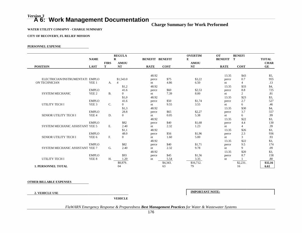
Version 3
FlaWARN Emergency Response & Preparedness Best Management Practices for Water & Wastewater Systems 176
WATER UTILITY COMAPNY - CHARGE SUMMARY
CITY OF RECOVERY, FL RELIEF MISSION
PERSONNEL EXPENSE
NAME
REGULA
R BENEFIT BENEFIT
OVERTIM
E
OT
BENEFIT
BENEFI
T TOTAL
POSITION LAST
FIRS
T
AMOU
NT RATE COST
AMOU
NT RATE COST
CHAR
GE
ELECTRICIAN/INSTRUMENTATION TECHNICIAN
EMPLOYEE 1 A.
$1,543.04
48.92
percent
$754.86
$3,226.50
13.35
percent
$43
0.74
$5,
955.13
SYSTEM MECHANIC EMPLOYEE 2 B.
$1,2
41.60
48.92
percent
$607.39
$2,538.00
13.35
percent
$33
8.82
$4,
725.81
UTILITY TECH I
EMPLO
YEE 3 C.
$1,041.6
0
48.92perce
nt
$50
9.55
$1,74
3.55
13.35perce
nt
$232.7
6
$3,527
.46
SENIOR UTILITY TECH I
EMPLO
YEE 4 D.
$1,328.8
0
48.92perce
nt
$65
0.05
$2,27
5.38
13.35perce
nt
$303.7
6
$4,557
.99
SYSTEM MECHANIC ASSISTANT
EMPLO
YEE 5 E.
$82
2.40
48.92perce
nt
$40
2.32
$1,68
1.23
13.35perce
nt
$224.4
4
$3,130
.39
SENIOR UTILITY TECH I
EMPLO
YEE 6 F.
$1,1
48.0
0
48.92
perce
nt
$56
1.60
$1,96
5.00
13.35
perce
nt
$26
2.3
3
$3,
936
.93
SYSTEM MECHANIC ASSISTANT
EMPLO
YEE 7 G.
$82
2.40
48.92
perce
nt
$40
2.32
$1,71
9.78
13.35
perce
nt
$22
9.5
9
$3,
174
.09
UTILITY TECH I
EMPLO
YEE 8 H.
$93
1.20
48.92
perce
nt
$45
5.54
$1,56
3.35
13.35
perce
nt
$20
8.7
1
$3,
158
.80
1. PERSONNEL TOTAL
$8,879.
04
$4,343.
63
$16,712.
79
$2,231.
16
$32,16
6.61
OTHER BILLABLE EXPENSES
2. VEHICLE USE IMPORTANT NOTE:
VEHICLE
Charge Summary for Work Performed A 6: Work Management Documentation

Version 3
FlaWARN Emergency Response & Preparedness Best Management Practices for Water & Wastewater Systems
177
TYPE MILES
RA
TE
*
AM
OU
NT
It is essential that you provide documentation of specific utility pay
policies that provide basis for calculations such as definition of overtime, overtime pay if different from standard time and a half,
etc. Vehicle# WS218 - 2000 F-350 Ford
Truck
ROUND TRIP MILES (547 EA Way) 1,094
$0
.
45
$
4
92
.
30
MOSS POINT MILES(12
Days) 360
$
0
.4
5
$
16
2
.0
0
Vehicle# WS278 - 2003 GMC Sierra 3500 Truck
ROUND TRIP MILES (547
EA Way) 1,094
$
0
.
4
5
$4
9
2
.
3
0
MOSS POINT MILES(12 Days) 360
$0
.
45
$
1
62
.
00
Vehicle# WS327 - 2004 Chevy
Silverado 3500 Truck
ROUND TRIP MILES (547
EA Way) 1,094
$
0
.4
5
$
49
2
.3
0
MOSS POINT MILES(12 Days) 360
$0
.
45
$1
6
2.

Version 3
FlaWARN Emergency Response & Preparedness Best Management Practices for Water & Wastewater Systems
178
0
0
4,362
$1,9
62.9
0 TOTAL VEHICLE COST
*FEMA AUTHORIZED RATE TOTAL COST
3. MEALS
PERSON
NEL
$32,16
6.61
MEAL
VEHICL
E
$1,962.
90
PLACE
AM
OU
NT
MEA
LS
$1,
140.26
LOD
GIN
G
$1,
238
.72
See Attached Detail
$1,1
40.2
6 TOTAL
MEALS
OTHER
SUPPLIES
$3,
099
.69
4. LODGING
GRAND
TOTAL $39,60
8.18
LODGI
NG
PLACE
AM
OU
NT
Edison Wathall Hotel
$1,2
38.7
2 TOTAL
LODGING
5. OTHER REQUIRED SUPPLIES
OTHE
R
ITEMS
AM
OU
NT
See Attached Detail
$3,0
99.6
9 TOTAL
OTHER

Version 3
FlaWARN Emergency Response & Preparedness Best Management Practices for Water & Wastewater Systems
179
YOUR COMPANY LOGO
YOUR COMPANY
NAME Date: 10/01/20XX
Invoi
ce #: XXXXXX
123 Main Street
Assisting Utility, FL 12345-0000
Ph: (123) 456-7890
Fax: (123) 456-7891
Bill To Copy To
CITY OF RECOVERY FLAWARN HQ
123 Main Street UF/TREEO Center
Recovery, FL 12345-0000 3900 SW 63rd Blvd
Gainesville, FL 32608
Ph: (987) 654-3210
Item Meter # Description Unit Quantity Unit Price Amount
1
Katrina FlaWARN
Responder
To: City of Recovery,
FL
SERT Mission #999
8 Employees for 12 days $32,166.61
Sept 3rd - Sept 14th,
20XX
Vehicle expense $1,962.90
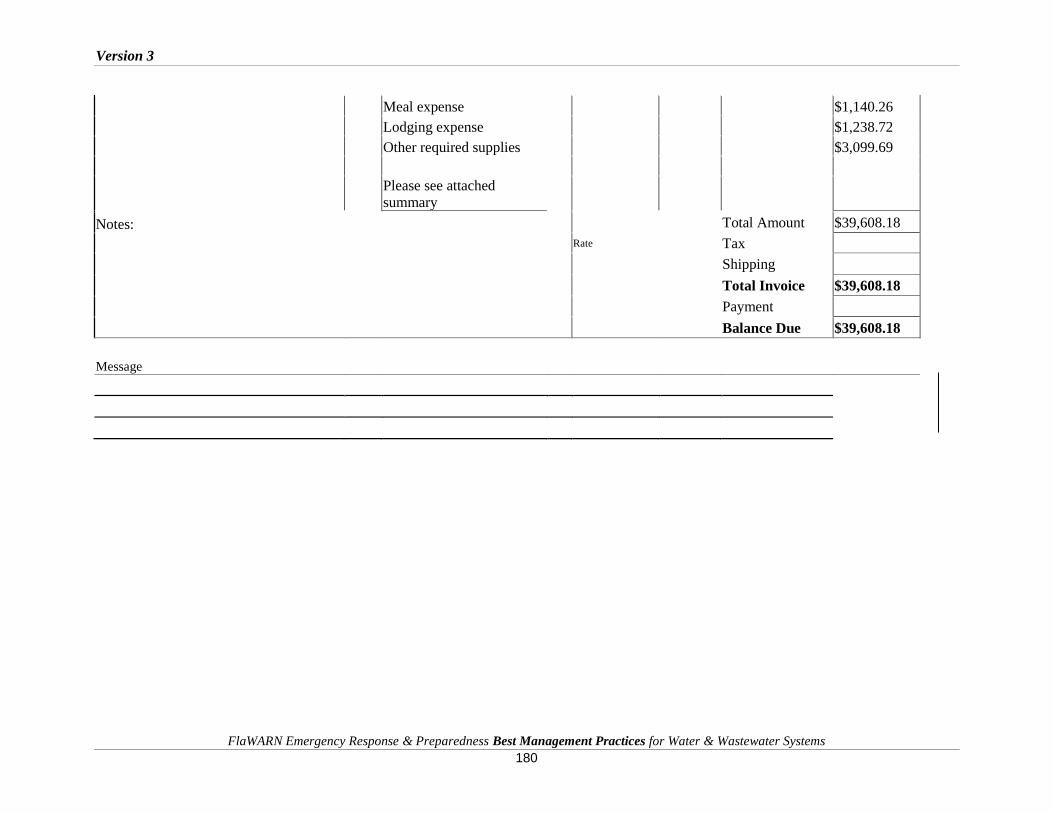
Version 3
FlaWARN Emergency Response & Preparedness Best Management Practices for Water & Wastewater Systems
180
Meal expense $1,140.26
Lodging expense $1,238.72
Other required supplies $3,099.69
Please see attached
summary
Notes: Total Amount $39,608.18
Rate Tax
Shipping
Total Invoice $39,608.18
Payment
Balance Due $39,608.18
Message
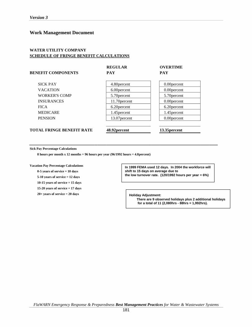
Version 3
FlaWARN Emergency Response & Preparedness Best Management Practices for Water & Wastewater Systems
181
Work Management Document
WATER UTILITY COMPANY
SCHEDULE OF FRINGE BENEFIT CALCULATIONS
REGULAR OVERTIME
BENEFIT COMPONENTS PAY PAY
SICK PAY 4.80percent 0.00percent
VACATION 6.00percent 0.00percent
WORKER'S COMP 5.70percent 5.70percent
INSURANCES 11.70percent 0.00percent
FICA 6.20percent 6.20percent
MEDICARE 1.45percent 1.45percent
PENSION 13.07percent 0.00percent
TOTAL FRINGE BENEFIT RATE 48.92percent 13.35percent
Sick Pay Percentage Calculations
8 hours per month x 12 months = 96 hours per year (96/1992 hours = 4.8percent)
Vacation Pay Percentage Calculations
0-5 years of service = 10 days
5-10 years of service = 12 days
10-15 years of service = 15 days
15-20 years of service = 17 days
20+ years of service = 20 days
In 1999 FEMA used 12 days. In 2004 the workforce will shift to 15 days on average due to
the low turnover rate. (120/1992 hours per year = 6%)
Holiday Adjustment: There are 9 observed holidays plus 2 additional holidays for a total of 11 (2,080hrs - 88hrs = 1,992hrs).

Version 3
FlaWARN Emergency Response & Preparedness Best Management Practices for Water & Wastewater Systems
182
A 7: Forms for Loaning and Receiving Equipment
Loaning Agency Equipment Release Form
Use this form to:
Document the loaning of equipment
Authorize the loaning of equipment
INSTRUCTIONS:
Complete the form below and record the Loaner Agency’s Inventory Number, the Item Description and
the Method of Delivery. Please use the comment section to provide additional information if needed. List
the Receiver Agency’s delivery location and any special conditions for the equipment loaned.
I hereby accept the responsibility for and authorize the loan of the equipment listed below. The property
has been inspected and has been identified with the following description.
_________________________/_______________ Authorized Loaning Agent
ID NUMBER DESCRIPTION CONDITION
COMMENTS: (hours, length and condition of loan etc)
_____________________________________________________________________________________________
_____________________________________________________________________________________________
__________________________________
Details of Loan Agreement:
Facility Loaning Equipment: ________________________________________________________
Authorized Party of Loaned Equipment: _________________________________________________________

Version 3
FlaWARN Emergency Response & Preparedness Best Management Practices for Water & Wastewater Systems
183
Physical and Mailing address of Loaned Equipment:
_________________________________________________________________
__________________________________________________________________
Phone numbers of Loaned Equipment: _________________________________________________________
Receiver of Loaned Equipment: __________________________________________________________
Return / Delivery Method:

Version 3
FlaWARN Emergency Response & Preparedness Best Management Practices for Water & Wastewater Systems
184
Receiving Agency Equipment Acceptance Form
Use this form to:
Document the receiving of equipment
Authorize the acceptance and responsibility of equipment
INSTRUCTIONS:
Complete the form below with the Receiving Facilities Inventory Number, the Item Description and the
Method of Delivery. Please use the comment section to provide additional information if needed. List the
receiver, location and agreed conditions for any property loaned
I hereby accept the responsibility of the equipment listed below. The property has been inspected and has
been identified with the following description.
_________________________/_______________ Authorized Receiving Agent
ID NUMBER DESCRIPTION CONDITION
COMMENTS: (Fueling, hours, maintenance etc)
_____________________________________________________________________________________________
___________________________________
Details of Loan Agreement:
Facility Receiving Equipment: ________________________________________________________
Authorized Party for Facility: _________________________________________________________ ____
Location of Loaned Equipment: _________________________________________________________
___________________________________________________________________
Contact Phone Numbers: ______________________________________________________________

Version 3
FlaWARN Emergency Response & Preparedness Best Management Practices for Water & Wastewater Systems
185
Physical and Mailing address of Loaned Equipment:
_____________________________________________________________________________________________
______________________________________
Return / Delivery Method:
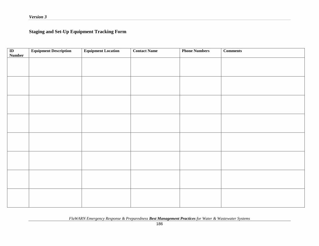
Version 3
FlaWARN Emergency Response & Preparedness Best Management Practices for Water & Wastewater Systems 186
Staging and Set-Up Equipment Tracking Form
ID
Number
Equipment Description Equipment Location Contact Name Phone Numbers Comments
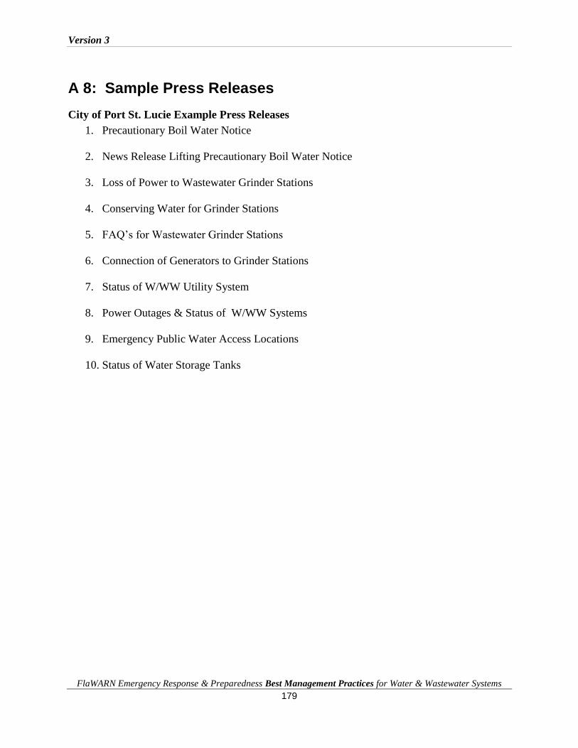
Version 3
FlaWARN Emergency Response & Preparedness Best Management Practices for Water & Wastewater Systems 179
A 8: Sample Press Releases
City of Port St. Lucie Example Press Releases
1. Precautionary Boil Water Notice
2. News Release Lifting Precautionary Boil Water Notice
3. Loss of Power to Wastewater Grinder Stations
4. Conserving Water for Grinder Stations
5. FAQ’s for Wastewater Grinder Stations
6. Connection of Generators to Grinder Stations
7. Status of W/WW Utility System
8. Power Outages & Status of W/WW Systems
9. Emergency Public Water Access Locations
10. Status of Water Storage Tanks
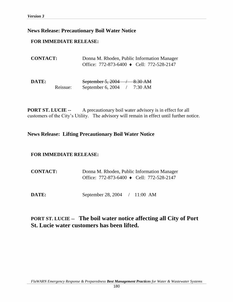
Version 3
FlaWARN Emergency Response & Preparedness Best Management Practices for Water & Wastewater Systems
180
News Release: Precautionary Boil Water Notice
FOR IMMEDIATE RELEASE:
CONTACT: Donna M. Rhoden, Public Information Manager
Office: 772-873-6400 Cell: 772-528-2147
DATE: September 5, 2004 / 8:30 AM
Reissue: September 6, 2004 / 7:30 AM
PORT ST. LUCIE -- A precautionary boil water advisory is in effect for all
customers of the City’s Utility. The advisory will remain in effect until further notice.
News Release: Lifting Precautionary Boil Water Notice
FOR IMMEDIATE RELEASE:
CONTACT: Donna M. Rhoden, Public Information Manager
Office: 772-873-6400 Cell: 772-528-2147
DATE: September 28, 2004 / 11:00 AM
PORT ST. LUCIE -- The boil water notice affecting all City of Port
St. Lucie water customers has been lifted.

Version 3
FlaWARN Emergency Response & Preparedness Best Management Practices for Water & Wastewater Systems
181
News Release: Loss of Power to Wastewater Grinder Stations
FOR IMMEDIATE RELEASE:
CONTACT: Donna M. Rhoden, Public Information Manager
Office: 772-873-6400 Cell: 772-528-2147
DATE: September 5, 2004 / 8:49 AM
PORT ST. LUCIE -- Power failures throughout the City will effect the operation of
wastewater grinder and suburbanaire tank systems.
Therefore, all customers of the City’s Utility that are served by low-pressure sewer
systems (grinder tanks and suburbanaire tanks) are still advised to conserve water use.
Customers should restrict all use of dishwashers and washing machines until further
notice. Do not take long showers. Be conservative about toilet flushing.
News Release: Conserving Water for Grinder Stations
FOR IMMEDIATE RELEASE:
CONTACT: Donna M. Rhoden, Public Information Manager
Office: 772-873-6400 Cell: 772-528-2147
DATE: September 2, 2004
PORT ST. LUCIE -- All customers of the City’s Utility that are served by low-
pressure sewer systems (grinder tanks and suburbanaire tanks) are advised to conserve
water use. Customers should restrict the use of dishwashers, washing machines and long
showers.

Version 3
FlaWARN Emergency Response & Preparedness Best Management Practices for Water & Wastewater Systems
182
News Release: FAQ’s for Wastewater Grinder Stations
CONTACT: Donna M. Rhoden, Utility Public Information Manager
Office: 772-873-6400 Fax: 772-873-6405
DATE: September 24, 2004 / 10:30 AM
PORT ST. LUCIE -- The following information is offered to our customers as before, during,
and after storm or hurricane instructions.
1. Many of the City’s wastewater (sewer) customers are served by low-pressure Grinder
Pump or STEP (septic tank effluent pump) systems. What is a wastewater Grinder
Pump or STEP system?
The system consists of a small electrical pump inside a fiberglass tank that is
typically buried in the front yard of the customer’s property.
2. What happens when the Grinder Pump or STEP tank is full of wastewater?
The electrical pump will automatically run and the wastewater will be pumped
through low-pressure sewer mains to one of the City’s three wastewater trea tment
plants.
3. How much wastewater can an empty residential grinder tank
store?
Approximately 70 gallons. Keep in mind that a toilet uses between 1.5 – 2.5
gallons of water each t ime i t is f lushed.
4. What happens if there is a power failure such that a residence has no
electricity?
If the electrical power is off , the Grinder or STEP system cannot operate.
Therefore, al l Grinder and STEP system customers must conserve water usage unti l
their electric power is restored. They should flush toilets only when absolutely
necessary and not take long showers.
5. What will the Util ity do if a customer does not have electrical power to their
Grinder or STEP system?
The Utility will make every effort possible to pump out or pump down a customer’s Grinder
or STEP system when the storm or hurricane subsides.

Version 3
FlaWARN Emergency Response & Preparedness Best Management Practices for Water & Wastewater Systems
183
6. Can customers connect their private generators to operate their Grinder STEP systems?
Yes, but not until a City Utility employee instructs them on how to do it. Also, the generator must be
220 Volt and it must be a minimum of 5,000 Watts. Customers must provide their own "pigtail"
(cord with plug).
7. Is it safe to drink the City’s water after a hurricane?
A precautionary boil water advisory will be in effect immediately following the hurricane until such
time as the City can assure the integrity of it’s water distribution system and the quality of water in its
system. If you are not able to boil the water, the St. Lucie County Health Dept. recommends that you
add 8 drops of unscented household bleach per gallon of water, and then allow the water to sit for 30
minutes before consuming it.
8. Should the other City water and sewer customers do anything special after a
hurricane?
Yes. All customers of the City’s Util i ty are advised to conserve water use after
the hurricane. They should be especially conservative with toilet f lus hing, and
they should not use dishwashers or washing machines. Customers should not let
water run for a long t ime in a sink or tub, and they should not take long showers.
9. Utility customers should call 873-6400 if they have questions.

Version 3
FlaWARN Emergency Response & Preparedness Best Management Practices for Water & Wastewater Systems
184
News Release: Connection of Generators to Grinder Stations
FOR IMMEDIATE RELEASE:
CONTACT: Donna M. Rhoden, Public Information Manager
Office: 772-873-6400 Cell: 772-528-2147
DATE: September 7, 2004 / 10:45 AM
PORT ST. LUCIE -- Customers of the City’s Utility who have low pressure sewer
grinder systems or STEP systems are requested to contact the Utility before they make
any attempt to connect their personal electric generators to the City’s grinder or STEP
pumps. The Utility will dispatch one of its electricians to the site to instruct customers
on how to make the connections.
Call: 873-6400
News Release: Status of W/WW Utility System
FOR IMMEDIATE RELEASE:
CONTACT: Donna M. Rhoden, Public Information Manager
Office: 772-873-6400 Cell: 772-528-2147
DATE: September 5, 2004 / 8:55 AM
PORT ST. LUCIE -- Due to the continued presence of Hurricane Frances, the
City’s Utility has been unable to deploy damage assessment and repair crews.
However, crews remain ready to activate and respond to system emergencies as soon as
storm conditions subside.

Version 3
FlaWARN Emergency Response & Preparedness Best Management Practices for Water & Wastewater Systems
185
News Release: Power Outages & Status of W/WW Systems
CONTACT: City of Port St. Lucie Utilities
Donna M. Rhoden, Public Information Manager
Office: 772-873-6400 Cell: 772-528-2147
DATE: September 5, 2004 / 8:45 PM
PORT ST. LUCIE -- The City’s entire sewer system is down due to power failures
throughout its utility service area. The City is currently using all available generators to
provide emergency power. The delivery of additional generators is expected tomorrow
to bring some relief until FPL can restore all power.
All customers of the City’s Utility are still advised to limit all water use. Do not use
dishwashers, washing machines, or take long showers, and flush toilets only as
necessary.
News Release: Emergency Public Water Access Locations
FOR IMMEDIATE RELEASE:
CONTACT: Donna M. Rhoden, Public Information Manager
Office: 772-873-6400 Cell: 772-528-2147
DATE: September 5, 2004 / 8:15 PM
PORT ST. LUCIE -- The City’s Utility Systems Department is in the process
of establishing emergency water supply depots at the following locations:
1. Church of God @t Savona / California
2. Mobile gas station @ Gatlin / PSL Blvd.
3. Shell gas station @ Tulip / Darwin
4. Parkway Elementary @ Selvitz / Manville
5. Publix @ Midport / PSL
6. Publix @ Prima Vista Crossings at U.S. #1 / Prima Vista
7. Zapatas on U.S. #1 near Kitterman Rd.
Every attempt will be made to have all of the stations in service by 7:00 AM,
Monday, Sept. 6th.

Version 3
FlaWARN Emergency Response & Preparedness Best Management Practices for Water & Wastewater Systems
186
Residents must bring their own containers. The boil water advisory will be in
effect for each site. Every attempt is being made to deploy adequate Utility
staff so that each depot will be manned around the clock.
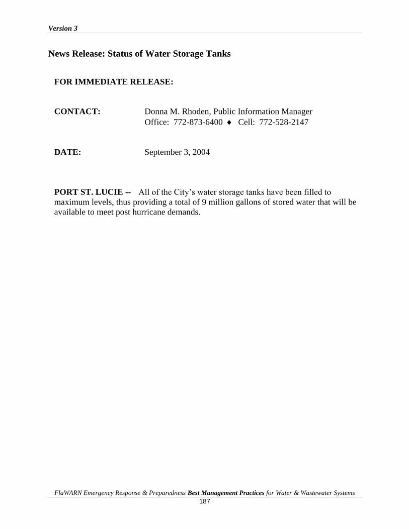
Version 3
FlaWARN Emergency Response & Preparedness Best Management Practices for Water & Wastewater Systems
187
News Release: Status of Water Storage Tanks
FOR IMMEDIATE RELEASE:
CONTACT: Donna M. Rhoden, Public Information Manager
Office: 772-873-6400 Cell: 772-528-2147
DATE: September 3, 2004
PORT ST. LUCIE -- All of the City’s water storage tanks have been filled to
maximum levels, thus providing a total of 9 million gallons of stored water that will be
available to meet post hurricane demands.

Version 3
FlaWARN Emergency Response & Preparedness Best Management Practices for Water & Wastewater Systems
188
Lee County Utilities Hurricane Guide Tips
Before the Hurricane
Locate your residence’s emergency water shut-off valve and remove any shrubbery or
obstructions. Test the water shut-off valve to be sure that it is operational. If the shut-off
valve is not operational, have it repaired or replaced.
Turn off the emergency water shut-off valve if you are leaving your residence prior to a
storm. This will help minimize damage to your home’s interior should a pipe burst inside
the home.
If you turn off the emergency shut-off valve, follow the manufacturer’s recommendations
on turning off your hot water heater and unplug. Some hot water heaters may be
damaged if water supply is turned off for an extended period of time.
Locate your sewer clean-out lid and remove any shrubbery or obstructions in case the
clean-out needs to be located.
After the Hurricane
Due to power outages, water treatment plants will be operating under limiting conditions.
Water pressures will be reduced!
Due to power outages, lift stations that are used to convey sewage to the wastewater
treatment plants will not work or have only limited operations. Over use of toilet
flushing or water going down drains may cause lift stations to overflow and backup into
your home.
Because of reduced pressures and limited operations of lift stations, WATER
CONSERVATION IS A MUST! Remember, just because power has been restored to your
home, does not mean that power has been restored to all lift stations or water and wastewater
treatment plants within your neighborhood.
Limit the amount of toilet flushing.
Abstain from running dishwashers and clothes washers.
Limit the amount water used during a shower or the amount to fill the bathtub.
Turn off all sprinklers! Remember to reset your irrigation timer once power has been
restored.
Abstain from pressure washing, car washing, or any other outdoor use of water that is not
necessary.
Making Your Drinking Water Safe
During a storm event, trees can uproot water pipes allowing the underground pipes to be exposed
to contaminated ground water or create a drop in pressure. Once the storm passes, treat your
water supply as if it is unsafe to drink until you are notified otherwise. Boil water notices will be
issued through your local Health Department and will be announced through your local
Emergency Operations Center (EOC).

Version 3
FlaWARN Emergency Response & Preparedness Best Management Practices for Water & Wastewater Systems
189
The use of bottled water should be used until bacteriological test prove that the water is safe to
drink. If you do not have bottle water here are ways to disinfect your water to make it safe.
Remember to disinfect any water being used for your pets.
Drinking Water
Boil the water for at least ten minutes.
If you do not have power and cannot boil your water, add eight (8) drops of unscented
chlorine bleach per gallon of water. Let the water sit uncapped for at least 10 minutes
before drinking.
Dish Washing
Add fifteen (15) drops of unscented chlorine bleach per gallon to use for rinsing dishes.
Keep them clean until next use.
Showering or Bathing
Showering or bathing in tap water that is under a boil water notice is safe, if you cut
yourself shaving use an antibiotic cream.

Version 3
FlaWARN Emergency Response & Preparedness Best Management Practices for Water & Wastewater Systems
190
A 9: Sample Employee Assistance Plans
City of Tamarac Summary of Employee Assistance after Hurricane Wilma
On Wednesday, October 26, 2005, the City resumed operations notifying
employees to return to work.
Employees were provided special bulletins as often as appropriate to provide information regarding City operations.
Meals including breakfast, lunch and dinner were made available for all employees working on hurricane recovery operations for two weeks.
Employees were provided ice and water on a daily basis to take home.
Employees were allowed to fill their gas tanks at the City’s fueling facilities so they could get to work without waiting in gas lines.
Employees were paid on their regular payday schedules, and were offered the service of cashing personal checks through the City’s customer service office.
Employees were provided contact information so they could communicate with FEMA, which had already declared Broward County eligible for individual assistance.
Employees who had 457 Deferred Compensation accounts, and were affected by the hurricane were given the option of an emergency withdrawal of up to $5,000. This option was made available for 30 days, with a recommendation that all hurricane-related expense records be kept for IRS purposes. For those wishing to withdraw greater amounts, a representative was made available for assistance. Contact information was given and the option of a wire transfer of the funds was provided for those wishing to have the money routed to their accounts.
The City County Credit Union offered emergency interest free 6 month loans to existing members of up to $1,000, as well.
Operation Blue Roof was being implemented in Broward County, so City employees were given application pickup information and program updates with phone numbers, hours of operations, and projected contractor installations.
Employees were provided information regarding the status of Broward County School closures.

Version 3
FlaWARN Emergency Response & Preparedness Best Management Practices for Water & Wastewater Systems
191
Employees were provided information regarding the status of traffic lights.
Employees were provided information regarding Broward County Mass Transit free services.
Employees were asked to assist other employees and to offer support to those impacted by the hurricane by contributing to cleanups, opening their homes for hot showers, telephone or cell phone calls, or for laundry.
Due to anticipated bad weather, employees who experienced significant roof damage in their homes were provided roof tarps to protect their property.
Employees whose homes were badly damaged and had to evacuate were offered temporary housing assistance.
Employees were advised of price gouging and asked to keep their receipts and contact the police if they suspected price gouging. A help number was also offered for employees to contact in the event they experienced gouging.
Emergency withdrawals from 457 Deferred Compensation accounts were made available from all carriers, and requests were typically being processed within 24-48 hours of the receipt of paperwork.

Version 3
FlaWARN Emergency Response & Preparedness Best Management Practices for Water & Wastewater Systems
192
A10: Boil Water Notice Guidelines

Version 3
FlaWARN Emergency Response & Preparedness Best Management Practices for Water & Wastewater Systems
193

Version 3
FlaWARN Emergency Response & Preparedness Best Management Practices for Water & Wastewater Systems
194

Version 3
FlaWARN Emergency Response & Preparedness Best Management Practices for Water & Wastewater Systems
195

Version 3
FlaWARN Emergency Response & Preparedness Best Management Practices for Water & Wastewater Systems
196

Version 3
FlaWARN Emergency Response & Preparedness Best Management Practices for Water & Wastewater Systems
197

Version 3
FlaWARN Emergency Response & Preparedness Best Management Practices for Water & Wastewater Systems
198

Version 3
FlaWARN Emergency Response & Preparedness Best Management Practices for Water & Wastewater Systems
199

Version 3
FlaWARN Emergency Response & Preparedness Best Management Practices for Water & Wastewater Systems
200
A 11: Best Management Practices for Water Main
Breaks and Repairs
Version 3
FlaWARN Emergency Response & Preparedness Best Management Practices for Water & Wastewater Systems
201
Version 3
FlaWARN Emergency Response & Preparedness Best Management Practices for Water & Wastewater Systems
202
A 12: Disinfecting Flooded Wells
Applicability
If drinking water is obtained from a pubic well and you suspect that the well may have been
contaminated, contact your local or state health department for specific advice
Contamination Threats to Wells from Flooding
Flooding provides three pathways for contamination of a well, transport of contaminated water to
the well head that can be present both above and below ground, surface inflow that passes
directly into the well through openings at the ground surface and subsurface infiltration that
enters the well by hydraulic actions caused by the well drawdown. The first flush of water from
storm water facilities is often contaminated to an extent found in raw sewage. Flooding will
transport these wastes directly to the well head.
Even if a well head has not been completely covered over with flood water, a poorly constructed
well can become contaminated from surface water that enters through openings in the well or
seeps in below ground. If you have had any standing water around a well head from a flood, then
there is a good chance the well could be or could become contaminated.
Contamination can occur in both deep well and shallow wells and is not dependant on the
volume of water or flow rate provided by the well. Contamination may be more dilute in a
deeper, high-capacity well, but microorganisms could still affect human health.
The most common side affects of drinking contaminated well water is diarrhea. Diarrhea can be
caused by a host of bacterial and viral pathogens and may occur after a few hours after drinking
or being exposed to contaminated water to several days following exposure. It is not necessary to
drink water to become ill when water is contaminated. Pathways for illness include from
contaminated water on the hands to body openings in the eyes and mouth and from breathing
aerosols that can enter the lungs. For this reason bathing or any other type of contact with
contaminated water should be discouraged.
Fuel and other chemical releases and spills are common during flood events. If floodwaters water
smells like fuel, has a chemical odor, or a sheen, contact your local or state health department to
request a chemical analysis. Floodwater that carries fuels, solvents, pesticides or other chemicals
can contaminate a well with constituents that will not be removed in the water treatment process.
Until you know the chemical constituents that can be contaminating the water and their
concentrations, the well may not be capable of producing water that is safe to use in the short-
term.

Version 3
FlaWARN Emergency Response & Preparedness Best Management Practices for Water & Wastewater Systems
203
Safety Considerations for Cleaning and Disinfecting Wells
You will need to clear hazards away from well heads before attempting to clean and disinfect
wells after floods and other natural disasters. The following precautions will help you do that
safely:
Table 1
Safety Precautions for
Preparing a Well Head for Cleaning and Disinfection
1. Before beginning any action, carefully inspect the area around the well for electrical
and physical hazards. Those may include broken power lines on the ground or in the
water; sharp metal, glass, or wood debris; open holes; and slippery conditions.
2. Wear thick rubber-soled shoes or boots to protect against electrical shock.
3. Turn off all power to the well area before clearing debris. Inspect all electrical
connections for breaks in insulation and for moisture. Turn power back on only if all
connections appear unbroken and dry with no opportunity for shock.
4. Do not turn on any electrical equipment if there is a persistent smell of fuel such as
gasoline coming from the well head. Allow the well to vent. If the smell persists,
contact your local or state health department. Do not continue with disinfection of the
well until the contamination in the well has been removed
5. Before beginning work on the well, clear debris away from it to avoid inadvertently
moving debris into the well.
Once the wellhead area has been safely prepared you can proceed to clean and disinfect the well.
These additional precautions are recommended as you prepare to disinfect the well(s):
Table 2
Additional Safety Precautions for
Preparing a Well for Cleaning and Disinfection
The Chlorine solutions used to clean and disinfect a well can cause chemical burns.
Use rubber gloves, protective eye wear, and waterproof aprons or rain gear when
working with chlorine solutions.
When mixing and handling chlorine solutions, work in well ventilated areas and
avoid breathing vapors. When working in closed spaces, use electrical fans to provide
fresh air. Exposures to chlorine fumes at high concentrations can damage lung tissue
immediately and at low concentrations, exposure as low as 15 minutes duration can
cause illness or injury.
Warn users not to drink or bathe in water until all the well disinfection steps have
been completed and the well has been thoroughly flushed.
Version 3
FlaWARN Emergency Response & Preparedness Best Management Practices for Water & Wastewater Systems
204
Cleaning and Disinfecting Wells Following a Flooded Condition
After following the above safety and health precautions the well is ready for cleaning and
disinfection. The following procedures are recommended for cleaning and disinfecting wells that
may have become contaminated by harmful microorganisms in floods or other natural disasters.
The disinfection process for a well can take from a few hours to a few days to complete. This
process is recommended after floods and when a well has tested positive for coliform bacteria.
Chlorination is a process of flushing your well water system with a chlorine solution to inactivate
pathogens. Chlorination is an effective method to inactivate microbial contamination, but if
sampling shows that continual problems exist and they are linked to the well or groundwater
from flooding, chlorination is only a temporary solution and will not protect the consumer of the
water from microbial illness.
If the well contamination persists, further investigation is needed to determine the source of the
problem. The procedures for well investigation are found in FAC 62-555.315 and 62-555.320.
If electrical power is not available at the well head, a portable generator may be needed to
operate pumps and other equipment. Be familiar with generator operation found in other sections
of this document before turning on a generator, energizing pumps, or any electrical equipment
and have a qualified electrical technician make any electrical connections to prevent serious
injury and damage to equipment..
After ensuring that safety procedures have been addressed, the well is ready for cleaning and
disinfection. The recommended procedures follow:
Table 3
Procedures for Cleaning and Disinfecting Wells
1. Scrub and/or hose off foreign material from the well head, including the well slab,
sanitary seal and pumping equipment. If the well seal was not properly installed
and flooding has occurred, contaminated water, sand and silt may have been
deposited in the well from this source, will be a contamination source and thus
will need to be removed.
2. Swab all top areas with chlorine solution. Since oil from street runoff may be
contained in flood waters and is retained at the surface, it is recommended that a
chlorine dose of 1,000 PPM be used for swabbing. This is about 2 ounces of
bleach per gallon of water.
Contaminated flood water may also have entered the well through the well vent
opening and/or electrical conduits and these should be opened, cleaned and
swabbed with chlorinated water and then flushed with clean water prior to

Version 3
FlaWARN Emergency Response & Preparedness Best Management Practices for Water & Wastewater Systems
205
attempting to disinfect the well. The amount of chlorine needed will be based on
the type and extent of contamination.
3. If flooding inundated the well head it may be impossible to remove all the debris
deposited in the well. Special tools or pumps may be required to remove silt and
sand that has settled to the bottom of the well. Heavy deposits of silt and sand
may damage the well pump if not removed before the pump is started. If flooding
resulted in a condition where considerable amounts of sand and silt were forced
into the well, the pump column and well pump will have to be removed, any
foreign substances removed and the well cleaned thoroughly before attempting
disinfection.
4. In instances of inundation, the well must be opened and all floating debris
removed. The well should be purged by pumping until clear, to remove any
suspended materials. The inside casing will require decontamination by swabbing
from the surface the casing pipe to water level or if extremely deep, by repeated
flushing from the top with strong non-foaming detergent such as Calgon or
Trisocium Phosphate. If the well has been flooded, contaminated materials may
have deposited on the sides of the casing and can be best removed by cleaning.
5. The amount of chlorine to reach shock loading to be used to decontaminate a well
will be determined from Table 5. These values are based on achieving a
concentration of 50 PPM. For disinfecting a well that may have been
contaminated, at least 200 PPM concentration of free chlorine residual must be
maintained. If oil or high levels of organic matter have been washed into the well
concentrations as high as 1000 PPM may be needed. This will also require the
column and well pump to be removed and cleaned.
6. If the pumping units are to be left in the well then these procedures should be
followed. After purging well to clear condition, clean the casing with Calgon or
Trisodium Phosphate by adding about 4 oz. to each gallon of water to be removed
and cycling the well up and down several times. The gallons of mixture to be used
is determined by the drawdown in the well.
7. Chlorine solutions to be added to the well are determined from Table 6. How the
chlorine solution is to be added is determined by whether the pumps are water or
oil lubricated. If oil lubrication is used then chlorine must be added below the
water well surface or it will be carried deep into the well. The solution should be
added by lowering a hose into the well through the well vent if the pumps are oil
lubricated.
This wash water is used to both flush deposits and oxidize any residue along the sides of the
casing. The condition of the well can be visually observed by noting the condition of the lush
water as it is removed. Empty spent rinse water from the well and repeat the process allowing
the well to fill again.

Version 3
FlaWARN Emergency Response & Preparedness Best Management Practices for Water & Wastewater Systems
206
8. Add a chlorine solution to the well until it produces a free chlorine concentration
as shown in Table 6. To determine free chlorine residual a DPD kit must be used.
Cycle the well pump several times to get good chlorine distribution.
Table 5 provides recommended doses to reach acceptable free chlorination levels
in the casing pipe. It is advisable to take a sample to determine that these levels
are met or exceeded. Either unscented bleach liquid or solid chlorine can be used
to disinfect a well.
To disinfect a contaminated well, shock chlorination is necessary. Shock
chlorination cleans the well by oxidation and inactivates pathogens. The more
contamination that is found or suspected the higher the dose of chlorine that needs
to be used.
The highly chlorinated water must be held in the well for 24 hours before it is
flushed out and the system is ready for testing. To determine the approximate
amount of chlorine needed, find the corresponding well diameter in the left
column of the table. Then match the amount of chlorine needed corresponding to
the size of the well found on the right.
It is very important to determine the depth of your well. This information is typically
recorded in an O&M manual. If a the information is not available you will need to estimate
the depth based on your best educated guess, then increase the suggested amounts of chlorine
by 50%.
9. The chlorine solution can be added trough the well vent or the air release valve
may be removed if more diameter is needed. Once the solution is completely
dispensed into the well it must be thoroughly mixed. This is accomplished by
cycling the well pump on and off until a strong chlorine odor is persistent in the
spent water. Drain to waste and do not pump contaminated water into any existing
piping or pressure tanks. Disconnect piping between the pressure tank and pump
if needed to allow contaminated water to flow away from the well and tank.
10. Once the solution is thoroughly mixed the well is ready for disinfecting. Add
additional makeup solution and then repeat this procedure several times at one
hour intervals making sure that the required chlorine residual is maintained. Water
pumped from the well should be clear and have a heavy chlorine odor.
11. After several cycles stop the pump, note the time, and allow the chlorine solution
to remain in the well. The chlorine solution should be left in the well for 24 hours.
Do not leave chlorine in the well for much longer than 24 hours because at high
concentrations it can be corrosive to some pump parts.
12. After the disinfectant has set in the well for the recommended period, turn on the
pump and direct the water to a designated area away from the well. The water in
the well contains high concentrations of chlorine that can be harmful to plants and

Version 3
FlaWARN Emergency Response & Preparedness Best Management Practices for Water & Wastewater Systems
207
aquatic life. Empty the water in an area where plants or streams will not be
harmed. You should continue to pump the well until no chlorine odor is present.
13. Confirm that there is no chlorine residual and take a bacteriological sample in
accordance with DEP Standard Operating Procedures. Properly label, preserve
and transport the sample to an approved laboratory for testing.
Table 4
Determining the amount of water inside
A Well Casing for Adding Detergent
Well Diameter
(inches)
Volume
(gallons per
foot )
4 0.65
6 1.47
8 2.61
12 5.88
16 10.44
20 16.30
24 23.50

Version 3
FlaWARN Emergency Response & Preparedness Best Management Practices for Water & Wastewater Systems
208
Table 5
Determining Chlorine Amounts
for Shock Chlorination (50 PPM) of a Well
Laundry bleach (about 5.25% Hypochlorite)
Depth of water in well Casing diameter
4 inch 6 inch 8 inch 10 inch 12 inch
10 feet 1/2 cup 1 cup 1 1/2 cups 1 pint 2 pint
25 1 cup 1 pint 2 pints 3 pints 4 1/2 pts
50 1 pint 1 quart 2 quarts 3 quarts 1 gal
100 1 quart 2 quarts 1 gal 1 1/2 gal 2 gal
150 3 pints 3 quarts 1 1/2 gal 2 gal 3 gal
High-Test Hypochlorite (HTH 65-75% Hypochlorite)
Depth of water in well Casing diameter
4 inch 6 inch 8 inch 10 inch 12 inch
10 feet - - - - -
25 - - - 1/4 lb 1/2 lb
50 - - 1/3 lb 1/2 lb 3/4 lb
100 - 1/3 lb 3/4 lb 1 lb 1 1/2 lb
150 1/4 lb 1/2 lb 1 lb 1 1/2 lb 4 lb

Version 3
FlaWARN Emergency Response & Preparedness Best Management Practices for Water & Wastewater Systems
209
Table 6
Factors to be Applied to Table 4 for Calculating Chlorine Concentrations for
Levels Greater than (50 PPM) to Remove Organic Materials
Observed Condition of
The Well
Concentration
of Chlorine
Required for
Disinfection
Minimum Factor
to Use To Reach
Desired
Concentration
1. Loss of Power for
extended period only, no
flooding of Well Head
has Occurred
100 PPM 2
2. Any bacterial problems
have been noted or
expected and no flooding
has occurred.
200 PPM 4
3. Flooding is extensive in
the area, standing water
is observed and organic
material may have
reached Well Head
through groundwater
infiltration.
300 PPM 6
4. Flooding is extensive and
the well was been
inundated or
contaminated water has
entered the well directly
or organic material or oil
has been identified in the
well.
1000 PPM 20
Example:
From Table 6 a dose of 4 quarts of liquid chlorine bleach was determined to be necessary
to Shock a Well. Standing water from floodwaters were observed standing near the well
head. Water did not inundate the well and no organic material has been identified in the
well.
From Table 5, a concentration of 300 PPM of chlorine is recommended to disinfect this well.
The amount of chlorine needed is 6 X 4 quarts or 24 quarts (6 gallons of bleach.) It is always
preferable to use more chlorine than necessary if direct contamination is suspected.
Version 3
FlaWARN Emergency Response & Preparedness Best Management Practices for Water & Wastewater Systems
210
Sampling Wells Following Cleaning and Disinfection
Until water has been tested and determined safe, any water for human consumption should be
boiled (roiling boil for 1 minute), or an alternative water source used. Wait at least 2 days after
disinfection to ensure that the chlorine has been thoroughly flushed from the system. Then
sample the water for total coliform and either E. coli or fecal coliform bacteria to confirm that
the water is safe to drink. Contact the local health department to have your water sampled and
tested or contact your state laboratory certification officers to find a certified lab near you. You
can also get this number from the U.S. Environmental Protection Agency’s Safe Drinking Water
Hotline (800-426-4791 or www.epa.gov/safewater/labs/index.html).
If the sample results show no presence of both total coliform and E. coli or fecal coliforms, the
water can be considered safe to drink from a microbial standpoint. Homeowners with private
wells should follow up with two additional samples, one in the next 2 to 4 weeks and another in
3 to 4 months. To check the safety of your water over the long term, continue to monitor
bacterial quality at least twice per year or more often if you suspect any changes in your water
quality. Wells that serve Community Water Systems will need to meet the sampling
requirements of the Florida Department of Environmental Regulation.
If sample results indicate the presence of total coliform and E. coli or fecal coliforms, repeat the
well disinfection process and resample. If tests continue to show the presence of bacteria, contact
your local health department for assistance.

Version 3
FlaWARN Emergency Response & Preparedness Best Management Practices for Water & Wastewater Systems
211
A13: Best Management Practices for Bacteriological Disinfection of Water Mains
Adherence to AWWA Standard 651
Disinfection and Bacteriological Testing of Water Mains (local chlorination) is required for all pipe and fittings used to complete connections or repairs with the potable water system per AWWA Standard C651.
General Disinfection Procedures for Contaminated Water Main Repairs
1. Water mains shall be prevented from contaminating materials during storage, installation and repair.
2. Clear or flush any foreign materials that may have collected in the mains. 3. Super-chlorinate water mains to disinfect any residual contamination. 4. Flush super-chlorinated water from the water main. 5. Protect the existing distribution system from contamination during the pressure tests and by
super-chlorinated water. 6. Initiate Bacteriological testing of water mains. 7. Ensure that water main bacteriological quality meets DEP standards. 8. Allow connection of disinfected water main to active distribution system.
Use of Chlorine for Disinfection of Water Mains and Main Repairs
1. Disinfection of Water mains is achieved using a chlorine solution to kill bacteria and other microorganisms after pipe installation and prior to testing. The disinfection process can take from a few hours to a few days to complete. Three (3) chlorination methods are acceptable to super-chlorinate water mains: Tablet, Continuous Feed, and Slug. The Tablet method gives a chlorine dose of approximately 25 mg/L; the Continuous Feed method gives a 24-hr chlorine residual of not less than 10 mg/L; and the Slug method gives a 3-hr exposure of not less than 50 mg/L free chlorine.
2. The chlorinating agent and method of application shall be conducted in accordance with
AWWA C651. Three Chlorination Methods are acceptable: 1.) the Tablet/Granular
Method, 2.) the Continuous Feed Method and, 3.) the Slug Method. These described in
the following sections:
Tablet/Granular Method
The tablet/granular method consists of placing Calcium Hypochlorite Granules or tablets in the water main as it is being installed and then filling the main with potable water when installation is complete. This method may be used only if the pipes and appurtenances are kept clean and dry during repair/construction.
During pipe installation, Calcium Hypochlorite Granules shall be placed at the upstream end of each section of pipe and at the upstream end of each branch main.
The quantity of granules used shall be as shown in Table 1, AWWA C651.

Version 3
FlaWARN Emergency Response & Preparedness Best Management Practices for Water & Wastewater Systems
212
Table 1
Ounces of Calcium Hypochlorite Granules to be placed at the upstream end of each section of pipe and at the upstream end of each branch main at 500-ft Intervals
Pipe Diameter Calcium Hypochlorite Granules 2-inches 0.11 ounces 4-inches 0.5 ounces 6-inches 1.0 ounces 8-inches 2.0 ounces 12-inches 4.0 ounces
16-inches and larger 8.0 ounces
During construction, 5-gram Calcium Hypochlorite tablets shall be placed in each section of pipe. Also, one tablet shall be placed in each hydrant, hydrant branch, and other appurtenance.
Calcium Hypochlorite Tablets
Pipe Diameter 5 gram Calcium Hypochlorite Tablets per Pipe Segment
13-ft 18-ft 20-ft 30-ft 2-inches - - - - - - - - - - - - 4-inches 1 tablet 1 tablet 1 tablet 1 tablet 6-inches 1 tablet 1 tablet 1 tablet 2 tablets 8-inches 1 tablet 2 tablets 2 tablets 3 tablets 10-inches 2 tablets 3 tablets 3 tablets 4 tablets 12-inches 3 tablets 4 tablets 4 tablets 6 tablets 16-inches 4 tablets 6 tablets 7 tablets 10 tablets
Tablets shall be attached to the top of the pipe by a food-grade adhesive. The adhesive shall be only on the broadside of the tablet attached to the surface of the pipe.
If the tablets are attached before the pipe section is placed in the trench, their position shall be marked on the section to indicate that the pipe has been installed with the tablets at the top.
Filling and contact: Introduce water into the pipes at a velocity no greater that one (1) foot per second (fps).
The chlorinated water shall be retained in the lines for a minimum of 24-hours. If the water temperature is less than 41o F (5oC), the water shall remain in the pipe at least 48 hours.
Detectable chlorine residual of not less than 10 mg/l shall be found at each sampling point after the 24 hour, or 48 hour, period.

Version 3
FlaWARN Emergency Response & Preparedness Best Management Practices for Water & Wastewater Systems
213
Continuous Feed Method
The continuous-feed method of disinfecting water mains consists of completely filling the main to remove all air pockets, flushing the completed main to remove the particulates, and filling the main with potable water.
Chlorinated water shall be introduced into the water lines at a point not more than 10 feet downstream from the beginning of the new main, water entering the new main shall receive a dose of chlorine fed at a constant rate such that the water will have not less than 25 mg/L free chlorine.
The entire main shall be filled with the chlorine solution. Reference Table 4, AWWA C651 for required chlorine amounts. Prior to and during the disinfection process, valves shall be positioned so that the chlorine
solution in the newly constructed main will not flow into water mains in active service. The chlorinated water shall be retained in the main for a minimum of 24-hours, at which time
the treated water in all portions of the main shall have a free chlorine residual of not less than 10 mg/L.
The water purveyor shall properly and legally dispose of flushing and super-chlorinated water.
Slug Method
The slug method consists of placing Calcium Hypochlorite granules in the main during construction, completely filling the main to eliminate all air pockets, flushing the main to remove particulates, and slowly flowing through the main a slug of water dosed with chlorine to a concentration of 100 mg/L
Refer to Tablet / Granular Method for placing Calcium Hypochlorite granules. At a point not more than 10 feet downstream from the beginning of the new main, water
entering the new main shall receive a dose of chlorine fed at a constant rate such that the water will not have less than 100 mg/L free chlorine.
The chlorine shall be applied continuously and for a sufficient period to develop a solid column, or "slug" of chlorinated water that will, as it moves through the main, expose all interior surfaces to a concentration of approximately 100 mg/L.
The free chlorine residual shall be measured in the slug as it moves through the main. If the free chlorine drops below 50 mg/L, the flow shall be stopped, chlorination equipment
moved to the head of the slug, and as flow resumes, chlorine shall be applied to restore the free chlorine in the slug to not less than 100 mg/L.
Flow rate shall be set so that all interior surfaces are exposed to a chlorine concentration of approximately 100 mg/L for a minimum of 3 hours.
Flushing of Chlorinated Water Mains and Appurtenances
1. After the applicable retention period is achieved for the chlorination method selected, the heavily chlorinated water shall be flushed from the water lines until chlorine measurement show that the concentration in the water leaving the main is no higher than that generally prevailing in the system, or less than 1 mg/L.
2. The water purveyor shall be responsible for securing all necessary approvals from DOH/DEP or permits to ensure that no environmental damage occurs.
3. Reference Appendix B of AWWA C651 supplies a list of neutralizing chemicals.
Ensuring Bacteriological Disinfection

Version 3
FlaWARN Emergency Response & Preparedness Best Management Practices for Water & Wastewater Systems
214
1. The water purveyor shall collect water samples to test for bacteriological quality to
show the absence of coliform and heterotrophic organisms in the pipeline. Testing
shall be done after final flushing and prior to pressure testing. Under no
circumstances shall the main be pressure tested or put in service prior to
bacteriological testing,
2. Water mains shall not be placed in service until written release is obtained from
DOH/DEP.
3. The total coliform analyses shall be performed by a DOH approved laboratory.
4. A total of at least two (2) samples each taken on a separate day and taken at least 6-
hours apart from the other sample(s). The total chlorine residual must be no more
than 4 mg/L.
5. If any sample contains more than 4 mg/L total chlorine, the sample shall be
considered invalid.
6. If any sample shows the presence of total coliform, mains shall be re-disinfected and
re-sampled until 2 consecutive samples at each sampling location show the absence of
total coliform.
7. Bacteriological test results shall be considered unacceptable if the tests were
completed more than 60 days before the Department received the results. In
Emergency situations, bacteriological tests may be returned within 24 hours.
8. No treatment facility, storage tank or water mains shall be placed into service until a
bacteriological evaluation has been satisfactorily completed, results of the evaluation
have been submitted to the appropriate DEP District Office or Approved County
Health Department, and APPROVED the facilities or mains for operation.
9. A Water System may be approved to allow a water main to supply water to be used
for public consumption on the basis of the first confirmed negative test. This will
require concurrence of DOH/DEP. The second consecutive sampling must proceed
and also show a confirmed negative result. If the test is positive, the procedures
described here must be repeated.
10. If the initial disinfection, or subsequent disinfections, fail to produce satisfactory
samples, the main shall be re-flushed and re-sampled. If the samples are still not
satisfactory, the main shall be re-chlorinated by the continuous-feed or the slug
method of chlorination until satisfactory results are obtained.

Version 3
FlaWARN Emergency Response & Preparedness Best Management Practices for Water & Wastewater Systems
215
A 14: Restoring Electric Motors Flooded by Saltwater
by Robert McVay P.E., Florida Rural Water Association
Introduction
According to the Electrical Apparatus Service Association, even motors submerged in salt
water may be restored if properly cleaned, dried and tested. Flooded motors and transformers
were sent to motor repair shops all over the U.S. and successfully restored to serviceability
following Hurricane Katrina. Lessons learned here can be applied to future hurricane flooding
events. Some simple steps will help those involved in hurricane restoration activities to
increase the probability of success for a motor repair following saltwater flooding.
Before the Flood
There are not a lot of ways to minimize flood damages to motor drive systems, but keeping critical
systems on higher ground is the best way to protect them. Here are some suggestions to help prepare
for large or small equipment saltwater damage.
Table 1
Minimizing the Affects of
Saltwater Flooding of Electrical Equipment
Track motor inventory and identify in advance which motors are candidates for
replacement if they become compromised. Be sure to back up these records in an
off-site location.
Multi-facility companies should store some critical spare parts at various facilities
so they will survive a disaster that hits one facility.
Determine if company service centers have a plan for restoring a large volume of
flooded motors.
Invest in a predictive maintenance program for motors and transformers,
including diagnostic equipment that assesses insulation integrity. This will
provide baseline information on insulation condition and identify problem
equipment that needs rewinding or replacement. It can also help improve
equipment reliability even in dry times.
Minimizing Insulation Damage to Electric Motors
Seawater has a total dissolved-solids concentration of about 35,000 mg/L, of which dissolved
chloride is the largest component (about 19,000 mg/L). Concentrations of chloride in fresh
ground water along the Atlantic coast are typically less than about 20 mg/L, so there is a large
contrast in chloride concentrations between freshwater and saltwater. Motors that have been
flooded by freshwater are typically very repairable. However, saltwater flooding poses a more
significant threat to a flooded motor because of the conductance of the minerals that are
Version 3
FlaWARN Emergency Response & Preparedness Best Management Practices for Water & Wastewater Systems
216
present. The critical step in restoring an electric motor that has been flooded by salt water is to
keep the windings flooded, or at least wet, until they can be flushed using clean fresh water. If
salt water dries in a winding, it becomes almost impossible to dissolve and remove the mineral
deposits by flushing. If service centers are backed up for weeks, major industrial facilities may
be able to set up temporary "field hospitals" for flooded motors. However, this work needs to
be at least supervised, if not performed, by trained electrical equipment service personnel.
Planning for Saltwater Damages to Motors and Electrical Equipment
Storm surges and resultant coastal flooding from hurricanes can reach several miles inland
submerging electrical equipment including motors. Direct replacement of electric motors can
take several weeks or longer rendering critical facilities inoperative. The overload of motor
repair facilities and demands for critical repair equipment can likewise be extremely lengthy if
hurricane damages caused by storm surges along the coastline are extensive. For this reason
utilities are advised to review rehabilitative procedures that can return electric motors to
operating status in less than 24 hours.
Utilities in coastal areas are advised to review the special rehabilitation procedures for saltwater
submerged motors. These procedures are different than those typically used for freshwater
flooding. Failure to adhere to these best management practices may result in irreversible damage
to motors.
Coastal utilities are advised to develop operating agreements with local and regional electrical
motor repair shops to ensure that the facilities are equipped to handle the extra workloads that are
possible with coastal flooding and that personnel in these shops understand the rational and the
special procedures that are necessary to rehabilitate electrical equipment submerged in saltwater.
Procedures for Flushing Saltwater from Motor Windings
Floods will carry dirt, sand, sediment, and other foreign materials that will lodge in all parts of the motor,
particularly the windings. This material can be removed using a hose with water on
low pressure, or flushing directly with fresh water until removed. Saltwater however, can not be
removed with simple flushing since any mineral deposits remaining on motor surfaces will be
hydroscopic and eventually lead to oxidation of metal or shorting of insulation leading to motor
failure. Mineral deposits will also chemically react with insulation causing it to deteriorate.
Never attempt to restart an electric motor that has been flooded. It may permanently damage the
device. The motor may be damaged internally or contain moisture that could cause electrical
shock.
Saltwater is particularly problematic to motor windings and procedure have been developed that
can be successful if employed quickly. These procedures provide excellent results for removal of
saltwater deposits from windings if the surfaces have remained wet or if the surfaces have
remained flooded with saltwater and have not dried out. The procedure will likely not be
successful if the windings have been allowed to dry. The sooner the procedure is initiated after
saltwater flooding the better the results will be.
The table below illustrates the preferred technique for addressing saltwater flooding of motors.
Version 3
FlaWARN Emergency Response & Preparedness Best Management Practices for Water & Wastewater Systems
217
Table 2
Procedures for Restoring Electric Motors
Flooded by Saltwater
1. Keep motor windings submerged in water; fresh water is preferable but if only
saltwater is available keep the windings flooded; Do not allow the motor to dry!
2. Transport Motor as soon as possible to an electric motor repair shop
3. The motor must be disassembled and mud, silt and deposits removed by flushing with
water using a hose not to exceed a pressure of 25 psi. Tight adhering deposits will
require agitation or gentle brushing or wiping. A mild non-conductive detergent
diluted to 1 pint to each gallon of water, is sometimes used to aid in the cleaning
process.
4. After motor parts have been thoroughly cleaned they must flushed to remove mineral
deposits caused by the saltwater.
5. Immerse motor parts for 8 hours in fresh water
6. Water must be turbulent/agitated continuously in the tank
7. Water must be continuously exchanged at a rate of 20-50 gpm
8. After the procedure is completed the motor parts should be wiped with a clean cloth,
grease and oil replaced in bearings and metal surfaces and the motor parts
reassembled for drying
Construction of Motor Flushing Container
Most motor repair shops will not have the flushing equipment described above that is essential
for removal of saltwater deposits. The following information is provided for constructing such a
device.
After a strong hurricane, tidal surges can inundate a significant number of electric motors and a
large flushing device can accommodate several motors at one time. A dumpster or similar sized
container can be quickly constructed to serve this purpose.
Construction of a Saltwater Flush Box (See figure below)
Water Inlet and Flushing Pipe
Route a 3/4” or larger pipe in from the top of the tank down to the bottom, then route pipe
along the length of the bottom of the tank down to the bottom, then route pipe along the
length of the bottom of the tank, roughly centered. Cap the other end of that pipe, drill
holes at a slight upwards angle along both sides of pipe. This pipe serves as the water
jets. Size holes appropriate for the available water pressure, no more than 1/8" diameter.
The more holes, the smaller they will have to be. The holes will serve as water jets to
ensure adequate agitation and flushing and to direct water toward motor parts and prevent
short circuiting.

Version 3
FlaWARN Emergency Response & Preparedness Best Management Practices for Water & Wastewater Systems
218
Constructing the Drain
A hole should be drilled near the top, opposite of the inlet, to allow water to be drained
from the container. A nipple or sealed threaded pipe can be used to retain water tightness
and serve as a connection for directing water to a suitable drain.
Load tank with motor stators, fill with clean fresh water, and operate for 8 hours.
Remove, pressure wash, and bake stators. Drying times of windings that have been immersed
require longer drying times. A good estimate is to bake coil windings twice as long as normal for
the size motor that is being repaired.
Procedures for Drying Motors After Flushing
Motor windings must be thoroughly dry before the motor can be started. If windings are not
thoroughly dry, the motor may short circuit when electricity is turned on. Drying can be
accomplished with a controlled temperature oven, heat lamps over the motors, running DC
voltage through the windings or make-shift tunnels directing heat to the motor a propane heater.
Preferred baking methods are described below:
Table
Acceptable Methods for Drying
Saltwater Flooded Motors
Baking is accomplished by use of a circulating-air oven at a temperature not to
exceed 90oC (194o F) until the insulation resistance becomes practically constant.
Enclose the motor with canvas or similar covering , leaving a hole at the top for
moisture to escape and insert heater or heat lamps.
Flush Box for Saltwater
Mineral Deposit Removal

Version 3
FlaWARN Emergency Response & Preparedness Best Management Practices for Water & Wastewater Systems
219
Pass a DC current at 10% of the rated motor voltage (with rotor locked) through the
stator windings and gradually increase the current until the winding temperature
reaches 90oC (194o F). This temperature should not be exceeded.
A minimum of 8 hours drying time should be used for saltwater flooded and freshwater flushed
motor. If windings are firm and stiff after 8 hours, drying is complete, if not, more drying time is
necessary.
Directions for the Construction of a Drying Oven for Multiple Motors
In an emergency situation, there may be a large number of motors to dry. In this case the drying
oven will be inadequate to accommodate the larger number of motors. In this case a field
expedient oven can be constructed to expedite the work.
Construction of Drying Oven (see figure below)
Oven Construction
Energy-shield, the hard-sided-foam insulation available at building supply stores can be
effectively used to construct drying ovens to accommodate large numbers of motors. This
material has a layer of aluminum foil on both sides and has exceptionally good insulating
value (R-29) for its thickness. The sheets are lightweight, easy to handle and cut with a knife.
They are also reusable.
For motors with very large frames, box the motor by placing energy-shield directly on the
frame, including the top. Seal the oven joints with aluminum duct-tape.
Place the energy-shield directly on the fame to minimize the volume of air that must be
heated. This also reduces drying time because the insulation minimizes heat loss.
Recommended Drying Oven Heat Sources
The most effective heat source is a torpedo propane fueled blower. The blower should be
situated so it blows hot air directly into the center of the motor bore. The sizing of the blower
should provide 100,000 BTU per 1200 cubic feet of oven volume.
Control of Oven Temperature Gradients
For accurate measurement of motor winding temperatures directly monitor the motor’s
RTDs. If RTDs are not available a infrared thermometer or other heat sensing devices can be
used to monitor temperature in various parts of the oven. The key is to keep the heat uniform
within the motor.

Version 3
FlaWARN Emergency Response & Preparedness Best Management Practices for Water & Wastewater Systems
220
Dampers should be constructed on the oven at the four corners as shown below. Dampers
allow the temperature in the oven to be adjusted in various locations within the oven and
allow a more uniform heat distribution. An increased flow of hot air through an area can
be accomplished by opening a particular damper. Regulating temperature with dampers is
more effective than using a tarp or supplying current to windings.
Determining Adequate Drying Time
Drying time should be a minimum of 8 hours and can be determined with the use of a
voltage meter. The iron frame and copper windings of a motor act as two plates of a
crude battery. Electrolytic action across the wet insulation causes current to flow. If
voltage flow is detected then moisture is present. When voltage drops to zero, the
windings are dry. If voltage is present the drying process must be extended.
Motor Insulation Resistance Testing
The primary purpose of a motor insulation resistance test is to determine if the motor can be
placed back into operation. If resistance to ground is not acceptable, the motor is likely damaged
and must be rewound.
IEEE Standard 43-200, “Recommended Practice for Testing Insulation Resistance of Rotating
Machinery is governs acceptable resistance limits for motor windings for placing a motor back
into service. The standard serves two purposes: 1.) provides a quantitative evaluation for placing
the motor in service and 2.) provides a baseline for monitoring to determine over the long-term if
the repair has been completely successful.
Oven for Drying
Saltwater Flushed Motors

Version 3
FlaWARN Emergency Response & Preparedness Best Management Practices for Water & Wastewater Systems
221
The basis of the test is to determine a resistance value (IR.) If the IR value is value is below the
accepted IEEE Standard 43-200 minimum, the motor can be placed in service. The IR value in
the table will be taken under an applied voltage condition for a period of 1 minute. The 1 minute
holding time allows capacitive effects to stabilize giving more accurate results.
The most commonly used device for making IR readings is the 500 volt battery-powered DC
megohmmeter. One lead is applied to the winding leads (typically each phase measured
individually by connecting them to the instrument lead) and the other instrument lead is
connected to the frame of the motor (ground.) Test voltage applied increases with the machines
voltage rating. The test should be conducted at 40oC (104oF). The meter will display the winding
megohm value (IR). The table below provides the acceptable ranges for the motor rated voltage.
For most water and wastewater motors the voltage requirement will be 480 volts and below thus
a test voltage of 500 V is required.
Interpreting Motor Condition Using IR Readings
IR readings taken from a megohmmeter must be corrected for temperature. Temperature
corrections are shown below: An example for use of the chart is shown on the right.

Version 3
FlaWARN Emergency Response & Preparedness Best Management Practices for Water & Wastewater Systems
222
For this particular motor manufactured after 1985, the required minimum resistance is taken
from the above table at greater than 5 megohm and the IR value is 7.65 M thus the motor can be
placed in operation. Should the IR value be below 5 megohm the motor could not be placed in
operation.
Polarization Index (PI) Test
The purpose of the PI test is to determine the condition of the insulation. The PI test measures
the leakage current change in a winding that is an indication of its integrity of the insulation and
its ability to function long-term. The test is run over a 10 minute period with a constant test
voltage applied. PI is the ratio of the IR at 10 minutes to the IR value at 1 minute. The PI value
must be 2 or higher for a motor to be placed back in service.
In some cases, the additional motor drying may increase the PI value. A PI that can not be
corrected would indicate that the windings are permanently damaged and the motor must be
rewound.
Precautions in Interpreting Motor Megohm Test Results
Many factors such as humidity, temperature, accuracy and sensitivity of the equipment used and
the capacitance properties of an electric motor can contribute to false readings.
Failure to recognize capacitance is a common error is performing electrical testing of motors.
Capacitance problems can be minimized by connecting all circuits that are not being tested to
ground.
Given: 240V, 3 Phase Motor
Motor Manufactured 1985
IR Value at 30oC = 15.3 M
IR Value at 40oC
IR Value Correction Factor
from Chart = 0.5
IR = 15.3 MX 0.5
IR = 7.65 M

Version 3
FlaWARN Emergency Response & Preparedness Best Management Practices for Water & Wastewater Systems
223
If solvents have been used in the cleaning process, voltages applied during the testing can cause
arcs that can ignite and cause explosions.
In all cases electrical integrity testing of motors and electric equipment should be performed by a
skilled electrical repair specialist.
Lubrication Considerations for Saltwater Flooded Motors
Lubrication serves two functions in an electric motor, these are to lubricate contact surfaces and
to prevent corrosion. Saltwater contains corrosive minerals that will hasten the breakdown of
lubricants, cause oxidation and accelerate and contribute to the corrosion of metal surfaces. Thus
it is recommended that all bearings be replaced if possible or if parts are not available, that all
parts be purged of saltwater residue and contact surfaces be lubricated. This will require flushing
parts in a warm agitated solvent bath to remove both contaminants and old oil and grease. In
general, bearings should be replaced if flooded with saltwater and only reused if no other
alternative available. Thus it is important to stock adequate supplies of spare parts.
Bearings should not be reused if there is evidence of wear, edge loading, fatigue embedment
scoring, or lack of clearance, journal damage or other obvious problems during disassembly.
It is beyond the scope of this BMP to describe all of the requirements for proper rebuilding of a
motor and a skilled technician experienced in motor rebuilds should always be employed for this
purpose or much time and effort in reversing saltwater damage will have been wasted.

Version 3
FlaWARN Emergency Response & Preparedness Best Management Practices for Water & Wastewater Systems
224
References Procedures for Flushing Saltwater From Windings
Chuck Yung, EASA Technical Support Specialist, EASA, 2005
Field Expedient Ovens
Chuck Yung, EASA Technical Support Specialist, EASA, 2005
Insulation Resistance Testing: How Low Can Megohms Go
Tim Bishop, EASA Technical Support Specialist, EASA, 2005
Maintenance Engineering Handbook, Sixth Edition
Lindsey R Higgins PE and L.C. Morrow. McGraw Hill, 2001
The Disaster Handbook 1998 National Edition
Institute of Food and Agricultural Sciences, University of Florida