Embed Size (px)
Citation preview

Owner's Manual for Vehicle

M5

Congratulations, and thank you for choosing a BMW.
Thorough familiarity with your vehicle will provide you with enhanced control and security when you drive it. We therefore have this request:
Please take the time to read this Owner's Manual and familiarize yourself with the information that we have compiled for you before starting off in your new BMW. The manual contains important data and instructions intended to assist you in obtaining maximum satisfaction from your BMW's unique array of advanced technical fea-tures. It also contains information on vehicle maintenance designed to enhance operating safety while simultaneously helping you to maintain your BMW's value throughout an extended service life. For additional information refer to the supple- mental manuals.
This Owner's Manual should be considered a permanent part of this vehicle. It should stay with the vehicle when sold to provide the next owner with important operating, safety and maintenance information.
We wish you an enjoyable driving experience.
BMW M
Preface

Contents
No
tes
res
About this OwSymbols usedYour individuaStatus at timeFor your own Symbol on vehService and WReporting safe
Opening and closing:
ewner's Manual 8 Cockpit 14
Co
ntr
ols
an
d f
eat
u Keys 26Central locking system 26Opening and closing –
via the door lock 27Opening and closing –
via the remote control 28Opening and closing –
from the inside 31Luggage compartment lid 32Luggage compartment 34Alarm system 35Electric power windows 36Sliding/tilt sunroof 38
Adjustments:Sitting safely 40Seats 40BMW M sport seat 41
BMW comfort seat 42Head restraints 43BMW active seat 43Safety belts 44Seat, mirror andsteering wheel memory 45Seat heating 46Steering wheel 47Mirrors 48
Contents
– bleached without chlorine, suitable for recycling.
Ove
rvi8
l vehicle 8 of printing 9safety 9icle parts 10arranty 10ty defects 10
Instrument cluster 15Indicator and warning lamps 16Steering wheel with multifunction
buttons 19Warning triangle 20First-aid kit 20Refueling 20Fuel specifications 22Tire inflation pressure 22
© 2002 BMW M GmbHMunich, GermanyReprinting, including excerpts, only with the written consent of BMW AG, Munich.Order no. 01 41 0 156 830US English IX/02Printed in GermanyPrinted on environmentally friendly paper

5n
w
Interior conveniences:
BMW Universal Transmitter 93
ure
s Passenger safety systems:Airbags 49
Technology for safety and driving convenience:
Over
vie
Cont
rols
Mai
nten
ance
Glove compartment 96Storage compartments 96Cellular phone 97Beverage holder 97Ashtray, front 97Cigarette lighter 98Ashtray, rear 98
Loading and transporting cargo:Through-loading system 99Ski bag 100Cargo loading 102Roof-mounted luggage rack 103
Everything under control:Odometer, outside temperature
display 63
pleasant driving:Automatic climate control 87Roller sun blind 92
Repa
irs
Data
Inde
x
Co
ntr
ols
an
d f
eat Transporting children safely 51
Vehicle Memory, Key Memory 55
Driving:Steering/Ignition lock 56Starting the engine 56Switching off the engine 57Parking brake 58Manual transmission 58Turn signal/Headlamp flasher 59Washer/Wiper system/
Rain sensor 60Cruise control 61
Park Distance Control (PDC) 78Dynamic Stability Control
(DSC) 80M Dynamic Driving Control 81Flat Tire Monitor 82
Lamps:Parking lamps/Low beams 84Instrument lighting 85High beams/Standing lamps 85Fog lamps 85Interior lamps 86Reading lamps 86
Controlling the climate for
Tachometer 64Engine oil temperature 64Fuel gauge 64Coolant temperature gauge 65Service Interval Display 65Check Control 66Multi-Information Display
(MID) 69Digital clock 70Computer 73
Parked-car ventilation 92

Contents
res
Replacement procedures:
ce Special operating instructions: In the engine compartment:
Ow
ne
r se
rvic
e p
roc
ed
u Onboard tool kit 124Windshield wiper blades 124Lamps and bulbs 124Repairing a flat tire 128Battery 131Fuses 132
Assistance, giving and receiving:Jump-starting 133Towing the vehicle 135
65 Warning 120OBD interface socket 121
Op
era
tio
n, m
ain
ten
an
Break-in procedures 106Driving notes 107Antilock Brake System 107Brake system 108
Wheels and tires:Tire inflation pressure 109Tire condition 109Tire replacement 110Wheel and tire
combinations 111Special characteristics of winter
tires 112Snow chains 112
Hood 113Engine compartment
essentials 114Washer fluids 115Engine oil 115Coolant 117Brake fluid 118
Maintenance:The BMW Maintenance
System 119
Laws and regulations:Technical modifications 120California Proposition

7n
w
dat
a
nd
exEngine data 140
Dimensions 141Everything from A to Z 146
Over
vie
Cont
rols
Mai
nten
ance
Repa
irs
Data
Inde
x
Te
ch
nic
al IWeights 142Capacities 143

8n
Identifies systems or components, which can be activated or adapted t an individual driver's require- ("Vehicle Memory", "Key ry"). Refer to page 55.tion and adjustments on some of
systems can be performed at MW center.
individual vehicle
ying your BMW, you have ed in favor of a model with individ-d equipment and features. This r's Manual describes all models quipment that BMW offers within me group.
Notes
About this Owner's ManualWe have made every effort to ensure that you are able to find what you need in this Owner's Manual as quickly as possible. The fastest way to find certain topics is by using the detailed index at the end. If you are looking for a brief initial summary of the essentials, please turn to the first chapter.
Should you wish to sell your BMW at some time in the future, please remember to hand over this Owner's Manual to the new owner; it is an important part of the vehicle.
If you have any questions, your BMW
Symbols usedIndicates precautions that must be followed precisely in order to
avoid the possibility of personal injury and serious damage to the vehicle.
Contains information that will assist you in gaining the optimum
benefit from your vehicle and enable you to care more effectively for your vehicle.
Refers to measures that can be taken to help protect the environ-
ment.
pe you will understand that ment and features are included you might not have chosen for ehicle. You can easily identify any nces with the aid of the asterisk *
to identify all optional equipment ccessories.
r BMW features equipment which described in this Owner's al, Supplementary Owner's als are enclosed. We ask you to hese manuals as well.
center will be glad to advise you. < Marks the end of a specific item of information.
* Indicates special equipment, country-specific equipment and optional extras.
t Identifies index entries that refer to owner service procedures or topics on vehicle maintenance.
NotesSymbols
to suimentsMemoActivatheseyour B
YourOn budecidualizeOwneand ethe sa
We hoequipwhichyour vdiffereused and a
If youis notManuManuread t

9n
Over
view
Cont
rols
Mai
nten
ance
Important safety information!For your own safety, use genuine
ts and accessories approved by W.en you purchase accessories tested approved by BMW and Original W Parts, you simultaneously acquire assurance that they have been thor-hly tested by BMW to ensure imum performance when installed our vehicle.
W warrants these parts to be free defects in material and workman-.
W will not accept any liability for ages resulting from installation of
ts and accessories not approved by
Notes
Status at time of printingBMW pursues a policy of continuous, ongoing development designed to ensure that our vehicles continue to embody the highest quality and safety standards combined with advanced, state-of-the-art technology. For this reason, it is possible that the features described in this Owner's Manual could differ from those on your vehicle. Nor can errors and omissions be entirely ruled out. We therefore request your understanding for the fact that we are unable to recognize any legal claims based on the data, illustrations or descriptions in this manual.
For your own safetyUse unleaded gasoline only. Fuelscontaining up to and including
10 % ethanol or other oxygenates withup to 2.8 % oxygen by weight – i.e. 15 % MTBE or 3 % methanol plus an equivalent amount of co-solvent – will not void the applicable warranties covering defects in materials or work-manship. Field experience has indi-cated significant differences in fuel quality – volatility, composition, addi-tives, etc. among gasolines offered for sale in the United States and Canada. The use of poor-quality fuels may resultin driveability, starting and stalling problems, especially under certain
Repa
irs
Data
Inde
x
W.W cannot test every product from r manufacturers to verify if it can be
d on a BMW safely and without risk ither the vehicle, its operation, or its upants.inal BMW Parts, BMW Accessories other products approved by BMW, ther with professional advice on g these items, are available from all
W centers.
Status at time of printing
environmental conditions, such as highambient temperature and high altitude.Should you encounter driveability problems that you suspect could be relatedto the fuel you are using, we recom-mend that you respond by switching toa recognized high-quality brand.Failure to comply with these recom-mendations may result in unscheduled maintenance.Obey pertinent safety rules when you are handling gasoline.<
Your individual vehicle
parBMWhandBMthe ougopton yBMfromshipBMdampar
-
BMBMotheuseto eoccOrigandtogeusinBM

10n
rting safety defects
llowing only applies to vehicles d and operated in the US.
believe that your vehicle has a t which could cause a crash or cause injury or death, you should diately inform the National ay Traffic Safety Administration A in addition to notifying BMW of America, LLC, P.O. Box 1227, ood, New Jersey 07675-1227,
hone (800) 831-1117.
SA receives similar complaints, it pen an investigation, and if it that a safety defect exists in a
Notes
Installation and operation of non-BMW approved accessories such as alarms, radios, amplifiers, radar detectors, wheels, suspension components, brake dust shields, telephones – including operation of any portable cellular phone from within the vehicle without using an externally-mounted antenna – or trans-ceiver equipment, e.g., CBs, walkie-talkie, ham radio or similar accessories, may cause extensive damage to the vehicle, compromise its safety, interfere with the vehicle's electrical system, or affect the validity of the BMW Limited Warranty. See your BMW center for additional information.<
Service and WarrantyThis manual is supplemented by a Ser-vice and Warranty Information Booklet for US models or a Warranty and Ser-vice Guide Booklet for Canadian models.
We recommend that you read this publication thoroughly.
Your BMW is covered by the following warranties:>New Vehicle Limited Warranty>Rust Perforation Limited Warranty>Federal Emissions System Defect
Warranty>Federal Emissions Performance War-
of vehicles, it may order a recall medy campaign. However, A cannot become involved in indi-l problems between you, your r, or BMW of North America, LLC.
ntact NHTSA, you may either call uto Safety Hotline toll-free at -424-9393 – or 366-0123 in ington, DC area – or write to: A, U.S. Department of Transpor-, Washington, D.C. 20590. You lso obtain other information about vehicle safety from the Hotline.
Maintenance, replacement, or repair of the emission control
devices and systems may be performed by any automotive repair establishment or individual using any certified auto-motive part.<
Symbol on vehicle partsIndicates that you should consult the relevant section of this
Owner's Manual for information on a particular part or assembly.
ranty>California Emissions Control System
Limited Warranty
Detailed information about these warranties is listed in the Service and Warranty Information Booklet for US models or in the Warranty and Service Guide Booklet for Canadian models.
For your own safety
RepoThe foowne
If youdefeccouldimmeHighwNHTSNorthWestwTelep
If NHTmay ofinds
groupand reNHTSviduadealeTo cothe A1-800WashNHTStationcan amotor

11n
Over
view
Cont
rols
Mai
nten
ance
Repa
irs
Data
Inde
x
12n

13n
Over
view
Cont
rols
Mai
nten
ance
Repa
irs
Data
dex
Overview
Controls and features
Operation, maintenance
Owner service procedures
Index
Technical data
In
Overview

14n
Cockpit
ams 84
s 59
9
3 Fog lamps 85
4 Wiper/Washer system 60
5 Central locking system 26
6 Hazard warning flashers
r window defroster 90
n: the entire surface
usting the steering wheel 47
1 Parking lamps/Low be
2 >Turn signal indicator>Standing lamps 85>High beams 85>Headlamp flasher 5>Computer 77
39m
de1
47
7 Rea
8 Hor
9 Adj

15n
Over
view
Cont
rols
Mai
nten
ance
Instrument cluster
Repa
irs
Data
Inde
x
rn signal
h beams 18
ine oil 64
gauge 65
7 Indicator and warning lamps 16 to 18
8 CHECK button 66
9 Outside temperature display 63
10 Indicator lamp for Dynamic StabilControl (DSC) 17
11 Trip odometer 63
Check Control display 66
Odometer 63
Service Interval Display 65
Trip odometer, reset to zero 63
Indicator and warning lamps 16 to 18
1 Fuel gauge 64
2 Indicator lamp for tuindicator 18
3 Speedometer
4 Indicator lamp for hig
5 Tachometer and engtemperature gauge
6 Coolant temperature
39m
us0
04
ity
12
13
14
15
16

16n
Indicator and warning lamps
Brake hydraulic system
●
Have the brake fluid level checked. Before driving further,
re to read the notes on pages 108 18.
dicator lamp comes on together he "CHECK BRAKE LININGS" age in the Check Control.
Brake hydraulic system warning lamp for Canadian models.
l l
be suand 1
The inwith tmess
Technology that monitors itself The system runs a check on the warning and indicator lamps marked by "●" each time you switch on the ignition. They each light up once for dif-ferent periods of time.
If a fault should occur in one of these systems, the corresponding lamp does not go out after the engine is started or it lights up while the vehicle is moving. The following section describes how you should respond.
Red: stop immediatelyAlternator charge current ●The battery is no longer being charged. Indicates a defective
alternator drive belt or a problem with the alternator's charge circuit. Please contact the nearest BMW center.
You should never attempt to con-tinue driving with a defective drive
belt, as the engine could overheat and sustain serious damage. A defective drive belt will also make the vehicle harder to steer.<
Engine oil pressure ●
May be accompanied by the warning "STOP!ENGINE OIL-PRESS" in the Check Control display panel: stop the vehicle immediately andswitch off the engine. Check level of oiin engine, top up as required. If oil leveis correct: please contact the nearest BMW center.
Do not continue driving, as the engine could sustain serious
damage from inadequate lubrication.<
17n
Over
view
Cont
rols
Mai
nten
ance
s
Indicator and warning lamps
Dynamic Brake Control (DBC)
●
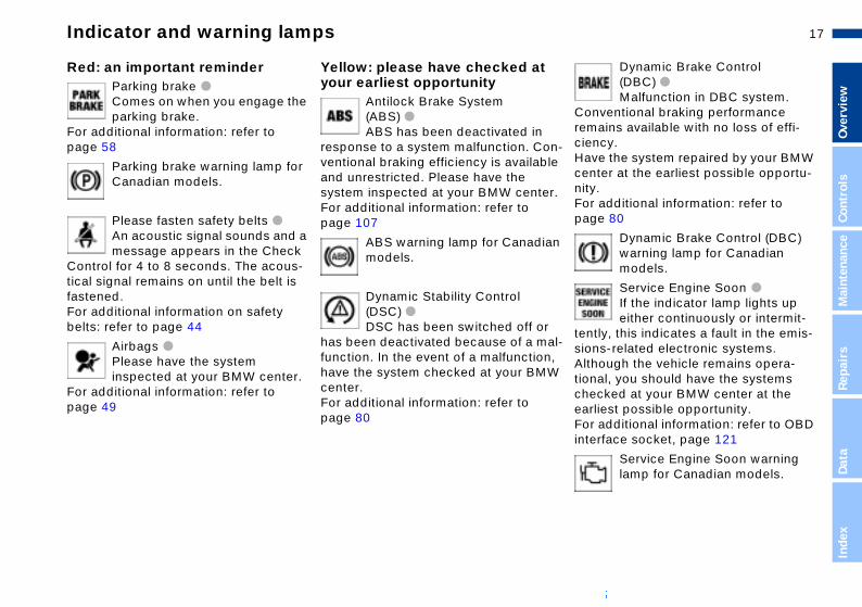
Malfunction in DBC system. ventional braking performance ains available with no loss of effi-cy. e the system repaired by your BMW ter at the earliest possible opportu-. additional information: refer to e 80
Dynamic Brake Control (DBC) warning lamp for Canadian models.
Service Engine Soon
●
If the indicator lamp lights up either continuously or intermit-
ly, this indicates a fault in the emis-s-related electronic systems.
n-le
r.
an
r al-
ConremcienHavcennityForpag
tentsion
Repa
irDa
taIn
dex
ough the vehicle remains opera-al, you should have the systems cked at your BMW center at the iest possible opportunity. additional information: refer to OBD rface socket, page 121
Service Engine Soon warning lamp for Canadian models.
n, W
AlthtioncheearlForinte
Red: an important reminderParking brake ● Comes on when you engage the parking brake.
For additional information: refer to page 58
Parking brake warning lamp for Canadian models.
Please fasten safety belts ● An acoustic signal sounds and a message appears in the Check
Control for 4 to 8 seconds. The acous-tical signal remains on until the belt is fastened. For additional information on safety
Yellow: please have checked atyour earliest opportunity
Antilock Brake System (ABS) ●
ABS has been deactivated in response to a system malfunction. Coventional braking efficiency is availaband unrestricted. Please have the system inspected at your BMW centeFor additional information: refer to page 107
ABS warning lamp for Canadimodels.
Dynamic Stability Control (DSC) ●
belts: refer to page 44
Airbags ●
Please have the system inspected at your BMW center.
For additional information: refer to page 49
DSC has been switched off ohas been deactivated because of a mfunction. In the event of a malfunctiohave the system checked at your BMcenter. For additional information: refer to page 80

18n
Indicator and warning lamps
Green: for your informationTurn signal indicatorsFlashes when the turn signal indicators are on. Rapid
flashing: indicates a system malfunc-tion. For additional information: refer to page 59
Cruise control Lights up when system is on: available for operation via the
multifunction steering wheel. For additional information: refer to page 61
Front fog lamps
Blue: for your informationHigh beams Lights up when the high beamsare on as well as when the
headlamp flasher is activated. For additional information: refer to pages 59, 85
Lights up whenever you switch on the front fog lamps.
For additional information: refer to page 85

19n
Over
view
Cont
rols
Mai
nten
ance
Repa
irs
Data
Steering wheel with multifunction buttons
me
ise control: select a stored setting.
ise control: store and accelerate (+) ecelerate and store (–).
ise control: activate/interrupt/deac-te.
s-
ndn
n
t
Volu
Cru
Cruor d
Crutiva
Inde
x
The controls integrated within the multi-function steering wheel (MFL) have been designed to allow you to operate a number of accessories both quickly and safely, without taking your eyes from the road:
>Selected control functions for the radio along with CD and cassette player
> the cruise control>selected telephone functions* and>voice entry*.
The controls are active only when the corresponding systems and
accessories are switched on.<
Switch between phone and radio, casette and CD.
Forward:
>RadioPress briefly: station scan in FM baExtended pressure: search functio
>CDPress briefly: track scanExtended pressure: search functioin track
>CassettePress briefly: stop track scan or fas
Press briefly:Receive a phone call, initiate dialing, terminate a call.Extended pressure:Activate/deactivate voice entry.
forwardExtended pressure: fast forward
>PhoneScan personal phone book.
Reverse: functions as forward.

20n
Warning triangle
*
First-aid kit
*
Refueling
filler doorBefore filling the tank, shut off the engine. If you do not, fuel cannot
Fuel
394d
e729
ed into the tank and the Service e Soon lamp may come on.<
en the filler door, press its front
lectrical malfunction occurs, you nlock the fuel filler door manually:
e the handle to lower the trim el on the right side of the luggage partment
l the button with the fuel pump bol.
be fillEngin
To opedge.
If an ecan u
1. Uspancom
2. Pulsym
The hazard warning triangle is readily accessible. It is stored in the container for the onboard tool kit mounted in the luggage compartment lid.
394d
e053
Under the front passenger's seat.
To remove: lift the button on the front (arrow) and pull the first-aid kit forwardout of its support.
390d
e716
To open the container, loosen the wingnut(s).
Always observe all legal regula-tions requiring a warning triangle
to be carried in the vehicle.<
To store: position the first-aid kit in thesupport, then push back until the buttonengages.
Some of the articles contained in the first-aid kit have a limited
storage life and should be replaced at periodic intervals. Please check the expiration dates of each of the items regularly, and replace any whose expiration dates have passed. You canacquire replacements in any drugstoreor pharmacy.Always observe all legal regulations requiring a first-aid kit to be carried in the vehicle.<

21n
Over
view
Cont
rols
Mai
nten
ance
Repa
irs
Data
Refueling
Refill early to avoid damaging the catalytic converter; never attempt
rive to the last drop of fuel in the .<
k capacity: approx. 18.5 gal. liters), with reserve of approx. gal. (10 liters).
Close the fuel filler cap carefully after refueling until a click is
rd. While closing, be sure not to eeze the strap which is fastened to cap. A loose or missing cap will vate the message "CHECK FILLER " in the Check Control.<
toel pt p, .<
he g
or
to dtank
Tan(70 2.5
heasquthe actiCAP
Inde
x
p-
Always observe all safety notices posted at the service station when
refueling. Never carry spare fuel con-tainers in your vehicle. Whether empty or full, these containers can leak, cause an explosion, or lead to fire in the event of a collision.<
Simple and environmentally friendly
Open the fuel filler cap carefullyprevent fuel from spraying out. Fu
394d
e120
spray may cause injury. Do not attemto continue adding fuel to the last droas this practice can cause fuel to spill
Keep the fuel filler cap in the bracketattached to the fuel filler door.
When refueling, insert the filler nozzlecompletely into the filler pipe. Pulling tnozzle out of the pipe during refuelin
> results in premature pump shutoff>and will reduce the effect of the vap
recovery system on the pump.
As long as the filler nozzle is used proerly, the fuel tank is full whenever thenozzle shuts off the first time.

22nFuel specifications Tire inflation pressure
Check tire inflation pressures on a regular basis, at least every two s, and before every extended y. Otherwise, incorrect tire pres-an lead to driving instability, tire ge and accidents.<
ply with tire approval ificationsflation pressures in the table
to BMW approved tire sizes and anufacturers. Your BMW center is ar with these pressures. Higher ures may be specified for tires by other manufacturers.
vehicle is equipped with tires
weekjournesure cdama
ComspecThe inapplytire mfamilipressmade
Your
not only meet US standards, but uropean standards. We recom- the exclusive use of BMW ved tires.whichalso Emendappro
The engine uses lead-free gasoline only.
Required fuel:
>Premium Unleaded Gasoline, min. 91 AKI.AKI = Anti Knock Index
Never use leaded fuel, as it would cause permanent and irreparable
damage to both the oxygen sensor and the catalytic converter.<
The inflation pressures are indicated on a warning sticker attached to the B-pillar behind the driver's door (visiblewith door open).
390d
e697
Check tire pressuresAll pressure specifications are indicatedin psi (kilopascal) for tires at ambient temperature (refer also to the next page).
After correcting the inflation pres-sures in the tires, reactivate the
Flat Tire Monitor, refer to page 82.<

23n
Over
view
Cont
rols
Mai
nten
ance
Tire inflation pressure
))
Repa
irs
Data
Inde
x
BMW TiresAll pressure specifications in the table are indicated in psi (kilopascal) with cold tires (cold = ambient temperature)
M5245/40 ZR 18 35 (240) - 44 (300) -275/35 ZR 18 - 38 (260) - 48 (330235/45 R 17 94 H M+S 35 (240) 38 (260) 39 (270) 46 (320

24n
Controls

25n
Over
view
Cont
rols
aint
enan
ce
Overview
Controls and features
Operation, maintenance
MRe
pair
sDa
tade
x
Owner service procedures
Index
Technical data
In

26nKeys Central locking system
onceptentral locking system is ready for tion when both front doors are d. The system engages and es the locks on the rsage compartment lid
l filler door.
entral locking system can be ted outside via the driver's door lock ell as via the remote control inside via the central locking
tem button.
el filler door is not locked when
The cThe coperaclosereleas>doo> lugg> fue
The copera> from
as w> from
sys
The fu
pen the vehicle from the inside to page 31). The anti-theft system omatically armed whenever you te the central locking system from e of the vehicle. Both the door and release handles remain d. The alarm system is also acti- or deactivated.you o(refer is autactivaoutsidlocks lockevated
1 The master keys with remote control determine the functions of the Key Memory. Refer to page 55.You can mark individual keys for sub-
463d
e023
2 Spare key for storage in a safe placesuch as in your wallet. This key is notintended for continuous use
3 Door and ignition keyThe lock for the glove compartment cannot be operated with this key. This is recommended for valet parking, for instance
sequent identification by applying the colored decals that you received when accepting delivery of your vehicle
There is an extended-life battery in every master key that is
charged automatically in the ignition lock as you drive.For this reason, if you have a master key that is not in regular use, you should use that key approx. once every year while driving for an extended period to charge the battery. For addi-tional information refer to page 28.<

27n
Over
view
Cont
rols
Mai
nten
ance
Central locking system Opening and closing – via the door lock
nvenience operation can also operate the electric power dows and the sliding/tilt sunroof via door lock.
o open: with the door closed, turn e key to the "Unlock" position and
old ito close: with the door closed, turn e key to the "Lock" position and
old it.
Watch the closing process care-fully and be sure that no one is
ped by the closing motion. easing the key stops the opera-.<
or
s
CoYouwinthe
>Tthh
>Tthh
trapReltion
Repa
irs
Data
Inde
x
nual operation he event of an electrical malfunc-)
n the key all the way to the extreme or right to unlock/lock the driver's r.
e or.
:
s)
Ma(in ttion
Turleft doo
When you use the central locking system to lock the doors from inside the vehicle, it will automatically disen-gage the locks if an accident occurs, except on doors that have been locked individually using the lock buttons, refer to page 31. The accident response rou-tine also includes automatic activation of the hazard warning flashers and the interior lamps.
Using the key One turn of the key in the driver's dolock unlocks the driver's door only. Turning the key a second time unlock
390d
e723
all of the remaining doors, the luggagcompartment lid and the fuel filler do
Vehicles without armored glassdo not lock the vehicle if anyone
will be remaining inside, as it would then be impossible for the occupant(to disengage the locks from the inside.<
You can have a signal set as anacknowledgment message that
the vehicle is locked correctly.<

28n
Opening and closing – via the remote control
er keys with remote control
Since passengers or animals remaining in the vehicle might be o lock the doors from the inside, he vehicle's keys with you so that hicle can be opened again from tside at any time.
<
Master keys that are used repeat-edly are always ready for opera-ince the battery in the key is ed automatically in the ignition s you drive. no longer possible to unlock the le via the remote control, the y is discharged. Use this key driving for an extended period in to recharge the battery. For more ation refer to page 26. nt unauthorized use of the remote l by surrendering e.g. only the nd ignition key 3 or the spare
(refer to page 26) when leaving hicle for valet parking. event of a system malfunction, e contact your BMW center, which your source for replacement
-
Mast
able ttake tthe vethe ou
tion, scharglock aIf it isvehicbatterwhile orderinformPrevecontrodoor akey 2the veIn thepleasis alsokeys.<
The conceptThe remote control gives you an excep-tionally convenient method for unlocking and locking your vehicle. Fur-thermore, it provides two additional functions that can only be executed by means of the remote control:
>To switch on interior lamps, refer to page 29With this function, you can also "search for" your vehicle – when parked in an underground garage, for instance
>To open the luggage compartment lid, refer to page 29The luggage compartment lid will
1 Unlock, convenience opening and alarm system
2 Lock and secure, interior lamp activation, disarming tilt alarm sensor and
390d
e793
open slightly, regardless of whether it was previously locked or unlocked
>Panic mode, refer to page 29In case of danger, you can trigger an alarm.
When you unlock (lock) your vehicle the system automatically deactivates (acti-vates) the anti-theft system and disarms (arms) the alarm system while also switching on (off) the interior lamps.
You can have a signal set as an acknowledgment message that
the vehicle is locked correctly.<
interior motion sensor3 Open the luggage compartment lid,
panic mode

29n
Over
view
Cont
rols
Mai
nten
ance
Repa
irs
Data
x
Opening and closing – via the remote control
open the luggage partment lid
ss button.
luggage compartment lid will open htly, regardless of whether the lid previously locked or unlocked.
Before and after a trip, be sure that the luggage compartment lid
not been opened unintentionally.<
ic mode
vided that the alarm system is ed, you can respond to imminent ger by holding down the button for een two and five seconds.
ancel alarm
ss button.
: e
s)
or
.
To com
Pre
Thesligwas
has
Pan
Proarmdanbetw
To c
Pre
Inde
To unlock
Press button.
Press the button once to unlock the driver's door and the fuel filler door only; press a second time to unlock all remaining doors as well as the luggage compartment lid.
Convenience opening mode
Press and hold button to open the elec-tric power windows and sliding/tilt sun-roof.
To lock and secure
Press button.
Vehicles without armored glassDo not lock the vehicle if anyon
will be remaining inside, as it would then be impossible for the occupant(to disengage the locks from the inside.<
To deactivate the tilt alarm sensand the interior motion sensor
Press button a second time immedi-
ately after locking.For additional information: refer to page 36.To switch on the interior lamps
With the vehicle locked, press button

30nOpening and closing – via the remote control
l
For US owners onlyThe transmitter and receiver units comply with part 15 of the FCC (FederaCommunications Commission) regula-tions. Operation is governed by the following:
FCC ID: LX8EWSLX8FZVSLX8FZVE
Compliance statement:This device complies with part 15 of theFCC Rules. Operation is subject to thefollowing two conditions:
>This device may not cause harmful interference, and
External systemsExternal systems or devices may cause local interference in the functions of the remote control.If this should occur, you can unlock and lock the vehicle via the door lock with a master key.
> this device must accept any interfer-ence received, including interferencethat may cause undesired operation.
Any unauthorized modifications to these devices could void the
user's authority to operate the equip-ment.<
31n
Over
view
Cont
rols
Mai
nten
ance
Repa
irs
Opening and closing – from the inside
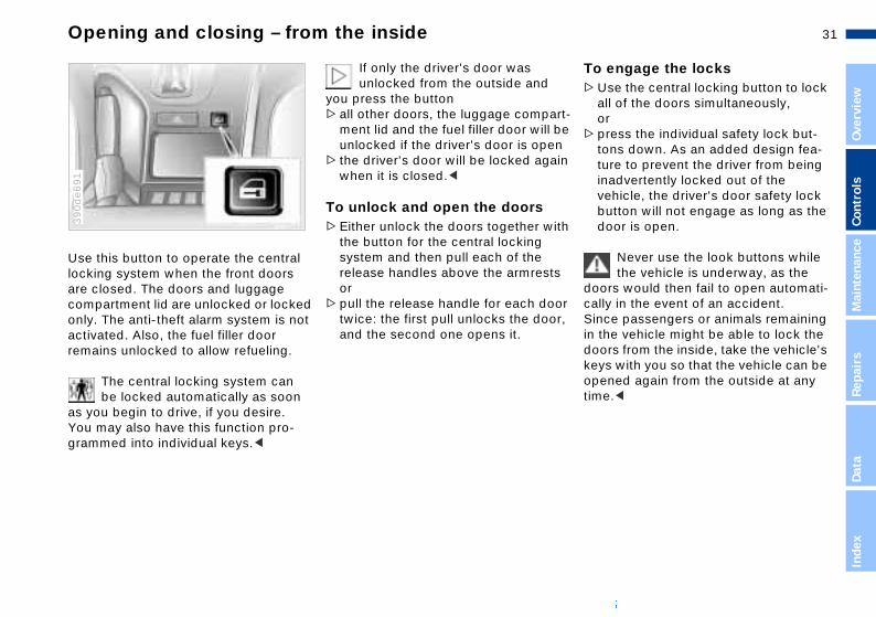
engage the locksse the central locking button to lock ll of the doors simultaneously, rress the individual safety lock but-ns down. As an added design fea-re to prevent the driver from being advertently locked out of the
ehicle, the driver's door safety lock utton will not engage as long as the oor is open.
Never use the look buttons while the vehicle is underway, as the
rs would then fail to open automati-y in the event of an accident.e passengers or animals remaining e vehicle might be able to lock the rs from the inside, take the vehicle's s with you so that the vehicle can be ned again from the outside at any .<
rt-be nin
ith
s
or r,
To >U
ao
>ptotuinvbd
doocallSincin thdookeyopetime
Data
Inde
x
Use this button to operate the central locking system when the front doors are closed. The doors and luggage compartment lid are unlocked or locked only. The anti-theft alarm system is not
390d
e691
If only the driver's door was unlocked from the outside and
you press the button>all other doors, the luggage compa
ment lid and the fuel filler door will unlocked if the driver's door is ope
> the driver's door will be locked agawhen it is closed.<
To unlock and open the doors>Either unlock the doors together w
the button for the central locking system and then pull each of the release handles above the armrestor
>pull the release handle for each dotwice: the first pull unlocks the doo
activated. Also, the fuel filler door remains unlocked to allow refueling.
The central locking system can be locked automatically as soon
as you begin to drive, if you desire. You may also have this function pro-grammed into individual keys.<
and the second one opens it.

32nLuggage compartment lid
al operation event of an electrical malfunc-
he master key to the left in the ge compartment lock all the way stop – the luggage compartment l open slightly.
ggage compartment is locked as soon as you close the lid.
Manu(in thetion)
Turn tluggato thelid wil
The luagain
The lock Only the master key (refer to page 26) fits in the lock for the luggage compart-ment lid.
394d
e783
To secure separatelyTurn the master key to the right past thepressure point and then pull it out in thehorizontal position.
394d
e731
To open separatelyTurn the master key to the left in the luggage compartment lock, continuing until it stops – the luggage compart-ment lid will open slightly.
The luggage compartment is locked again as soon as you close the lid.
This locks the luggage compartment and disconnects it from the central locking system. This feature can be used to prevent unauthorized access tothe luggage compartment when you hand over the door and ignition key 3 (refer to page 26) for valet parking, etc.

33n
Over
view
Cont
rols
Mai
nten
ance
Repa
irs
Luggage compartment lid
close handle recess (arrow) next to the mechanism is designed to assist in closing the luggage compart-t lid.
Operate the vehicle only when the luggage compartment lid is
pletely closed. An open lid would w exhaust fumes to penetrate into interior of the vehicle. Should it be olutely necessary to operate the
as To Thelockyoumen
comallothe abs
394d
e128
Data
Inde
x
icle with the luggage compartment pen:lose all windows. Shut the sliding/lt sunroofet the automatic climate control for aximum airflow, refer to page 89.<
vehlid o>C
ti>S
m
To open from the outsidePress the button (arrow): the luggage compartment lid opens slightly.
The luggage compartment is illumi-
394d
e728
To open from the insideProvided the luggage compartment hnot been locked separately, you can use this button to open it when the
39m
de1
17
nated when the luggage compartment lid is opened.
vehicle is stationary.

34nLuggage compartment lid Luggage compartment
er*e left-hand side of the luggage artment is a hanger for fastening ing bags, packages and similar
HangOn thcompshopp
394d
e144
.
, . itemsEmergency releaseThis lever releases the luggage com-partment lid from the luggage compart-ment's interior.
390d
e792
Luggage netUse the luggage net to secure smaller items of luggage.
39m
de0
50
If you place objects on the luggage netthis helps to prevent them from moving
Lashing eyes for attaching flexible straps* to secure your luggage are located in the corners of the luggage compartment.Refer also to "Cargo loading" on page 102.

35n
Over
view
Cont
rols
Mai
nten
ance
Alarm system
icator lamp displayshe indicator lamp below the interior arview mirror flashes continuously: e system is armed
ed e
-rm
d
Ind>T
reth
39m
de0
84
Repa
irs
Data
Inde
x
he indicator lamp flashes during rming: a door (or doors), the hood, ggage compartment lid or rear indow are not completely closed. ven if you do not respond by ecuring the indicated area, the ystem will start monitoring all other reas, and the indicator lamp flashes ontinuously after 10 seconds. How-ver, the interior motion sensor is not ctivated the indicator lamp goes out when e system is disarmed: no manipula-
on or attempted intrusions have een detected in the period since the ystem was armed
he in.
>TaluwEssacea
> Ifthtibs
The conceptThe vehicle alarm system responds:
>When a door, the hood or the lug-gage compartment lid are opened
>To movement inside the vehicle (inte-rior motion sensor)
>Variations in the vehicle's tilt angle of the kind that occur during attempts to steal the wheels or tow the vehicle
>To interruption of battery voltage.
The system responds to unauthorized vehicle entry and attempted theft by simultaneously activating the following:
>Sounding an acoustical alarm for 30 seconds
>The hazard warning flashers are acti-
To arm and disarm the alarm systemWhen the vehicle is locked or unlockwith the key or the remote control, thalarm system is also simultaneously armed or disarmed.
You can have different acknowledgment messages set to confi
arming and disarming.<
You can also open the luggage com-partment lid when the system is armeby pressing the button on the remote
vated for approx. five minutes>The high beams flash on and off in
the same rhythm as the hazard warning flashers.
control (refer to page 29). When you close the luggage compartment lid, tluggage compartment is secured aga

36nAlarm system Electric power windows
en and close windowsition key position 1 and 2:
ress the rocker switch until you
f
To opIn ign
>Dep
390d
e055
l resistance: window continues moving for as as you maintain pressure on the
tchss the rocker switch beyond the ssure point: window moves automatically.ss the switch a second time to p the window.
feeThelongswi
>PrepreThePresto
> If the indicator lamp flashes for 10 seconds when the system is dis-armed: an attempted entry has been detected in the period since the system was armed.
Following triggering of an alarm, the indicator lamp will flash continuously.
Avoiding unintentional alarms The tilt alarm sensor and interior motion sensor may be switched off at the same time. You can do this to prevent an unintentional alarm from being trig-gered (in garages with elevator ramps, for instance), or when the vehicle is transported by trailer or train:
Interior motion sensorIn order for the interior motion sensor tofunction properly, the windows and sliding/tilt sunroof must be completely closed.
Nevertheless, you should deactivate the interior motion sensor (refer to "Avoiding unintentional alarms") if
>children or animals are left in the vehicle
> the windows or the sliding/tilt sunrooare being left open.
Actuate the lock (= arm the system) twice; in other words, press button 2 of the remote control twice in succession (refer to page 29). You may also actuate the locks twice with the key (refer to page 27).The indicator lamp lights up briefly and then flashes continuously. The tilt alarm sensor and the interior motion sensor are deactivated as long as the system is armed.

37n
Over
view
Cont
rols
Mai
nten
ance
Electric power windows
ety switchh the safety switch you can prevent rear windows from being opened losed via the switch in the rear pas-
ht tu-).
ed e
y.
an
SafWitthe or c
390d
e693
Repa
irs
Data
Inde
x
ger area (by children, for example).
Press the safety switch whenever children are riding in the rear of
vehicle. Careless use of the power dows can lead to injury.<
r e
r
sen
the win
After the ignition has been switched off:
>You can still operate the power win-dows as long as neither of the front doors has been opened. To open a window, press the switch beyond the pressure point.
When leaving the vehicle, always remove the ignition key from the
lock and remember to close the doors to prevent children from operating the power windows and injuring them-selves, etc.<
For convenience operation via the door lock or remote control, refer to page 27 or 29.
Despite this safety feature, be extremely careful to ensure that
the closing path of the window is notobstructed. Otherwise, an object mignot touch the contact strip in some siations (very thin objects, for instanceYou can disable this safety feature bypressing the switch beyond the pres-sure point and holding it.Because the power windows are sealat high pressure to prevent wind noiswhen closed, a powerful motor is required for efficient closing. When closing the windows, always be surethat they are not obstructed in any waUnsupervised use of these systems cresult in serious personal injury.
Safety featureA contact strip is located on the inside upper frame of each of the windows. If pressure is exerted against this contact strip while a window is being raised, the system will respond by stopping the window and then retracting it slightly.
Remove the ignition key to deactivatethe electric power windows wheneveyou leave the vehicle. Never leave thkeys in the vehicle with unsupervisedchildren. Never place anything that could obstruct the driver's vision on onext to the windows.<

38nSliding/tilt sunroof*
matic opening and closing the switch past the pressure briefly: the sunroof travels to the fully-closed or fully-open on.
automatic operations are:
h the sunroof open, press the tch briefly toward "Lift": the sun-f automatically extends to its fully-ed positionh the sunroof lifted, press the tch briefly toward "Open": the roof automatically opens all the .
ing the switch again stops the
AutoPresspoint eitherpositi
Other
>Witswiroorais
>Witswisunway
Press
n immediately.y featuresliding/tilt sunroof encounters ance at a point roughly past the e of its travel when it is closing, osing cycle is interrupted and the of will open again slightly.
, -
motio
SafetIf the resistmiddlthe clsunro
To prevent injuries, exercise care when closing the sliding/tilt
sunroof and keep it in your field of vision until it is shut.Before leaving the vehicle, switch off the electric sunroof mechanism by removing the ignition key. Do not leave children unattended in the vehicle with access to vehicle keys. The key can be used to start the engine and to operate vehicle systems such as the power sun-roof, etc. Unsupervised use of these systems can result in serious personal injury.<
For convenience operation via the door
Raising – opening – closingWith the ignition key in position 1 or higher, press the switch or slide it in thedesired direction until you feel resis-
39m
de1
38
lock or remote control, refer to page 27 or 29. tance.
When lifting, the headliner retracts sev-eral inches.
The headliner insert can not be closed with the sunroof in its
raised position.<
After the ignition has been switched offyou can still operate the sliding/tilt sunroof as long as no front door has been opened.

39n
Over
view
Cont
rols
Mai
nten
ance
Sliding/tilt sunroof*
nual operation e event of an electrical malfunction,
can also operate the sliding/tilt roof manually.
MaIn thyousun
390d
e376
Repa
irs
Data
Inde
x
emove the interior lamp, then reach to the exposed opening and press ut the coverse the Allen key from the onboard ol kit (refer to page 124) to turn the
liding/tilt sunroof in the desired irection.
y :
x.
1. Rino
2. Utosd
Despite this safety feature, be extremely careful to ensure that
the closing path of the roof is not obstructed. Remember that the safety mechanism may not be able to detect every kind of potential obstruction (very thin objects, for instance). You can dis-able this safety feature by pressing the switch beyond the pressure point and holding it.<
Sliding/tilt sunroof with glass moonroof insert*The options and control procedures are essentially the same as those previ-ously described for the sliding/tilt sun-roof. In order to open the raised roof,
Interruption in the electrical supplyAfter interruptions in the electrical supply (when the battery is discon-
39m
de1
39
press the control switch towards "Open" and maintain pressure until the roof has reached the desired position.
The headliner insert slides back some-what when you raise the sunroof, and retracts along with the sunroof panel when you slide it back. The insert then remains open, and you can slide it back and forth to adjust it whenever the sun-roof is not fully retracted.
nected, for instance), the sunroof maonly lift. To reinitialize the mechanism
1. Raise the sliding/tilt sunroof fully2. Press and hold the switch for appro
20 seconds.

40n
adjusting your seat, always rve the following precautionsNever try to adjust your seat while operating the vehicle. The seat respond with an unexpected ment, and the ensuing loss of le control could lead to an acci-Never ride with the backrest ed to an extreme horizontal angle rtant for front passengers to
ber), otherwise, there is a risk ou will slide under the safety belt accident, thus negating the pro-n the safety belt provides.t move the seats to the rear when hicle is at an extreme angle (on
Sitting safely Seats
For relaxed and fatigue-free driving you should select a seating position that reflects your personal requirements. Correct seating position combines with safety belts and airbags to enhance occupant safety in the event of an acci-dent. To ensure that the vehicle's safety systems provide you with optimal pro-tection, we request that you direct your careful attention to the following sec-tion.
For additional information on trans-porting children, refer to page 51.
Sitting safely with airbagsAlways maintain an adequate dis-
For airbag locations and additional information on airbags refer to page 49.
Sitting safely with safety beltNever allow more than one person to wear a single safety belt. Never
allow infants or small children to ride in a passenger's lap. Avoid twisting the belt while routing it firmly across the pelvis and shoulder, wear it as snugly against your body as possible. Do not allow the belt to rest against hard or fragile objects in your pockets. Do not route the belt across your neck, or run it across sharp edges. Avoid wearing bulky clothing and pull on the lap belt
e ramps or steep slopes, for ple). If you do so, the automatic belt height adjustment can be gaged.<
adjustmentW M sport seat, refer to page 41W comfort seat, refer to page 42d restraints, refer to page 43W active seat, refer to page 43
tance between yourself and the airbags. Always hold the steering wheel by the rim with the hands at the 9 and 3-o'clock positions to keep any chance of injury to hands or arms to an absolute minimum should the airbag be deployed. Never allow any objects, individuals or animals to obstruct the areas between passengers and airbags.Never use the front airbag's cover as a storage tray or support for objects of any kind. Never allow front passengers to rest their feet or legs on the airbag cover.<
periodically to retension it over your shoulders. In the event of a frontal impact, a loose lap belt could slide over the hips, leading to abdominal injury. In addition, the safety belt's restraint effectiveness is reduced if it is worn loosely. Expectant mothers should always wear their safety belts, taking care to position the lap belt against the lower hips, where it will not exert pres-sure against the abdominal area.<
For information on using the safety belts refer to page 44.
Whenobse
couldmovevehicdent. reclin(imporememthat yin an tectioDo nothe ve
garagexamsafetydisenSeat>BM>BM>Hea>BM

41n
Over
view
Cont
rols
Mai
nten
ance
BMW M sport seat
gh support ss switch: you can adjust the thigh port for maximum personal comfort.
r
ThiPresup
39m
de1
15
Repa
irs
Data
Inde
x
lp g
/
ur-
1 Tilt (driver's seat only)
2 Backward/forward adjustment
3 Cushion height
4 Backrest angle
39m
de0
09
Lumbar support You can adjust the backrest's contoufor additional support in the curvatureof your spine's lumbar region.
39m
de1
14
5 Head restraint height
To adjust the angle of the head restraint manually, tilt to the desired angle.
Please refer to the adjustment instructions on page 40 to reduce
the risk of personal injury.<
The upper hips and spinal column receive supplementary support to heyou maintain a relaxed, upright seatinposition.
>Press front/rear of switch: increasedecrease curvature
>Press the upper/lower end of the switch: increase the upper/lower cvature.

42nBMW comfort seat*
passenger's seat adjusted for d traveling:
just the upper backrest section ts extreme rear positioner the backrest slightly to
rease the tilt angleng the upper backrest section
ard until your shoulders enjoy support.
Make corrections in the forward/backward adjustment of the seat ure that the safety belt still fits
against your body. Failure to ve this precaution can reduce the nt of protection provided by your
Front relaxe
1. Adto i
2. Lowinc
3. Briforwfirm
to ensfirmlyobseramou
belt.<
-safety
This seat also allows you to make addi-tional adjustments using the power seat system (refer to BMW M sport seat, page 41) for
380d
e024
Shoulder supportPress the switch: the support angle of the upper backrest section is adjusted.
530d
e252
1 Lumbar support
2 Shoulder support
Please refer to the adjustment instructions on page 40 to reduce
the risk of personal injury.<
Lumbar supportRefer to BMW M sport seat on page 41.
You can use the adjustable upper backrest for supplementary support in the shoulder region. This provides a relaxed seating position and helps relieve stress on the shoulder muscles.
To obtain the optimal shoulder supportposition, we recommend:
Driver and front passenger:
1. Adjust the upper backrest section toits extreme rear position
2. Adjust for the optimal seating posi-tion as described on page 40
3. Bring the upper backrest section forward until your shoulders enjoy firm support.

43n
Over
view
Cont
rols
Mai
nten
ance
Head restraints BMW active seat*
n .
Repa
irs
Data
Inde
x
Head restraints To adjust the angle of the front head restraints: tilt the head restraint.
To adjust the height of the rear head
39m
de1
31
Active changes in the seat's cushionhelps to avoid muscle cramps, pain ithe spine's lumbar region and fatigue
To activate, press the button.
39m
de1
21
restraints: pull up or push down.
Head restraints reduce the risk of spinal injury in the event of an
accident.Adjust the head restraint so that its center is approximately level with your ears.Leave the center-rear head restraint in the fully-lowered position at all times. Extending it limits its function.<

44nSafety belts
:
Drive with your safety belt onAlways fasten your safety belt before starting off. As supplemental restraint devices, the airbags are designed to
39m
de0
69
The shoulder belt anchor automaticallyadjusts to continue providing an optimum fit when you move the seat forward or back.
The rear belt buckle with the word"CENTER" is intended exclusively
for the passenger sitting in the middle.Vehicles with through-loading system*please refer to the instructions for usingthe rear center belt found on page 99.<
If the safety belt system has beensubjected to the stresses involved
in an accident or otherwise damaged: to ensure that the safety belts continue
enhance the effectiveness of the safety belts, and not to replace them.
To closeMake sure you hear the catch engage in the belt buckle.
To open1. Press the red button in the belt
buckle2. Hold the end of the belt3. Guide the belt back into the inertia
reel.
to provide effective protection, always have the entire safety belt mechanism replaced and the belt anchorages inspected at your BMW center.If a child-restraint system was in the vehicle during an accident, consult themanufacturer's instructions regarding replacement.<

45n
Over
view
Cont
rols
Mai
nten
ance
Repa
irs
Data
Inde
x
Seat, mirror and steering wheel memory
select a stored settingvenience function:
he driver's door remains open after nlocking or the ignition key is in osition 1riefly press memory button 1, 2 r 3, as desired.ovement stops immediately when ne of the seat adjustment or emory buttons is activated during e adjustment process.
ety function:
ith the driver's door closed and the nition key either removed or in osition 0 or 2aintain pressure on the desired emory button (1, 2 or 3) until the
djustment process is completed.
u should happen to press the MORY button by mistake: press the on a second time; the indicator p goes out.
Do not call up a position from the memory while the vehicle is
ing. There is a risk of accident from xpected movement of the seat or ring wheel.<
n
ng
di-
ut.
To Con
1. Tup
2. BoMomth
Saf
1. Wigp
2. Mma
If yoMEbuttlam
movunestee
You can store and call up three different seat, exterior mirror and steering wheel positions. The illustration shows the buttons on the driver's door for making these position adjustments.
390d
e032
To store1. Turn the key to ignition key positio
1 or 22. Adjust to the desired positions for
the seat, exterior mirror and steeriwheel
3. Press the MEMORY button: the incator lamp in the button lights up
4. Press memory button 1, 2 or 3, asdesired. The indicator lamp goes o
The setting for the lumbar support is not stored in memory.
46nSeat, mirror and steering wheel memory Seat heating
eat cushion and backrest can be d with the ignition key in on 2. You can select different g modes by repeatedly pressing ttons.
an also switch the higher heating s off directly: the button and hold it slightly r.
The sheatepositiheatinthe bu
You cmodePresslonge
390d
e720
Your BMW center can adjust your vehicle's systems in such a
manner that your personalized settings are automatically called up for the seat, mirror and steering wheel positions when you unlock the vehicle with your personal remote control key.<
Before using the key memory fea-ture to unlock the vehicle always
ensure that no objects are stored in the footwell behind the driver's seat. If you fail to do so, persons or objects could be injured or damaged if the seat should move backward.<
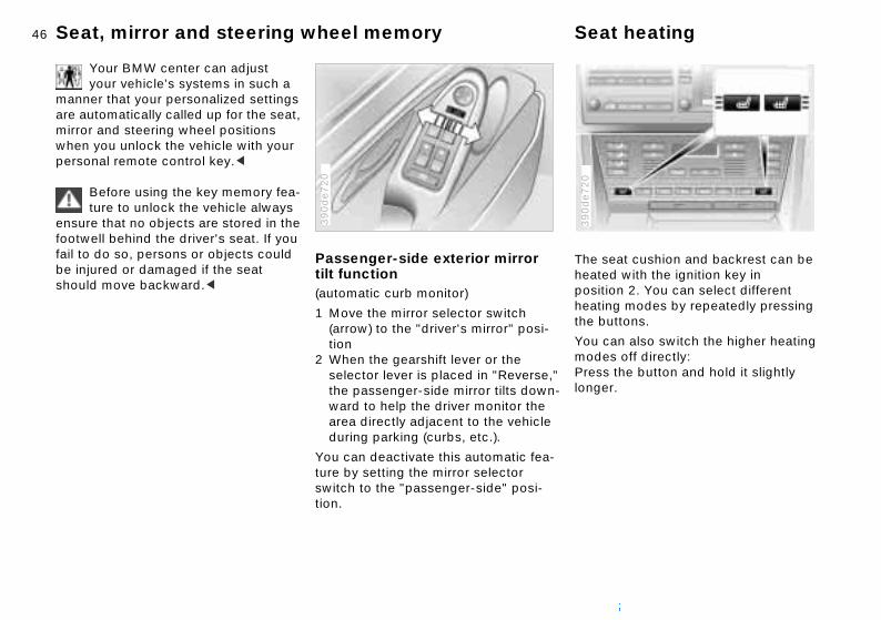
Passenger-side exterior mirror tilt function(automatic curb monitor)
390d
e720
1 Move the mirror selector switch (arrow) to the "driver's mirror" posi-tion
2 When the gearshift lever or the selector lever is placed in "Reverse,"the passenger-side mirror tilts down-ward to help the driver monitor the area directly adjacent to the vehicle during parking (curbs, etc.).
You can deactivate this automatic fea-ture by setting the mirror selector switch to the "passenger-side" posi-tion.

47n
Over
view
Cont
rols
Mai
nten
ance
Steering wheel
nd i-ry)
y
is g
Repa
irs
Data
Inde
x
AdjustmentsThe steering wheel can be moved in any of four directions. Adjust by moving the control lever in the desired direc-
39m
de1
34
Automatic steering wheel adjustmentIn order to make it easier to get into aout of the vehicle, the steering wheelautomatically moves into the top postion and returns to the driving (memoposition.
This automatic feature is controlled bthe position of the ignition key and bythe driver's door.
Your BMW center can adjust your vehicle's systems in such a
manner that your personalized settingautomatically called up for the steerinwheel position when you unlock the
tion.
Do not adjust the steering wheel while the vehicle is moving. There
is a risk of accident from unexpected movement.<
To store the steering wheel setting, refer to "Seat, mirror and steering wheel memory" on page 45.
vehicle with your personal key.<

48nMirrors
ior and exterior mirrors, atic dimming feature
mirrors automatically respond re from following vehicles by dim-
InterautomTheseto gla
39m
de0
82
through an infinitely variable . The mirrors automatically revert ir clear, undimmed setting when-ou select reverse.
terior rearview mirror's dimming on is regulated by two photocells; integrated in the mirror's lens ), while the other is located at an
position on the rear of the mirror.
sure that the mirror continues rate efficiently, ensure that the djacent to the photocells remains and unobstructed. Refrain from ing stickers or other objects to hield immediately behind the ew mirror.
ming rangeto theever y
The infunctione is(arrowoffset
To ento opearea aclear attachwindsrearvi
Exterior mirrors1 Switch for 4-way adjustment
2 Selector switch for changing
390us7
33
Convex mirrorThe passenger-side mirror fea-tures a convex lens. When esti-
mating the distance between yourself and other traffic, bear in mind that the objects reflected in the mirror are closerthan they appear.<
Your BMW center can adjust your vehicle's systems in such a
manner that your personalized setting isautomatically called up for the mirror position when you unlock the vehicle with your personal remote control.<
Self-defrosting mirrors
between mirrorsTo adjust manuallyThe mirrors can also be adjusted by hand: Press the edge of the lens.
To store mirror settings, refer to "Seat, mirror and steering wheel memory" on page 45.
Both mirrors are automatically defrosted with the ignition key in position 2.

49n
Over
view
Cont
rols
Mai
nten
ance
Airbags
tem components include the uphol-ed surfaces on the steering wheel, rument panel, the trim panels on the t and rear doors and the roof braces ell as the sides of the headliner
ve the doors. er attempt to remove or dismantle steering wheel. nsure compliance with official ty regulations, always entrust dis-al of airbag generators to your BMW ter. Attempts to carry out service cedures undertaken by anyone r than specially-trained profes-als can result in system failure or esired airbag deployment, both of ch can lead to personal injury. If the
-y r W if
g
in
e-
Syssterinstfronas waboNevthe To esafeposcenproothesionundwhi
Repa
irs
Data
Inde
x
ags deploy in response to an acci-t, always remember to avoid all tact with system components, as are hot and can cause burns in the
iod immediately following deploy-t.<
All vehicle occupants should always sit upright and be properly
rained (infants and small children in ropriate child-restraint systems; er children and adults using the ty belts). Never let an occupant's d rest near or on a side airbag: the ting airbag could cause a serious or
e -ny e of er-
e g,
ith r
airbdencontheypermen
restapplargsafeheainfla
1 Front airbags on the driver and passenger sides
2 Head protection airbags on driver and passenger side (front and rear*)
39m
de0
84
The side airbags in the rear passenger area* of your vehicle ma
already have been deactivated, eitheat the time of manufacture or by a BMcenter. You may have them activatedyou desire to do so. Please contact your BMW center for additional infor-mation.<
For information on the correct seatinposition, refer to page 40.
The airbags will not be triggeredthe event of a minor accident, a
vehicle rollover or a collision from therear.<
Never apply stickers or adhesiv
3 Side airbags on driver and passengerside (front and rear*)
Protective effectThe front airbags help to protect the driver and passenger in the event of a head-on collision where the protection provided by the safety belt alone would not be adequate. The head protection airbags and side airbags help provide protection in the event of a collision from the side. Each of the side airbags is designed to help support the occu-pant's upper body.
backed objects of any kind to thairbag covers. Never attempt to reupholster the covers or modify them in away. If the airbags deploy in responsto an accident, if you note any signs system malfunction, or if you wish tohave any parts of the airbag passengrestraint system deactivated, always contact your BMW center, to whom wstrongly urge you to entrust all testinrepair and dismantling operations. Never attempt to modify or tamper weither the system's electrical wiring oany of its individual components.

50nAirbags
the right way a child should sit in d restraint when rear side airbags ) are provided.
This isa chil(arrow
380d
e637
fatal injury. Please note that the word "Airbag" imprinted on the door trim panel indicates the airbag's location.Accident research shows that the safest place for children in an automo-bile is in the rear seat. However, a child sitting in the rear seat and not properly restrained may place his or her head on or near the side airbag, if installed. For example, a child – even though belted – may fall asleep with his or her head against the side airbag. It may be diffi-cult for a driver to ensure that children in the rear seat will remain properly positioned at all times and do not place their heads on or near the side airbag.
Even when all these guidelines are fol-lowed, there is still a small residual riskof injuries to the face, hands and arms occurring in isolated instances. The ignition and inflation noise may provoke a mild temporary hearing loss in extremely sensitive individuals.
Airbag warning information is also pro-vided on the sun visors.
Therefore, we recommend that the rear-seat side airbags, if provided, be deactivated if you plan to transport chil-dren in the rear seat.The rear-seat side airbags may already have been deactivated, either at the time of manufacture or by a BMW center. Labels in the rear door opening should indicate the status of your rear- seat side airbags. If you are uncertain of their status, or wish to have the airbags activated or deactivated, please con-tact your BMW center.<

51n
Over
view
Cont
rols
Mai
nten
ance
Airbags Transporting children
mercially-available child-restraint tems are designed to be secured a lap belt or with the lap belt por- of a combination lap/shoulder belt. roperly or inadequately installed raint systems can increase the risk jury to children. Always read and w the instructions that come with system.
he g
-
y
y up
it
ComsyswithtionImprestof infollothe
Repa
irs
Data
Inde
x
-
e
This is the right way a larger child should sit wearing the safety belt when rear side airbags (arrow) are provided.
380d
e638
Indicator lampThe indicator lamp indicates toperational status of the airbasystem from ignition key posi
tion 1.
System operational:
>The indicator lamp comes on brieflthen goes out.
System malfunction:
>The indicator lamp fails to come on>The indicator lamp comes on briefl
before going out and then lighting again.
Please respond to any malfunctions in the system by immediately having
inspected at your BMW center; otherwise the airbag could fail to respond to an accident in which both the angland the severity of the impact would normally trigger airbag deployment.
52nTransporting children safely
Before installing any child-restraint device or child seat, e read the following: install a rearward-facing child-int system in the front passenger f this vehicle.ehicle is equipped with an airbag
emental restraint system for the assenger. Because the backrest
y rearward-facing child-restraint (of the kind designed for infants
1 year and 20 Ibs./9 kg) would be the airbag's deployment range, hould never mount such a device front passenger seat, since the t of the airbag against the child int's backrest could lead to s or fatal injuries.
necessary for a child (not an ) to ride in the front seat, certain utions should be taken. First, the passenger seat as far away
pleasNeverrestraseat oYour vsupplfront pon ansystemunderwithinyou sin theimpacrestraseriouIf it isinfantprecamove
from the instrument panel as possible.Child-restraint system with tether strap If you use a child-restraint system with a tether strap, three additional tether
380us1
23
Each seating position is fitted with a head restraint. Lift the head restraint and pass the tether strap between the head restraint and the seat back. It is
394au
003
anchorage points have been provided – refer to the arrows in the illustration. Depending on the location selected for seating in the rear passenger area, attach the tether strap to the corre-sponding anchorage point to secure the child-restraint system, as shown in the following illustration.
recommended to readjust the head restraint into the lowest possible posi-tion.
Adjust the tether strap according to thechild restraint manufacturer's instruc-tions.

53n
Over
view
Cont
rols
Mai
nten
ance
Repa
irs
Transporting children safely
CH child-restraint anchorage nts*CH: Lower Anchor and Tethers for ldren.
p the rear center lap belt into the kle with the word CENTER and then the belt away from the area where child restraint will be mounted.
Vehicles with through-loading
ild-
LATpoiLATCHi
Snabucpullthe
390d
e786
Data
Inde
x
system*: use the small lock mech-m to connect the two sections of center belt, refer to page 99.<
est -
-
.
anisthe
This important precaution is intended to maximize the distance between the airbag and the child. Older children should be tightly secured with a safety belt, after they have outgrown a booster seat that is appropriate for their age, height and weight.Younger children should be secured in an appropriate forward-facing child-restraint system that has first been properly secured with a safety belt. Never install a rearward-facing child-restraint system in the front passenger seat. We strongly urge you to carefully read and comply with the instructions for installation and use provided by the child restraint's manufacturer when-
Child-restraint installationAll of the rear belt retractors and the front passenger's safety belt can be locked for mounting and securing ch
365us1
46
ever you use such a device.Be sure that all occupants (of all ages) remain properly and securely restrained at all times.<
All rear seating positions in your vehicle meet the recommendations of SAE J1819, an industry-recommended prac-tice for securing child-restraint systems in motor vehicles.
restraint systems. A label with the appropriate instructions is located inthe immediate vicinity of the buckle latch of each safety belt.
Lock the safety beltExtract the entire length of the belt fromthe belt retractor. Allow the reel to retract the belt somewhat and engagthe buckle, then tighten the belt againthe child-restraint system. The retraction mechanism is now locked.
Unlock the safety beltRelease the buckle, remove the childrestraint device and allow the belt retractor to reel the belt completely in

54nTransporting children safely
-safety locks the key in the slot of a rear door nd turn it outward:
oor can now be opened from the e only.
.
ChildInsertlock a
The doutsid
390d
e698
The rear outer seating positions are provided with anchors for a LATCH child-restraint system. The illustrations show the right rear seat as an example.
394us7
50
Canadian models only:The anchorage points for the LATCH child-restraint system are marked with buttons.
394us7
49
The outer anchorage points for the LATCH child-restraint system are marked with small flags.
To attach the LATCH child-restraint system, your BMW
center will provide an installation guideThe guide, although not necessary for installation of a LATCH child-restraint system, will facilitate the installation and also help protect the vehicle's seating surfaces. Carefully read and comply with the safety precautions of the manufacturer.<

55n
Over
view
Cont
rols
Mai
nten
ance
Repa
irs
Vehicle Memory, Key Memory
mples for Key Memory:
ocks the vehicle when you start offutomatically adjusts the driver's eat, the exterior mirrors and the teering wheel position to your per-onal programmed settings when you nlock the vehiclehe automatic climate control ssumes your preset comfort settings hen you unlock the vehicle.
You will see this symbol through-out the Owner's Manual. It is to
ind you at appropriate places of the ings that are available to you.<
he s a
n -
ith le
t
e
Exa
>L>A
sssu
>Taw
remsett
Data
Inde
x
How the system functionsNo doubt you have reflected at one time or another on how great it would be if you could permanently configure
463d
e029
When your vehicle is unlocked with tremote control, the vehicle recognizethe individual user by means of a datexchange with the key, and makes adjustments accordingly.
In order for you to distinguish betweedifferent keys, colored decals are supplied together with the keys.
What the system can doYour BMW center can provide you wdetails on the capabilities of the VehicMemory and Key Memory systems. Afew examples follow below:
Examples for Vehicle Memory:
>Various signals as acknowledgmen
your vehicle's various features and adjustments to mirror your own indi-vidual preferences. In engineering your vehicle, BMW has incorporated a number of options for personal adjust-ment that can be programmed into your vehicle at your BMW center.The available configuration data fall into two categories, according to whether their primary orientation is the vehicle ("Vehicle Memory") or the individual ("Key Memory"). Provided that each person has a separate remote-control key, you can have your BMW center enter two personal adjustments for two different individuals into the system.
when locking or unlocking your vehicle
>Activates/deactivates the "Follow mhome" function.

56n
re startingage the parking brake
ve the gearshift lever to the neu- positionress the clutch pedal.
Do not allow the engine to run in enclosed spaces. The exhaust contain carbon monoxide, an ss and colorless, but highly toxic reathing the exhaust gases poses
treme health risk, and can lead to sciousness and death.t leave the vehicle unattended he engine running. An unattended le with a running engine repre-
Steering/Ignition lock Starting the engine
0 Steering locked
1 Steering unlocked
2 Ignition switched on
390d
e010
Steering unlocked Turning the steering wheel slightly to the right or left often makes it easier to turn the key from 0 to 1. Individual electrical accessories are ready for operation.
Starting engine Depress the clutch when starting the engine. A lockout prevents the engine from starting with the clutch engaged.
a potential safety hazard.<
3 Starting engineSteering locked The key can be inserted or removed in this position only.
An acoustic warning is sounded when you fail to remove the ignition key after opening the driver's door.
After removing the key, turn the steering wheel slightly to the left or right until the lock engages.
Befo>Eng>Mo
tral>Dep
gasesodorlegas. Ban exunconDo nowith tvehic
sents
57n
Over
view
Cont
rols
Mai
nten
ance
Starting the engine Switching off the engine
n the ignition key to position 1 or 0.
Do not remove the ignition key while the vehicle is still moving. If
do so, the steering will lock, making possible to steer the vehicle.
en you leave the vehicle, always ove the ignition key and engage the ring lock.ays engage the parking brake n parking on hills and inclined sur-s, as even first gear or reverse may provide adequate resistance to ng.<
lly e-t
he
o
g, es n
-
Tur
youit imWhremsteeAlwwhefacenot rolli
Repa
irs
Data
Inde
x
re t s,
-
Starting engineDo not press the accelerator pedal while starting the engine.
While it is important not to release the key prematurely, you should
also avoid allowing the starter to operate continuously for more than 20 seconds at a time. Release the igni-tion key immediately when the engine starts.<
Do not warm up the engine by allowing it to run with the vehicle parked. Instead, you should drive away immedi-ately while taking care to avoid high engine speeds until the engine warms
The engine's idle speed is automaticaregulated by the computerized enginmanagement system. A brief period ahigh idle is normal just after starting; tidle speed should gradually return tonormal as the engine warms. Shouldthe engine fail to revert to its normal idle speed after warming, a problem may exist: please refer the problem tyour BMW center.
To prevent the battery from discharginalways switch off any electrical devicnot in use, as well as the ignition whethe vehicle is not being driven.
Extended starting attempts, characterized by excessively fre
to its normal operating temperature.
If the engine does not start on the first attempt (the engine is very hot or cold, for instance):
>Press the accelerator pedal halfway down while engaging the starter.
Cold starts at extremely low tempera-tures of roughly +57 (–156) or below and at altitudes of over 3,300 ft (1,000 m):
>Allow the starter to turn somewhat longer (approx. 10 seconds) during your initial starting attempt.
quent or long periods with the starter engaged, can lead to catalystdamage.<
When driving, standing at idle, and parking the vehicle, take ca
to avoid contact between the exhaussystem and flammable materials (grashay, leaves, etc.). Such contact couldlead to a fire, resulting in serious personal injury and property damage.<

58nParking brake Manual transmission
shifting gears, always depress utch pedal all the way down, then the gearshift lever until it engages ely in the desired gear.
Whenthe clmovesecur
39m
de0
17
ill also need to depress the clutch starting the engine, as an auto- lockout prevents the starter from ting when the clutch is engaged.
the vehicle lighting is switched e shift pattern is illuminated on arshift lever.
When shifting gears in the 5th/6th-gear plane, be sure to press arshift lever to the right in order vent inadvertent selection of a n the 3rd/4th-gear plane.<
You wwhenmaticopera
Whenon, ththe ge
the geto pregear i
The parking brake is designed primarily to prevent the vehicle from rolling when it is parked. It operates on the rear wheels.
390d
e714
If, in exceptional circumstances, itshould be necessary to engage
the parking brake while the vehicle is inmotion, do not pull it with excessive pressure. Keep your thumb pressed against the release button while care-fully pulling the lever up to apply mod-erate pressure. Excessive pressure can lead to over-braking and loss of traction (fishtailing)at the rear axle. The brake lamps do not come on whenthe parking brake is applied. Always engage the parking brake when parkingon hills and inclined surfaces, as even first gear or reverse may not provide
To engageThe lever engages automatically when it is pulled up, and the "PARK BRAKE" (in Canada "P") indicator lamp comes on in the instrument cluster in ignition key position 2. Refer to page 17.
To releasePull up slightly on the lever, press the button and lower the lever.
adequate resistance to rolling.<
You can help prevent corrosion and maintain balanced braking by periodi-cally pulling up the parking brake levergently while coasting to a stop at a traffic light. Always check traffic condi-tions first to avoid posing a hazard to yourself or other road users.

59n
Over
view
Cont
rols
Mai
nten
ance
Manual transmission Turn signal/Headlamp flasher
or
Repa
irs
Data
Inde
x
he
Reverse Select only when the vehicle is com-pletely stopped. Press the gearshift lever to the left to overcome the resis-tance.
As you do this, the backup lamps will turn on automatically when the ignition key is in position 2.
Do not hold the vehicle in place on slopes by slipping or "riding" the
clutch. Use the parking brake instead. Riding the clutch causes the clutch assembly to wear out prematurely.<
1 High beam (blue indicator lamp)
2 Headlamp flasher (blue indicator lamp)
3 Turn signal indicator (green indicat39m
de1
35
lamp accompanied by periodic clicking sound from the relay)
To signal brieflyPress the lever up to but not beyondthe pressure point. It then returns to tcenter position when released.
If the indicator lamp and the clicking from the relay are both
faster than normal, one of the turn signal indicators has failed.<

60nWasher/Wiper system/Rain sensor
Turn the rain sensor off in auto-matic car washes. Failure to do so result in damage caused by ired wiper activation.<
al wipe the vehicle is stationary, the s automatically revert to intermit-ipe (not on vehicles with rain r).
wipe the vehicle is stationary, the s operate at normal speed (not on les with rain sensor).
ning windshieldystem sprays washer fluid against indshield and activates the wipers rief period.
sive cleaningsetting 5. In addition, an intensive-
couldundes
NormWhenwipertent wsenso
Fast Whenwipervehic
CleaThe sthe wfor a b
IntenAs in
washer fluid is first sprayed on indshield.
actionthe w
0 Wipers retracted
1 Intermittent mode or rain sensor*2 Normal wipe
39m
de1
36
Intermittent mode or rain sensor*Intermittent mode:
You can set the wipe interval to four stages with rotary dial 7.In addition, the wipe interval varies automatically depending on road speed.
Rain sensor:
The rain sensor is positioned on the windshield, directly ahead of the inte-rior rearview mirror.
To activate the rain sensor:Move the lever to position 1 with the ignition key in position 1 or higher. Thewipers travel once across the wind-
3 Fast wipe
4 Brief wipe
5 Cleaning windshield
6 Intensive cleaning
7 Rotary dial for control of the wipe interval in the intermittent mode or the sensitivity of the rain sensor
shield, regardless of the weather conditions.
You can leave the lever permanently inposition 1. Whenever the ignition key isin position 1 or higher, all you then needto do to activate the rain sensor is briefly turn the rotary dial 7.
To adjust the sensitivity of the rain sensor:Turn rotary dial 7.
To deactivate the rain sensor:Put lever in position 0.

61n
Over
view
Cont
rols
Mai
nten
ance
Washer/Wiper system Cruise control
activate the system
m ignition key position 2:ss the button and the indicator lamp he instrument cluster (refer to e 18) will come on. You can now the cruise control.
Do not use cruise control on twisting roads, when high traffic
sity prevents driving at a constant ed, or when the road surface is slick w, rain, ice) or loose (rocks or el, sand).<
deactivate the system
-
er
To
FroPreon tpaguse
denspe(snograv
To
Repa
irs
Data
Inde
x
ss button as often as needed until indicator lamp in the instrument ter goes out.
ise control is also deactivated when ignition key is in position 0.
speed stored in memory is deleted.
Prethe clus
Cruthe
The
Cleaning headlampsWhen the headlamps are on, they are also cleaned automatically every fifth time you activate "Cleaning windshield" 5 or "Intensive cleaning" 6.
Do not use the washers if there is any danger that the fluid will
freeze on the windshield, as your vision could be obscured. You can reduce this danger by adding a windshield washer antifreeze. Refer to page 115. Do not activate the washer if the reservoir is empty, as the washer pump could be damaged.<
Windshield washer jets
You can store and automatically maintain any desired vehicle speed aboveapprox. 20 mph (30 km/h).
The cruise control is available whenevthe engine is running and the systemhas been activated.
The windshield washer jets are warmed automatically when the ignition key is in position 2.

62nCruise control
terrupt the cruise control
the system is activated, press the . The indicator lamp stays on.
an use the cruise control again ever you want by calling up the that was stored last.
ition, cruise control is interrupted atically:
en the brakes are applied en you depress the clutch pedalu exceed or fall below the pro-
mmed speed for an extended iod (by depressing the acceler-r, for example).
To in
WhenbuttonYou cwhenspeed
In addautom
>Wh>Wh> If yo
graperato
call the stored setting
button:ehicle accelerates to and main-the last speed stored.
To re
PressThe vtains
To maintain and store speed or to accelerate
Press button (+) briefly:The system maintains and stores the current vehicle speed. Every time you tap the button, the speed increases by approx. 0.6 mph (1 km/h).
Press and hold button (+):The vehicle accelerates without pres-sure on the accelerator pedal. When you release the button, the system stores and maintains the current speed.
If, on a downhill gradient, the
To decelerate
Press button (–) briefly:If you are already driving with active cruise control, the speed is decreased by approx. 0.6 mph (1 km/h) every timeyou tap the button.
Press and hold button (–):With the cruise control active, the system automatically reduces the throttle opening to slow the vehicle. When you release the button, the system maintains and stores the cur-rent speed.
engine braking effect is not suffi-cient, the controlled speed can be exceeded. Speed can drop on uphill grades if the engine output is insuffi-cient.<

63n
Over
view
Cont
rols
Mai
nten
ance
arningoutside temperature drops to x. +37.5 7 (+3 6), a signal is ed as a warning and the display s for a brief period.
The ice warning does not alter the fact that surface ice can form at ratures above +37.5 7 (+3 6),
dges or shaded road surfaces, for ce.<
Odometer, outside temperature display
1 Odometer
2 Trip odometer
3 Outside temperature display
39m
us0
05
Outside temperature display The outside temperature appears in the display in ignition key position 1 and higher.
Repa
irs
Data
Inde
x
hange the units of measure-) by
and holding the button with the ignition key in 1the ignition key to 0.
Odometer You can activate the displays shown in the illustration with the ignition key in position 0 by pressing the button in the instrument cluster (arrow).
The range of available displays varies according to your individual vehicle's equipment.
Trip odometer To reset the trip odometer to zero, press the button (arrow) with the igni-tion key in position 1 or higher.
You can cment (7/6
1. pressing(arrow) position
2. turning
Ice wIf the approsoundflashe
tempeon briinstan

64nTachometer Engine oil temperature Fuel gauge
you switch on the ignition, the tor lamp comes on briefly to con-at the system is operational.
Whenindicafirm th
39m
us0
25
indicator lamp comes on and on, there are approx. 2.5 gal ers) of fuel still in the tank.
el tank capacity, refer to 143.
tilt of the vehicle varies (when you iving in mountainous areas, for ple), the needle may fluctuate ly.
Please refuel early, since driving to the last drop of fuel can result in ge to the engine and/or catalytic rter.<
If the stays (10 lit
For fupage
If the are drexamslight
damaconve
The orange pre-warning zone appears depending on the engine temperature. As the engine temperature increases, more and more of the sectors of this
39m
us0
23
The normal operating temperature range is between +176 7 (+80 6) and+248 7 (+120 6). Do not exceed themaximum temperature of +302 7
39m
us0
24
pre-warning zone disappear.
Avoid engine speeds in the pre-warning zone if possible.
Do not operate the engine with the needle in the red overspeed zone of the gauge.
To protect the engine, the engine-man-agement system interrupts the fuel supply when you approach this sector.
(+150 6).

65n
Over
view
Cont
rols
Mai
nten
ance
irs
Coolant temperature gauge Service Interval Display
en lamps number of illuminated lamps reases as the time for your next ntenance visit approaches.
low lamp field appears together with
GreThedecmai
YelThis
380us0
08
Repa
Data
Inde
x
SERVICE or INSPECTION.
ntenance is due. Please contact r BMW center for an appointment.
lamp maintenance deadline has been sed.
OIL
Maiyou
RedThepas
BlueThe engine is still cold. Drive at mod-erate engine and vehicle speeds.
39m
de0
26
RedAccompanied by the warning, "COOLANT TEMPERATURE" in the Check Control: the engine is over-heated. Shut off the engine immediately and allow it to cool down.
To check coolant level, refer to page 118.
Between the blue and red zonesNormal operating range. The needle may rise as far as the edge of the red sector in normal operation.

66n
ECK BRAKE FLUID" level has dropped nearly to the imum. Top up the brake fluid at earliest opportunity. Refer to e 118. Have the source of the ke fluid loss diagnosed and cor-ted at your BMW centerE DEFECT" uce vehicle speed immediately stop the vehicle. Avoid hard ke applications. Do not oversteer.er to page 83IT"* is displayed if the programmed ed limit has been exceeded. er to page 73.
Check Control
Text messages are used to alert the driver to system malfunctions with the ignition key in position 2 and higher. The alert is accompanied by a gong.
39m
us0
27
Priority 1
These defects are immediately indi-cated by a gong and a flashing warning symbol 1. Simultaneous defects will be
consecutively. These status remain in the display until thee corrected. They cannot be pressing the CHECK
SE PARKINGBRAKE"NT TEMPERATURE"lant is overheated. Stop the and switch off the engine tely. Refer to page 117NGINE OILPRESS"ressure is too low. Stop the
and switch off the engine tely. Refer to pages 16, 115
1 Status symbol for messages
2 Display
3 CHECK button
Messages warning of system malfunc-tions are assigned one of two priority levels.
displayed messagesdefects ardeleted bybutton 3:
> "RELEA> "COOLA
The coovehicle immedia
> "STOP!EThe oil pvehicle immedia
> "CHTheminthepagbrarec
> "TIRRedandbraRef
> "LIMThisspeRef

67n
Over
view
Cont
rols
Mai
nten
ance
Check Control
HECK BRAKE LININGS"ave the brake pads checked at your MW center. Refer to page 108HECK COOLANT LEVEL"
he coolant level is too low; top off t the next opportunity. Refer to age 118HECK FILLER CAP"
heck to see whether the fuel filler ap has been properly closed. Refer page 21 NGINE FAILSAFE PROG"dicates a malfunction in the elec-onic engine-management system, hich then reverts to an emergency efault program allowing continued peration at reduced power and
he its
r
ir-
> "CHB
> "CTap
> "CCcto
> "EIntrwdo
Repa
irs
Data
Inde
x
wer engine speeds.lease have the system inspected by our BMW center
UTSIDE TEMPERATURE 24 7 5.0 6)"his temperature display is only an xample. The current temperature is isplayed at outside temperatures of 7.5 7 (+3 6) and below. Refer also page 63.
loPy
> "O(–Ted3to
Priority 2
These displays appear for 20 seconds with the ignition key in position 2. The warning symbols remain after the mes-sage disappears. The messages can be recalled again with CHECK button 3.
> "TRUNKLID OPEN"This message appears only when you initially begin a trip
> "DOOR OPEN"This message appears after a defined road speed has been exceeded
> "FASTEN SEAT BELTS"*In addition to this message, an indi-cator lamp with the safety belt icon appears and an acoustic signal is
> "TIRE PRESSURE SET"The Flat Tire Monitor has adopted ttires' current inflation pressures as reference levels. Refer to page 82
> "TIRECONTROL INACTIVE" Transient malfunctions and systemerrors in the Flat Tire Monitor. Refeto page 83
> "CHECK BRAKE LIGHTS"A lamp has failed or the electrical ccuit has a fault. Refer to pages 126and 132 or consult a BMW center
> "CHECK LOWBEAM LIGHTS""CHECK SIDE LIGHTS""CHECK REAR LIGHTS""CHECK FRONT FOGLAMPS""CHECK LICPLATE LIGHT"
sounded> "WASHER FLUID LOW"
Too low; top up fluid at the next opportunity. Refer to page 115
> "CHECK ENGINE OIL LEV"The oil level is at the absolute min-imum, so add engine oil as soon as possible. Refer to page 115. Until then, do not drive more than approx. 30 miles (50 km)
"CHECK HIGHBEAM LIGHT""CHECK BACK UP LIGHTS"Defective bulb or circuit. Refer to page 124 and following and page 132 or consult a BMW center
68nCheck Control
Displays after completion of a tripAll of the malfunctions registered during the trip appear consecutively when the key is turned to position 0.
The following displays will appear when appropriate:
> "LIGHTS ON"This display appears when you open the driver's door after parking the vehicle
> "KEY IN IGNITION LOCK"> "CHECK ENGINE OIL LEV"
Add the engine oil at the earliest opportunity (next stop to refuel). Refer to page 115.
To check the Check ControlPress the CHECK button 3 with the ignition key in position 2: CHECK CONTROL OK appears in the display.
There are no faults in the monitored systems.
ComputerYou can find descriptions of the com-puter starting on page 73 and in the "Owner's Manual for Onboard Com-puter."
You can have the Check Control
Status messages remain available for a period of approx. three minutes after the display goes out and the key is removed from the ignition. Press the CHECK button 3 to display these mes-sages. If there were multiple messages, press the CHECK button repeatedly to view them all in sequence.
and computer messages dis-played in a different language.<

69n
Over
view
Cont
rols
Mai
nten
ance
Repa
irs
Multi-Information Display (MID)
play for the entry and query but-s. Depending on the operating de, the functions and alternatives ch can be selected at the buttons displayed here
ry and check buttons for operating various onboard systems
-
6 Distonmowhiare
7 Entthe
Data
Inde
x
Central DisplayThe MID serves as the central display and control for the following onboard systems:
>Digital clock (e.g. time display, date)>Audio systems (radio, cassette, CD)>Computer (e.g. fuel consumption,
cruising range)>Cellular phone (e.g. dialing).
You will find explanations and notes for operating the digital clock and the com-puter on the following pages. Please refer to the Owner's Manual for oper-ating the audio systems, the cellular phone and the onboard computer.
1 Function button for audio systems
2 Function button for the cellular phone*
390us7
05
The system rejects all implausible data entries.
All stored data will be lost if the power supply is interrupted. Time of day, switch-on times for parked-car ventila-tion, distance and cruise control speed limit may have to be reset once the power supply has been re-estab-lished.<
3 Indicator lamp for parked-car ventilation system> remains on if switch-on time is
active> flashes while operating
4 Function button for the digital clock and computer
5 Indicator display for the various onboard systems

70nDigital clock
ging the date
the left side of the button.
.
the right side of the button:ots and the DATE display will
er the setting:
Chan
Press
Press
PressThe dflash.
To alt
on left or right, or hold the button .
re the entry:
the right side of the button.
lock takes leap years into account erefore does not have to be reset
ally.
Pressdown
To sto
Press
The cand thmanu
Only make entries when the vehicle is standing still – to avoid
endangering yourself or other road users.<
Calling up time or date
Press the left side of the button.
Display shows:
You can have the time of day displayed in 12 or 24 hours.
Changing the time
Press the left side of the button.
Press the right side of the button:The dots flash in the display.
To alter the setting:
Press on the left or right, or hold the button down.
To change the display:
Press the left side of the button.
If the 12-hour time display is in use, AM or PM appears after the time.
To store the entry:
Press the right side of the button.

71n
Over
view
Cont
rols
Mai
nten
ance
Digital clock
tart the stopwatch:
ss the right side of the button.
ake an intermediate time reading:
ss.
ss: stopwatch display can be seen nting up; the stopwatch continues
To s
Pre
To t
Pre
PreThecou
Repa
irs
Data
Inde
x
un.
alt the stopwatch:
ss the right side of the button.
The stopwatch is halted when the ignition key is turned back to 0,
starts to run again when the ignition is turned to 1.<
to r
To h
Pre
but key
Reminder signalYou can program an hourly reminder signal (Memo), that will, for example, remind you of news broadcasts.
Press the left side of the button.
Press:MEMO OFF appears in the display for entry and query buttons, and the tone symbol will appear in the upper right of the display.
A signal is then heard 15 seconds
Stopwatch
Press the left side of the button.
Press.
Display shows:
before each hour.

72nDigital clock
tivate/deactivate the time:
twice.
ing the parked-car ventilation m on and off directly
The parked-car ventilation system is available exclusively in ignition osition 1.<
the left side of the button.
To ac
Press
Turnsyste
key p
Press
.
lPress
or
press
Setting activation times for parked-car ventilation systemYou can enter two different activation times. After 30 minutes, the ventilation will switch off automatically.
Please observe the instructions for operating the parked-car venti-
lation system on page 92.<
Press the left side of the button.
To enter the time:
Press on left or right, or hold down.
To confirm the entry:
Press the right side of the button.
The activated time is marked with an asterisk.
The switch-on times remain memorized
Press on the left or right.
Display shows:
Press the right side of the button:Display flashes, e.g. TIMER 1.
until new entries are made.
You can change switch-on times that have already been memorized by set-ting a new time using the procedure described above.
When the switch-on time is active, the LED comes on in the MID. During actuaoperation of the ventilation, the LED flashes. The LED goes out when the system is switched off.

73n
Over
view
Cont
rols
Mai
nten
ance
Computer
lay shows:
er the limit by pressing the function ons.
orrect an entry:
ss the left side of the button and eat the entry.
tore the entry:
ss the right side of the button.
he
n-ph
Disp
Entbutt
To c
Prerep
To s
Pre
Repa
irs
Data
Inde
x
Only make entries when the vehicle is standing still – to avoid
endangering yourself or other road users.<
Computer calculations begin at the start of the journey.Display information can also be accessed by remote control, refer to page 77.
Speed limitSpeed limit entry:
You can enter the road speed here at which you wish to hear and see a reminder signal: a signal will sound, tword LIMIT will flash and the stored speed will briefly flash in the Check Control display on the instrument cluster.
The speed limit reminder is only repeated if the vehicle has in the meatime been driven at least approx. 3 m(5 km/h) slower.
Press the right side of the button.
Press.
Press the right side of the button.

74nComputer
rrect an entry:
the left side of the button and t the entry.
re the entry:
the right side of the button.
all stored value:
the right side of the button.
To co
Pressrepea
To sto
Press
To rec
Press
the left side of the button.
Press
To adopt the current speed as the speed limit:
Press the right side of the button.
Press.
Press twice at right.
Deactivating the speed limit:
Distance to destinationThe remaining distance to the destina-tion will be displayed on the screen. This is of course only possible if you entered the entire distance before starting the journey.
Enter:
Press the right side of the button.
Press the left side of the button.
Press the right side of the button.
Press.
The LIMIT display goes out, but the stored limit is not lost and can be re-activated by pressing the LIMIT button.
Press the right side of the button.
Display shows:
You can enter the distance by pressingthe function buttons.

75n
Over
view
Cont
rols
Mai
nten
ance
Computer
l consumption can have the average fuel sumption displayed for two different ances, for example a complete ney and part of the journey.
tart the calculation, select the func- with the engine running:
ss the right side of the button.
ss on left or right: average fuel consumption will be cated in the display.
d k
to ,
FueYoucondistjour
To stion
Pre
PreTheindi
Repa
irs
Data
Inde
x
estart the fuel consumption calcula-:
ss on the left or right.
ss the right side of the button.
ld To rtion
Pre
Pre
Estimated time of arrivalWhen you have entered the distance from your destination, you can obtain an estimated time of arrival display which is continuously updated by the computer as your average rate of progress varies.
Press the right side of the button.
Press the right side of the button:The estimated time of arrival is dis-played.
Cruising rangeThe distance which the vehicle shoulcover on the remaining fuel in the tanis displayed.
Press the right side of the button.
Press:The display shows the estimated cruising range.
When there is only enough fuel drive less than 30 miles (50 km)
you should refuel, as otherwise the engine or the catalytic converter coube damaged.<<<<
The computer will only register fuel amounts over 1.8 gal (6 liters).

76nComputer
re the entry:
the right side of the button.he ignition key to position 0.
ivate the code:
you are asked to enter the code on key in position 1 or 2):
er the code at the function but-s
the right side of the button.
To sto
PressTurn t
Deact
When(igniti
>Entton
Press
the code has been entered cor- and confirmed with the SET , the time display appears.
After rectlybutton
SpeedYou can call up a display of the vehicle's average speed.
To start the calculation, select the func-tion with the engine running:
Press the right side of the button.
Press:The display shows the average speed.
To recalculate the speed:
Extended immobilizer functionYou can define a code that will preventthe engine from being started unless the code is entered.
If you do not have access to the code, the emergency deactivation procedurewill have to be carried out, refer to the next page.
To enter and activating the code:
Press the right side of the button.
Press the right side of the button.
Press the left side of the button.
Display shows:
Enter the code at the function buttons.
To correct an entry:
Press the left side of the button and repeat the entry.

77n
Over
view
Cont
rols
Mai
nten
ance
Computer
isplay all the available information, ss:
he button on the lever until the dis-lay shows PROG 1he SET button.
btain individual items of informa-, press the button in briefly as often ecessary.
-.
To dpre
>Tp
>T
To otionas n
Repa
irs
Data
Inde
x
1
ch
ro-ay.
:
After three incorrect code entries, or three attempts to start the engine without a code entry, the alarm will sound for 30 seconds on vehicles equipped with an alarm system.
Setting the alarm in an emergency:
If you have forgotten the code, proceed as follows:
1. Disconnect the battery, wait about 2 minutes, then reconnect it. Note that on vehicles with an alarm system, the alarm will sound
2. Turn the ignition key to position 1:The time display will count down for the next ten minutes
3. After ten minutes, start the engine.
Remote controlYou can press the button in the turn signal indicator lever to retrieve information from the computer for display
39m
de1
18
If the code becomes available again in the meantime, it can be
entered during the waiting period after pressing the CODE button.<
To do this, press:
>The button on the lever until PROGshows on the display
>The MID buttons in the order in whiyou wish the information to be dis-played.Each time an entry is stored, the pgram number appears on the displ
To terminate the selection procedure
Press the right side of the button.

78n
stic signalsistance from an obstacle is indi- in front with a higher intermittent at the rear with a lower intermit-ne. As the distance between
e and object decreases, the inter-etween the tones become shorter. tinuous tone indicates the pres-of an object less than 1 ft (30 cm)
arning signal is canceled after x. three seconds if you are g parallel to a wall.
e is a malfunction of the system:dicator lamp flashes and a brief
Park Distance Control (PDC)*
The conceptPDC provides extra safety and conve-nience during parking maneuvers by providing an acoustic signal to indicate the distance to the nearest object. To do this, four ultrasonic sensors in the front and rear bumpers each measure the distance to the nearest object. The monitoring range of the front sensors and two rear sensors at the ends of the rear bumper extends outward roughly 2 ft (60 cm), while the rear bumper's two centrally located sensors detect objects at distances of up to approx. 5 ft (1.50 m).
Manual activationPress the button, the indicator lamp lights up.
39m
de1
16
uous signal tone is heard
n you activate PDC with the tonn you select reverse for the first
e after switching on the ignitionmalfunction occurs while the PDC tem is active.
h the system off and have the of the malfunction corrected by MW center.
Automatic functionThe system is activated automatically about one second after you engage reverse with the ignition key in position 2.
When you subsequently drive a dis-tance of more than approx. 160 ft (50 meters) or exceed a speed of approx. 20 mph (30 km/h), the system switches off and the indicator lamp goes out. Switch the system on again as required.
Manual deactivationPress the button again.
AcouThe dcatedtone, tent tovehiclvals bA conence away.
The wappromovin
If therThe incontin
>whebut
>whetim
> if a sys
Switccauseyour B

79n
Over
view
Cont
rols
Mai
nten
ance
pair
s
Park Distance Control (PDC)*
ReDa
taIn
dex
PDC does not remove the driver's personal responsibility for evalu-
ating the distance between the vehicle and any obstacles. Even with the sen-sors, there is a blind spot in which objects cannot be detected. This applies especially in those cases where the system approaches the physical limits of ultrasonic measurement, as occurs with e. g. tow bars and trailer couplings, and in the vicinity of thin or wedge-shaped objects. Certain sources of sound, such as a loud radio, could drown out the PDC signal tone.<
Keep the sensors clean and free of ice or snow in order to ensure
that they will continue to operate effec-tively.Do not apply high-pressure spray to thesensors for a prolonged period of time.Maintain an adequate distance of morethan 4 in (10 cm).<

80nDynamic Stability Control (DSC)
activate the system the button again; the indicator goes out.
The laws of physics cannot be repealed, even with DSC. An priate driving style always ns the responsibility of the driver. t use the extra safety margins fur-
d by these systems as an excuse ing unnecessary risks.<
mic Brake Control (DBC)is an integral component of the ystem.
ystem responds to sudden, high-ity applications of force to the pedal by automatically braking hicle with maximum boost to
ve the shortest possible braking ces during "panic stops." This
To rePresslamp
approremaiDo nonishefor tak
DynaDBC DSC s
The sintensbrakethe veachiedistan
system exploits all the benefits of ABS.t reduce the pressure exerted st the brake pedal until the g maneuver has been completed.
is deactivated when you release dal.
s Do noagainbrakinDBC the pe
DSC maintains vehicle stability, even in critical driving situations.
The system optimizes vehicle stability during acceleration and when starting from a full stop, as well as enhancing traction. In addition, the system recog-nizes unstable vehicle conditions (understeering or oversteering, for example) and holds the vehicle on a sure course by intervening via the engine and by braking at the individual wheels.
The system starts up automatically each time you start the engine.
Indicator lamp
To deactivate the systemPress the button, the indicator lamp lights up and remains on continuously.
39m
de1
24
The indicator lamp in the instru-ment cluster goes out shortly after you switch on the ignition.
Refer to page 17.
Indicator lamp flashes:The system is active and governs drive and braking force.
If the indicator lamp fails to go out after the engine is started, or if it comes on during normal driving and stays on:There is a system malfunction or the system was deactivated with the button. You can continue to drive the vehicle normally, but without DSC. Please con-sult your BMW center for repairs.
When DSC is deactivated, you are driving with conventional power transfer.
In the following exceptional circum-stances, it may be effective to deacti-vate the DSC for a short period:
>When rocking the vehicle or starting off in deep snow or on loose surface
>When driving with snow chains.

81n
Over
view
Cont
rols
Mai
nten
ance
Repa
irs
M Dynamic Driving Control
Data
Inde
x
The system guarantees that whenever desired, the system will switch the Ser-votronic and the accelerator pedal response from the sporty-comfortable
39m
de1
25
Performance Recognition Press the button with the ignition key inposition 2: the indicator lamp comes on.
Deactivating Performance Recognition:Press the button again; the indicator lamp goes out.
The coordinated performance-comfort mode is activated automatically each time you start the engine.
mode to a pure performance mode. This means that steering response becomes more performance-oriented and the response of the accelerator pedal is much more spontaneous (Per-formance Recognition).

82nFlat Tire Monitor
at this process after altering the flation pressure, changing the tire, ating the wheels.
t carry out a new initialization of stem, if you correct the inflation ures to the already specified tire ures.
Repetire inor rot
Do nothe sypresspress
The conceptThe Flat Tire Monitor keeps track of the inflation pressures in your tires as you drive. The system provides an alert whenever the inflation pressure drops significantly in one of the tires.
To initialize the Flat Tire Monitor system with the correct tire inflation pressures, start by checking the inflation pressures in all four tires, comparing them with the figures specified in the tire inflation pressure table (page 23). Then correct the tire inflation pressures as neces-sary. Now you can activate the system.
The Check Control (refer to page 66)
Activating the system1. Turn the ignition key to position 2
(do not start the engine)2. Press the button and maintain pres-
39m
de1
19
will inform you if the tire inflation pres-sure of one the tires has dropped signif-icantly.
sure until the message "SET TIRE PRESSURE" appears in the Check Control (several seconds)
3. As you drive, the Flat Tire Monitor automatically enters the system ini-tialization mode in which it stores thecurrent pressures as its reference figures. The initialization process lasts for ten minutes or somewhat longer. Once it has been completed the Tire Pressure Monitor is able to detect and warn of flat tires.

83n
Over
view
Cont
rols
Mai
nten
ance
Flat Tire Monitor
tem malfunctions message "TIRECONTROL INAC-" appears in the Check Control
remains on until the problem is cor-ed.
same message is displayed if there system malfunction.
se refer the problem to your BMW ter.
e
g r-
l ar-ire
SysTheTIVEandrect
Theis a
Pleacen
Repa
irs
Data
Inde
x
Flat tireIn the event of a flat tire, the message, "TIRE DEFECT" will appear in the Check Control. This visual alert will be accompanied by a gong.
If this occurs, reduce vehicle speed immediately and stop the vehicle. Avoid hard braking and overcorrecting at the steering wheel.Correct the flat tire using the M Mobility system (refer to page 128).
The Flat Tire Monitor cannot alert you to severe and sudden tire
damage caused by external factors.Another factor which the Flat Tire Mon-
Check the tire inflation pressureon a regular basis and correct if
necessary. Refer to page 22.Do not carry out any kind of system activation when using snow chains. Under these kinds of conditions, falswarnings and unidentified losses in pressure are possible.In certain circumstances, when drivinon snow-covered or slippery road sufaces, there may be a delay in identi-fying any loss in inflation pressure.Performance-oriented driving (slip at the drive wheels, high levels of lateraacceleration) can also delay the appeance of status messages in the Flat TMonitor's display panel.<
itor does not recognize is the balanced and very gradual pressure loss that takes place in all tires over an extended period of time.<

84n
matic headlight control*When the switch is set to this position the system automati-cally activates and cancels the
eams in response to changes in nt light ( in tunnels, at dusk, etc.) ll as rain and snow.
The vehicle's external lights remain on constantly when you on the front fog lamps after the
ights have come on automati-
Automatic headlight control cannot serve as a substitute for
Parking lamps/Low beams
Parking lamps (side marker lamps)
With the switch in this position, the front, rear and side vehicle
390d
e732
"Follow me home": When you activate the headlamp
flasher after parking the vehicle and switching off the lights, the low beams will come on for a brief period. You may also have this function deactivated if you wish.<
"LIGHTS ON" warningWhen the driver's door is opened with the ignition key in position 0 a message will appear in the Check Control if the lights are on, refer to page 68.
Daytime driving lamps*The headlamps are automatically
iver's judgement in determining the vehicle lights should be ed on. For example, the sensors t able to detect fog. To avoid risks, you should respond to kinds of low-visibility situations itching the headlights on manu-
You can have the sensitivity of your vehicle's automatic head-ontrol adjusted.<
lighting is switched on.For lighting on one side for parking as an additional feature, refer to page 85.
Low beams When you switch off the ignition and the low beams are still on, only the parking lamps (side
marker lamps) remain on.
switched on for daylight driving at ignition key position 2.
Auto
low bambieas we
switchheadlcally.<
the drwhenswitchare nosafetythese
by swally.<light c

85n
Over
view
Cont
rols
Mai
nten
ance
Instrument lighting High beams/Standing lamps Fog lamps
t fog lampsThe green indicator lamp in the instrument cluster lights up to
Fron
390us7
35
Repa
irs
Data
Inde
x
indicate that the front fog lamps .
high beams are switched on, the mps go out.
s comply with the legal regula-governing use of fog lamps.
If the automatic headlight control is on, the low beams will come on atically whenever you activate g lamps.<
are on
If the fog la
Alwaytions
automthe fo
Turn the rotary dial to adjust the illumi-nation intensity.
390d
e733
1 High beams (blue indicator lamp)
2 Headlamp flasher (blue indicator lamp)
39m
de1
35
3 Standing lamps
Standing lamps, left or rightAs an additional feature, you can illuminate your vehicle on either side for parking, if you wish to do so:
With the ignition key in position 0, pushthe lever in the appropriate direction. The lever engages in the turn signal indicator position.

86nInterior lamps Reading lamps
The interior lamps operate automati-cally.
Switching the interior lamps on
39m
de0
87
Reading lamps are located in the front near the interior lamp or in the rear of the vehicle. They can be switched on and off with the button (arrow) adjacent
394d
e301
and off manuallyPress the button (arrow) briefly.
If you want the interior lamps to remain off all the time, press and hold the button for approx. 3 seconds.
To revert to normal operation, press the button briefly.
to each lamp.
In order to prevent battery dis-charge, all of the lamps in the
vehicle are switched off automatically approx. 15 minutes after the ignition key is turned to position 0.<

87n
Over
view
Cont
rols
Mai
nten
ance
Automatic climate control
Repa
irs
Data
Inde
x
ard the wind-ows
body area 91
4 Rear footwell ventilation
5 Airflow for the upper body area in the rear seats 91
6 Automatic air distribution 89
dividual air distribution 89
emperature control – left-hand ide 89
isplay for temperature andir supply 89
1 Airflow directed towshield and side wind
2 Airflow for the upper
3 Footwell ventilation
39m
us0
06
7 In
8 Ts
9 Da

88nAutomatic climate control
– right-hand
remove
13 Automatic recirculated-air control (AUC) 90
14 Rear window defroster 90
15 Air supply 89
aximum cooling 90 residual heat mode 90
r grill for interior temperature nsor – please keep clear and obstructed
16 Mor
17 Aiseun
10 Temperature control side 89
11 Defrost windows andcondensation 89
12 Air conditioning 90
39m
us0
06

89n
Over
view
Cont
rols
Mai
nten
ance
Automatic climate control
supplyIn the AUTO program, the airflow is controlled auto-
ically. AUTO will appear in display 9, r to the overview on page 87. "+" and "–" to vary the airflow. r setting is displayed with bars and automatic air supply is switched off. automatic air distribution setting is ntained. You can reactivate the matic air supply by pressing the O button.
en you press "–" during operation at lowest blower speed, all displays canceled: the blower, heating and onditioning are switched off. The
of e
ef- --- he
Air
matrefeUseYouthe ThemaiautoAUT
Whthe are air c
Repa
irs
Data
Inde
x
ide air supply is deactivated. By ssing the desired button on the matic climate control (except MAX on 16), you can switch the system k on.
defrost windows and remove densation
This program quickly removes ice and conden-
on from the windshield and the side dows.
he
-
a al n-rt he
outspreautobuttbac
To con
satiwin
Tips for pleasant drivingUse the automatic system (switch on with AUTO button 6). Select an interior temperature that you find comfortable.
The following description will lead you through additional individual settings.
Your BMW center can program the settings of your vehicle in such
a manner that, when you unlock the vehicle with your individualized key, your own personalized setting for the automatic climate control is initiated.<
Automatic air distributionThe AUTO program
Individual air distributionYou also have the option individually configuring thair distribution pattern to suit your own personal prerences. While the AUTO
program is then deactivated, the automatic airflow control remains in operation. The system directs air to the windows , the upper body and intothe footwells . You can reactivate tautomatic air distribution mode by selecting the AUTO button.
Temperature You can make individual
assumes the adjustment of the air distribution and the air supply for you and – in addition to that – adapts the temperature to external influences (summer, winter) to meet preferences you can specify.
temperature settings on tdriver's side or the front
passenger side. The figures in the display provide a general indication of interior temperature. We recommendsetting of 72 7 (22 6) for a congeniinterior climate, even when the air coditioner is in operation. When you stathe vehicle, the system ensures that tselected temperature is achieved as quickly as possible. It then maintainsthis temperature, regardless of the season.

90nAutomatic climate control
window defrosterWhen the rear window defroster is activated, the
tor lamp comes on. The rear w defroster switches off automat-
ual heating modeThe heat which is stored in the engine is utilized for
g the interior when the engine een switched off (while waiting at oad crossing, for instance). In n key position 1, you can alter the gs of the automatic climate con-ith the ignition key in posi-tion 0,
l
.
Rear
indicawindoically.
Resid
heatinhas ba railrignitiosettintrol. W
stem automatically directs heated the windshield, side windows and ells.
This function is available for oper-ation when the outside tempera- below approx. 59 7 (15 6),
he engine warm from recent oper-and an adequate charge in the y. The LED on the button will light en all conditions have been
the syair to footw
ture iswith tation batterup whmet.<
Air conditioningThe air is cooled and dehumidified and –
depending on the temperature setting – warmed again when the air conditioning is switched on.Depending on the weather, the wind-shield may fog over briefly when the engine is started. You can reduce con-densation forming on the windows by switching on the air conditioning.
Condensation forms in the air condition system during opera-
tion, which then exits under the vehicle. Traces of condensed water of this kind
Automatic recirculated-air controYou can respond to unpleasant external odors
by temporarily excluding the flow of outside air. The system then recircu-lates the air currently within the vehicleBy repeated actuations of the button, you can select one of three different operation modes.
> Indicator lamps off: outside airflow operational
>Left-hand indicator lamp on – AUC mode: the system recognizes pollut-ants in the outside air and blocks theflow of air when necessary. The system then recirculates the air cur-
are thus normal.<
Maximum coolingAt outside temperatures above roughly 41 7 (5 6)
this program furnishes maximum cooling whenever the engine is running.
The temperature displays 9 jump to 60 7 (16 6), the system reverts to operating in the recirculated-air mode and maximum airflow emerges from the vent outlets only. That is why you need to keep these open if you select this program.
rently within the vehicle.Depending on the air quality, the automatic system then switches backand forth between outside air supplyand recirculation of the air within thevehicle
>Right indicator lamp on – recircu-lated-air mode: the flow of external air into the vehicle is permanently blocked. The system then recirculatesthe air currently within the vehicle.
If the windows should fog over in the recirculated-air mode, switch
it off and increase the air supply as required.<

91n
Over
view
Cont
rols
Mai
nten
ance
Automatic climate control
rofilter, activated-charcoal r
microfilter removes dust and pollen the incoming air. The activated-
rcoal filter provides additional pro-ion by filtering gaseous pollutants the outside air. Your BMW center
laces this combined filter as a stan-d part of your scheduled mainte-ce. A substantial reduction in airflow cates that the filter must be laced before scheduled mainte-ce.
MicfilteThefromchatectfromrepdarnanindirepnan
Repa
irs
Data
Inde
x
e
Draft-free ventilation You can adjust the vent outlets for the upper body area for optimal personal comfort:
390d
e685
Rear passenger area ventilation1 Rotary dial for infinitely variable
opening and closing of vent outlets
2 Rotary levers for airflow direction390d
e686
1 Rotary dials for infinitely-variable opening and closing the vent outlets
2 Rotary levers for airflow direction
3 Rotary dial allows you to control the temperature of the airflow as desired:>Turn toward blue – colder>Turn toward red – warmer.
3 The rotary dial operates in the samway as the front dial to adjust the temperature of the emerging air.

92nRoller sun blind* Parked-car ventilation
ir emerges via the vent outlets upper body. Therefore, the vent
s must be open for the system to te.
an adjust the airflow volume and r distribution when the ignition key osition 1.
The afor theoutletopera
You cthe aiis in p
r
-
To actuate, press the button briefly with ignition key in position 1.
Roller sun blinds for rear side
39m
de1
22
It will ventilate the interior, reducing thetemperature through the use of the automatic climate control blowers, whenever the vehicle is not in opera-tion.
The parked-car ventilation system is operated via the Multi-Information Dis-play (MID) – refer to page 72 – or the onboard computer. Refer to the "Owner's Manual for Onboard Com-puter."
You may preselect two different activa-tion times. The ventilation will remain activated for 30 minutes. You can also turn it on and off directly. Since the system uses a substantial amount of
windows*Use the strap to pull out the blinds, then hook them in the provided attachment.
electrical current, you should refrain from activating it twice in succession without allowing the battery to be recharged in normal operation betweenuse.
The parked-car ventilation is available for timer-controlled operation wheneveoutside temperatures exceed 60 7 (16 6), and can also be activated manually at any temperature. It operates only when the vehicle is stationary.

93n
Over
view
Cont
rols
Mai
nten
ance
king for the conversion codeer to determine whether the orig-and-held transmitter is equipped conversion code system, you ither refer to the instructions for iginal hand-held transmitter or am a channel key as described in ft-hand column on page 94 under ramming."
ing that, press and hold the pro-ed channel key on the BMW Uni-
l Transmitter. If the indicator lamp BMW Universal Transmitter s rapidly for two seconds and tays on continuously, the original held transmitter is equipped with
BMW Universal Transmitter*
The conceptThe BMW Universal Transmitter replaces up to 3 hand-held transmitters, e.g. for garage-door openers, alarm systems or a door-locking system. The BMW Universal Transmitter recognizes and "learns" the signal transmitted from each of the original hand-held transmit-ters.
The signal of an original hand-held transmitter can be programmed to one of the three channel keys. Following that, each of the devices can be actu-ated with the appropriately-pro-grammed channel key. The indicator lamp flashes to confirm transmission of
with the safety instructions for the orig-inal hand-held transmitter also.<
To Canadian residentsDuring programming, your hand-
held transmitter may automatically stop transmitting after two seconds. This may not be long enough to program the BMW Universal Transmitter. If you are programming from one of these hand-held transmitters, the BMW Universal Transmitter's light may begin to flash in a series of double-blinks. If this occurs, continue to hold the key on the BMW Universal Transmitter while you reacti-vate your hand-held transmitter. You
Repa
irs
Data
Inde
x
version code system. If the con-n code system is available, pro-the channel keys as described on 94 in the right-hand column under ramming a hand-held transmitter onversion code."
If you have additional questions, please consult your BMW center l 1-800-355-3515.<
the signal.
Before you sell your vehicle, the pro-gram data in the channel keys should be deleted. Refer to page 95 for the description of this process.
To prevent potential injuries or damage: during the programming
operation and before every remote trig-gering of a programmed device using the BMW Universal Transmitter, be sure that there are no persons, animals or objects within the range of movement of the respective device. Read and comply
may have to repeat this function several times while programming.<
Before programming, read the "User's information" section on
page 95.<
The original hand-held transmitterIf this symbol is depicted on the packaging or in the user's instructions for the original
hand-held transmitter, it may be assumed that this original hand-held transmitter is compatible with the BMW Universal Transmitter.
ChecIn ordinal hwith amay ethe orprogrthe le"Prog
Followgrammversaon theflashethen shand-a conversiogram page "Progwith c
or cal

94nBMW Universal Transmitter*
ramming a hand-held mitter with conversion codeRead and comply with the safety precautions on page 93.<
lt the operating instructions when amming the BMW Universal mitter for a particular device. and comply with the following amming instructions to use the Universal Transmitter with a con-n code system:
A second person simplifies pro-gramming of the BMW Universal mitter.<
Progtrans
ConsuprogrTransRead progrBMWversio
Trans
Programming1 Channel keys
2 Indicator lamp
390d
e640
3. Hold the original hand-held trans-mitter to receiver 3, a maximum of 2 in (5 cm) away
4. Press the transmitting key on the 380d
e712
3 Receiver for programming
Read and comply with the safety precautions on page 93.<
1. Ignition key in position 22. For initial operation: press and hold
the two outer keys 1 until the indi-cator lamp 2 flashes. Release the keys. The three channel keys are cleared
original hand-held transmitter (arrow 2) and the desired channel key on the BMW Universal Trans-mitter (arrow 1) at the same time. Release both keys as soon as the indicator lamp flashes rapidly
5. To program other original hand-heldtransmitters, repeat steps 3 and 4.
The selected channel key is now pro-grammed with the signal of the originalhand-held transmitter.
95n
Over
view
Cont
rols
Mai
nten
ance
Repa
irs
BMW Universal Transmitter*
's informationt use this BMW Universal Trans- with any garage-door opener that safety "stop" and "reverse" fea-as required by federal safety stan-, (this includes any garage- door r model manufactured before st, 1982).
evice complies with Part 15 of the ules. Operation is subject to the
ing two conditions: (1) This device ot cause harmful interference, ) This device must accept any rence received, including inter-e that may cause undesired tion.
UserDo nomitterlacks tures dardsopeneApril 1
This dFCC Rfollowmay nand (2interfeferencopera
Data
Inde
x
1. Program the BMW Universal Trans-mitter as described on the previous page under "Programming"
2. Press and hold the programming key on the receiver of the device for about two seconds or until the pro-gramming lamp on the device comes on
3. Press the desired channel key on the BMW Universal Transmitter three times.
If you have additional questions, please consult your BMW center
or call 1-800-355-3515.<
Deleting the channel keysRead and comply with the safety precautions on page 93.<
Individual channel keys cannot be deleted. However, the three channel keys can be deleted together in the fol-lowing manner:
>Press and hold the two outside channel keys on the BMW Universal Transmitter until the indicator lamp flashes, then release the keys.
All channel keys are deleted.

96nGlove compartment Storage compartments
an open and close the cover for nter console's storage compart-by pushing on the slanted front rrow). If your vehicle is equipped
You cthe cement part (a
390d
e739
cassette holder*, open each cas-compartment by pressing the button.
ge compartment on the center le between the front seats: to reach into the recess at the front ull upward. If a cellular phone has installed, this compartment is ied by the phone.
ill find additional storage com-ents in all of the doors as well as backrests of the front seats*.
with asette small
Storaconsoopen,and pbeen occup
You wpartmin the
To openPull the handle and the lamp comes on.
To close
390d
e738
To lockUse one of the master keys to lock thevehicle. A master key is also required for unlocking.
If you turn over only your door andignition key for valet parking, for
example (refer to page 26), access to the glove compartment is not pos-sible.<
Rechargeable flashlight* Located on the left-hand side of the glove compartment.Features integral overload-protection, so it can be left in its holder continu-
Fold the cover up.
To prevent injury in the event of an accident, close the glove com-
partment immediately after use.<
ously.
To avoid completely discharging and possibly damaging the lamp,
always ensure that the flashlight is switched off before inserting it in the socket.<

97n
Over
view
Cont
rols
Mai
nten
ance
Cellular phone* Beverage holder* Ashtray, front*
emptyss the edge of the lid (arrow): you now pull the ashtray upward for oval.
-To Precanrem
390d
e742
Repa
irs
Data
Inde
x
vehicles equipped with a non-ker's package, the insert is oved in the same way.
On smorem
Hands-free system* For vehicles with a telephone prepara-tion*, the trim cover for the hands-free speaker is located in the headliner in
39m
de0
90
Two holders for canned drinks have been provided in the front center console (illustration).
Press to open; fold back inward to
39m
de1
40
the area the interior lamp.
For further information on the cellular phone: refer to the Supplementary Owner's Manual.
close.

98nCigarette lighter* Ashtray, rear*
pty the edge of the cover (arrow): you ow pull the ashtray upward for al.
To emPresscan nremov
390d
e744
Press the cover panel for access (arrow), then push down the lighter.
Remove as soon as the lighter jumps
39m
de1
41
Cigarette lighter socket It is suitable for attaching power sup-plies for flashlights, car vacuum cleaners and other appliances up to a rating of approx. 200 watts at 12 volts.Avoid damaging the socket due to inserting plugs of different shapes or sizes.
back out.
Hold or touch the hot cigarette lighter by the knob only. Holding
or touching it in other areas could result in burns.The cigarette lighter remains opera-tional when the ignition key has been removed. For this reason, children should never be left in the vehicle unat-tended.<
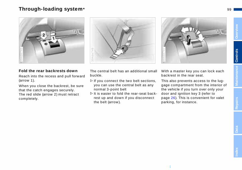
99n
Over
view
Cont
rols
Mai
nten
ance
h a master key you can lock each krest in the rear seat.
also prevents access to the lug-e compartment from the interior of
Through-loading system*
Fold the rear backrests downReach into the recess and pull forward (arrow 1).
When you close the backrest, be sure
394d
e745
The central belt has an additional smallbuckle.
> If you connect the two belt sections, you can use the central belt as any
394d
e746
Repa
irs
Data
Inde
x
vehicle if you turn over only your r and ignition key 3 (refer to e 26). This is convenient for valet king, for instance.
that the catch engages securely. The red slide (arrow 2) must retract completely.
normal 3-point belt> It is easier to fold the rear-seat back-
rest up and down if you disconnect the belt (arrow).
Witbac
Thisgag
394d
e747
the doopagpar

100nSki bag*
lling the center armrest the armrest into position from , then apply pressure until you t snap into position.
Be sure that the seat covers are not damaged by the side pins.<
InstaGuideabovehear i
The ski bag allows the safe and clean transport of up to four pairs of standard skis or up to two snowboards.
The length of the ski bag and the addi-tional space provided in the luggage compartment make it possible to carry skis with a length of up to 6.8 ft (2.10 meters). Because of the tapered shape of the bag, the ski bag can only accommodate two pairs of skis with a length of 6.8 ft (2.10 meters).
Removing the center armrest (Not for vehicles with the through-loading system, refer to page 102).
394d
e748
1. Fold the center armrest completely outward
2. Loosen the trim from the upper Velcro® fastener and place it on the armrest
3. Grasp the front of the armrest with one hand, then use your other hand to reach down behind the armrest and pull up sharply (arrow).

101n
Over
view
Cont
rols
Mai
nten
ance
Ski bag*
uring the loadSecure the bag's contents by tightening down the retaining
p at the buckle.<
ch ce he
Sec
stra
530d
e284
Repa
irs
Data
Inde
x
se be sure that the skis are clean re loading them into the bag. Be ful to avoid damage from sharp es.
ve
d .<
Pleabefocareedg
Loading1. Press the release button (arrow 1):
the cover panel in the luggage com-partment is unlocked
394d
e749
4. Use the magnetic retainers to attathe cover panel to the upper surfa(metal surface below rear tray) of tluggage compartment.
394d
e750
2. Press the detent levers (arrows 2) inward and fold the cover to the front
3. Extend the ski bag between the front seats. The zipper provides conve-nient access to stored items. It may be opened to allow the ski bag to dry
To store the ski bag, perform the abosteps in reverse sequence.
An unsecured ski bag could leato loss of vehicle control and in
case of an accident to personal injury

102nSki bag* Cargo loading
ring the load ure smaller, light pieces with the age net or use retaining straps*
er to page 34)
Secu>Sec
lugg(ref
39m
de0
37
large, heavy pieces, see your W center for load-securing ices*. The lashing eyes provided he corners of the luggage com-tment serve for mounting these -securing devicesply with the information
losed with the load-securing ices.
-
>ForBMdevat tparload
>Comencdev
With through-loading system1. Fold the center armrest outward.
Loosen the trim from the upper Velcro® fastener and place it on the
394d
e751
Stowing cargo When transporting cargo in your BMW:
>Load heavy cargo as far forward as
39m
de0
36
armrest2. Press button 1 downward and swing
the cover forward3. Press knob 2: the cover in the lug-
gage compartment is unlocked.
possible – directly behind the back-rests or the luggage compartment partition – and as low as possible
>Cover sharp edges and corners>Do not pile objects higher than the
top edge of the backrest> If you are transporting very heavy
loads when the rear seat is not occupied, secure the outer safety belts inthe opposite buckles.

103n
Over
view
Cont
rols
Mai
nten
ance
Cargo loading Roof-mounted luggage rack*
hould therefore always remember exceed the approved roof load ity, the approved gross vehicle t or the axle weights when g the rack. These weights are
under "Technical Data", 142.
sure that the load is not too bulky, ttempt to distribute it evenly. s load the heaviest pieces first (on ttom). Be sure that adequate nce is maintained for raising the /tilt sunroof.
Secure the roof luggage correctly and securely to prevent it from
You snot tocapacweighloadinlistedpage
Makeand aAlwaythe boclearasliding
Repa
irs
Data
Inde
x
g or being lost during driving er to following traffic).<
smoothly and avoid sudden eration and braking. Do not corner h speeds.
shiftin(dang
Drive accelat hig
Always position and secure the load correctly. If you do not, it can
endanger the passengers during braking or evasive maneuvers.Never exceed either the approved gross vehicle weight or the approved loads for either of the axles (refer to page 142), as overloading the vehicle beyond the legally approved levels can severely compromise its operating safety.Do not carry hard or heavy objects unsecured in the passenger compart-ment. If you do so, they may be pro-jected through the air during braking and evasive maneuvers, thus endan-
A special roof-rack system is available as an optional extra for your BMW. Please observe the precautions included with the installation instruc-
394d
e757
gering vehicle occupants.< tions.
AnchoragesAccess to the anchorages:To fold up the cover (arrow), please usethe tool provided with the roof-rack system.
Loading and driving notesRoof-mounted luggage racks raise the center of gravity of the vehicle when they are loaded. For this reason, they have a major effect on the vehicle's handling and steering response.

104n
105n
Over
view
Cont
rols
aint
enan
ce
Overview
Controls and features
Operation, maintenance
MRe
pair
sDa
tade
x
Owner service procedures
Index
Technical data
In
Mainte-

106n
e systemximately 300 miles (500 km) must
e before the brake pads and achieve the optimal pad-surface ear patterns required for trouble-peration and long service life later
ak-in the separate parking brake , apply the parking brake lightly
coasting to a standstill (at a traffic l, for instance), provided that conditions allow you to do so. To corrosion, repeat this procedure ime to time.
The brake lamps do not come on
Break-in procedures
To ensure that your vehicle provides maximum economy throughout a long service life, we request that you observe the following.
Your BMW M5 is a masterpiece of superlative technology. To ensure
that you derive maximum satisfaction from its extensive array of advanced features while simultaneously creating the basis for many years of driving plea-sure, we urge you to observe the fol-lowing precautions during the initial period of operation.<
Engine and differential
TiresOwing to technical factors associated with their manufacture, tires do not achieve their full traction potential until an initial break-in period has elapsed. Thus drive with extra care during the initial 200 miles (300 km).
Comply with all official speed limits.
When the vehicle is operated on wet or slushy roads, a wedge of
water may from between the tire and the road surface. This phenomenon is referred to as aquaplaning, or hydro-planing, and can lead to partial or com-plete loss of traction, vehicle control
when the parking brake is applied. m for the brake system servo unit
ur BMW is available only when the e is running. When you move the le with the engine shut off – when g, for instance – substantially r levels of pedal force will be ed to brake the vehicle.<
hlutch will also begin to function ally after about 300 miles m). Engage the gears carefully the break-in period.
Up to 1,200 miles (2,000 km):Drive at varying engine speeds and road speeds, but do not exceed 5,500 rpm or 105 mph (170 km/h) during this period.
Comply with all official speed limits.
Do not depress the accelerator pedal to the full-throttle position.
Following the Break-in inspection at 1,200 miles (2,000 km), you can gradu-ally increase engine or road speeds.
You should also comply with these break-in procedures if the engine or dif-ferential is replaced later in the course of the vehicle service life.
and braking effectiveness. Reduce your speed on wet roads.<
BrakApproelapsrotorsand wfree oon.
To bredrumswhensignatrafficavoidfrom t
Vacuuon yoenginvehictowinhigherequir
ClutcThe coptim(500 kduring

107n
Over
view
Cont
rols
Mai
nten
ance
Driving notes Antilock Brake System
concept Antilock Brake System (ABS) keeps wheels from locking during braking, eby enhancing active driving safety.
h ABS, the shortest possible braking ances are achieved under most ditions (on straight-aways and in es, on asphalt, ice, wet road sur-s, etc.).
king with ABSu are in a situation that requires
braking, you will exploit the full ben- of the ABS system if you apply imum pedal pressure ("panic stop").
ation at the brake pedal combined
n
ct
e, ng rs,
TheThethe ther
Witdistconcurvface
BraIf yofull efitsmax
Puls
Repa
irs
Data
Inde
x
sounds from the hydraulic circuits cates to the driver that ABS is in its ve mode.
withindiacti
Brakes:Do not rest your foot on the brake
pedal while driving. Even light but con-sistent pedal pressure can lead to high temperatures, brake wear and possibly even brake failure.Hydroplaning:When driving on wet or slushy roads, reduce vehicle speed. If you do not, a wedge of water may form between the tires and the road surface. This phe-nomenon is referred to as aquaplaning, or hydroplaning, and can lead to partial or complete loss of traction, vehicle control and braking effectiveness.Driving through water: When there is water on the roads, do
Rear parcel tray:Do not place heavy or hard objects othe rear parcel tray. If you do so, theycould pose a danger to vehicle occu-pants during a braking or evasive maneuver.Clothes hooks:When suspending clothing from the hooks, ensure that they will not obstruthe driver's vision. Do not hang any heavy objects on the hooks, otherwispassengers could be injured e.g. duriany hard braking or evasive maneuveor during an accident.<
not drive in it if it is deeper than 1 ft (30 cm). If the water is at that depth, drive only at walking speed, otherwise the vehicle can sustain damage to the engine, the electrical systems and the transmission.

108nBrake system
descending steep hills and ded grades, downshift to a gear ill allow you to continue safely nly a minimal amount of braking. nimizing the loads placed on the system, this strategy helps e that optimal brake system nse will remain available at all .
Do not coast with the clutch depressed or with the transmis-r gearshift lever in Neutral. Do not with the engine shut off. The e provides no braking effect when utch is depressed and there is no
-
Whenextenthat wwith oBy mibrakeensurrespotimes
sion ocoastenginthe cl
r-assist for braking or steering the engine is not running. allow floor mats, carpets or any objects to protrude into the area d the accelerator, clutch and pedals and obstruct their move-<
e padsFor your own safety: use only brake pads that BMW has ved for your particular vehicle l. BMW cannot evaluate non-ved brake pads to determine if re suited for use, and therefore t ensure the operating safety of hicle if they are installed.<
powewhenNeverother arounbrakement.
Brak
appromodeapprothey acannothe ve
Brake fluid level If the brake fluid level is too low and brake pedal travel has become notice-ably longer, there may be a defect in one of the two brake system's hydraulic circuits.
Proceed to the nearest BMW center. Higher brake application
pressure may be necessary under these conditions, and the vehicle may exhibit a slight tendency to pull to one side when the brakes are applied. Braking distances may also be longer. Please remember to adapt your driving style accordingly.<
Disc brakesLimited vehicle use, extended periods with the vehicle parked or in storage, and operating conditions in which braking is restricted to gentle, low-pressure applications will all increase the tendency for corrosion to form on the rotors; this is often accompanied by a simultaneous accumulation of contamination on the brake pads. The padsmust exert a certain minimal level of pressure against the rotors for the discbrakes' inherent self-cleaning effect to remain effective; the pressure availableunder the above conditions may not provide adequate cleansing.
If the brake rotors are corroded, they will tend to respond to braking with a pulsating effect that even extended brake applications will fail to cure.
When driving in heavy rain and on wet roads it is a good idea to apply light pressure to the brake pedal every few miles. Monitor traffic conditions to ensure that this maneuver does not pose a hazard to you or to other road users. The heat generated in this pro-cess helps dry the pads and rotors to ensure that your brake system will respond with undiminished efficiency when you need it.

109n
Over
view
Cont
rols
Mai
nten
ance
mm) these indicators, signal that tires have reached the legally per-sible wear limit.
Do not drive on a deflated (flat) tire. A flat tire greatly impairs steering
braking response, and can lead to plete loss of control over the
icle. id overloading the vehicle so that permitted load on the tires is not eeded. Overloading leads to over-ting and causes damage inside the . The ultimate result can assume the of a sudden air loss.sual vibrations encountered during
mal vehicle operation can indicate a
Tire inflation pressure Tire condition
Information for your safetyThe factory-approved radial tires are matched to the vehicle and have been selected to provide optimum safety and driving comfort on your vehicle.
It is not merely the tire's service life, but also driving comfort and – above all else – driving safety that depend on the condition of the tires and the main-tenance of the specified tire inflation pressure.
Incorrect inflation pressures are a frequent cause of tire problems
and flat tires. Tire pressure also has a major effect on your BMW's handling
Tire tread – tire damageInspect your tires frequently for tread wear, signs of damage and for foreign objects lodged in the tread. Check the
390d
e331
Repa
irs
Data
Inde
x
tire or some other vehicle malfunc-. The type of problem can be caused ontact with curbs, etc. This is also for irregularities in the vehicle's dling characteristics, such as a pro-nced tendency to pull to the left or t. Should this occur, respond by ediately reducing your speed. Pro-d carefully to the nearest BMW ter or professional tire center, or e the vehicle towed in to have it, its els and tires inspected. damage (up to and including blow-) can endanger the lives of both the
icle occupants and other road rs.<
response. Check tire inflation pressures on a regular basis (refer to page 22), at least every two weeks and before every long trip. If you fail to observe these precautions, incorrect tire pressures can cause driving instability and tire damage, ultimately resulting in an accident.<
tread depth.
The tread depth should not drop below 0.12 in (3 mm), even though, for example the legally specified minimumtread depth in Europe is only 0.063 in (1.6 mm). Below a tread depth of 0.12 in (3 mm) there is an increased riskof hydroplaning, even at relatively moderate speeds and with only small amounts of water on the road.
Tread wear indicators, refer to arrow, are embedded around the tire circum-ference in the base of the tire tread. Their locations are indicated on the tiresidewall with TWI – Tread Wear Indi-cator. At a tread depth of 0.063 in
(1.6the mis
andcomvehAvothe excheatiresformUnunor
-
flat tionby ctruehannourighimmceecenhavwheTireoutsvehuse

110nTire replacement
Car Safety Standard No. 109. s B and A represent higher levels formance on the laboratory test l than the minimum required by
The temperature grade for this tire is established for a tire that is rly inflated and not overloaded. sive speed, underinflation, or sive loading, either separately or bination, can cause heat buildup
ossible tire failure.<
rm Tire Quality Gradingy grades can be found where
MotorGradeof perwheelaw.
propeExcesexcesin comand p
UnifoQualit
able on the tire sidewall between shoulder and maximum section . For example:
wear 200 on AA erature A
-
applictread width
TreadTractiTemp
To maintain good handling and vehicle response, use only tires of a single tread configuration from a single manu-facturer. BMW tests wheel and tire combinations and approves them.
DOT Quality GradesTreadwearTraction AA A B CTemperature A B C
All passenger car tires must con-form to Federal Safety Require-
ments in addition to these grades.<
Treadwear
TractionThe traction grades, from highest to lowest, are AA, A, B and C. Those grades represent the tire's abilityto stop on wet pavement as measured under controlled conditions on speci-fied government test surfaces of asphalt and concrete. A tire marked C may have poor traction performance.
The traction grade assigned to this tire is based on straight-
ahead braking traction tests, and does not include acceleration, cornering, hydroplaning, or peak traction charac-teristics.<
The treadwear grade is a comparative rating based on the wear rate of the tire when tested under controlled condi-tions on a specified government test course.For example, a tire graded 150 would wear one and one-half (1g) times as well on the government course as a tire graded 100. The relative performance of tires depends upon the actual condi-tions of their use, however, and may depart significantly from the norm due to variations in driving habits, service practices and differences in road char-acteristics and climate.
TemperatureThe temperature grades are A (the highest), B and C, representing the tire's resistance to the generation of heat and its ability to dissipate heat when tested under controlled condi-tions on a specified indoor laboratory test wheel. Sustained high temperature can causethe material of the tire to degenerate and reduce tire life, and excessive temperature can lead to a sudden flat tire. The grade C corresponds to a level of performance which all passenger car tires must meet under the Federal
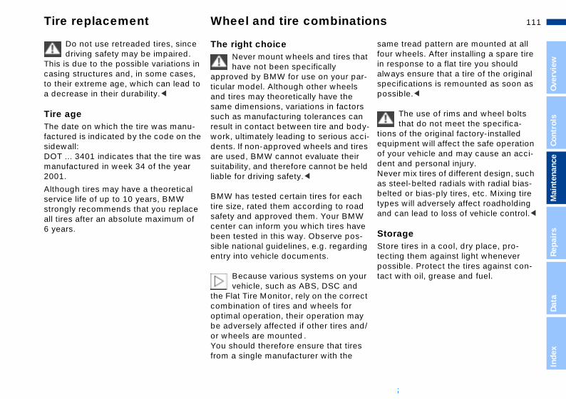
111n
Over
view
Cont
rols
Mai
nten
ance
Tire replacement Wheel and tire combinations
e tread pattern are mounted at all wheels. After installing a spare tire sponse to a flat tire you should
ays ensure that a tire of the original cifications is remounted as soon as sible.<
The use of rims and wheel bolts that do not meet the specifica-
s of the original factory-installed ipment will affect the safe operation our vehicle and may cause an acci-t and personal injury.er mix tires of different design, such teel-belted radials with radial bias-ed or bias-ply tires, etc. Mixing tire s will adversely affect roadholding
at
r-
s n y-ci-es ld
h d
samfourin realwspepos
tionequof ydenNevas sbelttype
Repa
irs
Data
Inde
x
can lead to loss of vehicle control.<
ragere tires in a cool, dry place, pro-ing them against light whenever sible. Protect the tires against con- with oil, grease and fuel.
e -ng
ur ct
y d/
s
and
StoStotectpostact
Do not use retreaded tires, since driving safety may be impaired.
This is due to the possible variations in casing structures and, in some cases, to their extreme age, which can lead to a decrease in their durability.<
Tire ageThe date on which the tire was manu-factured is indicated by the code on the sidewall:DOT ... 3401 indicates that the tire was manufactured in week 34 of the year 2001.
Although tires may have a theoretical service life of up to 10 years, BMW
The right choice Never mount wheels and tires thhave not been specifically
approved by BMW for use on your paticular model. Although other wheelsand tires may theoretically have the same dimensions, variations in factorsuch as manufacturing tolerances caresult in contact between tire and bodwork, ultimately leading to serious acdents. If non-approved wheels and tirare used, BMW cannot evaluate theirsuitability, and therefore cannot be heliable for driving safety.<
BMW has tested certain tires for eactire size, rated them according to roa
strongly recommends that you replaceall tires after an absolute maximum of 6 years.
safety and approved them. Your BMWcenter can inform you which tires havbeen tested in this way. Observe possible national guidelines, e.g. regardientry into vehicle documents.
Because various systems on yovehicle, such as ABS, DSC and
the Flat Tire Monitor, rely on the correcombination of tires and wheels for optimal operation, their operation mabe adversely affected if other tires anor wheels are mounted.You should therefore ensure that tirefrom a single manufacturer with the

112nSpecial characteristics of winter tires Snow chains*
se of BMW narrow-link snow s on winter tires is approved only rs and only on the rear wheels. ly with all manufacturer's safety utions when mounting the chains. t exceed a speed of 30 mph /h) while driving with mounted
chains.
It is not possible to mount snow chains with 18-inch wheels and
.
The uchainin paiCompprecaDo no(50 kmsnow
tires.<
Choosing the right tireBMW recommends winter tires (M+S radial tires) for driving in adverse winter road conditions. While "all-season" tires (M+S designation) provide better winter traction than summer tires with the load ratings H, V, W, Y and ZR, they generally do not achieve the perfor-mance of winter tires. In the interests of safe tracking and steering response, install radial tires made by the same manufacturer and with the same tread configuration on all four wheels if you elect to mount winter tires.
Tire condition, tire inflation pressureWhen the tread wears to a depth of lessthan 0.16 in (4 mm) there is a substan-tial reduction in the tire's ability to pro-vide adequate traction under winter driving conditions. To ensure continuedsafety, tires with this amount of tread wear should always be replaced.
Comply with the specified tire inflation pressures – and be sure to have the wheel and tire assemblies balanced every time you change the wheels/tires
Never exceed the maximum speed approved for your specific winter
tires.Unprofessional attempts by laymen to service tires can lead to damage and accidents.Have this work performed by skilled professionals only. Any BMW center has the required technical knowledge and the proper equipment and will be happy to assist you.<

113n
Over
view
Cont
rols
Mai
nten
ance
closew the hood to fall from a height of ut 4 in (10 cm) so that it audibly ages.
Hood
To unlockPull the lever located under the left-hand side of the instrument panel.
390d
e759
To openPull the release handle and open the hood.
390d
e760
Repa
irs
Data
Inde
x
To avoid injuries, be sure that the travel path of the hood is clear
n it is closed, observing the same cautions recommended for all ing procedures.u notice that the hood is not com-ely closed while driving, stop imme-ely and close it securely.<
Do not attempt to service your vehicle if you do not have the
required technical background. Failure to work in an informed, professional manner when servicing components and materials constitutes a safety hazard for vehicle occupants and other road users. If you are not familiar with the guidelines, please have the opera-tions performed by your BMW center.<
To Alloaboeng
390d
e761
whepreclosIf yopletdiat

114nEngine compartment essentials
id (under rofilter) 118
mp
3 Engine oil dipstick 115
4 Engine oil filler neck 116
5 Coolant expansion tank 118
ervoir for the intensive-cleaning tem 115
ervoir for the windshield and dlamp washer system 115
6 Ressys
7 Reshea
1 Reservoir for brake fluthe housing of the mic
2 Auxiliary terminal for justarting 133
39m
de1
50

115n
Over
view
Cont
rols
Mai
nten
ance
Washer fluids Engine oil
ecking oil level ark the vehicle on a level surfacellow the engine to run at operating mperature for at least 15 seconds
Ch1. P2. A
te
39m
de0
42
Repa
irs
Data
Inde
x
t idle, then shut it offfter approx. one minute, pull the ipstick out and wipe it off with a lean lint-free cloth, paper towel, or imilar materialarefully push the dipstick all the ay into the guide tube and pull it ut againhe oil level should be between the o marks on the dipstick.
ith fuel economy, oil consumption irectly influenced by your driving e and vehicle operating conditions.
id. 7 r
le.
in o
.
a3. A
dcs
4. Cwo
5. Ttw
As wis dstyl
Headlamp and windshield washer systemCapacity in US quarts (liters).Windshield washer:
39m
de1
28
Intensive-cleaning washer reservoirCapacity approx. 1.1 US quarts (1.0 liter).
39m
de1
29
Approx. 3.7 US quarts (3.5 liters)With headlamp-washing system:Approx. 6.3 US quarts (6.0 liters).
Fill with water and – if required – with a washer antifreeze (according to manu-facturer's recommendations).
We recommend that you mix the washer fluid before adding it to
the reservoir.<
Fill with intensive-cleaning washer fluIt resists freezing down to approx. –17 (–27 6) and is available from youBMW center.
Antifreeze agents or intensive-action washer fluids for the
washer systems are highly inflammabFor this reason, keep them away fromsources of flame and store them onlytheir original containers. Store them sthat they are inaccessible to childrenComply with the instructions on the containers.<

116nEngine oil
Continuous exposure to used oil has caused cancer in laboratory g.is reason, any skin areas that into contact with oil should be ghly washed with soap and
. oil, grease, etc., out of reach of en. Comply with warning labels formation on containers.<
Comply with the applicable envi-ronmental laws regulating the dis- of used oil.<
testinFor thcomethorouwaterStorechildrand in
posal
The oil volume between the two marks on the dipstick corresponds to approx. 1.1 US quarts (1 liter). Do not fill beyond the upper mark on the dipstick. Excess460d
e189
To add oil While you should wait until the level hasdropped to just above the lower marksbefore adding oil, you should never
39m
de1
10
oil will damage the engine. allow the oil level to fall below this mark.
BMW engines are designed to operate without oil additives; the
use of additives could lead to damage in some cases. This is also true for the manual transmission, the differential, and the power steering system.<
Recommendation: have the oil changedby your BMW center only.

117n
Over
view
Cont
rols
Mai
nten
ance
Engine oil Coolant
Do not add coolant to the cooling system when the engine is hot.
u attempt to do so, escaping lant can cause scalds. To avoid the sibility of secondary damage, never anything other than factory-roved, nitrite and amino-free nded-duty antifreeze with corrosion
bitor. Your BMW center is familiar these specifications.
ifreeze and anti-corrosion agents hazardous to health. You should ays store them in their original con-ers and in a location which is out of h of children. For this reason, do spill antifreeze with corrosion inhib-on hot engine parts. It could ignite
b-
s
ur
s
all
If yocooposuseappexteinhiwithAntare alwtainreacnot itor
Repa
irs
Data
Inde
x
cause burns.<
andSpecified engine oils The quality of the engine oil is extremely important for the function and service life of an engine. Based on extensive testing, BMW approves only certain grades of engine oil.
Use only approved "BMW High Perfor-mance Synthetic Oil."
If you are unable to obtain "BMW High Performance Synthetic Oil," you can add small amounts of synthetic oil in between oil changes. Only use oils with the API SH specification or higher.
Ask your BMW center for details concerning the specific "BMW
Viscosity ratings Viscosity is the oil flow rating as estalished in SAE classes.
The selection of the correct SAE clasdepends on the climatic conditions inthe area where you typically drive yoBMW.
Approved oils are in SAE classe5W-40 and 5W-30.<
These oils may be used for driving in ambient temperatures.
High Performance Synthetic Oil" or "special oils" which have been approved.<
You can also call BMW of North America at 1-800-831-1117 or visit this website: www.bmwusa.com to obtain this information.

118nCoolant Brake fluid
Brake fluid is hygroscopic, that is, it absorbs moisture from the air ime.er to ensure the safety and reli- of the brake system, have the fluid changed every two years at
center. Refer also to the Service arranty Information Booklet (US
ls) or the Warranty and Service Booklet (Canadian models). fluid is hazardous to health and ges the vehicle's paint. You d always store it in its original iner and in a location which is out ch of children. Do not spill the nd do not fill the brake fluid reser-
over tIn ordabilitybrakea BMWand WmodeGuideBrakedamashoulcontaof reafluid a
eyond the MAX mark. The brake ould ignite upon contact with hot e parts and cause serious burns.<
Comply with the applicable envi-ronmental laws regulating the dis- of brake fluid.<
voir bfluid cengin
posal
Checking coolant level and adding coolantCorrect coolant level when the engine is cold (approx. 68 7/20 6):
39m
de1
11
Brake fluid levelThe warning lamp for the brakesystem hydraulic circuits comeson and/or the message "CHECKBRAKE FLUID" appears in the Check Control: Brake fluid level too low.
To add brake fluidThe brake fluid reservoir is located under the microfilter housing on the driver's side of the vehicle. For adding brake fluid or for determining and cor-recting the cause of brake fluid loss, consult your BMW center. Your BMW center is familiar with the specifications
In the translucent container's visible range, as far as the graduation marked KALT/COLD.
1. Turn the cap counterclockwise slightly in order to allow accumulated pressure to escape
2. If the coolant is low, slowly add coolant until the correct level is reached – do not overfill.
Comply with the applicable envi-ronmental laws regulating the dis-
posal of extended-duty antifreeze with corrosion inhibitor.<
for factory-approved brake fluids (DOT 4).
Brake fluid loss may result in extendedbrake pedal travel. If this occurs, refer to the information on page 108.

119n
Over
view
Cont
rols
Mai
nten
ance
ce and Warranty Information let (US models)/Warranty ervice Guide Booklet
adian models)ditional information on mainte- intervals and procedures, please o the Service and Warranty Infor-n Booklet (US models) or the War-and Service Guide Booklet (Cana-odels).
recaution against corrosion, it is ble to have the body checked for
ge from rocks or gravel at the time, depending upon operating tions.
The BMW Maintenance System
The BMW Maintenance System has been designed as a reliable means of providing maximum driving and oper-ating safety – and as cost-effectively as
380us0
08
Service Interval DisplayConventional systems rely solely on distance traveled to determine when service is due. The BMW Maintenance System, on the other hand, began many years ago to take the actual conditions under which the vehicle is driven into consideration. After all, different drivers can accumulate mileage in very dif-ferent ways.
From a maintenance point of view, 62,000 miles (100,000 km) of short-dis-tance driving cannot be compared with 62,000 miles (100,000 km) of long-dis-tance highway travel.
Repa
irs
Data
Inde
x
Have your vehicle's maintenance and repairs performed at your center.re that all maintenance work is med in the Service and Warranty ation Booklet (US models) or the nty and Service Guide Booklet dian models). These entries are roof that the vehicle has received r maintenance. They are also a ement for warranty claims.<
possible for you.
Please keep in mind that regular main-tenance is not only necessary for the safety of your vehicle, but also plays a significant role in maintaining its resale value.
In response to this fact, the BMW Main-tenance System monitors operating conditions as the basis for determining the optimum service intervals for your individual vehicle. The BMW Mainte-nance System includes the Engine Oil Service and Inspections I and II.
Determining the maintenance intervals according to the actual loads on the vehicle covers every kind of operating situation. However, even those who drive only short distances – significantly less than 6,000 miles (10,000 km) annu-ally – should have the engine oil changed at least every 2 years since oil deteriorates over time, regardless of use.
ServiBookand S(CanFor adnancerefer tmatioranty dian m
As a padvisadamasamecondi
BMWBe suconfirInformWarra(Canayour p
regularequir
120nTechnical modifications California Proposition 65 Warning
-
t
Light-emitting diodes (LEDs)Light-emitting diodes installed behind translucent lenses serve as the light source for many of the controls and dis-plays in your vehicle. The concept behind their operation is related to that employed for lasers.
Do not remove the protective lens and avoid staring directly at the
unfiltered beam for extended periods (several hours), as inflammation of the iris could result.<
California laws require us to state the following warning:
Engine exhaust, some of its con-stituents, and certain vehicle com
ponents contain or emit chemicals known to the State of California to cause cancer and birth defects and reproductive harm. In addition, certain fluids contained in vehicles and certainproducts of component wear contain oremit chemicals known to the State of California to cause cancer and birth defects or other reproductive harm.Battery posts, terminals and related accessories contain lead and lead
compounds. Wash your hands after handling. Used engine oil contains chemicals thahave caused cancer in laboratory ani-mals. Always protect your skin by washing thoroughly with soap and water.<
121n
Over
view
Cont
rols
Mai
nten
ance
OBD interface socket
When the fuel filler cap is not properly tightened, the OBD
tem can detect the vapor leak and indicator will light up. If the filler cap ubsequently tightened, the indi-r should go out within a few days.<
s ot e.
r er
d
systhe is scato
Repa
irs
Data
Inde
x
The Onboard Diagnostic (OBD) inter-face socket is located on the left of the driver's side at the bottom of the instru-ment panel and under a cover. The cover has the letters "OBD" on it.
390us7
39
An illuminated indicator informyou of the need for service, nof the need to stop the vehicl
However, the systems should be checked by your BMW center at the earliest possible opportunity.
Under certain conditions, the indicatowill blink or flash. This indicates a rathsevere level of engine misfire. When this occurs, you should reduce the speed and consult the nearest BMWcenter as soon as possible. Severe engine misfire over only a short perioof time can seriously damage emis-sions-control components, especiallythe catalytic converter.
The purpose of the OBD (Onboard-Diagnostics) system is to assure proper emission-control system operation for the vehicle's lifetime by monitoring emissions-related components and systems to detect deterioration and malfunction.
Service Engine Soon warninglamp for Canadian models.

122n

123n
Over
view
Cont
rols
Mai
nten
ance
Repa
irs
Data
dex
Overview
Controls and features
Operation, maintenance
Owner service procedures
Index
Technical data
In
Repairs

124n
mps and bulbs are essential fac-ontributing to the safety of your le. Therefore, comply fully with the ing instructions during bulb ement. If you are not familiar with
f the procedures, consult your center.
Do not touch the glass portion of a new bulb with your bare hands even small amounts of impurities n to the surface and reduce the e life of the bulb. Use a clean paper napkin, or a similar mate-r hold the bulb by its metallic <
Onboard tool kit Windshield wiper blades Lamps and bulbs
The onboard tool kit is located in the luggage compartment lid.
Loosen the wingnut to open.
394d
e080
1. Lift the wiper arm up slightly and hold it firmly
2. Press back the release (arrow) and pull the wiper blade back toward the
390d
e766
acement bulb set is available from MW center.
Always switch off all electrical accessories and systems before ng on them. As an alternative, you lso disconnect the cable from the y's negative terminal. Failure to ve this precaution can lead to circuits. vent injuries and damage,
ly with any instructions provided bulb manufacturer.<
base of the wiper arm3. Install the new blade and slide the
release back into position.
Use only wiper blades approved by BMW.<
The lators cvehicfollowreplacany oBMW
sinceburn iserviccloth,rial, obase.
A replyour B
workican abatterobsershort To precompby the

125n
Over
view
Cont
rols
Mai
nten
ance
Lamps and bulbs
n signal indicators/parking ps (side marker lamps), front l-filament bulb, 21 watt
urn the bulb holder to the left and
aTurlamDua
1. T
390d
e670
Repa
irs
Data
Inde
x
emoveemove and replace the bulb.
d
r
r2. R
Xenon lamps The service life of these bulbs is very long and the probability of a failure is very low, provided that they are not switched on and off an unusual number of times. If one of these bulbs should nevertheless fail, it is possible to con-tinue driving with great caution using the fog lamps, provided traffic laws in your area do not prohibit this.
Never attempt to perform bulb changes or any other service oper-
ations on the xenon lamps. Always have them serviced by professional techni-cians. The extremely high voltages at which these lamps operate constitute a
Standing lamps10 watt bulb
The bulb holder and reflector are
390d
e669
potentially lethal safety hazard.<
When cleaning the headlamps, please observe the following:
>Do not clean by wiping with a dry cloth (this causes scratches). Never use abrasives or strong solvents to clean the covers
>Remove dirt and contamination (such as insects) by soaking with BMW Car Shampoo and then rinsing with ample water
>Always use a deicer spray to remove accumulated ice and snow – never use a scraper.<
single unit and are both changeat the same time.<
1. Turn the bulb holder with reflectorto the left (arrow) and remove
2. Disconnect the plug3. Plug the new bulb holder into the
plug connector. Be sure that it is securely engaged
4. Insert the reflector with bulb holdeand turn to the right as far as possible.

126nLamps and bulbs
amps lamp/side marker lamps: emitting diodesining bulbs: 21 watt
Tail lRear Light-Rema
394us7
21
n signal indicator white
r lamp/side marker lamps red
kup lamps white
ke lamps red
lector red
Please contact your BMW center if there is a defect in the rear side marker lamp assembly.<
-
-
1 Tur
2 Rea
3 Bac
4 Bra
5 Ref
lamp/
Side turn signal indicators5 watt bulb
1. Use finger pressure against the rear
390d
e768
Front fog lamps HB4, 51 watt bulb
The bulb is pressurized. There-39m
de1
04
end of the lens (arrow) to press it for-ward for removal
2. Apply gentle pressure to the bulb while turning it to the left to remove.
fore, wear safety glasses and protective gloves. Failure to observe theseprecautions can result in physical injuryif the bulb breaks.<
1. Pull the cover panel next to the headlamp forward to remove
2. Loosen the screw, refer to arrow, and swing the lamp assembly out
3. Release the spring on the back of thelamp and turn the cover to the left
4. Release the clamp, remove the contact base and replace the bulb.

127n
Over
view
Cont
rols
Mai
nten
ance
Lamps and bulbs
ense plate lamps att bulb
sert a screwdriver into the slot nd press to the left (arrow); this dis-
er
Lic5 w
1. Ina
394d
e772
Repa
irs
Data
Inde
x
dges the lampemove the lamp and replace the ulb.
e.
lo2. R
b
1. Use the upper handle to fold down the side panel in the luggage com-partment
2. Turn the corresponding bulb holder to the left (arrow) and remove it
394d
e769
Center (high-mount) brake lamp21 watt bulb
1. Open the luggage compartment lid2. Use a screwdriver to unclip the cov
394d
e123
3. Press the defective bulb gently and turn it to the left. Remove the bulb and replace it
4. Insert the bulb holder and turn to the right as far as possible.
panel (on the underside of the storage tray) (arrow)
3. Turn the bulb holder to the left andremove
4. Apply gentle pressure to the bulb while turning it to the left to remov

128nRepairing a flat tire
is part of the M Mobility mOff switch
This syste1 On/
39m
de1
06
nection hose with pressure ge for connecting the compressor the sealant container or to con-t the compressor to the wheel
ssure gauge for indicating the tire ssure
nector hose from the sealant tainer to the wheel
rning sticker for maximum speed
g and cable for the cigarette ter socket
tective gloves (not illustrated)
2 Congauwithnec
3 Prepre
4 Concon
5 Wa
6 Pluligh
7 Pro
Precautions in case of a flat tire: Stop the vehicle as far as possible
from passing traffic. Switch on the hazard warning flashers.Turn the steering wheel to the straight-ahead position, remove the key and engage the steering lock. Shift into 1st or reverse and engage the parking brake.All passengers should be outside the vehicle and well away from your imme-diate working area (behind a guardrail, for instance).If necessary, set up your warning tri-angle or portable hazard warning lamp on the roadside at an appropriate dis-
The M Mobility system is located in theluggage compartment under the floor mat:
1. Lift up the floor mat and then raise 39m
de1
32
tance from the rear of the vehicle. Comply with all safety guidelines and regulations.<
M Mobility systemFor repairing a flat tire, you will find an M Mobility system in the BMW M5. With the aid of this system, you can apply a liquid sealant to the inside of the tire, thereby sealing off the damaged area, and then continue driving.
The M Mobility system makes the trans-port of a spare wheel superfluous and minimizes the curb weight.
the front cover panel2. Loosen the M Mobility system from
its storage location.
Please note that the system's sealant container must be
replaced every three years by your BMW center if the device is not used.<

129n
Over
view
Cont
rols
Mai
nten
ance
Repairing a flat tire
lip open the cover and pull out the nclosed protective gloves. Take out ose 2 with the pressure gauge and crew it to the connection on the ealant container, as shown in the
ct p
id
3. Fehss
39m
de1
43
Repa
irs
Data
Inde
x
lustrationake sure that the system has been
witched off (position 0). Take out lug 6 and plug it into the cigarette ghter socket in the passenger com-artment (refer to page 98)
il4. M
splip
Use the M Mobility systemIf possible, leave the foreign object in the tire.<
Do not exceed the maximum speeds indicated below, as an
accident could result.Before you use the M Mobility system, read the warnings and danger notices on the device carefully.<
1. Remove the warning sticker 5 for maximum speed that is located on top of the device and affix it to the steering wheel
2. Take off the round cover and extrahose 4. Unscrew the valve stem cafrom the defective tire, then screwthe hose onto the valve stem. Avolosing the valve stem cap
39m
de1
42

130nRepairing a flat tire
ke out the hose with the pressure uge and screw it onto the valve.ke out the plug and plug it into e cigarette lighter socket in the
t t
8. TagaTath
39m
de1
45
ssenger compartmenteset the tire pressure to 29 psi 00 kilopascal), and:Increase the tire pressure: turn on the M Mobility system (position I). To check the new tire pressure briefly turn off the deviceReducing tire pressure: turn the screw on the back of the pressure gauge, a valve located there will open
pa9. R
(2>
>
5. Make sure that the screw on the rear of the pressure gauge 3 is tightened down. Turn on the M Mobility system (position I, refer to illustration) and
39m
de1
44
7. Right afterward, drive at least 1.2 miles (2 km), so that the liquid sealant distributes evenly throughouthe inside of the tire. If possible driveat no less than 15 mph (20 km/h), bunot more than 40 mph (60 km/h).Stop in a suitable spot
allow 3 minutes to elapse, to let the sealant flow in. At this point, it is insignificant what the tire pressure is
6. Turn the device off.Disconnect the connector hose from the sealant container and the wheel valve. Stow the M Mobility system in the luggage compartment

131n
Over
view
Cont
rols
Mai
nten
ance
Repairing a flat tire Battery
Battery posts, terminals and related accessories contain lead
lead compounds. Wash hands after dling.<
tery care battery is completely maintenance-. That means that the original elec-te will normally last for the service
of the battery under moderate cli-ic conditions.
Please consult the staff at your BMW center whenever you have
questions concerning the battery. battery is completely maintenance-; the following section is provided
n- r
irt y
andhan
BatThefreetrolylife mat
anyThefree
Repa
irs
Data
Inde
x
your information only.<
Never disconnect the battery when the engine is running; the
uing voltage surge would seriously age the vehicle's onboard elec-ic systems.<
for
ensdamtron
If the inflation pressure does not hold, complete step 10 and then
repeat steps 7 through 10.The use of the M Mobility system may be ineffective if the damaged area in the tire is larger than approx. 0.15 in (4 mm). If it should prove impossible to restore the tire to operational status using the M Mobility system, please contact the nearest BMW center or BMW Roadside Assistance at 1-800-332-4269.<
10. Unscrew the hose from the valve and stow the M Mobility system in the luggage compartment. Screw the cap back onto the valve stem.
Replace the defective tire as soon aspossible and have the wheel and tirebalanced. Reactivate the Flat Tire Moitor, for additional information refer topage 82. Have the M Mobility systemrecharged. Contact your BMW centefor this.
Protect valve stems and valves from dusing screw-on valve stem caps. Dirtvalve stems frequently lead to slow pressure loss.
When you start driving again, do not exceed the permissible maximum speed of 50 mph (80 km/h).
You will find corresponding instructions for using the M Mobility system on the device.
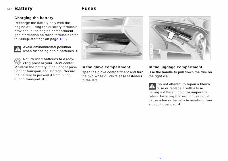
132nBattery Fuses
luggage compartmente handle to pull down the trim on ht wall.
In theUse ththe rig
394d
e678
Do not attempt to repair a blown fuse or replace it with a fuse g a different color or amperage . Installing the wrong fuse could a fire in the vehicle resulting from uit overload.<
havinratingcausea circ
Charging the battery Recharge the battery only with the engine off, using the auxiliary terminals provided in the engine compartment (for information on these terminals refer to "Jump-starting" on page 133).
Avoid environmental pollution when disposing of old batteries.<
Return used batteries to a recy-cling point or your BMW center.
Maintain the battery in an upright posi-tion for transport and storage. Secure the battery to prevent it from tilting during transport.<
In the glove compartmentOpen the glove compartment and turn the two white quick-release fasteners to the left.
390d
e085

133n
Over
view
Cont
rols
Mai
nten
ance
Use one jumper cable (+) to con-nect the positive terminal of the battery in the support vehicle with the auxiliary positive terminal pro-vided in the engine compartment of
Jump-starting
Do not use spray starter fluids to start the engine.
When your battery is discharged you can used two jumper cables to start your vehicle with power from the bat-tery in a second vehicle. You can also use the same method to help start another vehicle. Use only jumper cables with fully insulated handles on the ter-minal clamps.
Do not touch high-voltage wiring and cables on a running engine.
There is a risk of fatal injury if you do this. Carefully observe the following instructions to avoid personal injury and/or damage to one or both vehi-
1. Ensure that the battery in the sup-port vehicle is also rated at 12 volts. This information is pro-vided on the top of the battery casing
2. Do not disconnect your battery fromyour vehicle's electrical system. Switch off all electrical accessoriesin both vehicles
3. Make absolutely certain that there is no contact between the body-work of the two vehicles – short circuit hazard
4. Start the engine on the support vehicle and allow it to run
Repa
irs
Data
Inde
x
your BMW specifically for jump-starting. The cover of the auxiliary terminal for use in jump-starting your BMW is identified by a "+" symbol, refer to illustration. Flip the cap out to open
cles.<
-
5.
39m
de1
12

134nJump-starting
6. Next, connect one end of the other jumper cable (–) to either the sup-port vehicle's negative battery ter-minal or a suitable ground on its
390d
e146
7. Start the support vehicle's engine and let it run at an increased idling speed for a few minutes. Start the engine on the vehicle needing the jump-start, and allow it to run as usual. If the first start attempt is not successful, wait a few minutes before another attempt in order to allow the discharged battery to recharge
8. Before disconnecting the jumper cables let the engines run for a few minutes
9. Then disconnect the jumper cables in reverse sequence.
Depending on the cause of the fault,
engine or bodywork. Connect the other end to the negative battery terminal or a suitable ground on the vehicle being started. There is a special nut on the strut dome of your BMW (refer to the arrow in the illustration)Always adhere to this sequence when connecting jumper cables;
failure to observe this procedure can lead to sparks at the battery terminals and pose an injury hazard.<
have the battery recharged by your BMW center.

135n
Over
view
Cont
rols
Mai
nten
ance
Towing the vehicle
Keep the vehicles in line and avoid towing at an offset angle. Ensure
the tow rope connecting the two icles is tight, with no slack, before ting off.<
The towed vehicle should always be the lighter of the two vehicles.
is is not the case, it is no longer sible to control vehicle response.<
-starting better to start the vehicle's engine ump-starting. For instructions on p-starting, refer to page 133.
er attempt to use your vehicle to
n
ot-
thatvehstar
If thpos
TowIt isby jjum
Nev
Repa
irs
Data
Inde
x
h another vehicle, as damage to the rgy-absorbing bumpers could lt.
, rol se s-
f es
puseneresu
Tow fittingThe screw-in tow fitting is stored in the onboard tool kit; be sure that it remains in the vehicle at all times. This fitting
390d
e087
Rear:Apply pressure to the arrow symbol othe cover; remove the cover.
Screw the tow fitting in until it b394d
e088
is designed for installation in the tow sockets located at the front and rear of the vehicle, and is intended for towing on proper road surfaces only. It should not be used to pull a vehicle out of deep snow, mud, sand, etc. Always observe all applicable towing laws and regulations.
Access to tow sockets Front:Apply pressure to the arrow symbol on the cover; remove the cover.
toms firmly. Failure to screw thefitting in securely can lead to thread damage. Never attach tie-down hooks, chainsstraps, or tow hooks to tie rods, contarms, or any other part of the vehiclesuspension, as severe damage to thecomponents will occur, leading to posible accidents.<
Use only a nylon towing strap to towthe vehicle. The inherent resilience othis material helps protect both vehiclfrom sudden jerking movements.

136nTowing the vehicle
tt
Towing a vehicle1. Shift lever in neutral2. Towing speed:
Max. 45 mph (70 km/h)3. Towing distance:
Max. 95 miles (150 km/h)4. Leave the ignition key in position 1
to ensure that the brake lamps, turn signals, horn and windshield wipers remain operative, and to prevent the steering lock detent from engaging
5. Switch on the hazard-warning system (comply with official regula-tions).
Find some means of identifying the vehicle in tow, for instance, place a sign
Towing with a commercial tow truck>Do not tow with sling-type equipmen>Use a wheel-lift or flatbed equipmen
380us1
24
or warning triangle in the rear window.
Make sure that the ignition key remains in position 1 even if the
electrical system has failed to prevent the steering lock from engaging. The steering and brakes are without power assist when the engine is not running. This means that increased effort is required for steering and braking.<
>Please comply with applicable towinglaws.
Never allow passengers to ride ina towed vehicle for any reason.<

137n
Over
view
Cont
rols
Mai
nten
ance
Repa
irs
Data
Inde
x

138n

139n
Over
view
Cont
rols
Mai
nten
ance
Repa
irs
Data
dex
Overview
Controls and features
Operation, maintenance
Owner service procedures
Index
Technical data
In
Index
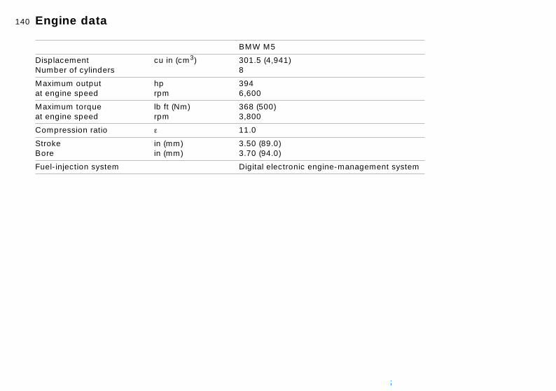
140n
t system
Engine data
BMW M5
DisplacementNumber of cylinders
cu in (cm3) 301.5 (4,941)8
Maximum outputat engine speed
hprpm
3946,600
Maximum torqueat engine speed
lb ft (Nm)rpm
368 (500)3,800
Compression ratio e 11.0
StrokeBore
in (mm)in (mm)
3.50 (89.0)3.70 (94.0)
Fuel-injection system Digital electronic engine-mana
gemen
141n
Over
view
Cont
rols
Mai
nten
ance
Repa
irs
Data
Inde
x.: 38.1 ft (11.6 m)
Dimensions
All dimensions are given in inches (mm). Minimum turning cir
39m
us0
03
cle dia

142nWeights
cluded) 5)
0)
0)
5)
BMW M5
Curb weight (with one person, ready for operation, full tank of fuel, options not inlbs. (kg) 4,024 (1,82
Approved gross vehicle weight lbs. (kg) 5,049 (2,29
Approved front axle load lbs. (kg) 2,426 (1,10
Approved rear axle load lbs. (kg) 2,701 (1,22
Approved roof load capacityApproved axle loads and approved gross vehicle weight may not be exceeded.
lbs. (kg) 220 (100)
Luggage compartment capacity cu ft (liters) 16.2 (460)

143n
Over
view
Cont
rols
Mai
nten
ance
Capacities
tes
l specification: page 22
details: page 115
details: page 117
W High Performance Synthetic ," for details: page 117
change at the 1,200-mile-service, n the oil never needs to be nged again
No
70) 0)
Fue
.5)
.0)
.0)
For
For
"BMOil
Oilthecha
Repa
irs
Data
Inde
x
Fuel tank of which reserve
gal. (liters)gal. (liters)
approx. 18.5 (approx.approx. 2.5 (approx. 1
Windshield washer systemwith headlamp washer system Intensive cleaning system
quarts (liters)quarts (liters)quarts (liters)
approx. 3.7 (approx. 3approx. 6.3 (approx. 6approx. 1.1 (approx. 1
Cooling system including heater circuit
quarts (liters) 12.7 (12.0)
Engine oil filter change quarts (liters) 6.9 (6.5)
Manual transmission and differential –

144n

145n
Over
view
Cont
rols
aint
enan
ce
Overview
Controls and features
Operation, maintenance
MRe
pair
sDa
tade
x
Owner service procedures
Index
Technical data
In
Index

Everything from A to Z
AA
AAA
A
AAAAAA
41
12
Bulbs and lamps 124
C California Proposition
65 Warning 120 Capacities 143 Car telephone 97 Cargo loading 102 Cellular phone 97
refer also to the separate Owner's Manual 97
BS (Antilock Brake System) 17, 107 ctivated-charcoal filter 91 ctive seat 43 dding brake fluid 118t engine coolant 118t engine oil 116t washer fluid 115t djusting backrest 41
Ashtray front 97 rear 98
Attach vacuum cleaner 98 AUC (Automatic recircu-
lated-air control) 90 Automatic climate
control 87 removing condensation from the windows 89
Automatic cruise control 61 Automatic curb monitor 46
B Backrest, adjustingBackup lamps 59
bulb replacementBattery 131
care 131 charging 131 discharged 133t
Belts 44 Beverage holder 97Blower 89 BMW active seat 43
headmirrseatsteetempir coir disir preir supirbaglarm
2 nce
1
7
Center (high mount) brake lamp 127
Central locking system 26 key 31
Charging the battery 132t CHECK button 66 Check Control 66 Check engine oil
level 115t Check tire inflation
pressure 22t, 109 Child seats 51 Child-restraint
restraints 43 ors 48 s 40 ring wheel 47 erature 89
nditioning 90 tribution 89 ssure, tires 22, 109 ply 89 s 17, 49 system 35 rage points
Automatic dimming exterior mirror 48 interior rearview mirror 48
Automatic recirculated-air control (AUC) 90
Automatic steering wheel adjustment 47
Automatic windshield washer 60
Average fuel consumption 75
Average speed 76
BMW comfort seat 4BMW High Performa
Synthetic Oil 117 BMW M sport seat 4BMW Maintenance
System 119 BMW Universal
Transmitter 93 Bottle holder, refer to
Beverage holder 9Brake fluid 118
disposal 118
m,08
106
installation 53 Child-restraint system with
tether strap 52 Cigarette lighter 98 Clock 70
refer also to the "Owner's Manual for Onboard Computer"
Anchochild-restraint system with tether strap 52
Antifreeze 118 Antilock Brake System
(ABS) 17, 107 Aquaplaning 107, 109
Avoiding unintentional alarms 36
Axle loads 142
Brake hydraulic systebrake pads 16
Brake system 108 brake fluid level 1brake linings 108 malfunctions 108t
Break-in procedures
6t

Everything from A to Z 147n
Over
view
Cont
rols
ce
nt
est 99
27 8
Electrical malfunction doors 27t fuel filler door 20t luggage compartment lid 32t sliding/tilt sunroof 39t
Elements of operation 14 Emergency release of
luggage compartment lid from luggage compartment's interior 34
Engine compartment 114 Engine coolant 118
Cockpit 14 Code 76
activating 76 deactivating 76 refer also to the "Owner's Manual for Onboard Computer" selecting 76
Comfort seat 42 Compartments 96 Computer 73
refer also to the "Owner's Manual for Onboard
Cup holder, refer to Beverage holder 97
Curb weight 142
D Date
calling up 70 changing 70 refer also to the "Owner's Manual for Onboard Computer"
Daytime driving lamps 84
Displays, instrumecluster 15
Disposal brake fluid 118 coolant 118 engine oil 116
Distance from destination 74
Divided rear backrDoor key 26 Doors
manual operationremote control 2
Mai
nten
anRe
pair
s
cking 27 s 110 bility
ntrol
ontrol 81 ontrol
temperature gauge 65 Engine data 140 Engine oil
checking level 115 consumption 115 dipstick 115 disposal 116 grades 117 level 16 pressure 16 temperature gauge 64
Engine performance 140
Computer" remote control 77
Configuring individual settings 55
Consumption 75 Convenience operation of
windows and sliding/tilt sunroof 27
Coolant 117 disposal 118
Coolant temperature gauge 65
DBC (Dynamic Brake Control) 17, 80
Deactivating interior motion sensor 36 tilt alarm sensor 36
Deep water 107 Defrosting position 89 Defrosting the
windows 89t Digital clock 70
refer also to the "Owner's Manual for Onboard Computer"
unlocking and loDOT Quality GradeDriving notes 107DSC (Dynamic Sta
Control) 17, 80 Dynamic Brake Co
(DBC) 17, 80 Dynamic Driving CDynamic Stability C
(DSC) 17, 80
E
Data
Inde
x
CooCopCovCruiCrui
dows 36 exterior
Estimated time of arrival 75 Exterior mirrors 48
automatic dimming 48 electrical heating 48
ling, maximum 90 yright 4 er, roller sun blinds 92 se control 61 sing range 75
Dimensions 141 Disconnecting the
battery 133t Displacement 140 Display lighting 85
Electric power winElectrical heating,
mirror 48

Everything from A to Z
sis0 09
11
ion
K Key Memory 55 Key with remote control 26 Keys 26
L Lamps and bulbs 124 Lashing eyes for attaching
cargo straps 34, 102 Length 141 License plate lamps, bulb
F Failure messages 66 Filling capacities 143 First-aid kit 20 Fittings, tow starting and
towing 135t Flashlight 96 Flat tire 109 Flat Tire Monitor 82 Flat tire, repairing 128 Fog lamps 85
bulb replacement 126t
H Handbrake 17, 58 Hands-free system 97 Hazard warning triangle 20 Head protection airbags 49 Head restraints 43
adjusting 43 Headlamp cover,
care 125t Headlamp flasher 59 Headlamp washer
system 115
Hydraulic Braking Asrefer to DBC 17, 8
Hydroplaning 107, 1
I Ice warning 63 Identification, tires 1Ignition key 26 Ignition lock 56 Imprint 4 Independent ventilat
rked-em 92
9
5 5
nboard 121
replacement 127t Lighter 98 LIGHTS ON warning 84 Locking and unlocking the
doors 27 Low beams 14, 84 Low-fuel warning lamp 64 Luggage compartment 34
capacity 142 manual operation 32t opening from the inside 33 opening separately 32
Folding rear backrest 99 Follow me home lamps 84 Frost protection,
radiator 118 Fuel consumption 75
average 75 Fuel filler door 20
manual operation 20t Fuel gauge 64 Fuel quality 22 Fuel specifications 22 Fuel tank capacity 143
Headlamp washers 61 Headrests 43 Heated seats 46 Heating with vehicle
stopped 90 Heavy cargo 102 Height 141 Height adjustment
seats 41 steering wheel 47
High beams 18, 59, 85 High Performance Synthetic
system, refer to Pacar ventilation syst
Indicator lamps 16 Inflation
pressure 22t, 10INSPECTION 65 Instrument cluster 1Instrument lighting 8Intensive cleaning
system 115 Interface socket for O
Diagnostics (OBD)Interior lamps 86
r 36
securing separately 32
Fuse replacement 132tG Gasoline gauge 64 Gasoline quality 22 Glove compartment 96 Gross vehicle weight 142
Oil 117 High-mount brake lamp 127 Holder for canned
beverages 97 Hood 113
release 113t Horn 14
Interior mirrors 48 Interior motion senso
deactivating 29
J Jump-starting 133t
tant,

Everything from A to Z 149n
Over
view
Cont
rols
ce
, reWa letarre B t ls) to
17
24t g
Passenger-side mirror tilt function 46
PDC Park Distance Control 78
Performance Recognition for M Dynamic Driving Control 81
Pocket flashlight 96 Pollen filter 91 Power seat 41 Power windows 36
safety switch 37 Pressure monitor, tires 82
Luggage compartment lid 32 emergency release from luggage compartment's interior 34 opening from the inside 33 opening from the outside 33 remote control 29 securing separately 32 unlocking in case of electrical
Manual transmission 58 Maximum cooling 90 Memory, adjustment of seat,
mirror, steering wheel 45 Microfilter 91 MID (Multi-Information
Display) 69 Mirrors 48
adjusting 48 heating 48 position adjustment memory 45 self-defrosting 48
Oil change intervalthe Service and Information Bookmodels) or the Wand Service Guid(Canadian mode
Oil pressure, indicalamp 16
Oil specification 1OILSERVICE 65 Onboard tool kit 1Opening and closin
from inside 31
Mai
nten
anRe
pair
s
mLugLugLum
M M D
CM MM+MaMaMa
re
trol
ion
"Owner's
Pressure, tires 22t, 109
Q Quality grades, tires 110
R Rain sensor 60 Reading lamps 86 Rear backrest, folding 99 Rear window defroster 90 Rearseat backrest,
folding 99
alfunction 32t gage net 34 gage straps 34 bar support 41
ynamic Driving ontrol 81 obility system 128
S tires 112 intenance 65, 119t lfunction displays 66
Modifications, technical 120
Multifunction buttons, steering wheel 19
Multifunction switch 59 Multi-Information Display
(MID) 69
O OBD interface socket 121 Odometer 63 Oil
from outside 27with the key 27
Outside temperatudisplay 63
P Park Distance Con
(PDC) 78 Parked-car ventilat
system 92 activating 72 refer also to the
Data
Inde
x
ard
58 84
Rearview mirrors 48 Recirculated-air mode 90 Refueling 20
nual operation doors 27t fuel filler door 20t luggage compartment lid 32t sliding/tilt sunroof 39t
additives 116 checking level 115 consumption 115 grades 117
Manual for OnboComputer"
Parking brake 17,Parking lamps 14,
fer to rranty (US anty ookle
r

Everything from A to Z
R
RRRR
RRR
R
RR
RRRR
SSSSS
S
po
cs o
1
Summer tires 111 Switching off the engine 57 Symbols 8
T Tachometer 64 Tail lamps 126
bulb replacement 126t Tank capacity 143 Technical
modifications 120
eleasing the fuel filler door after an electrical malfunction 20t eminder signal (Memo) 71 emote control 28, 77 emote control key 26 emoving condensation from windows 89t epairing flat tire 128 eplacement key 26t eplacement of lamps and bulbs 124t
Seats 40 adjusting 40 heating 46 position adjustment memory 45
Securing cargo 34, 102 Service and Warranty 10 Service and Warranty Infor-
mation Booklet (US models) 119
Service Interval Display 65, 119
Socket for attaching supplies 98
Spare key 26 Speakers 97 Special characteristi
winter tires 112 Special oils 117 Specified engine oilsSpeed 76
average 76 Speed limit 73 Speedometer 15
eplwipepoesesysesidolleoofoofrac
aaaa
e
85 56 t
ent 47
t
multi-
Telephone preparation 97 Temperature display
engine coolant 65 engine oil 64 outside temperature 63
Temperature gauge coolant 65 engine oil 64
Temperature layering 91 Tether strap 52
child-restraint system 52 Thigh support
adjustment 41
acement of windshield er blades 124t rting safety defects 10 rvoir, washer tem 115t ual heating mode 90 r sun blinds 92 load capacity 142 -mounted luggage k 103
Setting alarm in an emergency 77
Side airbags 49 Side Impact Head Protection
System 49 Side-marker lamps 84 Sitting safely 40
with airbags 40 with safety belt 40
Ski bag 100 Sliding/tilt sunroof 38
closing after an electrical
Sport seat 41 Standing lamps 14, Starting the engine
assistance 133tproblems 57, 133
Starting, vehicle 56 Steering wheel 47
automatic adjustmlock 56 position adjustmenmemory 45
Steering wheel with
9wner's d
ts 96
Third brake light 127 Through-loading system 99 Tilt alarm sensor 36
deactivate 29 Tilt function, passenger-side
mirror 46
fety belts 44 fety buttons 31 fety defects, reporting 10 fety switch for power windows 37 at heating 46
malfunction 39t convenience operation 27 power loss or malfunction 39t
Snow chains 112
function buttons 1Stopwatch 71
refer also to the "OManual for OnboarComputer"
Storage compartmen
wer
f
17

Everything from A to Z 151n
Over
view
Cont
rols
ce
ead
60
ice n
t
X Xenon lamp 125
Time calling up 70 changing 70 refer also to the "Owner's Manual for Onboard Computer"
Time of arrival, estimated 75
Timer 70 Tire
condition 109 damage 109t inflation
Trip odometer 63 Trunk, refer to Luggage
compartment 32 Turn signal indicator 18, 59
bulb replacement 125t Turning circle 141
U Uniform Tire Quality Grading
(UTQR) 110 Universal Transmitter 93 Use antifreeze,
W Warm feet – cool hWarning lamps 16Warning messagesWarning triangle 2Warranty and Serv
Booklet (Canadiamodels) 119
Washer fluids 115Washer reservoir,
filling 115t Washer system 60
Mai
nten
anRe
pair
s
107 he
1
ration 27
60 115t
pressure 22t, 109 labeling 111 pressure monitor 82 replacement 110 tread 109
Tire Quality Grading 110 Tools 124t Torque 140 Tow fittings 135t Towing the vehicle 135t Track 141 Traction Control System,
radiator 118t Used batteries 132
V Vehicle battery 131 Vehicle key 26 Vehicle Memory 55 Ventilation 91 Ventilation in the rear 91 Ventilation while parked
activating 72 refer also to the "Owner's Manual for Onboard
Water on the roadsWear indicator in t
tires 109 Weights 142 Wheel and tire
combinations 11Wheelbase 141 Width 141 Windows 36
convenience opedefrosting 89
Windshield washerreservoir, filling
Data
Inde
x
60
ine 3t
refer to DSC 80 Transmitter key 26 Transporting children
safely 51 Tread depth, tires 109 Tread wear indicator 109
Computer" Ventilation while parked,
refer to Parked-car venti-lation system 92
Ventilation, draft-free 91
Windshield wiperWinter tires 112 Wiper system 60 Working in the eng
compartment 11
91
6
Guide

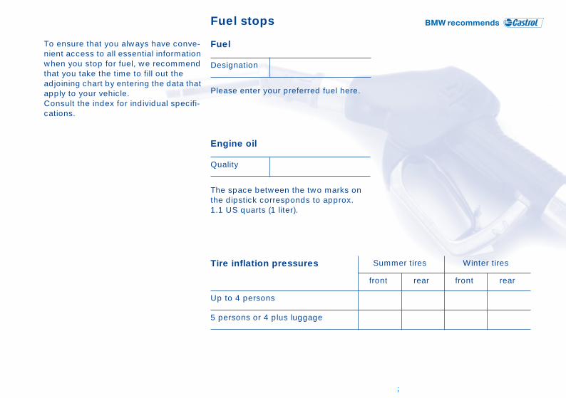
Fuel stops
To ensure that you always have conve-nient access to all essential information when you stop for fuel, we recommend that you take the time to fill out the adjoining chart by entering the data that apply to your vehicle.Consult the index for individual specifi-cations.
Fuel
Please enter your preferred fuel here.
Engine oil
The space between the two marks on the dipstick corresponds to approx.
Designation
Quality
mer tires Winter tires
rear front rear
1.1 US quarts (1 liter).
Tire inflation pressures
Up to 4 persons
5 persons or 4 plus luggage
Sum
front

The UltimateDriving Machine
01
41
0 1
56
83
0 u
e
More about BMW
bmwusa.com

M5
US
-En