Embed Size (px)
Citation preview
PLAN OF DEVELOPMENT
FOR THE RHYOLITE RIDGE 2 SOLAR PROJECT
Prepared for: Bureau of Land Management
Tonopah Field Office 1553 South Main Street, P.O. Box 911
Tonopah, NV 89049
Prepared by: Transcon Environmental, Inc.
1942 University Avenue, Suite 206 Berkeley, California 94704
June 11, 2021

Rhyolite Ridge 2 Solar Project June 11, 2021 Draft Plan of Development ii
TABLE OF CONTENTS
Abbreviations ................................................................................................................................... v
1.0 Overview .............................................................................................................................. 7
1.1 BLM Purpose and Need .................................................................................................... 7
1.2 Applicants Purpose and Need .......................................................................................... 8
1.3 Project Location................................................................................................................ 8
1.4 Legal Description .............................................................................................................. 9
1.5 Major Users Along the Route ........................................................................................... 9
2.0 Project Description .............................................................................................................. 9
3.0 Project Elements .................................................................................................................. 9
3.1 Solar Facility Elements ..................................................................................................... 9
3.2 Gen‐Tie Transmission Line Elements ............................................................................. 12
3.3 Project Feature Specifications and Disturbance Areas .................................................. 14
3.4 Safety Requirements ...................................................................................................... 16
4.0 Construction of the Facilities ............................................................................................. 16
4.1 Geotechnical Investigation ............................................................................................. 16
4.2 Site Engineering Surveys ................................................................................................ 17
4.3 Timing of Activities ......................................................................................................... 17
4.4 Access Roads .................................................................................................................. 17
4.5 Transmission Structure Erection Sites ........................................................................... 18
4.6 Conductor Pulling and Tension Sites .............................................................................. 18
4.7 Water Use ....................................................................................................................... 18
4.8 Industrial Wastes and Toxic Substances ........................................................................ 19
4.9 Construction Traffic ........................................................................................................ 19
4.10 Fire Protection ............................................................................................................ 19
4.11 Vegetation Removal, Site Clearing, Grading, and Excavation .................................... 20
4.12 Gravel, Aggregate, and Concrete ............................................................................... 20
4.13 PV Solar Array Assembly and Construction ................................................................ 20
4.14 Site Stabilization, Protection, and Reclamation ......................................................... 21
5.0 Operations and Maintenance ............................................................................................ 21
5.1 Solar Facility Operations and Maintenance ................................................................... 21
5.2 Gen‐Tie Operations and Maintenance ........................................................................... 23

Rhyolite Ridge 2 Solar Project June 11, 2021 Draft Plan of Development iii
5.3 Vegetation Treatment .................................................................................................... 23
6.0 Decommissioning ............................................................................................................... 23
7.0 Design Features .................................................................................................................. 24
8.0 Government Agencies Involved ......................................................................................... 24
8.1 Bureau of Land Management ........................................................................................ 24
8.2 Nevada Department of Transportation ......................................................................... 25
8.3 Nevada Division of Environmental Protection ............................................................... 25
8.4 United States Army Corps of Engineers ......................................................................... 26
8.5 United States Fish and Wildlife Service .......................................................................... 26
8.6 Local Compliance ............................................................................................................ 26
9.0 Resource Values and Environmental Concerns ................................................................. 26
9.1 Biological Resources ....................................................................................................... 27
9.2 Vegetation and Protected Native Plants ........................................................................ 29
9.3 Noxious and Invasive Species ......................................................................................... 29
9.4 Cultural Resources.......................................................................................................... 29
9.5 Lands and Realty ............................................................................................................ 31
9.6 Air Quality/Climate Change/Greenhouse Gases ............................................................ 32
9.7 Noise ............................................................................................................................... 33
9.8 Visual Resources ............................................................................................................. 33
9.9 Water Resources ............................................................................................................ 34
9.10 Clean Water Act/Section 404 Compliance ................................................................. 34
9.11 Clean Water Act/Section 402 Compliance ................................................................. 34
9.12 Ground Water ............................................................................................................. 35
9.13 Wilderness Characteristics ......................................................................................... 35
9.14 Hazardous Materials ................................................................................................... 35
9.15 Rangeland Resources .................................................................................................. 35
9.16 Farmlands (Prime or Unique) and Soil Resources ...................................................... 35
10.0 References ......................................................................................................................... 37
FIGURES AND TABLES FIGURES
Figure 1 Location map............................................................ Error! Bookmark not defined.

Rhyolite Ridge 2 Solar Project June 11, 2021 Draft Plan of Development iv
TABLES
Table 1 Temporary and permanent disturbance on BLM‐managed lands ....................... 15
Table 2 Temporary and permanent disturbance within the NDOT‐administered ROW for Highway 265 .......................................................................................................... 15
Table 3 BLM Sensitive and other special status species potentially occurring in or near the project area .................................................................................................... 28
APPENDICES
Appendix A Location Map Appendix B Project Layout

Rhyolite Ridge 2 Solar Project June 11, 2021 Draft Plan of Development v
ABBREVIATIONS 4x4 four‐wheel‐drive AC alternating current AF acre‐feet AFY acre‐feet per year AML Appropriate Management Level APE area of potential effects ATV all‐terrain vehicle AU animal unit AUM animal unit month BESS battery energy storage system BLM Bureau of Land Management BMD Battle Mountain District BMP best management practice CFR Code of Federal Regulations CGP Construction General Permit CWA Clean Water Act DC direct current EPA Environmental Protection Agency ESA Endangered Species Act FLPMA Federal Land Policy and Management Act FPPA Farmland Protection Policy Act gen‐tie electrical generator intertie GHG greenhouse gas GLO General Land Office HAP Hazardous Air Pollutant HMA Herd Management Area IOP Interagency Operating Procedures IPaC Information for Planning and Consultation IVM Integrated Vegetation Management kV kilovolt MDBM Mount Diablo Base Meridian MW megawatt MWac megawatt alternating current

Rhyolite Ridge 2 Solar Project June 11, 2021 Draft Plan of Development vi
NAAQS National Ambient Air Quality Standards NDEP Nevada Division of Environmental Protection NEPA National Environmental Policy Act NDOT Nevada Department of Transportation NEMA National Electric Manufacturers Association NHPA National Historic Preservation Act NRHP National Register of Historic Places NRS Nevada Revised Statute NVCRIS Nevada Cultural Resource Information System O&M operation and maintenance PM2.5 Particulate matter with a diameter of less than 2.5 micrometers PM10 Particulate matter with a diameter of less than 10 micrometers POCO Point of Change of Ownership PV photovoltaic ROW right‐of‐way RTU remote terminal unit SCADA Supervisory Control and Data Acquisition SWPPP Stormwater Pollution Prevention Plan TFO Tonopah Field Office USACE United States Army Corps of Engineers U.S.C. United States Code USFWS United States Fish and Wildlife Service VRM Visual Resource Management WWEC West‐Wide Energy Corridor WOUS Waters of the United States

Rhyolite Ridge 2 Solar Project June 11, 2021 Draft Plan of Development 7
1.0 OVERVIEW 336SP 8me LLC (Applicant), a subsidiary of 8minute Solar Energy proposes to construct, operate and maintain, and (eventually) decommission the Rhyolite Ridge 2 Solar Project (Project), consisting of an up to 600‐megawatt (MW) alternating current (MWac) solar photovoltaic (PV) power generating and battery energy storage system (BESS) facility (collectively, the solar facility) on approximately 6,810 acres in Esmeralda County, Nevada. The Project would be located on Bureau of Land Management (BLM)‐managed lands, specifically the Battle Mountain District (BMD), Tonopah Field Office (TFO). The Project would also construct, operate, and maintain an electrical generator intertie (gen‐tie) transmission line across BLM and private lands. The Rhyolite Ridge 2 Solar Project would connect to the regional electrical grid, specifically the proposed Greenlink West 525‐kilovolt (kV) transmission line (Greenlink West), at the proposed Esmeralda 525‐kV Substation via an overhead 525‐kV single‐ or double‐circuit gen‐tie line. The line would run east from the Project to Highway 265 before turning northwest to follow the highway for approximately 2.23 total miles to the proposed Esmeralda Substation, which would be located on BLM land in Esmeralda County at approximate latitude/longitude 37.943508, ‐117.733447. Underground or overhead collector lines would gather electricity generated by the solar arrays and deliver it to the Project substation. The collector lines would be located on BLM‐managed lands within the footprint of the solar facility, and the Project substation would be located on BLM‐managed lands. The collector lines would need to cross Highway 265 as well land administered by the Nevada Department of Transportation (NDOT). Components of the Project on BLM‐managed lands include the solar facility, the gen‐tie line, and 11 pole structures associated with the gen‐tie line, if constructed above ground. The gen‐tie line would require a BLM right‐of‐way (ROW) up to approximately 2.23 miles (11,780 linear feet) in length and 250 feet wide (67.6 acres). Portions of the gen‐tie line would be within the West‐Wide Energy Corridor (WWEC) utility corridor (P.L. 18‐224) (see Appendix A). 1.1 BLM Purpose and Need
In accordance with the Federal Land Policy and Management Act (FLPMA) (43 United States Code [U.S.C.] 1701), public lands are to be managed for multiple uses that consider the long‐term needs of future generations for renewable and non‐renewable resources. The BLM is authorized to grant ROWs on public lands for systems of generation, transmission, and distribution of electrical energy (§ 501[a][4]). Considering the BLM's multiple‐use mandate, the BLM’s purpose and need for this action is to respond to the ROW application submitted by the Applicant under Title V of FLPMA (43 U.S.C. § 1761) to construct, operate, maintain, and decommission the Project. The BLM would decide whether to deny the proposed ROW, grant the ROW, or grant the ROW with modifications. The BLM may include any terms, conditions, and stipulations it determines to be in the public interest, which may include modifying the proposed use or changing the location of the proposed facilities (43 Code of Federal Regulations [CFR] 2805.10(a)(1)). Several other agencies may be identified as cooperating and

Rhyolite Ridge 2 Solar Project June 11, 2021 Draft Plan of Development 8
participating agencies. The purpose and need for each of these agencies is to respond to authorization requests for permits and approvals to construct and operate the Project. 1.2 Applicant’s Purpose and Need
The fundamental purpose of the Project is to construct a clean, renewable source of solar electricity that helps meet the region’s growing demand for power and helps fulfill national and state renewable energy and greenhouse gas (GHG) emission goals. Solar energy provides a sustainable, renewable source of power that helps reduce fossil fuel dependence and GHG emissions. Considering the entire process, from raw material sourcing through end‐of‐life‐cycle collection and recycling, 600 MW of additional generating capacity would produce a small fraction of the GHG emissions of a fossil fuel plant with similar capacity. Specific Project objectives consist of the following:
• Establish a solar PV power‐generating facility that is of sufficient size and configuration to produce approximately 600 MWac of electricity in order to provide Nevada a significant new source of renewable energy.
• Produce and transmit electricity at a competitive cost. • Provide a means of conveying up to 600 MWac of renewable energy to the electric grid
to meet increasing demands for in‐state generation. • To compliment the Applicant’s dedication to environmental stewardship through
environmentally sensitive Project siting. • Locate the facility in the rural part of Esmeralda County in proximity to an available
connection to the existing electrical transmission infrastructure. • Minimize environmental effects by:
o Minimize and avoid Exclusion Areas, to the extent practicable, as identified in the Solar Programmatic Environmental Impact Statement Record of Decision;
o Using existing electrical transmission facilities, ROWs, roads, and other existing infrastructure where practicable;
o Minimizing water use during operation; o Reducing GHG emissions; and o Using solar technology that is available, cost‐effective, proven, efficient, easily
maintained, recyclable, and environmentally sound. 1.3 Project Location
The Rhyolite Ridge 2 Solar Project facility would be located on BLM land in Esmeralda County, Nevada, approximately 32 miles west/southwest of Tonopah, Nevada. The Project is comprised of a contiguous, irregular polygon approximately 1 mile southwest of Highway 265 in the Big Smoky Valley at its closest point (Appendix A). The Project would be located on BLM‐managed lands and would cross lands administered by NDOT.

Rhyolite Ridge 2 Solar Project June 11, 2021 Draft Plan of Development 9
The gen‐tie line would originate at the Project location on BLM‐managed lands. The line would then proceed east from the Project on BLM‐managed lands and would cross NDOT‐administered land, running northwest along Highway 265 before turning northeast to connect into the proposed Esmeralda Substation (Appendix A). The total length of the gen‐tie line is approximately 11,780 feet (2.23 miles). 1.4 Legal Description
The 6,810‐acre solar facility would be located on BLM‐managed lands in Township 01 North, Range 37 East (E), Sections 13, 14, 23, 24, 25, 26 and 36 as well as Township 01 North, Range 38 East, Sections16, 19, 20, 21, 29, 30, 31, 32, and 33, and Township 01 South, Range 38 East, Sections 3, 4, 5, 6, 9, 10, 11, 12, 13, and 14, and Township 01 South, Range 39 East, Sections 7, 17, 18, and 19, Mount Diablo Base Meridian (MDBM). The proposed gen‐tie line would run through Township 01 North, Range 38 East, Sections 15, 16, and 21, MDBM, ending at the proposed Esmeralda Substation in Section 15. 1.5 Major Users Along the Route
Existing electric transmission lines and Highway 265 are located near the solar facility and gen‐tie route on BLM‐ and NDOT‐administered lands. The solar field lands are vacant, with no signs of any grazing, agricultural, industrial, or mining activity within the Project area. There are a limited number of existing unimproved rural roads in the Project area. 2.0 PROJECT DESCRIPTION The Rhyolite Ridge 2 Solar Project involves construction, operation and maintenance (O&M), and (eventual) decommissioning of a 600‐MWac PV electricity generation and BESS facility on BLM‐administered lands. The gen‐tie line proposed for the Project would cross BLM‐managed and NDOT‐administered lands. The Project may include the following elements discussed in detail below: solar arrays comprised of PV panels and inverters, on‐site substation(s), underground electrical collector lines connecting the inverters to the onsite substation, O&M buildings, BESS, laydown yards, and other related infrastructure such as access roads, fences, and telecommunication systems (see Appendix A for site map and Appendix B for preliminary project layout plan). 3.0 PROJECT ELEMENTS The energy generated by the solar facility would be sold to a viable utility, commercial, or industrial off‐taker under a long‐term power purchase agreement, build‐own‐transfer agreement, or other like commercial purchase contract. The proposed Project would provide a direct connection between the solar facility substation and the proposed Esmeralda 525‐kV Collector Substation that is part of Greenlink West. 3.1 Solar Facility Elements

Rhyolite Ridge 2 Solar Project June 11, 2021 Draft Plan of Development 10
3.1.1 Solar Facility Access Roads Project access to the solar facility would occur on existing routes on BLM‐managed lands. Within the solar facility, access roads would be constructed to provide vehicle access to the solar equipment and collector lines. Some portions of the existing routes may require minor cleanup (e.g., vegetation removal, moving rocks and boulders, regrading of road surface, etc.) to accommodate the transport of Project equipment to the solar facility. After construction, access routes to the solar facility, along the gen‐tie line, and new routes constructed within the solar facility would continue to be utilized during O&M and decommissioning. These routes may require repair on an infrequent basis. 3.1.2 Solar Blocks Mounted PV solar panels, inverter stations, and transformers would be combined to form solar blocks. The solar blocks would be repeated to provide up to 600 MWac of electrical generating capacity. The electricity generated from the solar panels (direct electrical current [DC]) would be delivered through underground or overhead cables to an inverter station where the DC is converted to alternating electrical current. Inverter stations are generally located in the middle of each solar block. A transformer would then step up the voltage to 525 kV. The transformers would be contained in steel enclosures. The inverter stations could be contained in an enclosed or canopied metal structure on a skid or concrete‐mounted pad. The enclosures would be designed to meet National Electric Manufacturers Association (NEMA) 1 or NEMA 3R IP44 standards for electrical enclosures to contain any fire that could occur in structures. The enclosures would be constructed on 6 inches of stone with a filter fabric underlay, and each enclosure pad would be approximately 261 square feet in size. The Project would include 250 inverter stations for a total of approximately 1.5 acres. Solar panels would be installed on a single‐axis tracker oriented in rows that would rotate to follow the sun over the course of the day. Depending on the soil conditions within the solar facility, the wind load capacity of the solar panels, and the mounting structure supporting the solar panels, the foundations for the mounting structures would be embedded driven steel posts, or screw anchors only if soil conditions do not support driven posts. The mounting structures would extend approximately 12 inches below ground and may be encased in concrete or a small concrete footing. The layout of the solar blocks would be optimized for the desired energy production while accounting for site characteristics, such as soil conditions, site topography, and site hydrology. The solar panels would be up to 20 feet above ground at their highest point, which would occur during the morning and evening hours when the trackers are tilted at their maximum angle. Each solar block would be powered by a low‐voltage electric drive motor. The motors would typically be operated for a few seconds every 5 to 10 minutes during daylight conditions to move the panels in approximately 1‐degree increments. The preliminary layout includes 27,199 single‐axis tracker units (Appendix B). Meteorological monitoring stations would be located at multiple locations within the solar blocks to monitor wind speed and communicate with the trackers. This would allow the

Rhyolite Ridge 2 Solar Project June 11, 2021 Draft Plan of Development 11
trackers to rotate the panels to a flat position during high winds. Meteorological stations would be mounted on or near the inverter stations and are not expected to exceed 25 feet in height from the ground. 3.1.3 Project Substation The on‐site Project substation would contain several components, including auxiliary power transformers, distribution cabinets, revenue metering systems, a microwave transmission tower, voltage switch gear, a control building, and a mechanical electrical equipment room. The substation would occupy an area of approximately 2.62 acres and would be secured separately by an additional chain‐link fence. 3.1.4 Collector Lines Energy generated from the solar facility would be transferred to the Project substation through underground or overhead collector lines located within the solar facility. At the Project substation, the electricity would be stepped up again to 525 kV for delivery to the proposed Esmeralda Substation via the gen‐tie line. The collector lines would be installed in underground trenches approximately 4 feet deep and 6 feet wide, or on wooden or steel monopoles if constructed above ground. Horizontal boring may also be an option given the appropriate soil conditions and other factors. 3.1.5 Battery Energy Storage System The solar facility may include one or more BESSs. The BESSs would consist of modular and scalable battery packs and battery control systems that conform to national safety standards. The BESSs would be in pad‐mounted, stackable metal structures (approximately 40 feet long by 8 feet wide by 8 feet high) or a separate building in compliance with applicable regulations. The maximum height of a building, if used, is not expected to exceed 25 feet. The total acreage of the BESS would be approximately 33.3 acres. The dimensions and number of BESSs would vary depending on the application, supplier, chosen configuration, and applicable building standards. The BESSs would be within the solar facility area near the substation (Appendix B). 3.1.6 Site Fencing The Project site would be enclosed within a chain‐link perimeter fence, potentially with barbed wire, measuring up to 8 feet in height (from finished grade). The fence would have controlled access points, lighting, and possibly security alarms, security camera systems with remote monitoring, and security guard vehicle patrols to deter trespassing and/or unauthorized activities. The fence would be approximately 138,653 linear feet following the perimeter of the Project area on BLM‐managed lands.

Rhyolite Ridge 2 Solar Project June 11, 2021 Draft Plan of Development 12
3.1.7 Communication Systems Infrastructure Telecommunications systems would be installed at the transformers consisting of a remote terminal unit (RTU), communications line (i.e., T‐1 line), microwave receiver mounted on the building or on a lattice tower up to 130 feet tall, and miscellaneous communication cables and link equipment, as required. Fiber optics would be installed on the gen‐tie line to link the proposed Project to the proposed Esmeralda Substation. Support equipment (i.e., metering class current transformers and potential transformers) would also be installed to facilitate metering of all applicable energy outputs. The lattice structure may be erected within the solar facility to facilitate wireless communications to provide a back‐up option for site telecommunications. The Project would have a Supervisory Control and Data Acquisition (SCADA) system that would allow for the remote monitoring and control of inverters and other Project components. The SCADA system would be able to monitor Project output and availability and to run diagnostics on the equipment. This equipment would be in the O&M building and would connect to the communications system. 3.1.8 Operations and Maintenance Buildings The solar facility would include up to sixteen O&M buildings with on‐site parking. The O&M buildings would be storage containers (e.g., Connex Box) approximately 40 feet long by 8 feet wide. The O&M buildings could include offices, repair facilities/parts storage, a control room, and restrooms. A septic tank and leach field could be used for collection, treatment, and disposal of sanitary waste. If a septic system is not used, portable toilets would be provided instead. Additional components of the O&M facilities would include aboveground water storage tanks, signage, a flagpole, trash containers, and the SCADA system. The O&M buildings and components would be equipped with exterior lighting as approved by BLM. Minimal lighting would be used and would be directed downward and away from wildlife habitat. The O&M buildings would occupy approximately 0.1 acres of the Project area including area for the storage tanks and parking (see Section 3.1.8 for acreage). The design and construction of the buildings and associated water/wastewater systems would be consistent with Esmeralda County building standards and approved by the BLM. 3.1.9 Laydown Yards A temporary laydown yard/staging area of up to 11.56 acres would be established within the solar facility on BLM lands. The laydown yard would be used for parking and to stage equipment and materials during Project construction. 3.2 Gen‐Tie Transmission Line Elements
The gen‐tie line for the Rhyolite Ridge 2 Solar Project would be 2.23 miles (11,780 linear feet) in length, the majority of which is on BLM‐managed lands (2.21 miles). There would be 0.02 miles

Rhyolite Ridge 2 Solar Project June 11, 2021 Draft Plan of Development 13
(100 linear feet) of gen‐tie line within the NDOT‐administered ROW for Highway 265. The 2.21‐mile section of gen‐tie line on BLM would have a 250‐foot‐wide ROW and require ROW authorization from the BLM (totaling 67.0 acres). The 0.02‐mile portion crossing the NDOT‐administered ROW would require an easement. 3.2.1 Transmission Support Structures A total of 11 transmission support structures (all on BLM‐managed lands with up to two falling within the NDOT‐administered ROW for Highway 265) would be erected and would typically be spaced 700 to 1,200 feet apart (center to center), depending on the topographic, hydrologic, and geologic conditions of the underlying lands. Project design would attempt to not place any structures within the NDOT ROW. The gen‐tie line would require two dead‐end structures (one within the solar facility at the Project substation and one on BLM land at the proposed Esmeralda Substation). These structures would be composed of one or more steel poles with heights generally ranging from 90 to 150 feet. The minimum ground clearance of the conductor cable(s) would be 25 feet. Communications cable or fiber optic cable would also be installed on the transmission structures. The communications cable or fiber optic line would only be for communication purposes related to the Project and would not be sub‐leased. 3.2.2 Gen‐Tie Service Road The gen‐tie line was designed with an emphasis on occupying the smallest ground disturbance footprint practicable and sited to follow existing roads. The gen‐tie line is also designed to follow along the transmission corridor of the Greenlink transmission line. New access would also be constructed on BLM‐managed lands within the gen‐tie 250‐foot‐wide ROW for 11,780 linear feet and with a width of 20 feet (5.41 acres). Spur roads, if necessary, would be 12 feet wide and constructed from the main access roads and/or existing transmission structure footprints to provide access to work areas for new gen‐tie line transmission structures. These existing gen‐tie access roads within the BLM‐authorized ROW would require coverage under the ROW grant. The Project would also include existing access on BLM‐managed lands to access the gen‐tie ROW. The existing roads may require blading and improvements in certain areas like the methods described above in Section 3.1.1. 3.2.3 Point of Change of Ownership Structure The Applicant would be responsible for constructing the gen‐tie line from the Rhyolite Ridge 2 Solar Project to the dead‐end structure and 525‐kV switch outside of the proposed Esmeralda Substation, located in Township 01 North, Range 38 East, Section 15, MDBM, Nevada. This dead‐end structure at the proposed Esmeralda Substation is called the Point of Change of Ownership (POCO) structure and is the location where the ownership of the gen‐tie line changes from the Applicant to the electric utility that purchases the energy generated at the solar facility. From the POCO structure, the remaining transmission structures to the point of the interconnection terminal within the proposed Esmeralda Substation would be constructed by NV Energy.

Rhyolite Ridge 2 Solar Project June 11, 2021 Draft Plan of Development 14
3.2.4 Transmission Provider’s Interconnection Facilities The 525‐kV transmission structures would be installed with overhead conductor cable, including optical fiber composite overhead ground wire or equivalent, between the POCO structure and the proposed Esmeralda Substation. Dedicated relays and SCADA systems required for equipment protection and connection to fiber feeds would be installed at the proposed Esmeralda 525‐kV Switching Station for the gen‐tie line interconnection. 3.2.5 Fiber‐Optic Installation The new static fiber‐optic cable is manufactured in approximately 3.5‐ to 4‐mile reel lengths. Given the short length of the gen‐tie line (2.23 miles), a single reel would be used. The Project equipment for installing the cable would include a cable reel, a tensioner trailer pulled behind a line truck, and a four‐wheel‐drive (4x4) pickup truck. At the cable‐pulling end, the equipment would include a V‐groove cable puller (winch) either mounted on or pulled behind a line truck and a 4x4 pickup truck. 3.2.6 Telecommunications and Metering at the Esmerelda Substation Telecommunications would be installed consisting of an RTU and necessary communications equipment for the Project, including a multiplexer on the communications line (i.e., T‐1 line) and miscellaneous communication cables and link equipment, as required. Support equipment (i.e., metering class current transformers and potential transformers) would be installed inside the Project lease area to facilitate metering of all applicable energy outputs. All this equipment would be outside of the designated utility corridor. 3.3 Project Feature Specifications and Disturbance Areas
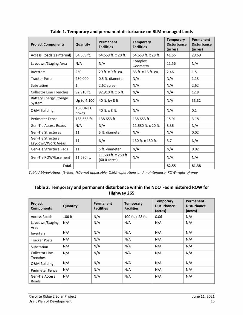
Permanent disturbance areas would be those areas where the surface of the ground is not restored to its existing condition after construction, such as those relating to foundations or new access roads. Temporary disturbance areas include those where construction activity would take place but where restoration of the surface would be possible, such as those relating to temporary work areas, pull sites, and laydown yards. In some places, areas of temporary disturbance would overlap with areas previously disturbed. Short‐term ROWs would also be required for areas beyond the permanent ROWs. These areas would be necessary to facilitate construction and the safe operation of equipment. The Project is estimated to result in approximately 81.38 acres of permanent disturbance and 82.55 acres of temporary disturbance on BLM‐managed lands with 0.65 acres of permanent disturbance and 0.06 acres of temporary disturbance on NDOT‐administered lands within the Highway 265 ROW. A summary of temporary and permanent disturbance on BLM‐managed lands and NDOT administered lands is provided in Tables 1 and 2 below.
Rhyolite Ridge 2 Solar Project June 11, 2021 Draft Plan of Development 15
Table 1. Temporary and permanent disturbance on BLM‐managed lands
Project Components Quantity Permanent Facilities
Temporary Facilities
Temporary Disturbance (acres)
Permanent Disturbance (acres)
Access Roads 1 (internal) 64,659 ft. 64,659 ft. x 20 ft. 64,659 ft. x 28 ft. 41.56 29.69
Laydown/Staging Area N/A N/A Complex Geometry 11.56 N/A
Inverters 250 29 ft. x 9 ft. ea. 33 ft. x 13 ft. ea. 2.46 1.5
Tracker Posts 250,000 0.5 ft. diameter N/A N/A 1.13
Substation 1 2.62 acres N/A N/A 2.62
Collector Line Trenches 92,910 ft. 92,910 ft. x 6 ft. N/A N/A 12.8 Battery Energy Storage System Up to 4,100 40 ft. by 8 ft. N/A N/A 33.32
O&M Building 16 CONEX boxes 40 ft. x 8 ft. N/A N/A 0.1
Perimeter Fence 138,653 ft. 138,653 ft. 138,653 ft. 15.91 3.18
Gen‐Tie Access Roads N/A N/A 11,680 ft. x 20 ft. 5.36 N/A
Gen‐Tie Structures 11 5 ft. diameter N/A N/A 0.02 Gen‐Tie Structure Laydown/Work Areas 11 N/A 150 ft. x 150 ft. 5.7 N/A
Gen‐Tie Structure Pads 11 5 ft. diameter N/A N/A 0.02
Gen‐Tie ROW/Easement 11,680 ft. 11,680 ft. x 250 ft (60.0 acres). N/A N/A N/A
Total 82.55 81.38
Table Abbreviations: ft=feet; N/A=not applicable; O&M=operations and maintenance; ROW=right‐of‐way
Table 2. Temporary and permanent disturbance within the NDOT‐administered ROW for Highway 265
Project Components Quantity Permanent
Facilities Temporary Facilities
Temporary Disturbance (acres)
Permanent Disturbance (acres)
Access Roads 100 ft. N/A 100 ft. x 28 ft. 0.06 N/A Laydown/Staging Area
N/A N/A N/A N/A N/A
Inverters N/A N/A N/A N/A N/A
Tracker Posts N/A N/A N/A N/A N/A
Substation N/A N/A N/A N/A N/A
Collector Line Trenches
N/A N/A N/A N/A N/A
O&M Building N/A N/A N/A N/A N/A
Perimeter Fence N/A N/A N/A N/A N/A
Gen‐Tie Access Roads
N/A N/A N/A N/A N/A

Rhyolite Ridge 2 Solar Project June 11, 2021 Draft Plan of Development 16
Project Components Quantity Permanent
Facilities Temporary Facilities
Temporary Disturbance (acres)
Permanent Disturbance (acres)
Gen‐Tie Structures
N/A N/A N/A N/A N/A
Gen‐Tie Structure Laydown/Work Areas
N/A N/A N/A N/A N/A
Gen‐Tie Structure Pads
N/A N/A N/A N/A N/A
Gen‐Tie ROW/Easement
100 ft. 100 ft. x 250 ft. N/A N/A 0.6
Total 0.06 0.65
Table Abbreviations: ft=feet; N/A=not applicable; ROW=right‐of‐way 3.4 Safety Requirements
Safety precautions and emergency systems would be implemented as part of the design and construction of the Project to ensure safe and reliable operation. Administrative controls may include classroom and hands‐on training in operating and maintenance procedures, general safety items, and a maintenance program plan. These controls would complement Project design and monitoring features to enhance safety and reliability. 4.0 CONSTRUCTION OF THE FACILITIES 4.1 Geotechnical Investigation
Prior to construction, geotechnical surveys would be conducted to provide information for foundation designs and transmission structures. The geotechnical studies would allow for observations of subsurface conditions, and soil samples would be obtained for laboratory testing and soil classification. Results of the analysis would help inform several design‐related parameters, including cement types and corrosion protection of foundation elements. The subsurface exploration program would involve drilling borings with a rubber tire 4x4 drill rig or similar equipment. A 4x4 side‐by‐side all‐terrain vehicle (aka ATV or gator) and/or pickup trucks would be used to drive support personnel to boring locations. During the borings, drive samples would be obtained from the subsurface for laboratory testing. If necessary, test pits would also be conducted using a standard rubber tire backhoe equipped with a 24‐inch bucket, or similar equipment. No personnel would enter the test pits. About 15 gallons (three 5‐gallon buckets) of material would be collected from the surface to a depth of 1 foot at select test pit locations (not all test pits would be sampled). These samples may be tested in the laboratory for gradation, plasticity, maximum density, thermal resistivity, and corrosion characteristics. Each test pit would be backfilled immediately upon completion; no excavation would be left open.

Rhyolite Ridge 2 Solar Project June 11, 2021 Draft Plan of Development 17
Field resistivity testing may also be conducted, if necessary. The field resistivity testing would be non‐intrusive. Four steel pin electrodes (about the size of tent stakes) would be driven by hand into the ground about 4 inches deep, and an electrical current would be induced between the two outer electrodes. The two inner electrodes would be used to record the electrical resistivity of the current going through the earth. 4.2 Site Engineering Surveys
On‐ground investigations would be completed to accurately locate the Project components, Project boundaries, and the centerline of the gen‐tie within the ROW. Prior to construction, the limits of the ROW, work areas, and access roads would also be flagged. All construction activities would be confined to these areas to prevent unnecessary impacts from affecting sensitive areas. The locations of underground utilities would be located, staked, and flagged to guide construction activities. 4.3 Timing of Activities
Construction would generally occur between 5 a.m. and 5 p.m., Monday through Friday, but could occur 7 days a week. Additional hours may be necessary to make up schedule deficiencies or to complete critical construction activities. For instance, during hot weather, it may be necessary to start work earlier (as early as 3 a.m.) to avoid work during high ambient temperatures. Also, construction would require some nighttime activity for installation; refueling equipment; staging material for the following day’s construction activities; service or electrical connection; or inspection, quality assurance/control, and testing activities. Nighttime activities would be performed with temporary lighting. Some activities may require construction activities 24 hours per day, 7 days per week. 4.4 Access Roads
Existing roads would be used to access the construction site wherever feasible. Access from the east would come from Highway 265. There are several existing unnamed dirt two‐track roads which cross the Project, but a new access road would be created along the eastern project perimeter. Construction of the gen‐tie would begin with improvements to existing access roads or construction of new 20‐foot‐wide maintenance roads within the 250‐foot‐wide gen‐tie ROW, where necessary, and establishment of spur roads where needed to the new structures. Spur roads would typically be 12 feet wide and may be bladed. If necessary, new roads would be compacted to ensure stability. All equipment, permanent materials, and commodities for the Project would be transported to the site via rail and/or local highways. Any shipments by railroad would go to the nearest active railroad spur for offloading and transportation by truck to the Project site. All equipment and material deliveries would utilize the previously approved site access route. Truck deliveries of equipment and materials would occur from the initial construction notice to proceed through the entire duration of the Project. Initial truck deliveries would include haul trucks for importing construction equipment, as required, followed by concrete trucks for

Rhyolite Ridge 2 Solar Project June 11, 2021 Draft Plan of Development 18
installation of major foundations. Array materials for the PV array (piles, cables, and tracker assembly) would be delivered to the Project site early in the construction period corresponding to approximately the time frame for foundation array installation. Deliveries of larger equipment such as inverters, BESS equipment, and substation components may commence at about midpoint of the construction period. The batteries for the BESS facilities would likely be delivered last, as they require back feed power prior to installation. There is currently little traffic on any of the roads bordering or in the immediate vicinity of the Project. 4.5 Transmission Structure Erection Sites
Temporary transmission structure erection sites, typically 75 feet wide by 200 feet long, would be established at each transmission structure location. These areas would be cleared of vegetation and leveled/graded as needed. Each transmission structure would be set within an augured hole (tangent structures) or concrete pier foundation (dead‐end structures). The primary equipment used in setting foundations would be concrete trucks, auger rigs, pickup trucks, cranes, and front‐end loaders. Holes would be excavated using a truck‐mounted drill rig or a standalone auger rig, if required. Poles would be delivered on a flatbed trailer and hoisted into place by a crane. The annular space between the poles and holes would be backfilled with concrete, clean rock fill, or soil. Excavated spoil material would be spread around the temporary work areas. 4.6 Conductor Pulling and Tension Sites
Multiple pulling and tensions sites would be required for installing the conductors on the transmission structures. Pulling and tensioning sites would be approximately 75 feet wide by 500 feet long and would be located within and adjacent to the gen‐tie ROW. Conductors would be strung between transmission structures with heavy‐duty trucks and a telescoping boom lift. If necessary, some sections of conductors may be strung by either using a helicopter or by first “walking” a light pulling rope between structures that is then used to pull in the heavier conductor. Cables would be pulled through one segment of the transmission line at a time. To pull cables, truck‐mounted cable‐pulling equipment is placed alongside the first and last towers or poles in a segment. Power pulling equipment is used at the front end of the segment, while power braking or tensioning equipment is used at the back end. The conductors are then pulled through the segment and attached to the insulators. Equipment is then moved to the next segment, and the front‐end pull site previously used becomes the back‐end pull site for the next segment. After conductors have been pulled into place in a section, the conductor tension is increased to achieve appropriate ground clearance prior to moving to the next section. 4.7 Water Use
The Project would require up to 600 acre‐feet (AF) for the 18‐month construction period and up to approximately 100 acre‐feet per year (AFY) for O&M activities. During construction, water would be needed primarily for dust suppression and soil compaction. During operation, water would be needed for panel washing, fire protection, dust control, and worker daily consumptive uses. Water would either be trucked into the Project site and stored in on‐site water tanks, be provided from new well locations within the solar facility boundary, or a combination thereof.

Rhyolite Ridge 2 Solar Project June 11, 2021 Draft Plan of Development 19
4.8 Industrial Wastes and Toxic Substances
The solar facility and gen‐tie line would have minimal levels of materials that have been defined as hazardous under 40 CFR Part 261. Hazardous materials spill kits would be carried in vehicles for any small spills that could occur (likely gasoline, oil, hydraulic fluid, or coolant). Hazardous materials would not be disposed of on‐site or released onto the ground, underlying groundwater, or any surface water. Fully enclosed containment would be provided for all refuse. All construction waste, including trash, solid waste, petroleum products, and other hazardous materials, would be disposed of at a properly licensed waste disposal facility. 4.9 Construction Traffic
During the construction period, typical construction traffic would consist of trucks transporting construction equipment and materials to and from the site, and management and construction employee vehicles. Most construction staff and workers would commute daily to the jobsite from within Esmeralda County, primarily from the Tonopah area. Prior to the start of construction, the Applicant would prepare a Traffic Management Plan to address Project‐related traffic. Construction of the Project is expected to take up to 18 months. Daily trips during construction of the Project would be generated by delivery of equipment and supplies and the commuting of the construction workforce. The number of workers expected on the site during construction of the Project would vary over the construction period and is expected to average up to approximately 1,000 with a peak of 1,200 workers each day, generating an average of about 2,000 up to a peak of 2,400 daily trips. Also, up to 250 trips per day (125 trips to the site and 125 trips leaving the site) would occur as a result of delivery of construction equipment, materials, and water potentially being trucked to the site. Combined, these would result in an average increase of 2,250 vehicle trips (or 1,125 roundtrips) per day during construction. All Project‐related parking would be onsite during construction. 4.10 Fire Protection
For the Project, fire danger would be primarily related to the use of motorized vehicles and equipment during construction of the overland access routes and the use of helicopters, motorized vehicles, and equipment during construction and Project installation. If required by the BLM, a Fire Protection Plan would outline responsibilities, notification procedures, fire prevention measures and precautions, fire suppression equipment, initial response procedures, and post‐fire rehabilitation strategies related to the Project. The goal of the plan would be to minimize the risk of Project‐related fires and, in the event of fire, provide for immediate fire suppression within the construction area. All reported wildfire ignitions on the BLM Tonopah District go through the Nevada Fire Information, a service organization that provides wildfire risk maps, current restrictions and closures, and support to incident management for fire and non‐fire activities.

Rhyolite Ridge 2 Solar Project June 11, 2021 Draft Plan of Development 20
4.11 Vegetation Removal, Site Clearing, Grading, and Excavation
Vegetation would be permanently cleared from roadways, access ways, BESS facilities, and where concrete foundations are used for the inverter equipment, substations, and O&M facilities. Within the solar facility, native vegetation would be left in place to the extent practicable. The cut‐and‐fill material associated with all earthwork required in the Project area is planned to be balanced on‐site. Within the solar facility, some grading would be required for the Project substation, O&M area, BESS facilities, perimeter roads around the solar arrays, and electrical equipment pads. The amount of the grading would be limited where the panel support foundations are driven or drilled. A small, graded pad could be required within each solar array to accommodate the inverter and transformer, or they could be installed on driven piers. Trenching would be required for placement of collector lines, if constructed underground. The solar facility would require a positive natural terrain slope of less than 5 percent. 4.12 Gravel, Aggregate, and Concrete
Concrete would be trucked in and poured in place for equipment, gen‐tie structures, and building foundations. Aggregate material may be used for parking areas, substation area, and where needed for the perimeter road and access roads. Riprap material could be required for erosion control measures. This material would be sourced from a BLM‐approved source, as needed. 4.13 PV Solar Array Assembly and Construction
Prior to any construction in PV equipment areas, the clearance and site preparation steps for those areas would be completed. Each array would contain rows of solar panels, an inverter and/or power conversion system, and a step‐up transformer. Materials for each row of PV modules would be staged next to that row. Within each area designated for a PV equipment array, the construction sequence would follow a generally consecutive order. This sequence would be repeated for each array:
• Install foundations for inverter units • Prepare trenches for underground cable within each array • Install underground cable as required • Backfill trenches • Install inverter and transformer equipment • Install steel posts and tracker assemblies • Install PV modules • Perform electrical terminations • Inspect, test, and commission equipment
Cable trenches within the arrays would contain electrical conductors for low‐voltage power collection and fiber optic cables for equipment communication. Trenches would vary between 2

Rhyolite Ridge 2 Solar Project June 11, 2021 Draft Plan of Development 21
to 5 feet wide and 2 to 5 feet deep depending on the number of conductors and voltage of equipment, as necessary to comply with applicable electrical codes. Trench excavation would be performed with conventional trenching equipment, and excavated soil would be placed adjacent to the trench and used as backfill once installation is complete. The assembled solar equipment would be installed on steel posts to which steel tracker assemblies would be attached. The structural steel posts may be galvanized to mitigate corrosive soils, as needed. Trucks would be used to transport the PV modules to the solar facility. Final solar array assembly would require small cranes, tractors, and forklifts. 4.14 Site Stabilization, Protection, and Reclamation
Appropriate erosion and dust‐control measures would be implemented for both the solar facility and the gen‐tie facilities to prevent increased dust and erosion around the construction site and to comply with Esmeralda County dust control requirements. The Applicant would prepare a Site Rehabilitation and Restoration Plan which would document erosion and dust‐control measures to be implemented. This would include:
• Soil stabilization measures to prevent soil from being eroded by stormwater runoff • Establishment of temporary laydown areas on level ground • Avoiding blading in laydown areas, where feasible • Minimizing and controlling dust generated during construction by applying water and/or
BLM‐approved palliatives Soil stabilization measures would include best management practices (BMPs) to protect the soil surface by covering or binding soil particles. Depending on the site preparation technique, organic matter could be worked into the upper soil layers or mulched on‐site and redistributed into the fill (except under equipment foundations, trenches, and roadways) to aid in dust control. The construction contractor would also develop and implement an erosion control plan for the Project and incorporate measures required by regulatory agency permits and contract documents, as well as other measures selected by the contractor. Project‐specific BMPs would be designed by the contractor to protect the soil surface from erosion and would be included in the Project Stormwater Pollution Prevention Plan (SWPPP). 5.0 OPERATIONS AND MAINTENANCE 5.1 Solar Facility Operations and Maintenance
The O&M activities for the solar facility include regular monitoring, periodic inspections, and any needed maintenance. It is anticipated that up to 10 full‐time‐equivalent positions would be required during O&M for the Project. This workforce would include administrative and management personnel, operators, and security and maintenance personnel. Typically, up to six staff would work during the day shift (sunrise to sunset) and the remainder during the night shifts and weekends.

Rhyolite Ridge 2 Solar Project June 11, 2021 Draft Plan of Development 22
During the first year of operation, inspections would be more frequent to address identified post‐construction issues. Periodic routine maintenance would include monthly, quarterly, semi‐annual, and annual inspections and service. Major equipment maintenance would be performed approximately every 10 to 15 years. Solar panel washing would be conducted periodically (likely on foot, ATV/utility task vehicle, and by hand) as needed to improve power generation efficiency. Dust would be controlled and minimized by applying water and palliatives. The water requirements would be provided from wells (see Section 9.12 Ground Water) and/or by transporting water by truck to a large on‐site water tank. Water demand for panel washing and human use during O&M activities would not exceed 100 AFY. A small water treatment system may be installed to provide deionized water for panel washing. O&M would require the use of vehicles and equipment, including crane trucks for minor equipment maintenance. Additional maintenance equipment would include forklifts, manlifts, and chemical application equipment for weed and incompatible vegetation maintenance and control. Incompatible vegetation is defined in this document as plants under, above, and near power lines and associated facilities that could disrupt the safe, reliable, and continuous delivery of electricity to utility customers. Pickup trucks would be used on‐site daily. No heavy equipment would be used during normal operations. Vegetation within the solar blocks would be maintained to allow safe operation of the solar facilities during O&M. Where necessary, vegetation would be trimmed as needed using string trimmers. Herbicides would be used to control invasive species and noxious weeds, if required. Pest control may also be required, including control of rodents and insects inside of O&M facilities. Safety precautions and emergency systems would be implemented as part of the design and construction of the Project to ensure safe and reliable operation. Administrative controls would include classroom and hands‐on training in O&M procedures, general safety items, and a planned maintenance program. These would work with the system design and monitoring features to enhance safety and reliability. The Project would also have a Spill Prevention and Emergency Response Plan which would address potential emergencies, including chemical releases, fires, and injuries. All employees would be equipped with communication devices (cell phones and/or walkie‐talkies) to provide aid in the event of an emergency. The primary wastes generated during O&M activities would be nonhazardous solid and liquid wastes. Limited quantities of hazardous materials would be used and stored on the solar facility. The BESS would contain lithium‐ion batteries that would need to be periodically replaced, and the used batteries would need to be disposed of according to local, state, and federal regulations. Nonhazardous wastes produced by O&M activities would include defective or broken electrical materials and batteries, empty containers, typical refuse generated by workers and small office operations, and other miscellaneous solid wastes. The types of wastes and their estimated quantities would be discussed in a Health and Safety Plan that would be

Rhyolite Ridge 2 Solar Project June 11, 2021 Draft Plan of Development 23
developed for the Project. The Spill Prevention and Emergency Response Plan prepared by the Applicant would address waste and hazardous materials management, including BMPs related to storage, spill response, transportation, and handling of materials and wastes. Waste management would emphasize the recycling of wastes where possible and would identify the specific landfills that would receive wastes that cannot be recycled. 5.2 Gen‐Tie Operations and Maintenance
The proposed gen‐tie line would operate continuously throughout the life of the Rhyolite Ridge 2 Solar Project. Following construction, activities associated with the gen‐tie would be restricted to inspection and occasional maintenance and repair. Gen‐tie access roads would not be regularly maintained, but as‐needed blading may be conducted to provide access to transmission structures for maintenance activities. Additional gen‐tie line O&M activities may include insulator washing, periodic air inspections, repair or replacement of lines, replacement of insulators, repainting tower or pole identification markings or corroded areas, and response to emergency situations (e.g., outages) to restore power (infrequent/as needed). 5.3 Vegetation Treatment
The 2008 Integrated Vegetation Management (IVM) Handbook (H‐1740‐2) (BLM 2008a) states the BLM’s approach to vegetation management is to improve biological diversity and ecosystem function, as well as to promote and maintain native plant communities that are resilient to disturbance and invasive species. An IVM approach using industry BMPs (ANSI 2018; Miller 2013) while maintaining compliance with the North American Electric Reliability Corporation, Reliability Standard FAC‐003‐4, is promoted in conjunction with applicable BLM practices and associated with approved utility corridor management plans. The IVM approach systematically selects, implements, and monitors different types of vegetation treatment methods in order to manage plant communities to achieve established objectives. These methods may include manual, mechanical, cultural, biological, and chemical methods, or a combination thereof, to assist with the control of incompatible vegetation. This management approach uses a variety of methods, including manual, mechanical, and chemical (i.e., herbicide), to promote sustainable plant communities that are compatible with the intended use of the utility ROW and to discourage or prevent the establishment of incompatible vegetation that may pose increased fire or other safety hazards in the ROW. 6.0 DECOMMISSIONING Following the term of the Project ROW (assumed to be 30 years, unless it is renewed), Project components would be decommissioned and removed from the ROW. Prior to dismantling or removal of equipment, staging areas would be delineated within the solar facility and along the gen‐tie line, as appropriate. All decommissioning activities would be conducted within designated areas, which are anticipated to be within the boundaries of existing easements and ROWs.
Rhyolite Ridge 2 Solar Project June 11, 2021 Draft Plan of Development 24
All decommissioning of transmission structures, electrical devices, equipment, and wiring/cabling would be in accordance with local, state, and federal laws. Any electrical decommissioning would include obtaining required permits and following applicable safety procedures before de‐energizing, isolating, and disconnecting electrical devices, equipment, and cabling. 7.0 DESIGN FEATURES The Project activities would include a number of design features to reduce or avoid adverse impacts on the sensitive resources that would be evaluated in the National Environmental Policy Act (NEPA) document prepared for the Project. As discussed in the BLM NEPA Handbook (BLM 2008b), design features are typically developed as the impact analysis is being conducted and often include standard operating procedures, stipulations, and BMPs. The Applicant would also incorporate management plans to be prepared for BLM approval to support the environmental analysis and issuance of a ROW grant. Plans may include, but are not limited to:
• Decommissioning and Site Reclamation Plan • Dust Control Plan • Spill Prevention and Emergency Response Plan • Hazardous Materials Plan • Health and Safety Plan • Fire Protection Plan • Integrated Weed Management Plan • SWPPP • Drainage Plan • Traffic Management Plan • Worker Environmental Awareness Program
8.0 GOVERNMENT AGENCIES INVOLVED The primary federal, state, and local government agencies involved in the environmental review and permitting of the Project are discussed below in alphabetical order. Coordination with additional agencies and local jurisdictions may be needed as the Project progresses. 8.1 Bureau of Land Management
Under NEPA, the BLM would be the lead federal agency for the review of the Project, which falls within the BMD TFO. The BLM would be responsible for approving the lease of approximately 6,810 acres of land for the solar facility. The BLM would also be responsible for reviewing the application for grant of a ROW for the portion of the gen‐tie line located on BLM‐managed lands (see Section 3.2).

Rhyolite Ridge 2 Solar Project June 11, 2021 Draft Plan of Development 25
As the lead federal agency, the BLM would also be responsible for compliance with Section 106 of the National Historic Preservation Act ([NHPA] 36 CFR 800) and government‐to‐government consultation with Tribes that have an interest in the Project area (see Section 9.4) as well as compliance with the Endangered Species Act (ESA) (16 U.S.C. 1531–1544, as amended) (see Section 9.1.3). 8.2 Nevada Department of Transportation The NDOT is tasked with ensuring all transportation‐related projects meet state and federal requirements concerning applicable laws. While the Project area does not fall within a NDOT‐administered ROW, the gen‐tie line would have to cross the administered ROW for Highway 265 to reach the proposed Esmeralda substation to the southeast. This would require an encroachment permit for construction activities, a traffic control plan, as well as obtaining an easement for the gen‐tie line. 8.3 Nevada Department of Wildlife
The Nevada Department of Wildlife (NDOW) is the state agency responsible for the restoration and management of fish and wildlife resources, and the promotion of boating safety. NDOW is organized into seven divisions (law enforcement, game, fisheries, conservation and education, habitat, wildlife diversity, and operations division) that develop programs and projects, and three regions (eastern, southern and western) that implement these programs. In addition, NDOW coordinates agency planning activities, legislation, and support operations by assigning senior management level personnel to coordinate these efforts. The Department is led by a governor‐appointed Director, who also serves as the Secretary of the Wildlife Commission. NDOW’s mission is to protect, conserve, manage and restore wildlife and its habitat for the aesthetic, scientific, educational, recreational, and economic benefits to citizens of Nevada and the United States, and to promote the safety of persons using vessels on the waters of Nevada. Pursuant to NRS 701.600 through 701.640 any owner/applicants of proposed energy projects must file a notice (application) and provide an initial fee to the NDOW for evaluation of the project ad part of the Energy Planning and Conservation Fund and the Fund for the Recovery of Costs. The application and initial fee is to be submitted to NDOW concurrently with application submittal to any other (local, State or Federal) government agency in the State of Nevada. Projects which are already in progress but still have documents pending for review by NDOW will also need to apply and provide funding. All unused fees will be returned upon completion of project review or if the application is withdrawn in advance of completion. 8.4 Nevada Division of Environmental Protection
The Nevada Division of Environmental Protection (NDEP) is dedicated to preserving and enhancing the environment of the State of Nevada to protect public health, sustain healthy ecosystems, and contribute to a vibrant economy. They oversee potential impacts to land,

Rhyolite Ridge 2 Solar Project June 11, 2021 Draft Plan of Development 26
water, and air quality, as well as environmental cleanup efforts. NDEP would oversee permits for air quality and water wells as needed during the course of the Project. 8.5 Nevada Public Utilities Commission
The Nevada Public Utilities Commission (NPUC) is a regulatory agency that ensure investor‐owned utilities comply with laws enacted by the Nevada Legislature. These duties include:
• Provide for fair and impartial regulation of public utilities. • Provide for the safe, economic, efficient, prudent, and reliable operation and service of
public utilities. • Balance the interests of customers and shareholders of public utilities by providing
public utilities with the opportunity to earn a fair return on their investments while providing customers with just and reasonable rates.
Nevada Revised Statute (NRS) 704.865 provides that a person other than a local govenerment constructing a utility facility in Nevada must obtain a Utility Environmental Protection Act (UEPA) permit from the NPUC. The permit is issued by the NPUC once all other relevant permits have been obtained by the developer. 8.6 United States Army Corps of Engineers
The United States Army Corps of Engineers (USACE) is responsible for regulating compliance with Section 404 of the Clean Water Act (CWA) concerning potential impacts on Waters of the United States (WOUS) (see Section 9.10). 8.7 United States Fish and Wildlife Service
The United States Fish and Wildlife Service (USFWS) is responsible for the administration of the ESA. A Biological Evaluation would be prepared to assess the potential effects of the Project on any ESA‐listed species and to determine the level of consultation with USFWS that would be required (see Section 9.1.3). The BLM would also invite USFWS to be a cooperating agency on the Project. 8.8 Local Compliance
The Esmeralda County Master Plan will be referenced for this Project (ECC 2011). The NPUC notes no permits are required for Esmeralda County (NPUC 2021). 9.0 RESOURCE VALUES AND ENVIRONMENTAL CONCERNS An environmental analysis and NEPA‐compliant document would be prepared for this Project to evaluate the potential impacts of the proposed Project and related Project activities. The NEPA document would identify the primary resource values in the Project vicinity with potential for impact, including air quality, biological resources, cultural resources, lands and realty, noise, recreation resources, special area designations, transportation and travel management, visual resources, water resources, and wilderness areas/lands with wilderness characteristics. As the

Rhyolite Ridge 2 Solar Project June 11, 2021 Draft Plan of Development 27
NEPA process progresses, this section be revised to summarize the potential environmental consequences of the No Action and the Proposed Action alternatives evaluated in the NEPA document. In consultation with BLM, a number of design features would be incorporated into the Project to reduce and avoid resource impacts (see Design Feature discussion in Section 7.0). 9.1 Biological Resources
Protected biological resources would be identified during the Project planning phase and addressed in a Biological Evaluation that is prepared according to BLM standards. An initial assessment of the biological resources that are known to be present or could potentially be present in the Project area is provided below. 9.1.1 Biotic Communities Approximately 98 percent of the 6,810‐acre Project area falls within the Inter‐Mountain Basins Mat Saltbush Shrub vegetation community, with the remaining 2 percent comprising the Inter‐Mountain Basins Greasewood Flat (USGS 2011). Inter‐Mountain Basins Mat Saltbush Shrub communities have sparse herbaceous layers with scattered perennial forbs and low species diversity (Schulz 2016a). Inter‐Mountain Basins Greasewood Flat communities have a mosaic of species depending on salinity, alkalinity, substrate, and water depth and sparse to moderately dense canopies of herbaceous layers (Schulz 2016b). There are several channels that originate in the Project area and run downstream south of the Project area. The National Wetlands Inventory maps these channels as seasonally flooded (USFWS 2020). 9.1.2 Wildlife Wildlife species that are likely to occur in the Project area include antelope squirrels (Ammospermophilus sp.), Bell’s sparrow (Artemisiospiza belli), western rattlesnake (Crotalus oreganus), black‐tailed jackrabbit (Lepus californicus), chisel‐toothed kangaroo rat (Dipodomys microps), and the common sagebrush lizard (Sceloporus graciosus) (Schulz 2016a, 2016b). 9.1.3 Federally‐Listed as Threatened and Endangered Species Endangered and threatened plant and animal species are protected under the ESA. The USFWS Information for Planning and Consultation (IPaC) decision support system was accessed to obtain a species list for the Project on April 14, 2021 (USFWS 2021). The only ESA‐listed species listed on the IPaC resource list as known or expected to be on or near the Project area is monarch butterfly (Danaus plexippus), whose status is listed as Candidate. Monarch butterflies require a host plant of the milkweed (Asclepiadaccae sp.) or dogbane (Apocynaceae sp.) species, which grow in a variety of habitats, including roadsides. This species overwinters in coastal Southern California or high elevations in central Mexico. Inter‐Mountain Basins Mat Saltbush Shrub and Inter‐Mountain Basins Greasewood Flat vegetation communities may provide suitable habitat for this species.

Rhyolite Ridge 2 Solar Project June 11, 2021 Draft Plan of Development 28
9.1.4 Critical Habitats There are no critical habitats that have been designated or proposed under the ESA (16 U.S.C. 1531‐1544, as amended) in the Project area per IPaC. 9.1.5 BLM Sensitive Species and Other Special Status Species In addition to species listed under the ESA, special status species include the following designations:
• Sensitive species designated by the BLM Nevada State director. These are identified and designated sensitive plant and animal species to promote conservation of their habitats and reduce the necessity of listing these species as threatened or endangered under the ESA (BLM 2017)
• At‐risk task tracked by the Nevada Natural Heritage Program within the Nevada Department of Conservation and Natural Resources (NDNH 2021)
• Avian species protected by the Migratory Bird Treaty Act of 1918 (USFWS 2021) • Avian species protected under the Bald and Golden Eagle Protection Act (USFWS 2021)
Table 3 depicts the BLM sensitive and other special status species with the potential to occur in or near the Project area.
Table 3. BLM Sensitive and other special status species potentially occurring in or near the project area
Species Name Status* Habitat Requirements
Reptiles Desert horned lizard (Phrynosoma platyrhinos)
BLM‐S Open sandy areas in deserts, chaparral, and grasslands
Long‐nosed leopard lizard (Cambelia wislizenii)
BLM‐S Sandy and gravelly desert and semiarid desert areas with scatter shrubs or other low plants, especially in areas abundant with rodent burrows
Birds Western burrowing owl (Athene cunicularia hypugaea)
BLM‐S Open habitats with sparse vegetation, including salt desert scrub, Mojave shrub, and some sagebrush habitat, as well as agricultural landscapes
Loggerhead shrike (Lanius ludovicianus) BLM‐S Open country with short vegetation and well‐spaced shrubs, including
desert scrublands Mammals Fletcher dark kangaroo mouse (Microdipodops megacephalus nasutus)
BLM‐S PM
Loose sands and gravel in shadscale scrub, sagebrush scrub, and alkali sink communities
Rhyolite Ridge 2 Solar Project June 11, 2021 Draft Plan of Development 29
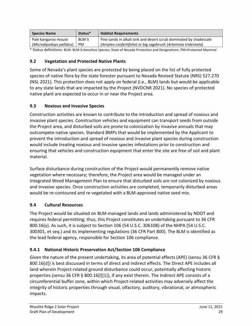
Species Name Status* Habitat Requirements Pale kangaroo mouse (Microdipodops pallidus)
BLM‐S PM
Fine sands in alkali sink and desert scrub dominated by shadescale (Atriplex confertifolia) or big sagebrush (Artemisia tridentata)
* Status definitions: BLM: BLM‐S=Sensitive Species; State of Nevada Protection and Designations: PM=Protected Mammal 9.2 Vegetation and Protected Native Plants
Some of Nevada’s plant species are protected by being placed on the list of fully protected species of native flora by the state forester pursuant to Nevada Revised Statute (NRS) 527.270 (NSL 2021). This protection does not apply on federal (i.e., BLM) lands but would be applicable to any state lands that are impacted by the Project (NVDCNR 2021). No species of protected native plant are expected to occur in or near the Project area. 9.3 Noxious and Invasive Species
Construction activities are known to contribute to the introduction and spread of noxious and invasive plant species. Construction vehicles and equipment can transport seeds from outside the Project area, and disturbed soils are prone to colonization by invasive annuals that may outcompete native species. Standard BMPs that would be implemented by the Applicant to prevent the introduction and spread of noxious and invasive plant species during construction would include treating noxious and invasive species infestations prior to construction and ensuring that vehicles and construction equipment that enter the site are free of soil and plant material. Surface disturbance during construction of the Project would permanently remove native vegetation where necessary; therefore, the Project area would be managed under an Integrated Weed Management Plan to ensure that disturbed soils are not colonized by noxious and invasive species. Once construction activities are completed, temporarily disturbed areas would be re‐contoured and re‐vegetated with a BLM‐approved native seed mix. 9.4 Cultural Resources
The Project would be situated on BLM‐managed lands and lands administered by NDOT and requires federal permitting; thus, this Project constitutes an undertaking pursuant to 36 CFR 800.16(y). As such, it is subject to Section 106 (54 U.S.C. 306108) of the NHPA (54 U.S.C. 300301, et seq.) and its implementing regulations (36 CFR Part 800). The BLM is identified as the lead federal agency, responsible for Section 106 compliance. 9.4.1 National Historic Preservation Act/Section 106 Compliance Given the nature of the present undertaking, its area of potential effects (APE) (sensu 36 CFR § 800.16[d]) is best discussed in terms of direct and indirect effects. The Direct APE includes all land wherein Project‐related ground disturbance could occur, potentially affecting historic properties (sensu 36 CFR § 800.16[l][1]), if any exist therein. The Indirect APE consists of a circumferential buffer zone, within which Project‐related activities may adversely affect the integrity of historic properties through visual, olfactory, auditory, vibrational, or atmospheric impacts.

Rhyolite Ridge 2 Solar Project June 11, 2021 Draft Plan of Development 30
A preliminary inquiry through the Nevada Cultural Resource Information System (NVCRIS) shows that less than 1 percent of the Project has had previous survey, with at least one resource being identified. No historic General Land Office (GLO) maps are available for the area. The historic topographic map from 1898 shows one dirt roads is present, suggesting it is an unrecorded Historic‐era resources with the potential for secondary historic debris scatters (USGS 2021a). The 1963 historic topo maps shows the area much as it appears today with the current road configuration (USGS 2021b‐c). There are no current mining operations within the Project area, the closest being the Blanco Mine approximately 2 miles northwest (USGS 2021d). Cultural resource information maintained by the BLM may not have been represented in the databases checked. A visit to the BLM TFO is required to confirm the apparent lack of survey. One survey was identified for the lands administered by NDOT. Given this information, there is a potential for prehistoric resources within the Project area, and potential for historic resources outside the historic map objects mentioned above. An Inadvertent Discovery Plan would need to be created and followed in order to protect any buried resources that may be inadvertently disturbed by Project work. Although the Project’s Indirect APE has yet to be defined, several archaeological sites have been recorded in the immediate area. At least some of these are likely to fall within the Indirect APE. Prior to any studies commencing, confirmation of the spatial extent of assessment, based on the Project’s construction footprint, advance warning signage, stockpiling locations, routes of access, and staging areas, would be necessary. This would include assisting the BLM with defining the Indirect APE. Additional background research would be undertaken to confirm previous surveys and known sites. Sources would include NVCRIS records, BLM field office files, the National Register Information System, GLO archives, historic topographic maps, historic aerial imagery, and other sources. A Class III survey would be required and would involve qualified, permitted archaeologists who are familiar with the area’s archaeology and descendant communities. The Class III survey would serve to identify resources within the APE that are listed or eligible for the National Register of Historic Places (NRHP). Such resources are referred to as historic properties. This Class III survey report will be prepared to current BLM Guidelines and Standards for Archaeological Inventory (BLM 2021). Archaeologists who meet or exceed the United States Secretary of the Interior’s professional qualifications and are permitted by the Nevada BLM would determine whether any historic properties within the Project area are likely to be adversely affected by the Project’s scope of work. The studies should ultimately result in an anticipated finding of Project effect and, if adverse effects are anticipated, make preliminary recommendations as to how those effects

Rhyolite Ridge 2 Solar Project June 11, 2021 Draft Plan of Development 31
could be avoided or mitigated. Depending on the number and type of resources, there may be changes to the Project design to avoid the resources. If resources cannot be avoided, then they will need to be formally evaluated for the NRHP, and testing and data recovery may be required in order mitigate effects. Any excavation on prehistoric resources will also likely require Native American monitoring. 9.4.2 Native American Concerns/Tribal Consultation The BLM has a unique government‐to government relationship with Native American Tribes. This relationship is founded on provisions of the United States Constitution, federal treaties, federal statutes, and Executive Orders that require the agency to consult, as part of federal undertakings, with Tribes who recognize an historical, spiritual, or religious connection with or interest in a particular place or region. The BLM’s government‐to‐government consultation with Tribes is performed in compliance with Secretarial Order No. 3317, which outlines the Department of the Interior’s policy on tribal consultation. Research indicates that the Paiute and Panamint may have interests in this area. 9.5 Lands and Realty
The 6,810‐acre solar facility is completely on BLM land. The Project falls within the BLM TFO. The gen‐tie line would require a BLM ROW up to approximately 2.21 miles (11,680 linear feet) in length and 250 feet wide (67.0 acres). The gen‐tie line would also cross the NDOT‐administered ROW for Highway 265 and necessitate an easement with NDOT for up to 100 feet (0.6 acres). The Project area does not fall within a designated Area of Critical Environmental Concern per the most up to date 2019 shapefile from the BLM (2019). The WWEC has had a Programmatic Environmental Impact Statement (PEIS) prepared pursuant to P.L. 109‐58, Section 368 (USDOE 2008). The PEIS was developed in accordance with he National Environmental Policy Act (NEPA) of 1969 and analyzed the environmental impacts of designating energy corridors on federal land in 11 western dates and incorporated those designations into relevant land use and resource management plans. Under the Proposed Action, the agencies would designate, through relevant land use and resource management plans, federal energy corridors incorporating existing, designated federal energy corridors and additional, newly designated energy corridors located on federal land. These energy corridors would comprise a comprehensive, coordinated network of preferred locations for future energy transport projects that could be developed to satisfy the demand for energy. The policies and Interagency Operating Procedures (IOPs) developed under the Section 368 Corridor Program would establish minimum requirements for management of individual energy transport projects. The proposed policies identify management objectives and address the administration of future energy transport development activities. The proposed IOPs identify

Rhyolite Ridge 2 Solar Project June 11, 2021 Draft Plan of Development 32
required management procedures that would be incorporated into project‐specific energy transport development proposals. In addition, the Proposed Action would amend 89 BLM, 37 Forest Service (FS), 3 National Park Service (NPS), and 4 Department of Defense (DOD) land use plans in the 11 western states. The proposed land use plan amendments involve the adoption of programmatic energy transport development policies and IOPs. 9.6 Air Quality/Climate Change/Greenhouse Gases
National Ambient Air Quality Standards (NAAQS) for pollutants considered harmful to public health and the environment are set by the Environmental Protection Agency (EPA). The six principal pollutants are carbon monoxide, lead, nitrogen dioxide, ozone, particulate matter (PM10 and PM2.5), and sulfur dioxide. Sources of PM10 and PM2.5 include the suspension of dust through ground‐disturbing activities, road dust from vehicles, and emissions from internal combustion engines. The EPA defines attainment areas as geographic areas that meet or exceed the NAAQS. Nonattainment areas refer to areas that do not meet this standard (EPA 2021). Maintenance areas are those that were once in nonattainment but now meet the current standards. The Project is located within a nonattainment area for PM2.5 and PM10. Esmeralda County, Nevada, does not appear to have an air quality department; air quality is overseen by NDEP. The permitting branches in the Bureau of Air Pollution Control issues air quality operating permits to stationary and temporary mobile sources that emit regulated pollutants to ensure that these emissions do not harm public health or cause significant deterioration in areas that presently have clean air. This is achieved by stipulating specific permit conditions designed to limit the number of pollutants that sources may emit into the air as a regular part of their business processes. Any process/activity that is an emission source requires an air quality permit. NRS 445B.155 defines an emission source as "any property, real or personal, which directly emits or may emit any air contaminant." NRS 445B.110 defines an "air contaminant" as "any substance discharged into the atmosphere except water vapor and droplets." In other words, a permit will not be required if activities, equipment, or storage containers do not cause emissions other than steam or water particles. The following thresholds are a guide to the various air quality permit types:
• Class I—Typically for facilities that emit more than 100 tons per year for any one regulated pollutant or emit more than 25 tons per year total Hazardous Air Pollutant (HAP) or emit more than 10 tons per year of any one HAP or is a Prevention of Significant Deterioration source or major Maximum Achievable Control Technology source
• Class II—Typically for facilities that emit less than 100 tons per year for any one regulated pollutant and emit less than 25 tons per year total HAP and emit less than 10 tons per year of any one HAP
• SAD—Surface area disturbance of greater than 5 acres

Rhyolite Ridge 2 Solar Project June 11, 2021 Draft Plan of Development 33
• General/Change of Location—Temporary portable equipment for road and highway construction at a location for less than 12 months
Additional information regarding NDEP air quality permitting can be obtained from the NDEP website (NDEP 2021a). 9.7 Noise
There are no sensitive noise receptors within the Project area, and there does not appear to be any adjacent to the Project area. The Project area is positioned at the western end of the Big Smoky Valley, which is sparsely populated. The nearest residences appear to be several miles to the southeast. Construction activities would produce a short‐term increase in noise at the site boundary over the existing ambient noise levels. 9.8 Visual Resources
The term “visual resources” refers to the composite of basic terrain, geologic, and hydrologic features; vegetative patterns; and built features that influence the visual appeal of a landscape. Visual impacts are defined as the change to the visual environment resulting from the introduction of modifications to the landscape. The Project area lies within the Basin and Range physiographic province, which is characterized by steep, narrow, isolated mountain ranges—generally on a north‐south axis—separated by wide, flat, sediment‐filled valleys or basins (ONE 2021). The Project area is located on the gently sloping foothills on the western end of the Big Smoky Valley in the Tonopah Basin where the ground consists primarily of tan, khaki, and gray sands and gravel incised by several small drainages that run off the landforms to the east into the former lake that occupied the lower extent of the Big Smoky Valley basin. The vegetation is made up predominantly of low‐lying alkali desert scrub. Several seasonal drainages cross the Project area; however, they do not appear to be persistent enough to support a dedicated riparian vegetation community. The notable natural features within and surrounding the Project area are the Monte Cristo Range mountains north of Big Smokey Valley, the Wepah Hills to the southeast, and the Silver Peak range immediately to the west. These three ranges drain into the western end of the Big Smoky Valley, which stretches east and northeast for over 45 miles. Numerous alluvial fans, piedmonts, ballenas, and sand dunes lead down to the former lakebed several miles northeast of the Project area. It appears as if two former lakeshore levels would have passed through the Project area as well, though they may have been buried in the Project area itself. The surrounding landforms and mountain ranges are rugged, with hard angular shapes consisting of dark grays, blacks, browns, and tans. The built environment consists of Highway 265 running roughly north/south immediately east of the Project area, with a few scattered mining areas in and around the Project area. The nearest towns are Coaldale, approximately 6 miles northwest, and Blair, approximately 12 miles south/southeast.

Rhyolite Ridge 2 Solar Project June 11, 2021 Draft Plan of Development 34
The BLM uses the Visual Resource Management (VRM) System to classify and manage visual resources on lands under its jurisdiction. The VRM System involves inventorying scenic values, establishing management objectives for those values through the resource management planning process, and then evaluating proposed activities to determine whether they conform to the management objectives (BLM 1984). The BLM’s VRM System incorporates scenic quality, viewer sensitivity, and visual distance zones to identify overall visual resource inventory classes. These classes (I, II, III, and IV) represent the relative value of the existing visual landscape as well as the visual resource baseline from which to measure impacts that a proposed Project may have on these values. In its planning process, the BLM weighs visual and competing resource values to allocate the VRM classes with associated management class objectives for a given area’s visual setting. There are approximately 6,810 acres of lands administered by the BLM within the Project area, none of which have been previously examined per the most up to date VRM shapefile (BLM 2020). Potential visual impacts from the Project would depend on an analysis of visual dominance, scale, and contrast to determine the degree that the Project would attract attention and to assess the relative change in character as compared to the existing characteristic landscape and its inherent scenic quality. The amount of visual contrast created is directly related to the amount of attention that is drawn to a feature in the landscape and, consequently, the visual impacts. 9.9 Water Resources
The Project falls within the Tonopah watershed region. Based on data from the National Hydrography Dataset and the State of Nevada Division of Water, the Project area does not cross any perennial or intermittent waters but does cross several miles of unnamed ephemeral waters, all on BLM land. The Project area is not located within 0.25 mile of any listed impaired water on NDEP’s 2016 to 2018 Water Quality Integrated Report (NDEP 2021b). Additionally, the entire Project area is outside the 100‐year floodplain. 9.10 Clean Water Act/Section 404 Compliance
USACE is responsible for regulating compliance with Section 404 of the CWA concerning potential impacts to WOUS. USACE regulates activities that discharge dredged or fill materials into jurisdictional WOUS and issues permits for these discharges under Section 404 of the CWA. There are no WOUS within the Project area. 9.11 Clean Water Act/Section 402 Compliance
The NEDP is the permitting authority for CWA Section 402 Stormwater permitting and regulation for discharges that enter Nevada “surface waters” and are associated with construction activities that will ultimately disturb one or more acres of land in Nevada. Coverage under the Section 402 Stormwater permitting, as well as any of the Construction General Permit (CGP) requirements (e.g., SWPPP, associated stormwater control measures,

Rhyolite Ridge 2 Solar Project June 11, 2021 Draft Plan of Development 35
stormwater inspections of a routine frequency), would not be required for this Project, as potential stormwater discharges would not have the capability to reach surface waters as regulated by NEDP and CGP. 9.12 Ground Water
The Project would require up to 600 AF of water during the approximately 18‐month construction period and up to approximately 100 AFY for O&M activities. Early coordination with NEDP, specifically the Bureau of Safe Drinking Water, would assist in determining the appropriate permit needed if the construction of a groundwater well is necessary. Currently the proposed Project area is between the state‐endorsed Tonopah and Silver Peak wellhead protection plans. 9.13 Wilderness Characteristics
The Project area does not fall on any lands with wilderness characteristics or designated wilderness areas. 9.14 Hazardous Materials
A preliminary desktop review using available online resources was conducted for the Project area and vicinity. There are no brownfields near the Project area per NDEP. There are no superfund sites in Esmeralda County per the EPA. There does not appear to be any known hazardous waste/material sites within the vicinity of the Project area. 9.15 Rangeland Resources
The Project area falls within the Silver Peak range allotment (NV00097). The Project area extends across 6,810 acres of this Silver Peak Range allotment, which is 2.4 percent of the total allotment acreage (277,092 acres). This allotment is year‐round, but no animal unit months (AUMs) are able to be identified at this time. The gen‐tie line crosses into the Sheep Mountain range allotment. The AUM is the carrying capacity of the land to support grazing animals such as horses, burros, cattle, and sheep (NHABRMC 2021). The AUM is calculated based on species, weight, and presence of a juvenile. BLM generally considers a “wild” horse one year of age or older as one animal unit (AU), and one burro one year of age or older as 0.5 AU. An AU is commonly defined as 1,000 pounds of body weight, and an AUM is the amount of forage needed to sustain an AU for one month. The AUM for a Herd Management Area (HMA) is used to determine the Appropriate Management Levels (AML) for the area. The Project area also falls within the Silver Peak HMA. This HMA consists of 239,801 acres of BLM land and another 2,661 acres of private and other lands. The AML is 4 to 6 wild burros. 9.16 Farmlands (Prime or Unique) and Soil Resources
Rhyolite Ridge 2 Solar Project June 11, 2021 Draft Plan of Development 36
The Farmland Protection Policy Act (FPPA) is intended to minimize the impact of federal programs on the unnecessary and irreversible conversion of farmland to nonagricultural uses. For the purpose of FPPA, farmland includes prime farmland, unique farmland, and land of statewide or local importance. Farmland does not have to be currently used for cropland to be subject to FPPA requirements. It can also be forest land, pastureland, cropland, or other land, but not open water or urban developed land. Prime farmland is land that has the best combination of physical and chemical characteristics for producing food, feed, forage, fiber, and oilseed crops (USDA 2019). There are several soil types within the Project area per the Soil Survey Geographic database data (WSS 2021). These include:
• Unsel‐Belted Orphant association (not prime farmland, fan remnants with 2 to 8 percent slope)
• Unsel‐Wardenot‐Izo association (not prime farmland, fan remnants, with 2 to 8 percent slope)
• Yomba‐playas‐Youngston association (alkali) (not prime farmland, alluvial flats, with 0 to 2 percent slope)
• Terlco‐Roic‐Wardenot association (not prime farmland, fan remnants, with 2 to 8 percent slope)
• Zaba‐Gynelle association (not prime farmland, beach plains, with 2 to 8 percent slope) • Roic‐Wardenot‐Badland association (not prime farmland, hills, with 8 to 30 percent
slope) • Downeyville‐Pintwater‐Rock Outcrop association (not prime farmland, hills, with 8 to 30
percent slope) • Wardenot‐Izo association (not prime farmland, inset fans, with 2 to 8 percent slope)
None of the 6,810 acres are considered prime farmland. Due to lack of agricultural activities within the Project area, the land would not be considered irrigated. Therefore, none of the lands within the Project area would need to be evaluated by analyzed by Natural Resources Conservation Service for farmland impacts. There are no active mining activities within the Project area. However, the area has likely experienced limited mining interest, as prospect pits are depicted on historic topographic maps. A review of the USGS Mineral Resources Database (USGS 2021d) shows several prospect pits and trenches within the Project area, with a few small pits outside along Highway 265 and more to the southwest at higher elevations.

Rhyolite Ridge 2 Solar Project June 11, 2021 Draft Plan of Development 37
10.0 REFERENCES American National Standards Institute (ANSI). 2018. Tree, Shrub, and Other‐Woody Plant
Management—Standard Practices (Integrated Vegetation Management). ANSI A300 (Part 7)‐2018 Integrated Management Revision of ANSI A300 (Part 7)‐2012).
Bureau of Land Management (BLM). 1984. Visual Resource Management. Manual 8400.
Accessed April 14, 2021 from: https://www.blm.gov/sites/blm.gov/files/program_ recreation_visual%20resource%20management_quick%20link_BLM%20Manual%20Section%208400%20‐%20Visual%20Resource%20Management.pdf.
___________. 2007. National Invasive Species Information Management System Project
Development DD: 11/01/2007. Accessed April 14, 2021 from: https://www.blm.gov/ policy/im‐2007‐159.
___________. 2008a. Integrated Vegetation Management Handbook. H‐1740‐2 United States
Department of the Interior, Bureau of Land Management, Washington, D.C. Accessed April 14, 2021 from: https://www.blm.gov/sites/blm.gov/files/uploads/Media_Library_ BLM_Policy_Handbook_H‐1740‐2.pdf.
___________. 2008b. National Environmental Policy Act Handbook. H‐1790‐1. United States
Department of the Interior, Bureau of Land Management, Washington, D.C. Accessed April 14 from: https://www.ntc.blm.gov/krc/uploads/366/NEPAHandbook_H‐1790_508 .pdf.
___________. 2017. 2017 Final BLM Nevada Sensitive Species Status List. United States
Department of the Interior. November 22, 2017. ___________. 2019. BLM National Designated Areas of Critical Environmental Concern
Polygons. Released 2019. Accessed April 14, 2021 from: https://landscape.blm.gov/ geoportal/catalog/search/resource/details.page?uuid=%7BD775CBAC‐862F‐4F87‐B0BD‐1CB8759B8CF7%7D.
___________. 2020. Visual Resource Management shapefile. Accessed April 14, 2021 from:
https://www.blm.gov/services/geospatial/GISData/Nevada. ___________. 2021. Guidelines and Standards for Archaeological Inventory, Sixth Edition.
Accessed April 14, 2021 from: https://www.blm.gov/sites/blm.gov/files/documents/ files/Library_Nevada_GuidelinesandStandardsArchaeologicalInventorySixthEdition_1.pdf.
Esmeralda County Commissioners (ECC). 2011. Master Plan Esmeralda County, Nevada.
Accessed April 14, 2021 from: https://www.accessesmeralda.com/document_center/ Es__Co___Master_Plan_adopted_Dec__7__2011.pdf.

Rhyolite Ridge 2 Solar Project June 11, 2021 Draft Plan of Development 38
Environmental Protection Agency (EPA). 2021. Nonattainment Areas of Criteria Pollutants
(Green Book). Accessed April 14, 2021 from: https://www.epa.gov/green‐book. Miller, R. H. 2013. Integrated Vegetation Management, Second Edition. Special companion
publication to ANSI A300, Party 7. Utility Arborist Association Best Management Practices. International Society of Arboriculture, Champaign, Illinois.
National Horse and Burrow Rangeland Management Coalition (NHABRMC). 2021. Terms and
Definitions. Accessed April 14, 2021 from: http://www.wildhorserange.org/terms‐and‐definitions.html.
Nevada Department of Conservation and Natural Resources (NVDCNR). 2021. State of Nevada
Native Plant Laws. Accessed April 14, 2021 from: http://forestry.nv.gov/wp‐content/uploads/2009/03/cactus‐brochure.pdf.
Nevada Division of Environmental Protection (NDEP). 2021a. Permit Guidance. Accessed April
14, 2021 from: https://ndep.nv.gov/air/permitting/permit‐guidance. ___________. 2021b. Water Quality Integrated Report. Accessed April 14, 2021 from:
http://webgis.ndep.nv.gov/. Nevada Division of Natural Heritage (NDNH). 2021. At‐Risk Plant and Animal Tracking List.
Department of Conservation and Natural Resources. January 2021. Nevada State Legislature (NSL). 2021. Chapter 527—Protection and Preservation of Timbered
Lands, Trees, and Flora. Accessed April 14, 2021. Nevada Public Utilities Commission (NPUC). 2021. Potential Permits. Accessed April 21, 2021
from: https://puc.nv.gov/Utilities/Construction_Permits/Potential_Permits/ Online Nevada Encyclopedia (ONE). 2021. Nevada’s Physical Setting. Accessed April 14, 2021
from: https://www.onlinenevada.org/articles/nevadas‐physical‐setting. Schultz, K.A. 2016a. Terrestrial Ecological System: Inter‐Mountain Basins Greasewood Flat.
NatureServe Explorer. January 26, 2016. ___________. 2016b. Terrestrial Ecological System: Inter‐Mountain Basins Mat Saltbush
Shrubland. NatureServe Explorer. January 26, 2016. United States Department of Agriculture (USDA). 2019. Farmland Protection Policy Act.
Accessed April 14, 2021 from: https://www.nrcs.usda.gov/wps/portal/nrcs/main/ national/landuse/fppa/.
Rhyolite Ridge 2 Solar Project June 11, 2021 Draft Plan of Development 39
United States Department of Energy (USDOE). 2008. Programmatic Environmental Impact
Statement, Designation of Energy Corridors on Federal Land in 11 Western States (DOE/EIS‐0386). Volume 1: Summary and Main Text. Accessed April 21, 2021 from: https://corridoreis.anl.gov/eis/documents/fpeis/vol1/WWEC_FPEIS_FrontI.pdf
United States Fish and Wildlife Service (USFWS). 2020. October 1, 2020. National Wetlands
Inventory website. United States Department of the Interior, Fish and Wildlife Service, Washington, D.C., http://www.fws.gov/wetlands.
___________. 2021 April 14, 2021. Information, Planning and Conservation online screening
tool. United States Department of the Interior, Fish and Wildlife Service, Washington, D.C., https://ecos.fws.gov/ipac/.
United States Geologic Survey (USGS). 2011. Download GAP/LANDFIRE National Terrestrial
Ecosystems 2011 data. Accessed April 14, 2021 from: https://www.usgs.gov/core‐science‐systems/science‐analytics‐and‐synthesis/gap/science/land‐cover‐data‐download?qt‐science_center_objects=0#qt‐science_center_objects.
___________. 2021a. 1898 Silver Peak 60‐Minute Topographic Map. Accessed June 9, 2021
from https://ngmdb.usgs.gov/ht‐bin/tv_browse.pl?id=08f7e19c9cbf08a708dd7274d0ce82be
___________. 2021b. 1963 Goldfield 15‐Minute Topographic Map. Accessed June 9, 2021 from
https://ngmdb.usgs.gov/ht‐bin/tv_browse.pl?id=88a0f4ef693ca59dfa07c6425e2ef69b ___________. 2021c. 1963 Silver Peak 15‐Minute Topographic Map. Accessed June 9, 2021
from https://ngmdb.usgs.gov/ht‐bin/tv_browse.pl?id=75121b68bab4e6b6f7c16ff0611f1ffd
___________. 2021d. Mineral Resources Database Map. Accessed June 9, 2021 from:
https://mrdata.usgs.gov/general/map‐us.html. Web Soil Survey (WSS). 2021. Web Soil Survey Home. Accessed April 14, 2021 from:
https://websoilsurvey.sc.egov.usda.gov/App/HomePage.htm.

Rhyolite Ridge 2 Solar Project June 11, 2021 Draft Plan of Development Appendix A
APPENDIX A
LOCATION MAP

!!
!!
!!
!!
!
!
!
!
!
!
!
!
!
!
!
!
!
!
!
!
!
!
!
!
!
!
!
!
!
!
!
!
!
!
!
!
!
!
!
!
! ! !!
!!
!!
!!
!!
!!
!!
!!
!!
!!
!!
!!
!!
!!
!!
!!
!!
!
") ") ") ") ") ") ")")
")
")")
SR265
Project Location
336SP 8me LLCRhyolite Ridge 2
Legend
®0 7,500
Feet1:88,000
Date: 6/11/2021Projection: NAD_1983_UTM_Zone_11N
Esmeralda County
Proposed Esmeralda Substation! ! Proposed Greenlink 525kV Transmission Line
")
Proposed Overhead Transmission InterconnectionProposed Transmission Structure
West-Wide Energy CorridorProject BoundaryBLMProposed Substation

Rhyolite Ridge 2 Solar Project June 11, 2021 Draft Plan of Development Appendix B
APPENDIX B
PROJECT LAYOUT

Proposed O&M Building
Proposed Substation
State Highway 265
Proposed Laydown & Staging
Proposed Laydown & Staging
®
336SP 8me LLCRhyolite Ridge 2
0 2,000 4,000Feet
June 11, 2021 G:\Projects\Eight_Minute_Solar\Rhyolite_Ridge_2_project_Updated\Rhyolite_Ridge_2_layout.mxd
Site Layout
T01N R37E S013-014, 023-026, 036; T01N R38E S015, 016, 019-21, 029-033;T01S R38E S003-006, 009-014T01S R39E S007, 017-019Rhyolite Ridge NE QuadrangleNorth of Silver Peak QuadrangleRhyolite Ridge QuadrangleSilver Peak QuadrangleEsmeralda County, NV
1:50,000
Project Location
Proposed Transmission Structures")
Legend
Existing Roads Proposed Access Roads Proposed Underground MV Collectors Proposed Overhead Transmission Interconnection
! !
Proposed Greenlink 525kV Transmission Line
West-Wide Energy Corridor
Project AreaProposed Photovoltaic Array AreaProposed Battery Energy Storage System Proposed SubstationProposed Laydown and Staging Proposed O&M Building
Property Boundary Acreage 6,810 acresProposed On-Site Access Road Length 64,659 ftProposed Fence Length 138,653 ftSingle-Axis Tracker Unit Quantity 27,199BESS 33.32 acresProposed Substation 2.62 acresProposed O&M Building 0.09 acresProposed Underground MV Collectors 92,910ftProposed Overhead Transmission Interconnection 11,431 ftProposed Transmission Structures Count 11Inverter Count 250Proposed Laydown and Staging 11.56 acresInterconnection Voltage 525 kVAC Capacity 600 MW @ POIStructure NextrackerGround Coverage Ratio 0.31Module Capacity 540 WInverter Capacity 3800kW/4200kVA
Project Details


![La Hierba and Rhyolite LVU Facilities Seepage Analyses R3[1]](https://img.dokumen.tips/doc/110x75/577ce7c61a28abf10395bbfa/la-hierba-and-rhyolite-lvu-facilities-seepage-analyses-r31.jpg)

