Embed Size (px)
Citation preview
85264190214000 © SANYO 2006
In CanadaSANYO FISHER COMPANY SANYO Canada Inc.A DIVISION OF SANYO NORTH AMERICA CORPORATION 300 Applewood Crescent, Concord21605 Plummer Street Ontario, L4K 5C7, CanadaChatsworth, CA 91311 U.S.A.
ContentsPage
IMPORTANT!Please Read Before Starting .................................. 2
1. GENERAL .......................................................... 31-1. Tools Required for Installation (not supplied)1-2. Accessories Supplied with Unit1-3. Optional Copper Tubing Kit1-4. Type of Copper Tube and Insulation Material1-5. Additional Materials Required for Installation
2. INSTALLATION SITE SELECTION ................... 42-1. Indoor Unit2-2. Connecting Indoor Units2-3. Outdoor Unit2-4 Baffle Plate for the Outdoor Unit
(CLM models only)2-5. Outer Dimensions of Outdoor Unit2-6. Diagram of Outdoor Unit Installation
3. INSTALLATION PROCESS .............................. 133-1. Embedding the Tubing and Wiring3-2. Use of the Flaring Method3-3. Flaring Procedure with a Flare Tool3-4. Caution before Connecting Tubes Tightly3-5. Tubing Connections3-6. Insulation of Refrigerant Tubing3-7. Taping the Tubes3-8. Finishing the Installation
4. AIR PURGING................................................... 16� Air Purging with a Vacuum Pump (for Test Run)� Pump Down
5. WIRING INSTRUCTIONS ................................ 195-1. General Precautions on Wiring5-2. Recommended Wire Length and Diameter5-3. Wiring System Diagram5-4. How to Connect Wiring to the Terminal5-5. Wiring Instructions for the Outdoor Unit
6. TEST RUN ......................................................... 23
7. CONNECTING A HOME AUTOMATIONDEVICE ............................................................. 24
8. INSTALLATION CHECK SHEET ...................... 24
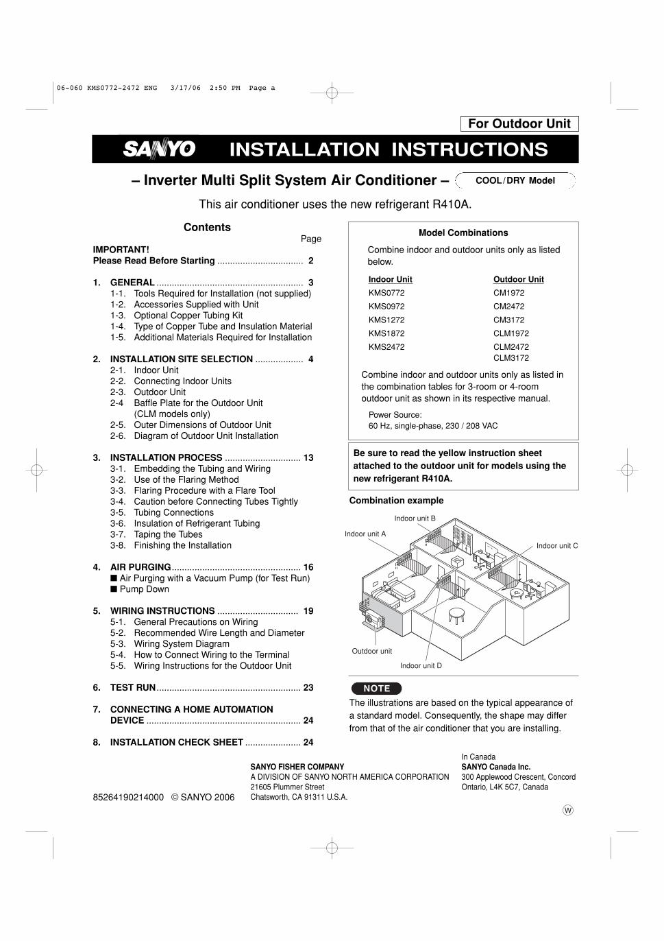
INSTALLATION INSTRUCTIONS
Model Combinations
Combine indoor and outdoor units only as listedbelow.
Indoor Unit Outdoor Unit
KMS0772 CM1972
KMS0972 CM2472
KMS1272 CM3172
KMS1872 CLM1972
KMS2472 CLM2472CLM3172
Combine indoor and outdoor units only as listed inthe combination tables for 3-room or 4-room outdoor unit as shown in its respective manual.
Power Source:60 Hz, single-phase, 230 / 208 VAC
– Inverter Multi Split System Air Conditioner – COOL/DRY Model
This air conditioner uses the new refrigerant R410A.
Be sure to read the yellow instruction sheetattached to the outdoor unit for models using thenew refrigerant R410A.
The illustrations are based on the typical appearance ofa standard model. Consequently, the shape may differfrom that of the air conditioner that you are installing.
NOTE
Indoor unit A
Indoor unit B
Indoor unit C
Indoor unit D
Outdoor unit
Combination example
For Outdoor Unit
06-060 KMS0772-2472 ENG 3/17/06 2:50 PM Page a
2
IMPORTANT! Please Read Before Starting
This air conditioning system meets strict safety and operatingstandards. As the installer or service person, it is an importantpart of your job to install or service the system so it operatessafely and efficiently.
For safe installation and trouble-free operation, youmust:� Carefully read this instruction booklet before beginning.� Follow each installation or repair step exactly as shown.� Observe all local, state, and national electrical codes.� Pay close attention to all warning and caution notices
given in this manual.This symbol refers to a hazardor unsafe practice which canresult in severe personal injuryor death.
This symbol refers to a hazardor unsafe practice which canresult in personal injury or prod-uct or property damage.
If Necessary, Get HelpThese instructions are all you need for most installationsites and maintenance conditions. If you require help for aspecial problem, contact our sales/service outlet or yourcertified dealer for additional instructions.
In Case of Improper InstallationThe manufacturer shall in no way be responsible for improp-er installation or maintenance service, including failure tofollow the instructions in this document.
SPECIAL PRECAUTIONS
When Wiring
ELECTRICAL SHOCK CAN CAUSE SEVEREPERSONAL INJURY OR DEATH. ONLY AQUALIFIED, EXPERIENCED ELECTRICIANSHOULD ATTEMPT TO WIRE THIS SYSTEM.
• Do not supply power to the unit until all wiring and tubingare completed or reconnected and checked.
• Highly dangerous electrical voltages are used in thissystem. Carefully refer to the wiring diagram and theseinstructions when wiring. Improper connections andinadequate grounding can cause accidental injury ordeath.
• Ground the unit following local electrical codes.• Connect all wiring tightly. Loose wiring may cause over-
heating at connection points and a possible fire hazard.
When Transporting
Be careful when picking up and moving the indoor and out-door units. Get a partner to help, and bend your knees whenlifting to reduce strain on your back. Sharp edges or thin alu-minum fins on the air conditioner can cut your fingers.
When Installing…
…In a Ceiling or Wall
Make sure the ceiling/wall is strong enough to hold theunit’s weight. It may be necessary to construct a strongwood or metal frame to provide added support.
…In a Room
Properly insulate any tubing run inside a room to prevent“sweating” that can cause dripping and water damage towalls and floors.
…In Moist or Uneven Locations
Use a raised concrete pad or concrete blocks to provide asolid, level foundation for the outdoor unit. This preventswater damage and abnormal vibration.
…In an Area with High Winds
Securely anchor the outdoor unit down with bolts and ametal frame. Provide a suitable air baffle.
…In a Snowy Area (for Heat Pump-type Systems)
Install the outdoor unit on a raised platform that is higherthan drifting snow. Provide snow vents.
When Connecting Refrigerant Tubing
• Use the flare method for connecting tubing.
• Apply refrigerant lubricant to the matching surfaces ofthe flare and union tubes before connecting them, thentighten the nut with a torque wrench for a leak-freeconnection.
• Check carefully for leaks before starting the test run.
When Servicing
• Turn the power OFF at the main power box (mains) beforeopening the unit to check or repair electrical parts andwiring.
• Keep your fingers and clothing away from any movingparts.
• Clean up the site after you finish, remembering to checkthat no metal scraps or bits of wiring have been left insidethe unit being serviced.
Others
• Ventilate any enclosed areas when installing or testingthe refrigeration system. Escaped refrigerant gas, oncontact with fire or heat, can produce dangerouslytoxic gas.
• Confirm upon completing installation that no refrigerantgas is leaking. If escaped gas comes in contact with astove, gas water heater, electric room heater or other heatsource, it can produce dangerously toxic gas.
• Do not install only a single indoor unit.
WARNING
WARNING
CAUTION
CAUTION
06-060 KMS0772-2472 ENG 3/17/06 2:50 PM Page 2
3
1. General
This booklet briefly outlines where and how to install theair conditioning system. Please read over the entire setof instructions for the indoor and outdoor units and makesure all accessory parts listed are with the system beforebeginning. If the electric wiring diagram does not appearin this manual, please check for the diagram on theindoor unit.
1-1. Tools Required for Installation (not supplied)1. Standard screwdriver2. Phillips head screwdriver3. Knife or wire stripper4. Tape measure
5. Carpenter’s level6. Sabre saw or key hole saw7. Hacksaw8. Core bits9. Hammer
10. Drill11. Tube cutter12. Tube flaring tool13. Torque wrench14. Adjustable wrench15. Reamer (for deburring)16. Vacuum pump (For R410A)17. Manifold valve
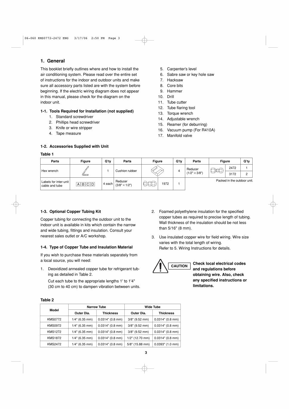
1-2. Accessories Supplied with Unit
Table 1
1-3. Optional Copper Tubing Kit
Copper tubing for connecting the outdoor unit to theindoor unit is available in kits which contain the narrowand wide tubing, fittings and insulation. Consult yournearest sales outlet or A/C workshop.
1-4. Type of Copper Tube and Insulation Material
If you wish to purchase these materials separately froma local source, you will need:
1. Deoxidized annealed copper tube for refrigerant tub-ing as detailed in Table 2.
Cut each tube to the appropriate lengths 1' to 1'4"(30 cm to 40 cm) to dampen vibration between units.
Table 2
2. Foamed polyethylene insulation for the specifiedcopper tubes as required to precise length of tubing.Wall thickness of the insulation should be not lessthan 5/16" (8 mm).
3. Use insulated copper wire for field wiring. Wire sizevaries with the total length of wiring. Refer to 5. Wiring Instructions for details.
Labels for inter-unitcable and tube
Reducer(3/8" 1/2") 1
Packed in the outdoor unit.
1
4 each
Hex wrench Cushion rubber 4
Parts Figure Q’ty Parts Figure Q’ty Parts Figure Q’ty
1972
2472
3172 2
1
A B C D
Reducer(1/2" 3/8")
CAUTIONCheck local electrical codesand regulations beforeobtaining wire. Also, checkany specified instructions orlimitations.
ModelNarrow Tube Wide Tube
Outer Dia. Thickness Outer Dia. Thickness
KMS0772 1/4" (6.35 mm) 0.0314" (0.8 mm) 3/8" (9.52 mm) 0.0314" (0.8 mm)
KMS0972 1/4" (6.35 mm) 0.0314" (0.8 mm) 3/8" (9.52 mm) 0.0314" (0.8 mm)
KMS1272 1/4" (6.35 mm) 0.0314" (0.8 mm) 3/8" (9.52 mm) 0.0314" (0.8 mm)
KMS1872 1/4" (6.35 mm) 0.0314" (0.8 mm) 1/2" (12.70 mm) 0.0314" (0.8 mm)
KMS2472 1/4" (6.35 mm) 0.0314" (0.8 mm) 5/8" (15.88 mm) 0.0393" (1.0 mm)
06-060 KMS0772-2472 ENG 3/17/06 2:50 PM Page 3
4
1-5. Additional Materials Required for Installation
1. Refrigeration (armored) tape2. Insulated staples or clamps for connecting wire
(See local codes)3. Putty4. Refrigeration lubricant5. Clamps or saddles to secure refrigerant tubing
2. Installation Site Selection
2-1. Indoor Unit
AVOID:
� direct sunlight.
� nearby heat sources that may affect performance of theunit.
� areas where leakage of flammable gas may be expected.
� placing or allowing any obstructions near the A/C inlet oroutlet.
� installing in rooms that contain instant-on (rapid-start) fluorescent lamps. (These may prevent the A/C from receiving signals.)
� places where large amounts of oil mist exist.
� installing in locations where there are devices that generate high-frequency emissions.
DO:
� select an appropriate position from which every corner ofthe room can be uniformly cooled. (High on a wall is best.)
� select a location that will hold the weight of the unit.
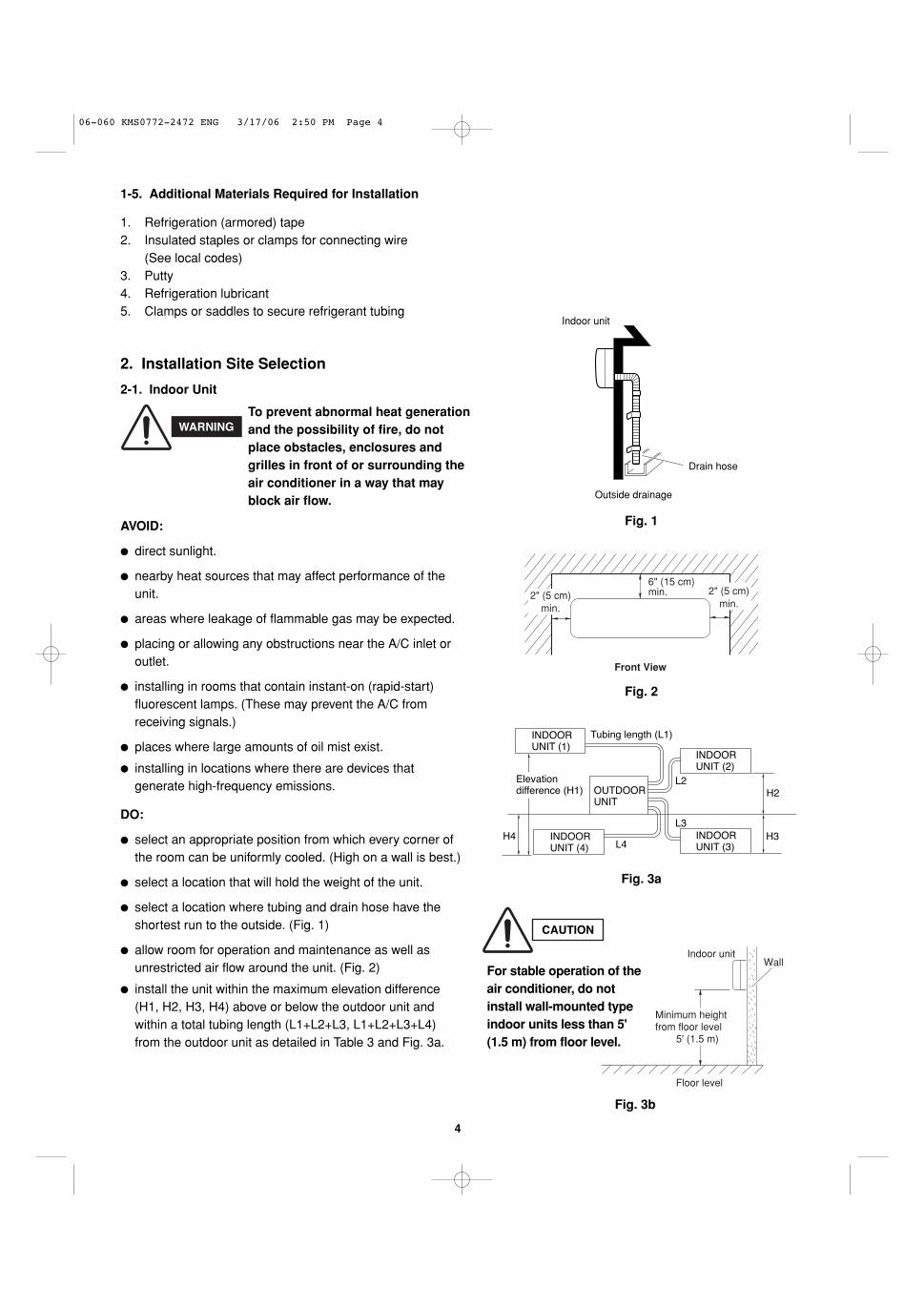
� select a location where tubing and drain hose have theshortest run to the outside. (Fig. 1)
� allow room for operation and maintenance as well as unrestricted air flow around the unit. (Fig. 2)
� install the unit within the maximum elevation difference(H1, H2, H3, H4) above or below the outdoor unit andwithin a total tubing length (L1+L2+L3, L1+L2+L3+L4)from the outdoor unit as detailed in Table 3 and Fig. 3a.
Drain hose
Indoor unit
Outside drainage
Fig. 1
2" (5 cm)min.
6" (15 cm)min.
Front View
2" (5 cm)min.
Fig. 2
INDOORUNIT (1)
INDOORUNIT (4)
INDOORUNIT (3)
INDOORUNIT (2)
Tubing length (L1)
L2
L3
L4
H2
H3H4
OUTDOORUNIT
Elevationdifference (H1)
Fig. 3a
WARNINGTo prevent abnormal heat generationand the possibility of fire, do notplace obstacles, enclosures andgrilles in front of or surrounding theair conditioner in a way that mayblock air flow.
Indoor unit
Floor level
Wall
Minimum height from floor level
5' (1.5 m)
Fig. 3b
For stable operation of theair conditioner, do notinstall wall-mounted typeindoor units less than 5'(1.5 m) from floor level.
CAUTION
06-060 KMS0772-2472 ENG 3/17/06 2:50 PM Page 4
5
� Install the indoor unit more than 3.3' (1 m) away from anyantenna or power lines or connecting wires used for tele-vision, radio, telephone, security system, or intercom.Electrical noise from any of these sources may affectoperation.
� install in a sturdy manner to avoid increased operatingnoise.
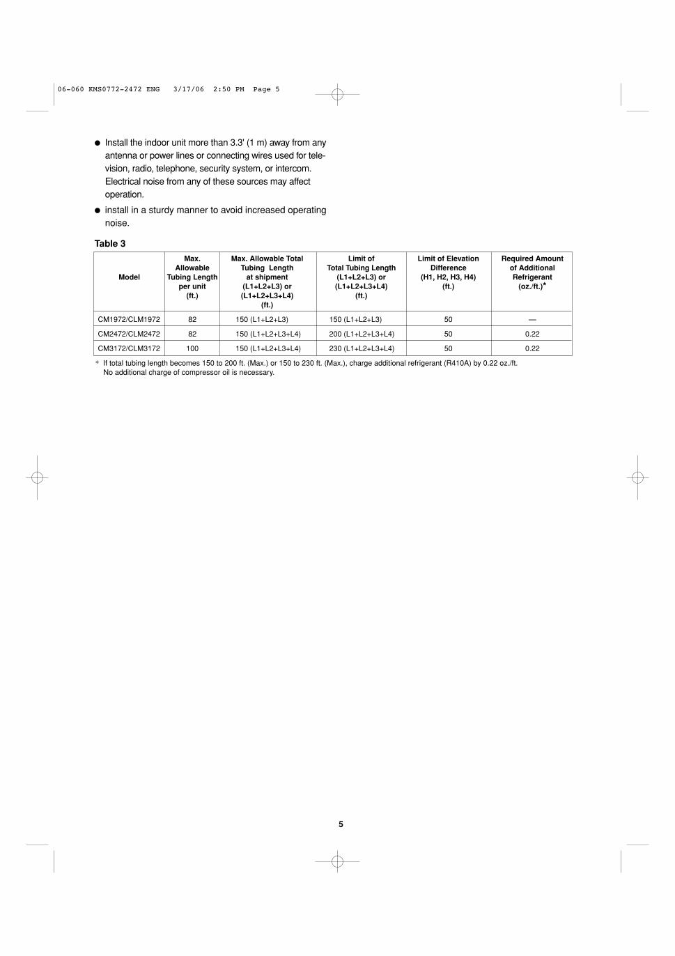
Table 3
* If total tubing length becomes 150 to 200 ft. (Max.) or 150 to 230 ft. (Max.), charge additional refrigerant (R410A) by 0.22 oz./ft. No additional charge of compressor oil is necessary.
Max. Max. Allowable Total Limit of Limit of Elevation Required AmountAllowable Tubing Length Total Tubing Length Difference of Additional
Model Tubing Length at shipment (L1+L2+L3) or (H1, H2, H3, H4) Refrigerantper unit (L1+L2+L3) or (L1+L2+L3+L4) (ft.) (oz./ft.)*
(ft.) (L1+L2+L3+L4) (ft.)(ft.)
CM1972/CLM1972 82 150 (L1+L2+L3) 150 (L1+L2+L3) 50 —
CM2472/CLM2472 82 150 (L1+L2+L3+L4) 200 (L1+L2+L3+L4) 50 0.22
CM3172/CLM3172 100 150 (L1+L2+L3+L4) 230 (L1+L2+L3+L4) 50 0.22
06-060 KMS0772-2472 ENG 3/17/06 2:50 PM Page 5
6
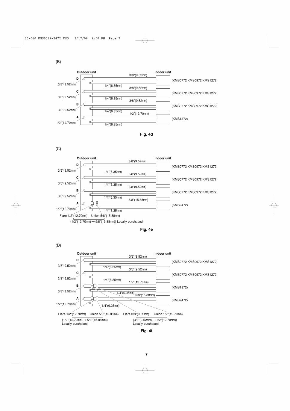
(B)
Fig. 4b
Union 1/2"(12.70mm)
1/2"(12.70mm)
Flare 3/8"(9.52mm)
A joint for connecting tubes ofdifferent sizes(3/8"(9.52mm) 1/2"(12.70mm)) Supplied Reducer
1/4"(6.35mm)
1/4"(6.35mm)
1/4"(6.35mm)
C
B
A
Outdoor unit Indoor unit
(KMS0772,KMS0972,KMS1272)
(KMS0772,KMS0972,KMS1272)
(KMS1872)
3/8"(9.52mm)
3/8"(9.52mm)
3/8"(9.52mm)
3/8"(9.52mm)
3/8"(9.52mm)
(A)
Fig. 4c
Union 3/8"(9.52mm)Flare 1/2"(12.70mm)
(1/2"(12.70mm) 3/8"(9.52mm)) Supplied Reducer
C
B
A
(KMS0772,KMS0972,KMS1272)
(KMS0772,KMS0972,KMS1272)
D
Outdoor unit Indoor unit
(KMS0772,KMS0972,KMS1272)
(KMS0772,KMS0972,KMS1272)1/2"(12.70mm)
3/8"(9.52mm)
3/8"(9.52mm)
3/8"(9.52mm)
3/8"(9.52mm)
3/8"(9.52mm)
3/8"(9.52mm)
3/8"(9.52mm)
1/4"(6.35mm)
1/4"(6.35mm)
1/4"(6.35mm)
1/4"(6.35mm)
(2) Connecting indoor unit for CM2472/CLM2472
(A)
Fig. 4a
3/8"(9.52mm)
3/8"(9.52mm)
1/4"(6.35mm)
1/4"(6.35mm)
1/4"(6.35mm)
3/8"(9.52mm)
3/8"(9.52mm)3/8"(9.52mm)
3/8"(9.52mm)
C
B
A
Outdoor unit Indoor unit
(KMS0772,KMS0972,KMS1272)
(KMS0772,KMS0972,KMS1272)
(KMS0772,KMS0972,KMS1272)
2-2. Connecting Indoor Units
(1) Connecting indoor unit for CM1972/CLM1972
06-060 KMS0772-2472 ENG 3/17/06 2:50 PM Page 6
7
(B)
Fig. 4d
C
B
A
(KMS0772,KMS0972,KMS1272)
(KMS0772,KMS0972,KMS1272)
D
Outdoor unit Indoor unit
(KMS0772,KMS0972,KMS1272)
(KMS1872)1/2"(12.70mm)
1/2"(12.70mm)
3/8"(9.52mm)
3/8"(9.52mm)
3/8"(9.52mm)
3/8"(9.52mm)3/8"(9.52mm)
3/8"(9.52mm)
1/4"(6.35mm)
1/4"(6.35mm)
1/4"(6.35mm)
1/4"(6.35mm)
(D)
Fig. 4f
Union 5/8"(15.88mm)Flare 1/2"(12.70mm)
(1/2"(12.70mm) 5/8"(15.88mm))Locally purchased
C
B
A
(KMS1872)
(KMS0772,KMS0972,KMS1272)
D
Outdoor unit Indoor unit
(KMS0772,KMS0972,KMS1272)
(KMS2472)
Union 1/2"(12.70mm)Flare 3/8"(9.52mm)
(3/8"(9.52mm) 1/2"(12.70mm)) Locally purchased
1/2"(12.70mm)
1/2"(12.70mm)
5/8"(15.88mm)
3/8"(9.52mm)
3/8"(9.52mm)
3/8"(9.52mm)
3/8"(9.52mm)
3/8"(9.52mm)
1/4"(6.35mm)
1/4"(6.35mm)
1/4"(6.35mm)
1/4"(6.35mm)
(C)
Fig. 4e
Union 5/8"(15.88mm)Flare 1/2"(12.70mm)
(1/2"(12.70mm) 5/8"(15.88mm)) Locally purchased
C
B
A
(KMS0772,KMS0972,KMS1272)
(KMS0772,KMS0972,KMS1272)
D
Outdoor unit Indoor unit
(KMS0772,KMS0972,KMS1272)
(KMS2472)1/2"(12.70mm)
3/8"(9.52mm)
3/8"(9.52mm)
3/8"(9.52mm)
3/8"(9.52mm)
5/8"(15.88mm)
3/8"(9.52mm)
3/8"(9.52mm)
1/4"(6.35mm)
1/4"(6.35mm)
1/4"(6.35mm)
1/4"(6.35mm)
06-060 KMS0772-2472 ENG 3/17/06 2:50 PM Page 7
8
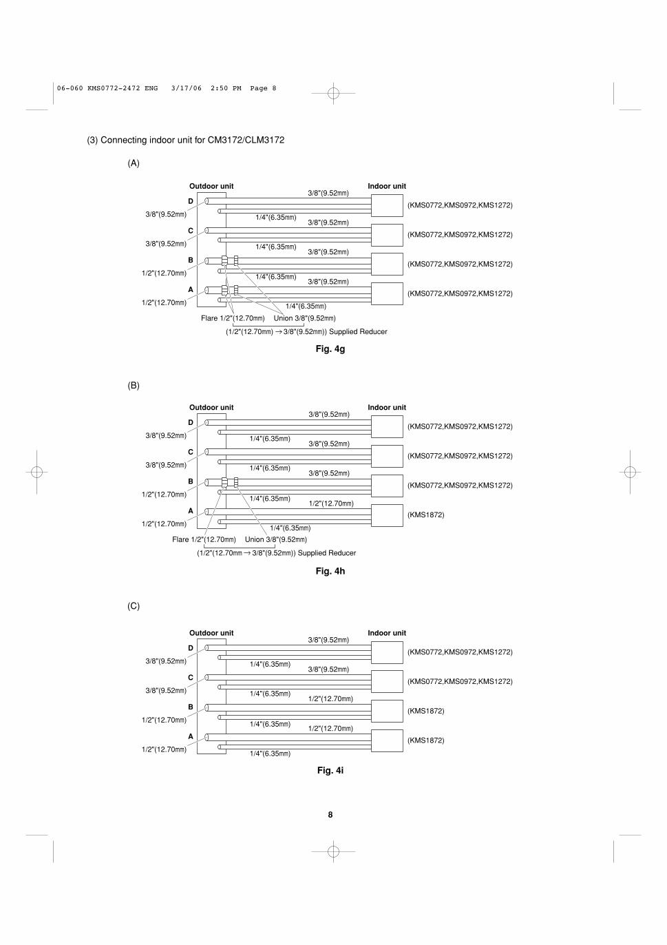
(A)
Fig. 4g
Union 3/8"(9.52mm)Flare 1/2"(12.70mm)
(1/2"(12.70mm) 3/8"(9.52mm)) Supplied Reducer
C
B
A
(KMS0772,KMS0972,KMS1272)
(KMS0772,KMS0972,KMS1272)
D
Outdoor unit Indoor unit
(KMS0772,KMS0972,KMS1272)
(KMS0772,KMS0972,KMS1272)
1/2"(12.70mm)
1/2"(12.70mm)
3/8"(9.52mm)
3/8"(9.52mm)
3/8"(9.52mm)
3/8"(9.52mm)
3/8"(9.52mm)
3/8"(9.52mm)
1/4"(6.35mm)
1/4"(6.35mm)
1/4"(6.35mm)
1/4"(6.35mm)
(3) Connecting indoor unit for CM3172/CLM3172
(B)
Fig. 4h
Union 3/8"(9.52mm)Flare 1/2"(12.70mm)
(1/2"(12.70mm 3/8"(9.52mm)) Supplied Reducer
C
B
A
(KMS0772,KMS0972,KMS1272)
(KMS0772,KMS0972,KMS1272)
D
Outdoor unit Indoor unit
(KMS0772,KMS0972,KMS1272)
(KMS1872)
1/2"(12.70mm)1/2"(12.70mm)
1/2"(12.70mm)
3/8"(9.52mm)
3/8"(9.52mm)
3/8"(9.52mm)
3/8"(9.52mm)3/8"(9.52mm)
1/4"(6.35mm)
1/4"(6.35mm)
1/4"(6.35mm)
1/4"(6.35mm)
(C)
Fig. 4i
C
B
A
(KMS1872)
(KMS0772,KMS0972,KMS1272)
D
Outdoor unit Indoor unit
(KMS0772,KMS0972,KMS1272)
(KMS1872)
1/2"(12.70mm)
1/2"(12.70mm)
3/8"(9.52mm)
3/8"(9.52mm)1/2"(12.70mm)
1/2"(12.70mm)
3/8"(9.52mm)
3/8"(9.52mm)1/4"(6.35mm)
1/4"(6.35mm)
1/4"(6.35mm)
1/4"(6.35mm)
06-060 KMS0772-2472 ENG 3/17/06 2:50 PM Page 8
9
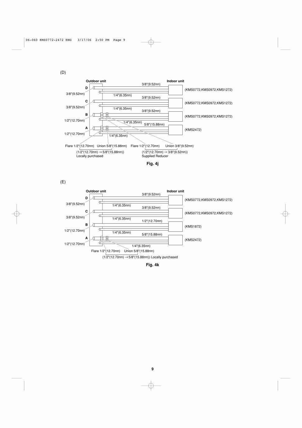
(D)
Fig. 4j
Union 5/8"(15.88mm)Flare 1/2"(12.70mm)
(1/2"(12.70mm) 5/8"(15.88mm))Locally purchased
C
B
A
(KMS0772,KMS0972,KMS1272)
(KMS0772,KMS0972,KMS1272)
D
Outdoor unit Indoor unit
(KMS0772,KMS0972,KMS1272)
(KMS2472)
Union 3/8"(9.52mm)Flare 1/2"(12.70mm)
(1/2"(12.70mm) 3/8"(9.52mm)) Supplied Reducer
1/2"(12.70mm)
1/2"(12.70mm)
5/8"(15.88mm)
3/8"(9.52mm)
3/8"(9.52mm)
3/8"(9.52mm)
3/8"(9.52mm)3/8"(9.52mm)
1/4"(6.35mm)
1/4"(6.35mm)
1/4"(6.35mm)
1/4"(6.35mm)
(E)
Fig. 4k
Union 5/8"(15.88mm)Flare 1/2"(12.70mm)
(1/2"(12.70mm) 5/8"(15.88mm)) Locally purchased
C
B
A
(KMS1872)
(KMS0772,KMS0972,KMS1272)
D
Outdoor unit Indoor unit
(KMS0772,KMS0972,KMS1272)
(KMS2472)
1/2"(12.70mm)
1/2"(12.70mm)
5/8"(15.88mm)
3/8"(9.52mm)
3/8"(9.52mm)1/2"(12.70mm)
3/8"(9.52mm)
3/8"(9.52mm)1/4"(6.35mm)
1/4"(6.35mm)
1/4"(6.35mm)
1/4"(6.35mm)
06-060 KMS0772-2472 ENG 3/17/06 2:50 PM Page 9
10
2-3. Outdoor Unit
AVOID:
� heat sources, exhaust fans, etc. (Fig. 5a)
� damp, humid or uneven locations.
DO:
� choose a place as cool as possible.
� choose a place that is well ventilated.
� allow enough room around the unit for air intake/exhaust and possible maintenance. (Fig. 5b)
� provide a solid base (level concrete pad, concreteblock, 6" ¥ 1'4" (15 ¥ 40 cm) beams or equal), a mini-mum of 6" (15 cm) above ground level to reducehumidity and protect the unit against possible waterdamage and decreased service life. (Figs. 5c and 5d)
� Install cushion rubber under unit’s feet to reducevibration and noise. (Fig. 5e)
� use lug bolts or equal to bolt down unit, reducingvibration and noise.
� Install in a location where no antenna of a televisionor radio exists within 10' (3 m).
2-4. Baffle Plate for the Outdoor Unit(CLM models only)
It is recommended to use baffle plates for modelsCLM1972, CLM2472 and CLM3172. The baffle platesare not normally required for the other models.
When the outdoor unit is installed in a position exposedto strong wind (like seasonal winds with low air tempera-ture in winter), baffle plates must be installed in front ofthe outdoor unit. (Fig. 5f)
This unit is designed so that the fan of the outdoor unitruns at low speed when the air conditioner is operated atlow outdoor air temperatures. When the outdoor unit isexposed to strong wind, the system pressure dropsbecause of the freeze protector.
NOTE
Outdoor unit
Hot airHeat source
Exhaust fanNO
Fig. 5a
Fig. 5b
Fig. 5d
Air intake Min. 8" (20 cm)
Air dischargeMin.4" (10 cm)
Min.1ʼ8" (50 cm)
ValvesideMin. 10"(25 cm)
Min.7' (2 m)
Min.7' (2 m)
Ground
Obs
tacl
e
Obstacle above
Air
disc
harg
e
Min. 8" (20 cm)Air intake
Air intake
Concreteor equal
About 6" (15 cm)
Min. 6" (15 cm)
Anchor bolts(4 pcs.)
About 16" (40 cm)
Fig. 5e
Cushion rubber
CAUTIONA solid base must not coverthe hole of the bottom plate.
Drain holes
Fig. 5c
Fig. 5f
Air discharge
12"
min Air
disc
harg
e
12" minBaffle plate
Baffle plate
06-060 KMS0772-2472 ENG 3/17/06 2:50 PM Page 10
11
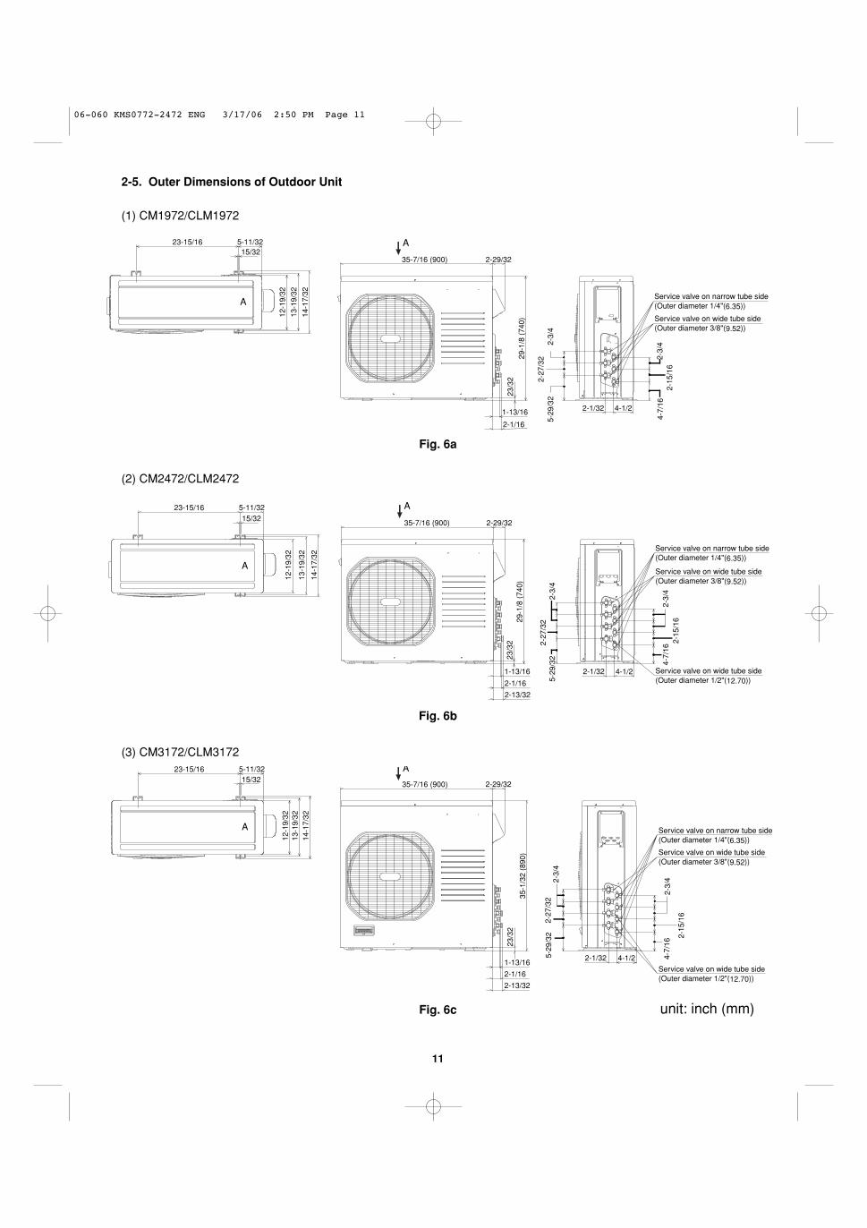
Fig. 6a
23-15/16 5-11/3215/32
35-7/16 (900)
13-1
9/32
12-1
9/32
14-1
7/32
2-29/32
29-1
/8 (
740)
23/3
2
1-13/16
2-1/16
5-29
/32
2-27
/32
2-3/
4
2-1/32
4-7/
162-
15/1
62-
3/4
4-1/2
A
Service valve on narrow tube side(Outer diameter 1/4"(6.35))
Service valve on wide tube side(Outer diameter 3/8"(9.52))
A
(1) CM1972/CLM1972
Fig. 6b
23-15/16 5-11/3215/32
12-1
9/32
13-1
9/32
14-1
7/32
35-7/16 (900)29
-1/8
(74
0)
2-1/16
1-13/16
2-29/32
2-13/32
A
4-1/22-1/32
5-29
/32
2-27
/32
2-3/
4
4-7/
162-
15/1
62-
3/4
Service valve on narrow tube side(Outer diameter 1/4"(6.35))
Service valve on wide tube side(Outer diameter 3/8"(9.52))
Service valve on wide tube side(Outer diameter 1/2"(12.70))
A
23/3
2
Fig. 6c
23-15/1615/32
12-1
9/32
13-1
9/32
14-1
7/32
5-11/32
35-7/16 (900)
23/3
2
35-1
/32
(890
)
2-29/32
2-1/16
1-13/16
2-13/32
4-1/22-1/32 4-7/
16
5-29
/32 2-
15/1
6
2-27
/32
2-3/
4
2-3/
4
A
Service valve on narrow tube side(Outer diameter 1/4"(6.35))
Service valve on wide tube side(Outer diameter 1/2"(12.70))
Service valve on wide tube side(Outer diameter 3/8"(9.52))
A
(2) CM2472/CLM2472
(3) CM3172/CLM3172
2-5. Outer Dimensions of Outdoor Unit
unit: inch (mm)
06-060 KMS0772-2472 ENG 3/17/06 2:50 PM Page 11
12
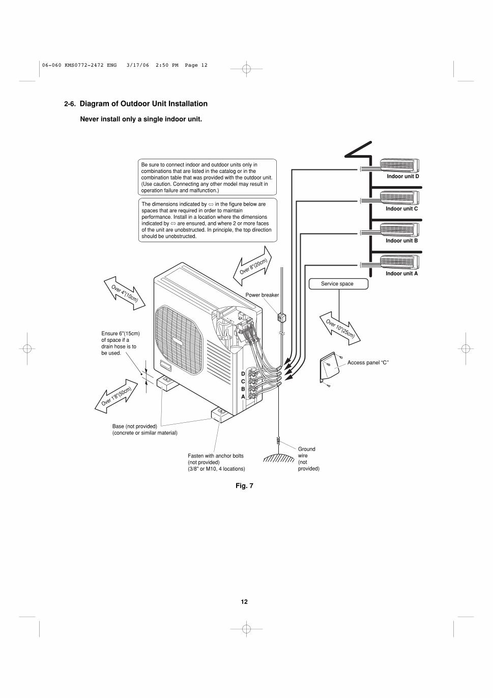
2-6. Diagram of Outdoor Unit Installation
Never install only a single indoor unit.
Be sure to connect indoor and outdoor units only in combinations that are listed in the catalog or in the combination table that was provided with the outdoor unit.(Use caution. Connecting any other model may result in operation failure and malfunction.)
The dimensions indicated by in the figure below are spaces that are required in order to maintain performance. Install in a location where the dimensions indicated by are ensured, and where 2 or more faces of the unit are unobstructed. In principle, the top direction should be unobstructed.
Indoor unit C
Indoor unit B
Indoor unit A
Indoor unit D
Service space
Power breaker
Groundwire(not provided)
Ensure 6"(15cm)of space if adrain hose is tobe used.
Base (not provided)(concrete or similar material)
Fasten with anchor bolts (not provided) (3/8" or M10, 4 locations)
ABCD
Access panel C
Over 10"(25cm)
Over 8"(20cm)
Over 4"(10cm)
Over 1'8"(50cm)
Fig. 7
06-060 KMS0772-2472 ENG 3/17/06 2:50 PM Page 12
13
3. Installation Process
3-1. Embedding the Tubing and Wiring
� Do not connect tubes to locations that are embedded.
� Be sure to bind refrigerant tubing and inter-unit cablestogether with vinyl tape.
� The power cable must be obtained on-site. (#12: Less than 85 ft.) # ... AWG (American Wire Gauge)
� Be sure to apply the provided labels to both ends ofthe inter-unit cables to prevent miswiring.
� Securely seal the end of embedded tubing with vinyltape in order to prevent dirt or moisture entry.
� In order to prevent insulation breakdown and groundfaults, do not allow the wire ends to contact rainwater,or be subject to dew condensation.
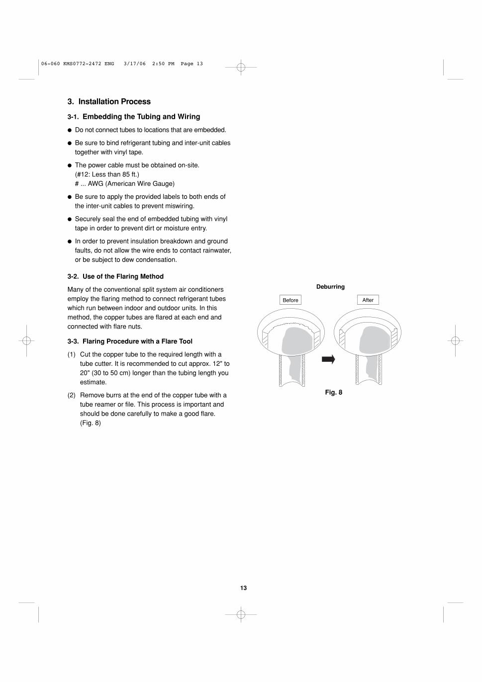
Deburring
Before After
Fig. 8
3-2. Use of the Flaring Method
Many of the conventional split system air conditionersemploy the flaring method to connect refrigerant tubeswhich run between indoor and outdoor units. In thismethod, the copper tubes are flared at each end andconnected with flare nuts.
3-3. Flaring Procedure with a Flare Tool
(1) Cut the copper tube to the required length with atube cutter. It is recommended to cut approx. 12" to20" (30 to 50 cm) longer than the tubing length youestimate.
(2) Remove burrs at the end of the copper tube with atube reamer or file. This process is important andshould be done carefully to make a good flare. (Fig. 8)
06-060 KMS0772-2472 ENG 3/17/06 2:50 PM Page 13

14
When reaming, hold the tube end downward and be sure thatno copper scraps fall into the tube. (Fig. 9)
(3) Remove the flare nut from the unit and be sure to mountit on the copper tube.
(4) Make a flare at the end of copper tube with a flare tool.*(Figs. 10 and 11)
(*Use “RIGID” or equivalent.)
A good flare should have the following characteristics:
� inside surface is glossy and smooth.
� edge is smooth.
� tapered sides are of uniform length.
3-4. Caution before Connecting Tubes Tightly
a) Be sure to apply a sealing cap or water-proof tape toprevent dust or water from getting into the tubes beforethey are used.
b) Be sure to apply refrigerant lubricant to the matching surfaces of the flare and union before connecting themtogether. This is effective for reducing gas leaks. (Fig. 12)
c) For proper connection, align the union tube and flaretube straight with each other, then screw in the flare nutlightly at first to obtain a smooth match. (Fig. 13)
3-5. Tubing Connections
a) Temporary connection:Screw in 3 – 5 rotations by hand. (Fig.14)
b) To fasten the flare nuts, apply specified torque as:
Table 4
NOTE
NOTE
Reamer
Coppertubing
Fig. 9
Flare tool
Flare nut
Copper tubing
Fig. 11
Fig. 10
Apply refrigerant lubricant here and here
Fig. 12
Flare nutUnion
Fig. 13
0 to 0.0196"(0 to 0.5 mm)
If the special R410A flare tool is used:
0.0472" (1.2 mm)
If the previous flare tool (clutch-type) is used:
Adjust so that the amount of tube protrusion is as shown in the figure.
Tube Dia. Tightening Torque
1/4" (6.35 mm) Approx. 120 – 160 lbs·in (140 – 180 kgf·cm)
3/8" (9.52 mm) Approx. 300 – 360 lbs·in (340 – 420 kgf·cm)
1/2" (12.70 mm) Approx. 430 – 540 lbs·in (490 – 610 kgf·cm)
5/8" (15.88 mm) Approx. 590 – 710 lbs·in (680 – 820 kgf·cm)
Apply the provided labels to the indoor and outdoor unit tubing connectors to prevent errors in connections.
Service valve on narrow tube side
Service valve on wide tube side
ABCD
Fig. 14
06-060 KMS0772-2472 ENG 3/17/06 2:50 PM Page 14

15
3-6. Insulation of Refrigerant Tubing
To prevent heat loss and wet floors due to dripping of con-densation, both tubes must be well insulated with aproper insulation material.The thickness of the insulation should be a minimum 5/16"(8 mm). (Fig. 17)
3-7. Taping the Tubes
(1) At this time, the 2 refrigerant tubes (and electrical wireif local codes permit) should be taped together witharmoring tape. The drain hose may also be includedand taped together as 1 bundle with the tubing.
(2) Wrap the armoring tape from the bottom of the outdoorunit to the top of the tubing where it enters the wall. Asyou wrap the tubing, overlap half of each previous tapeturn. (Fig. 18)
(3) Clamp the tubing bundle to wall, using 1 clamp approx.every 47" (120 cm).
Do not wind the armoring tape too tightly, since this willdecrease the heat insulation effect. Also, be sure the con-densation drain hose splits away from the bundle and dripsclear of the unit and the tubing.
3-8. Finishing the Installation
After finishing insulating and taping over the tubing, usesealing putty to seal off the hole in the wall to prevent rainand draft from entering. (Fig. 19)
NOTE
IMPORTANT
Indoor unit
Outdoor unit
Spanner
Torque wrench
Fig. 15
Insulation
Min. 5/16"(8 mm)
Thickness:min. 5/16"(8 mm)
Fig. 17
Fig. 18
Clamp
Insulated tubes
Apply putty here
Tubing
Fig. 19
CAUTION After a tube has been insulated,never try to bend it into a narrow curve, as this maycause the tube to break orcrack.
Insulation
Fig. 16
CAUTION Be sure to match refrigeranttubing and electric wiringbetween indoor and outdoorunits. For more details, refer to“Tubing Check Control” in theTechnical & Service Manual.
06-060 KMS0772-2472 ENG 3/17/06 2:50 PM Page 15
16
4. Air Purging
Air and moisture remaining in the refrigerant system haveundesirable effects as indicated below. Therefore, theymust be purged completely.
� pressure in the system rises
� operating current rises
� cooling efficiency drops
� moisture in the air may freeze and block capillary tubing
� water may lead to corrosion of parts in the refrigerantsystem
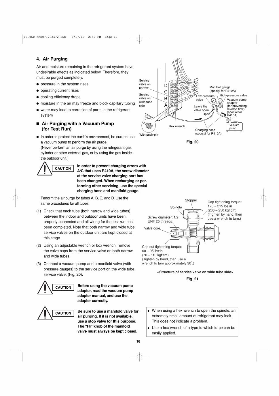
� Air Purging with a Vacuum Pump (for Test Run)
� In order to protect the earth’s environment, be sure to usea vacuum pump to perform the air purge.(Never perform an air purge by using the refrigerant gascylinder or other external gas, or by using the gas insidethe outdoor unit.)
Perform the air purge for tubes A, B, C, and D. Use thesame procedures for all tubes.
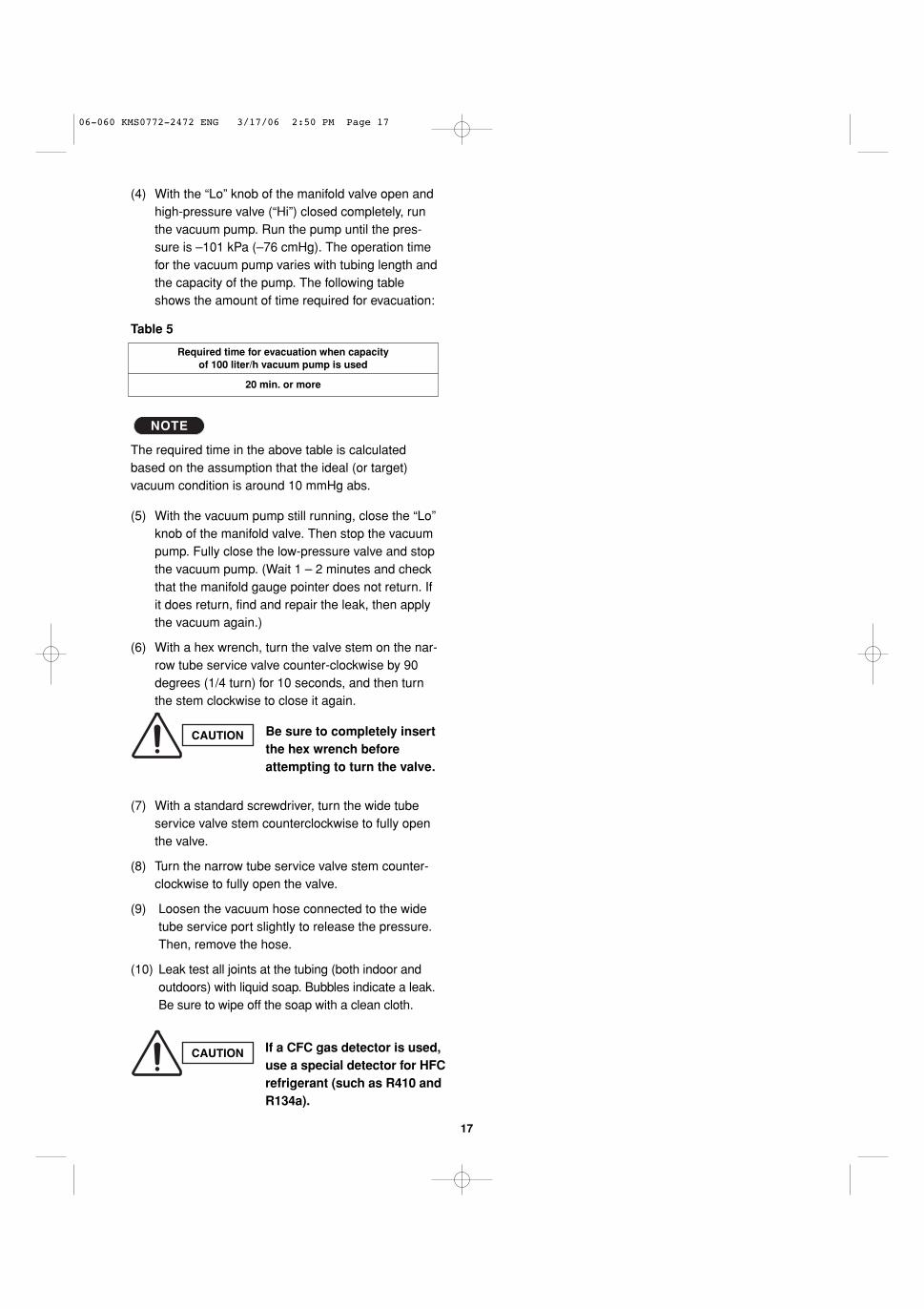
(1) Check that each tube (both narrow and wide tubes)between the indoor and outdoor units have beenproperly connected and all wiring for the test run hasbeen completed. Note that both narrow and wide tubeservice valves on the outdoor unit are kept closed atthis stage.
(2) Using an adjustable wrench or box wrench, removethe valve caps from the service valve on both narrowand wide tubes.
(3) Connect a vacuum pump and a manifold valve (withpressure gauges) to the service port on the wide tubeservice valve. (Fig. 20).
Fig. 20
Fig. 21
CAUTION Be sure to use a manifold valve forair purging. If it is not available,use a stop valve for this purpose.The “Hi” knob of the manifoldvalve must always be kept closed.
CAUTION
CAUTION Before using the vacuum pumpadapter, read the vacuum pumpadapter manual, and use theadapter correctly.
In order to prevent charging errors withA/C that uses R410A, the screw diameterat the service valve charging port hasbeen changed. When recharging or per-forming other servicing, use the specialcharging hose and manifold gauge.
� When using a hex wrench to open the spindle, anextremely small amount of refrigerant may leak. This does not indicate a problem.
� Use a hex wrench of a type to which force can beeasily applied.
Service valve on wide tube side
Service valve on narrow
AB
CD
Vacuum pump
Vacuum pump adapter (for preventing reverse flow)(special for R410A)
High-pressure valve
Manifold gauge (special for R410A)
Low-pressure valve
Leave the valve open.
Open
Charging hose(special for R410A)
Hex wrench
With push-pin
HiLo
Cap tightening torque:170 – 215 lbs·in(200 – 250 kgf·cm)(Tighten by hand, then use a wrench to turn.)
Stopper
Spindle
Screw diameter: 1/2UNF 20 threads
Valve core
Cap nut tightening torque:60 – 95 lbs·in(70 – 110 kgf·cm)(Tighten by hand, then use a wrench to turn approximately 30 .)
<Structure of service valve on wide tube side>
06-060 KMS0772-2472 ENG 3/17/06 2:50 PM Page 16
17
(4) With the “Lo” knob of the manifold valve open andhigh-pressure valve (“Hi”) closed completely, runthe vacuum pump. Run the pump until the pres-sure is –101 kPa (–76 cmHg). The operation timefor the vacuum pump varies with tubing length andthe capacity of the pump. The following tableshows the amount of time required for evacuation:
Table 5
The required time in the above table is calculatedbased on the assumption that the ideal (or target) vacuum condition is around 10 mmHg abs.
(5) With the vacuum pump still running, close the “Lo”knob of the manifold valve. Then stop the vacuumpump. Fully close the low-pressure valve and stopthe vacuum pump. (Wait 1 – 2 minutes and checkthat the manifold gauge pointer does not return. Ifit does return, find and repair the leak, then applythe vacuum again.)
(6) With a hex wrench, turn the valve stem on the nar-row tube service valve counter-clockwise by 90degrees (1/4 turn) for 10 seconds, and then turnthe stem clockwise to close it again.
(7) With a standard screwdriver, turn the wide tubeservice valve stem counterclockwise to fully openthe valve.
(8) Turn the narrow tube service valve stem counter-clockwise to fully open the valve.
(9) Loosen the vacuum hose connected to the widetube service port slightly to release the pressure.Then, remove the hose.
(10) Leak test all joints at the tubing (both indoor andoutdoors) with liquid soap. Bubbles indicate a leak.Be sure to wipe off the soap with a clean cloth.
NOTE
CAUTION Be sure to completely insertthe hex wrench beforeattempting to turn the valve.
Required time for evacuation when capacityof 100 liter/h vacuum pump is used
20 min. or more
CAUTION If a CFC gas detector is used,use a special detector for HFCrefrigerant (such as R410 andR134a).
06-060 KMS0772-2472 ENG 3/17/06 2:50 PM Page 17
18
� Pump Down
� When relocating or disposing of the A/C, request this service fromthe dealer where the unit was purchased, or from an appropriateagent. Perform pump-down as described below.
What is pump-down?� Pump-down refers to recovering the refrigerant gas from the refrig-
erant cycle at the outdoor unit. This work must be performed dur-ing cooling operation. The refrigerant gas cannot be recoveredduring heating operation.
� During winter, or if the temperature sensor prevents cooling opera-tion, perform “forced cooling operation.”
Pump-down procedure
(1) Fully close the spindles at the valves on the narrow tube side oftubes A, B, C and D. (Refer to Fig. 22.)
(2) Connect the manifold gauge to the charging port at the valve onthe wide tube side of tube D. Purge the air from the charging hose.(Refer to Fig. 23.)
(3) Perform cooling operation or forced cooling operation.When the pressure at the low-pressure side is 0.15 – 0.2 MPa(0.5 – 1 kg/cm2G), fully close the spindles at the valves on thewide tube side of tubes A, B, C, and D, and immediately stopoperation. (Refer to Fig. 23.)In the winter, the outdoor unit may stop after 5 - 10 minutes ofoperation. This is in order to protect the indoor unit heatexchanger from freezing and does not indicate a problem.
(4) Disconnect the manifold gauge and the inter-unit tubes, andattach the caps and flare nuts. At this point, pump-down is com-pleted. (If the caps and flare nuts are not reattached, there is thedanger of gas leakage.) (Refer to Fig. 24.)
If pump-down is not possibleIf the A/C cannot be operated because of a malfunction or othercause, use a refrigerant recovery device to recover the refrigerant.
In order to protect the earth’s environment, be sure to perform pump-down to recover refrigerantgas without releasing it into the atmosphere.
Fig. 22
(11) Replace the flare nut on the wide tube service port and fasten the flare nut securely with an adjustable wrench orbox wrench. Next, mount the valve cap and tighten it with a torque wrench (the cap needs to be tightened with thetorque of 180 lbs·in (200 kgf·cm)). This process is very important to prevent gas from leaking from the system.
(12) Test run the air conditioner. (See page 23.)
(13) While the air conditioner is running, apply liquid soap to check for any gas leaks around the service valves or caps.
(14) If there is no leakage, stop the air conditioner.
(15) Wipe off the soap on the tubing.
This completes air purging with a vacuum pump and the air conditioner is ready for actual operation.
Fig. 23
C
D
B
A
Manifold gauge
Wide tube side
Cap
Cap
Cap
Cap
After disconnecting the inter-unit tubes, attach the flare nuts with flare bonnets.
Fig. 24
D
C
B
A
Charging port
Narrow tube side
Close
Close
Close
Close
06-060 KMS0772-2472 ENG 3/17/06 2:50 PM Page 18

19
5. Wiring Instructions
5-1. General Precautions on Wiring
(1) Before wiring, confirm the rated voltage of the unit asshown on its nameplate, then carry out the wiring closely following the wiring diagram.
(2) Provide a power outlet to be used exclusively for eachunit, with a power supply disconnect and circuit break-er for overcurrent protection provided in the exclusiveline.
(3) To prevent possible hazard due to insulation failure, the unit must be grounded.
(4) Each wiring connection must be done tightly and inaccordance with the wiring system diagram. Wrongwiring may cause the unit to misoperate or become damaged.
(5) Do not allow wiring to touch the refrigerant tubing, compressor, or any moving parts of the fan.
(6) Unauthorized changes in the internal wiring can be very dangerous. The manufacturer will accept noresponsibility for any damage or misoperation thatoccurs as a result of such unauthorized changes.
5-2. Recommended Wire Length and Diameter
Regulations on wiring diameter differ from locality to locality.For field wiring requirements, please refer to your local elec-trical codes. Carefully observe these regulations when car-rying out the installation.Table 6 shows maximum wire lengths for control line andpower line and fuse or circuit capacity.
Refer to the wiring system diagram (Fig. 25a or 25b) for themeaning of (A), (B), and (C) in Table 6.
Refer to your local codes or in the absence of local codessee the National Electric Code: ANSI/NFPA70.
NOTE
Table 6
AWGMax. Power Line Length (ft.)
(A)Max. Control Line Length (ft.)
(B) (C)Fuse
orCircuit CapasityModel
(#12) (#14)
CM1972 / CLM1972 85 (Max.) 82 (Max.) 20 A
CM2472 / CLM2472 85 (Max.) 82 (Max.) 20 A
CM3172 / CLM3172 85 (Max.) 100 (Max.) 20 A
# ... AWG (American Wire Gauge)
06-060 KMS0772-2472 ENG 3/17/06 2:50 PM Page 19

20
WARNING
� Be sure to comply with local codes on running thewire from the indoor unit to the outdoor unit (sizeof wire and wiring method, etc.).
� Each wire must be firmly connected.� No wire should be allowed to touch refrigerant
tubing, the compressor, or any moving part.� Be sure to connect power wires correctly match-
ing up numbers on terminals of the outdoor unitand respective indoor units A – D.
CAUTION
� Be sure to connect the power supply line to theoutdoor unit as shown in the wiring diagram. Theindoor unit draws its power from the outdoor unit.
� Do not run wiring for antenna, signal, or powerlines of television, radio, stereo, telephone, secu-rity system, or intercom any closer than 3'4" (1 m)from the power cable and wires between theindoor and outdoor units. Electrical noise mayaffect the operation.
� To avoid the risk of electric shock, each air conditionerunit must be grounded.
� For the installation of a grounding device, pleaseobserve local electrical codes.
� Grounding is necessary, especially for units usinginverter circuits, in order to release charged electricityand electrical noise caused by high tension. Otherwise, electrical shock may occur.
� Place a dedicated ground more than 7' (2 m) away fromother grounds and do not have it shared with otherelectric appliances.
WARNING
Fig. 25a
Fig. 25b
4 indoor units with CM2472/CLM2472, CM3172/CLM3172
1
2
3
Term
inal
IND
OO
R U
NIT 1
2
3
IND
OO
R U
NIT 1
2
3
1
UN
IT B
2
3
4
UN
IT C
5
6
7
8
9
1
2
Term
inal
Term
inal
L1 L2
IND
OO
R U
NIT
UN
IT A
(A)
(B)
(C)
Terminal(2P)
Terminal(9P)
OUTDOOR UNIT
Disconnectswitch
230/208V
230/208V
230/208V
230/208V
230/208V
230/208V
230/208V
230/208V
230/208V
Groundingline
Groundingline
Disconnectswitch Field supply
Disconnectswitch Field supply
Field supply
Pow
er s
uppl
yS
ingl
e-ph
ase
230
/208
VA
C 6
0HZ
Groundingline
Gro
undi
ng l
ine
(A)
(B)
(B)
(B)
(B)
(B)
(B)
(C)
(C)
(C)
1
2
3
Term
inal
1
UN
IT B
2
3
4
UN
IT C
5
6
7
UN
IT D
8
9
10
11
12
1
2
L1 L2
IND
OO
R U
NIT
UN
IT A
(A)
1
2
3
Term
inal
IND
OO
R U
NIT
(B)
Term
inal
( 2P
)
Terminal(12P)
OUTDOOR UNIT
Disconnectswitch
230/208V
230/208V
230/208V
230/208V
230/208V
230/208V
Grounding line
Grounding line
Field supply
230/208V
230/208V
230/208V
230/208V
1
2
3
Term
inal
IND
OO
R U
NIT
(C)
1
2
3
Term
inal
IND
OO
R U
NIT
(D)
(Inter-unit)power line
230/208V
230/208V
Pow
er s
uppl
yS
ingl
e-ph
ase
230
/208
VA
C 6
0HZ
Gro
undi
ng l
ine
Groundingline
Groundingline
Disconnect switchField supply
DisconnectswitchField supply
Disconnect switchField supply
(A)
(B)
(B)
(B)
(B)
(B)
(B)
(B)
(B)
(C)
(C)
(C)
(C)
3 indoor units with CM1972/CLM1972
5-3. Wiring System Diagram
06-060 KMS0772-2472 ENG 3/17/06 2:50 PM Page 20
21
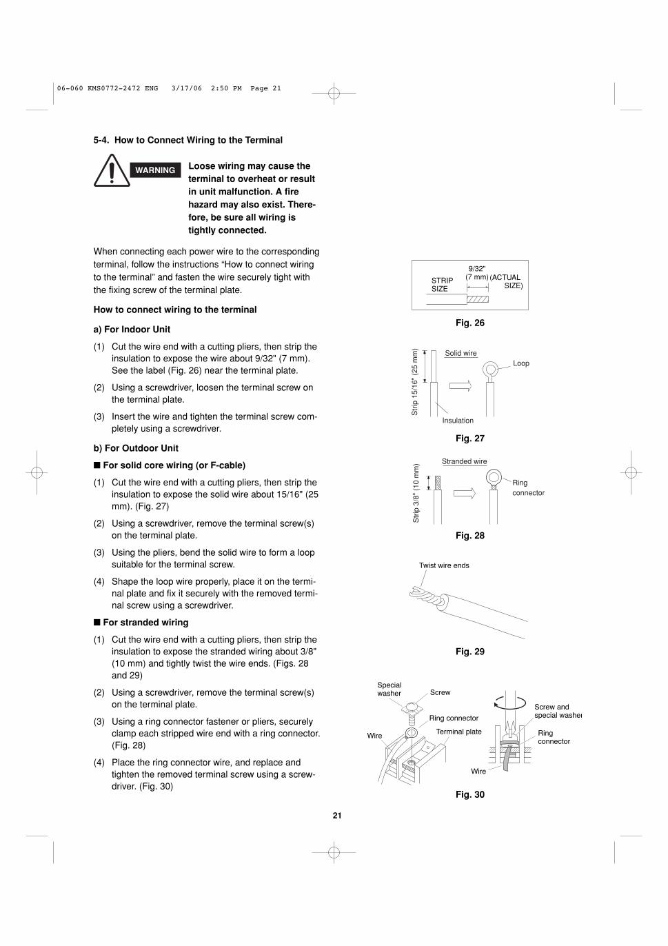
When connecting each power wire to the correspondingterminal, follow the instructions “How to connect wiringto the terminal” and fasten the wire securely tight withthe fixing screw of the terminal plate.
How to connect wiring to the terminal
a) For Indoor Unit
(1) Cut the wire end with a cutting pliers, then strip theinsulation to expose the wire about 9/32" (7 mm).See the label (Fig. 26) near the terminal plate.
(2) Using a screwdriver, loosen the terminal screw onthe terminal plate.
(3) Insert the wire and tighten the terminal screw com-pletely using a screwdriver.
b) For Outdoor Unit
� For solid core wiring (or F-cable)
(1) Cut the wire end with a cutting pliers, then strip theinsulation to expose the solid wire about 15/16" (25mm). (Fig. 27)
(2) Using a screwdriver, remove the terminal screw(s)on the terminal plate.
(3) Using the pliers, bend the solid wire to form a loopsuitable for the terminal screw.
(4) Shape the loop wire properly, place it on the termi-nal plate and fix it securely with the removed termi-nal screw using a screwdriver.
� For stranded wiring
(1) Cut the wire end with a cutting pliers, then strip theinsulation to expose the stranded wiring about 3/8"(10 mm) and tightly twist the wire ends. (Figs. 28and 29)
(2) Using a screwdriver, remove the terminal screw(s)on the terminal plate.
(3) Using a ring connector fastener or pliers, securelyclamp each stripped wire end with a ring connector.(Fig. 28)
(4) Place the ring connector wire, and replace andtighten the removed terminal screw using a screw-driver. (Fig. 30)
Solid wireLoop
InsulationS
trip
15/
16"
(25
mm
)
Fig. 27
STRIPSIZE
9/32"(7 mm) (ACTUAL
SIZE)
Fig. 26
Stranded wire
Ringconnector
Str
ip 3
/8"
(10
mm
)
Fig. 28
Screw
Ring connector
Terminal plateWire
Specialwasher
Fig. 30
Screw and special washer
Ringconnector
Wire
WARNING Loose wiring may cause theterminal to overheat or resultin unit malfunction. A firehazard may also exist. There-fore, be sure all wiring istightly connected.
Twist wire ends
Fig. 29
5-4. How to Connect Wiring to the Terminal
06-060 KMS0772-2472 ENG 3/17/06 2:50 PM Page 21
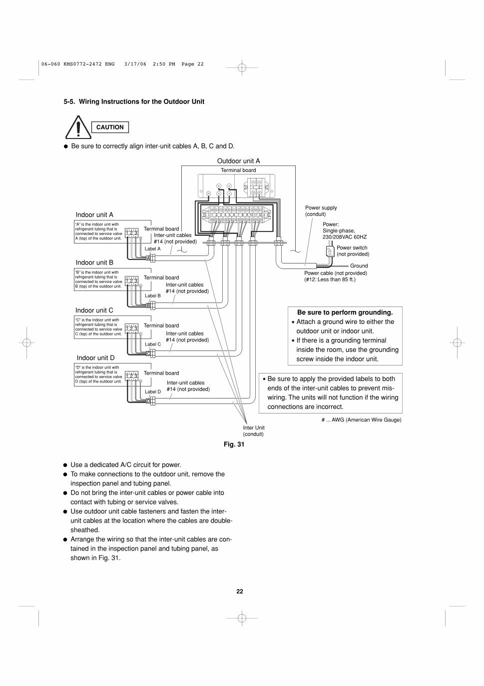
1 2 3
1 2 3
1 2 3
1 2 3
Indoor unit D
Indoor unit B
Indoor unit A
Indoor unit C
Ground
Power: Single-phase, 230/208VAC 60HZ
Power switch(not provided)
Outdoor unit ATerminal board
Label A
Inter-unit cables#14 (not provided)
Terminal board
Inter-unit cables#14 (not provided)
Terminal board
Label B
Label C
Inter-unit cables#14 (not provided)
Terminal board
Inter-unit cables#14 (not provided)
Terminal board
Label D
A
B
C
D
Power cable (not provided) (#12: Less than 85 ft.)
# ... AWG (American Wire Gauge)
Be sure to perform grounding.Attach a ground wire to either theoutdoor unit or indoor unit.If there is a grounding terminalinside the room, use the groundingscrew inside the indoor unit.
Be sure to apply the provided labels to bothends of the inter-unit cables to prevent mis-wiring. The units will not function if the wiringconnections are incorrect.
A is the indoor unit with refrigerant tubing that is connected to service valve A (top) of the outdoor unit.
refrigerant tubing that is connected to service valve B (top) of the outdoor unit.
B is the indoor unit with
refrigerant tubing that is connected to service valve C (top) of the outdoor unit.
C is the indoor unit with
refrigerant tubing that is connected to service valve D (top) of the outdoor unit.
D is the indoor unit with
1 2
1 2 3 4 5 6 7 8 9 10 11 12
Power supply(conduit)
Inter Unit(conduit)
22
5-5. Wiring Instructions for the Outdoor Unit
� Be sure to correctly align inter-unit cables A, B, C and D.
� Use a dedicated A/C circuit for power.� To make connections to the outdoor unit, remove the
inspection panel and tubing panel.� Do not bring the inter-unit cables or power cable into
contact with tubing or service valves.� Use outdoor unit cable fasteners and fasten the inter-
unit cables at the location where the cables are double-sheathed.
� Arrange the wiring so that the inter-unit cables are con-tained in the inspection panel and tubing panel, asshown in Fig. 31.
CAUTION
Fig. 31
06-060 KMS0772-2472 ENG 3/17/06 2:50 PM Page 22
23
Regulations on wire size differ from locality to locality. Forfield wiring requirements, please refer to your local electri-cal codes. Make sure that the installation fully complieswith all local and national regulations.
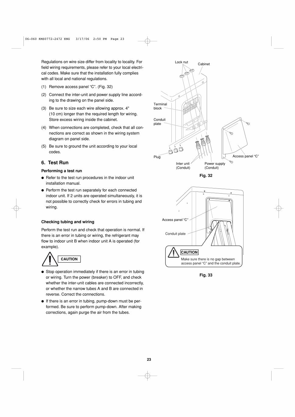
(1) Remove access panel “C”. (Fig. 32)
(2) Connect the inter-unit and power supply line accord-ing to the drawing on the panel side.
(3) Be sure to size each wire allowing approx. 4" (10 cm) longer than the required length for wiring.Store excess wiring inside the cabinet.
(4) When connections are completed, check that all con-nections are correct as shown in the wiring systemdiagram on panel side.
(5) Be sure to ground the unit according to your localcodes.
Fig. 32
Lock nut
Conduitplate
Plug
Inter unit(Conduit)
Power supply(Conduit)
Cabinet
Terminalblock
Access panel “C”
6. Test Run
Performing a test run
� Refer to the test run procedures in the indoor unitinstallation manual.
� Perform the test run separately for each connectedindoor unit. If 2 units are operated simultaneously, it isnot possible to correctly check for errors in tubing andwiring.
Checking tubing and wiring
Perform the test run and check that operation is normal. Ifthere is an error in tubing or wiring, the refrigerant mayflow to indoor unit B when indoor unit A is operated (forexample).
� Stop operation immediately if there is an error in tubingor wiring. Turn the power (breaker) to OFF, and checkwhether the inter-unit cables are connected incorrectly,or whether the narrow tubes A and B are connected inreverse. Correct the connections.
� If there is an error in tubing, pump-down must be per-formed. Be sure to perform pump-down. After makingcorrections, again purge the air from the tubes.
CAUTION
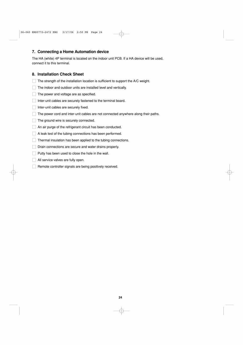
Fig. 33
Conduit plate
Make sure there is no gap between access panel “C” and the conduit plate.
Access panel C
CAUTION
06-060 KMS0772-2472 ENG 3/17/06 2:50 PM Page 23
24
7. Connecting a Home Automation device
The HA (white) 4P terminal is located on the indoor unit PCB. If a HA device will be used, connect it to this terminal.
8. Installation Check Sheet
The strength of the installation location is sufficient to support the A/C weight.
The indoor and outdoor units are installed level and vertically.
The power and voltage are as specified.
Inter-unit cables are securely fastened to the terminal board.
Inter-unit cables are securely fixed.
The power cord and inter-unit cables are not connected anywhere along their paths.
The ground wire is securely connected.
An air purge of the refrigerant circuit has been conducted.
A leak test of the tubing connections has been performed.
Thermal insulation has been applied to the tubing connections.
Drain connections are secure and water drains properly.
Putty has been used to close the hole in the wall.
All service valves are fully open.
Remote controller signals are being positively received.
06-060 KMS0772-2472 ENG 3/17/06 2:50 PM Page 24