Embed Size (px)
Citation preview

For Models HL, VF and VH Fan Coil Units
ITEM PAGE
VALVE / PIPING PACKAGE CODE DESCRIPTIONS . . . . . . . . . . . . . . . . . . . . . . . . . . . . . . . . . . . . 3
PIPING PACKAGE FEATURES AND OPTIONS . . . . . . . . . . . . . . . . . . . . . . . . . . . . . . . . . . . . . . . . 5
ISOLATION VALVE ONLY PACKAGES. . . . . . . . . . . . . . . . . . . . . . . . . . . . . . . . . . . . . . . . . . . . . . 6
2-WAY CONTROL DIAGRAMSModel HL . . . . . . . . . . . . . . . . . . . . . . . . . . . . . . . . . . . . . . . . . . . . . . . . . . . . . . . . . . . . . . . 8Models VF and VH . . . . . . . . . . . . . . . . . . . . . . . . . . . . . . . . . . . . . . . . . . . . . . . . . . . . . . . 10
3-WAY CONTROL DIAGRAMS – Models HL, VF and VH. . . . . . . . . . . . . . . . . . . . . . . . . . . . . . . 12
3-WAY CONTROL (with Balance Valve in Bypass) DIAGRAMSModels HL, VF and VH . . . . . . . . . . . . . . . . . . . . . . . . . . . . . . . . . . . . . . . . . . . . . . . . . . . . 14
GLOSSARY (Component Descriptions and Specifications)Manual Ball Valve. . . . . . . . . . . . . . . . . . . . . . . . . . . . . . . . . . . . . . . . . . . . . . . . . . . . . . . . . 16Memory Stop. . . . . . . . . . . . . . . . . . . . . . . . . . . . . . . . . . . . . . . . . . . . . . . . . . . . . . . . . . . . 16Typical 2-Way Control Valve . . . . . . . . . . . . . . . . . . . . . . . . . . . . . . . . . . . . . . . . . . . . . . . . . 16Typical 3-Way Control Valve . . . . . . . . . . . . . . . . . . . . . . . . . . . . . . . . . . . . . . . . . . . . . . . . . 17Automatic Fixed Flow Control. . . . . . . . . . . . . . . . . . . . . . . . . . . . . . . . . . . . . . . . . . . . . . . . 17Manual Circuit Setter . . . . . . . . . . . . . . . . . . . . . . . . . . . . . . . . . . . . . . . . . . . . . . . . . . . . . . 17Balancing Fitting . . . . . . . . . . . . . . . . . . . . . . . . . . . . . . . . . . . . . . . . . . . . . . . . . . . . . . . . . 18Unions. . . . . . . . . . . . . . . . . . . . . . . . . . . . . . . . . . . . . . . . . . . . . . . . . . . . . . . . . . . . . . . . . 18Y Strainer. . . . . . . . . . . . . . . . . . . . . . . . . . . . . . . . . . . . . . . . . . . . . . . . . . . . . . . . . . . . . . . 18Y Strainer with Cleanout . . . . . . . . . . . . . . . . . . . . . . . . . . . . . . . . . . . . . . . . . . . . . . . . . . . 19Optional Pressure/Temperature Test Port Locations . . . . . . . . . . . . . . . . . . . . . . . . . . . . . . . . 19Aqua-Thermostat . . . . . . . . . . . . . . . . . . . . . . . . . . . . . . . . . . . . . . . . . . . . . . . . . . . . . . . . . 19
Drawings in this catalog are subject to change without notice. Visit the ENVIRO-TEC® website at www.enviro-tec.com for current submittal drawings.
FCU PIPING PACKAGES • CONTENTS
2 Fan Coil Unit Valve Piping Packages • April, 2001 • ©2001 Environmental Technologies, Inc.
DESCRIPTIONS • FCU PIPING PACKAGES
©2001 Environmental Technologies, Inc. • April, 2001 • Fan Coil Unit Valve Piping Packages 3
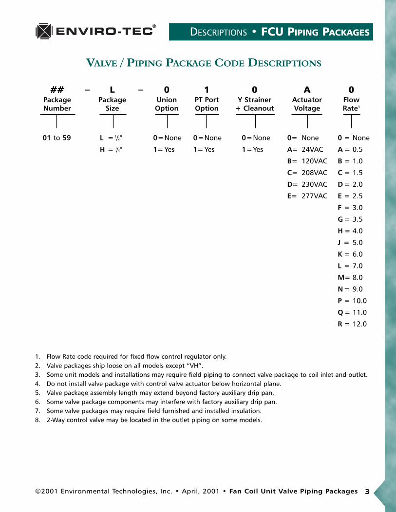
VALVE / PIPING PACKAGE CODE DESCRIPTIONS
## – L – 0 1 0 A 0Package Package Union PT Port Y Strainer Actuator FlowNumber Size Option Option + Cleanout Voltage Rate1
01 to 59 L = 1/2" 0=None 0=None 0=None 0= None 0 = None
H = 3/4" 1= Yes 1= Yes 1=Yes A= 24VAC A = 0.5
B= 120VAC B = 1.0
C= 208VAC C = 1.5
D= 230VAC D = 2.0
E= 277VAC E = 2.5
F = 3.0
G = 3.5
H = 4.0
J = 5.0
K = 6.0
L = 7.0
M= 8.0
N= 9.0
P = 10.0
Q = 11.0
R = 12.0
1. Flow Rate code required for fixed flow control regulator only.2. Valve packages ship loose on all models except “VH”.3. Some unit models and installations may require field piping to connect valve package to coil inlet and outlet.4. Do not install valve package with control valve actuator below horizontal plane.5. Valve package assembly length may extend beyond factory auxiliary drip pan.6. Some valve package components may interfere with factory auxiliary drip pan.7. Some valve packages may require field furnished and installed insulation.8. 2-Way control valve may be located in the outlet piping on some models.

FCU PIPING PACKAGES • DESCRIPTIONS
4 Fan Coil Unit Valve Piping Packages • April, 2001 • ©2001 Environmental Technologies, Inc.
GENERAL NOTES
• Control valves are piped normally closed to the coil as standard.
• 3-way valves are installed as mixing valves as standard.
• Transformer option required with 24 volt control valves unless field furnished.
• Memory stop serves as a balancing valve and is provided as an attachment to one of the ball stop iso-lation valves in the piping package.
• Unions are installed at the water coil.
• P/T test ports are located in the piping package to monitor pressure and temperature across the coil.
• Automatic fixed flow control increments are as follows: 0.5 to 4.0 GPM - 0.5 GPM; 5.0 to 9.0 GPM -1.0 GPM. Specify GPM when ordering.
• Maximum close-off pressure for 2-way control valves is 30 PSI, 3-way is 13 PSI. Contact factory whenhigher close-off pressures are required.
• A piping package diagram or detail must be submitted if accessories are required in locations otherthan indicated in the notes above. Additional engineering charges will apply and in some cases, alter-nate piping accessory locations may not be available due to dimensional or application constraints.See Valve Piping Package catalog (Stock ID CAT-FCU-PIPING). Contact factory for special pricing andauthorization number prior to quoting.
VH Notes
• A minimum of a manual piping package per coil is required on all VH units.
• Some restrictions may apply to the Y strainer with cleanout. Contact factory prior to quoting.
VF and HL Notes
• Piping packages are factory assembled and shipped loose for field installation to the fan coil unit.
• Piping packages are not available on DX or steam coils.
• Recommended water flow for 1/2" piping packages is 6.0 GPM with 25 PSIG close-off pressure maxi-mum; 3/4" is 12.5 GPM and 10 PSIG maximum. If water flow exceeds 12.5 GPM, contact factory forspecial pricing.
• 208/230/277 volt piping packages have extended lead times. Contact factory for ship cycle.
• Circuit setter is designed for full shut-off and replaces one ball stop isolation valve.
• Y strainer not available on Model HLE horizontal cabinet, or with auxiliary drip pans.

DIAGRAMS • FCU PIPING PACKAGES
©2001 Environmental Technologies, Inc. • April, 2001 • Fan Coil Unit Valve Piping Packages 5
WITH CLEANOUT
OPTIONAL Y-STRAINER
PACKAGE WITH AQUA-THERMOSTAT
TYPICAL 3-WAY CONTROL VALVE
COIL INLET AND OUTLET
PORTS TYPICAL AT
TEMPERATURE TEST
OPTIONAL PRESSURE-
TYPICAL LOCATION
OPTIONAL UNION
COOL & HEAT AUTO CHANGEOVER SYSTEMS.
3. 1/4" BLEED LINE IS FURNISHED ON 2-PIPE
LINE AND AQUA-THERMOSTAT
PACKAGE WITH 1/4" BLEED BYPASS
TYPICAL 2-WAY CONTROL VALVE
TYPE, HAND CONNECTION, AND PIPE SIZE.
PACKAGE CONFIGURATION VARIES WITH UNIT
IN RELATION TO FLUID FLOW. ACTUAL VALVE
2. THIS DIAGRAM SHOWS COMPONENT POSITION
PRIOR NOTICE.
1. ALL DRAWINGS SUBJECT TO CHANGE WITHOUT
NOTES:
Y-STRAINER Y-STRAINER W/CLEANOUT
COIL
ADJUST. FLOW SETTER
BALANCE VALVE
FIXED FLOW CONTROL VALVE
MAN. BALL VALVE W/MEM STOP
LEGEND:
TEST PORT
AQUA-THERMOSTAT
PRESSURE-TEMPERATURE
UNION
MANUAL BALL VALVE
2-WAY CONTROL VALVE
3-WAY CONTROL VALVE
COIL COIL
COILCOIL
M
M
M
M
FC
M
PIPING PACKAGE FEATURES AND OPTIONS

FCU PIPING PACKAGES • AVAILABILITY
6 Fan Coil Unit Valve Piping Packages • April, 2001 • ©2001 Environmental Technologies, Inc.
MANUAL PIPING PACKAGES
PACKAGE
CODE BV MS Y-STR FC AFS UNION PT Y CO HLF/HLP HLE VF VH
01 x x x x x x x
02 x x x x x x x x
03 x x x x x x x
04 x x x x x x x x
05 x x x x x x x x
06 x x x x x x x
07 x x x x x x x x
08 x x x x x x x
Available x
Not Available
COMPONENTS PRODUCTSOPTIONS
LEGEND
BV Manual Ball Valve(s)MS Add Memory Stop to One Ball ValveY-STR Y StrainerFC Fixed Flow ControlAFS Adjustable Flow Circuit SetterPT Pressure/Temperature Test PortY CO Y Strainer with Cleanout

DIAGRAMS • FCU PIPING PACKAGES
©2001 Environmental Technologies, Inc. • April, 2001 • Fan Coil Unit Valve Piping Packages 7
MANUAL BALL VALVES ONLY
TWO BALL VALVES
connection, and pipe size.
configuration varies with unit type, hand
relation to fluid flow. Actual valve package
2. This diagram shows component position in
notice.
1. All drawings subject to change without prior
NOTES:
& Y-STRAINER
ONE BALL VALVE, ADJUST. FLOW SETTER,& Y-STRAINER
TWO BALL VALVES, FIXED FLOW CONTROL,
ONE BALL VALVE & ADJUST. FLOW SETTERTWO BALL VALVES & FIXED FLOW CONTROL
& Y-STRAINER
TWO BALL VALVES ADD MEM. STOPTWO BALL VALVES Y-STRAINER
TWO BALL VALVES ADD MEM. STOP
000-
000-000-
00-08-
00-04-00-03-
0-07-
05- - 00 06-
02-01-
CODE - 08CODE - 07
CODE - 06CODE - 05
CODE - 03 CODE - 04
CODE - 02CODE - 01
COILCOIL
COILCOIL
COILCOIL
COILCOIL
FC
FC

FCU PIPING PACKAGES • AVAILABILITY
8 Fan Coil Unit Valve Piping Packages • April, 2001 • ©2001 Environmental Technologies, Inc.
2-WAY PIPING PACKAGES • HLPACKAGE
CODE BV MS 2W CV Y-STR FC AFS UNION PT Y CO C/O B/L HLF/HLP HLE VF VH
09 x x x x x x x
10 x x x x x x x x
11 x x x x x x x x
12 x x x x x x x x
13 x x x x x x x x x
14 x x x x x x x x x
15 x x x x x x x
16 x x x x x x x x
17 x x x x x x
18 x x x x x x x
19 x x x x x x
20 x x x x x x x
21 x x x x x x x x
22 x x x x x x x
Available x
Not Available
NON-CATALOGUED PACKAGES (Contact Factory)
COMPONENTS PRODUCTSOPTIONS
LEGEND
BV Manual Ball Valve(s)MS Add Memory Stop to One Ball Valve2W CV 2-Way Control ValveY-STR Y StrainerFC Fixed Flow ControlAFS Adjustable Flow Circuit SetterPT Pressure/Temperature Test PortY CO Y Strainer with CleanoutC/O B/L Changeover Bleed Line
(On 2-way piping packages, a bleed line is required to ensure water circulation when valve is closed. Not required on 3-way piping packages).

DIAGRAMS • FCU PIPING PACKAGES
©2001 Environmental Technologies, Inc. • April, 2001 • Fan Coil Unit Valve Piping Packages 9
(4) (4) (4)
(4)(4)(4)
2-WAY CONTROL VALVE ONLY
FACTORY.
4. NON-CATALOGED VALVE PACKAGE. CONTACT
COOL & HEAT AUTO CHANGEOVER SYSTEMS.
3. 1/4" BLEED LINE IS FURNISHED ON 2-PIPE
ADJUST. FLOW SETTER, & Y-STRAINER
2-WAY CONTROL VALVE W/BALL VALVE,ADJUST. FLOW SETTER
2-WAY CONTROL VALVE W/BALL VALVE &
& Y-STRAINER
ADD MEMORY STOP,
2-WAY CONTROL VALVE W/BALL VALVES,
CONTROL, & Y-STRAINER
FIXED FLOW
2-WAY CONTROL VALVE W/BALL VALVES,
VALVES & Y-STRAINER
2-WAY CONTROL VALVE W/BALL
FIXED FLOW CONTROL
2-WAY CONTROL VALVE W/BALL VALVES &
ADD MEMORY STOP
2-WAY CONTROL VALVE W/BALL VALVES,
SETTER & Y-STRAINER
2-WAY CONTROL VALVE W/ADJUST. FLOW
W/BALL VALVES
2-WAY CONTROL VALVE
CONTROL & Y-STRAINER
2-WAY CONTROL VALVE W/FIXED FLOW
W/Y-STRAINER
2-WAY CONTROL VALVE
FLOW SETTER
2-WAY CONTROL VALVE W/ADJUST.
TYPE, HAND CONNECTION, AND PIPE SIZE.
PACKAGE CONFIGURATION VARIES WITH UNIT
IN RELATION TO FLUID FLOW. ACTUAL VALVE
2. THIS DIAGRAM SHOWS COMPONENT POSITION
PRIOR NOTICE.
1. ALL DRAWINGS SUBJECT TO CHANGE WITHOUT
NOTES:
FLOW CONTROL
2-WAY CONTROL VALVE W/FIXED
14- -
21- -
0-16-
0-13-0-12-
0-22-0-20-
0-11-
0-18-
00-15-
00-10-00-09-
00-19-00-17-
CODE - 16CODE - 15
CODE - 12 CODE - 13 CODE - 14
CODE - 11CODE - 10CODE - 09
CODE - 20 CODE - 21 CODE - 22
CODE - 19 CODE - 18 CODE - 17
COILCOIL
COILCOILCOIL
COIL COIL COIL
COIL COIL COIL
COILCOILCOIL
M M
M
FC
MM
M M M
FC
M
FC
MM
M
FC
MM
2-WAY CONTROL VALVE • MODEL HL

FCU PIPING PACKAGES • AVAILABILITY
10 Fan Coil Unit Valve Piping Packages • April, 2001 • ©2001 Environmental Technologies, Inc.
2-WAY PIPING PACKAGES • VF & VHPACKAGE
CODE BV MS 2W CV Y-STR FC AFS UNION PT Y CO C/O B/L HLF/HLP HLE VF VH
23 x x x x x x x
24 x x x x x x x x
25 x x x x x x x x
26 x x x x x x x x
27 x x x x x x x x x
28 x x x x x x x x x
29 x x x x x x
30 x x x x x x
31 x x x x x x x x
32 x x x x x
33 x x x x x
34 x x x x x x
Available x
Not Available
NON-CATALOGUED PACKAGES (Contact Factory)
COMPONENTS OPTIONS PRODUCTS
LEGEND
BV Manual Ball Valve(s)MS Add Memory Stop to One Ball Valve2W CV 2-Way Control ValveY-STR Y StrainerFC Fixed Flow ControlAFS Adjustable Flow Circuit SetterPT Pressure/Temperature Test PortY CO Y Strainer with CleanoutC/O B/L Changeover Bleed Line
(On 2-way piping packages, a bleed line is required to ensure water circulation when valve is closed. Not required on 3-way piping packages).

DIAGRAMS • FCU PIPING PACKAGES
©2001 Environmental Technologies, Inc. • April, 2001 • Fan Coil Unit Valve Piping Packages 11
2-WAY CONTROL VALVE • MODELS VF & VH
FACTORY.
4. NON-CATALOGED VALVE PACKAGE. CONTACT
(4)(4)(4)
(MODEL "VH" ONLY)(MODEL "VF" ONLY)
FLOW CONTROL
2-WAY CONTROL VALVE W/FIXED
ADJUST. FLOW SETTER
2-WAY CONTROL VALVE & 2-WAY CONTROL VALVE ONLY
VALVE & ADJUST. FLOW SETTER
2-WAY CONTROL VALVE W/BALL
COOL & HEAT AUTO CHANGEOVER SYSTEMS.
3. 1/4" BLEED LINE IS FURNISHED ON 2-PIPE
& Y-STRAINER
ADJUST. FLOW SETTER,
2-WAY CONTROL VALVE W/BALL VALVES,
ADJUST. FLOW SETTER
2-WAY CONTROL VALVE W/BALL VALVES &
STOP, & Y-STRAINER
W/BALL VALVES, ADD MEMORY
2-WAY CONTROL VALVE
& Y-STRAINER
FIXED FLOW CONTROL,
2-WAY CONTROL VALVE W/BALL VALVES,VALVES & Y-STRAINER
2-WAY CONTROL VALVE W/BALL
FIXED FLOW CONTROL
2-WAY CONTROL VALVE W/BALL VALVES &
ADD MEMORY STOP
2-WAY CONTROL VALVE W/BALL VALVES,
W/BALL VALVES
2-WAY CONTROL VALVE
TYPE, HAND CONNECTION, AND PIPE SIZE.
PACKAGE CONFIGURATION VARIES WITH UNIT
IN RELATION TO FLUID FLOW. ACTUAL VALVE
2. THIS DIAGRAM SHOWS COMPONENT POSITION
PRIOR NOTICE.
1. ALL DRAWINGS SUBJECT TO CHANGE WITHOUT
NOTES:
0-31-
0-27-0-26-
0-34-
0-25-
0 0-33-0 0-32-
0 0-29- 0 0-30-
0 0-24-0 0-23-
-28-
CODE - 34
CODE - 29
CODE - 28
CODE - 25
CODE - 33
CODE - 31
CODE - 27
CODE - 24
CODE - 32
CODE - 30
CODE - 26
CODE - 23
COILCOILCOIL
COIL COILCOIL
COILCOILCOIL
COIL COIL COIL
M
FC
FC
FC
M
M
M
M
M
M
M
M
M
M
M

FCU PIPING PACKAGES • AVAILABILITY
12 Fan Coil Unit Valve Piping Packages • April, 2001 • ©2001 Environmental Technologies, Inc.
3-WAY PIPING PACKAGES
PACKAGE
CODE BV MS 3W CV Y-STR FC AFS UNION PT Y CO HLF/HLP HLE VF VH
35 x x x x x x x x
36 x x x x x x x x x
37 x x x x x x x x x
38 x x x x x x x x
39 x x x x x x x x x
40 x x x x x x x x x
41 x x x x x x x x
42 x x x x x x x x
43 x x x x x x
44 x x x x x x x
45 x x x x x x
46 x x x x x x
47 x x x x x x x
48 x x x x x x
Available x
Not Available
NON-CATALOGUED PACKAGES (Contact Factory)
COMPONENTS PRODUCTSOPTIONS
LEGEND
BV Manual Ball Valve(s)MS Add Memory Stop
to One Ball Valve3W CV 3-Way Control ValveY-STR Y Strainer
FC Fixed Flow ControlAFS Adjustable Flow Circuit SetterPT Pressure/Temperature Test PortY CO Y Strainer with Cleanout

DIAGRAMS • FCU PIPING PACKAGES
©2001 Environmental Technologies, Inc. • April, 2001 • Fan Coil Unit Valve Piping Packages 13
(3) (3) (3)
FACTORY.
3. NON-CATALOGED VALVE PACKAGE. CONTACT
(3)(3)(3)
W/Y-STRAINER
3-WAY CONTROL VALVE ONLY
ADJUST. FLOW SETTER, & Y-STRAINER
3-WAY CONTROL VALVE W/BALL VALVES,& ADJUST. FLOW SETTER
3-WAY CONTROL VALVE, W/BALL VALVE
FLOW CONTROL, & Y-STRAINER
3-WAY CONTROL VALVE W/BALL VALVES, FIXEDMEMORY STOP & Y-STRAINER
3-WAY CONTROL VALVE W/BALL VALVES, ADD
VALVES & Y-STRAINER
3-WAY CONTROL VALVE W/BALL
FIXED FLOW CONTROL
3-WAY CONTROL VALVE W/BALL VALVES &
ADD MEMORY STOP
3-WAY CONTROL VALVE W/BALL VALVES,
W/BALL VALVES
3-WAY CONTROL VALVE
FLOW SETTER & Y-STRAINER
3-WAY CONTROL VALVE W/ADJUST.
CONTROL & Y-STRAINER
3-WAY CONTROL VALVE W/FIXED FLOW
FLOW SETTER
3-WAY CONTROL VALVE W/ADJUST.
VALVE ONLY
3-WAY CONTROL
TYPE, HAND CONNECTION, AND PIPE SIZE.
PACKAGE CONFIGURATION VARIES WITH UNIT
IN RELATION TO FLUID FLOW. ACTUAL VALVE
2. THIS DIAGRAM SHOWS COMPONENT POSITION
PRIOR NOTICE.
1. ALL DRAWINGS SUBJECT TO CHANGE WITHOUT
NOTES:
FLOW CONTROL
3-WAY CONTROL VALVE W/FIXED
-40-
-47-
0-42-
0-39-0-38-
0-48-0-46-
-37- 0
-44- 0
0-41- 0
0-36- 00-35- 0
0-45- 00-43- 0
CODE - 41 CODE - 42
CODE - 38 CODE - 39 CODE - 40
CODE - 37CODE - 36CODE - 35
CODE - 46 CODE - 47 CODE - 48
CODE - 45CODE - 44CODE - 43
COILCOIL
COILCOILCOIL
COILCOILCOIL
COILCOILCOIL
COILCOILCOILFC
FC
FC
MM
M M MMMM
FCM M MMMM
3-WAY CONTROL VALVE • MODELS HL, VF & VH

FCU PIPING PACKAGES • AVAILABILITY
14 Fan Coil Unit Valve Piping Packages • April, 2001 • ©2001 Environmental Technologies, Inc.
3-WAY PIPING PACKAGE WITH BALANCE BYPASS VALVE
PACKAGE
CODE BV MS 3W CV BPBV Y-STR FC AFS UNION PT Y CO HLF/HLP HLE VF VH
49 x x x x x x x x x
50 x x x x x x x x x x
51 x x x x x x x x x
52 x x x x x x x x x x
53 x x x x x x x x
54 x x x x x x x x
55 x x x x x x
56 x x x x x x x
57 x x x x x x x
58 x x x x x x x
59 x x x x x x x
Available x
Not Available
NON-CATALOGUED PACKAGES (Contact Factory)
COMPONENTS PRODUCTSOPTIONS
LEGEND
BV Manual Ball Valve(s)MS Add Memory Stop
to One Ball Valve3W CV 3-Way Control ValveBPBV Bypass Balance Valve
Y-STR Y StrainerFC Fixed Flow ControlAFS Adjustable Flow Circuit SetterPT Pressure/Temperature Test PortY CO Y Strainer with Cleanout

DIAGRAMS • FCU PIPING PACKAGES
©2001 Environmental Technologies, Inc. • April, 2001 • Fan Coil Unit Valve Piping Packages 15
3-WAY CONTROL VALVE WITH BALANCE BYPASS VALVE
MODELS HL, VF & VH
FACTORY.
3. NON-CATALOGED VALVE PACKAGE. CONTACT
& ADJUST. FLOW SETTER
BYPASS, TWO BALL VALVES
3-WAY CONTROL VALVE W/BALANCE VALVE IN
& ADJUST. FLOW SETTER
BYPASS, ONE BALL VALVE,
3-WAY CONTROL VALVE W/BALANCE VALVE IN
ADJUST. FLOW SETTER, & Y-STRAINER
IN BYPASS, ONE BALL VALVE,
3-WAY CONTROL VALVE W/BALANCE VALVE
BYPASS, TWO BALL VALVES, & Y-STRAINER
3-WAY CONTROL VALVE W/BALANCE VALVE IN
& Y-STRAINER
TWO BALL VALVES, ADD MEMORY STOP,
3-WAY CONTROL VALVE W/BALANCE VALVE IN BYPASS,
VALVES, ADD MEMORY STOP
VALVE IN BYPASS & TWO BALL
3-WAY CONTROL VALVE W/BALANCE
BYPASS & TWO BALL VALVES
3-WAY CONTROL VALVE W/BALANCE VALVE IN
BYPASS & ADJUST. FLOW SETTER
3-WAY CONTROL VALVE W/BALANCE VALVE IN
ADJUST. FLOW SETTER, & Y-STRAINER
3-WAY CONTROL VALVE W/BALANCE VALVE IN BYPASS,
VALVE IN BYPASS & Y-STRAINER
3-WAY CONTROL VALVE W/BALANCE
VALVE IN BYPASS
3-WAY CONTROL VALVE W/BALANCE
TYPE, HAND CONNECTION, AND PIPE SIZE.
PACKAGE CONFIGURATION VARIES WITH UNIT
IN RELATION TO FLUID FLOW. ACTUAL VALVE
2. THIS DIAGRAM SHOWS COMPONENT POSITION
PRIOR NOTICE.
1. ALL DRAWINGS SUBJECT TO CHANGE WITHOUT
NOTES:
(3)(3)
(3)(3)
0-54-
0-52-0-51-
0-59-
0-57-
00-55-00-53-
00-50-00-49-
00-58-
00-56-
CODE - 55CODE - 54CODE - 53
CODE - 51 CODE - 52
CODE - 50
CODE - 58
CODE - 49
CODE - 59
CODE - 57CODE - 56
COILCOIL COIL
COIL COIL
COILCOIL
COIL COIL
COILCOIL
MMM
MMM
MM M
MM

FCU PIPING PACKAGES • GLOSSARY
16 Fan Coil Unit Valve Piping Packages • April, 2001 • ©2001 Environmental Technologies, Inc.
Manual Ball ValveA full port forged brass ball valve used to isolate the FanCoil Unit and/or associated piping. The valve requires man-ual operation.
Nominal Size: ½" ¾"Body Material: Brass BrassBall: Hard Chrome Hard Chrome
Plated PlatedSeats: Teflon TeflonStem Seal: (2) Viton O-Rings (2) Viton O-RingsConnection: Sweat SweatPressure Rating (psig): 600 600Temp. Rating, °F: 325 325Cv: 21 42
Manual Ball Valve With Memory StopAn adjustable stop position lever to limit travel of the On/Offhandle. This allows the ball valve to be closed, and returnedto the balance setting position without re-testing the system.
(See above ratings).
Typical 2-Way Control ValveA 2-position water control valve driven open or closed upona call for heating or cooling to maintain space tempera-ture. In open position, water can flow through the FanCoil Unit‘s water coil to heat or cool the space depend-ing on supply water temperature. In closed position, watercannot flow through the water coil. Control valves arepiped normally closed to the coil as standard. Valve actu-ators can be line or low (24VAC) voltage.
Nominal Size: ½" 2-Way ¾" 2-WayBody Material: Brass BrassConnection: Sweat SweatPressure Rating (psig): 300 300Temp. Rating, °F: 200 200Cv: 2.5 5.0Max. Close-off Press. (psig): 30 13Power Consumption: 7VA 7VA
NOTE: Photos are for representation purposes only. Vendors and models subject to change without notice.

GLOSSARY • FCU PIPING PACKAGES
©2001 Environmental Technologies, Inc. • April, 2001 • Fan Coil Unit Valve Piping Packages 17
Manual Circuit SetterA control fitting designed to allow maximum water flowthrough the Fan Coil Unit in the Open (0%) position, andas little as 10% of flow through the Fan Coil Unit in theClosed (90%) position. Has a calibrated nameplate, builtin test ports and adjustable mechanical stops, and is suit-able for positive shutoff.
Nominal Size: ½" & ¾"Body Material: BronzeConnection: SweatPressure Rating (psig): 300Temp. Rating, °F: 250Cv: Variable
Automatic Fixed Flow ControlA pressure compensated automatic fixed flow control devicedesigned to limit the GPM (gallons per minute) flow throughthe Fan Coil Unit. Automatic fixed flow control incrementsare: 0.5 to 4.0 GPM (in 0.5 GPM increments) and 5.0 to20.0 GPM (in 1.0 GPM increments), ±10%. Desired GPMmust be specified when ordering.
Nominal Size: ½" & ¾"Body Material: CopperConnection: SweatPressure Rating (psig): 500Temp. Rating, °F: 225Cv: Variable With
Inlet Pressure
Typical 3-Way Control ValveA 2-position water control valve driven open or closed (bypass)upon a call for heating or cooling to maintain space tempera-ture. Energized, water can flow through the Fan Coil Unit‘s watercoil to heat or cool the space depending on the supply watertemperature. The bypass port is blocked. De-energized, watercannot flow through the water coil but is forced to flow throughthe bypass port, bypassing the coil. Control valves are pipednormally closed to the coil as standard (in full bypass). Valveactuators can be line or low (24VAC) voltage.
Nominal Size: ½" 3-Way ¾" 3-WayBody Material: Brass BrassConnection: Sweat SweatPressure Rating (psig): 300 300Temp. Rating, °F: 200 200Cv: 3.0 5.0Max. Close-off Press. (psig): N/A N/APower Consumption: 7VA 7VA
NOTE: Photos are for representation purposes only. Vendors and models subject to change without notice.
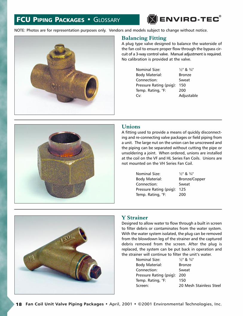
UnionsA fitting used to provide a means of quickly disconnect-ing and re-connecting valve packages or field piping froma unit. The large nut on the union can be unscrewed andthe piping can be separated without cutting the pipe orunsoldering a joint. When ordered, unions are installedat the coil on the VF and HL Series Fan Coils. Unions arenot mounted on the VH Series Fan Coil.
Nominal Size: ½" & ¾"Body Material: Bronze/CopperConnection: SweatPressure Rating (psig): 125Temp. Rating, °F: 200
Y StrainerDesigned to allow water to flow through a built in screento filter debris or contaminates from the water system.With the water system isolated, the plug can be removedfrom the blowdown leg of the strainer and the captureddebris removed from the screen. After the plug isreplaced, the system can be put back in operation andthe strainer will continue to filter the unit‘s water.
Nominal Size: ½" & ¾"Body Material: BronzeConnection: SweatPressure Rating (psig): 200Temp. Rating, °F: 150Screen: 20 Mesh Stainless Steel
FCU PIPING PACKAGES • GLOSSARY
18 Fan Coil Unit Valve Piping Packages • April, 2001 • ©2001 Environmental Technologies, Inc.
Balancing FittingA plug type valve designed to balance the waterside ofthe fan coil to ensure proper flow through the bypass cir-cuit of a 3-way control valve. Manual adjustment is required.No calibration is provided at the valve.
Nominal Size: ½" & ¾"Body Material: BronzeConnection: SweatPressure Rating (psig): 150Temp. Rating, °F: 200Cv: Adjustable
NOTE: Photos are for representation purposes only. Vendors and models subject to change without notice.

GLOSSARY • FCU PIPING PACKAGES
©2001 Environmental Technologies, Inc. • April, 2001 • Fan Coil Unit Valve Piping Packages 19
Optional Pressure/Temperature Test Port LocationsDesigned to allow testing of water pressure, differentialpressure or water temperature without interrupting thewaterside operation of the Fan Coil Unit. Sensor probes(1/8") are not included.
Nominal Size: ¼"Body Material: BrassConnection: ThreadedPressure Rating (psig): 400Temp. Rating, °F: 250
Aqua ThermostatAlso called an Automatic Seasonal Changeover Switch.The Aquastat is a line or low voltage changeover switchdesigned to switch a thermostat from heating to cooling based on a change in supply water temperature.Can be mounted on ½" or ¾" copper tube. Switchingaction is SPDT.Specifications: Switch on temperature rise, 85° (±6°)
Switch on temperature fall, 70° (±6°)Current Rating:- 5.8 FLA, 34.8 LRA (inductive); 10 amps (resistive) at 120VAC - 2.9 FLA, 17.4 LRA (inductive); 5 amps (resistive) at 240VAC- 3.6 FLA, 21.6 LRA (inductive); 1 amps (resistive) at 277VACAgency Approval: UL Listed, CSA Approved
Note: Specifications may vary.
Cleanout Valve for Y StrainerA standard ball valve with a cleanout valve installed onthe strainer blowdown leg to allow flushing the strainerscreen without removing the plug in the blowdown leg.This valve has a standard ½" garden hose connection toallow fluid to be piped to a container or remote locationduring cleaning.
Nominal Size: ½"Body Material: BronzeConnection: SweatPressure Rating (psig): 125Temp. Rating, °F: 200
NOTE: Photos are for representation purposes only. Vendors and models subject to change without notice.

Research & Development, Engineering, and Manufacturing. • Variable Volume Terminals• Fan Coil Units• Air Handling Units• Blower Coil Units• Grilles, Registers and Diffusers, & Fire Dampers• Electronic Controls
6750 Bryan Dairy Rd. • Largo, FL 33777www.enviro-tec.com
727-541-3531
©2001 Environmental Technologies, Inc.Stock ID: CAT-FCU-PIPING
April, 2001 • Part No. PX-00-0018


![SAPTAHIK Nepali National Weekly Friday, June 5, 2009 vf]hL gfO6 …himalaya.socanth.cam.ac.uk/collections/journals/saptahik/... · 2015-10-27 · z'qmaf/, h7 @@, @)^^] June 5, 2009](https://img.dokumen.tips/doc/110x75/5f5ec2d696cc9535d54c8b37/saptahik-nepali-national-weekly-friday-june-5-2009-vfhl-gfo6-2015-10-27-zqmaf.jpg)


![U VF 5DQND3HWULQRYLü ... · 867 qdnqdgx 15 7r vxxjryrulnrmlpdmhsuhgphwqhnlsorylgehqlsrvdr lvnrulãwdydqmh eurgd udgl sorylgeh eh] re]lud rvwyduxmh ol vh sorylged sulmhyr]rp vwydul](https://img.dokumen.tips/doc/110x75/5c7717c309d3f229578b6b65/u-vf-5dqnd3hwulqrylue-867-qdnqdgx-15-7r-vxxjryrulnrmlpdmhsuhgphwqhnlsorylgehqlsrvdr.jpg)


![iks0vkW0&xq#dqy dkaxMh+ ] gfj}kj · 2 lgk;d vfHk;kstu vf/kdkjh inkas ij p;u grq ik= vH;fFkZ;ksa ls mRrjk[k.M yksd lsok vk;ksx }kjk lgk;d vfHk;kstu vf/kdkjh &2016 ds vUrxZr](https://img.dokumen.tips/doc/110x75/5b14d9597f8b9ab6778c4ee8/iks0vkw0xqdqy-dkaxmh-gfjkj-2-lgkd-vfhkkstu-vfkdkjh-inkas-ij-pu-grq.jpg)