Embed Size (px)
Citation preview

Approved Products for
Lower Volume Local Roads
PUB 447 (2-19)www.penndot.gov
COMMONWEALTH OF PENNSYLVANIADepartment of Transportation
Bureau of Planning & Research400 North Street, 6th FloorHarrisburg, PA 17120
PUBLICATION 447APPROVED PRODUCTS FOR LOWER VOLUME LOCAL ROADS
Publication 447 contains a listing of approved Products or Processes that meet the Bureau ofPlanning & Research specification requirements and are eligible for Liquid Fuels Funds for use onmunicipal maintenance and construction projects. Products or Processes listed in this publicationmust perform satisfactorily and be in compliance with the terms of this publication. All materialsaccepted on any project shall comply with the applicable section of the Departments specificationsor be approved by a Department representative. Publication 447 is issued by the Bureau of Planning & Research to list Products or Processes eligible for use with Liquid Fuels Funds.
For the purpose of this program Lower Volume Local Roads are classified as:
• Type D roads-Collector Highways (rural routes with light to moderate traffic)• Type E roads-Local Access Highways• Municipal or County owned roads (roads with light to moderate traffic)
Publication 447 provides municipalities with a listing of products that are eligible for Liquid FuelsFunds. That does not mean that these are the only products available to municipalities. Products/processes listed in other PennDOT Publications (Publication 408 and Bulletin 15 for example)may be eligible as well. If you have any questions about this please contact your local MunicipalServices Representative.
Manufacturers, precasters or fabricators with Products or Processes listed in Publication 447 arerequired to notify the Bureau of Planning & Research of any change to their contact information. Itis required that the Bureau have uninterrupted communication with the Suppliers/Manufacturers ofthe Products or Processes listed in Publication 447. Non-compliance may result in the removal ofthe Product or Process from Publication 447.
Product or Process applications must be submitted by the manufacturer, precaster or fabricator to have their company listed in Publication 447. Suppliers or distributors may obtain approved materials from a company listed in Publication 447 for resale to approved contractors.
https://www.penndot.gov/ProjectAndPrograms/ResearchandTesting/Pages/New-Products-Evalua-tion-And-Research-Product-Evaluation.aspxIf it is desired to have a Product or Process included in Publication 447 the applicant should referto this link on the PennDOT Website
https://www.penndot.gov/ProjectAndPrograms/ResearchandTesting/Pages/New-Products-Evalua-tion-And-Research-Product-Evaluation.aspxor call the New Products Evaluation Program at 717-783-3721

Once the Product or Process is approved it will remain in Publication 447 unless one of the following occurs:
A. Failure to meet specification requirements
B. The operation is inactive for two years
C. Failure to notify the Bureau of Planning & Research of major changes in equipment or procedures that affect the quality of the product
D. PennDOT revokes approved status
E. Removal of a plant and/or facility from approved status
F. Any safety related issue
G. Poor performance
H. Hazardous conditions
I. Non-Use
The New Products Evaluation Program for Lower Volume Local Roads and municipal requirements are bound by all applicable sections of Publication 408.
In order to use a Product or Process in Publication 447 an approved MS-329 Project ApprovalForm is required. Contact your District Municipal Services Representative when you have a project you want to have evaluated and they will complete the MS-329. Publication 9-“Policies and Procedures for the Administration of the County Liquid Fuels Tax Act of 1931 and The LiquidFuels Tax Act 655 dated 1956 and as Amended” use: contains the appropriate information.
http://www.dot.state.pa.us/public/PubsForms/Publications/PUB%209.pdf
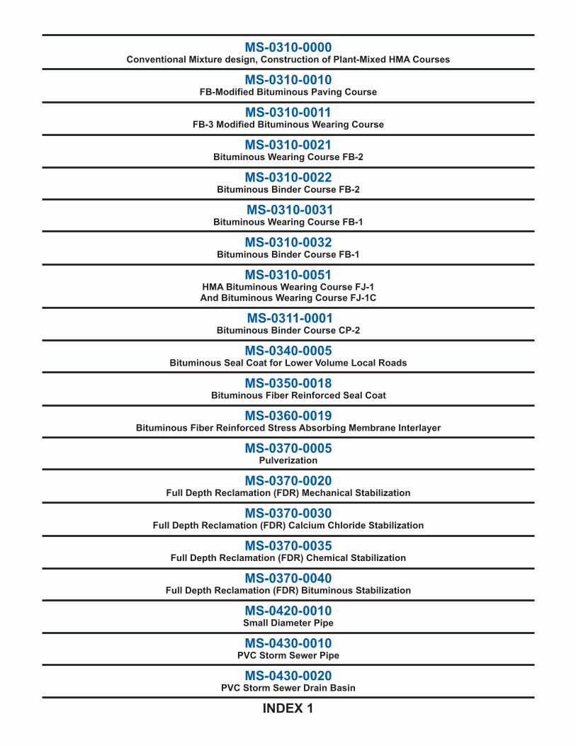
MS-0310-0000Conventional Mixture design, Construction of Plant-Mixed HMA Courses
MS-0310-0010FB-Modified Bituminous Paving Course
MS-0310-0011FB-3 Modified Bituminous Wearing Course
MS-0310-0021Bituminous Wearing Course FB-2
MS-0310-0022Bituminous Binder Course FB-2
MS-0310-0031Bituminous Wearing Course FB-1
MS-0310-0032Bituminous Binder Course FB-1
MS-0310-0051HMA Bituminous Wearing Course FJ-1And Bituminous Wearing Course FJ-1C
MS-0311-0001Bituminous Binder Course CP-2
MS-0340-0005Bituminous Seal Coat for Lower Volume Local Roads
MS-0350-0018Bituminous Fiber Reinforced Seal Coat
MS-0360-0019Bituminous Fiber Reinforced Stress Absorbing Membrane Interlayer
MS-0370-0005Pulverization
MS-0370-0020Full Depth Reclamation (FDR) Mechanical Stabilization
MS-0370-0030Full Depth Reclamation (FDR) Calcium Chloride Stabilization
MS-0370-0035Full Depth Reclamation (FDR) Chemical Stabilization
MS-0370-0040Full Depth Reclamation (FDR) Bituminous Stabilization
MS-0420-0010Small Diameter Pipe
MS-0430-0010PVC Storm Sewer Pipe
MS-0430-0020PVC Storm Sewer Drain Basin
INDEX 1

MS-0440-0020Dust Palliatives
MS-0450-0001Municipal Anti-Skid
MS-0450-0004Driving Surface Aggregate (DSA)
MS-0460-0010GRS Use and Design Guidelines
MS-0460-0011GRS
MS-0460-0020Timber Slab Span Bridge
MS-0470-0010Salt Brine
MS-0470-0011Salt Brine Attachment 1
MS-0510-0005Sign Post Reflective Panels
MS-0520-0022Patterned Thermoplastic Crosswalks
MS-0530-0024Patterned/Textured Crosswalks
MS-0540-0035Thermoplastic Manhole Protection Rings
INDEX 2
Section 300 Bituminous Materials & FDR

0310-0000CONVENTIONAL MIXTURE DESIGN, CONSTRUCTION
OF PLANT-MIXED HMA COURSES
I. DESCRIPTION—Provide plant mixed HMA/WMA courses as indicated on a prepared surface using a conventional mixture design (Modified Marshall Procedure).
II. MATERIAL—
A. Bituminous Material.
1. Virgin Mix or Mix Containing 5% to 15% RAP. Furnish the type and class of bituminous material required by the applicable pavement section and as specified in Pub. 408 Section 702, at the point of delivery and at the bituminous concrete plant. Furnish material conforming to the requirements of Standard Specifications for Performance-Graded Asphalt Binder, AASHTO M 320, except as revised in Bulletin 25. Obtain material from a source listed in Bulletin 15 for the specified grade. Provide QC testing and certification as specified in Pub. 408 Sections 106.03(b) and 702.1(b)1. Provide the Representative with a copy of a signed Certificate of Compliance (CS-4171), a Bill of Lading, and a Certificate of Analysis for bituminous material on the first day of paving and when the batch number changes.
2. Mix Containing more than 15% RAP. The MTD will evaluate the asphalt content in the RAP source material. The MTD will determine the class (grade) of asphalt cement and recycling agent the Contractor is required to use in the mixture.
Furnish the type and class of bituminous material required by the applicable pavement section and as specified in Pub. 408 Section 702, at the point of delivery and at the bituminous concrete plant. Furnish material conforming to the requirements of Standard Specifications for Performance-Graded Asphalt Binder, AASHTO M 320, except as revised in Bulletin 25. Obtain material from a source listed in Bulletin 15 for the specified grade. Provide QC testing and certification as specified in Pub. 408 Sections 106.03(b) and 702.1(b)1. Provide the Representative with a copy of a signed Certificate of Compliance (CS-4171), a Bill of Lading, and a Certificate of Analysis for bituminous material on the first day of paving and when the batch number changes.
B. Aggregates and RAM. Provide aggregate from sources listed in Bulletin 14 and conforming to the gradation of Table A. If using RAM, conform to the applicable quality requirements of Pub. 408 Section 703.1, Table A, or Pub. 408 Section 703.2, Table B. For wearing courses, provide aggregate with at least the SRL designation specified. To achieve the specified SRL, the Contractor may provide a blend of two aggregates if the blend has an SRL designation equal to or better than that specified. Blends are 50% by mass (weight) of each aggregate. Blend the aggregates using an approved method.
C. RAP. If RAP material is proposed for use in the mixture, use at least 5% RAP consisting of cold-milled or crushed hot-mix bituminous mixtures. Include a plan to control RAP and the procedures to handle RAP of significantly different composition in the producer’s QC Plan. Maintain all processed material free of foreign materials and minimize segregation. Process the RAP so that the final mixture conforms to Section 0310-0000.II.E.
D. Filler. If required, as specified in Pub. 408 Section 703.1(c)1.
E. Mixture Composition.
1. Virgin Material Mixtures. Test materials, proportions, and the mixture at the producer’s laboratory. Design the mixture according to the requirements of Bulletin 27 Chapter 2. The JMF shall include a list of sources used to provide materials and identify the mixture producer. The JMF shall conform to the following:
• The production limits of this Section for apparent moisture content, stability, flow, and Voids in Mineral Aggregate (VMA).
• The aggregate and asphalt content requirements of Table A.
300 - 1

300 - 2
If the Department has not used the JMF on previous projects, provide test results from previous mixture production that show the mixture conformed to all JMF production tolerances. Submit a copy of each completed JMF, signed by a certified HMA Level 2 plant technician, to the District Materials Manager/District Materials Engineer (DMM/DME) at least 3 weeks before the planned start of mixture production. Do not start mixture production until after the DMM/DME reviews and approves the JMF.
Submit a new JMF with a change in material sources or if a new JMF is necessary to produce a mixture conforming to this specification.
a. Producer QC Plan. Each producer must prepare a QC Plan as specified in Pub. 408 Section 106 and conforming to the additional QC requirements of this specification. Submit the QC Plan to the DMM/DME annually, but at least 3 weeks before the planned start of mixture production and do not start mixture production until the DMM/DME reviews the QC Plan.
1. QC Organization Chart.
Names of personnel responsible for QC.
Area of responsibility of each individual.
List outside agencies, e.g., testing laboratories and a description of services provided.
2. Testing Plan with Action Points.
List of all tests to be performed.
Frequency of testing.
List action points to initiate corrective procedures.
Recording method to document corrective procedures.
Procedures for conducting JMF verification testing.
3. Materials Storage and Handling.
Aggregate/RAP/RAM stockpiles.
Cold-feed systems for aggregates/RAP/RAM.
Additives or modifiers for mixture.
Modified asphalt/liquid additive storage tanks.
Surge/storage silos for mixture.
All measuring and conveying devices, including calibration procedures.
Haul vehicle loading procedures.
b. Mixture Production. During mixture production, provide a certified HMA Level 1 plant technician at the plant and an on-call certified HMA Level 2 plant technician, both meeting the requirements outlined in Publication 351. Instruct and train the certified technician to perform all tests and to control plant operation. The Department may use its own certified HMA plant technicians to verify tests and to work in close cooperation with producer’s technician. All technicians must carry a valid certification card during mixture production.
300 - 3
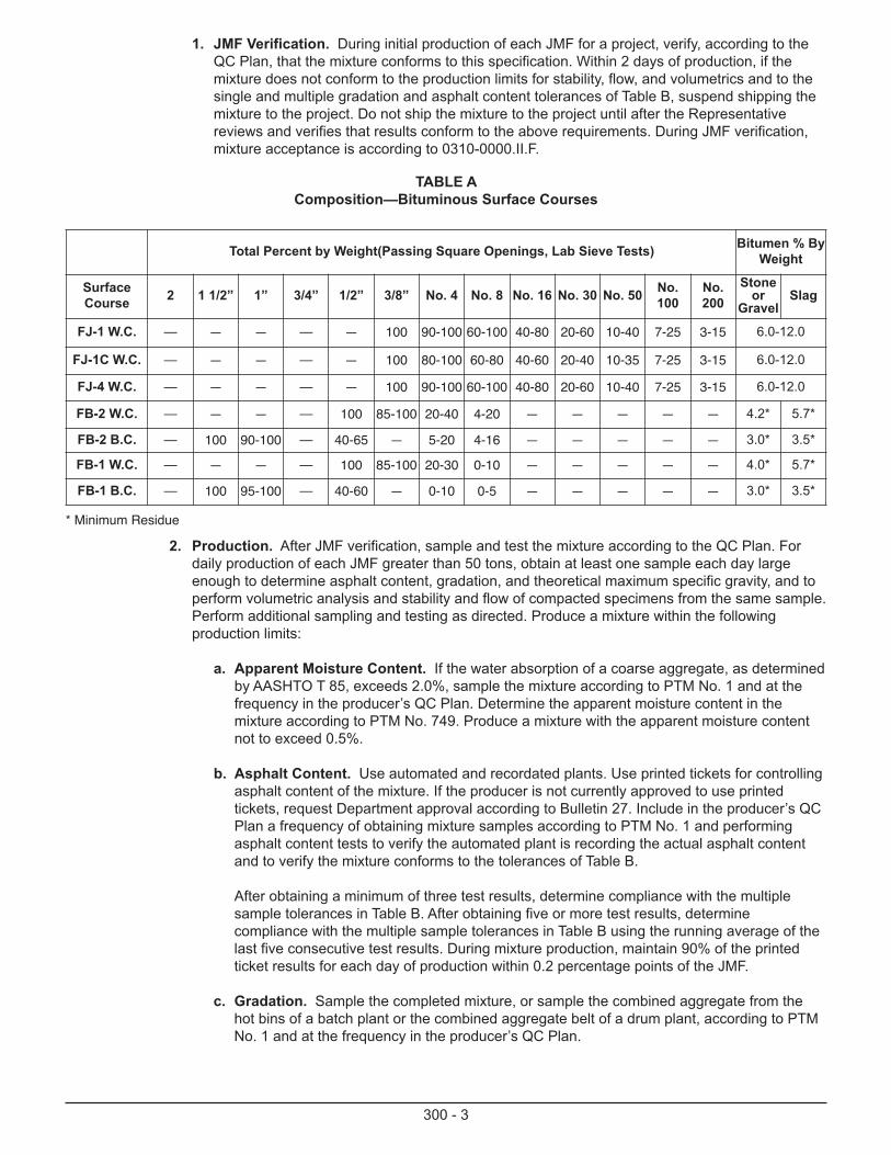
1. JMF Verification. During initial production of each JMF for a project, verify, according to the QC Plan, that the mixture conforms to this specification. Within 2 days of production, if the mixture does not conform to the production limits for stability, flow, and volumetrics and to the single and multiple gradation and asphalt content tolerances of Table B, suspend shipping the mixture to the project. Do not ship the mixture to the project until after the Representative reviews and verifies that results conform to the above requirements. During JMF verification, mixture acceptance is according to 0310-0000.II.F.
Total Percent by Weight(Passing Square Openings, Lab Sieve Tests) Bitumen % ByWeight
SurfaceCourse 2 1 1/2” 1” 3/4” 1/2” 3/8” No. 4 No. 8 No. 16 No. 30 No. 50 No.
100No.200
Stoneor
GravelSlag
FJ-1 W.C. — — — — — 100 90-100 60-100 40-80 20-60 10-40 7-25 3-15 6.0-12.0
FJ-1C W.C. — — — — — 100 80-100 60-80 40-60 20-40 10-35 7-25 3-15 6.0-12.0
FJ-4 W.C. — — — — — 100 90-100 60-100 40-80 20-60 10-40 7-25 3-15 6.0-12.0
FB-2 W.C. — — — — 100 85-100 20-40 4-20 — — — — — 4.2* 5.7*
FB-2 B.C. — 100 90-100 — 40-65 — 5-20 4-16 — — — — — 3.0* 3.5*
FB-1 W.C. — — — — 100 85-100 20-30 0-10 — — — — — 4.0* 5.7*
FB-1 B.C. — 100 95-100 — 40-60 — 0-10 0-5 — — — — — 3.0* 3.5*
TABLE A Composition—Bituminous Surface Courses
* Minimum Residue
2. Production. After JMF verification, sample and test the mixture according to the QC Plan. For daily production of each JMF greater than 50 tons, obtain at least one sample each day large enough to determine asphalt content, gradation, and theoretical maximum specific gravity, and to perform volumetric analysis and stability and flow of compacted specimens from the same sample. Perform additional sampling and testing as directed. Produce a mixture within the following production limits:
a. Apparent Moisture Content. If the water absorption of a coarse aggregate, as determined by AASHTO T 85, exceeds 2.0%, sample the mixture according to PTM No. 1 and at the frequency in the producer’s QC Plan. Determine the apparent moisture content in the mixture according to PTM No. 749. Produce a mixture with the apparent moisture content not to exceed 0.5%.
b. Asphalt Content. Use automated and recordated plants. Use printed tickets for controlling asphalt content of the mixture. If the producer is not currently approved to use printed tickets, request Department approval according to Bulletin 27. Include in the producer’s QC Plan a frequency of obtaining mixture samples according to PTM No. 1 and performing asphalt content tests to verify the automated plant is recording the actual asphalt content and to verify the mixture conforms to the tolerances of Table B.
After obtaining a minimum of three test results, determine compliance with the multiple sample tolerances in Table B. After obtaining five or more test results, determine compliance with the multiple sample tolerances in Table B using the running average of the last five consecutive test results. During mixture production, maintain 90% of the printed ticket results for each day of production within 0.2 percentage points of the JMF.
c. Gradation. Sample the completed mixture, or sample the combined aggregate from the hot bins of a batch plant or the combined aggregate belt of a drum plant, according to PTM No. 1 and at the frequency in the producer’s QC Plan.
300 - 4
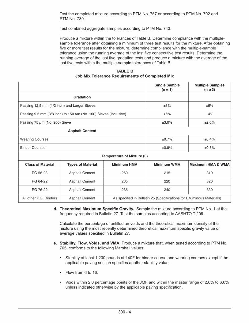
Test the completed mixture according to PTM No. 757 or according to PTM No. 702 and PTM No. 739.
Test combined aggregate samples according to PTM No. 743.
Produce a mixture within the tolerances of Table B. Determine compliance with the multiple-sample tolerance after obtaining a minimum of three test results for the mixture. After obtaining five or more test results for the mixture, determine compliance with the multiple-sample tolerance using the running average of the last five consecutive test results. Determine the running average of the last five gradation tests and produce a mixture with the average of the last five tests within the multiple-sample tolerances of Table B.
TABLE BJob Mix Tolerance Requirements of Completed Mix
Single Sample(n = 1)
Multiple Samples(n ≥ 3)
Gradation
Passing 12.5 mm (1/2 inch) and Larger Sieves ±8% ±6%
Passing 9.5 mm (3/8 inch) to 150 µm (No. 100) Sieves (Inclusive) ±6% ±4%
Passing 75 µm (No. 200) Sieve ±3.0% ±2.0%
Asphalt Content
Wearing Courses ±0.7% ±0.4%
Binder Courses ±0.8% ±0.5%
Temperature of Mixture (F)
Class of Material Types of Material Minimum HMA Minimum WMA Maximum HMA & WMA
PG 58-28 Asphalt Cement 260 215 310
PG 64-22 Asphalt Cement 265 220 320
PG 76-22 Asphalt Cement 285 240 330
All other P.G. Binders Asphalt Cement As specified in Bulletin 25 (Specifications for Bituminous Materials)
d. Theoretical Maximum Specific Gravity. Sample the mixture according to PTM No. 1 at the frequency required in Bulletin 27. Test the samples according to AASHTO T 209.
Calculate the percentage of unfilled air voids and the theoretical maximum density of the mixture using the most recently determined theoretical maximum specific gravity value or average values specified in Bulletin 27.
e. Stability, Flow, Voids, and VMA Produce a mixture that, when tested according to PTM No. 705, conforms to the following Marshall values:
• Stability at least 1,200 pounds at 140F for binder course and wearing courses except if the applicable paving section specifies another stability value.
• Flow from 6 to 16.
• Voids within 2.0 percentage points of the JMF and within the master range of 2.0% to 6.0% unless indicated otherwise by the applicable paving specification.

300 - 5
3. Corrective Actions. Immediately take corrective actions if one or more of the following occurs:
QC test results on a single sample (n=1) for percent passing the No.8 sieve, the No. 200 sieve, or asphalt content are not within the tolerances of Table B.
The average of multiple samples (n≥3) for percent passing any sieve or asphalt content are not within the tolerances of Table B.
QC test results on a single sample (n=1) for stability, flow, voids, VMA, are not within the production tolerances.
Independent Assurance (IA) or QA sample test results at the producer’s plant are not within the tolerances of Table B, or not within the production tolerances for stability, flow, voids, or VMA.
After taking corrective actions, sample the completed mixture within 150 tons of production. After sampling, test the mixture and provide test results to the Representative before shipping additional mixture to the project. If the mixture does not conform to Table B or the production tolerances for stability, flow, or voids suspend production and determine the cause of the problem. Provide a written explanation of the problem and a proposed solution to the Department. After the Representative reviews the proposed solution and authorizes production to continue, resume production and perform JMF verification according to the QC Plan.
2. Mixtures with RAM or RAP. Section 0310-0000.II.E.1. and as follows:
a. RAM and RAP SRL. For HMA wearing courses, limit the total combination of RAM and RAP to a maximum of 15% of the mixture by mass (weight) unless documentation of the SRL designation of the coarse aggregate in the RAM and RAP materials is provided to the DMM/DME and the RAM and RAP conform to the specified SRL or can be blended for SRL as specified in 0310-0000.II.B.
b. RAP Asphalt Content and Gradation. Determine the average asphalt content and gradation of the RAP stockpile according to Bulletin 27. Determine the proportions of RAM, RAP, and virgin materials necessary to conform to the JMF requirements. Maintain and provide the Representative access to records of all sampling, testing, and calculations.
F. Mixture Acceptance.
1. General. The Department will accept the mixture according to certification as specified in Section 0310-0000.II.F.2(b).
2. Certification. Acceptance by certification is appropriate for all mixtures produced in accordance with the Modified Marshal Design Method.
a. General. Obtain certification from the mixture producer. Certify mixtures using Form CS-4171 or another acceptable form. Include the QC test results on the form. Provide the form to the Inspector-in-Charge within 1 working day after completing the QC tests. Certify mixtures as specified in Section 106.03(b)3 and the requirements below.
b. Certification. Certify each mixture daily if QC test results conform to the production limits of 0310-0000.II.E.1(b) and at least 90% of the printed tickets for asphalt content are within 0.2 percentage points of the JMF. If the mixture does not conform to the above requirements, do not certify the mixture. Instead, provide all QC tests results to the Inspector-in-Charge. Payment will be determined according to Pub. 408 Section 409.4(a)3 Table H based on the QC test results. The adjustment for an individual test criterion is the payment factor percentage subtracted from 100%. The total payment factor percentage is the sum of adjustments for each test criterion subtracted from 100%.
c. Maintaining Approval to Certify Mixtures. The Department may suspend certification if QC is not performed according to the producer’s QC Plan, mixtures are not produced according to Bulletin 27, less than 90% of the daily printed ticket results for asphalt content are within 0.2 percentage points of the JMF, or as described below.
300 - 6
The Department may take IA samples of the completed mixture at the plant. In the presence of the Department, test the IA samples for asphalt content and gradation according to the test methods indicated in the producer’s QC Plan. Take immediate corrective actions if the mixture does not conform to Table B.
The Department may take QA samples of the completed mixture at the plant or from directly behind the paver. The Department will test QA samples according to PTM No. 757 for conformance to Table B. If the results of the QA samples do not comply with Table B, review the producer’s QC Plan and the QC test results that followed the QA samples for conformance to Table B.
After completing corrective actions or the sample review, the Department will perform an on-site evaluation of the producer’s plant operation and QC and then take a sample of the completed mixture at the plant. In the presence of the Representative, test the sample. If the sample does not comply with Table B, the Department will suspend certification. Immediately suspend shipping mixtures accepted by certification to the project.
After testing verifies that the produced mixture conforms to Table B, with the Department present, conduct JMF verification according to the QC Plan. After successfully completing JMF verification, resume both certification and shipping mixtures accepted by certification to the project.
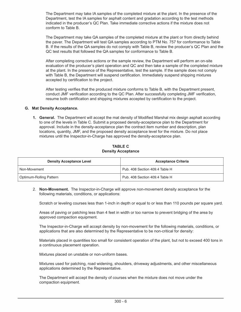
G. Mat Density Acceptance.
1. General. The Department will accept the mat density of Modified Marshal mix design asphalt according to one of the levels in Table C. Submit a proposed density-acceptance plan to the Department for approval. Include in the density-acceptance plan the contract item number and description, plan locations, quantity, JMF, and the proposed density acceptance level for the mixture. Do not place mixtures until the Inspector-in-Charge has approved the density-acceptance plan.
Density Acceptance Level Acceptance Criteria
Non-Movement Pub. 408 Section 409.4 Table H
Optimum-Rolling Pattern Pub. 408 Section 409.4 Table H
TABLE CDensity Acceptance
2. Non-Movement. The Inspector-in-Charge will approve non-movement density acceptance for the following materials, conditions, or applications:
Scratch or leveling courses less than 1-inch in depth or equal to or less than 110 pounds per square yard.
Areas of paving or patching less than 4 feet in width or too narrow to prevent bridging of the area by approved compaction equipment.
The Inspector-in-Charge will accept density by non-movement for the following materials, conditions, or applications that are also determined by the Representative to be non-critical for density:
Materials placed in quantities too small for consistent operation of the plant, but not to exceed 400 tons in a continuous placement operation.
Mixtures placed on unstable or non-uniform bases.
Mixtures used for patching, road widening, shoulders, driveway adjustments, and other miscellaneous applications determined by the Representative.
The Department will accept the density of courses when the mixture does not move under the compaction equipment.

300 - 7
3. Optimum-Rolling Pattern. The Representative will accept density using an optimum-rolling pattern for all materials, except those noted in 707.1(d)2 Non-Movement and as approved by the Representative:
With the Inspector and the Contractor’s certified HMA field technician present, determine density according to ASTM D 2950 with a licensed nuclear gauge operator, or determine density according to PTM No. 403, and follow the control strip technique specified in PTM No. 402, to construct at least one control strip to establish the optimum-rolling pattern for each course. Compact the course according to the optimum-rolling pattern. During paving, the Representative may require the Contractor to construct a new control strip to verify the optimum-rolling pattern.
Use one of the following gauges or approved equal:
Troxler Electronic Laboratories, Model 4640-BCampbell Pacific Nuclear, Model MC-2Seaman Nuclear, Model MC-2TransTech Systems, Inc., PQITM, Model 300 or 301Troxler Electronic Laboratories, PaveTrackerTM
If requested by the Inspector, submit a copy of the certificate of nuclear gage annual calibration according to ASTM D 2950 and documentation of training of the nuclear gage operator. Recalibrate nuclear gauges that are damaged or repaired.
III. CONSTRUCTION
A. Paving Operation QC Plan. Prepare a paving operation QC Plan, as outlined on Form CS-409, for field control and evaluation of bituminous concrete paving operations for the Representative’s review. Submit the QC Plan before or at the pre-construction conference. The QC Plan shall describe the construction equipment and methods necessary to construct and test the bituminous concrete courses as specified in Pub. 447 Section 0310 II. Do not start paving until after the Representative reviews the QC Plan.
B. Weather Limitations. Do not place bituminous paving mixtures from November 1 to March 31, unless allowed in writing by the District Executive. Do not place bituminous paving mixtures when surfaces are wet or when the air or surface temperature is 40F or lower. If work is halted because of weather conditions, the Representative may allow the Contractor to place limited quantities of mixture that are en route to the project.
C. Bituminous Mixing Plant. Obtain bituminous mixtures from a plant fully automated and recordated and currently listed in Bulletin 41. The necessary facilities for inspection include a plant office as specified in Pub. 408 Section 714.5(a), except the minimum floor space is 120 square feet. For recycled mixtures, add the following requirements:
1. Batch Plant. Modify the batch plant to measure the mass (weight) of the RAP before adding it into the pug mill. Design the cold-feed bin, conveyor system, charging chute(s), and all special bins to prevent RAP from segregating and sticking. Dry the virgin aggregate and RAM and then heat the virgin aggregate and RAM to a temperature that, after adding RAP, produces a completed mixture temperature from 260F to 310F. Ensure that virgin aggregate is free of unburned fuel oil when delivered to the pug mill.
2. Drum Mixer Plant. Modify the drum mixer plant to prevent RAP from directly contacting the burner flame and prevent RAP from overheating. Produce a completed mixture with a temperature from 260F to 310F.
D. Hauling Equipment. Haul the mixtures in tightly sealed vehicles that do not contain petroleum oils, solvents, or other materials that adversely affect bituminous concrete. Provide covers of sufficient size and quality to protect the entire load, under all conditions. Maintain the proper and uniform placement temperature specified in Section 0310-0000.III.H.1.a. Provide insulation on all sides of the truck body, a double-walled truck body, or a heated truck body when the air temperature is below 50F between October 1 and May 1.
E. Bituminous Pavers. Provide self-contained, power-propelled units with activated screeds or activated strike-off assemblies and with automatic screed controls, capable of producing a finished surface of specified evenness and texture. Provide heated units capable of spreading and finishing the mixture to the widths and depths indicated. Provide units capable of being operated at forward speeds consistent with satisfactory
300 - 8
laying of the mixture, equipped with receiving hoppers having sufficient capacity for uniform spreading, and equipped with distribution systems that place the mixture uniformly in front of the screeds.
Use hydraulic or other extension types against abutting lanes or longitudinal joints only if the unit feeds and activates the extension by the same method as the main screed. At the outside edge of pavement widths that cannot be uniformly placed, the Contractor may use a non-activated extension when approved by the Inspector-in-Charge.
Do not use equipment that tears, shoves, or gouges the mixture or that causes tracks, indented areas, flushing, or other permanent blemishes. Do not use blade graders or drags.
F. Rollers. Use steel wheel, pneumatic tire, or vibratory rollers as specified in Pub. 408 Section 108.05(c)3. Operate rollers according to manufacturer's recommendations. Use vibratory rollers with separate controls for vibration and propulsion.
G. Preparation of Existing Surface.
1. Conditioning of Existing Surface. Before delivering bituminous mixtures, remove and dispose of loose and foreign material and excess joint sealer and crack filler from the surface of existing pavement or previously placed pavement courses. If necessary, use a broom.
Before placing a wearing course, correct irregularities in the binder course. If practical, do not allow traffic on the binder course to prevent contamination. Remove and replace binder course that cannot be cleaned to the Representative’s satisfaction.
Paint existing vertical surfaces of curbs, structures, gutters, and pavements that will be in contact with bituminous mixtures with a uniform coating of bituminous material, AASHTO SS-1 or CSS-1, AASHTO SS-1h or CSS-1h, Class AET applied in two or more applications, or of the class and type designated for the bituminous course.
Before overlaying existing surfaces, apply a tack coat as specified in Pub.408 Section 460.3 unless otherwise indicated. Apply a tack coat to previously placed courses if the Representative determines a tack coat is necessary to ensure bonding between the two courses.
2. Scratch and Leveling Courses. Where indicated, place a separate scratch or leveling course ahead of resurfacing operations. Use the scratch course to fill wheel ruts and other local small depressions even with the surrounding pavement. Use the leveling course to provide a relatively uniform working platform for placing binder or wearing courses.
H. Spreading and Finishing. Provide a certified HMA field technician with qualifications outlined in Publication 351 and dedicated to controlling the placement of bituminous mixtures. Instruct and train the certified HMA field technician to control the paving operation so that the completed paving work complies with the specified requirements. All certified HMA field technicians must carry a valid certification card during placement of all bituminous mixtures.
1. General Requirements.
a Placing. Unless otherwise allowed, deliver, place, and compact bituminous paving mixtures during daylight hours. Ensure the mixture does not contain lumps of cold material.
Deliver and place virgin-material mixtures at the laying temperatures specified in Table B for the type and class of material used.
b Spreading and Finishing. Spread and strike off the mixture over the entire lane width or as much lane width as practical. Adjust screed assemblies to provide the required cross section and depth. After spreading, do not add mixture to the pavement mat that is segregated or below the minimum temperature, contains either a deficiency or an excess of asphalt content, or is otherwise unsuitable to add to the pavement mat.
300 - 9
If the course is more than 6 inches in compacted depth, construct it in two or more layers of approximately equal depth, with no layer less than 3 inches or more than 6 inches in compacted depth. For binder or leveling courses that have isolated areas exceeding 6-inch compacted depth, use a scratch or leveling course to eliminate the isolated areas before full-depth paving.
Immediately after placing the bituminous mixture, work the exposed outer edges to avoid a sharp, ragged, and open edges; to eliminate an unfinished appearance; and to reduce edge breakdown. Immediately repair edge breakdowns.
In areas where mechanical spreaders cannot be used, place and screed the mixture with suitable hand tools. Do not use rakes.
Adjacent to flush curbs, gutters, and other abutting structures, place the wearing course mixture uniformly higher so that after compaction the finished surface is slightly above the edge of the abutting structure. Remove harmful material, clean, and seal the surface of wearing courses adjacent to curbs to form a bituminous gutter. Seal the mixture surface with bituminous material of the class and type designated for the wearing course. Evenly apply the bituminous material a minimum width of 12 inches from the curb. The Contractor may use Class AET, Class AASHTO SS-1 or CSS-1, or AASHTO SS-1h or CSS-1h emulsified asphalt instead of hot bituminous material. Control the application rate so residual asphalt completely fills surface voids and provides a watertight joint along the curb. If necessary, apply emulsified asphalt in two or more applications. After sealing, remove excess sealant material.
2. Pattern Segregation. Pattern segregation is continuous or repeated areas of non-uniform distribution of coarse and fine aggregate particles in the finished mat. The Department will address pattern segregation as follows:
a Evaluation of Pattern Segregation. If the Representative observes pattern segregation that may result in defective pavement, then:
The Inspector will immediately notify the Contractor of the observed pattern segregation.
The Contractor may continue work at its own risk and immediately and continually adjust the operation and eliminate the pattern segregation from future work.
As a minimum and in the presence of the Representative, determine the average depth of pavement surface macrotexture of areas with the pattern segregation and areas with non-segregated pavement according to PTM No. 751. The pattern segregation is unacceptable if the difference in pavement texture depth between the non-segregated and segregated areas exceeds 0.610 mm (0.024 inch). The Representative will determine the extent of defective pavement as specified in 409.3(h)3.c.
b Test Section. If the macrotexture tests identify unacceptable pattern segregation, then:
Immediately suspend placement of the bituminous course. Evaluate the cause of pattern segregation according to the Paving Operation QC Plan and as directed. Provide proposed corrective actions to the Representative. Do not resume placing the bituminous course until after the Representative has reviewed the proposed corrective actions.
After the Representative allows paving to resume, place a test section not to exceed 200 tons. If the corrective actions do not eliminate unacceptable pattern segregation, the Department will suspend paving before the Contractor places the entire test section. Determine if the pattern segregation resulted in defective pavement as specified in Section 0310-0000.III.H.2.c, propose additional corrective actions, and construct another test section. Resume normal paving operations after constructing an entire test section without the Representative observing pattern segregation.
c Defective Pavement. At locations selected by the Inspector and with the Inspector present, drill a minimum of three 6-inch diameter cores from both the area of pattern segregation and the pavement representing non-segregated areas. Do not compress, bend, or distort samples during cutting and handling and immediately provide the cores to the Inspector. The Inspector will transport cores to the

300 - 10
plant. With the Inspector present, test the cores at the plant for density, extraction, and gradation analysis. The Department may request additional tests as part of its evaluation of pattern segregation. Determine the maximum theoretical density according to AASHTO T 209 and core density according to PTM No. 715.
An area of pattern segregation contains defective pavement if two or more sieves vary 10% or more from the JMF, the summation of deviations from any two sieves is 20% or more from the JMF, the core density is defective, the mixture is defective in asphalt content, or the mixture is defective forpercent passing the 75 m (No. 200) sieve. Remove and replace the full width of the affected lane and a minimum of 5 feet beyond each end of the area with unacceptable pattern segregation. For replacement, use the appropriate surface tolerances as specified in Section 0310-0000.III.L.
I. Compaction. Compact the mixture to achieve the density acceptance requirements and to eliminate all roller marks. Compact the mixture while it is in proper condition and adjust roller speed, amplitude, frequency, pattern, and roller size to eliminate displacement, shoving, cracking, and aggregate breakage. Satisfactorily correct displacement resulting from reversing roller directions and other causes.
Without using excess water, maintain wheels of steel wheel rollers moist and clean to prevent the mixture from adhering to the wheels. Use suitable methods to clean pneumatic tire roller wheels.
For areas inaccessible to rollers, compact with mechanical vibrating hand tampers.
Remove areas that are loose, broken, mixed with dirt, or show an excess or deficiency of bituminous material. Replace removed mixture with fresh hot mixture and compact the mixture even with the surrounding pavement surface.
J. Joints.
1. Longitudinal Joints.
a General. Offset joints in a layer from the joint in the layer immediately below by approximately 6 inches. Plan joint locations to ensure the joint in the top layer is at the approximate pavement centerline for two-lane roadways and within 12 inches of the lane lines for roadways with more than two lanes.
Before placing abutting lanes, paint the entire area of the joint with a thin coating of bituminous material, Class AET, Class AASHTO SS-1 or CSS-1, AASHTO SS-1h or CSS-1h, or PG 64-22. Use two applications of AET emulsified asphalt.
Place and compact the mixture at the joint according to the Paving Operation QC Plan. Ensure the surface across the joint is smooth and the surface along the joint is within the surface tolerances specified in Section 0310-0000.III.K.
If traffic or other causes distort the lane edge, restore the land edge to its original shape using acceptable procedures.
b Vertical Joints.
The Contractor may use vertical joints for base, binder, and wearing courses.
If traffic or other cause distorts the lane edge, carefully saw a vertical lane edge before painting.
Place the abutting lane on the same day, and if necessary, leave only short lane sections, normally less than 25 feet, where the abutting lane is not placed the same day.
c Notched Wedge Joints.
The Contractor can use notched wedge joints for wearing and binder courses.
300 - 11
Remove and dispose of all loose and foreign material before opening the lane to traffic.
Construct the joint according to Standard Drawing RC-28.
If the joint is next to opposing traffic, place the abutting lane within 1 working day after placing the mixture. If the joint is next to traffic in the same direction, place the abutting lane within 10 working days after placing the mixture.
If both lanes that make the joint are not placed on the same day, amend the Maintenance andProtection of Traffic Plan and install additional signing for uneven pavements at no additional cost to the Department. Install “Uneven Pavement” signs according to Publication 212 and 1/2-mile before the notched wedge joint area and every 1/2-mile within the uneven pavement area.
2. Transverse Joints. Construct joints perpendicular to the pavement surface. The Contractor may saw transverse joints. If used, install bulkheads straight and perpendicular to the surface. If bulkheads are not used and the roller moves over the rounded edge of new mixture, locate the joint a sufficient distance from the rounded edge to provide a true surface and cross section. Paint the joint face with a thin coating of bituminous material, Class AET, Class AASHTO SS-1 or CSS-1, AASHTO SS-1h or CSS-1h, or PG 64-22, before placing fresh mixture against the joint face. If necessary, use two applications of AET emulsified asphalt.
3. Other Joints. Where placing a wearing course abutting to existing pavement at locations such as paving notches, lane additions, or utility openings, seal the joint with hot bituminous material of the class and type designated for the wearing course. Evenly apply the sealant a minimum of 6 inches on both sides of the joint. The Contractor may use a Class AET, Class AASHTO SS-1 or CSS-1 or AASHTO SS-1h or CSS-1h emulsified asphalt instead of hot bituminous material. Before sealing, clean and remove harmful material from the area to be sealed. Control the application rate so residual asphalt completely fills surface voids and provides a watertight joint. If necessary, use two or more applications of emulsified asphalt. Remove excess bituminous material and immediately cover the sealed area with a light application of acceptable dry sand.
K. Surface Tolerance. Test the finished surface with a 10-foot straightedge at areas the Representative determines may be deficient or irregular, and at transverse joints and paving notches, and at longitudinal joints. Hold the straightedge in contact with the surface and in successive positions parallel to the road centerline to check the entire width of the pavement. Advance along the pavement in stages of not more than one half the length of the straightedge until the entire area is tested. The pavement is defective if irregularities are more than 3/16 inch. View Animation.
L. Tests for Depth: Binder and Wearing Courses. Construct the pavement to the depth indicated and within the specified tolerances.
For courses with a designed course depth and density acceptance by non-movement or rolling pattern, the Inspector will calculate the mass per square meter (weight per square yard) for verification of yield. If yield results indicate insufficient course depth, drill one 6 inch diameter core for each 200 tons to determine the extent of pavement with deficient depth. Pavement deficient in depth by more than 1/4 inch and that cannot be satisfactorily corrected is defective. Pavement deficient by more than 1/8 inch in three adjacent core locations and that cannot be satisfactorily corrected is defective. After the Inspector completes depth measurements, backfill, compact, and seal core holes with the mixture used to construct the course. Immediately start correction of courses deficient in depth at the core location and proceed longitudinally and transversely until the depth is within 1/4 inch of the design depth.
M. Protection of Courses. Do not allow vehicular traffic or loads on newly compacted courses for 24 hours or until the mixture uniformly cools to a temperature of 140F or less. Provide alternate routes as indicated or as directed. If both lanes that form a longitudinal joint are placed on the same day and public safety is not restricted, do not allow vehicular traffic or loads on the lanes until adequate stability and adhesion are obtained and the material has uniformly cooled to 140F or less. Maintain the course, as specified in Pub. 408 Sections 105.13, 107.15, and 901.

300 - 12
N. Defective Work. As specified in Pub. 408 Section 105.12 and as follows:
Department acceptance and QA testing shall not relieve the Contractor of responsibility for material or work quality that the Representative determines is defective before the Department issues the acceptance certificate. Remove and replace, or repair defective work as directed. The LTS will review Representative determinations of defective materials or work quality.
Unless otherwise directed in writing by the District Executive remove and replace defective pavement for surface tolerance as specified in Section 0310-0000.III.K, depth as specified in Section 0310-0000.III.L, and pattern segregation as specified in Section 0310-0000.III.H.
300 - 13
MS-0310-0010FB-Modified Bituminous Paving Course
I. DESCRIPTION - This work is construction of a binder or wearing course of plant mixed bituminous concrete,using modified asphalt cement, on a prepared surface .
II. MATERIAL- FB-Modified is a dense graded Cold Mix which is a combination base and wearing course in onematerial. FB-Modified is typically selected for low volume roads which have a deficient base and are severelydeteriorated where a flexible material is required .
A. Bituminous Material. Modify or use appropriate modifiers, if necessary, to obtain a mix which results in a pavement meeting the performance criteria specified in Sections lll(A) 2, and 111(0) and which does not exceed 12% oil distillate by volume of the total bituminous binder material when tested in accordance with the procedure specified in, Section C. The base bituminous material shall meet the requirements of standardspecification for performance graded asphalt binder, AASHTO M 320 except as revised in Department Bulletin 25.
B. Aggregates.
Fine Aggregates - Publication 408, Section 703.1. Determine sand equivalent value in accordance with AASHTO T176, if applicable. Minimum sand equivalent value = 40%
Coarse Aggregate - Type A, Publication 408, Section 703.2. Minimum 75% crushed fragments in accordance with PTM No. 621.
C. Composition of Mixture. Test the completed mixture, sampled within 30 seconds of discharge at the plant and placed in a sealed container in accordance with AASHTO T_59, Sections 9 thru 13; however, modify the procedure outlined in Section 12 by weighing 850 grams (30 ounces) of a representative sample of the mixture and 50 ml (1.7 ounces) of distilled water in the previously weighed aluminum-alloy still (includinglid, clamp, thermometers and gaskets, if gasket is used). This test method will be used for quantitative determination of the percentage of oil distillates in the bituminous mixture by using a ratio of the volume of oil distillate (ml) to the total volume of bituminous binder material (ml) including residual asphalt cement, oil distillates, and water, excluding the 50 ml added for testing. The oil distillate obtained using this test method can be further tested employing qualitative analysis such as gas chromatography (GC) or gaschromatography-mass spectrometry (GC-MS).
1. Uniformity. Perform tests for bitumen content and aggregate gradation as established in the quality control plan and in accordance with PTM No. I.
2. Acceptance of the Mixture. Obtain material certification from the material producer as specified in Publication 408, Section 106.03(b) 3.
Certify using a Department form CS-41718 (Latest Version). Send certification to the Inspector-in-Charge within oneworking day following quality control tests for bitumen content determination and sieve analysis of the mixture.
300 - 14
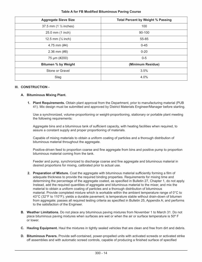
Table A for FB Modified Bituminous Paving Course
Aggregate Sieve Size Total Percent by Weight % Passing
37.5 mm (1 ½ inches) 100
25.0 mm (1 inch) 90-100
12.5 mm (½ inch) 55-85
4.75 mm (#4) 0-45
2.36 mm (#8) 0-20
75 μm (#200) 0-5
Bitumen % by Weight (Minimum Residue)
Stone or Gravel 3.5%
Slag 4.0%
Ill. CONSTRUCTION -
A. Bituminous Mixing Plant.
1. Plant Requirements. Obtain plant approval from the Department, prior to manufacturing material (PUB 41). Mix design must be submitted and approved by District Materials Engineer/Manager before starting.
Use a synchronized, volume-proportioning or weight-proportioning, stationary or portable plant meeting the following requirements:
Aggregate bins and a bituminous tank of sufficient capacity, with heating facilities when required, to assure a constant supply and proper proportioning of materials.
Capable of mixing materials to obtain a uniform coating of particles and a thorough distribution of bituminous material throughout the aggregate.
Positive-driven feed to proportion coarse and fine aggregate from bins and positive pump to proportion bituminous material coming from the tank.
Feeder and pump, synchronized to discharge coarse and fine aggregate and bituminous material in desired proportions for mixing, calibrated prior to actual use.
2. Preparation of Mixture. Coat the aggregate with bituminous material sufficiently forming a film of adequate thickness to provide the required binding properties. Requirements for mixing time and determining the percentage of the aggregate coated, as specified in Bulletin 27, Chapter 1, do not apply. Instead, add the required quantities of aggregate and bituminous material to the mixer, and mix the material to obtain a uniform coating of particles and a thorough distribution of bituminousmaterial. Provide completed mixture which is workable within the ambient temperature range of 0°C to 43°C (32°F to 110°F); yields a durable pavement; is temperature stable without drain-down of bitumen from aggregate; passes all required testing criteria as specified in Bulletin 25, Appendix A; and performs to the satisfaction of the Engineer.
B. Weather Limitations. Do not place any bituminous paving mixtures from November 1 to March 31. Do not place bituminous paving mixtures when surfaces are wet or when the air or surface temperature is 50º F or lower.
C. Hauling Equipment. Haul the mixtures in tightly sealed vehicles that are clean and free from dirt and debris.
D. Bituminous Pavers. Provide self-contained, power-propelled units with activated screeds or activated strike off assemblies and with automatic screed controls, capable of producing a finished surface of specified
evenness and texture. Provide heated units (unless the bituminous material used is emulsified asphalt) capable of spreading and finishing the mixture to the widths and depths indicated. Provide units capable of being operated at forward speeds consistent with satisfactory placement of the mixture, equipped with receiving hoppers having sufficient capacity for uniform spreading and equipped with distribution systems that place the mixture uniformly in front of the screed. Do not use equipment that tears, shoves, or gouges the mixture, or that causes tracks, indented areas, flushing, segregation, or other permanent blemishes.
E. Rollers. Use a steel drum asphalt roller having a mass of not less than 8 Tons. The use of a pneumatic-tire roller is not required but may be used if approved by the Engineer.
F. Preparation of Existing Surfac . Before delivering bituminous mixtures, remove and dispose of loose and foreign material from the surface of existing pavement or previously placed pavement courses. If necessary , use a broom. Install Paving Notches by milling existing pavement surface at tie-in locations, only when designated in contract. Install Tack Coat in accordance with Section 460, apply only when designated in the contract. Install Bituminous Prime Coat in accordance with Section 461, apply only when designated in the contract.
G. Placement. Spread courses to the loose depth needed to obtain the required compacted depth. Spread and strike off the mixture using mechanical equipment for the entire lane width or as much lane as may be practical. Adjust screed assemblies to provide the required cross section and depth.
H. Compaction. After the courses, have been spread uniformly, compact with a power roller until the mixture is compressed to a firm, even surface. Intermediate rolling with a pneumatic-tire roller is not required, but may be used if approved by the Engineer. Roll the surface when the mixture is in proper condition and when rolling will not cause undue displacement, cracking, or shoving. Use suitable rollers, roller combinations, and rollingpatterns to provide required compaction. Continuously roll until the specified compaction is obtained and roller marks are eliminated. Operate rollers slowly enough to avoid displacement of mixture and satisfactorily correct displacement resulting from reversing roller direction or from other causes.
I. Density Acceptance. Density acceptance will be determined based on non-movement of material under compaction equipment. Use roller pattern as per QA plan.
J. Joints. When compacting the joint, shift the static steel-wheel roller onto the previously placed lane so only (1 or 2 inches) of the drive wheel extends over the uncompacted material. Continue to roll along this line, shifting position gradually across the joint until the joint has been rolled with the entire width of the drive wheel. Roll with steel-wheel and pneumatic-tire rollers until a thoroughly compacted neat joint is obtained.
K. Surface Tolerance. Test the finished surface with a 10-foot straightedge at areas the Representative determines may be deficient or irregular, and at transverse joints and paving notches. Hold the straightedge incontact with the surface and in successive positions parallel to the road centerline to check the entire width of the pavement. Advance along the pavement in stages of not more than one-half the length of the straightedge until the entire area is tested. The pavement is defective if irregularities are more than 1 /2 inch.
L. Test for Depth. Construct the pavement to the depth indicated and within the specified tolerances.
M. Protection of Courses. Do not allow vehicular traffic or loads on newly compacted courses until adequate stability is obtained. Provide alternate routes as indicated or directed. If required or necessary, while the surface is still tacky and before opening to traffic, uniformly spread a layer of fine aggregate on the surface at a rate of (3 to 5 pounds per square yard). Sweep and roll, as directed.
N. Defective Work. Unless otherwise directed in writing by the Representative, remove and replace pavement deficient in compaction as specified above in Section Ill. I., or surface tolerance as specified above in Section 111K., or depth where applicable as specified above in Section Ill. L., or residual asphalt content as specified above in Section II. C.2.
O. General Performance. Provide completed pavement which performs to the satisfaction of the Representative without bleeding, rutting, pushing, shoving, raveling, stripping, or showing other types of pavement distress or unsatisfactory performance. Remove and replace unsatisfactory material at no additional cost to the Department.
300 - 15
IV. MEASUREMENT AND PAYMENT
A. FB Modified Bituminous Paving Course . Square Yard or Ton.
Square Yard Measurement and Payment. Square Yard Measurement and payment using calibrated/accepted lineal instruments acceptable to Customer.
Ton Measurement and Payment. Portable Plants meet the following requirements.
1) Inspected and Calibrated annually by Department per Section 111A .
2) Weighing devices calibrated when plant is moved and set up.
3) Tons produced are determined by adding the weight of aggregate weighed plus bitumen.
4) Form CS-4171 B (Latest Version) Certificate of Compliance furnished as requested.
300 - 16

300 - 17
MS-0310-0011FB-3 Modified Bituminous Wearing Course
I. DESCRIPTION - This work is construction of a wearing course of plant mixed bituminous concrete, using modified asphalt cement, on a prepared surface.
II. MATERIAL - Publication 408, Section 409.2, modified as shown below.
A. Bituminous Material.
Modify or use appropriate modifiers, if necessary, to obtain a mix which results in a pavement meeting the performance criteria specified in Sections lll(A) 2, and Ill (J) and which does not exceed 12% oil distillate by volume of the total bituminous binder material when tested in accordance with the procedure specified in, Section C. The base bituminous material shall meet the requirements of standard specification for performance graded asphalt binder, AASHTO MP-I except as revised in Department Bulletin 25.
B. Aggregates.
Fine Aggregates - Publication 408, Section 703.1. Determine sand equivalent value in accordancewith AASHTO T176, if applicable. Minimum sand equivalent value 40%
Coarse Aggregate - Type A, Publication 408, Section 703.2. Minimum 75% crushed fragments in accordance with PTM No. 621.
C. Composition of Mixture.
Test the completed mixture, sampled within 30 seconds of discharge at the plant and placed in a sealed container in accordance with AASHTO-TS9, Sections 9 thru 13; however, modify the procedure outlined in Section 12 by weighing 850 grams (30 ounces) of a representative sample of the mixture and 50 ml (1.7 ounces) of distilled water in the previously weighed aluminum-alloy still (including lid, clamp, thermometers and gaskets, if gasket is used). This test method will be used for quantitative determination of the percentage of oil distillates in the bituminous mixture by using a ratio of the volume of oil distillate (ml) to the total volume of bituminous binder material (ml) including residual asphalt cement, oil distillates, and water, excluding the 50 ml added for testing. The oil distillate obtained using this test method can be further tested employing qualitative analysis such as gas chromatography (GC) or gas chromatography-mass spectrometry (GC-MS).
1. Uniformity. Perform tests for bitumen content and aggregate gradation as established in the quality control plan and in accordance with PTM No. I.
2. Acceptance of the Mixture.
Obtain material certification from the material producer as specified in Publication 408, Section 106.03(b) 3.
Certify using a Department form CS-4171. Send certification to the Inspector-in-Charge within one working day following quality control tests for bitumen content determination and sieve analysis ofthe mixture.
300 - 18
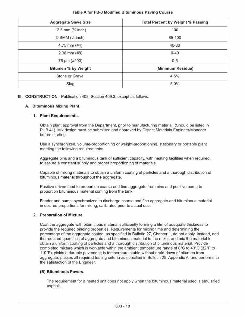
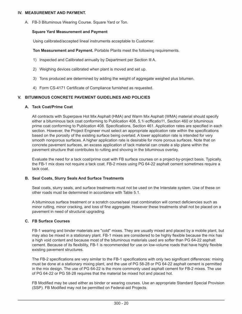
Ill. CONSTRUCTION - Publication 408, Section 409.3, except as follows:
A. Bituminous Mixing Plant.
1. Plant Requirements.
Obtain plant approval from the Department, prior to manufacturing material. (Should be listed inPUB 41). Mix design must be submitted and approved by District Materials Engineer/Managerbefore starting.
Use a synchronized, volume-proportioning or weight-proportioning, stationary or portable plantmeeting the following requirements:
Aggregate bins and a bituminous tank of sufficient capacity, with heating facilities when required,to assure a constant supply and proper proportioning of materials.
Capable of mixing materials to obtain a uniform coating of particles and a thorough distribution ofbituminous material throughout the aggregate.
Positive-driven feed to proportion coarse and fine aggregate from bins and positive pump toproportion bituminous material coming from the tank.
Feeder and pump, synchronized to discharge coarse and fine aggregate and bituminous materialin desired proportions for mixing, calibrated prior to actual use.
2. Preparation of Mixture.
Coat the aggregate with bituminous material sufficiently forming a film of adequate thickness toprovide the required binding properties. Requirements for mixing time and determining thepercentage of the aggregate coated, as specified in Bulletin 27, Chapter 1, do not apply. Instead, addthe required quantities of aggregate and bituminous material to the mixer, and mix the material toobtain a uniform coating of particles and a thorough distribution of bituminous material. Providecompleted mixture which is workable within the ambient temperature range of 0°C to 43°C (32°F to110°F); yields a durable pavement; is temperature stable without drain-down of bitumen fromaggregate; passes all required testing criteria as specified in Bulletin 25, Appendix A; and performs tothe satisfaction of the Engineer.
(B) Bituminous Pavers.
The requirement for a heated unit does not apply when the bituminous material used is emulsified asphalt.
Table A for FB-3 Modified Bituminous Paving Course
Aggregate Sieve Size Total Percent by Weight % Passing
12.5 mm (½ inch) 100
9.SMM (½ inch) 85-100
4.75 mm (#4) 40-80
2.36 mm (#8) 0-40
75 μm (#200) 0-5
Bitumen % by Weight (Minimum Residue)
Stone or Gravel 4.5%
Slag 5.0%
300 - 19
(C) Preparation of Existing Surface.
Tack coat requirements apply only when designated in the contract.
(D) Spreading and Finishing.
Spread courses to the loose depth needed to obtain the required compacted depth. Spreadand strike off the mixture using mechanical equipment for the entire lane width or as muchlane as may be practical. Adjust screed assemblies to provide the required cross section anddepth.
(E) Compaction.
After the courses, have been spread uniformly, compact with a power roller until the mixture iscompressed to a firm, even surface. Intermediate rolling with a pneumatic-tire roller is notrequired, but may be used if approved by the Engineer. Roll the surface when the mixture is inproper condition and when rolling will not cause undue displacement, cracking, or shoving. Usesuitable rollers, roller combinations, and rolling patterns to provide required compaction.Continuously roll until the specified compaction is obtained and roller marks are eliminated.Operate rollers slowly enough to avoid displacement of mixture and satisfactorily correctdisplacement resulting from reversing roller direction or from other causes.
(F) Density Acceptance.
Density acceptance will be determined based on non-movement of material under compactionequipment.
(G) Joints.
When compacting the joint, shift the static steel-wheel roller onto the previously placed lane soonly (1 or 2 inches) of the drive wheel extends over the uncompacted material. Continue to rollalong this line, shifting position gradually across the joint until the joint has been rolled with theentire width of the drive wheel. Roll with steel-wheel and pneumatic-tire rollers until athoroughly compacted neat joint is obtained.
(H) Protection of Courses.
If required or necessary, while the surface is still tacky and before opening to traffic, uniformlyspread a layer of fine aggregate on the surface at a rate of 3 to 5 pounds per square yard.Sweep and roll, as directed.
(I) Defective Work.
Unless otherwise directed in writing by the Representative, remove and replace pavementdeficient in compaction as specified in Section 111.E. or surface tolerance as specified in Section409.3 (I), or depth where applicable as specified in Section 409.3 (m), or residual asphalt contentas specified in Section 11.C.2 Table A
(s) General Performance.
Provide completed pavement which performs to the satisfaction of the Representative withoutbleeding, rutting, pushing, shoving, raveling, stripping, or showing other types of pavementdistress or unsatisfactory performance. Remove and replace unsatisfactory material at noadditional cost to the Department.
300 - 20
IV. MEASUREMENT AND PAYMENT.
A. FB-3 Bituminous Wearing Course. Square Yard or Ton.
Square Yard Measurement and Payment
Using calibrated/accepted lineal instruments acceptable to Customer.
Ton Measurement and Payment. Portable Plants meet the following requirements.
1) Inspected and Calibrated annually by Department per Section Ill A.
2) Weighing devices calibrated when plant is moved and set up.
3) Tons produced are determined by adding the weight of aggregate weighed plus bitumen.
4) Form CS-4171 Certificate of Compliance furnished as requested.
V. BITUMINOUS CONCRETE PAVEMENT GUIDELINES AND POLICIES
A. Tack Coat/Prime Coat
All contracts with Superpave Hot Mix Asphalt (HMA) and Warm Mix Asphalt (WMA) material should specify either a bituminous tack coat conforming to Publication 408, 5,1i ecfficatio11, Section 460 or bituminous prime coat conforming to Publication 408. Specifications, Section 461. Application rates are specified in each section. However, the Project Engineer must select an appropriate application rate within the specifications based on the porosity of the existing surface being overlaid. A lower application rate is intended for very smooth nonporous surfaces. A higher application rate is desirable for more porous surfaces. Note that on concrete pavement surfaces, an excess application of tack material can create a slip plane within the pavement structure that contributes to rutting and shoving in the bituminous overlay.
Evaluate the need for a tack coat/prime coat with FB surface courses on a project-by-project basis. Typically, the FB-1 mix does not require a tack coat. FB-2 mixes using PG 64-22 asphalt cement sometimes require a tack coat.
B. Seal Coats, Slurry Seals And Surface Treatments
Seal coats, slurry seals, and surface treatments must not be used on the Interstate system. Use of these on other roads must be determined in accordance with Table 5.1.
A bituminous surface treatment or a scratch course/seal coat combination will correct deficiencies such as minor rutting, minor cracking, and loss of fine aggregate. However these treatments shall not be placed on a pavement in need of structural upgrading.
C. FB Surface Courses
FB-1 wearing and binder materials are "cold" mixes. They are usually mixed and placed by a mobile plant, but may also be mixed in a stationary plant. FB-1 mixes are considered to be highly flexible because the mix has a high void content and because most of the bituminous materials used are softer than PG 64-22 asphalt cement. Because of its flexibility, FB-1 is recommended for use on low-volume roads that have highly flexible existing pavement structures.
The FB-2 specifications are very similar to the FB-1 specifications with only two significant differences: mixing must be done at a stationary mixing plant, and the use of PG 58-28 or PG 64-22 asphalt cement is permitted in the mix design. The use of PG 64-22 is the more commonly used asphalt cement for FB-2 mixes. The use of PG 64-22 or PG 58-28 requires that the material be mixed hot and placed hot.
FB Modified may be used either as binder or wearing courses. Use an appropriate Standard Special Provision (SSP). FB Modified may not be permitted on Federal-aid Projects.
300 - 21
Because of the high void content in the FB-1 and FB-2 surfaces, a seal coat or surface treatment must be placed on the FB surface. A minimum of 3 months of warm weather traffic densification of the FB surface is recommended before the application of either a seal coat or surface treatment. When the underlying pavement is structurally sound and the FB surface is in satisfactory condition, it is possible to postpone these applications up to 3 years. A seal coat or surface treatment may not be required on an FB Modified surface for at least 4 years.
When a deflection-based design program is used for design with FB surfaces, the depth of the FB overlay must be adjusted since the program assumes the overlay material is HMA. A structural coefficient of 0.20 must be used for FB courses when designing FB overlays. See Chapter 9 for the structural coefficients for paving materials.
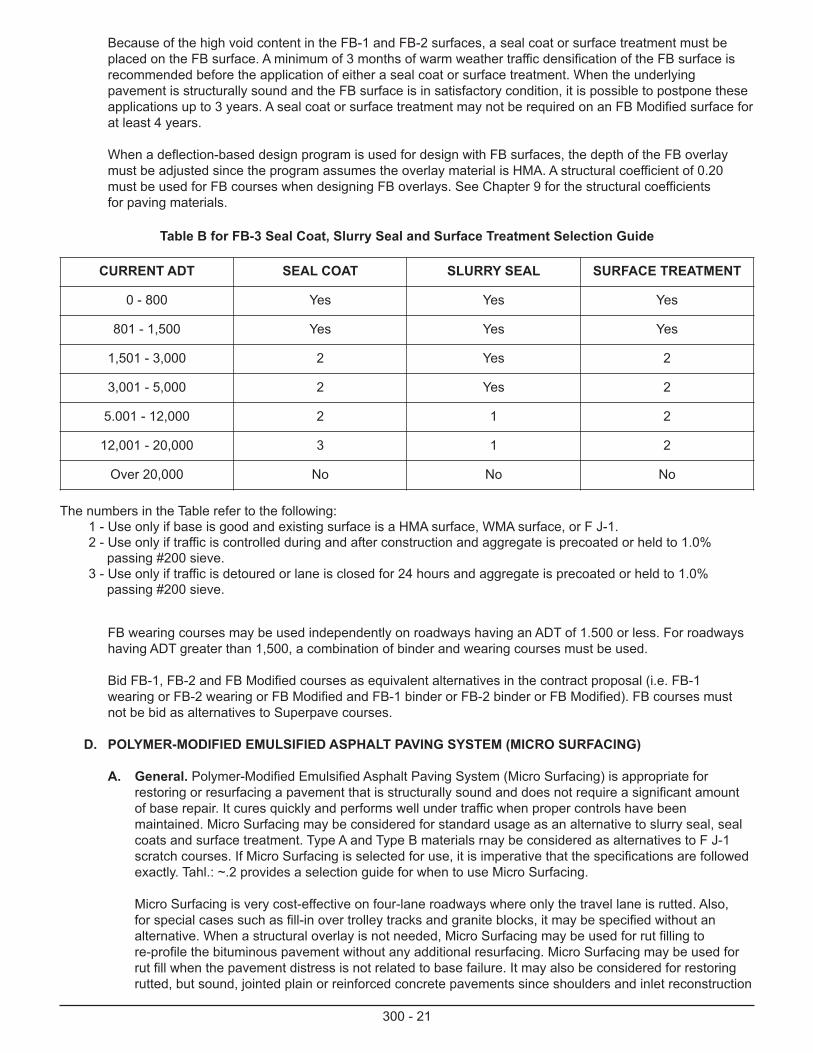
Table B for FB-3 Seal Coat, Slurry Seal and Surface Treatment Selection Guide
CURRENT ADT SEAL COAT SLURRY SEAL SURFACE TREATMENT
0 - 800 Yes Yes Yes
801 - 1,500 Yes Yes Yes
1,501 - 3,000 2 Yes 2
3,001 - 5,000 2 Yes 2
5.001 - 12,000 2 1 2
12,001 - 20,000 3 1 2
Over 20,000 No No No
The numbers in the Table refer to the following:1 - Use only if base is good and existing surface is a HMA surface, WMA surface, or F J-1.2 - Use only if traffic is controlled during and after construction and aggregate is precoated or held to 1.0%
passing #200 sieve.3 - Use only if traffic is detoured or lane is closed for 24 hours and aggregate is precoated or held to 1.0%
passing #200 sieve.
FB wearing courses may be used independently on roadways having an ADT of 1.500 or less. For roadways having ADT greater than 1,500, a combination of binder and wearing courses must be used.
Bid FB-1, FB-2 and FB Modified courses as equivalent alternatives in the contract proposal (i.e. FB-1 wearing or FB-2 wearing or FB Modified and FB-1 binder or FB-2 binder or FB Modified). FB courses must not be bid as alternatives to Superpave courses.
D. POLYMER-MODIFIED EMULSIFIED ASPHALT PAVING SYSTEM (MICRO SURFACING)
A. General. Polymer-Modified Emulsified Asphalt Paving System (Micro Surfacing) is appropriate for restoring or resurfacing a pavement that is structurally sound and does not require a significant amount of base repair. It cures quickly and performs well under traffic when proper controls have been maintained. Micro Surfacing may be considered for standard usage as an alternative to slurry seal, seal coats and surface treatment. Type A and Type B materials rnay be considered as alternatives to F J-1 scratch courses. If Micro Surfacing is selected for use, it is imperative that the specifications are followed exactly. Tahl.: ~.2 provides a selection guide for when to use Micro Surfacing.
Micro Surfacing is very cost-effective on four-lane roadways where only the travel lane is rutted. Also,for special cases such as fill-in over trolley tracks and granite blocks, it may be specified without an alternative. When a structural overlay is not needed, Micro Surfacing may be used for rut filling to re-profile the bituminous pavement without any additional resurfacing. Micro Surfacing may be used for rut fill when the pavement distress is not related to base failure. It may also be considered for restoring rutted, but sound, jointed plain or reinforced concrete pavements since shoulders and inlet reconstruction

300 - 22
can be greatly reduced or eliminated. On Jointed Plain Concrete Pavement (JPCP) and Jointed Reinforced Concrete Pavement (JRCP), do not place Superpave HMA/WMA scratch and/or levelingcourse prior to application of Micro Surfacing. In addition, Micro Surfacing can be effectively used to restore skid resistance to otherwise structurally sound pavements.
300 - 23
MS-0310-0021BITUMINOUS WEARING COURSE FB 2
I. DESCRIPTION—This work is construction of a wearing course of plant mixed bituminous concrete on a prepared surface.
II. MATERIAL—MS-0310-0000. II with the following modifications:
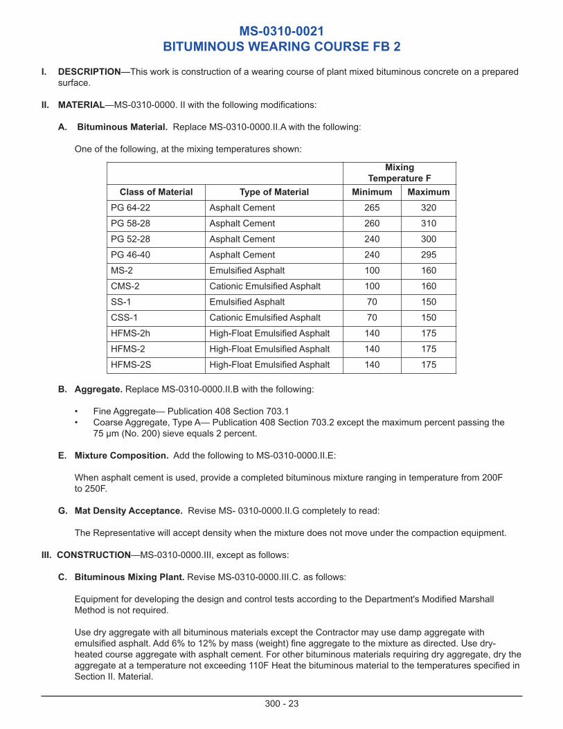
A. Bituminous Material. Replace MS-0310-0000.II.A with the following:
One of the following, at the mixing temperatures shown:
MixingTemperature F
Class of Material Type of Material Minimum MaximumPG 64-22 Asphalt Cement 265 320
PG 58-28 Asphalt Cement 260 310
PG 52-28 Asphalt Cement 240 300
PG 46-40 Asphalt Cement 240 295
MS-2 Emulsified Asphalt 100 160
CMS-2 Cationic Emulsified Asphalt 100 160
SS-1 Emulsified Asphalt 70 150
CSS-1 Cationic Emulsified Asphalt 70 150
HFMS-2h High-Float Emulsified Asphalt 140 175
HFMS-2 High-Float Emulsified Asphalt 140 175
HFMS-2S High-Float Emulsified Asphalt 140 175
B. Aggregate. Replace MS-0310-0000.II.B with the following:
• Fine Aggregate— Publication 408 Section 703.1 • Coarse Aggregate, Type A— Publication 408 Section 703.2 except the maximum percent passing the
75 µm (No. 200) sieve equals 2 percent.
E. Mixture Composition. Add the following to MS-0310-0000.II.E:
When asphalt cement is used, provide a completed bituminous mixture ranging in temperature from 200F to 250F.
G. Mat Density Acceptance. Revise MS- 0310-0000.II.G completely to read:
The Representative will accept density when the mixture does not move under the compaction equipment.
III. CONSTRUCTION—MS-0310-0000.III, except as follows:
C. Bituminous Mixing Plant. Revise MS-0310-0000.III.C. as follows:
Equipment for developing the design and control tests according to the Department's Modified Marshall Method is not required.
Use dry aggregate with all bituminous materials except the Contractor may use damp aggregate with emulsified asphalt. Add 6% to 12% by mass (weight) fine aggregate to the mixture as directed. Use dry-heated course aggregate with asphalt cement. For other bituminous materials requiring dry aggregate, dry the aggregate at a temperature not exceeding 110F Heat the bituminous material to the temperatures specified in Section II. Material.
300 - 24
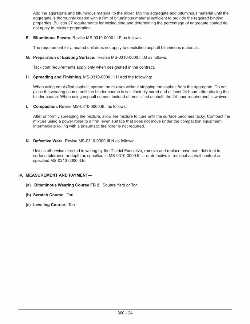
Add the aggregate and bituminous material to the mixer. Mix the aggregate and bituminous material until the aggregate is thoroughly coated with a film of bituminous material sufficient to provide the required binding properties. Bulletin 27 requirements for mixing time and determining the percentage of aggregate coated do not apply to mixture preparation.
E. Bituminous Pavers. Revise MS-0310-0000.III.E as follows:
The requirement for a heated unit does not apply to emulsified asphalt bituminous materials.
G. Preparation of Existing Surface. Revise MS-0310-0000.III.G as follows:
Tack coat requirements apply only when designated in the contract.
H. Spreading and Finishing. MS-0310-0000.III.H Add the following:
When using emulsified asphalt, spread the mixture without stripping the asphalt from the aggregate. Do not place the wearing course until the binder course is satisfactorily cured and at least 24 hours after placing the binder course. When using asphalt cement instead of emulsified asphalt, the 24-hour requirement is waived.
I. Compaction. Revise MS-0310-0000.III.I as follows:
After uniformly spreading the mixture, allow the mixture to cure until the surface becomes tacky. Compact the mixture using a power roller to a firm, even surface that does not move under the compaction equipment. Intermediate rolling with a pneumatic tire roller is not required.
N. Defective Work. Revise MS-0310-0000.III.N as follows:
Unless otherwise directed in writing by the District Executive, remove and replace pavement deficient in surface tolerance or depth as specified in MS-0310-0000.III.L. or defective in residual asphalt content as specified MS-0310-0000.II.E.
IV. MEASUREMENT AND PAYMENT—
(a) Bituminous Wearing Course FB 2. Square Yard or Ton
(b) Scratch Course. Ton
(c) Leveling Course. Ton
300 - 25
MS-0310-0022BITUMINOUS BINDER COURSE FB 2
I. DESCRIPTION—This work is construction of a binder course of plant mixed bituminous concrete on a prepared surface.
II. MATERIAL—MS-0310-0021.II
III. CONSTRUCTION—MS-0310-0021.III, except:
A. Bituminous Mixing Plant.
1. Plant Requirements. In addition, use one bin and two bins.
IV. MEASUREMENT AND PAYMENT—
A Bituminous Binder Course FB 2. Square Yard or Ton
C Leveling Course. Ton

300 - 26
MS-0310-0031BITUMINOUS WEARING COURSE FB 1
I. DESCRIPTION—This work is construction of a wearing course of plant mixed bituminous concrete on a prepared surface.
II. MATERIAL—MS-0310-0021.II, and as follows:
A. Bituminous Material. MS-0310-0021.II.A, except exclude PG 64-22 and PG 58-28 asphalt cement.
B. Aggregate. MS-0310-0021.II.B, except as follows:
1. Fine Aggregate— Publication 408, Section 703.1, Type B, for surface finish only.
2. Coarse Aggregate, Type A— Publication 408 Section 703.2 except the maximum percent passing the 75 µm (No. 200) sieve equals 2 percent.
C. Mixture Composition. MS-0310-0021.II.C, except determine the optimum emulsion content using PTM No. 750.
III. CONSTRUCTION—MS-0310-0021.III, except as follows:
A. Bituminous Mixing Plant.
1. Plant Requirements. Plants do not require equipment for developing the design and control tests according to the Department's Modified Marshall Method.
Use a synchronized, volume proportioning, mobile plant; a stabilization plant; or a stationary plant conforming to the following requirements:
• Mobile plant—Equipped to mix, spread, and strike off surface.
• All plants—Aggregate bins and bituminous tank of sufficient capacity to provide a constant supply and proper proportioning of materials. Provide heating facilities when required to heat aggregate or bituminous materials.
• All plants—Capable of mixing materials to obtain a uniform coating of particles and a thorough distribution of bituminous material throughout the aggregate.
• All plants—Positive driven feed to proportion coarse aggregate from bins and a positive pump to proportion bituminous material coming from the tank.
• All plants—Feeder and pump, synchronized to discharge coarse aggregate and bituminous material in desired proportions for mixing that are calibrated immediately before mixture production.
2. Preparation of Mixture.
a. Aggregates. Dry the aggregate as necessary at a temperature not to exceed 150F, except when using PG 46-40 or PG 52-28 asphalt cements. The Contractor may use damp aggregates with emulsified asphalt.
b. Bituminous Material. Heat the bituminous material to the temperature specified in Section 430.2.
c. Mixing. Add the required quantities of aggregate and bituminous material to the mixer. Mix the aggregate and bituminous material until uniformly coating the aggregate with a film of adequate thickness to provide the required binding properties. Bulletin 27 requirements for mixing and determining the percentage of the aggregate coated do not apply to the mixture.
300 - 27
B. Hauling Equipment. These requirements do not apply when using a mobile plant.
C. Bituminous Pavers. These requirements do not apply when using a mobile plant. The requirement for a heated unit does not apply if the bituminous material is an emulsified asphalt.
D. Preparation of Existing Surface. Tack coat requirements apply only when designated in the contract.
E. Spreading and Finishing. When spreading courses using emulsified asphalt, do not strip asphalt from the aggregate. Unless the mixture contains PG 46-40 or PG 52-28, do not place the wearing course until the binder course is satisfactorily cured and at least 24 hours after placing the binder course. To spread the mixture to the loose depth required to obtain the required compacted depth, the Contractor may use the mobile plant that produced the mixture. After uniformly spreading the mixture, allow the mixture to cure as specified in MS-0310-0021.III.L or until the surface becomes tacky. Using a power roller, compact the mixture to a firm, even surface that does not move under the compaction equipment. Intermediate rolling with a pneumatic tire roller is not required.
F. Mat Density Acceptance. The Representative will accept density when the mixture does not move under compaction equipment.
K. Surface Tolerance. After complying with the surface tolerance requirements specified in MS-0310-000.III.K, while the surface is still tacky, and before opening to traffic, uniformly spread a layer of fine aggregate on the surface at a rate of 3 pounds per square yard to 5 pounds per square yard. Sweep and roll the surface before opening to traffic.
N. Defective Work. Unless otherwise directed in writing by the District Executive, remove and replace pavement deficient in surface tolerance or depth as specified in MS-0310-0000.III.L or defective in residual asphalt content as specified in MS-0310-0000.II.E.
IV. MEASUREMENT AND PAYMENT—
A. Bituminous Wearing Course FB 1.
1. Area Basis. Square Yard
2. Mass (Weight) Basis. Ton
3. Material Used Basis.
a Aggregate. Square Yard or Ton
b Bituminous Material. Gallon
B. Scratch Course.
1. Mass (Weight) Basis. Ton
2. Material Used Basis.
a Aggregate. Ton
b Bituminous Material. Gallon
C. Leveling Course. PUB 408, Section 439.4(b)
300 - 28
0310-0032BITUMINOUS BINDER COURSE FB 1
I. DESCRIPTION—This work is construction of a binder course of plant-mixed bituminous concrete on a prepared surface.
II. MATERIAL—MS-0310-0031.II
III. CONSTRUCTION—MS-0310-0031.III except conform to the surface tolerances specified in MS-0310-0000.III.K.
IV. MEASUREMENT AND PAYMENT—
A. Bituminous Binder Course FB 1.
1. Area Basis. Square Yard
2. Mass (Weight) Basis. Ton
3. Material Used Basis.
(a) Aggregate. Square Yard or Ton
(b) Bituminous Material. Gallon
B. Scratch Course.
1. Mass (Weight) Basis. Ton
2. Material Used Basis.
(a) Aggregate. Ton
(b) Bituminous Material. Gallon
C. Leveling Course. MS-0310-0032.IV.B. Scratch Course.

300 - 29
MS-0310-0051HMA BITUMINOUS WEARING COURSE FJ 1AND BITUMINOUS WEARING COURSE FJ 1C
I. DESCRIPTION—This work is construction of a wearing course of plant mixed bituminous concrete on a prepared surface.
II. MATERIAL— Section 0310-0000.II and as follows:
A. Bituminous Material. Add the following:
• Asphalt Cement, Class PG 64-22.
• The Contractor may use Asphalt Cement, Class PG 58-28 instead of PG 64-22 in Districts 1-0, 2-0, 3-0, 4-0, 9-0, 10-0, 11-0, 12-0, and 5-0 (Monroe, Carbon, and Schuylkill counties only).
E. Mixture Composition. Section 0310-0000.II.E, except add the following JMF and production limits:
• JMF and production stability of at least 1,000 pounds at 140F.
• JMF voids from 3% to 6%. Production limit for voids of ±2 percentage points of the JMF voids and within the master range of 2.0% to 7.0%.
G. Mat Density Acceptance.
The Representative will accept density when the mixture does not move under the compaction equipment.
III. CONSTRUCTION— Section 0310-0000.III, except as follows:
B. Weather Limitations. Revise as follows:
Do not place wearing course from September 15 to May 15 in Districts 1-0, 2-0 (except Juniata and Mifflin counties), 3-0, 4-0, 5-0 (Monroe and Carbon counties only), and 10-0; and from October 1 to May 1 in Districts 2-0 (Juniata and Mifflin counties only), 5-0 (except Monroe and Carbon counties), 6-0, 8-0, 9-0, 11-0, and 12-0. Exceptions to paving weather limitations require the written approval of the District Executive.
C. Bituminous Mixing Plant. Add the following:
1. Plant Requirements. The Contractor may produce the mixture using one bin. If the Contractor chooses to use more than one bin, combine the aggregate according to the JMF.
IV. MEASUREMENT AND PAYMENT—
A. Bituminous Wearing Course FJ 1 or Bituminous Wearing Course FJ 1C. Square Yard or Ton
B. Scratch or Leveling Courses. Ton

300 - 30
MS-0311-0001Bituminous Binder Course CP-2
I. DESCRIPTION -This work is the construction of a penetrated bituminous binder course on a prepared surface.
II. MATERIAL -
A. Bituminous Material. Publication 408, Section 470.2(a)
B. Coarse Aggregate. Type A, No.8 and No. 57, Publication 408, Section 703.2.
C. Bituminous Prime Coat. Publication 408, Section 461.2.
Ill. CONSTRUCTION -
A. Conditioning Existing Surface. Prior to placing binder course, inspect the existing surface for imperfections or defective areas and correct if necessary. Clean the base or existing surface of foreign materials. Before placing, treat with prime coat, as specified in Publication 408, Section 461.3.
B. Spreading No. 57 Aggregate. Spread the No. 57 coarse aggregate with acceptable spreaders. Removesegregated material and replace with suitable graded material. Spread the aggregate so the binder course will be 2 1/2 inches in depth after final compaction.
C. Compaction No. 57 Aggregate. To compact and bond coarse aggregate, dry-roll it using a 10-ton power roller, as specified in Publication 408, Section 1 08.05(c).
Start rolling at sides, overlapping shoulders, and progress to center. On superelevated curves, start rolling on the low side and progress to the high side. Roll parallel to the centerline of roadway, lapping each preceding track and covering the entire surface with the rear wheels, until the surface is firm, even, and uniform. Continue rolling, as directed, until the material does not creep or wave ahead of roller wheels.
Along curbs, walls, and at other areas not accessible to the roller, the material should be tamped thoroughly with mechanical or hand tampers. The tampers used should have a minimum weight-to-area ratio of 0.5 pounds per square inch.
D. Test No. 57 Aggregate Thickness and Surface Tolerance. Once the No. 57 aggregate has been spread and rolled, test the depth before applying bituminous materials. The test is executed by digging three holes at approximately 200-foot intervals (one test hole at the center and one at each quarter point). Correct deviations in excess of 1/2 inch by loosening the surface, removing or adding No.5 aggregate, and rerollingthe surface.
Before the bituminous application, test the binder course surface, as specified in Publication 408, Section409.3(1). Correct irregularities of more than 1/2 inch.
E. Application of Bituminous Material. Use a bituminous distributor as specified in Publication 408, Section460.3(b).
Apply bituminous material when the entire surface is in condition to permit satisfactory penetration and adhesion, when the aggregate is dry, and when the ambient temperature is between the bituminous material application temperature ranges specified in Publication 408, Section 470.2(a) or, if using CRS-1 PM, from 35 to 55°F. Do not apply emulsified asphalt if, in the Qualified Inspector's opinion, rain is imminent or if the Inspector expects freezing temperatures within 24 hours after the application. Do not apply RS-2(E-2), CRS-2(E-3), RS-2PM (E-2M), CRS-2PM (E-3M), or PG 46-40 from September 15 to May 1 in Districts 1-0, 2-0,3-0,4-0, 9-0, 10-0, 11-0, 12-0, and 5-0 (Monroe, Carbon, and Schuylkill Counties only); and from October 1 to May 1 in Districts 6-0, 8-0, and 5-0 (Berks, Lehigh, and Northampton Counties only).
Apply bituminous material to damp aggregates at a rate of 1.20 to 1.80 gallons/square yard. Increase 10% to 15% when slag is used.
300 - 31
Remove and replace aggregate contaminated with dirt or other foreign substances.
Depending upon labor and equipment available for handling the aggregate, gage the length of road surface to be penetrated to obtain proper spreading and compaction. Insure uniformity at the junction of two (2) applications.
In areas inaccessible to the distributor, spread bituminous material with portable pressure units.
F. Spreading No.8 Aggregate. Immediately after applying the first layer of bituminous material, spread No. 8aggregate with acceptable spreaders at a rate of 15 to 20 pounds/square yard. Decrease by 13% when slag is used. Spread ahead of the wheels on the spreader so that the bituminous material is covered before the wheels pass over it.
G. Compaction of No. 8 Aggregate. After the No. 8 aggregate is spread, start rolling the surface while the bitumen is warm. Broom additional No. 8 aggregate into voids during the rolling process until the entire surface voids are uniformly filled, leaving the No. 57 aggregate completely covered. The equipment and rolling pattern are specified in Subsection III.C.
H. Mat Density Acceptance. The Representative will accept density when the mixture does not move undercompaction equipment.
I. Tests for Depth of Binder Course. After application of No. 8 choke aggregate and after final compaction, test the depth of binder course and correct, if necessary, as specified in Publication 408, Section 409.3(m).
J. Protection of Binder Course. Do not allow vehicular traffic or loads on completed binder course until adequate stability has been attained and the material is sufficiently cured to prevent distortion, flushing of bituminous material to surface, or loss of aggregate. Before placing the next application, the binder course must be satisfactorily cured. Maintain and Protect binder course, as provided in Publication 408, Section 901.
IV. MEASUREMENT AND PAYMENT.
A. Bituminous Binder Course CP-2. Square Yard.
B. Bituminous Prime Coat. Publication 408, Section 461.4.
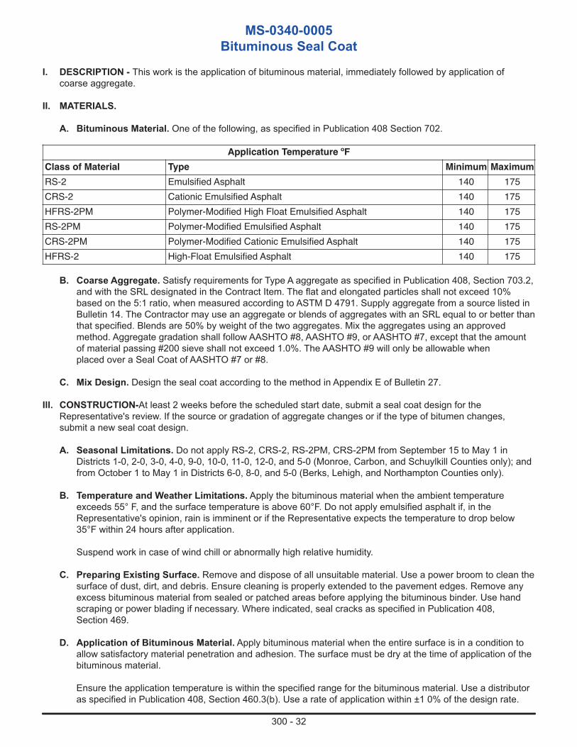
300 - 32
MS-0340-0005Bituminous Seal Coat
I. DESCRIPTION - This work is the application of bituminous material, immediately followed by application of coarse aggregate.
II. MATERIALS.
A. Bituminous Material. One of the following, as specified in Publication 408 Section 702.
Application Temperature ºFClass of Material Type Minimum MaximumRS-2 Emulsified Asphalt 140 175CRS-2 Cationic Emulsified Asphalt 140 175HFRS-2PM Polymer-Modified High Float Emulsified Asphalt 140 175RS-2PM Polymer-Modified Emulsified Asphalt 140 175CRS-2PM Polymer-Modified Cationic Emulsified Asphalt 140 175HFRS-2 High-Float Emulsified Asphalt 140 175
B. Coarse Aggregate. Satisfy requirements for Type A aggregate as specified in Publication 408, Section 703.2, and with the SRL designated in the Contract Item. The flat and elongated particles shall not exceed 10% based on the 5:1 ratio, when measured according to ASTM D 4791. Supply aggregate from a source listed in Bulletin 14. The Contractor may use an aggregate or blends of aggregates with an SRL equal to or better than that specified. Blends are 50% by weight of the two aggregates. Mix the aggregates using an approved method. Aggregate gradation shall follow AASHTO #8, AASHTO #9, or AASHTO #7, except that the amount of material passing #200 sieve shall not exceed 1.0%. The AASHTO #9 will only be allowable when placed over a Seal Coat of AASHTO #7 or #8.
C. Mix Design. Design the seal coat according to the method in Appendix E of Bulletin 27.
Ill. CONSTRUCTION-At least 2 weeks before the scheduled start date, submit a seal coat design for the Representative's review. If the source or gradation of aggregate changes or if the type of bitumen changes, submit a new seal coat design.
A. Seasonal Limitations. Do not apply RS-2, CRS-2, RS-2PM, CRS-2PM from September 15 to May 1 in Districts 1-0, 2-0, 3-0, 4-0, 9-0, 10-0, 11-0, 12-0, and 5-0 (Monroe, Carbon, and Schuylkill Counties only); and from October 1 to May 1 in Districts 6-0, 8-0, and 5-0 (Berks, Lehigh, and Northampton Counties only).
B. Temperature and Weather Limitations. Apply the bituminous material when the ambient temperature exceeds 55° F, and the surface temperature is above 60°F. Do not apply emulsified asphalt if, in the Representative's opinion, rain is imminent or if the Representative expects the temperature to drop below 35°F within 24 hours after application.
Suspend work in case of wind chill or abnormally high relative humidity.
C. Preparing Existing Surface. Remove and dispose of all unsuitable material. Use a power broom to clean the surface of dust, dirt, and debris. Ensure cleaning is properly extended to the pavement edges. Remove any excess bituminous material from sealed or patched areas before applying the bituminous binder. Use hand scraping or power blading if necessary. Where indicated, seal cracks as specified in Publication 408, Section 469.
D. Application of Bituminous Material. Apply bituminous material when the entire surface is in a condition to allow satisfactory material penetration and adhesion. The surface must be dry at the time of application of the bituminous material.
Ensure the application temperature is within the specified range for the bituminous material. Use a distributor as specified in Publication 408, Section 460.3(b). Use a rate of application within ±1 0% of the design rate.
300 - 33
Determine the distributor application rate in the field according to PTM No. 747. Application of the bituminous material must be consistent and uniform in both transverse and longitudinal directions. In case of erratic and non-uniform application, suspend the operation until the problem is properly addressed.
For inaccessible areas, uniformly spread the bituminous material over the surface using portable pressure units. The quantity of material placed at one time shall be consistent with the facilities for handling, spreading, and rolling coarse aggregate, as well as the temperature of the surface and bituminous material.
Uniformly spread the bituminous material at the junction of separate applications.
E. Spreading and Rolling Coarse Aggregate. Use dry aggregates, except the Contractor may use damp aggregates with emulsified asphalt. Before spreading aggregate, calibrate the spreader using a method acceptable to the Inspector-in-Charge. Immediately after applying the bituminous material, uniformly spread a single layer of coarse aggregate at the design rate using a mechanical spreader capable of spreading 15 pounds per square yard to 25 pounds per square yard. The application rate of chips will provide a complete coverage of the surface, with no deficient areas. No asphalt shall cover the aggregate. The spreader shall be self-propelled, equipped with pneumatic tires and equipped with a screen to remove oversized material. The spreader shall follow the bitumen distributor within 100 feet.
Roll the aggregate with pneumatic-tire rollers, as specified in Publication 408, Section 108.05(c)3.f. Provide a sufficient number of rollers to roll the width of stone spread with one pass. Use a contact pressure from 40 pounds per square inch to 50 pounds per square inch. Rollers shall follow the aggregate spreader closely and embed the aggregate into the emulsion before breaking. The roller's speed shall be slow enough to prevent pushing the chips.
F. Protection of Surface. Do not allow vehicular traffic or loads on the newly completed surface until the material obtains adequate stability and adhesion and the material is sufficiently cured to prevent distortion, flushing of bituminous material to the surface, and loss of aggregate.
Provide sufficient flaggers and pilot vehicles to move traffic through the work zone or over the completed work at speeds that prevent aggregate distortion or pick-up. If required, sweep the surface with a power broom to remove loose aggregate before and after opening the road to traffic. Provide a pilot car for sweeping operations after opening the road to traffic.
IV. MEASUREMENT AND PAYMENT -
A. Area Basis. Square Yard
B. Material Used Basis.
1. Coarse Aggregate. Square Yard
2. Bituminous Material. Gallon
C. Crack Filling and Sealing. Publication 408, Section 469.4
300 - 34
MS-0350-0018Bituminous Fiber Reinforced Seal Coat
I. DESCRIPTION- This work is application of bituminous fiber-reinforced material immediately followed by application of coarse aggregate.
II. MATERIAL-
A. Bituminous Seal Coat Material. Polymer-modified Asphalt Emulsion. Publication 408 Section 702(a).
B. Coarse Aggregate. Satisfy requirements for Type A aggregates as specified in Publication 408, Section 703.2(a), with the SRL designated in the Contract Item. The flat and elongated particles shall not exceed 1 0% based on the 5:1 ratio, when measured according to ASTM D 4791. Supply aggregate from a source listed in Bulletin 14. The Contractor may use an aggregate or blends of aggregate with an SRL equal to or better than that specified. Blends are 50% by weight of each aggregate. Mix the aggregate by an approved method. Aggregate gradation shall follow AASHTO #8 or AASHTO #7, except that the amount of material passing #200 sieve shall not exceed 1 percent.
C. Fiber. Type E-Glass Fiber (ASTM D578-05 (2011), paragraph 4.2.2).
1. Certify using Municipal Services form MS-447A.
D. Mix Design. Design the seal coat according to the method in Appendix E of Bulletin 27 (Pennsylvania Design Method for Seal Coats and Surface Treatments).
Ill. CONSTRUCTION-At least 2 weeks before the scheduled start date, submit a seal coat design for the Representative's review. If the source or gradation of aggregate changes or type of polymer-modified asphalt emulsion changes, submit a new design.
A. Seasonal Limitations. Fiber-reinforced seal coat shall be placed between May 1 and September 15 in Districts 1-0, 2-0, 3-0, 4-0, 9-0, 10-0, 11-0, 12-0, and 5-0 (Monroe, Carbon, and Schuylkill Counties only); and between May 1 and October 1 in Districts 6-0, 8-0, and 5-0 (Berks, Lehigh, and Northampton Counties only).
B. Temperature and Weather Limitations. Apply the polymer-modified emulsion when the ambient temperature exceeds 55°F and the surface temperature is above 60°F, unless allowed in writing by the Representative. Do not apply polymer-modified asphalt emulsion if, in the Representative's opinion, rain is imminent or if the Representative expects the temperature to drop below 35°F within 24 hours after application. Suspend work in case of wind chill or abnormally high relative humidity.
C. Preparing Existing Surface. Remove and dispose of all unsuitable material. Use a power broom to clean the surface from dust, dirt, and debris. Ensure that cleaning is properly extended to the pavement edges. Remove any excess bituminous material from sealed or patched areas before applying the bituminous binder. Use hand scraping or power blading if necessary. Where indicated, seal cracks as specified in Publication 408, Section 469.3(d).
D. Application of Bituminous Material. Publication 408, Section 470.3(b). Using a specifically designed trailer system, apply bituminous material at a rate of 0.2 gallon per square yard to 0.80 gallon per square yard and the fiber at a rate of 0.055 pounds per square yard to 0.166 pounds per square yard, in accordance with the specific project's requirements. Apply when the entire surface is in a condition to allow satisfactory material penetration and adhesion. Gage quantity of material placed at one time to maintain the requirements for handling, spreading, and rolling coarse aggregate, as well as the temperature of the surface and bituminous material. Ensure uniformity at the junction of two applications. Ensure that the application temperature is within the specified range for the bituminous material. Application of the bituminous material must be consistent and uniform in both transverse and longitudinal directions. In case of erratic and nonuniform application, suspend the operation until the problem is properly addressed.
E. Spreading and Rolling Coarse Aggregate. Before spreading aggregate, calibrate the spreader using a method acceptable to the Inspector-in-charge. Immediately after applying the bituminous material and the fiber, uniformly spread a single layer of coarse aggregate at the design rate using a mechanical spreader
300 - 35
capable of spreading 15 pounds per square yard to 25 pounds per square yard. The application rate of chips shall provide a complete coverage of the surface, with no deficient areas. No asphalt shall cover the aggregate. The spreader shall be self-propelled, equipped with pneumatic tires and equipped with a screen to remove oversized material. The spreader shall follow the bitumen distributor within 100 feet.
Roll the aggregate with pneumatic-tire rollers, as specified in Section 1 08.05(c) 3.f. Use a contact pressure from 40 pounds per square inch to 50 pounds per square inch. This surface treatment requires at least two roller passes. Rollers shall follow the aggregate spreader closely and embed the aggregate into the emulsion before breaking. The roller's speed shall be slow enough to prevent pushing the chips.
F. Protection of Surface. Publication 408, Section 470.3(d). Do not allow vehicular traffic or loads on the newly completed surface until the material obtains adequate stability and adhesion and the material is sufficiently cured to prevent distortion, flushing of bituminous material to the surface, and loss of aggregate. Maintain the Work Zone in compliance with Pub. 213.
G. Special Considerations. As per the pre-construction survey, the rate of asphalt and fiber application may need to be adjusted to address the conditions of the surface to be treated. Surfaces that have significant cracks wider than 1/8 inch and/or are severely cracked require a 10% or more increase in the rate of emulsion application. All cracks wider than 1/8 inch need to be sealed in accordance with Publication 408, Section 469.3(d).
IV. MEASUREMENT AND PAYMENT-
A. Area Basis. Square Yard.
B. Material Used Basis.
1. Coarse Aggregate. Square Yard.
2. Bituminous Fiber-Reinforced Material. Square Yard.
3. Bituminous Material. Gallon.
C. Asphalt Joint and Crack Sealing. Linear Foot. For the type specified.
300 - 36
MS-0360-0019Bituminous Fiber Reinforced Stress Absorbing Membrane Interlayer
I. DESCRIPTION — This work involves an application of bituminous fiber reinforced Stress Absorbing Membrane Interlayer (SAMI) material immediately followed by an application of cover aggregate. Cover aggregate is followed by construction of an approved asphalt-based surface overlay.
II. MATERIAL —
A. SAMI.
1. Bituminous Seal Coat Material. Polymer-modified Emulsified Asphalt. Publication 408, Section 470.2(a).
2. Coarse Aggregate. Type A, No. 8—Publication 408, Section 703.2. Revise the following requirements of Table D:
• All other uses % Maximum is 1.0.
From a Bulletin 14 approved source. Use coarse aggregate with the SRL designation, or better, indicated in the bid proposal.
3. Fiber. Type E-Glass Fiber. (ASTM D578-05, paragraph 4.2.2).
a. Certify using Municipal Services form MS-447A.
B. Bituminous Overlay.
1. Superpave Mixture Design, Standard and RPS Construction of Plant-Mixed HMA Courses.Publication 408, Section 409.2 and Section 411.2.
2. Bituminous Wearing Course FJ-1 and Bituminous Wearing Course FJ-1C.Publication 408, Section 422.2 and Section 411.2.
3. Bituminous Wearing Course FB-2. Publication 447 MS-0310-0021.
4. Bituminous Wearing Course FB-1. Publication 447 MS-0310-0031.
5. Polymer-Modified Emulsified Asphalt Paving System. Publication 408 Section 483.2.
6. Ultra-Thin Friction Course. Publication 408 Section 489.2.
7. Slurry Seal. Publication 408, Section 482.2.
8. FB-3 Wearing. Publication 447 MS-0310-0011
III. CONSTRUCTION — At least 2 weeks before beginning work, submit a SAMI design to the Representative for review. Use the design method in Appendix E of Bulletin 27 (Pennsylvania Design Method for Seal Coats and Surface Treatments) as a guideline. If source or gradation of aggregate or type of polymer modified asphalt emulsion is changed submit a new design.
A. SAMI.
1. Preparing Existing Surface. Remove and dispose of all unsuitable material. Where indicated, seal cracks as specified in Publication 408, Section 469.3(d).
2. Application of Bituminous Fiber Reinforced Material. Use a trailer system that applies glass fiber between two layers of polymer modified emulsified asphalt. Apply the SAMI when the entire surface is in a condition to allow satisfactory material penetration and adhesion, and when the air, surface, and
300 - 37
aggregate temperatures are 16ºC (60ºF) or higher unless allowed in writing by the Representative. Do not apply polymer modified emulsified asphalt if, in the Representative’s opinion, rain is imminent or if freezing temperatures are expected within 24 hours after application. Do not apply RS-2(E-2), CRS-2(E-3), RS2-PM(E-2M), CRS-2PM(E-3M), or PG 46-40 from September 15 to May 1 in Districts 1-0, 2-0, 3-0, 4-0, 9-0, 10-0, 11-0, 12-0, and 5-0 (Monroe, Carbon, and Schuylkill Counties only); and from October1 to May 1 in Districts 6-0, 8-0, and 5-0 (Berks, Lehigh, and Northampton Counties only). Apply the SAMI material at a rate of 0.20 gallon per square yard to 0.50 gallon per square yard total for both applications. Determine the distributor application rate in the field in accordance with PTM No. 747. Apply the fiber at a rate of 0.11 lbs per square yard to 0.221 lbs per square yard, in accordance with the specific projects requirements.
Gage quantity of material placed at one time to maintain the requirements for handling, spreading, and rolling coarse aggregate, as well as the temperature of the surface and the bituminous material. Insure uniformity at the junction of two applications.
3. Spreading and Rolling Coarse Aggregate. Before spreading cover aggregate, calibrate the spreader using a method acceptable to the Inspector-in-Charge.
Determine the proper rate of application of coarse aggregate, in accordance with the design, and immediately following the application of bituminous material, use a mechanical spreader to uniformly spread 10 pounds per square yard to 25 pounds per square yard of binding coarse aggregate, in a single layer. Do not use wet aggregates although damp aggregates may be used.
Use sufficient number of pneumatic-tire rollers, as specified in Publication 408, Section 108.05(c) 3.f., with contact pressure of 40 to 50 psi to cover the width of stone spread during the first pass.
4. Protection of Surface. Publication 408, Section 470.3(d). Do not allow vehicular traffic or loads on the newly completed surface until the material obtains adequate stability and adhesion and the material is sufficiently cured to prevent distortion, flushing of bituminous material to surface, and/or loss of aggregate. Work Zone must comply with Pub. 213 and the MUTCD.
IV. MEASUREMENT and PAYMENT —
A. SAMI
1. Area Basis. Square Yard
2. Material Used Basis.
a. Coarse Aggregate. Square Yard or Ton
b. Bituminous Fiber Reinforced Stress Absorbing Membrane Interlayer Material.Sq. Yard
c. Asphalt Joint and Crack Sealing. Linear Foot for the type specified.
B. Bituminous Overlay
1. Superpave Mixture Design, Standard and RPS Construction of Plant-Mixed HMA Courses.
2. Bituminous Wearing Course FB-2. Square Yard or Ton.
3. Bituminous Wearing Course FB-1.
a. Area Basis. Square Yard.
b. Mass (Weight) Basis. Ton.
c. Material Used Basis.
300 - 38
c1.Aggregate. Square Yard or Ton.
c2.Bituminous Material. Gallon.
4. Polymer-Modified Emulsified Asphalt Paving System.
a. Micro-Surfacing.
a1. Area Basis. Square Yard
a2. Mass (Weight Basis). Ton
b. Bituminous Tack Coat. Gallon
c. Asphalt Joint Crack Sealing. Linear Foot
5. Seal. Square Yard
6. FB-3 Wearing. Wearing Square yard or Ton
300 - 39
MS-0370-0005Pulverization
I. DESCRIPTION — This work consists of the in-place pulverization and uniform blending of existing roadway surface materials and a predetermined thickness of underlying material creating a homogenous mixture of reclaimed base material. The work also consists of shaping, finishing, fine grading, and compaction of the reclaimed base material.
II. MATERIAL —
A. Reclaimed Material. 95% of the pulverized surface material is required to pass through a 2 inch sieve. Incorporate all reclaimed material into the base.
1. Reclaimed Aggregate Material (RAM). In-situ aggregate material which is incorporated in the base.
2. Reclaimed Asphalt Pavement (RAP). Processed paving material containing asphalt cement and aggregates.
B. Composition of Mixture. Remove samples of RAP and RAM to the specified depth and perform the appropriate testing to determine the appropriate or Optimum Moisture Content (OMC) and corresponding Maximum Dry Density (MDD) use ASTM D698.
III. CONSTRUCTION —
A. Equipment.
1. Maintain all equipment in a satisfactory operating condition as specified in Publication 408, Section 108.05(c).
2. Reclaimer. Use a self-propelled rotary reclaimer or equivalent machine capable of cutting through existing roadway materials to depths of up to 16 inches with one pass. Provide equipment capable of pulverizing the existing pavement, base, and subgrade at a minimum width of 8 feet. The cutting drum must have the ability to operate at various speeds (rpm), independent of the machine’s forward speed, in order to control oversized material and gradation.
Use a machine equipped with a computerized integral liquid proportioning system capable of regulating and monitoring the water application rate relative to depth of cut, width of cut, and speed. Have the water pump on the machine connected by a hose to the supply tanker/distributor, and mechanically or electronically interlocked with the forward movement/ground speed of the machine. Mount the spray bar to allow the water to be injected directly into the cutting drum/mixing chamber.
3. Placement Equipment. Motor Grader or by another method approved by the Inspector.
4. Compaction Equipment. Vibratory pad-foot roller 52,000- pounds centrifugal force or Pneumatic Tire Roller 25 Ton for breakdown compaction. Single or Tandem steel drum (static) roller 12-14 Ton for finish rolling.
B. Weather Limitations. Do not place paving mixtures from November 1 to March 31 unless allowed in writing by the District Executive. Do not place mixtures when surfaces are wet or when the air or surface temperatureis 40°F or lower.
C. General. Pulverization consists of a series of steps that include pulverizing and mixing of the existing roadway surface between 5-16 inches in depth with the aggregate base. The Motor grader is used to move and place the reclaimed material to the desired longitudinal grade and cross-slope.
D. Compaction. Shape, grade, and compact to the lines, grades, and depth shown on the plans and cross sections. Commence rolling at the low side of the course. Leave 3 to 6 inches from any unsupported edge(s) unrolled initially to prevent distortion. When material is too coarse more than 20% retained on the 3/4 inch sieve and less than 35% passing the Number 200 sieve, or more than 30% retained on the 3/4 inch sieve to

300 - 40
use these methods, compaction will be determined on non-movement of material under compaction equipment specified in Publication 408, Section 210.3(a). Compact until pulverized material does not rut under a loaded tri-axle.
E. Finishing. Complete all portions of the pulverization during daylight hours, unless otherwise allowed.
F. Protection. Protect any finished portion of the pulverized material upon which any construction equipment is required to travel to prevent marring, distortion or damage of any kind. Immediately and satisfactorily correct any such damage.
G. Surface Tolerance. When directed by the Inspector, test the completed base course for smoothness and accuracy of grade, both transversely and longitudinally using suitable templates and straightedges. Satisfactorily correct any 3000 square yard area where the average surface irregularity exceeds 1/2 inch under a template or straightedge, based on a minimum of at least three measurements.
IV. MEASUREMENT and PAYMENT —
A. Pulverized Base. Square Yard.
300 - 41
Use and Design Guidelines for Evaluating and Determining the appropriate Full Depth Reclamation (FDR) Stabilization Method
contained in Publication 447 for use by Municipalities
OBJECTIVE
The purpose of this document is to provide municipalities with a process for determining which FDR Stabilizationmethod is the best for a particular roadway location. The recommended procedure consists of three basic steps whichare listed below in the “Process Description” and further discussed in the remainder of the document.
Following this procedure will provide greater assurance of selecting the proper stabilization method and achieving the desired performance of the finished roadway.
INTRODUCTION
“Full Depth Reclamation is the pavement rehabilitation technique in which the full thickness of the asphalt pavementand a predetermined portion of the underlying materials (base, subbase and/or subgrade) is uniformly pulverized andblended to provide an upgraded homogenous base material. Further stabilization may be obtained through the use of available additives.” (Asphalt Recycling and Reclaiming Association (ARRA)).
Four different types of material stabilization are used:
1) Mechanical – Granular materials such as crushed stone, gravel, and/or Reclaimed Asphalt Pavement (RAP) are added to improve the in-place materials.
2) Calcium Chloride – Liquid Calcium Chloride is used.
3) Chemical – Cement, Lime-Pozzolan, and Lime/Fly Ash (L/FA) are used. Hydrated Lime or Fly Ash will notbe used as a singular additive, but will be used as a combination of the two.
4) Bituminous – Slow or medium set asphalt emulsions are usually used. Small amounts of hydrated lime or cement, typically 1.5 and 1.0 percent respectively by weight, are being added with asphalt emulsion to produce reclaimed mixtures with higher early strength and greater resistance to water damage.
PROCESS DESCRIPTION
A thorough project evaluation, by the owner, is essential to promote success. Prior to starting the evaluation contactyour District Municipal Services Representative.
The project evaluation consists of the following: 1. Roadway Condition Survey2. Traffic Level and Type3. Sampling and Testing for Recommended Stabilization Method
1) Roadway Condition SurveyAn on-site evaluation of the roadway should be done and take into account the following conditions:
• Grade and Slope of existing roadway• Evidence of water damage and the underlying cause• Drainage along shoulders• Condition of Shoulders if there are shoulders present• Existing Driving Surface
Other conditions may be observed and should be noted to aid in the final process decision.
2) Traffic Level and TypeAverage Daily Traffic (ADT) should suffice on low volume roads. The exception is when heavy vehicle loading is present such as large farm vehicles, quarry traffic, waste material haulers or incidental traffic due to specialized projects (Drilling, etc.).
300 - 42
3) Sampling and Testing for Recommended Stabilization MethodA minimum of three sample locations are required per road with additional locations selected upon pavementsconditions and variability. Sample locations are to be selected following Pennsylvania Test Method (PTM #1). PTM #1 can be found at the following location.www.dot.state.pa.us/public/.../PUBLICATIONS/PUB_19/PTM_TOC.pdf
The minimum is 1 (one) sample every 500 linear feet but cannot be less than 3 (three) samples per road. Samples for each roadway are necessary to account for changes in soil conditions that typically occur between different locations. Each sample shall contain sufficient material to perform all the required evaluation testing. Sampling can be done by coring or milling. Samples of asphalt materials, granular base and subgrade soils must be obtained for laboratory evaluation.
Laboratory Testing(Qualified1 Lab or Technical Representative to be approved by the Municipality).
1) Select a Qualified Laboratory or Technical Representative to do preliminary testing.
2) Samples shall be taken from the field and Table 2 will be used to determine which testing shall be done.
3) Once the preliminary testing is completed the qualified entity will determine which stabilization method(s) to use based on the Characteristics of the Reclaimed Pavement Materials in Table 3.
4) When the qualified entity has determined the recommended stabilization method to use, further testing is done and certified designs are developed to determine the quantities of the recommended additives as outlined in the specification of the recommended stabilization method.
Tables 2, 3, and 4 are in Appendix ATesting of the RAP, the subgrade soils and a mixture of the two will dictate whether an additive is needed, as well asthe type and amount to be applied. Minimum testing for RAP shall include an extraction for asphalt content and an aggregate sieve analysis. Minimum testing for soils shall include a sieve analysis, sand equivalent, liquid limit, plasticlimit, and plasticity index (PI). General guidelines for selecting stabilizers based on these tests are included in Table 3.Additional strength tests on the stabilized materials can be used in structural design of the pavement.
Laboratory testing may vary considerably because of the wide range of pavement materials and stabilizing agentsthat are involved. The recycled material can consist of nearly 100% RAP or may contain appreciable amounts of thegranular base or soil blended with the RAP. After the stabilization method is determined, further testing is required todetermine the quantity of the stabilizing agents (Table 4).
Table 2 lists several tests that can be performed on the reclaimed mixtures. It is important to note that many tests onthe asphalt mixture are not conducted unless bituminous stabilization is being considered. Once these tests are performed and the composition of the subject pavement is known it is time to select an additive and determine the mix design.
1A Qualified Lab or Technical Representative shall have experience performing the tests required. If there are noQualified Labs or Technical Representatives in the local area the District Materials Engineer/District Materials Manager (DME/DMM) must approve any requested Lab or Technical Representative.
300 - 43
Additive Selection/DesignTo select the type of additive the reclaimed material characteristics are evaluated. Mixture testing is done with the appropriate additives based on the “Characteristics of Reclaimed Pavement Materials” listed in Table 3.
The test procedures in Table 4 are designed to determine the additive amount necessary for achieving adequatestructural strength with the in-place combination of soils and RAP. Material variations, especially in the underlyinggranular soils, usually necessitates structural design based on the worst case scenario to prevent pavement failures.
Additive Selection GuideAsphalt emulsion is easy to apply and dust free. An emulsion stabilized base course is flexible and is not prone tocracking. When in-place moisture levels are high, adding emulsion can increase moisture contents above optimum resulting in an unstable layer.
Cement is easy to apply dry or as a slurry. Cement improves resistance to moisture and develops good earlystrength, but shrinkage cracking can be a problem unless cement content is kept low (usually less than 6%).
Calcium Chloride is a hygroscopic chemical (it absorbs moisture). This moisture facilitates compaction and then imparts strength. Calcium Chloride has been shown to reduce frost heaving.
L/FA (Lime/Fly Ash) increases the amount of silicates in silicate deficient silty materials which allows for properstrength gain to take place.
It is important to note when considering these stabilizers that various combinations of them can be used together for various reasons.

Appendix A
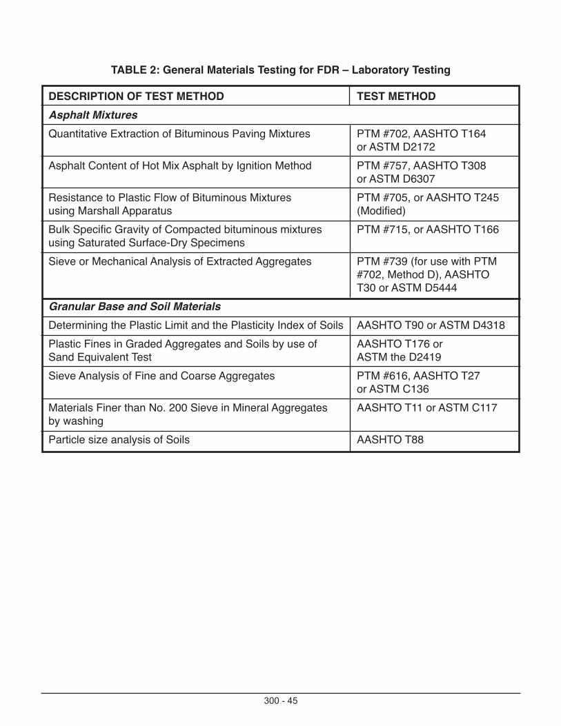
300 - 45
TABLE 2: General Materials Testing for FDR – Laboratory Testing
DESCRIPTION OF TEST METHOD TEST METHODAsphalt MixturesQuantitative Extraction of Bituminous Paving Mixtures PTM #702, AASHTO T164
or ASTM D2172 Asphalt Content of Hot Mix Asphalt by Ignition Method PTM #757, AASHTO T308
or ASTM D6307Resistance to Plastic Flow of Bituminous Mixtures PTM #705, or AASHTO T245using Marshall Apparatus (Modified) Bulk Specific Gravity of Compacted bituminous mixtures PTM #715, or AASHTO T166using Saturated Surface-Dry SpecimensSieve or Mechanical Analysis of Extracted Aggregates PTM #739 (for use with PTM
#702, Method D), AASHTO T30 or ASTM D5444
Granular Base and Soil MaterialsDetermining the Plastic Limit and the Plasticity Index of Soils AASHTO T90 or ASTM D4318Plastic Fines in Graded Aggregates and Soils by use of AASHTO T176 or Sand Equivalent Test ASTM the D2419Sieve Analysis of Fine and Coarse Aggregates PTM #616, AASHTO T27
or ASTM C136Materials Finer than No. 200 Sieve in Mineral Aggregates AASHTO T11 or ASTM C117by washingParticle size analysis of Soils AASHTO T88
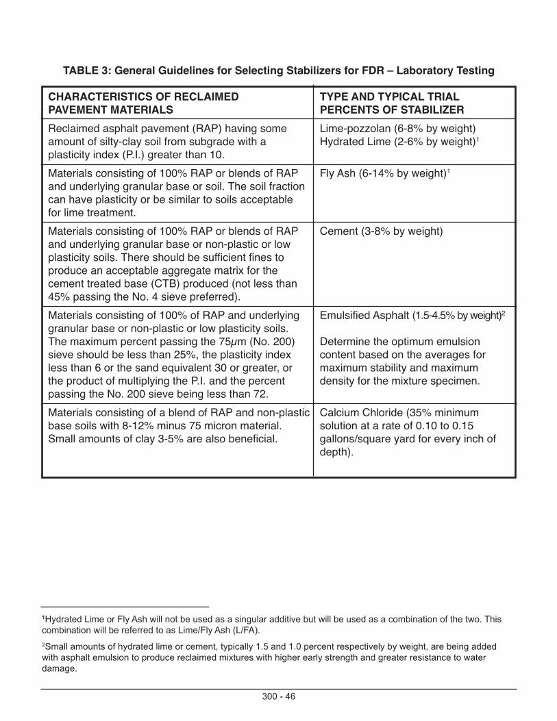
300 - 46
TABLE 3: General Guidelines for Selecting Stabilizers for FDR – Laboratory Testing
CHARACTERISTICS OF RECLAIMED TYPE AND TYPICAL TRIALPAVEMENT MATERIALS PERCENTS OF STABILIZERReclaimed asphalt pavement (RAP) having some Lime-pozzolan (6-8% by weight)amount of silty-clay soil from subgrade with a Hydrated Lime (2-6% by weight)1plasticity index (P.I.) greater than 10.Materials consisting of 100% RAP or blends of RAP Fly Ash (6-14% by weight)1and underlying granular base or soil. The soil fraction can have plasticity or be similar to soils acceptable for lime treatment. Materials consisting of 100% RAP or blends of RAP Cement (3-8% by weight)and underlying granular base or non-plastic or low plasticity soils. There should be sufficient fines to produce an acceptable aggregate matrix for the cement treated base (CTB) produced (not less than 45% passing the No. 4 sieve preferred).Materials consisting of 100% of RAP and underlying Emulsified Asphalt (1.5-4.5% by weight)2granular base or non-plastic or low plasticity soils.The maximum percent passing the 75µm (No. 200) Determine the optimum emulsion sieve should be less than 25%, the plasticity index content based on the averages forless than 6 or the sand equivalent 30 or greater, or maximum stability and maximumthe product of multiplying the P.I. and the percent density for the mixture specimen.passing the No. 200 sieve being less than 72.Materials consisting of a blend of RAP and non-plastic Calcium Chloride (35% minimumbase soils with 8-12% minus 75 micron material. solution at a rate of 0.10 to 0.15Small amounts of clay 3-5% are also beneficial. gallons/square yard for every inch of
depth).
1Hydrated Lime or Fly Ash will not be used as a singular additive but will be used as a combination of the two. Thiscombination will be referred to as Lime/Fly Ash (L/FA).2Small amounts of hydrated lime or cement, typically 1.5 and 1.0 percent respectively by weight, are being addedwith asphalt emulsion to produce reclaimed mixtures with higher early strength and greater resistance to water damage.
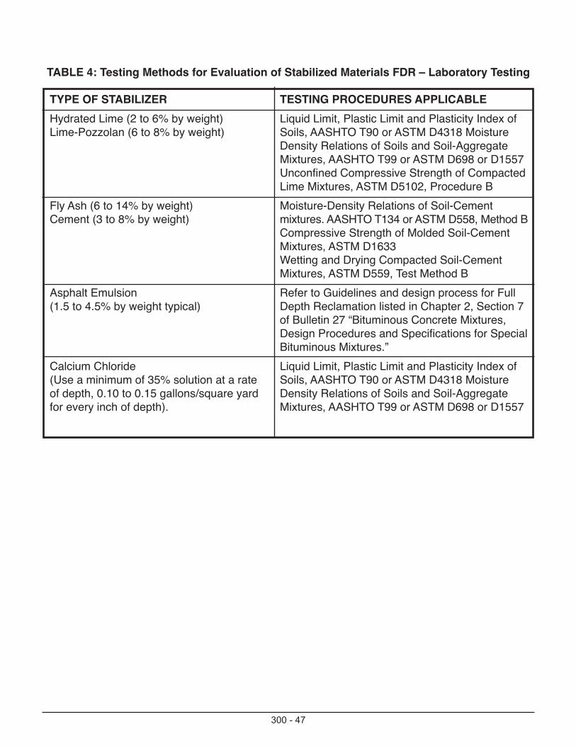
300 - 47
TABLE 4: Testing Methods for Evaluation of Stabilized Materials FDR – Laboratory Testing
TYPE OF STABILIZER TESTING PROCEDURES APPLICABLE Hydrated Lime (2 to 6% by weight) Liquid Limit, Plastic Limit and Plasticity Index ofLime-Pozzolan (6 to 8% by weight) Soils, AASHTO T90 or ASTM D4318 Moisture
Density Relations of Soils and Soil-Aggregate Mixtures, AASHTO T99 or ASTM D698 or D1557Unconfined Compressive Strength of Compacted Lime Mixtures, ASTM D5102, Procedure B
Fly Ash (6 to 14% by weight) Moisture-Density Relations of Soil-Cement Cement (3 to 8% by weight) mixtures. AASHTO T134 or ASTM D558, Method B
Compressive Strength of Molded Soil-Cement Mixtures, ASTM D1633Wetting and Drying Compacted Soil-Cement Mixtures, ASTM D559, Test Method B
Asphalt Emulsion Refer to Guidelines and design process for Full(1.5 to 4.5% by weight typical) Depth Reclamation listed in Chapter 2, Section 7
of Bulletin 27 “Bituminous Concrete Mixtures, Design Procedures and Specifications for SpecialBituminous Mixtures.”
Calcium Chloride Liquid Limit, Plastic Limit and Plasticity Index of(Use a minimum of 35% solution at a rate Soils, AASHTO T90 or ASTM D4318 Moisture of depth, 0.10 to 0.15 gallons/square yard Density Relations of Soils and Soil-Aggregate for every inch of depth). Mixtures, AASHTO T99 or ASTM D698 or D1557
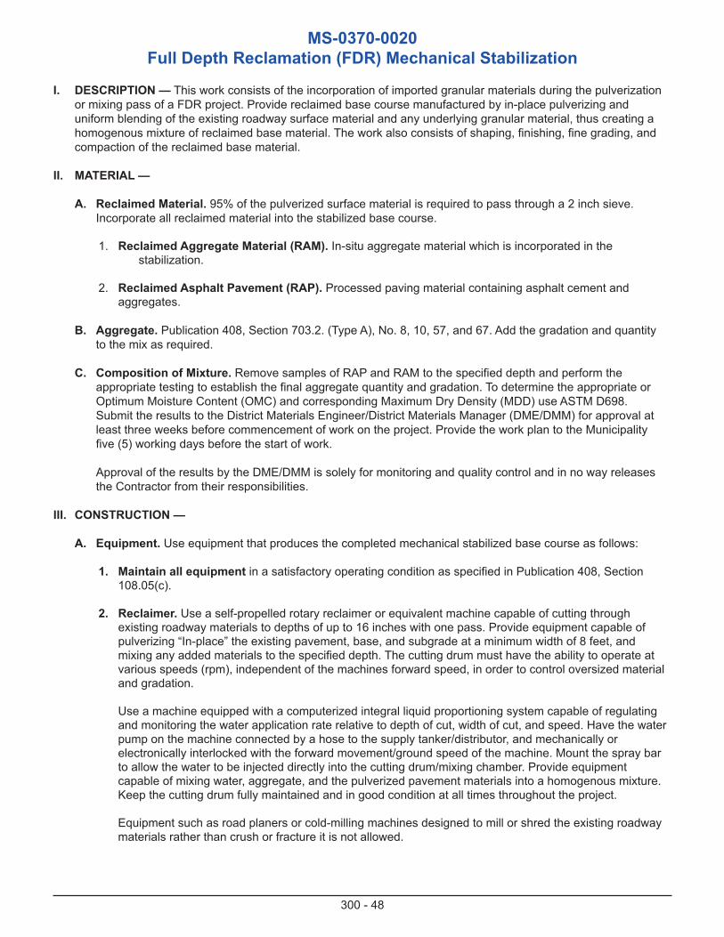
300 - 48
MS-0370-0020Full Depth Reclamation (FDR) Mechanical Stabilization
I. DESCRIPTION — This work consists of the incorporation of imported granular materials during the pulverization or mixing pass of a FDR project. Provide reclaimed base course manufactured by in-place pulverizing and uniform blending of the existing roadway surface material and any underlying granular material, thus creating a homogenous mixture of reclaimed base material. The work also consists of shaping, finishing, fine grading, and compaction of the reclaimed base material.
II. MATERIAL —
A. Reclaimed Material. 95% of the pulverized surface material is required to pass through a 2 inch sieve. Incorporate all reclaimed material into the stabilized base course.
1. Reclaimed Aggregate Material (RAM). In-situ aggregate material which is incorporated in thestabilization.
2. Reclaimed Asphalt Pavement (RAP). Processed paving material containing asphalt cement and aggregates.
B. Aggregate. Publication 408, Section 703.2. (Type A), No. 8, 10, 57, and 67. Add the gradation and quantity to the mix as required.
C. Composition of Mixture. Remove samples of RAP and RAM to the specified depth and perform the appropriate testing to establish the final aggregate quantity and gradation. To determine the appropriate or Optimum Moisture Content (OMC) and corresponding Maximum Dry Density (MDD) use ASTM D698. Submit the results to the District Materials Engineer/District Materials Manager (DME/DMM) for approval at least three weeks before commencement of work on the project. Provide the work plan to the Municipality five (5) working days before the start of work.
Approval of the results by the DME/DMM is solely for monitoring and quality control and in no way releases the Contractor from their responsibilities.
III. CONSTRUCTION —
A. Equipment. Use equipment that produces the completed mechanical stabilized base course as follows:
1. Maintain all equipment in a satisfactory operating condition as specified in Publication 408, Section 108.05(c).
2. Reclaimer. Use a self-propelled rotary reclaimer or equivalent machine capable of cutting through existing roadway materials to depths of up to 16 inches with one pass. Provide equipment capable of pulverizing “In-place” the existing pavement, base, and subgrade at a minimum width of 8 feet, and mixing any added materials to the specified depth. The cutting drum must have the ability to operate at various speeds (rpm), independent of the machines forward speed, in order to control oversized material and gradation.
Use a machine equipped with a computerized integral liquid proportioning system capable of regulating and monitoring the water application rate relative to depth of cut, width of cut, and speed. Have the water pump on the machine connected by a hose to the supply tanker/distributor, and mechanically or electronically interlocked with the forward movement/ground speed of the machine. Mount the spray bar to allow the water to be injected directly into the cutting drum/mixing chamber. Provide equipment capable of mixing water, aggregate, and the pulverized pavement materials into a homogenous mixture. Keep the cutting drum fully maintained and in good condition at all times throughout the project.
Equipment such as road planers or cold-milling machines designed to mill or shred the existing roadway materials rather than crush or fracture it is not allowed.
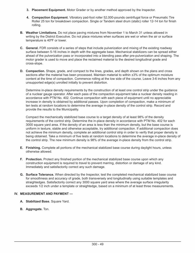
300 - 49
3. Placement Equipment. Motor Grader or by another method approved by the Inspector.
4. Compaction Equipment. Vibratory pad-foot roller 52,000-pounds centrifugal force or Pneumatic Tire Roller 25 ton for breakdown compaction. Single or Tandem steel drum (static) roller 12-14 ton for finish rolling.
B. Weather Limitations. Do not place paving mixtures from November 1 to March 31 unless allowed in writing by the District Executive. Do not place mixtures when surfaces are wet or when the air or surface temperature is 40ºF or lower.
C. General. FDR consists of a series of steps that include pulverization and mixing of the existing roadway surface between 5-16 inches in depth with the aggregate base. Mechanical stabilizers can be spread either ahead of the pulverization pass or incorporated into a blending pass after pre-pulverization and shaping. The motor grader is used to move and place the reclaimed material to the desired longitudinal grade and cross-slope.
D. Compaction. Shape, grade, and compact to the lines, grades, and depth shown on the plans and cross sections after the material has been processed. Maintain material to within ±3% of the optimum moisture content at the time of compaction. Commence rolling at the low side of the course. Leave 3-6 inches from any unsupported edge(s) unrolled initially to prevent distortion.
Determine in-place density requirements by the construction of at least one control strip under the guidance of a nuclear gauge operator. After each pass of the compaction equipment take a nuclear density reading in accordance with PTM No. 402. Continue compaction with each piece of equipment until no appreciable increase in density is obtained by additional passes. Upon completion of compaction, make a minimum of ten tests at random locations to determine the average in-place density of the control strip. Record and provide the results to the Municipality.
Compact the mechanically stabilized base course to a target density of at least 98% of the density requirements of the control strip. Determine the in-place density in accordance with PTM No. 402 for each 3000 square yard area. If the density of an area is less than the minimum density, but the base course is uniform in texture, stable and otherwise acceptable, try additional compaction. If additional compaction does not achieve the minimum density, complete an additional control strip in order to verify that proper density is being obtained. Take a minimum of five tests at random locations to determine the average in-place density of the control strip. The new minimum density is 98% of the average in-place density from the control strip.
E. Finishing. Complete all portions of the mechanical stabilized base course during daylight hours, unless otherwise allowed.
F. Protection. Protect any finished portion of the mechanical stabilized base course upon which any construction equipment is required to travel to prevent marring, distortion or damage of any kind. Immediately and satisfactorily correct any such damage.
G. Surface Tolerance. When directed by the Inspector, test the completed mechanical stabilized base course for smoothness and accuracy of grade, both transversely and longitudinally using suitable templates and straightedges. Satisfactorily correct any 3000 square yard area where the average surface irregularity exceeds 1/2 inch under a template or straightedge, based on a minimum of at least three measurements.
IV. MEASUREMENT AND PAYMENT —
A. Stabilized Base. Square Yard.
B. Aggregate. Ton.
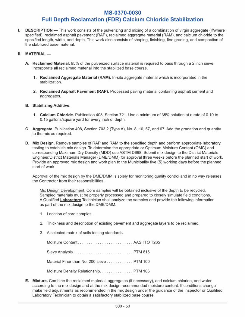
300 - 50
MS-0370-0030Full Depth Reclamation (FDR) Calcium Chloride Stabilization
I. DESCRIPTION — This work consists of the pulverizing and mixing of a combination of virgin aggregate (if/where specified), reclaimed asphalt pavement (RAP), reclaimed aggregate material (RAM), and calcium chloride to the specified length, width, and depth. This work also consists of shaping, finishing, fine grading, and compaction of the stabilized base material.
II. MATERIAL —
A. Reclaimed Material. 95% of the pulverized surface material is required to pass through a 2 inch sieve. Incorporate all reclaimed material into the stabilized base course.
1. Reclaimed Aggregate Material (RAM). In-situ aggregate material which is incorporated in the stabilization.
2. Reclaimed Asphalt Pavement (RAP). Processed paving material containing asphalt cement and aggregates.
B. Stabilizing Additive.
1. Calcium Chloride. Publication 408, Section 721. Use a minimum of 35% solution at a rate of 0.10 to 0.15 gallons/square yard for every inch of depth.
C. Aggregate. Publication 408, Section 703.2 (Type A), No. 8, 10, 57, and 67. Add the gradation and quantity to the mix as required.
D. Mix Design. Remove samples of RAP and RAM to the specified depth and perform appropriate laboratory testing to establish mix design. To determine the appropriate or Optimum Moisture Content (OMC) and corresponding Maximum Dry Density (MDD) use ASTM D698. Submit mix design to the District Materials Engineer/District Materials Manager (DME/DMM) for approval three weeks before the planned start of work. Provide an approved mix design and work plan to the Municipality five (5) working days before the planned start of work.
Approval of the mix design by the DME/DMM is solely for monitoring quality control and in no way releases the Contractor from their responsibilities.
Mix Design Development. Core samples will be obtained inclusive of the depth to be recycled. Sampled materials must be properly processed and prepared to closely simulate field conditions. A Qualified Laboratory Technician shall analyze the samples and provide the following information as part of the mix design to the DME/DMM.
1. Location of core samples.
2. Thickness and description of existing pavement and aggregate layers to be reclaimed.
3. A selected matrix of soils testing standards.
Moisture Content. . . . . . . . . . . . . . . . . . . . . . . . . AASHTO T265
Sieve Analysis . . . . . . . . . . . . . . . . . . . . . . . . . . . PTM 616
Material Finer than No. 200 sieve . . . . . . . . . . . . PTM 100
Moisture Density Relationship. . . . . . . . . . . . . . . PTM 106
E. Mixture. Combine the reclaimed material, aggregates (if necessary), and calcium chloride, and wateraccording to the mix design and at the mix design recommended moisture content. If conditions change make field adjustments as recommended in the mix design under the guidance of the Inspector or Qualified Laboratory Technician to obtain a satisfactory stabilized base course.
300 - 51
III. CONSTRUCTION —
A. Equipment. Use equipment that will produce the completed chemical stabilized base course as follows:
1. Use equipment capable of automatically metering liquids with a variation of not more than ±2% by mass (weight) of liquids. Calibrate before use.
2. Maintain all equipment in a satisfactory operating condition as specified in Publication 408, Section 108.05(c).
3. Reclaimer. Use a self-propelled rotary reclaimer or equivalent machine capable of cutting through existing roadway material to depths of up to 16 inches with one pass. Provide equipment capable of pulverizing “In-place” the existing pavement base and subgrade at a minimum width of 8 feet, and mixing any added materials to the specified depth. The cutting drum must have the ability to operate at various speeds (rpm), independent of the machines forward speed, in order to control oversized material and gradation.
Use a machine equipped with a computerized integral liquid proportioning system capable of regulating and monitoring the liquid application rate relative to depth of cut, width of cut, and speed. Have the liquid pump on the machine connected by a hose to the supply tanker/distributor, and mechanically or electronically interlocked with the forward movement/ground speed of the machine. Mount the spray bar to allow the liquid to be injected directly into the cutting drum/mixing chamber. Provide equipment capableof mixing Calcium Chloride and the pulverized pavement materials into a homogenous mixture. Keep the cutting drum fully maintained and in good condition at all times throughout the project.
Equipment such as road planers or cold-milling machines designed to mill or shred the existing roadway materials rather than crush or fracture it is not allowed.
4. Placement Equipment. Motor Grader or by another method approved by the Inspector.
5. Compaction Equipment. Vibratory pad-foot roller 52,000-pounds centrifugal force or Pneumatic Tire Roller 25 ton for breakdown compaction. Single or tandem steel drum (static) roller 12-14 ton for finish rolling.
B. Weather Limitations. Do not place paving mixtures from November 1 to March 31, unless allowed in writing by the District Executive. Do not place mixtures when surfaces are wet or when the air or surface temperatureis 40ºF or lower.
C. General. FDR consists of a series of steps that include pulverization and mixing of the existing roadway surface between 5-16 inch in depth with the aggregate base and subgrade soil. Calcium Chloride can be injected through the machines computerized integral liquid proportioning system during the pulverization pass or incorporated into a blending pass after pre-pulverization and shaping. The motor grader is used to move and place the reclaimed material to the desired longitudinal grade and cross-slope.
D. Pulverization/Stabilization/Mixing. Pulverize and mix the roadway material to a minimum depth of 5 inches. Thoroughly mix the existing roadway materials together at the design specified treatment depth while surface adding or injecting the design specified amount of Calcium Chloride to create a homogenous stabilized mixture. Rough grade to desired cross slope and profile. Apply the designed quantity of calcium chloride and liquid to assure proper compaction.
E. Compaction. Shape, grade and compact to the lines, grades, and depth shown on the plans and cross sections after the material has been processed. The moisture content before compaction should be at or no more than ±3% over Optimum Moisture Content (OMC). Allow the mixture to cure as necessary before rolling. Commence rolling at the low side of the course. Leave 3 to 6 inches from any unsupported edge(s) unrolled initially to prevent distortion.
Determine the in-place density requirements by the construction of at least one control strip under the guidance of a nuclear gauge operator. After each pass of the compaction equipment take a nuclear density reading in accordance with PTM No. 402. Continue compaction with each piece of equipment until no
300 - 52
appreciable increase in density is obtained by additional passes. Upon completion of compaction, make a minimum of ten tests at random locations to determine the average in-place density of the control strip. Record and provide the results to the Municipality.
Compact the Calcium Chloride stabilized base course to a target density of at least 98% of the average in-place density of the control strip. Determine the in-place density in accordance with PTM No. 402 for each 3,000 square yard area. If the density of an area is less than the minimum density but the base course is uniform in texture, stable and otherwise acceptable, try additional compaction. If additional compaction does not achieve the minimum density complete an additional control strip in order to verify that proper density is being obtained. Take a minimum of five tests at random locations to determine the average in-place densityof the control strip. The new minimum density is 98% of the average in-place density.
If it is determined that the contractor is achieving the target density with minimum compactive effort, the Inspector may require a new control strip to verify or establish a new target density.
If the completed Calcium Chloride stabilized base course is unacceptable for any reason do not continue construction until the cause of the deficiency (ies) is determined and corrected.
F. Finishing. Complete all portions of the calcium chloride stabilized base course during daylight hours, unless otherwise allowed.
G. Protection. Protect any finished portion of the calcium chloride stabilized base course upon which anyconstruction equipment is required to travel to prevent marring, distortion or damage of any kind. Immediately and satisfactorily correct any such damage.
H. Surface Tolerance. When directed by the Inspector, test the completed calcium chloride stabilized base course for smoothness and accuracy of grade, both transversely and longitudinally using suitable templates and straightedges. Satisfactorily correct any 3000 square yard area where the average surface irregularity exceeds 1/2 inch under a template or straightedge, based on a minimum of at least three measurements.
I. Curing. Allow the calcium chloride stabilized base course to cure for at least 5 days after final compaction has been completed. Protect the surface from drying.
IV. MEASUREMENT AND PAYMENT —
A. Chemical Stabilized Base. Square Yard.
B. Aggregate. Ton.
C. Calcium Chloride. Gallon.
300 - 53
MS-0370-0035Full Depth Reclamation (FDR) Chemical Stabilization
I. DESCRIPTION — This work consists of pulverizing and mixing a combination of virgin aggregate (if/wherespecified), Reclaimed Asphalt Pavement, Reclaimed Aggregate Material, and Subgrade Material to the specifiedlength, width, and depth. Once pulverized, add the Chemical Stabilizing additives as per Project Mix Design, and mixthe materials together to create a chemically stabilized base course. This work also consists of shaping, finishing, finegrading, and compaction of the reclaimed base material.
II. MATERIAL —
A. Reclaimed Material. 95% of the pulverized surface material is required to pass through a 2-inch sieve.Incorporate all reclaimed material into the stabilized base course.
1. Reclaimed Aggregate Material (RAM). In-situ aggregate material which is incorporated in the stabilization.
2. Reclaimed Asphalt Pavement (RAP). Processed paving material containing asphalt cement and aggregates.
B. Stabilizing Agent.
1. 1. Cement. Publication 408, Section 701. (3 to 8% by weight).1.a Cement Slurry. Pub 408, Section 701 & Pub 242 Appendix J (applied cement 3 to 8% by weight). Portland Cement Slurry must be produced at a concrete plant listed in Bulletin 42 and supplied in Ready Mix Concrete Trucks currently approved by the DME/DMM. Other slurries must be providedin distributor and tanker trucks equipped with a recirculating pump and/or agitation system to preventsettling of the materials before application.1.a.1 Admixtures, Publication 408 Section 711.3
2. *Hydrated Lime. Publication 408, Section 723. (2 to 6% by weight).
3. *Fly Ash. Publication 408, Section 724.2(a). (6 to 14% by weight).
4. Lime Pozzolan. Publication 408, Section 725. (6 to 8% by weight).
* Hydrated Lime or Fly Ash will not be used as a singular additive but will be used as a combination of thetwo. This combination shall be referred to as Lime/Fly Ash (L/FA).
C. Aggregate. Publication 408, Section 703.2 (Type A), No. 8, 10, 57, and 67. Add the gradation and quantity tothe mix as required.
D. Mix Design. Remove samples of RAP and RAM to the specified depth and perform appropriate laboratorytesting to establish mix design. Submit mix design to the District Materials Engineer/District Materials Manager (DME/DMM) for approval three weeks before the planned start of work. Provide an approvedmix design and work plan to the Municipality five (5) working days before the planned start of work.
Approval of the mix design by the DME/DMM is solely for monitoring quality control and in no way releases the Contractor from their responsibilities.
Mix Design Development. Samples must be obtained inclusive of the depth to be recycled. Sampled materials must be properly processed and prepared to closely simulate field conditions. A Qualified Laboratory Technician will analyze the samples and provide the following information as part of the mix design to the DME/DMM.
1. Location of core samples.
2. Thickness and description of existing pavement and aggregate layers to be reclaimed.
300 - 54
3. A selected matrix of soils testing standards.
Moisture Content. . . . . . . . . . . . . . . . . . . . . . . . . AASHTO T265
Sieve Analysis . . . . . . . . . . . . . . . . . . . . . . . . . . . PTM 616*Mechanical and Hydrometer
Particle Size Analysis of Soils . . . . . . . . . . . . . . . AASHTO T88-90*Liquid Limit, Plastic Limit . . . . . . . . . . . . . . . . . . AASHTO T89
Moisture Density Relationship. . . . . . . . . . . . . . . PTM 106
Unconfined Compression . . . . . . . . . . . . . . . . . . AASHTO T208
Material Finer than No. 200 Sieve. . . . . . . . . . . . PTM 100* To be performed only if more than 20% of the underlying subgrade is to be included in the chemically stabilized layer.
1. Strength Requirements —
A. Cement. Make, cure, and test three unconfined compressive strength specimens of FDR material andCement in accordance with ASTM 1633, method A. Wrap the specimens in plastic wrap, seal in an airtight, moisture proof bag and cure the test specimens for a period of 7 days. For the final mix design,the required amount of cement will be that which provides an average unconfined compressive strength of the three specimens of:
A minimum unconfined compression value of 200 psi in 7 days and a maximum unconfined compressionvalue of 500 psi in 7 days for roads that are designed with a minimum of a 3-inch pavement overlay.
A minimum unconfined compression value of 300 psi in 7 days and a maximum unconfined compressionvalue of 500 psi in 7 days is required for roads that are to be Surface Treated or overlaid with less than 3 inches of pavement.
B. Lime/Fly Ash (L/FA), Lime Pozzolan and combinations there-of. Make, cure, and test three unconfined compressive strength specimens of FDR material and L/FA or Lime Pozzolan in accordancewith ASTM 1633, method A. Wrap the specimens in plastic wrap, seal in an airtight, moisture proof bagand cure the test specimens for a period of 7 days at 104°F before testing. For the final mix design, the required amount of L/FA or Lime Pozzolan will be that which provides an average unconfined compressive strength of the three specimens of at least 200 psi.
C. Mixture. Combine the reclaimed material, aggregates (if necessary), stabilizing additive(s), and water according to the mix design and at the mix design recommended moisture content. If conditions change,make field adjustments as recommended in the design under the guidance of the Inspector and Qualified Laboratory Technician to obtain a satisfactory Stabilized Base Course.
III. CONSTRUCTION —
A. Equipment. Use equipment that will produce the completed chemical stabilized base course as follows:
1. Use equipment capable of automatically metering liquids with a variation of not more than ±2% by mass (weight) of liquids. Calibrate before use.
2. Ready Mix concrete trucks from an approved Bulletin 42 producer must be used to apply cement slurry.
3. Maintain all equipment in a satisfactory operating condition as specified in Publication 408, Section 108.05(c).
300 - 55
4. Reclaimer. Use a self-propelled, traveling rotary reclaimer or equivalent machine capable of cutting through existing roadway material to depths of up to 16 inches with one pass. The equipment will be capable of pulverizing “In-place” the existing pavement, base and subgrade at a minimum width of 8 feetand mixing any added materials to the specified depth. The cutting drum must have the ability to operate at various speeds (rpm), independent of the machines forward speed, in order to control oversized material and gradation.
Use a machine equipped with a computerized integral liquid proportioning system capable of regulating andmonitoring the water application rate relative to depth of cut, width of cut, and speed. Have the water pump on the machine connected by a hose to the supply tanker/distributor, and mechanically or electronically interlocked with the forward movement/ground speed of the machine. Mount the spray bar to allow the water to be injected directly into the cutting drum/mixing chamber. Provide equipment capableof mixing water, dry additives, and the pulverized pavement materials into a homogenous mixture. Keep the cutting drum fully maintained and in good condition at all time throughout the project.
5. Equipment such as road planers or cold-milling machines designed to mill or shred the existing roadway materials rather than crush or fracture it is not allowed.
6. Placement Equipment. Motor Grader or by another method approved by the Inspector.
7. Compaction Equipment. Vibratory pad-foot roller 52,000-pounds centrifugal force or Pneumatic Tire Roller 25 ton for breakdown compaction. Single or tandem steel drum (static) roller 12-14 ton for finishrolling.
B. Weather Limitations. Do not place paving mixtures from November 1 to March 31 unless allowed in writing by the District Executive. Do not place mixtures when surfaces are wet or when the air or surface temperature is 40ºF and falling. Cement Slurry with accelerating admixtures can be used in periods of cooler temperatures with the written approval of the DME/DMM. Do not place cement slurry mixtures with accelerating admixtures when the air temperature is anticipated to fall below 35o F within the first 24 hours following placement.
C. General. FDR consists of a series of steps that include pulverization and mixing of the existing roadway surface between 5-16 inch in depth with the aggregate base. The motor grader is used to move and place the reclaimed material to the desired longitudinal grade and cross-slope.
D. Pulverization/Shaping. Before the application of any stabilizing additives pulverize the roadway materials to the depth specified by the project mix design. Shape to within 3/4 inch of irregularity to the lines,grades and/or cross-slope of the proposed roadway and compacted until no further densification is achieved. Water will be added to the pulverized material to adjust the moisture content to at least Optimum Moisture Content (OMC), but no more than ±3% over OMC. Addition of this water can be done through the machines liquid additive system and/or through top watering. After acceptance by the DME/DMM the additive spreading and mixing will be done as described below.
1. Additive Application.
a. Cement, Lime/Fly Ash (L/FA), Lime Pozzolan and combinations there-of. Upon completion of the pulverization pass the stabilizing additives previously outlined will be applied at the rate established by the DME/DMM approved project mix design. The additive will be accurately and uniformly spread on the pulverized pavement by using an adjustable rate auger/vane type dry additive distributor. The contractor will provide a 1-square yard of canvas and scale to check the application rate of the spreader. Dry additives will be spread in a manner to minimize dusting. The dry additive will not be applied when the wind conditions in the opinion of the DME/DMM, are such that blowing additives become objectionable to traffic or adjacent property owners. Manual and/or gravity (tail gate) spreading of the additives is unacceptable.
b. Lime or Cement Slurry. If slurries are to be used, the distributor and tanker trucks will be equipped with a recirculating pump and/or agitation system to prevent settling of the materials before application. If the cement slurry is obtained from a Ready Mix Concrete plant the cement slurry must be produced at a concrete plant listed in Bulletin 42 and supplied in Ready Mix Concrete Trucks
300 - 56
currently approved by the DME/DMM. Verify “cement” application rate by calculating the weight of cement contained in the mixer truck and the area covered by the slurry after discharge by the Ready Mix Truck. The cement slurry producer shall supply a written record of the amount of cement, water, and admixture with each load of cement slurry. Evenly and uniformly distribute the cement slurry, over the area of the prepared subgrade, calculated to provide the required application rate.
E. Stabilization/Mixing. Once the additives are applied thoroughly mix the additives and pulverized pavement together at the design specified treatment depth while simultaneously injecting any additional water needed(if any) through the machines computerized integral liquid proportioning system to create a homogenous mixture. The moisture content before compaction must be at or no more than 3% over OMC.
F. Compaction. Shape, grade and compact to the lines, grades, and depth shown on the plans and cross sections after the material has been processed. The moisture content before compaction must be at or no more than 3% over OMC. Allow the mixture to cure as necessary before rolling. Commence rolling at the low side of the course. Leave 3 to 6 inches from any unsupported edge(s) unrolled initially to prevent distortion.
Determine the in-place density requirements by the construction of at least one control strip under the guidance of a nuclear gauge operator. After each pass of the compaction equipment take a nuclear density reading in accordance with PTM No. 402. Continue compaction with each piece of equipment until no appreciable increase in density is obtained by additional passes. Upon completion of compaction, make a minimum of ten tests at random locations to determine the average in-place density of the control strip.Record and provide results to the Municipality.
Compact the chemically stabilized base course to a target density of at least 98% of the average in-place density of the control strip. Determine the in-place density in accordance with PTM No. 402 for each 3000 square yard area. If the density of an area is less than the minimum density, but the base course is uniform in texture, stable and otherwise acceptable, try additional compaction.
If additional compaction does not achieve the minimum density, complete an additional control strip in orderto verify that proper density is being obtained. Take a minimum of five tests at random locations to determine the average in-place density of the control strip. The new minimum density is 98% of the average in-place density.
If it is determined that the contractor is achieving the target density with minimum compactive effort, the Inspector may require a new control strip to verify or establish a new target density.
If the completed chemically stabilized base course is unacceptable for any reason do not continue construction until the cause of the deficiency (ies) is determined and corrected.
G. Finishing. Complete all portions of the chemical stabilized base course during daylight hours, unless otherwise allowed.
H. Protection. Protect any finished portion of the chemical stabilized base course upon which any construction equipment is required to travel to prevent marring, distortion or damage of any kind. Immediately and satisfactorily correct any such damage.
I. Surface Tolerance. When directed by the Inspector, test the completed chemical stabilized base course for smoothness and accuracy of grade, both transversely and longitudinally using suitable templates and straightedges. Satisfactorily correct any 3000 square yard area where the average surface irregularity exceeds 1/2 inch under a template or straightedge, based on a minimum of at least three measurements.
J. Curing. Do not allow traffic on the newly constructed chemical stabilized base course until it cures unless otherwise directed in writing by the Municipality. Allow the chemical stabilized base course to cure for at least five days after final compaction has been completed. Protect the surface from drying and apply a bituminous prime coat, or DME/DMM approved equivalent over the entire surface within 24 hours of final compaction of the stabilized base course. Apply at a rate of 0.21 gallons per square yard. Use emulsified asphalt meeting the requirements of Publication 408, Section 461.2(a). Where the surface is utilized for maintaining traffic the application of the bituminous material shall be immediately followed by the application of an approved cover aggregate.

300 - 57
IV. MEASUREMENT AND PAYMENT —
A. Chemical Stabilized Base. Square Yard.
B. Aggregate. Ton.
C. Stabilizing Additives.
1. Cement. Ton.
2. Hydrated Lime. Ton.
3. Fly Ash. Ton.
4. Lime-Pozzolan. Ton.
D. Bituminous Prime Coat. Square Yard or Gallon.
300 - 58
MS-0370-0040Full Depth Reclamation (FDR) Bituminous Stabilization
I. DESCRIPTION — This work consists of the incorporation of bituminous stabilization materials during the pulverization or mixing pass of a FDR project. This work also consists of shaping, finishing, fine grading, and compaction of the reclaimed base material.
II. MATERIAL —
A. Reclaimed Material. 95% of the pulverized surface material is required to pass through a 2 inch sieve. Incorporate all reclaimed material into the stabilized base course.
1. Reclaimed Aggregate Material (RAM). In-situ aggregate material which is incorporated in the stabilization.
2. Reclaimed Asphalt Pavement (RAP). Processed paving material containing asphalt cement and aggregates.
B. Bituminous Material. Add to the mix the type and quantity of bituminous material as determined by the approved mix design. Use bituminous material conforming to the applicable requirements of Bulletin 25. Use one of the following:
1. Emulsified Asphalt. SS-1 (E6A), CSS-1 (E6-C), SS-1h (E-8A), CSS-1h (E-8C), HFMS-2 (E-11-90), HFMS-2s (E-11-150), HFMS-2h (E-11-60). Polymer modified versions of the above materials can be used as necessary, conforming to the requirements in Publication 242, Chapter 5. (1.5 to 4.5% by weight typical).
C. Aggregate. Publication 408, Section 703.2 (Type A), No. 8, 57, and 67. Add the gradation and quantity to the mix as required.
D. Mix Design. Remove samples of RAP and RAM to the specified depth and perform the appropriate laboratory testing to establish the mix design. Guidelines and design process for full depth reclamation are listed in Chapter 2 of Bulletin 27 “Bituminous Concrete Mixtures, Design Procedures and Specifications for Special Bituminous Mixtures.” Determine the theoretical maximum specific gravity according to AASHTO T-209 on the designed mixture at the optimum emulsified asphalt content. Submit the mix design to the District Materials Engineer/District Materials Manager (DME/DMM) for approval three weeks before the start of work. Provide an approved mix design and work plan to the Municipality five (5) working days before the start of work.
Approval of the mix design by the DME/DMM is solely for monitoring quality control and in no way releases the Contractor from their responsibilities.
F. Mixture. Combine the reclaimed material, aggregates (if necessary), and bitumen, in such proportions that the total aggregate and bitumen in the reclaimed mix conform to the requirements and composition specified in the mix design with the recommended optimum moisture and emulsion content. When composition varies sufficiently, make field adjustments as recommended in the design to obtain completed bituminous stabilized base course, with satisfactory particle coating and optimum compaction.
III. CONSTRUCTION —
A. Equipment. Use equipment that produces the completed bituminous stabilized base course as follows:
1. Use equipment capable of automatically metering liquids with a variation of not more than ±2% by mass (weight) of liquids. Contractor must provide current year calibration to Municipality.
2. Maintain all equipment in a satisfactory operating condition as specified in Publication 408, Section 108.05(c).
3. Reclaimer. Use a self-propelled, traveling rotary reclaimer or equivalent machine capable of cutting
300 - 59
through existing roadway material to depths of up to 16 inches with one pass. The equipment will be capable of pulverizing “In-place” the existing pavement, base, and subgrade at a minimum width of 8 feet, and mixing any added materials to the specified depth. The cutting drum must have the ability to operate at various speeds (rpm), independent of the machines forward speed, in order to control oversized material and gradation.
Use a machine equipped with a computerized integral liquid proportioning system capable of regulating and monitoring the liquid application rate relative to depth of cut, width of cut, and speed. Have the liquid pump on the machine connected by a hose to the supply tanker/distributor, and mechanically or electronically interlocked with the forward movement/ground speed of the machine. Mount the spray bar to allow liquids to be injected directly into the cutting drum/mixing chamber. Provide equipment capable of mixing liquids, dry additives, and the pulverized pavement materials into a homogenous mixture. Keep the cutting drum fully maintained and in good condition at all times throughout the project.
Equipment such as road planers or cold-milling machines designed to mill or shred the existing roadway material rather than crush or fracture it is not allowed.
4. Placement Equipment. Motor Grader or by another method approved by the Inspector.
5. Compaction Equipment. Vibratory pad-foot roller 52,000-pounds centrifugal force or Pneumatic Tire Roller 25 ton for breakdown compaction. Single or tandem steel drum (static) roller 12-14 ton for finish rolling.
B. Weather Limitations. Do not place base course from September 1 to April 30 in Districts 1-0, 2-0, 3-0, 4-0, 9-0, and 10-0; and from October 1 to April 1 in all other districts. With written approval of the District Executive, the Contractor may place base course when no freezing temperatures occur for 24 hours before paving and when the project ambient temperature is 45ºF and rising.
C. General. FDR consists of a series of steps that include pulverization and mixing of the existing roadway surface between 5-16 inches in depth with the aggregate base and subgrade soil. Bituminous stabilizers will be incorporated during a blending pass after pre-pulverization and shaping. The motor grader is used to move and place the reclaimed material to the desired longitudinal grade and cross-slope.
D. Mixing. Maintain adequate total liquids to ensure total mixing of the reclaimed material and aggregate (if required) with the bituminous material. Add liquid to the surface by a calibrated meter as necessary to aid in mixing and compaction.
Upon completion of the pulverization pass, Asphalt Emulsion will be applied at the rate established by the approved mix design. Asphalt Emulsion will be injected through the machines computerized integral liquid proportioning system with a variation of not more than ±2% by mass (weight) of liquids. Extreme care must be taken to verify that material usage/yield is accurate.
Measure the milling depth at the time of pulverization. Make at least one measurement for each 3000-square yard of work done and record the measurements to ensure that the specified milling depth is met. Correct or satisfactorily replace any section deficient 1/2 inch or more from the specified depth.
E. Compaction. Shape, grade, and compact to the lines, grades, and depth shown on the plans and cross sections after the material has been processed. Maintain material to within ±3% optimum and the optimum moisture content at the time of compaction. Commence rolling at the low side of the course. Leave 3-6 inches from any unsupported edge(s) unrolled initially to prevent distortion.
Determine in-place density requirements by the construction of at least one control strip under the guidance of a nuclear gauge operator. After each pass of the compaction equipment take a nuclear density reading in accordance with PTM No. 402. Continue compaction with each piece of equipment until no appreciable increase in density is obtained by additional passes. Upon completion of compaction, make a minimum of ten tests at random locations to determine the average in-place density of the control strip. Record and provide results to the Municipality.
Compact the bituminous stabilized base course to a target density of at least 98% of the average in-place density of the control strip. Determine the in-place density in accordance with PTM No. 402 for each 3000
300 - 60
square yard area. If the density of an area is less than the minimum density, but the base course is uniform in texture, stable, and otherwise acceptable, try additional compaction. If additional compaction does not achieve the minimum density, complete an additional control strip in order to verify that proper density is being obtained. Take a minimum of five tests at random locations to determine the average in-place density of the control strip. The new minimum density is 98% of the average in-place density.
If it is determined that the contractor is achieving the target density with minimum compactive effort, the Inspector may require a new control strip to verify or establish a new target density.
If the completed bituminous stabilized base course is unacceptable for any reason, do not continue construction until the cause of the deficiency (ies) is determined.
F. Finishing. Complete all portions of the bituminous stabilized base course during daylight hours, unless otherwise allowed.
G. Protection. Protect any finished portion of the bituminous stabilized base course upon which any constructionequipment is required to travel to prevent marring, distortion or damage of any kind. Immediately and satisfactorily correct any such damage.
H. Surface Tolerance. When directed by the Inspector, test the completed bituminous stabilized base course for smoothness and accuracy of grade, both transversely and longitudinally using suitable templates and straightedges. Satisfactorily correct any 3000 square yard area where the average surface irregularity exceeds 1/2 in. under a template or straightedge, based on a minimum of at least three measurements.
I. Curing. Do not allow traffic on the newly constructed bituminous stabilized base course until it cures unless otherwise directed in writing by the Municipality. Allow the bituminous stabilized base course to cure for at least 5 days after final compaction has been completed. If excessive raveling is present, apply a bituminous prime coat over the affected area. The rate of application for bituminous material will be up to 0.21 gallons per square yard). The bituminous material will be emulsified asphalt meeting the requirements of Publication 408, Section 461.2(a). Final surfacing will not take place until the stabilized material moisture content is within 2% of the pulverized pavement in-situ moisture content.
IV. MEASUREMENT AND PAYMENT —
A. Bituminous Stabilized Base. Square Yard.
B. Aggregate. Ton.
C. Bituminous Material. Gallon.
D. Bituminous Prime Coat. Square Yard or Gallon.

Section 400 Incidental Construction and Materials

MS-0420-0010Small Diameter Pipe
I. DESCRIPTION — This work is construction or reconstruction and cleaning of 6 inch to 18 inch diameter pipe culverts, and storm drains; including the direct design, manufacturing and testing of reinforced concrete.
II. MATERIAL —
A. Pipes. Publication 408, Section 601 and Comply with the following:
1. Certification. MS-447A
2. Size and Type of Pipe. As indicated.
3. Reinforced Concrete (RC) Pipe, Metal Pipe, Thermoplastic Pipes.
3.a Round and Reinforced Concrete Pipe. Provide RC pipe in accordance to BD-636M, (BD-636), Appendix H of PENNDOT Design Manual Part 4M (Part 4) and the Pennsylvania Installation Direct Design (PAIDD) computer program.
III. CONSTRUCTION — As shown on the Standard Drawings and as follows:
A. General. Provide 6 inch minimum cover from subgrade to pipe barrel. Construct the embankment to 4 feet above the top of pipe elevation or to subgrade, whichever is less, before excavating for the pipe. Hauling will not be permitted over pipe with less than 4 feet of cover. Where running water is encountered and cannot be diverted, provide an acceptable temporary pipe or other structure prior to placing embankment, or as otherwise directed.
Cover Requirements. Pipes with cover between 6 inches and 12 inches must be approved by a registered professional engineer or a PENNDOT engineer knowledgeable in drainage design. Pipes with cover greater than 12 inches measured from top of pipe to top of rigid pavement or to bottom of flexible pavement shall be designed in accordance with the governing material specification.
Reinforced Concrete Pipe. A cover of 12 inches shall be the minimum for Reinforced Concrete Pipe.
Ductile Iron Pipe. Ductile Iron Pipe with cover measuring between 12 inches and 30 inches shall be approved by an engineer prior to installation. Ductile Iron Pipe Research Association (DIPRA)PUBLICATION Truck Loads on Pipes Buried at Shallow Depths may be used as a supplement to AWWA C150 when designing pipes for cover between 12 inches and 30 inches. Corrugated Metal Pipe. A cover of 12 inches shall be the minimum for Corrugated Metal Pipes.
B. Trench and Bedding. Excavate trench and construct bedding as shown on the Standard Drawings.
C. Laying Pipe. Lay pipe as shown on the Standard Drawings before constructing base course or pavement. Lay pipe with bells or grooves up grade. Begin placement of the pipe at the outlet end and continue towards the inlet end, unless otherwise directed.
Control the pipe alignment and grade with suitable string lines, with an electronic laser beam system, or by other acceptable methods.
Camber the grade line to offset anticipated settlement due to the height of embankment and bedding used, if directed.
Lay pipe, except interlocking style and pipe joined with bands, with mortared joints. Before placing succeeding pipe sections, place mortar or an approved joint material on the lower half of the joint, to bring theinner surface of the abutting pipe flush with the previously placed section, such that the flow of water is not obstructed in any manner. Before placing mortar, wet the pipe with as much water as it will readily absorb.
400 - 1

400 - 2
Fill the outside of bell and spigot pipe joints with mortar flush with the bell end. Fill tongue-and-groove pipe joints flush with the pipe's outside surface. On the inside of the pipe, fill the lower half of the joint flush with mortar. Backfilling may proceed immediately after mortaring joints, provided the operation does not cause joint damage, maintains pipe in proper alignment and grade, and provides satisfactory curing conditions for mortar. When permitted, either a preformed joint or caulking compound of an acceptable type may be used in place of mortar to join pipe sections.
On straight-line pipe placements, join pipe sections within 3/4 inch per foot of inside diameter or 1 inch, whichever is less. Join pipes placed on a radius to within these tolerances as measured at a point halfway up the pipe, string line, along the interior of the curve. For pipe runs placed on curves with a radius less than 765 yards (greater than 2 degrees, 30 minutes) use shorter lengths of precast pipe to minimize the joint gap.
When pipes are protected by endwalls or connected with drainage structures, place exposed pipe end within cast-in-place wall or cut off flush with precast structure face and finish with mortar, as directed. Provide satisfactory connections to existing drainage structures.
Coat all aluminum surfaces that will be embedded into concrete with one coat of zinc chromate primer, or a coat of bituminous paint. Allow coating to dry completely before placement of concrete.
D. Elongation of Metal Pipes. When indicated, elongate metal pipe vertically 5%, using acceptable shop methods. Elongate coated pipe by acceptable shop methods only. Satisfactorily repair coating damaged by elongation procedures.
E. Backfilling Trench. After the pipe is laid, backfill the trench as shown on the Standard Drawings. Place material in 4 inch layers. However, 8 inch layers will be permitted when using vibratory compaction equipment. Compact each layer of backfill to the density shown on the Standard Drawings to a height of 4 feet above the top of the pipe, for the full trench width. Use mechanical tampers or other acceptable compaction equipment that will not damage the pipe. Compact backfill material to the density shown on the Standard Drawing as determined by Standard Proctor Density (SPD). Test as specified in Publication 408, Section 600. Test the coarse aggregate backfill for reinforced concrete pipe before placing remaining backfill.
F. Shored or Trench Box Installation. Construct shored or trench box installation where indicated and as specified in Publication 408, Section 107.08. Construct shored or trench box installation as required for reinforced concrete pipe.
Construct shored or trench box installations for thermoplastic or metal pipe as follows:
1. Unless otherwise directed by the Engineer leave trench sheeting in place to prevent loss of foundation support and backfill materials. When the top of trench sheeting is to be cut off, make the cut 18 inches or more above the crown of the pipe. Leave rangers, whalers, and braces in place as required to support the cut off sheeting and trench wall in the vicinity of the pipe zone. Leave timber sheeting in place. Treat timber sheeting against biological degradation and decay if placed above the ground water table.
2. Do not disturb the installed pipe and its embedment when using movable trench boxes and shields. Do not use movable supports below the top of the pipe backfill pay limit zone unless approved methods for maintaining the integrity and level of compaction of the backfill material are used. Before moving supports, place and compact embedment to sufficient depths to ensure protection of the pipe. Finish placing and compacting the backfill material as supports are moved.
3. If the use of sheeting or other trench wall supports is permitted below the pipe backfill pay limit zone, ensure that pipe, bedding, and backfill materials are not disturbed by support removal. Fill voids left upon removal of supports and compact all material to required densities.
G. Jacked Pipe. Jack pipe by means of conventional tunneling or boring methods, when indicated. Before commencement of this work, submit a complete plan and schedule for pipe installation. Include complete details of sheeting, shoring, and bracing for the protection of facilities above the pipe, as well as materials and equipment pertinent to the jacking operation. Do not proceed with pipe installation until the plan and schedule are accepted.
400 - 3
Do not disturb facilities or cause settlement of the ground above the pipe. Provide free and unobstructed use of facilities above the pipe, without delay or danger to life, equipment, or property. Install pipe immediately following the heading or tunneling excavation. After completion of the jacking operation, fill voids around the pipe with grout placed under pressure. Properly protect the grout for at least 3 days.
Place joint sealant material on concrete pipe in front of the jacking frame. Replace or repair pipe damaged during the jacking operations as directed. If steel casing pipe is used, butt-weld the joints as installation progresses. Make joints watertight.
If it is determined that the pipe installation is being conducted in an unsatisfactory manner, stop this work and place a bulkhead at the heading until an alternate procedure is proposed and accepted.
H. Extension of Existing Pipe. If extensions of pipe culverts or drains are indicated or required, remove the existing endwalls as directed. Cut the existing pipe to a true edge, as required, to make a satisfactory joint. Join the new pipe to the existing pipe or endwalls, using acceptable collars constructed of Class A Concrete or acceptable metal connecting bands. Clean the existing pipe, as specified in Publication 408, Section 600-697. Repair or replace existing pipe damaged during construction.
As an alternate to removing the endwall, if permitted, extend the pipe using a concrete collar for pipe extension, as specified in Publication 408, Section 600-697.
I. Cleaning Existing Pipes. Clean existing pipe culverts, as indicated and as directed, before the start of roadway paving operations. Clean inlets, bridge scuppers and piping, manholes, endwalls, and other drainageappurtenances connected to the pipes, as directed. Clean in an acceptable manner and repair damage resulting from the cleaning operation. Remove any material deposited in inlets during paving operations. Prevent material cleaned from the drainage system from entering streams or other bodies of water, and dispose of this material in a satisfactory manner.
J. Relaid Pipe. Remove and clean existing pipes as indicated, and have them inspected by the Representative. Transport and relay accepted existing pipes at the indicated locations, in the same manner specified for new pipes.
K. Removal and Replacement. Remove and replace pipe that is not true to alignment, shows settlement after installation, or is broken or damaged.
L. Inspection of Pipes. Before final acceptance, inspect all of the following types of installed pipe with total loadapplied. Inspect 18 inch to 30 inch diameter pipes from access points. Provide written documentation of all inspections to the Engineer within 72 hours following each inspection.
1. Concrete Pipes. Inspect concrete pipes for signs of damage including cracks greater than 0.007 inch in width, spalls, damaged or cracked ends, and visible reinforcement. Submit a plan for repair or replacement as specified in Publication 408, Section 600-697 for approval.
2. Metal Pipes. Inspect metal pipes for damage including rust, cracking of coatings, damaged galvanization or lining, loose bolts, and areas of local buckling. Repair damaged coatings according to AASHTO M 36/M 36M and AASHTO M 245/M 245M. Develop a repair or replacement plan as specified in Publication 408, Section 600-697 for damage repairs not covered by AASHTO M 36/M 36M or AASHTO M 245/M 245M, buckling, or other major damage, and submit it for approval.
3. Thermoplastic Pipes. Inspect thermoplastic pipes for cracking and joint separation, and perform deflection testing at least 30 days after the embankment is completed. Perform the deflection testing using either electronic deflectometers, calibrated television or video cameras, properly sized “go, no-go” mandrel, direct measurement by extension rulers or tape measures in pipes that allow safe entry, or otheracceptable devices. Where pipe cannot be physically inspected, perform deflection testing at a minimum. Where deflection is greater than 5% of the unloaded inside diameter of the pipe, or cracking or joint separation is detected, develop a remediation plan in accordance with Publication 408, Section 600-697 and submit it to the Engineer for approval.
400 - 4
M. Remediation. Remedial action may include but is not limited to removal and replacement or an accepted repair procedure.
IV. MEASUREMENT AND PAYMENT —
A. Pipe Culverts and Relaid Pipe Culverts. Linear Foot Measured to the point of centerline intersection of “T,” “Y,” and other branches. Includes the pipe, the bedding material, and the backfill as shown on the Standard Drawings.
Furnishing personnel and equipment for dewatering operations, inspection of pipes, and all remedial measures will be considered incidental to the pipe items.
When the pipe item for shore/trench box is indicated or required; includes placement and removal or keeping in place of shoring, supports, shield systems and trench boxes as specified in Publication 408, Section 600-697.
B. Cement Concrete for Miscellaneous Drainage. Cubic Yard As indicated, for the class specified, for the item indicated. Includes reinforcement when required.
C. Class 1 Excavation. Cubic Yard. Pay limits as shown on the Standard Drawings.
D. Class 2 Excavation. Cubic Yard. Including bedding and anchors.
E. Class 4 Excavation. Cubic Yard
Pay limits as shown on the Standard Drawing for pipe culverts and re-laid pipe culverts. Where inlets are installed, measurement terminates 1 foot from the outside face of the inlet wall.
F. Cleaning Existing Pipe Culverts. Linear Foot Measured from inlets, endwalls, and other drainage appurtenances along the pipe centerline.
Cleaning of pipe culverts having diameters up to and including 36 inches will be paid for under one pay item.
G. Jacked Pipe. Linear Foot. The unit price includes excavation.

400 - 5
MS-0430-0010PVC Storm Sewer Drain
I. DESCRIPTION-This work is the installation of storm sewer drainage structures-drains.
II. MATERIAL- As shown on the Standard Drawing or manufacturer's specification and as follows:
A. Storm Sewer Drain Body. PVC. Provide storm sewer drains from PVC pipe stock using a thermo-moldingprocess to reform the pipe stock to the specified configuration. Form storm sewer drains to provide awatertight connection with the specified pipe system. Meet the mechanical property requirements for PVCdescribed by ASTM D3034.
B. Pipe Connection Stubs. PVC pipe stock. Provide a watertight connection with the specified pipe system.Conform to ASTM D3212 for joints for drain and sewer plastic pipe using flexible elastomeric seals. Meet themechanical property requirements for fabricated fittings described by ASTM D3034 and ASTM F1336.
C. Certification. Certify materials as specified in Publication 408, Section 1 06.03(b) 3.
D. Size. 200 to 760 mm (8 to 30 inch), adapts to pipe sizes 100 to 760 mm (4 to 30 inch). Use sizes indicatedon contract drawing and referenced within the contract specifications.
E. Class AA Cement Concrete. Publication 408, Section 704.
F. Coarse Aggregate. Type Cor better, Publication 408, Section 703.2
G. Miscellaneous Materials
1. Ductile iron grates. ASTM A536 grade 70-50-05.
2. Rubber gaskets. ASTM F477.
Ill. CONSTRUCTION- As shown on the Standard Drawing or manufacturer's specification and as follows, inaccordance with ASTM D2321 :
A. General. Install the storm sewer drain using conventional flexible pipe backfill materials and procedures.
B. Installation. As indicated in Standard Drawing, using connection tee and riser pipe, or PVC drainagestructure as recommended by manufacturer. Excavate storm sewer drain location to depth of connectionpipe. Install connection tee and riser using joint method specified for the pipe system. Use an ASTM F-477gasket on top end of riser pipe to make watertight connection to the storm sewer drain. For corrugated pipeplace gasket into last corrugation of the pipe. Lubricate storm sewer drain bell and pipe gasket. Push pipeinto the drain structure to the seat position. Verify drain depth, level and position; correct as necessary.Backfill the open volume surrounding the storm sewer drain with coarse aggregate. Backfill evenly in 200mm (8 inch) lifts and compact in accordance with ASTM D2321 .
Cut top of riser pipe if required to set top of storm sewer drain to final grade elevation to maintain a one pieceleak-proof structure.
For load rated installations, a concrete slab shall be poured under and around the grate and frame. Theconcrete slab must be designed taking into consideration local soil conditions, traffic loading, and otherapplicable design factors.
For H-25 load rated installations pour a 200 mm (8 inch) thick concrete ring under the grate and frame asrecommended on details provided by the manufacturer.
IV. MEASUREMENT AND PAYMENT-
A. PVC Storm Sewer Drain including Rubber Gasket and Ductile Iron Frame and Grate. Each piece.
B. Cement Concrete for Miscellaneous Drainage. Cubic Meter (Cubic Yard). As indicated, for the classspecified, and item indicated.
C. Coarse Aggregate. Square Meter (Square Yard).
400 - 6
MS-0430-0020PVC Storm Sewer Drain Basin
I. DESCRIPTION — This work is the installation of storm sewer drainage structures—drain basins.
II. MATERIAL — As shown on the Standard Drawing or manufacturer’s specification and as follows:
A. Storm Sewer Drain Basin Body. PVC. Provide storm sewer drain basins from PVC pipe stock using a thermo-molding process to reform the pipe stock to the specified configuration. Form storm sewer drain basins to provide a watertight connection with the specified pipe system.
B. Pipe Connection Stubs. PVC pipe stock. Form connection stubs to provide a watertight connection with the specified pipe system. Conform to ASTM D3212 for joint tightness for drain and sewer plastic pipe using flexible elastomeric seals. Meet mechanical property requirements for fabricated fittings described by ASTM D3034 and ASTM F1336 for pipe bell spigot. Use adapter fitting provided by the basin manufacturer for pipe connections to existing PVC basins.
C. Certification. Materials certified as specified in Publication 408, Section 106.03(b)3.
D. Size. 8 to 30 inch adapts to pipe sizes 4 to 30 inch. Use size indicated on contract drawing and referenced within contract specifications.
E. Class AA Cement Concrete. Publication 408, Section 704.2.
F. Coarse Aggregate. Type C or better, Publication 408, Section 703.2
G. Miscellaneous Materials.
1. Ductile iron grates meeting ASTM A536 grade 70-50-05, 12 inch and 15 inch cast iron frames and ASTM F477 rubber gaskets for watertight water connection to riser pipe – both material types provided by manufacturer. The grates for storm sewer drain basins are ductile iron grates for basin diameters 8, 10, 12, 15, 18, 28, and 30 inch are made specifically for each basin by the manufacturer to provide a round bottom flange that closely matches the diameter of the storm sewer drain basin
2. Provide grates for storm sewer drain basins capable of supporting H-25 wheel loading for heavy-duty traffic or H-10 loading for pedestrian traffic. Hinge 12 inch and 15 inch grates to the frame using pins.
III. CONSTRUCTION —
A. General. Install the PVC storm sewer drain basin using conventional flexible pipe backfill materials and procedures.
B. Installation. Excavate storm sewer drain basin location to depth and place a 6 inch base of crushed stone or other granular material. Set storm sewer drain basin in place and level. Install ASTM F-477 gasket on end of pipe. For corrugated pipe, place gasket into last corrugation of the pipe. Lubricate the storm sewer drain basin bell pipe gasket. Push pipe into the drain basin structure to the seat position. Verify drain basin depth, level and position; correct if necessary. Backfill the open volume surrounding the drain basin with coarse aggregate. Backfill evenly in 8 inch lifts and compact each lift to 90-95% of maximum density in accordance with ASTM D2321. Adjust to final grade elevation by either cutting the drain basin body to required grade or by adding PVC Riser Extensions as provided by the manufacturer. For H-25 load rated installations, pour a 8 to 10 inch thick concrete ring under the grate and frame as recommended on details provided by the manufacturer.

400 - 7
IV. MEASUREMENT AND PAYMENT —
A. PVC Basin. Vertical Foot per each diameter.
B. Cement Concrete for Miscellaneous Drainage. Cubic Yard. As indicated, for the class specified, for the item indicated.
C. Pipe Connection Stubs with Rubber Gasket. Per piece. Varies with size.
D. Frame and Grate. Per Piece. Varies with size.
E. Coarse Aggregate. Square Yard

400 - 8
PVC BASIN - MINIMUM ANGLE CHART FOR PIPE CONNECTIONS
8” Diameter BasinsPipe connection Minimum Angle
Diameters Inches Degrees4 4 704 6 754 8 1006 6 906 8 1158 8 165
10” Diameter BasinsPipe connection Minimum Angle
Diameters Inches Degrees4 4 554 6 704 8 804 10 956 6 756 8 856 10 1058 8 908 10 11510 10 160
12” Diameter BasinsPipe connection Minimum Angle
Diameters Inches Degrees4 4 504 6 554 8 654 10 754 12 856 6 656 8 756 10 856 12 958 8 808 10 888 12 102
10 10 9010 12 11512 12 150
15” Diameter BasinsPipe connection Minimum Angle
Diameters Inches Degrees4 4 424 6 474 8 554 10 624 12 704 15 806 6 556 8 636 10 706 12 756 15 868 8 708 10 768 12 838 15 95
10 10 8210 12 8510 15 10312 12 9012 15 11215 15 150
18” Diameter BasinsPipe connection Minimum Angle
Diameters Inches Degrees4 4 354 6 404 8 454 10 524 12 554 15 654 18 766 6 446 8 516 10 556 12 636 15 726 18 848 8 558 10 638 12 708 15 788 18 90
10 10 7010 12 7510 15 8510 18 9712 12 8212 15 8712 18 10215 15 9015 18 11018 18 150
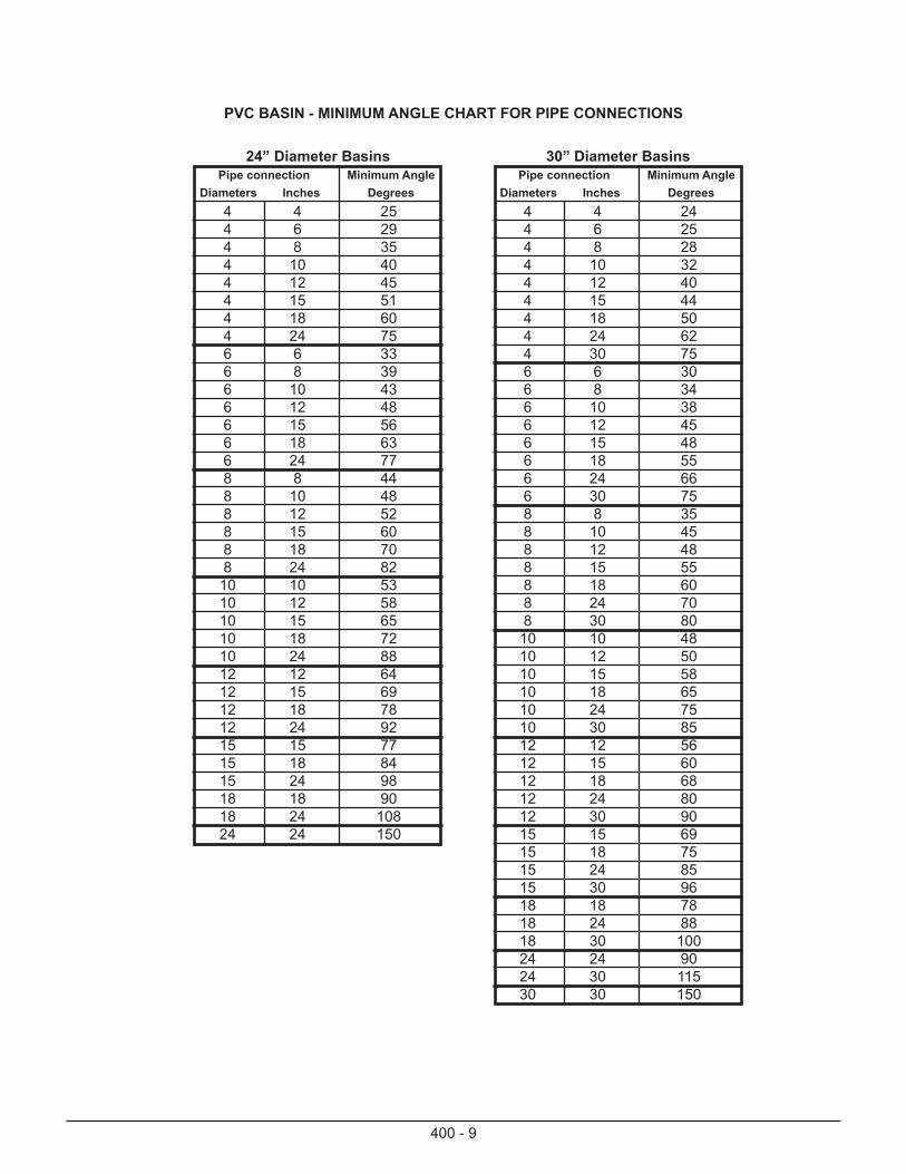
400 - 9
PVC BASIN - MINIMUM ANGLE CHART FOR PIPE CONNECTIONS
24” Diameter BasinsPipe connection Minimum Angle
Diameters Inches Degrees4 4 254 6 294 8 354 10 404 12 454 15 514 18 604 24 756 6 336 8 396 10 436 12 486 15 566 18 636 24 778 8 448 10 488 12 528 15 608 18 708 24 82
10 10 5310 12 5810 15 6510 18 7210 24 8812 12 6412 15 6912 18 7812 24 9215 15 7715 18 8415 24 9818 18 9018 24 10824 24 150
30” Diameter BasinsPipe connection Minimum Angle
Diameters Inches Degrees4 4 244 6 254 8 284 10 324 12 404 15 444 18 504 24 624 30 756 6 306 8 346 10 386 12 456 15 486 18 556 24 666 30 758 8 358 10 458 12 488 15 558 18 608 24 708 30 80
10 10 4810 12 5010 15 5810 18 6510 24 7510 30 8512 12 5612 15 6012 18 6812 24 8012 30 9015 15 6915 18 7515 24 8515 30 9618 18 7818 24 8818 30 10024 24 9024 30 11530 30 150

400 - 10
MS-0440-0020Dust Palliatives
I. DESCRIPTION — This work is the placement of dust palliatives as a surface treatment on existing unpaved roadways or on roadways improved by grading or scarifying to a maximum of 1 inch depth.
II. MATERIAL — APPROVED DUST CONTROL PRODUCTS. Link is for Dust Control Products only.
III. MEASUREMENT AND PAYMENT —Square Yard / Gallon
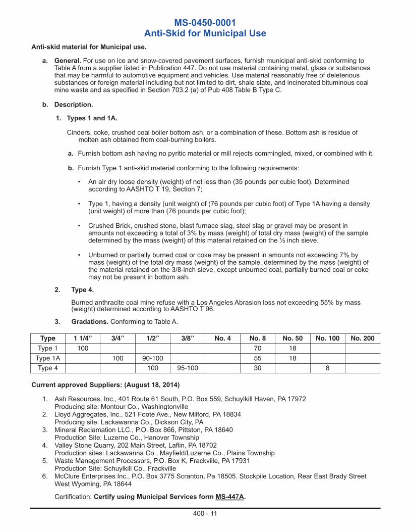
400 - 11
MS-0450-0001Anti-Skid for Municipal Use
Anti-skid material for Municipal use.
a. General. For use on ice and snow-covered pavement surfaces, furnish municipal anti-skid conforming to Table A from a supplier listed in Publication 447. Do not use material containing metal, glass or substances that may be harmful to automotive equipment and vehicles. Use material reasonably free of deleterious substances or foreign material including but not limited to dirt, shale slate, and incinerated bituminous coal mine waste and as specified in Section 703.2 (a) of Pub 408 Table B Type C.
b. Description.
1. Types 1 and 1A.
Cinders, coke, crushed coal boiler bottom ash, or a combination of these. Bottom ash is residue of molten ash obtained from coal-burning boilers.
a. Furnish bottom ash having no pyritic material or mill rejects commingled, mixed, or combined with it.
b. Furnish Type 1 anti-skid material conforming to the following requirements:
• An air dry loose density (weight) of not less than (35 pounds per cubic foot). Determined according to AASHTO T 19, Section 7;
• Type 1, having a density (unit weight) of (76 pounds per cubic foot) of Type 1A having a density (unit weight) of more than (76 pounds per cubic foot);
• Crushed Brick, crushed stone, blast furnace slag, steel slag or gravel may be present in amounts not exceeding a total of 3% by mass (weight) of total dry mass (weight) of the sample determined by the mass (weight) of this material retained on the ½ inch sieve.
• Unburned or partially burned coal or coke may be present in amounts not exceeding 7% by mass (weight) of the total dry mass (weight) of the sample, determined by the mass (weight) of the material retained on the 3/8-inch sieve, except unburned coal, partially burned coal or coke may not be present in bottom ash.
2. Type 4.
Burned anthracite coal mine refuse with a Los Angeles Abrasion loss not exceeding 55% by mass (weight) determined according to AASHTO T 96.
3. Gradations. Conforming to Table A.
Type 1 1/4” 3/4” 1/2” 3/8” No. 4 No. 8 No. 50 No. 100 No. 200Type 1 100 70 18Type 1A 100 90-100 55 18Type 4 100 95-100 30 8
Current approved Suppliers: (August 18, 2014)
1. Ash Resources, Inc., 401 Route 61 South, P.O. Box 559, Schuylkill Haven, PA 17972Producing site: Montour Co., Washingtonville
2. Lloyd Aggregates, Inc., 521 Foote Ave., New Milford, PA 18834Producing site: Lackawanna Co., Dickson City, PA
3. Mineral Reclamation LLC., P.O. Box 866, Pittston, PA 18640 Production Site: Luzerne Co., Hanover Township
4. Valley Stone Quarry, 202 Main Street, Laflin, PA 18702 Production sites: Lackawanna Co., Mayfield/Luzerne Co., Plains Township
5. Waste Management Processors, P.O. Box K, Frackville, PA 17931 Production Site: Schuylkill Co., Frackville
6. McClure Enterprises Inc., P.O. Box 3775 Scranton, Pa 18505. Stockpile Location, Rear East Brady Street West Wyoming, PA 18644
Certification: Certify using Municipal Services form MS-447A.
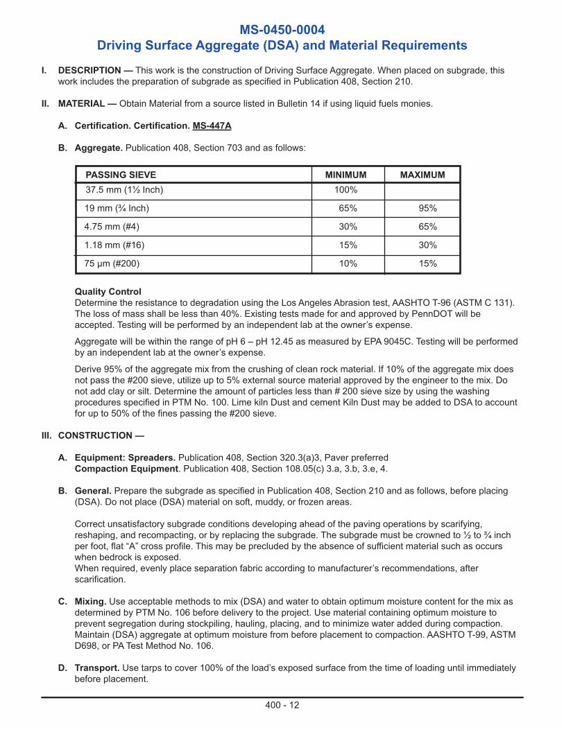
400 - 12
MS-0450-0004Driving Surface Aggregate (DSA) and Material Requirements
I. DESCRIPTION — This work is the construction of Driving Surface Aggregate. When placed on subgrade, this work includes the preparation of subgrade as specified in Publication 408, Section 210.
II. MATERIAL — Obtain Material from a source listed in Bulletin 14 if using liquid fuels monies.
A. Certification. Certification. MS-447A
B. Aggregate. Publication 408, Section 703 and as follows:
Quality ControlDetermine the resistance to degradation using the Los Angeles Abrasion test, AASHTO T-96 (ASTM C 131). The loss of mass shall be less than 40%. Existing tests made for and approved by PennDOT will be accepted. Testing will be performed by an independent lab at the owner’s expense.
Aggregate will be within the range of pH 6 – pH 12.45 as measured by EPA 9045C. Testing will be performed by an independent lab at the owner’s expense.
Derive 95% of the aggregate mix from the crushing of clean rock material. If 10% of the aggregate mix does not pass the #200 sieve, utilize up to 5% external source material approved by the engineer to the mix. Do not add clay or silt. Determine the amount of particles less than # 200 sieve size by using the washing procedures specified in PTM No. 100. Lime kiln Dust and cement Kiln Dust may be added to DSA to account for up to 50% of the fines passing the #200 sieve.
III. CONSTRUCTION —
A. Equipment: Spreaders. Publication 408, Section 320.3(a)3, Paver preferredCompaction Equipment. Publication 408, Section 108.05(c) 3.a, 3.b, 3.e, 4.
B. General. Prepare the subgrade as specified in Publication 408, Section 210 and as follows, before placing (DSA). Do not place (DSA) material on soft, muddy, or frozen areas.
Correct unsatisfactory subgrade conditions developing ahead of the paving operations by scarifying, reshaping, and recompacting, or by replacing the subgrade. The subgrade must be crowned to ½ to ¾ inch per foot, flat “A” cross profile. This may be precluded by the absence of sufficient material such as occurs when bedrock is exposed.When required, evenly place separation fabric according to manufacturer’s recommendations, after scarification.
C. Mixing. Use acceptable methods to mix (DSA) and water to obtain optimum moisture content for the mix as determined by PTM No. 106 before delivery to the project. Use material containing optimum moisture to prevent segregation during stockpiling, hauling, placing, and to minimize water added during compaction. Maintain (DSA) aggregate at optimum moisture from before placement to compaction. AASHTO T-99, ASTM D698, or PA Test Method No. 106.
D. Transport. Use tarps to cover 100% of the load’s exposed surface from the time of loading until immediately before placement.
PASSING SIEVE MINIMUM MAXIMUM37.5 mm (1½ Inch) 100%
19 mm (¾ Inch) 65% 95%
4.75 mm (#4) 30% 65%
1.18 mm (#16) 15% 30%
75 µm (#200) 10% 15%
400 - 13
E. Placement. Place the (DSA) on the subgrade using a paver without causing segregation.
Place (DSA) to a minimum un-compacted depth of 6 inches and a maximum un-compacted depth of 8 inches in one lift. The crown or side slope must range from ½ to ¾ inch per foot, for road widths up to 20 feet.
Material is to be be delivered and placed at optimum moisture content +/- 1% as determined for that particular source. The optimum percentage moisture is to be determined using Proctor Test ASTM D698, procedure C, standard.
F. Compaction. Compaction and Density. Compact DSA to between 95% and 100% of the maximum dry-mass (dry-weight) density, determined according to PTM No. 106, Method B. At locations directed by the owner, determine the in-place density for each 2500 m2 (3,000 square yards), of each layer according to AASHTO T 191 or T 310.
Beginning on the lower or berm side of the crown, begin rolling and work to the top of the crown by overlapping the successive longitudinal passes. Utilize static mode on the initial and downgrade passes. Do not run the roller lengthwise directly over the crown. Compact to specified density requirements, using equipment specified is Publication 408, Section 108.05(c) 3.a, 3.b, 3.e, or 4.
G. Incidental. To fill driving surface areas outside the specified width, such as driveway entrances, turnouts and wider passing lanes, add additional new DSA material to fill to the same depth specified throughout the project. If berm edges do not exist to hold the fill, then place, taper and compact sufficient material to form protective edge berms.
H. Plasticity Index. Material must not exceed Plasticity Index (PI) rating of 6. The laboratory test required for there results is ASTM-D4318-Standard Test Method for Liquid Limit, Plastic Limit, and Plasticity Index of Soils.
IV. MEASUREMENT AND PAYMENT — Ton
400 - 14
MS-0460-0010Use and Design Guidelines for Evaluating and Determining the
Implementation of a Geosynthetically Reinforced Soil – Integrated Bridge System
(GRS-IBS)
OBJECTIVE
The purpose of this document is to provide municipalities with information and guidance towards having engineers evalu-ate the applicability of GRS-IBS for use on their local bridge projects.
INTRODUCTION
GRS technology consists of closely spaced layers of geosynthetic reinforcement and compacted granular fill material.GRS-IBS is a fast, cost-effective method of bridge support that blends the roadway into the superstructure. GRS-IBS in-cludes a Reinforced Soil Foundation (RSF), a GRS abutment, and an Integrated Approach (IA).
I. PROCESS DESCRIPTIONEngineers must utilize the design and construction specifications provided as follows:
A. Federal Highway Administration:
1. FHWA-HRT-11-026: “Geosynthetic Reinforced Soil Integrated Bridge Systems Implementation Guide.”
2. FHWA-HRT-12-051: “Sample Guide Specifications for Construction of Geosynthetic Reinforced Soil-Integrated Bridge Systems (GRS-IBS).”
B. Guidelines in this document provide additional information to FHWA-HRT-11-026 and FHWA-HRT-12-051. In instances where guidelines differ between the sources, this document takes precedence.
C. PennDOT current and applicable design standards, including, but not limited to PennDOT Publication 15M, Design Manual Part 4 on structures.
D. PennDOT standard drawings (PennDOT Publications 72M, 218M, and 219M).
II. GRS-IBS DESIGN GUIDELINES(in accordance with: FHWA-HRT-11-026 and FHWA-HRT-12-051)
A. SITE LIMITATIONS
1. GRS-IBS is limited to bridges with simple span structures.
2. Skew angle for GRS-IBS bridges shall be according to PennDOT Publication 15M based on the limitations of the proposed superstructure type.
3. GRS-IBS is limited to span lengths up to 70 feet.
4. GRS-IBS is limited to bridges with GRS abutment heights up to 30 feet.
5. GRS-IBS is limited to sites with low scour potential.
6. GRS-IBS is limited to maximum stream velocities for all storm events, less than and including the 100 year storm event. Maximum allowable “through structure” stream velocities are:
400 - 15
a. < 7 fps: Conventional GRS construction utilizing standard hollow Concrete Masonry Units (CMUs) with friction connection.
b. 7-10 fps: Complete concrete fill with rebar on standard hollow CMUs.
c. 10-12 fps: Large CMUs (24” x 24” x 72”) with intermediate layers of geotextile wrap-faced at 8” intervals.
7. GRS-IBS is limited to sites with soil pH between 5 and 9.
8. Outlet pipes through the GRS-IBS are not permitted.
B. SITE EVALUATION
A site evaluation shall be performed in accordance with FHWA-HRT-11-026, Section 4.3.2.
C. SCOUR
1. Scour Depth:
a. Footings are to be designed based on the total scour depth obtained from a scour design flood. The scour design flood is defined as a 100 year flood, the flood of record (if available), or the overtopping flood (if less than the 100 year flood), whichever results in the worst-case scour condition in accordance with PennDOT Publication 15M Section 7.2.2.
b. The reinforced soil foundation shall be placed below this calculated depth in accordance with Hydraulic Engineering Circular 18 (HEC-18) -or- PennDOT Publication 15M Section 7.2.4.
2. Scour Protection:
a. A properly designed scour countermeasure shall be placed to protect against local scour in accordance with FHWA-HRT-11-026, Section 4.3.3. Riprap protection shall be sized appropriately for the class of stone specified in accordance with PennDOT Publication 15M Section 7.2.5. It is recommended that CMU blocks which are solid be used at the bottom of the GRS wall for reinforcement, and CMU blocks of a different color can be used to indicate scour as per FHWA-HRT-11-026, Section 6.4.
b. Potential for channel migration shall be evaluated. The effect of lateral channel movement on abutments may be mitigated by providing abutment setback or providing wingwalls that extend beyond the estimated channel migration distance. The RSF shall be protected fromscour. In all cases, wingwall height and length shall be constructed to adequately protect the reinforced fill from channel scour and undermining from surface drainage.
D. BEAM SEAT:
1. The maximum Service I Bearing Pressure on the GRS beam seat shall be limited to 4,000 lb/ft2.
2. A cast in place or precast beam seat with a concrete end diaphragm is required for concrete girders, steel/timber superstructure elements, or other similar superstructures without backwall support.
3. When the use of a superstructure type warrants a beam seat, the superstructure must be properly anchored to the beam seat to prevent lateral movement or uplift of the superstructure.

400 - 16
MS-0460-0011Geosynthetically Reinforced Soil – Integrated Bridge System
(GRS-IBS)
I. DESCRIPTION – This work consists of designing and constructing an Integrated Bridge System (IBS) using Geosynthetically Reinforced Soil (GRS) technology on a Reinforced Soil Foundation (RSF).
II. MATERIAL (in accordance with: FHWA-HRT-11-026 and FHWA-HRT-12-051). Materials must be obtained from a manufacturer listed in Bulletin 15 (unless otherwise noted) for projects with state or Federal funding and conforming to the following requirements:
A. FACING ELEMENTS
1. Concrete Masonry Unit (CMU): PennDOT Publication 408, Section 713, and conforming to thefollowing requirements:
a. Concrete strength of 3000 psi minimum. No additional payment will be made for higher strength concrete.
b. Water absorption limit < 5%.
c. Freeze thaw testing in accordance with ASTM C1262-10.
d. “Standard CMUs”, hollow or solid as required, with nominal dimensions of 8” x 8” x 16”.
2. Large CMU Unit: PennDOT Publication 408, Section 714, and conforming to the following requirements:
a. Solid block with nominal dimensions of 24” x 24” x 72”. Consideration shall be given to the design/installation of necessary temperature and shrinkage reinforcement and any additional reinforcement or lifting devices necessary for handling the large CMU units.
b. Concrete strength of 3000 psi minimum. No additional payment will be made for higher strength concrete.
3. Existing Abutments: GRS structures can be constructed behind existing bridge abutments, subject to PennDOT approval. In these cases, the existing bridge abutments effectively become part of the facing element of the GRS structure. The GRS shall be wrapped-faced using geotextile fabric against the existing abutment in accordance with FHWA-HRT-11-026, Section 7.3.3.
4. Other Facing Elements: Other facing materials may be used with District Bridge Engineer approval.
B. BACKFILL MATERIAL:
1. All backfill material shall consist of sound, crushed, durable particles, fragments of stone gravel free from organic matter or other deleterious material, with a minimum friction angle of 38 degrees.
a. Reinforced Soil Foundation (RSF) Backfill: PennDOT 2A coarse aggregate. All backfill aggregates must be Type A. (PennDOT Publication 408, Section 703.2)
b. GRS Abutment Backfill: AASHTO #8 is the preferred abutment backfill. Backfill may also consist of coarse aggregate conforming to AASHTO #8, #57, #67, or a combination thereof. All backfill aggregates must be Type A. (PennDOT Publication 408, Section 703.2)
c. Integrated Approach Backfill: PennDOT 2A coarse aggregate (PennDOT Publication 408, Section 703.2) -or- Driving Surface Aggregate (DSA). (PennDOT Pub 447, MS-0450-0004)
400 - 17
C. GEOSYNTHETICS (Geotextiles)
1. Geosynthetic Reinforcement in Abutment, Reinforced Soil Foundation and Integrated Approach: Biaxial geotextiles with a minimum Ultimate Tensile Strength = 4,800 lb/ft or as required by design.
a. Woven geotextile strength shall be as determined by ASTM D 4595. Geotextile reinforcement tensile strength at 2 percent strain shall be greater than the calculated required reinforcement strength in the direction perpendicular to the abutment wall face as outlined in FHWA-HRT-11-026, Section 4.3.7.
D. Class A Cement Concrete: Class A cement concrete for use in hollow block wall fill and cast in place coping. (PennDOT Publication 408, Section 704.1)
E. Reinforcement Bars: Deformed rebar of a size and spacing as required by design, epoxy coated or galvanized in accordance with PennDOT Publication 408, Section 1002.
F. Aluminum Flashing: Flashing, such as 4” x 1.5” aluminum fascia or equivalent, may be used to serve as a drip edge under the superstructure to shed potentially corrosive fluids off the dry cast block and to prevent animals from burrowing into the abutment. (Note: Flashing is not Bulletin 15 approved)
G. Preformed Cellular Polystyrene: Preformed Cellular Polystyrene Geotextiles shall conform to PennDOT Publication 408, Section 516.2 and ASTM C578. In addition, it should have expanded polystyrene filler or equivalent, having a compressive strength >10 psi. Total thickness of the foam board shall be 4 inches or greater depending on the abutment height.
H. Asphaltic (bitumen) Coating: An asphaltic coating shall be shop installed on the concrete beam ends where it will be embedded between the GRS abutment and the wing wall to seal the embedded concrete.
J. Scour Countermeasures: Rock Lining as defined in PennDOT Publication 408, Section 850. Rip-rap scour countermeasures shall be sized according to Hydraulic Engineering Circular 23 (HEC-23). Rip-rap size as required by design and as shown on the project drawings.
III. CONSTRUCTION (in accordance with: FHWA-HRT-11-026 (Chapter 7), and FHWA-HRT-12-051, Section 3)
A. Equipment: Use equipment that produces the completed GRS-IBS and maintain all equipment in a satisfactory operating condition as specified in PennDOT Publication 408, Section 108.05(c).
1. Compaction Equipment: Rollers and other compaction equipment as described in PennDOT Publication 408, Section 108.05(c) 3.d, 3.g, 3.h, and 4.
B. Excavation: Construct embankments and/or cut existing grade to the bottom of footing elevations. Excavate and backfill foundation areas as specified in PennDOT Publication 408 Section 204.3 and compact using a mechanical tamper or vibratory compactor. If unsuitable foundation material is encountered, remove all unsuitable material at least 12” or as specified or directed below the bottom of the RSF elevation and backfill with compacted No. 2A Coarse Aggregate as specified or directed. No additional payment shall be made if rock is encountered during excavation.
C. Compaction of Backfill (RSF, Abutment, and Integrated Approach): Hand-operated compaction equipment as specified above is required within 3 ft of the front of the abutment wall face.1. Compaction of Open-Graded Backfill in Abutment: Compact to non-movement or no appreciable
displacement with compaction equipment specified above and assess with visual inspection (minimum of 4 vibratory passes per lift). Abutment backfill is to be placed at a maximum compacted depth of 4 inches per lift.
400 - 18
2. Compaction of Well-Graded Backfill in Reinforced Soil Foundation and Integrated Approach:Compact well-graded backfill to not less than 100% of the determined dry-weight density. Dry-weight density for material in place in the field will be determined, in accordance with Pennsylvania Testing Method (PTM) No. 106, Method B. In-place density or compaction will be determined, in accordance with PTM No. 402 where directed. At the time of compaction, maintain the material's moisture content not more than 2 percentage points above optimum moisture for that material. Backfill is to be placed and compacted in lifts shallow enough to achieve 100% compaction, not to exceed 8 inches (loose) in a single lift.
D. GRS Abutment Facing
1. All CMU block walls shall be constructed with a vertical face.
2. Reinforcement of Facing-wall/Wing-wall Corners for Flows <7 fps
Maximum Stream Velocity:
a. The top three courses of Standard CMU block shall be filled with Class A cement concrete (PennDOT Publication 408, Section 704) with one #4 epoxy coated reinforcement bar of sufficient length to engage all three courses of block, embedded with a minimum of 2” cover, and provided with a cast in place cap in accordance with FHWA-HRT-11-026, Section 7.7.7.
b. All courses of hollow CMU blocks on the facing-wall/wing-wall corners shall be filled as described in Section 2.a above. This shall include a minimum of 3 block columns comprised of the corner unit, and one unit on each side of the corner unit.
3. Reinforcement of Facing-wall/Wing-wall for Flows of 7-10 fps Maximum Stream Velocity:
a. All courses of hollow Standard CMU blocks on the facing-wall and wing-walls shall be filled with Class A cement concrete (PennDOT Publication 408, Section 704), #4 epoxy coated reinforcement bars of sufficient length to engage all courses of block, and embedded with a minimum of 2” cover and provided with a cast in place cap in accordance with FHWA-HRT-11-026, Section 7.7.7.
4. Construction of Facing-wall/Wing-wall for Flows of 10-12 fps Maximum Stream Velocity:
a. Large CMUs (24” x 24” x 72”) shall be used. In addition to horizontal geotextile layers between blocks, two additional intermediate layers of geotextile shall be used behind each block, wrap-faced against the GRS wall so that geotextile spacing is at 8” intervals.
E. Site Drainage
All GRS structures shall include consideration for surface drainage both during and after construction in accordance with FHWA-HRT-11-026, Section 7.1.1 and Section 8.2.
IV. MEASUREMENT AND PAYMENT – Lump Sum. Includes all excavation required for GRS-IBS placement, the Reinforced Soil Foundation (RSF), the GRS abutments, the integrated approach, geotextile, backfill material, CMUs, and scour protection. Does not include the beam seat (when required), superstructure, removal of the existing structure as defined in the contract drawings, temporary support and excavation systems if required, dewatering and other erosion and sedimentation control measures, stream diversion, maintenance and protection of traffic, or approach roadway items.

400 - 19
MS-0460-0020 Use and Design Guidelines for Timber Slab Span Bridge Superstructure
OBJECTIVE
The purpose of this document is to provide municipalities with information and guidance towards having engineers develop contract documents regarding fabrication specifications and installation criteria for a timber bridge superstructure.
INTRODUCTION
Timber bridge superstructures can come in a variety of configurations. These guidelines were developed with pressuretreated dowel laminated timber slab span structures in mind but can be modified for use on other timber structure types.
I. PROCESS DESCRIPTION
Engineers must utilize the design and construction specifications provided as follows:
A. American Association of State Highway and Transportation Officials (AASHTO)
1. Manual for Assessing Safety Hardware (MASH)
2. LRFD Bridge Design Specifications.
B. PennDOT current and applicable design standards, including, but not limited to
1. Design Manual Part 4: Structures (Publication 15M)
2. Design Manual Part 2: Highway Design (Publication 14M)
3. Bridge Safety Inspection Manual (Publication 238M)
4. Specifications (Publication 408)
C. PennDOT standard drawings (PennDOT Publications 6M, 218M, and 219M)
D. Guidelines in this document provide additional information to the above references. In instances where guidelines differ between the sources, this document shall take precedence.
E. It is the design engineer’s responsibility to review and modify, if necessary, the design guidelines and/or specifications herein based on project requirements and site conditions.
II. DESIGN GUIDELINES
A. GENERAL
1. The bridge design shall include loading, substructure configuration, superstructure configuration, railings, barriers, connections, approaches and other structural features of the bridge. Design procedures, analysis, and safety factors shall be in accordance with AASHTO LRFD Bridge Design Specifications as supplemented by Pennsylvania Department of Transportation Design Manual Part 4: Structures (DM-4)
2. The design life of the timber bridge superstructure, including hardware and appurtenances, shall be 50 years minimum.
3. Design of the bridge substructure and superstructure shall include an evaluation of AASHTO and DM-4 LRFD load combinations.
400 - 20
4. Bridge deflection under 125% of the larger of 1) one design vehicle as specified in AASHTO 3.6.1.2.2 or 2) 25% for one design truck with the variable axle spacing combined with the effect of the design lane, shall not exceed span length/425.
5. Glued laminated members shall be cambered in accordance with Publication 6M.
B. SUPERSTRUCTURE
The timber bridge superstructure structural design shall consist of members and components above the bearing of the bridge on the abutments and piers.
1. Wearing Surface
a. Bridge deck wearing surface may consist of treated lumber or asphalt as determined by the Owner.
b. The wearing surface shall be designed and installed such that it protects the structural deck components from both vehicle damage and abrasion and effects of the environment.
c. Superstructures utilizing a bituminous surface shall be designed with a dead load of 140 pounds per cubic foot.
d. Superstructure shall be designed for a future wearing surface of 30 pounds per square foot over the roadway surface (roadway and shoulders).
e. Bituminous cross-slope shall be no less than 2% to provide adequate runoff.
2. Deck
a. The deck width shall consist of full-width panels.
b. The deck shall be dowel or glue-laminated.
3. Guiderail
a. Guiderail consists of rail, posts, curb, scupper blocks, rail blocks, and connection hardware. Guiderail shall be of a design that meets or exceeds the crash test level required for the roadway as defined in Design Manual Part 2 based on the volume of traffic and the roadway classification.
b. Documentation that the proposed guiderail meets the appropriate AASHTO test level shall be submitted and approved prior to fabrication of components affected by this requirement.
c. Guiderail shall be structurally integrated with the deck system and shall not be structurally connected to the substructure.
C. SHOP DRAWINGS
At a minimum, the following criteria for shop drawing submission, review and approval shall be incorporated into the contract bid documents through either the contract specifications or on the design drawings. Owners should retain the design engineer to review the structural adequacy of the shop drawing calculations and details.
400 - 21
1. Calculations
a. Detailed and complete structural design calculations that form the basis for bridge dimensional and material specifications, including assumptions, loading and load combinations, shall be submitted to the Owner no less than 30 calendar days prior to the intended initiation of fabrication. Structural design calculations shall be sealed by a Professional Engineer licensed in the Commonwealth of Pennsylvania.
b. Written certification that the timber bridge was designed in accordance with the contract drawings.
c. Load rating. Prior to bridge fabrication, perform and submit structural calculations, sealed by a Professional Engineer licensed in the Commonwealth of Pennsylvania. Load ratings shall be done in conformance with Publication 238.
d. Fabrication shall not begin without structural adequacy approval of structural calculation submittals required in this section.
e. No extension of time or additional compensation will be granted to the contractor due to delays in structural calculation submittal approvals.
2. Drawings
Shop and Construction Plan Drawing Requirements – see Pennsylvania Department of Transportation Publication 408: Specifications Section 105.02(d):
a. Shop and construction drawings and specifications shall be sealed by a licensed Professional Engineer licensed in the Commonwealth of Pennsylvania.
b. Critical bridge dimensions shall be clearly identified.
c. Shop drawings and material certifications shall be submitted with shop drawing calculations to the Owner for approval.
d. Methods of manufacture, fabrication, and assembly, installation, and erection procedures shall be included in the shop drawings.
e. Approval of the submission is required prior to proceeding with fabrication.
I. DESCRIPTION
This work consists of furnishing and installing a pressure treated dowel Panel-lam timber slab span structure in accordance with the bid documents.
II. MATERIALS
As indicated and as specified for each respective item included in the bridge structure.
Lumber and Timber shall meet the requirements of AASHTO M168, Graded as per NFPA National Design Specifications for Wood Construction.
III. CONSTRUCTION
As indicated and as specified in the applicable sections of Publication 408, Supplements thereto, and/or the Special Provisions for each respective item included in the construction of the structure.
400 - 22
Do not commence construction until the shop drawings are approved. Construction may commence on components of the substructure provided that partial structure plans are approved.
Bridge supplier/ fabricator is not responsible for the structural design of the bridge foundations or substructure. Supplier shall review the substructure drawings only to verify the dimensional requirements for the bridge installation. Bridge supplier is not responsible for the design of the roadway profile and alignment.
Superstructure - Structure length shall be as shown on the plans and be determined as out to out of bridge superstructure. Width shall be as appears on the project plans and determined as face to face of railing.
The structural design of the bridge structure shall be performed by or under the direct supervision of a Professional Engineer licensed in the Commonwealth of Pennsylvania and done in accordance with recognized engineering practices and principle.
Proposed suppliers shall have at least five (5) years’ experience designing and fabricating these type structures and a minimum of five (5) successful bridge projects, of similar construction, each of which has been in service at least three (3) years. List the location, bridge size, owner, and a contact for reference for each project.
Design shall be as per the AASHTO LRFD Bridge Design Specification, (specify) Edition, (year) as supplemented by the PennDOT Design Manual, Part 4, (month and year) Edition. Structure shall be designed for dead and live loads as specified on the contract drawings.
Anchor bolts will be furnished in advance for incorporation into substructure units. Delivery of the structure shall be coordinated between supplier and contractor.
NOTE: The effects of fabrication tolerances shall be accounted for in the design of the structure.
The bridge supplier/ fabricator shall provide technical assistance to the Contractor throughout the construction process. The bridge supplier shall have a Technical Advisor on site during setting of the bridge components. The advisor shall have successfully installed 10 bridges prior. Resume of on-site technical assistant should be provided at the time of submittal for approved fabricator consideration along with the other required documents. The Technical Advisor shall provide assistance upon request but neither the Technical Advisor nor the Bridge Manufacturer will be held responsible for any accident,personal injury or property damage that occurs during erection. Contractor to make arrangements in advance with supplier.
The Contractor shall furnish complete sets of stamped shop drawings and calculations for superstructure. An assembly manual shall be part of the submittal. Drawings and calculations shall be signed and sealed by a Professional Engineer licensed in the Commonwealth of Pennsylvania.
Structural calculations for the bridge superstructure shall be submitted by the bridge manufacturer and reviewed by the approving engineer. The calculations shall include design information necessary to
determine the structural adequacy of the bridge.
IV. MEASUREMENT AND PAYMENT
Lump Sum. Includes timber elements and connection hardware necessary to construct the bridge (and timber guiderail). Does not include maintenance and protection of traffic, bituminous surface material and waterproofing membrane (if necessary), or approach roadway items including but not limited to pavement, drainage, and approach guiderail.
400 - 23
Appendix A:Existing standards referenced and where necessary
modified herein as required.
Pennsylvania Publication 15M
This specification references the following American Society for Testing and Materials (ASTM) standards.
ASTM A276-Standard Specification for Stainless Steel Bars and Shapes.
ASTM C33-Standard Specification for Concrete Aggregates.
ASTM C109-Standard Test Method for Compressive Strength of Hydraulic Cement Mortars (Using 2-in. or (50-mm)Cube Specimens).
ASTM C138-Standard Test Method for Density (Unit Weight), Yield, and Air Content (Gravimetric) of Concrete.
ASTM C403-Standard Test Method for Time of Setting of Concrete Mixtures by Penetration Resistance.
ASTM C495-Standard Test Method for Compressive Strength of Lightweight Insulating Concrete.
ASTM C939-Standard Test Method for Flow of Grout for Preplaced-Aggregate Concrete (Flow Cone Method).
ASTM C942-Standard Test Method for Compressive Strength of Grouts for Preplaced-Aggregate Concrete in the Laboratory.
ASTM C1090-Standard Test Method for Measuring Changes in Height of Cylindrical Specimens from Hydraulic-Cement Grout.
ASTM D543-Standard Practices for Evaluating the Resistance of Plastics to Chemical Reagents.
ASTM D585-Standard Practice for Sampling and Accepting a Single Lot of Paper, Paperboard, Fiberboard, and Related Product.
ASTM D618-Standard Practice for Conditioning Plastics for Testing.
ASTM D638-Test method for Tensile Properties of Plastics.
ASTM D790-99-Test Method(s) for Flexural Properties of Un-reinforced and Reinforced Plastics and Electrical Insulating Materials.
ASTM D3212-96a (2003) e1 Standard Specification for Joints for Drain and Sewer Plastic Pipes Using Flexible Elastomeric Seals.
ASTM D3262-04 Standard Specification for Fiberglass (Glass-Fiber-Reinforced Thermosetting-Resin) Sewer Pipe.
ASTM D3754-04-Standard Specification for Fiberglass (Glass-Fiber-Reinforced Thermosetting-Resin) Sewer andIndustrial Pressure Pipe.
ASTM D4161-01(2005) Standard Specification for Fiberglass (Glass-Fiber-Reinforced Thermosetting-Resin) PipeJoints Using Flexible Elastomeric Seals.
ASTM F447-76 Specification for V-Style Blade Plate (Withdrawn 1982).
ASTM F477-Standard Specification for Elastomeric Seals (Gaskets) for Joining Plastic Pipe.
400 - 24
ASTM F949-03 Standard Specification for Poly (Vinyl Chloride) (PVC) Corrugated Sewer Pipe with a Smooth Interior and Fittings.
ASTM F 1216-Test Method of Flexural Properties of Plastics.
ASTM F1504-Standard Specification for Folded Poly (Vinyl Chloride) (PVC) Pipe for Existing Sewer and Conduit Rehabilitation.
ASTM F1533-Standard Specification for Deformed Polyethylene (PE) Liner.
ASTM F1606-Standard Practice for Rehabilitation of Existing Sewers and Conduits with Deformed Polyethylene (PE) Liner.
ASTM F1697-Standard Specification for Poly (Vinyl Chloride) (PVC) Profile Strip for Machine Spiral Wound Liner Pipe Rehabilitation of Existing Sewers and Conduit.
ASTM F1698-Standard Practice for installation of Poly (Vinyl Chloride) (PVC) Profile Strip Liner and CementitiousGrout for Rehabilitation of Existing Person-Entry Sewers and Conduits.
ASTM F1735-Standard Specification for Poly (Vinyl Chloride) (PVC) Profile Strip for PVC Liners for Rehabilitation of Existing Person-Entry Sewers and Conduits.
ASTM Fl741-Standard Practice for Installation of Machine Spiral Wound Poly (Vinyl Chloride) (PVC) Liner Pipe forRehabilitation of Existing Sewers and Conduits.
ASTM F1867-Standard Practice for Installation of Folded/Formed Poly (Vinyl Chloride) (PVC) Pipe Type A for ExistingSewer and Conduit Rehabilitation.
ASTM F1871-Standard Specification for Folded/Formed Poly (Vinyl Chloride) Pipe Type A for Existing Sewer andConduit Rehabilitation.
ASTM F1947-Standard Practice for Installation of Folded Poly (Vinyl Chloride) (PVC) Pipe into Existing Sewers and Conduits.

400 - 25
MS-0470-0010Salt Brine
I. DESCRIPTION — Salt Brine is a liquid mixture of potable water and approved Sodium Chloride. It is generally placed on roadways prior to a snow storm or other winter event to prevent the snow from bonding to the roadway. Please note that most of the information below is from derived from Penn DOT Publication 23, Bureau of Maintenance and Operations, Maintenance Manual, Chapter 4.
II. MATERIAL— Approved Sodium Chloride is mixed with potable water in a specially designed machine which circulates the water through the salt, in one tank, to a holding tank which holds the finished product. The solution is ready for use when the level of salt in the liquid is as close as possible to 23.3%. This can be checked by a Hydrometer or Salometer.
The machine can be purchased from a vendor or can be constructed locally but must have two tanks. One for mixing and one for holding the finished product. When product is stored it must be remixed every thirty days, or before its use, or sale to insure the solution is in proper condition. Additional storage tanks to store the finished brine are acceptable, however 30 day mixing is required.
The finished Salt Brine can then be used to pre-treat road surfaces before a predicted winter storm event or used as a pre-wetting agent to treat Sodium Chloride or a Mixture of Abrasives and Sodium Chloride from the stockpile that will be used for salting and cindering operations during the storm.
An attachment is included with this specification which help explains this information.
Ill. PLACEMENT- As an anti-icing treatment use the Decision Tree (attached). The Brine can be placed on roadways prior to the arrival of a winter event.
The distribution unit used for anti-icing can be purchased or constructed locally but must be able to place the brine on the roadway at a rate recommended in the following attached document (PUB 23, Chapter 4).
In the attachment, see suggested application rates for roadways and suggested amounts for pretreat Salt and Mixtures of Salt and Abrasives.
IV. SALE OF SALT BRINE - If one municipality desires to purchase Brine from another municipality using LiquidFuels monies, the following steps must be followed:
• An agreement between the municipalities must be on file in each liquid fuels folder. A letter signed by both Municipalities, seller and buyer, agreeing to price or other method of payment shall be included in that letter.
• The municipality which makes the Brine must keep a record of the date, time, and percentage of salt in the mix when made. The Brine must be tested again on the day when the purchasing municipality receives the product.
• Brine should meet a reading of close as possible to 23.3% before transferred to the purchasing municipality.
• A statement on letterhead must accompany the invoice of the selling municipality when sold to verify the salt percentage and gallons purchased. The purchasing and selling municipality must retain this in their folder.
V. MEASUREMENT AND PAYMENT- Gallon.
VI. ATTACHMENTS- included on the following pages.
Additional information on use of this product. It is highly recommended that the municipality follow the PUB 23, Chapter 4 excerpts attached when making and using Salt Brine because of its tried and true results

400 - 26
MS-0470-0011Salt Brine
Attachment 1
The following information is obtained from Penn DOT Publication 23, Bureau of Maintenance Operations,and Maintenance Manual. It is highly recommended that municipalities follow the methods for Anti-Icingand other approved methods as shown.
4.5.4 MATERIAL APPLICATIONS, AND OTHER WINTER ACTIVITIES
I. PRE-WETTING SALT— There are several advantages to pre-wetting salt:
• Reduced loss of salt from bounce and scatter• Quicker melting• Better salt penetration into icc and snow pack• Melts at a lower temperature if wetted with other deicing chemicals• Salt can be spread more unil"ormly with less waste on shoulders and in ditches because wetted salt
sticks to the pavement• The amount of dry materials used can be cut by 20-30% because of the dual action of added brine and
more materials remain on roadway• Works faster because more brine is present• Driving/spreading speeds can be increased because salt stays on the roadway
Any deicing chemical can be used for pre wetting. Liquid salt, calcium chloride, magnesium chloride, or blends arecommonly used. Chemicals with lower eutectic temperature (lowest temperature at which it can still cause melting) help extend salt effectiveness on lower temperature pavements. The melting effectiveness of both dry and pre-wet salt decreases as road temperatures drop; below 10° F, there is almost no melting benefit from straight salt.
Salt is usually pre-wetted with 6-12 gallons of liquid per ton of salt Pre-wetting can be done in the stockpile; asspreader trucks are loaded; or by spray ing the salt as it is spread on the road. Pre-wetting at the shop requires lessequipment but reduces flexibility of use. Pre-wetting on board the truck allows better coverage and treatment asneeded. On-board pre-wettin g at the auger shows better coverage than spray at the spinner however, both methodsare acceptable.
Savings are possible if operators reduce application rates when spreading pre-wetted sa It to take advantageof its faster action and lower salt loss. Field research has documented equal or improved performance of 20%less pre-wetted salt compared to dry salt.
Il. PRE-WETTING ANTI-SKID- Pre-wetting anti-skid may be used to reduce wasted material. Pre-wetting at rates of 10-30 gallons of liquid chemical per ton of anti-skid abrasives has proven effective.
III. ANTI-ICING - Anti-icing is a proactive snow and ice control strategy. A small amount of liquid chemical is applied to pavements and bridge decks before a storm to prevent snow and ice from bonding with the surface. By contrast, deicing is the application of chemical during or after a storm to break the ice/pavement bond so plows can clear the road.
Anti-icing is commonly used on pavements where the practice is to provide a high level of service. It has proven very effective at preventing bridge deck and pavement fros t. Speciali zed eq ui pment is needed to apply smaII amounts of liquid chemicals. Detailed weather predictions are also helpful.
Benefits of anti-icing: An anti-icing strategy can produce significant benefits:
• Better pavement conditions (improved friction) can be achieved, reducing the number of crashes.(One study in Idaho reported 83% fewer crashes)
• Less chemical is required to prevent ice bonding than to remove ice after it has bonded to the pavement.Anti-icing applications are reported to last for several days, particularly in preventing frost on bridge decks
• Clean-up after a storm may be easier with less ice bonded to pavement.• Application can be made during regular working hours, reducing some overtime costs.

400 - 27
• Anti-icing can reduce airborne dust and salt particulates.• Salt needs moisture to be effective. Applying brine jump starts the melting process.• Brine sticks to the roads urface. It will not be as easily blown of the road by wind or traffic, so material is
more efficiently used.• If the storm is delayed, salt residue remains on the road ready to begin work when precipitation begins.• Crews can begin treatment in advance of a storm. Because Anti-Icing prevents the bonding of snow
and ice to pavement, snow fighters have less work to maintain safe roadways as the storm progresses.• Increased efficiency results in use or less deicer and labor, therefore lowering the cost of
maintaining safe road conditions. The use of less deicing materials also minimizes environmental concerns.
IV. GUIDELINES FOR ANTI-ICING
• Refer to the anti-icing tree for developing an anti-icing strategy prior to an event. All levels of networksof highways may be considered for anti-icing based on local need or at the county manager's discretion.The following guidelines have been established for proper execution of anti-icing:
V. WHEN TO ANTI-ICE
• Anti-icing should be the first in a series of strategies considered to reach winter storm.• Anti-icing should be conducted prior to forecasted frost, freezing fog, or black ice events on bridge
decks and pavement trouble spots as a minimum, assuming conditions in this guideline or anti-icingare met. Other areas (hills, curves, shaded areas, ramps , or intersections ) may be treated as determinedby the county , on an as-needed basis.
Treatment for frost or black ice incidents can be made on a regular schedule; twice per week during thetypical frost season (beginning and end of the winter months) , or in accordance with weather fo recastinformation. Applications in anticipation of a possible frost incident or snow event on a Saturday orSunday may be made on the preceding Friday.
• Anti-icing should be done during normal, low traffic volume, non-overtime work hours. In the case of acounty with normal overnight working hours, anti-icing can be done at night or other off peak traffictimes. In counties where split shifts are not used, anti- icing should be done so as to minimize disruptionto the traveling public. Applications should normally be made 12-18 hours prior to a predicted frost orsnow event depending on the material used. Some anti-icing agents will last longer than others.
• When traffic volumes are high, use of a following vehicle for traffic control may be necessary. Due tohigh traffic volumes, additionaI application may be required if the anti-icing agent residue is worn offthe bridge deck or pavement surface.
• It is desirable to have completed anti-icing operations on first priority and high-ADT routes two hours prior to the onset of an event or at least prior to snow and ice bonding on the road surface.
• Anti-icing may also be conducted prior to predicted light s leet and light (less than 0.5"/h r) or moderate(0.5"-1.0"/h r) snow events. If precipitation persists, additional anti-icing applications may be necessaryto prevent refreeze due to dilution of the chemical or switching to deicing applications may be necessary.
• Anti-icing should be conducted when the pavement temperature is at or above 15° F or the pavementtemperatures are forecast to rise or stay above 5° F.
• Liquid agents are the preferred materiaI for anti-icing treatments. Although apply ing pre-wetted salt prior to an event can technically be considered anti-icing, liquid agents work more effectively than solids and there is also less waste with liquid applications.
• Counties may coordinate their anti-icing strategies with each other to maintain consistency whenn crossing county or district boundaries. BOMO personnel may al so be consulted tor support in these cases.
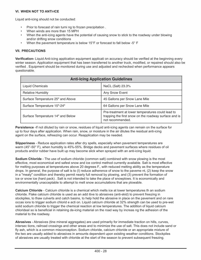
400 - 28
VI. WHEN NOT TO ANTI-ICE
Liquid anti-icing should not be conducted:
• Prior to forecast of rain turni ng to frozen precipitation .• When winds are more than 15 MPH• When the anti-icing agents have the potential of causing snow to stick to the roadway under blowing
and/or drifting snow conditions• When the pavement temperature is below 15°F or forecast to fall below -5° F
VII. PRECAUTIONS
Verification- Liquid Anti-icing application equipment applicati on accuracy should be verified at the beginning everywinter season. Application equipment that has been transferred to another truck, modified, or repaired should also beverified . Equipment should be monitored during use and adjusted and rechecked when performance appears questionable.
Anti-Icing Application GuidelinesLiquid Chemicals NaCL (Salt) 23.3%
Relative Humidity Any Snow EventSurface Temperature 25º and Above 45 Gallons per Snow Lane Mile
Surface Temperature 15º-24º 64 Gallons per Snow Lane Mile
Surface Temperature 14º and BelowPre-treatment at lower temperatures could lead totrapping the first snow on the roadway surface and isnot recommended.
Persistence -If not diluted by rain or snow, residues of liquid anti-icing agents can remain on the surface forup to four days after application. When rain, snow, or moisture in the air dilutes the residual anti-icingagent on the surface, refreezing can occur. Reapplication may be needed.
Slipperiness - Reduce application rates after dry spells, especially when pavement temperatures arewarm (45°-50° F), when humidity is 45%-55%. Bridge decks and pavement surfaces where residues of oilproducts and/or rubber have built up may become slick when sprayed with an anti-icing liquid.
Sodium Chloride - The use of sodium chloride (common salt) combined with snow plowing is the mosteffective, most economical and safest snow and ice control method currently available. Salt is most effectivefor melting purposes at temperatures above 20 degrees F., with reduced melting ability as the temperaturedrops. In generaI, the purpose of salt is to (I) reduce adherence of snow to the paveme nt, (2) keep the snowin a "mealy" condition and thereby permit nearly full removal by plowing, and (3) prevent the formation ofice or snow ice (hard pack) . Salt is not intended to take the place of snowplows. It is economically andenvironmentally unacceptable to attempt to melt snow accumulations that are plowable.
Calcium Chloride - Calcium chloride is a chemical which melts ice at lower temperatures th an sodiumchloride. Flake calcium chloride is used as an add itive to abrasives (anti-skid) to prevent freezing instockpiles, to thaw culverts and catch basins, to help hold the abrasive in place on the pavement and on rareoccas ions to trigger sodium chlorid e acti on. Liquid calcium chloride at 32% strength can be used to pre-wetsolid sodium chloride to trigger the chemical reaction at low temperatures. The addition of liquid calciumchlorideaI so is beneficial in retaining de-icing material on the road way by increas ng the adhesion of thematerial to the roadway.
Abrasives - Abrasives (tine mineral aggregates) are used primarily for immediate traction on hills, curves,intersec tions, railroad crossings and other areas and to minimize the use of salt. This does not include sand orfly ash, which is a common misconception. Sodium chloride, calcium chloride or an appropriate mixture ofthe two are usually added to abrasives in amounts dependent upon existing weather conditions. Stockpilesof abrasives are usually treated with chloride at the start of the season to prevent subsequent freezing.
400 - 29
VIII. APPLICATION OF DE-ICING MATERIALS
The use of chemicals, abrasives or chemical- abrasive mixtures is dependent not only on presentroadway and weather conditions, but also on anticipated changes in these conditions and fiscal or logisticconstraints experienced by PennDOT. The effects of peak traffic periods, approaching nightfall or daybreak,precipitation type, and predicted end of storm, are considered and evaluated prior to selecting the propermaterials and rate of application.
Adverse roadway conditions existing during periods o f low temperatures, which are predicted to rise,would generally be treated in accordance with the recommendations for the higher temperature. If the timeof day, trend and weather forecast is such that a drop in temperature may reasonably be expected ,treatment wouId generally be in accordance with the recommendation for the lower temperature.
Chemicals or abrasives should not be used at low temperatures if the pavement is dry and snow is blowingoff the pavement as su ch use would be wasteful and may be counterproductive.
Note: Chemical deicing materials are not recommended for Dirt & Gravel Roads.
IX. RATES OF APPLICATION
Generally , Sodium Chloride is the chemica of choice or most storm situations. Sodium chloride is usedto prevent snow pack and ice build-up on the pavement and to aid removal o f any build-up that occurs.Instructional guide lines are recommended to adequately maintain highways under most conditions and canbe found in Appendix H.
Chemicals or mixes are normally applied to the middle V3 of pavement width and on the high side of bankedcures. Spread width may be increased or decreased depending on the action of traffic. Materials are appliedearly in the storm so that brine develops on the pavement and prevents build -up of packed snow. It takesmuch less deicing chemical to remove compacted snow when the treatment is placed between thepavement/snow layer than if it is placed on top of the snow. If snow continues and accumulates on thepave ment, plowing should continue and additional chemical or mix-treatments should be made ifcompaction develops.
There are many additional circumstances which will necessitate modification to these treatments. Some of thesecircumstances are:
1. Rising or falling temperatures.2. When pavement is cold and dry and snowis falling. chemicals are not applied. Plowing and treatment of
icy spots, if they develop, is recommended.3. An abrasive chemical mix may be needed at extremely low temperatures or on very lightly traveled
highways. Under these conditions the effectiveness of salt is reduced and abrasives may be neededfor traction.
APPENDIX C -ANTI-ICING DECISION TREE
ANTI-ICING DECISION TREE DIRECTIONS
• Use this decision tree once per day and/or whenever the current weather forecast is significantly updated.• If the decision tree recommends against anti-icing but conditions have changed, reevaluate the decision
based on the new situation.• If there is a winter storm forecast for sleet, snow, freezing rain or frost that will adversely affect driving
conditions, it is desirable to have some form of salt residue on the road.• If there is no or very little salt residue on the road surface, anti-icing is recommended, except under the
following conditions.• If the event is forecasted to start as rain.• If the road surface temperature is below 15°F.• Some judgment is required to decide if the storm event will be sufficient to cause driving problems. However,
you should always err on the side of anti-icing, as it is a very cost effective treatment.

400 - 30
GENERAL PRINCIPLES OF ANTI-ICING
• Anti-icing can commence at least 48 hours in advance of the forecasted start time of a winter storm where practical. Bituminous pavements should be anti-iced first, then Portland Cement Concrete pavements. Higher priority routes should be anti-iced last as this reduces the potential for "dust-off.
• Once the decision to anti-ice has been made, the (45 gai/SLM minimum) rate may need to be increased to double the normal value to compensate for circumstances that would otherwise deplete the salt residue below value likely to be effective. These circumstances include applying salt brine more than 24 hours before theanticipated event, roads that have surfaces on which normal anti-icing rates have been observed to beineffective and sleet and/or freezing rain are anticipated.
• One key to a successful anti-icing program is to have quality salt brine as close to 23.3% solution as possible.Another key is to calibrate the anti-icing equipment at the beginning of and several times during the winter season.
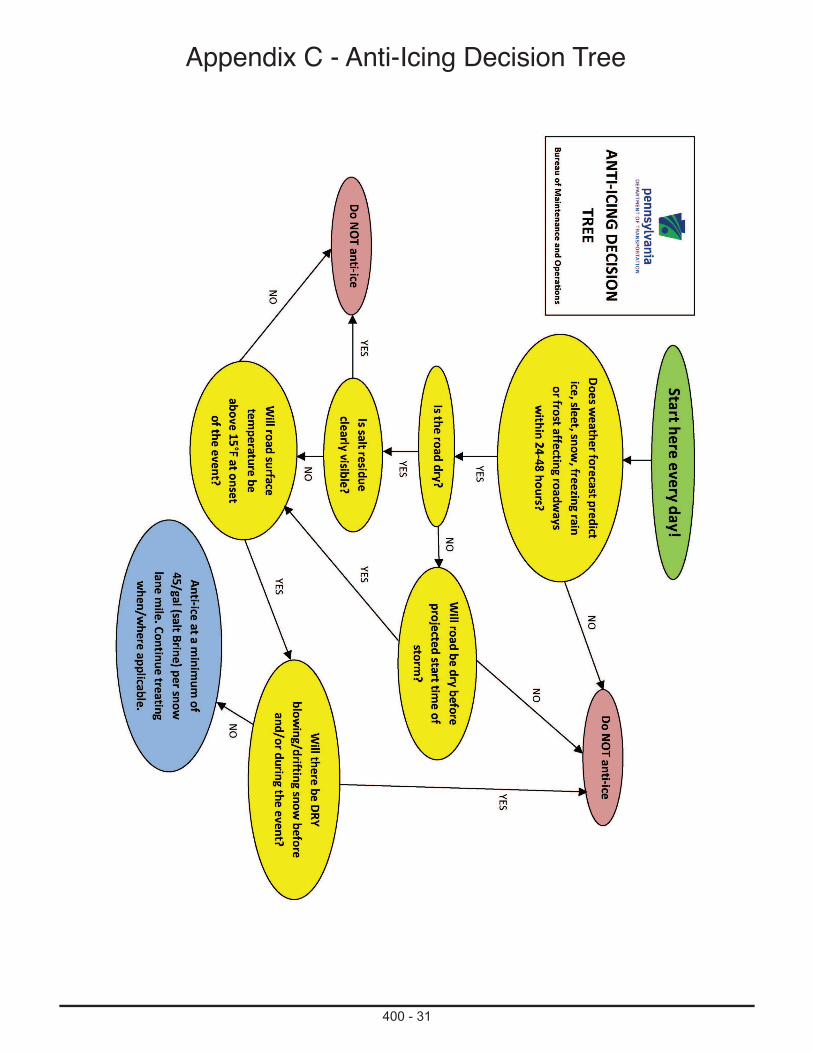
400 - 31
Appendix C - Anti-Icing Decision Tree

Section 500 Traffic Accommodation and Control
500 - 1
MS-0510-0005Sign Post Reflective Panels
I. DESCRIPTION — This work is the furnishing and installation of reflective sign post panels of the type indicated on either existing posts or posts installed for other purposes.
II. MATERIAL — As shown on the standard drawing or manufacture’s specification and as follows:
A. Panels. Provide materials from an approved manufacturer. Certify materials as specified in Publication 408, Section 106.03(b)3. Furnish cutout retroreflective sheeting material of the color indicated and at a minimum 2 inch in width and a maximum of 2 inch wider than post width being used.
B. Aluminum bolts nuts, lock-washers; brackets and bars (supports); lag screws; anti-theft sign hardware; banding-Publication 408, Section 1103.11.
III. CONSTRUCTION —
A. Attach panels permanently to supports as shown on the standard drawing or manufacturer’s specification. Mount the panel in a level position, correctly aligned, and firmly attached with anti-theft hardware.
B. Install panel for the full length of the support from the sign to within 2 feet above the edge of the roadway. Its color shall match the background color of the sign, except that the color of the strip for the YIELDand DO NOT ENTER signs shall be red. Use red on the reverse side of any post where a road user traveling in the wrong direction on that particular ramp or roadway would view it. Panels shall consist of retroreflector units that are capable of clearly retroreflecting light under normal atmospheric conditions from a distance of 1,000 feet when illuminated by the high beams of standard automobile lights.
IV. MEASUREMENT AND PAYMENT — Square Yard of panel. The unit price includes removal of existing panel(s), as necessary.
500 - 2
MS-0520-0022Patterned Thermoplastic Crosswalks
I. DESCRIPTION — This work is the preparation of the asphalt pavement surface area, supplying and placing an in-laid pre-cut thermoplastic pavement marking Decorative Crosswalk System, material, color and pattern as shown on the plans. The thermoplastic material is provided in sheets that are die-cut to match a prescribed pattern, thereby minimizing joints in the final product. Prepare the asphalt pavement to receive the thermoplastic sheet. Provide a template matching the pattern of the thermoplastic used to imprint depressions into the pavement.
II. MATERIAL—
A. Certification. MS-447A
1. Where directed, replace material that has not remained within reasonably close conformity to location or has not remained effective in performing useful service for a period of 180 days from the date of acceptance. The service is as follows:
• 90% of material remains in each crosswalk.
B. Inlaid Thermoplastic Material.
1. AASHTO T 250-05; Impact Resistance: Determine the impact resistance using the Izod-type impact apparatus as outlined generally in ASTM D 256, Method A. Do not use a notched specimen. Minimum impact resistance ≥ 11 in.-lb.
2. ASTM D523; Sheen ≥ 1 at 85°
3. ASTM D412; Tensile Strength ≥ 400 psi, but can be waived if ASTM D4541 values exceed 400 psi
4. ASTM D4060; Abrasion Resistance: Maximum loss 100 mg/1000 cycles, based on net loss between 500 to 1000 cycles.
5. ASTM D4541; Adhesion to Asphalt ≥ 180 psi
6. Meet Manufacturers Specifications
III. CONSTRUCTION —
A. Weather restrictions.
1. Do not install during periods of precipitation
2. Do not place system when air or surface temperature is 40º F or lower
B. Pattern and Color Limitations.
1. Refer to Publication 111M, TC-8600 Series Standard Drawing for approved colors and patterns.
C. Surface Preparation.
1. Place only within the planned designated areas.
2. Apply system to only asphalt surfaces that show no excessive oxidation. The existing pavement shall be stable, well compacted and in excellent condition. Repair of ruts, raveling, cracks, visible seams, and shallow points, is required before acceptance of the pavement surface by the installer.
3. Clean the surface of all loose particles, dirt, grease, and any other substance that may reduce the system’s ability to adhere to the existing surfaces.
D. Placement
1. Preheat road surface to between 235ºF to 326ºF utilizing an indirect heating mechanism that allows surface temperature monitoring at all times, gradually heat-saturate the mat without causing damage. Use of open flame and constant heat exposure is not allowed.

500 - 3
2. Heat soak (soften) the road surface to a minimum depth of 1/2 inch
3. Do not place materials if the mat temperature has exceeded 326ºF
4. Utilize templates and vibratory tampers to imprint the pattern to a depth of no less than 1/8 inch
5. Place the Pre-Formed/Pre-Cut Thermoplastic Material in accordance to plan and with the manufactures recommendations
6. Utilize vibratory plate compactors to press the templates into the heated asphalt surface
7. Border the decorative crosswalk by installing two white parallel lines (minimum 6 inches thick) with a PennDOT approved pavement marking material that extends from face of curb to face of curb or edge of shoulder
IV. MEASUREMENT AND PAYMENT — Square Yard
500 - 4
MS-0530-0024Patterned/Textured Crosswalk
I. DESCRIPTION — This work is the preparation of the area, supplying and placing a modified polyurethane resin-aggregate mixture as surface dressing, finishing and texturing the system in order to construct decorative crosswalks with the specified color, material, and texture pattern shown on the plans.
II. MATERIAL—
A. Certification. MS-447A
1. Where directed, replace material that has not remained within reasonably close conformity to location or has not remained effective in performing useful service for a period of 180 days from the date of acceptance. The service is as follows:
• 90% of material remains in each crosswalk.
B. Decorative modified polyurethane resin crosswalk.
1. AASHTO T 250-05; Impact Resistance: Determine the impact resistance using the Izod-type impact apparatus as outlined generally in ASTM D256-10, Method A. Do not use a notched specimen. Minimum impact resistance ≥ 25 in.-lb.
2. ASTM D523-08; Sheen ≥ 1 at 85°
3. ASTM D412-06a; Tensile Strength ≥ 400 psi, but can be waived if ASTM D4541 values exceed 400 psi.
4. ASTM D4060-10; Abrasion Resistance Maximum loss 100 mg/1000 cycles, based on net loss between 500 to 1000 cycles.
5. ASTM D4541-9a; Adhesion to Asphalt ≥ 180 psi
6. Meet Manufactures Specifications
Furnish a material with a minimum initial skid resistance of 50 British Pendulum Number (BPN) for all crosswalks, stop lines, or where indicated.
C. Aggregates. ASTM C295/C295M-12, Meet manufacturer’s specifications
D. Resin-based synthetic asphalt compound. ASTM D-4690-99, Meet manufacturer’s specifications
E. Reinforcement fibers. Meet manufacturer’s specifications
III. CONSTRUCTION —-
A. Weather restrictions.
1. Do not place system when precipitation is expected within 24 hours.
2. Do not place system when air or surface temperature is 10°C (50°F) or lower.
B. Pattern and Color Limitations.
1. Refer to Publication 111M, TC-8600 Series Standard Drawing for approved colors and patterns.
500 - 5
C. Surface Preparation.
1. Place only within the plan designated areas.
2. Apply system to only asphalt or concrete surfaces.
3. Apply system to only asphalt surfaces that show no excessive oxidation. The existing pavement shall be stable, well compacted and in excellent condition. Repair of ruts, raveling, cracks, visible seams, and shallow points, is required before acceptance of the pavement surface by the installer.
4. Mill all applicable leading edges to a consistent vertical depth 3/4 inch below the existing grade.
5. Clean the surface of all loose particles, dirt, grease, and any other substance that may reduce the system’s ability to adhere to the existing surfaces.
6. Seal concrete surfaces with a material meeting manufacturer’s specifications prior to placement of surface treatment.
D. Placement.
1. Mixture proportions are proprietary but must account for color and traffic use.
2. Thoroughly mix part ‘A’ (Resin) with part ‘B’ (Hardener) utilizing a suitable heavy duty electric paddle mixer or similar in amounts recommended by manufacturer.
3. Pre-wash and completely dry all aggregates and provide bagged materials consistent with the mixture proportions before batching and mixing.
4. Thoroughly mix aggregates and polyurethane binder mixture in the amounts recommended by manufacturer.
5. Apply, uniformly spread and finish surface between the grade control forms utilizing rubber squeegees and trowels as recommended by the manufacturer and as shown on the plans.
6. Imprint using an approved mold capable of providing a 3/8 inch to 1/2 inch deep imprint with the design details shown on the plans.
7. Use a manufacturer approved release agent to prevent imprinted material from sticking to the mold.
8. Provide a final texture and pattern shown on the plans.
9. Border the decorative crosswalk by installing two white parallel lines (minimum 6 inches thick) with a PennDOT approved pavement marking material that extends from face of curb to face of curb or edge of shoulder .
10. Remove all loose sand and clean entire surface area after Imprinting.
11. Do not allow vehicular traffic or loads on the system for a minimum of two hours from application or until the mixture is tack free.
IV. MEASUREMENT AND PAYMENT — Square Yard
500 - 6
MS-0540-0035Thermoplastic Manhole Protection Rings
I. DESCRIPTION — This work is the installation of manhole protection rings to provide a smooth graded transition of exposed manhole risers and collars to the pavement surface.
II. MATERIAL —
A. Certification. MS-447A
B. Thermoplastic.
1. Publication 408, Section 965. This is a non-reflective, non beaded product; disregard sections related to glass beads. Disregard requirements for temperature and wind speed.
III. CONSTRUCTION —
A. Preparing Existing Surface. Remove and dispose of all unsuitable material. Where necessary use a broom.
B. Installation:
1. Asphalt Pavements: Apply according to manufacturer recommendations. Apply at ambient and pavement temperatures above 32°F without any preheating of the pavement.
2. Portland Concrete Pavements: Section III,(b)1. Except as follows: Apply a manufacturer recommended concrete sealer before installing thermoplastic rings.
IV. MEASUREMENT AND PAYMENT —
A. Thermoplastic Manhole Protection Rings. Each
B. Concrete Sealer. Tube, or Gallon