Embed Size (px)
Citation preview

This Product Contains Trade Secrets, Proprietary & Confidential Information. Copying, Use or Disclosure Without Express Written Consent is Prohibited. © 2008 Valquest Systems, Inc .,
All Rights Reserved.
Z-Cap
Zero Voltage Closing Control
For Eaton/Cooper ECS ZVC Switches
Switched Capacitor Banks
Valquest Systems, Inc.

This Product Contains Trade Secrets, Proprietary & Confidential Information. Copying, Use or Disclosure Without Express Written Consent is Prohibited. © 2008 Valquest Systems, Inc .,
All Rights Reserved 2
Table of Contents Functional Description 3 Zero Voltage Closing Constant Close Operation Voltage Capacitor Temperature Compensation Switch Temperature Compensation Automated Close Time Calibration 4 Calibration Data Storage Automatic Close Timing Adjustment Switch Status Indication RS-232 Communications Control Panel 5 Switch Settings Open / Close Switch LED Indications Installation 6 Capacitor Switches AC Power Control Schemes Trip Command Close Command Switch Status Ready Status Capacitor Bank Configurations 7 Single phase Three phase grounded Wye Three phase un-grounded Wye Three phase delta Z-Cap Configuration 8 Modifying Closing Connections Determining Phase Rotation Switch Calibration 10 Laptop Calibration Front Panel Calibration Figures Figure 1. Front Panel 11 Figure 2. Switch Connector 12 Figure 3. Interface Terminal Block 12 Figure 4. Pole Wiring Diagram 13 Figure 5. Closing Connections 14 Figure 6. Typical Control Schemes 15 Figure 7. ZVC Switch Connections 16 Figure 8. Z-Cap with Standard Capacitor Control 17

This Product Contains Trade Secrets, Proprietary & Confidential Information. Copying, Use or Disclosure Without Express Written Consent is Prohibited. © 2008 Valquest Systems, Inc .,
All Rights Reserved 3
Z-Cap - Zero Voltage Closing Control Valquest Systems, Inc. This information herein is sensitive and proprietary to Valquest Systems, Inc.
Functional Description � Zero Voltage Closing
The Z-Cap accepts Close and Trip commands in the form of 120 VAC signals from any external control device such as a PLC or standard capacitor control. Input signals are opto-coupled to insure reliability of the system. The Z-Cap provides a wetting voltage which the controlling device can use if necessary. When a Close command is received the Z-Cap initiates a separate close operation for each phase. These operations are timed so that each switch’s main contacts make initial contact as close to zero crossing as possible. Zero crossing is defined as the time (two per cycle) when the phase conductor is at neutral potential (phase to neutral PT) or when the two phase conductors are at precisely the same potential (phase to phase PT).
� Constant Close Operation Control Voltage In order to close the entire bank in a timely manner, each capacitor switch is provided with its own stored energy circuit. These circuits include charged capacitors. The voltage on these capacitors is maintained to within 0.1 volts and is monitored constantly. As long as the capacitor voltage is within tolerance, the “READY” LED will be lit, indicating that the capacitors are charged and ready for operation. A set of dry contacts will also be closed to indicate this condition to the external control unit. The Close sequence cannot be initiated while the capacitor voltages are out of tolerance.
� Capacitor Temperature Compensation Because energy storage in a capacitor changes slightly with temperature, close timings change slightly with internal capacitor temperature. The Z-Cap microprocessor constantly monitors the temperature inside the enclosure and adjusts the Close Sequence timings for each phase based on stored energy curves. Time integration is used to allow for the lag between board temperature and internal capacitor temperature.
� Switch Temperature Compensation The primary temperature variable which affects Close timing accuracy is the capacitor switch solenoid temperature. The Z-Cap incorporates an exclusive proprietary technique for precisely monitoring this temperature and adjusting the Close Sequence timing accordingly. Valquest Systems is in the process of applying for patents to protect the use this concept and technique.

This Product Contains Trade Secrets, Proprietary & Confidential Information. Copying, Use or Disclosure Without Express Written Consent is Prohibited. © 2008 Valquest Systems, Inc .,
All Rights Reserved 4
Automated Close Time Calibration Before the control is ready for normal operation each switch circuit must be calibrated. Calibration can be done using switches on the front panel or with a laptop computer. Using a laptop is preferable because it is automatic and allows archiving of calibration data. For each phase, the user connects the calibration cables to the switch terminal (without high voltage applied ) and sets the front panel switches to the proper position (see Table 1: Switch Settings). He then starts the calibration sequence using the Z-Cap companion software. The laptop will take each switch through three complete operations during which the precise timings are monitored and stored in the Z-Cap non-volatile memory. This sequencing can also be done from the front panel.
� Calibration Data Storage
During calibration the timing parameters for each switch (including reference temperatures) are stored both in non-volatile memory in the Z-Cap. During power losses the Z-Cap will retain these settings.
� Automatic Close Timing Adjustment During every close sequence the Z-Cap uses an exclusive proprietary technique to monitor the motion of each switch solenoid. In conjunction with the calibration data this gives the microprocessor precise information with which to make slight adjustments to the stored timing parameters. This means that over long periods of time the zero voltage closing accuracy will be maintained. Valquest Systems is in the process of applying for patents to protect the use this concept and technique.
� Switch Status Indication
The trip circuit is continuously monitored to determine if the capacitor switches are closed or open. This is done without using any auxiliary switches and gives an absolute indication at the “STATUS” LED on the front panel of the bank status. A set of dry contacts also indicates this status to the external control unit.
� RS-232 Communications The control incorporates a 9 pin D type connector to communicate via RS-232 to a laptop with the Z-Cap companion software installed. This software allows the following functions: � Automated Calibration � Switch Testing � Data retrieval � Digital Close / Trip / Status (optional)

This Product Contains Trade Secrets, Proprietary & Confidential Information. Copying, Use or Disclosure Without Express Written Consent is Prohibited. © 2008 Valquest Systems, Inc .,
All Rights Reserved 5
Control Panel Refer to Figure 1. Switch Settings Description Rotation CPT Cal SW-1 SW-2 SW-3 Calibrate Switch 1 Down Up Down Down Calibrate Switch 2 Down Down Up Down Calibrate Switch 3 Down Down Down Up Single Phase N/A 1-N Up Up Down Down 3 Phase Grounded Wye 1-2-3 1-N Up Down Up Down 3 Phase Grounded Wye 3-2-1 1-N Up Down Down Up 3 Phase Grounded Wye 1-2-3 1-2 Up Up Up Down 3 Phase Grounded Wye 3-2-1 1-2 Up Up Down Up 3 Phase Ungrounded Wye N/A 3-N Up Down Up Up 3 Phase Ungrounded Wye N/A 1-2 Up Up Up Up 3 Phase Delta N/A 3-N Up Down Up Up 3 Phase Delta N/A 1-2 Up Up Up Up Table 1 Open / Close Switch The “Open / Close” momentary toggle switch is used during calibration if a laptop is not available. It can also be used for testing purposes. Both this switch and the “Cal” switch are only operational when the calibration cables are connected to the control unit. A jumper in the connector enables them. This insures that the switches will not be accidentally operated under normal conditions. LED Indications Description READY SW-1 SW-2 SW-3 STATUS Capacitor Voltages OK On Calibration Needed Switch 1 On Calibration Needed Switch 2 On Calibration Needed Switch 3 On Switches Closed On Table 2 In the normal operation mode only the “READY” LED should be lit as an indication that the control is ready to have the closing sequence initiated. The “STATUS” LED will be lit any of the capacitor switches is in the closed position. Two sets of dry contacts are available to send these two bits of information to the controlling device.

This Product Contains Trade Secrets, Proprietary & Confidential Information. Copying, Use or Disclosure Without Express Written Consent is Prohibited. © 2008 Valquest Systems, Inc .,
All Rights Reserved 6
Installation � Capacitor Switches
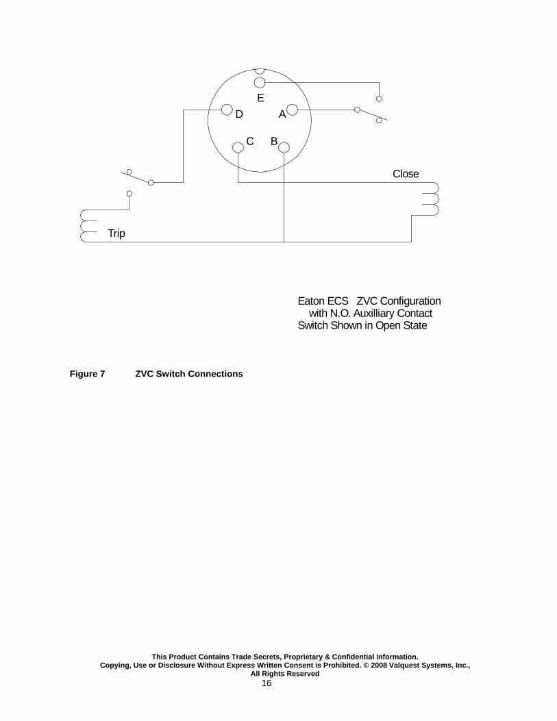
The capacitor switches must be solenoid operated Eaton ECS switches configured for ZVC operation. This means they must be internally wired such that the trip solenoid has a standard micro-switch installed that interrupts the trip signal after the main contacts have opened. The close solenoid must be wired directly to the connector with no interposing micro-switch. See Figure 8 for standard pin connections.
� AC Power The Z-Cap works on 120VAC 60 Hz. This voltage is normally supplied from a control transformer. It enters through the seven pin Amphenol connector located on the bottom of the unit (see Figure 2: Power Connector). This transformer provides the power for charging the closing capacitors, the power for tripping the main switches and a reference voltage for calculating the voltage zero cross timing. In order for the control to operate properly, the primary of this transformer must be wired between neutral and the same phase as the switch that is controlled by the SW-1 closing circuit in the Z-Cap or between the two phases which correspond to the switches being controlled by the SW-1 and SW-2 closing circuits in the Z-Cap (see Table 1: Switch Settings).
� Control Schemes There are many command schemes possible. Figure 6 shows two common schemes, one for a PLC and one for an Automatic Capacitor Control being powered from the Z-Cap. Figure 7 shows basic configuration for a Capacitor Control Meter Base and Z-Cap on the same structure.
� Trip Command
The Trip command is received as a 120 VAC signal on pins B and C of the Control Connector or a dry contact to pins A and B of the Control Connector (see Figure 3: Terminal Block Connections). The signal should last 300 milliseconds and no longer than 2 seconds.
� Close Command The Close command is received as a 120 VAC signal on pins D and C of the Control Connector or a dry contact to pins A and D of the Control Connector (see Figure 3: Control Connections). The signal should last 600 milliseconds and no longer than 2 seconds.
• Status
Switch Status can be read as a dry contact on pins E and F of the Control Connector (see Figure 3: Control Connections). The dry contact will be closed if any of the capacitor switches are closed. The contact will be open if all of the connected capacitor switches are open.
• Ready Ready Status can be read as a dry contact on pins G and F of the Terminal Block (see Figure 3: Control Connections). A closed contact indicates that the closing circuit capacitors are charged and the Z-Cap is ready close the switches.

This Product Contains Trade Secrets, Proprietary & Confidential Information. Copying, Use or Disclosure Without Express Written Consent is Prohibited. © 2008 Valquest Systems, Inc .,
All Rights Reserved 7
Capacitor Bank Configurations Different cap bank configurations each call for a different set of timing parameters to be stored for zero voltage closing. The configurations can be defined with three characteristics:
A. Phase rotation (1-2-3 or 3-2-1) B. Grounded Wye, un-grounded Wye or delta C. Phase relation of the voltage reference (CPT connected phase-neutral or phase-phase) • A delta configuration is handled identically to an un-grounded Wye. • The rotation does not need to be known when the configuration is delta or un-grounded Wye. • The Z-Cap will always close the switches in order of 1 first, then 2, then 3. • In the configurations below the CPT must be connected to the phase(s) connected to the
indicated switches. • Z-Cap switch connection modifications can be made in the enclosure if necessary.
Standard Capacitor Bank Configurations: � Single phase
The control will operate only the switch 1 closing circuit
� Three phase grounded Wye – 1-2-3 rotation with CPT on 1-N Closes switch 1 at the zero crossing of the reference voltage Closes switch 2 at the zero crossing of the reference voltage plus 120 degrees Closes switch 3 at the zero crossing of the reference voltage plus 60 degrees
� Three phase grounded Wye – 3-2-1 rotation with C PT on 1-N
Closes switch 1 at the zero crossing of the reference voltage Closes switch 2 at the zero crossing of the reference voltage plus 60 degrees Closes switch 3 at the zero crossing of the reference voltage plus 120 degrees
� Three phase grounded Wye – 1-2-3 rotation with CPT on 1-2 Closes switch 1 at the zero crossing of the reference voltage plus 30 degrees Closes switch 2 at the zero crossing of the reference voltage minus 30 degrees Closes switch 3 at the zero crossing of the reference voltage plus 90 degrees
� Three phase grounded Wye – 3-2-1 rotation with C PT on 1-2 Closes switch 1 at the zero crossing of the reference voltage minus 30 degrees Closes switch 2 at the zero crossing of the reference voltage plus 30 degrees Closes switch 3 at the zero crossing of the reference voltage plus 90 degrees
� Three phase un-grounded Wye or Delta with CPT on 3 -N Closes switch 1 at the zero crossing of the reference voltage Closes switch 2 at the zero crossing of the reference voltage plus 90 degrees Closes switch 3 at the zero crossing of the reference voltage
� Three phase un-grounded Wye or Delta with CPT on 1 -2
Closes switch 1 at the zero crossing of the reference voltage Closes switch 2 at the zero crossing of the reference voltage Closes switch 3 at the zero crossing of the reference voltage plus 90 degrees
Please refer to Page 5 Table 1: “Switch Settings” for programming the control.

This Product Contains Trade Secrets, Proprietary & Confidential Information. Copying, Use or Disclosure Without Express Written Consent is Prohibited. © 2008 Valquest Systems, Inc .,
All Rights Reserved 8
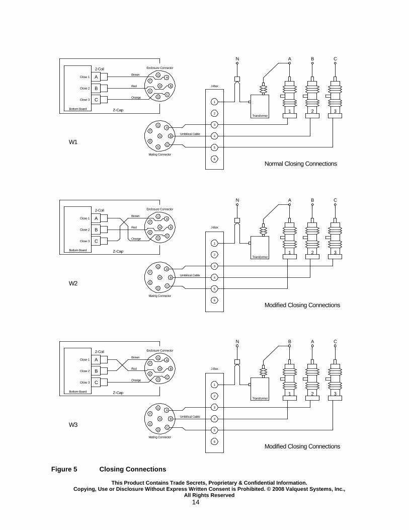
Z-Cap Configuration
Modifying Closing Connections
Sometimes capacitor switch wiring is not aligned properly with the transformer for the bank configuration.
• Inside the Z-Cap enclosure, under the access panel, are switch swapping jacks. • They are labeled A, B and C. • Because the switch closing order is always 1-2-3, the switches must be connected in positions
relative to the transformer as shown in Table 1. • When the switches are improperly connected, these swapping jacks provide an easy way to set
the wiring right. • Figure 5 shows the Normal (factory wired) setup and 2 examples of modified setups. • The pictures here show the swapping jacks and how they are connected from the factory.
• Figure 5-W1 shows the normal (factory wired) connections. • Figure 5-W2 shows a situation where the bank has been wired so that the #3 closing circuit is
connected to the phase that the transformer is on. The Brown and Orange wire have been swapped in the Z-Cap to correct it.
• Figure 5-W3 shows a situation where the bank has been wired so that the #2 closing circuit is connected to the phase that the transformer is on. The Brown and Red wires have been swapped in the Z-Cap to correct it.
• These corrections are done completely irrespective of the utility’s phase references. A B and C have no meaning to the Z-Cap except as it affects phase rotation.
Circular Connector Jacks ECS switches use the 2-Coil group
Normal Connections A-Brown, B Red, C-Orange

This Product Contains Trade Secrets, Proprietary & Confidential Information. Copying, Use or Disclosure Without Express Written Consent is Prohibited. © 2008 Valquest Systems, Inc .,
All Rights Reserved 9
Determining Phase Rotation
Phase Rotation is called ABC if B peaks after A and C peaks after B. The opposite is called CBA.
In the case of the Z-Cap it is called 1-2-3 (like the picture). The opposite rotation is 3-2-1. Z-Cap terminology does not use A, B and C to avoid confusion with the utilities’ names for the phases. When the capacitor bank configuration is Grounded Wye, the phase rotation must be known. Assuming that the utility personnel know the phase rotation and can identify the phases, the rotation as it relates to the Z-Cap can be determined. For instance if Z-Cap circuits are as follows:
• SW-1 connected to Phase A • SW-2 connected to Phase B • SW-3 connected to Phase C • Utility rotation is ABC
Z-Cap rotation is 1-2-3. This is the case shown in Figure 5-W1. Figure 5-W2 has this same scenario after swapping the brown and orange wires in the Z-Cap. So once again if utility rotation is ABC the Z-Cap rotation is 1-2-3. Of course if utility rotation is CBA then Z-Cap rotation is 3-2-1. In Figure 5-W3 the phases are not 1 to A, 2 to B, and 3 to C. If utility rotation is ABC then Z-Cap rotation is 2-1-3 which is effectively 3-2-1. If utility rotation is CBA the Z-Cap rotation is 1-2-3. Many times utility personnel will not know the rotation. Here are some possible methods for determining rotation.
• If a metering point is nearby and the overhead phases can be traced to the test switches in the cabinet it may be possible to use a phase rotation meter or power quality meter to determine the utility’s rotation.
• If a set of regulators exists on the line, a phase rotation meter can be used with them. This may require the use of some lengths of wire.
• At the substation: sometimes electronic recloser controls will have the phase rotation as part of their settings. This may require use of a laptop and possibly the manufacturer’s configuration software.
It is important to get the Z-Cap rotation right with Grounded Wye banks because otherwise the closing point will be far from zero. This is because the closing angles are 120° apart. So, for instance, if the phase connected to Switch 2 crosses 0 volts 120° af ter the phase on Switch 1 (rotation = 1-2-3) but Switch 2 closes at 240° after Switch 1, the voltage will be at 0.867 of crest rather than 0. With Un-Grounded Wye banks and Delta banks it is not necessary to know rotation. This is because there is no current when Switch 1 closes and Switches 2 and 3 close 90° apart. If the rotation is backwards it has the effect of making the requirement -90°. But 90° and -90° are 180° apart.

This Product Contains Trade Secrets, Proprietary & Confidential Information. Copying, Use or Disclosure Without Express Written Consent is Prohibited. © 2008 Valquest Systems, Inc .,
All Rights Reserved 10
Calibration The control must be calibrated for all three phases (except when operating as single phase) before it can accurately close the switches relative to the zero voltage points. It must also be set for the proper cap bank and voltage sense configuration. Please refer to Table 1: (Switch Settings) to determine how to set the front panel switches for calibration and normal operation. Laptop Field Calibration
1. Make sure that the terminals on all three main capacitor switches are not connected to anything. 2. Use the Close / Trip switch on the front panel to make sure all switches are in the open position. 3. Connect the Calibration Cables to the Z-Cap Serial Port (DB-9 connector). 4. Connect the two clips on the Calibration Cables to the two terminals of the switch being calibrated. 5. Connect the serial cable from the laptop to the Calibration Cable Connector and start the Z-Cap
Companion software. 6. Make sure that Cooper ECS switch type is selected. 7. Making sure the indicated serial port is correct, click the Connect button. 8. On the Calibration tab, select the switch to be calibrated. 9. Click the Calibrate button. The laptop will take the control through three complete operations. 10. Move the calibration clips to the next switch and repeat steps 8 and 9 for the other switches. 11. Set the front panel switches to the proper positions based on the bank configuration as detailed in
Table 1. Front Panel Field Calibration
1. Make sure that the terminals on all three main capacitor switches are not connected to anything. 2. Use the Close / Trip switch on the front panel to make sure all the capacitor switches are in the
open position. 3. Connect the Calibration Cables to the Z-Cap. 4. Connect the two clips on the Calibration Cables to the two terminals of the switch being calibrated. 5. Set front panel switch Cal to the up position. 6. Set front switch SW-1, SW-2 or SW-3 to the up position corresponding to the switch being
calibrated. 7. Set front panel switch Cal to the Down position. This causes the control to enter the calibration
mode for the capacitor switch indicated by the SW-1, SW-2 and SW-3 front panel switches. 8. Use the Close / Trip switch on the front panel to initiate a close operation. 9. Observe that the SW-1/Cal light is lit. If it is not lit, the Z-Cap did not get a good read on the switch
closure. Inspect the Calibrations Cable connection at the Z-Cap enclosure and at the cap switch. 10. Use the Close / Trip switch on the front panel to initiate a trip operation. 11. Repeat steps 8 and 9 twice more for a total of 3 complete operations. 12. Set front panel switch Cal to the up position. 13. Observe that the Light for the switch being calibrated is not lit. If it is lit, calibration was not done
correctly. Repeat steps 6 – 11. 14. Perform steps 4 – 12 for all three capacitor switches. 15. Set switches to the proper positions based on the bank configuration as detailed in Table 1.

This Product Contains Trade Secrets, Proprietary & Confidential Information. Copying, Use or Disclosure Without Express Written Consent is Prohibited. © 2008 Valquest Systems, Inc .,
All Rights Reserved 11
Figure 1 Front Panel

This Product Contains Trade Secrets, Proprietary & Confidential Information. Copying, Use or Disclosure Without Express Written Consent is Prohibited. © 2008 Valquest Systems, Inc .,
All Rights Reserved 12
Connections
GA
B
CD
E
F
H
Figure 2 Power Connector
Pin Signal A Close Switch 1 B Close Switch 2 C Close Switch 3 D Trip Switches (All) E Line Current F Wye Neutral Current G 120 VAC H Neutral
AH B
G K J C
F DE
Figure 3 Automatic Capacitor Control (ACC) Connecto r
Pin Signal Direction A 120 VAC ACC � Z-Cap B Trip Signal ACC � Z-Cap C Trip/Close Common ACC � Z-Cap D Close Signal ACC � Z-Cap E Switch Status ACC � Z-Cap F Status Common ACC � Z-Cap G Ready Status ACC � Z-Cap H Line Current ACC � Z-Cap J Wye Neutral Current ACC � Z-Cap K Neutral ACC � Z-Cap
Trip and Close commands require 120 VAC Signal for 350 +/- 50 msec. Switch and Ready Statuses are dry contacts.

This Product Contains Trade Secrets, Proprietary & Confidential Information. Copying, Use or Disclosure Without Express Written Consent is Prohibited. © 2008 Valquest Systems, Inc .,
All Rights Reserved 13
G
AmphenolConnectorfrom Z-Cap
1. Neutral2. 120VAC3. Close A4. Close B5. Close C6. Trip ABC7. Line Current8. Wye Neutral Current
Switches
Wiring for Z-Cap
1 2 3 4 5 6
Junction Box
TransformerLine
Neutral
Pole TopGround Level
A. N/CB. NeutralC. CloseD. TripE. N/C
B C D1 2 3
B C D B C D
GA
B
CD
E
F
H
N S
7 8
LPCS
Wye Neut CT(Optional)
(Optional)
Figure 4 Pole Wiring
This Product Contains Trade Secrets, Proprietary & Confidential Information. Copying, Use or Disclosure Without Express Written Consent is Prohibited. © 2008 Valquest Systems, Inc .,
All Rights Reserved 14
A
B
C
N A B C
1 2 3Transformer
J-Box
Umbilical Cable
Close 1
Close 2
Close 3
Enclosure Connector
Mating Connector
1
2
3
4
5
6
2-Coil
Bottom Board Z-Cap
Brown
Red
Orange
Normal Closing Connections
A
B
C
N A B C
1 2 3Transformer
J-Box
Close 1
Close 2
Close 3
Enclosure Connector
1
2
3
4
5
6
2-Coil
Bottom Board Z-Cap
Brown
Red
Orange
Modified Closing Connections
A
B
C
N B A C
1 2 3Transformer
J-Box
Close 1
Close 2
Close 3
Enclosure Connector
1
2
3
4
5
6
2-Coil
Bottom Board Z-Cap
Brown
Red
Orange
Modified Closing Connections
W2
W1
W3
GA
B
CD
E
F
H
GA
B
CD
E
F
H
GA
B
CD
E
F
H
Umbilical Cable
Mating Connector
GA
B
CD
E
F
H
GA
B
CD
E
F
H
Umbilical Cable
Mating Connector
GA
B
CD
E
F
H
Figure 5 Closing Connections

This Product Contains Trade Secrets, Proprietary & Confidential Information. Copying, Use or Disclosure Without Express Written Consent is Prohibited. © 2008 Valquest Systems, Inc .,
All Rights Reserved 15
A 120 VACB TripC Trip/Close CommonD CloseE Switch StatusF Status CommonG Ready StatusH Line CurrentJ Wye Neutral CurrentH Neutral
AH B
G K J C
F DE
120 VAC Power
LPCS Current Signal
Neutral
Trip Relay
Close Relay
Automatic Capacitor Control
AH B
G K J C
F DE
120 VAC
Z-Cap Ready Status
Neutral
Trip Relay
Close Relay
Substration PLC
24 VDC
Switch Status
Z-Cap
Z-Cap
Figure 6 Typical Control Schemes
This Product Contains Trade Secrets, Proprietary & Confidential Information. Copying, Use or Disclosure Without Express Written Consent is Prohibited. © 2008 Valquest Systems, Inc .,
All Rights Reserved 16
E
A
BC
D
Close
Trip
Eaton ECS ZVC Configuration with N.O. Auxilliary ContactSwitch Shown in Open State
Figure 7 ZVC Switch Connections

This Product Contains Trade Secrets, Proprietary & Confidential Information. Copying, Use or Disclosure Without Express Written Consent is Prohibited. © 2008 Valquest Systems, Inc .,
All Rights Reserved 17
Z-Cap
Socket forCap Control
J-Box
8 conductor #12
5 conductor #16
Cable Connectionsfor Z-Cap withStandard Control
See Cap Rack Wiring Drawing
Amphenol Connectors
Figure 8 Z-Cap with Standard Capacitor Control