Embed Size (px)
Citation preview

CNR Advisory Committee on Technical Recommendations for Construction
CNR-DT 203/2006
ROME CNR January 26th, 2006
GFRP systems
for diaphragm walls and piles
User Guide
U n d e r g r o u n d & C i v i l W o r k s d i v i s i o n

Index
2 Engineering and supplying - Specifications
3 Design
4 The Product
5 Physical/Mechanical Properties
6 Some official laboratory test report
7 Stirrups- technical note
8 Test method for strength of FRP bent bars and stirrups at bend
locations
9 Quality control certificates
10 Handling and Placement of the assembled cages
11 References projects and jobs
1 Definition of Soft-eyes - Diaphragm and large-diameter round piles
reinforced with GFRP bars

Introduction to Soft Eye
Composite materials (FRP, Fiber Reinforced Polymer) are today widely used in applications related
to structural engineering. Originally developed in aeronautic-aerospace environment, they found a
niche in the building material arena to be used as external strengthening of existing RC (Reinforced
Concrete) structures and as steel-replacement in new RC members. Their principal advantages are
high tensile strength, lightweight, and corrosion-free properties. For the latter reason FRPs are
mostly employed to replace steel reinforcement in harsh environment conditions.
One of the most used field application of FRP material is the replacement of steel reinforcing bars
in RC members for the realization of subways and underground wastewater treatment systems.
More in general, FRP is successfully used when RC members need to be drilled to allow the
creation of underground lines by means of TBMs (Tunnel Boring Machines).
The advantage of the combined used of FRP and TBM stems from the peculiar characteristic of FRP
bars to be extremely resistant in the fiber direction and extremely easy to cut in the orthogonal
direction. The term Soft-Eyes has been introduced to indicate those portion of the structures
reinforced with FRP bars where a TBM will pass through. Soft-Eyes expedite boring operations and
allow time and money saving during the realization of the line.
1
1 - Definition of Soft-eyes - Diaphragm and
large-diameter round piles reinforced
with GFRP bars

2- Engineering and supplying -
Specifications
Our services includes cooperation with engineering staff of the construction company for
dimensioning and full definition of the reinforcements.
The ATP team:
prepares a preliminary design to be discussed with the engineer-of-record.
ATP prepares the tender on the basis of the preliminary design.
In case of green light by the engineer-of-record and following the material order to
ATP will prepare the final document based on the comments suggested with the
engineer-of-record.
The final document will include the bill of material needed and the drawing of the
GFRP cages.
The specs:
ACI 440.1R-06
ACI 440.3R-04 Guide Test Methods for Fiber-Reinforced Polymers
CNR-DT 203/2006 Guide for the Design and Construction of Concrete
Structures Reinforced with Fiber-Reinforced Polymer Bars .
AASHTO LRFD Bridge Design Guide Specifications for GFRP-Reinforced
Concrete Bridge Decks and Traffic Railings, First Edition
https://bookstore.transportation.org).
Website links
www.concrete.org (ACI, American Concrete Institute).
www.cnr.it (CNR, Italian National Research Council).
2

CNR Commissione incaricata di formulare pareri in materia di normativa tecnica relativa alle costruzioni
NATIONAL RESEARCH COUNCIL
ADVISORY COMMITTEE
ON TECHNICAL RECOMMENDATIONS FOR CONSTRUCTION
Guide for the Design and Construction
of Concrete Structures Reinforced
with Fiber-Reinforced Polymer Bars
CNR-DT 203/2006
ROME CNR January 26th, 2006
3

CNR-DT 203/2006
INDICE
1 FOREWORD................................................................................................................................. 1
1.1 PUBLIC HEARING ................................................................................................................. 3
2 INTRODUCTION......................................................................................................................... 4
2.1 SYMBOLS ............................................................................................................................... 4
3 MATERIALS................................................................................................................................. 6
3.1 MANUFACTURING TECHNIQUES ..................................................................................... 6
3.2 CHARACTERISTICS OF FRP BARS .................................................................................... 6
3.2.1 Geometrical properties .......................................................................................................6
3.2.2 Strength and Young’s modulus of elasticity for tensile stress in the longitudinal
direction (bar axis)..............................................................................................................6
3.2.3 Coefficients of thermal expansion......................................................................................7
3.2.4 Static fatigue.......................................................................................................................8
3.2.5 Bar-concrete bond ..............................................................................................................8
3.3 FRP GRIDS CHARACTERISTICS......................................................................................... 8
3.4 TECHNICAL DATA SHEET FOR FRP BARS...................................................................... 8
3.5 CERTIFICATION AND FACTORY PRODUCTION CONTROL ........................................ 8
3.6 ACCEPTANCE ........................................................................................................................ 9
4 BASIS OF DESIGN .................................................................................................................... 10
4.1 BASIC REQUIREMENTS..................................................................................................... 10
4.2 STRUCTURE SERVICE LIFE.............................................................................................. 10
4.3 DURABILITY REQUIREMENTS ........................................................................................ 10
4.4 REINFORCEMENT: GENERAL PRINCIPLES................................................................... 11
4.4.1 Introduction ......................................................................................................................11
4.4.2 Design loads .....................................................................................................................11
4.4.3 Material properties............................................................................................................11
4.4.4 Design capacity ................................................................................................................12
4.5 PARTIAL FACTORS ............................................................................................................ 12
4.5.1 Material partial factors m.................................................................................................12
4.6 SPECIAL DESIGN PROBLEMS AND RELEVANT CONVERSION FACTORS............. 12
4.6.1 Environmental conversion factor a .................................................................................12
4.6.2 Loading modes and conversion factors for long-term effects l .....................................13
4.7 FLEXURE .............................................................................................................................. 14
4.7.1 Introduction ......................................................................................................................14
4.7.2 Analysis of the behaviour for ultimate limit state ............................................................14 4.7.2.1 Design basis ........................................................................................................................ 14
4.7.2.2 Member flexural capacity.................................................................................................... 14
4.7.2.3 Minimum reinforcement ..................................................................................................... 16
4.7.3 Service limit state analysis ...............................................................................................16 4.7.3.1 Design assumptions............................................................................................................. 16
4.7.3.2 Stress limitation................................................................................................................... 17
4.7.3.3 Deflection control................................................................................................................ 17
4.7.3.4 Crack control ....................................................................................................................... 18
4.8 SHEAR ................................................................................................................................... 20
4.8.1 Introduction ......................................................................................................................20
4.8.2 Basis for design ................................................................................................................20 4.8.2.1 Members without shear reinforcement................................................................................ 20
4

CNR-DT 203/2006
4.8.2.2 Elements with shear reinforcement ..................................................................................... 20
4.8.3 Minimum shear reinforcement .........................................................................................21
4.9 SECONDARY FRP REINFORCEMENT ............................................................................. 21
4.10DEVELOPMENT LENGTH.................................................................................................. 21
4.11CONSTRUCTION DETAILS................................................................................................ 22
5 APPENDIX A (MANUFACTURING TECHNIQUES OF FRP BARS AND GRIDS) ........ 24
5.1 FRP BARS.............................................................................................................................. 24
5.2 FRP GRIDS ............................................................................................................................ 26
6 APPENDIX B (TEST METHODS FOR CHARACTERISING FRP BARS) ....................... 27
6.1 METHOD FOR CALCULATING THE GEOMETRIC PROPERTIES ............................... 27
6.2 METHOD FOR CALCULATING THE MECHANICAL PROPERTIES ............................ 27
7 APPENDIX C .............................................................................................................................. 30
7.1 TECHNICAL DATA SHEET FOR FRP BARS.................................................................... 30
8 APPENDIX D .............................................................................................................................. 32
8.1 SELECTION AND TESTING OF FRP BARS: TASKS AND RESPONSIBILITIES
OF PROFESSIONALS........................................................................................................... 32
9 APPENDIX E (CALCULATING DEFLECTIONS AND CRACK WIDTHS FOR
FLEXURAL ELEMENTS OF CONCRETE REINFORCED WITH FRP BARS) ............. 34
10 ACKNOWLEDGEMENTS........................................................................................................ 35
5

CNR-DT 203/2006
3 MATERIALS
3.2 CHARACTERISTICS OF FRP BARS
(1)P The determination of both the geometrical as well as the mechanical properties of FRP bars
requires the use of specific procedures.
3.2.1 Geometrical properties
(1)P In relation to the considerable variety of bars available on the market, also in terms of cross
section geometry, it is worth referring to an equivalent (or nominal) circular cross section, with both
the diameter and area being defined properly.
(2) One of the procedures for the evaluation of equivalent diameter and area is described in
Appendix B.
6 APPENDIX B (TEST METHODS FOR CHARACTERISING FRP BARS)
This Appendix includes the test methods for determining the geometric and mechanical properties
of FRP bars, as proposed by the ACI Committee 440 in the document entitled “Guide Test Methods
for Fiber-Reinforced Polymers (FRPs) for Reinforcing or Strengthening Concrete Structures”
(2004).
6.1 METHOD FOR CALCULATING THE GEOMETRIC PROPERTIES
The following test method described is intended to determine the equivalent cross sectional area of
an FRP bar.
At least five bar specimens, approximately 200 mm long, shall be used. The specimens shall be
conditioned prior to test in accordance to procedure A of ASTM D 618 standard.
This procedure requires that the specimen bars with a diameter of approximately 7 mm or less are
conditioned for 40 hours at 23°C with 50% relative humidity whereas those bars with a diameter
greater than 7 mm shall be conditioned for 88 hours under the same conditions.
The tests shall be carried out under standard environmental conditions (at 23 3 °C and 50 10 %
relative humidity) with the specimens being kept in the test environment for at least 24 hours prior
to testing.
The tests consists of immersing the specimen bars in a graduated cylinder filled with either water,
or ethanol if air bubbles are present on the specimen surface, and then once the bars are fully
immersed, measuring the volume increase of the liquid.
The cylinder used shall be of an appropriate height in order to contain the whole bar as well as
ensure that there will be no overflow once the specimen is immersed. It shall also be graduated
with a maximum gradient of 10 ml.
In order to determine the equivalent cross sectional area of the tested specimen, Ap, its average
length, lp, shall be determined. The latter is assumed to be equal to the average value of the three
specimen lengths, measured rotating the bar by 120° for each measure. The measurement shall be
carried out using callipers with a precision of 0.025 mm.
Once the average length of the single specimen, lp, has been calculated, its equivalent cross
sectional area can be evaluated using the following expression:
1p
p
V VA
l
0 , (6.1)
where V0 and V1 are the volume in the cylinder before and after immersing the bar, respectively.
6

ACI 440.1R-06 supersedes ACI 440.1R-03 and became effective February 10, 2006.Copyright © 2006, American Concrete Institute.All rights reserved including rights of reproduction and use in any form or by any
means, including the making of copies by any photo process, or by electronic ormechanical device, printed, written, or oral, or recording for sound or visual reproductionor for use in any knowledge or retrieval system or device, unless permission in writingis obtained from the copyright proprietors.
440.1R-1
ACI Committee Reports, Guides, and Commentaries areintended for guidance in planning, designing, executing, andinspecting construction. This document is intended for the useof individuals who are competent to evaluate the significanceand limitations of its content and recommendations and whowill accept responsibility for the application of the material itcontains. The American Concrete Institute disclaims any andall responsibility for the stated principles. The Institute shallnot be liable for any loss or damage arising therefrom.
Reference to this document shall not be made in contractdocuments. If items found in this document are desired by theArchitect/Engineer to be a part of the contract documents, theyshall be restated in mandatory language for incorporation bythe Architect/Engineer.
Guide for the Design and Construction of
Structural Concrete Reinforced with FRP Bars
ACI 440.1R-06
Tarek Alkhrdaji Edward R. Fyfe James Korff Morris Schupack
Charles E. Bakis* T. Russell Gentry Michael W. Lee David W. Scott
P. N. Balaguru Janos Gergely John Levar Rajan Sen
Lawrence C. Bank William J. Gold Ibrahim M. Mahfouz Khaled A. Soudki
Abdeldjelil Belarbi Nabil F. Grace Orange S. Marshall Samuel A. Steere
Brahim Benmokrane Mark F. Green Amir Mirmiran Robert Steffen
Gregg J. Blaszak Zareh B. Gregorian Ayman S. Mosallam Gamil S. Tadros
Timothy E. Bradberry* Doug. D. Gremel Antonio Nanni*† Jay Thomas
Gordon L. Brown H.R. Trey Hamilton Kenneth Neale Houssam A. Toutanji
Vicki L. Brown Issam E. Harik John P. Newhook J. Gustavo Tumialan
T. Ivan Campbell Kent A. Harries Max L. Porter Milan Vatovec
Raafat El-Hacha Mark P. Henderson Mark Postma Stephanie L. Walkup
Garth J. Fallis Bohdan N. Horeczko Hayder A. Rasheed David White
Amir Z. Fam Vistasp M. Karbhari Sami H. Rizkalla
John P. BuselChair
Carol K. Shield*
Secretary
7

440.1R-2 ACI COMMITTEE REPORT
Chapter 5—Material requirements and testing,p. 440.1R-14
5.1—Strength and modulus grades of FRP bars
5.2—Surface geometry
5.3—Bar sizes
5.4—Bar identification
5.5—Straight bars
5.6—Bent bars
Chapter 6—Construction practices, p. 440.1R-166.1—Handling and storage of materials
6.2—Placement and assembly of materials
6.3—Quality control and inspection
Chapter 7—General design considerations,p. 440.1R-16
7.1—Design philosophy
7.2—Design material properties
Chapter 8—Flexure, p. 440.1R-188.1—General considerations
8.2—Flexural strength
8.3—Serviceability
8.4—Creep rupture and fatigue
Chapter 9—Shear, p. 440.1R-249.1—General considerations
9.2—Shear strength of FRP-reinforced members
9.3—Detailing of shear stirrups
9.4—Shear strength of FRP-reinforced two-way concrete
slabs
Chapter 10—Temperature and shrinkagereinforcement, p. 440.1R-27
Chapter 11—Development and splices ofreinforcement, p. 440.1R-28
11.1—Development of stress in straight bar
11.2—Development length of bent bar
11.3—Development of positive moment reinforcement
11.4—Tension lap splice
Chapter 12—References, p. 440.1R-3012.1—Referenced standards and reports
12.2—Cited references
Chapter 13—Beam design example, p. 440.1R-38
Appendix A—Slabs-on-ground, p. 440.1R-44A.1—Design of plain concrete slabs
A.2—Design of slabs with shrinkage and temperature
reinforcement
CHAPTER 1—INTRODUCTIONThis is the third revision of the design and construction
guide on fiber-reinforced polymer (FRP) reinforcement for
concrete structures. Many successful applications world-
wide using FRP composite reinforcing bars during the past
decade have demonstrated that it can be used successfully
and practically. The professional using this technology
should exercise judgment as to the appropriate application of
FRP reinforcement and be aware of its limitations as
discussed in this guide. Currently, areas where there is
limited knowledge of the performance of FRP reinforcement
include fire resistance, durability in outdoor or severe exposure
conditions, bond fatigue, and bond lengths for lap splices.
Further research is needed to provide additional information
in these areas.
Conventional concrete structures are reinforced with
nonprestressed and prestressed steel. The steel is initially
protected against corrosion by the alkalinity of the concrete,
usually resulting in durable and serviceable construction. For
many structures subjected to aggressive environments, such
as marine structures, bridges, and parking garages exposed
to deicing salts, combinations of moisture, temperature, and
chlorides reduce the alkalinity of the concrete and result in
the corrosion of reinforcing steel. The corrosion process
ultimately causes concrete deterioration and loss of service-
ability. To address corrosion problems, professionals have
started using alternatives to bare steel bars, such as epoxy-
coated steel bars and specialty concrete admixtures. While
effective in some situations, such remedies may not be able
to completely eliminate the problems of steel corrosion in
reinforced concrete structures (Keesler and Powers 1988).
Recently, composite materials made of fibers embedded in
a polymeric resin, also known as FRPs, have become an
alternative to steel reinforcement for concrete structures.
Because FRP materials are nonmagnetic and noncorrosive, the
problems of electromagnetic interference and steel corrosion
can be avoided with FRP reinforcement. Additionally,
FRP materials exhibit several properties, such as high tensile
strength, that make them suitable for use as structural
reinforcement (ACI 440R; Benmokrane and Rahman 1998;
Burgoyne 2001; Cosenza et al. 2001; Dolan et al. 1999;
El-Badry 1996; Figueiras et al. 2001; Humar and Razaqpur
2000; Iyer and Sen 1991; Japan Society of Civil Engineers
[JSCE] 1992; JSCE 1997a; Nanni 1993a; Nanni and Dolan
1993; Neale and Labossiere 1992; Saadatmanesh and Ehsani
1998; Taerwe 1995; Teng 2001; White 1992).
The mechanical behavior of FRP reinforcement differs
from the behavior of conventional steel reinforcement.
Accordingly, a change in the traditional design philosophy
of concrete structures is needed for FRP reinforcement. FRP
materials are anisotropic and are characterized by high
tensile strength only in the direction of the reinforcing fibers.
This anisotropic behavior affects the shear strength and
dowel action of FRP bars as well as the bond performance.
Furthermore, FRP materials do not yield; rather, they are
elastic until failure. Design procedures must account for a
lack of ductility in structural concrete members reinforced
with FRP bars.
Other countries, such as Japan (JSCE 1997b) and Canada
(Canadian Standards Association [CSA] 2000 and 2002),
have established design procedures specifically for the use of
FRP reinforcement for concrete structures. The analytical
and experimental phases for FRP construction are sufficiently
complete; therefore, this document establishes recommendations
for the design of structural concrete reinforced with FRP bars.
8

GUIDE TEST METHODS FOR FIBER-REINFORCED POLYMERS 440.3R-7
Yr = relaxation rate, %
α = bending angle, degrees
ε1 = tensile strain at approximately 60% of the ultimate
load capacity or guaranteed tensile capacity of
FRP bars
ε2 = tensile strain at approximately 20% of the ultimate
load capacity or guaranteed tensile capacity of
FRP bars
εf = strain in FRP reinforcement due to load
εfu = design rupture strain of FRP reinforcement
εfu* = rupture strain of FRP reinforcement as reported by
the manufacturer
εu = ultimate strain of FRP bar
χ = strength-reduction factor due to bend effect
τ = bond or shear stress, MPa
τmax = bond strength, MPa
τsu = tensile shear strength, MPa
τu = shear strength, MPa
σp = pull-off bond strength, MPa
∆P = tensile load increment, N
∆V = the increase in the cylinder volume reading when
specimen is immersed in the water or ethanol, mL
∆ε = strain increment
dP/dl = slope of the chord between 1000 and 3000
microstrain of the load-deformation curve
PART 2—TEST METHODS FOR FRP BARSFOR CONCRETE STRUCTURES
B.1—Test method for cross-sectional propertiesof FRP bars1 Scope1.1—This test method is used to determine the cross-
sectional area, equivalent diameter, and equivalent
circumference of an FRP bar.
1.2—For a grid, the method is used to determine the
cross-sectional area of a single segment of the grid.
2 Referenced documents2.1—ASTM standards
D 618 Standard Practice for Conditioning Plastics for
Testing
3 Significance and use3.1—FRP bars are made in varying forms, including
deformed, sand coated, and ribbed, and multistrand cables
and braided shapes. A methodology is required to determine
the cross-sectional area, equivalent diameter, and equivalent
circumference of the various shapes.
3.2—This test method is intended to determine the actual
average cross-sectional area, equivalent diameter, and equiva-
lent circumference of an FRP bar for material specifications,
quality control, and structural design and analysis.
3.3—Cross-sectional properties of FRP bar are important
factors to be considered in the design of FRP bars as concrete
reinforcement. The cross-sectional properties are measured
according to the method given herein, in keeping with the
intended purposes.
3.4—This test method is not appropriate for bar geometries
that will trap air when submerged in the graduated cylinder.
4 Terminology
4.1—No new terminology introduced.
5 Test equipment and requirements
5.1—A graduated measuring cylinder with a maximum
gradient of 10 mL and of sufficient height and diameter to
contain the specimen is used to measure the volume of the
specimen.
5.2—Water or ethanol is used if air bubbles are present
on the surface of the specimen.
5.3—Calipers with precision of 0.025 mm are used to
measure the dimensions of the specimens.
6 Specimen preparation
6.1—Specimens should be representative of the lot or
batch being tested. Test specimens, as a rule, should not be
subjected to any processing.
6.2—During the sampling and preparation of test speci-
mens, all deformation, heating, outdoor exposure to ultraviolet
light, and other environmental conditions causing changes to
the material properties of the specimen should be avoided.
6.3—Five bar specimens, approximately 200 mm long,
should be used. If the bars have a repeating surface deformation
pattern, then at least on characteristic length should occur over
the length of the sample. For FRP grids, the specimen length
will be the space of the grid. When cutting the specimens, care
should be taken to ensure the perpendicularity of the cutting
face to the longitudinal direction of the specimen. Burrs on
the cut face should be removed.
6.4—The cut surface of the specimen may be coated
with a thin layer of paraffin wax if moisture uptake into the
solid FRP material is considered to be an issue.
7 Conditioning
7.1 Standard conditioning procedure—Condition
specimens in accordance with Procedure A of ASTM D 618,
store and test at the standard laboratory atmosphere (23 ± 3 °C
and 50 ± 10% relative humidity).
8 Test method
8.1—The specimens should be kept in the test environment
for at least 24 h before testing.
8.2—Fill a dried graduated cylinder with water or
ethanol to an appropriate height such that the fluid will not
overflow upon insertion of the specimen into the cylinder.
8.3—Measure the length of each specimen three times,
rotating the specimens by 120 degrees for each measurement.
The average of the three measurements, rounded to the
nearest 0.1 mm, is used as the specimen length.
8.4—Measure the volume of water or ethanol in the
cylinder before immersing the specimen. Immerse the
specimen in the water or ethanol in the graduated cylinder
with no part protruding above the brim. Care should be taken
to avoid entrapping air along the specimen when it is
immersed. Determine the volume increase.
9 Calculations
9.1—When the volume and length of each of the five
specimens have been determined, the cross-sectional area Ais determined and rounded to the nearest 1 mm2 as the
volume of the specimen is divided by the length L
9

440.3R-8 ACI COMMITTEE REPORT
(1)
where
∆V = the increase in the cylinder volume reading when
specimen is immersed in the water or ethanol, mL;
V0 = volume of water or ethanol in the cylinder before
immersing the specimen, mL;
V1 = volume of water or ethanol when the specimen is
immersed in the water or ethanol, mL; and
L = length of the specimen, mm.
9.2—The equivalent diameter db of each specimen should
be calculated by assuming the cross section to be a circle
(mm) (2)
9.3—The equivalent circumference Cb should be
calculated as
(mm) (3)
10 ReportThe test report should include the following items:
10.1—The trade name, shape, and date of manufacture,
if available, and lot number of product tested.
10.2—Type of fiber and fiber binding material as
reported by the manufacturer and fiber volume fraction.
10.3—Numbers or identification marks of test specimens.
10.4—Designation and surface modification of FRP bar.
10.5—Type of liquid used for the test (water or ethanol).
10.6—Date of test and test temperature and relative
humidity.
10.7—Length, volume, and average cross-sectional
area, equivalent diameter, and equivalent circumference for
each specimen.
10.8—Mean and standard deviation of cross-sectional
area, equivalent diameter, and equivalent circumference for
each set of test specimens.
10.9—Details of specimen conditioning before test.
B.2—Test method for longitudinal tensile properties of FRP bars1 Scope1.1—This test method specifies the test requirements for
tensile strength, modulus of elasticity, and ultimate elongation
of FRP bars used as reinforcing bars or prestressing tendons
in concrete.
2 Referenced documents2.1 ASTM standards—
D 618 Standard Practice for Conditioning Plastics for
Testing
D 3916 Standard Test Method for Tensile Properties of
Pultruded Glass-Fiber Reinforced Plastic Rod
E 4 Standard Practices for Force Verification of
Testing Machines
3 Significance and use
3.1—This test method for obtaining the tensile strength,
modulus of elasticity, and ultimate strain is intended for use
in laboratory tests in which the principal variable is the size
or type of FRP bar.
3.2—This test method focuses on the FRP bar itself,
excluding the performance of the anchorage. Therefore,
failure or pullout at an anchoring section should be disregarded,
and the test findings should be based solely on test specimens
that fail in the test section.
4 Terminology4.1 Test section—The portion of a specimen between
the anchoring sections of the test specimen.
4.2 Anchoring section—The end parts of the specimen
where an anchorage is fitted to transmit the loads from the
testing machine to the test section.
4.3 Gauge length—The distance between two gauge
points on the test section, over which the percentage of elon-
gation is determined.
4.4 Anchorage—Device fitted to the anchoring section
of a specimen to transmit loads from the testing machine to
the test specimen. Refer to Appendix A.
4.5 Tensile capacity—The maximum tensile load
carried by test specimen before failure.
4.6 Guaranteed tensile capacity—The average
maximum tensile load minus three standard deviations. The
tensile capacity which an FRP manufacturer guarantees it
will meet.
4.7 Ultimate strain—The change in length per unit
length corresponding to the tensile capacity.
5 Test equipment and requirements5.1 Test machine—Use a testing machine with a loading
capacity in excess of the tensile capacity of the test specimen
and calibrated according to ASTM Practices E 4. A testing
machine with either loading rate or displacement rate control
is preferred.
5.2 Strain measuring devices—Extensometers or LVDTs
used should be capable of recording specimen elongation
during testing with an accuracy of not less than 0.002% of
the gauge length.
5.3 Gauge section length—To determine the modulus of
elasticity and ultimate strain of the test specimen, the exten-
someter or LVDT should be mounted in the center of the test
section at a distance from the anchorage of at least eight times
the diameter of the FRP bar. The extensometer or LVDT
should be properly aligned with the direction of tension. The
gauge length should not be less than eight times the diameter
of the FRP bar, nor less than the characteristic length.
5.4 Data acquisition system—The system should be
capable of continuously reading load, strain, and displace-
ment at a minimum rate of two readings per second. The
minimum resolutions should be 100 N for load, 10–5 for
strain, and 0.001 mm for displacement.
6 Specimen preparation6.1—Specimens should be representative of the lot or
batch being tested. For grid-type FRP specimens, linear test
specimens may be prepared by cutting away extraneous
material in such a way as not to affect the performance of the
part to be used. Leaving a 2 mm projection of the cross bars
A ∆VL
------- 1000×
V1 V0–
L------------------ 1000×= =
db 2Aπ
---=
Cb 2 π A⋅=
10

3 - Design
Design for Ultimate Limit State
Flexure
Shear
Design for Service Limit State
FRP Creep rupture
Maximum concrete compressive stress
Information needed for the design of GRP cagesPROJECT NAME
LOCATION
OWNER NAME
CONTRACTOR
CONSTRACTION PERIOD
TBM DIAMETER
CONCRETE COMPRESSIVE STRENGTH
NUMBER OF CAGES TO BE DESIGNED
TYPE OF CONSTRUCTION
(select with an x)
diaphragms
round piles
other
(please specify)
GEOMETRY
DIAPHRAGMS
width
height
thickness
ROUND PILES
diameter
height
spacing
OTHER
please indicate
member
geometry
TBM LOCATION
(see Fig. 1)
upper limit
lower limit
MOMENT
(see Fig. 2)
ULS
SLS
SHEAR (see Fig. 2) ULS
CONTACT
name
telephone
fax
company
11

Design
-15.000
-10.000
-5.000
0.000
5.000
10.000
15.000
-5,000 -4,000 -3,000 -2,000 -1,000 0 1,000 2,000 3,000
MOMENTO O TAGLIO
PR
OF
ON
DIT
A'
LATO SCAVO
CONTRO TERRA
PERCORSO FRESA
10 20 30 40 50 601000
2000
3000
4000
5000
f'c [MPa]
ph
iMn
[k
Nm
/m]
-15.000
-10.000
-5.000
0.000
5.000
10.000
15.000
-5,000 -4,000 -3,000 -2,000 -1,000 0 1,000 2,000 3,000
Mn, Mu (kNm/m)
Dep
th (
m) Excavation Face
Earth Face
TBM Path
phiMn
Legend
Red Line
Blue Line
Black Line
Magenta Line
12

4 - THE PRODUCT
REBAR-RROOCCKKWWOORRMMTMby ATP
1 THE PRODUCT
Fiberglass stirrup made of E-glass polyester resin
with improved external surface adherence obtained
without milling or other processes that involve removing
materials and/or reducing the resistant section.
A new generation stirrup: the stirrup is made as a closed ring without joint or overlapping.
GFRP rebar (Glass Fiber Reinforced Polymer) rebar with
improved external surface adherence obtained without
milling or other processes that involve removing materials
and/or reducing the resistant section.
13

5 - Physical/Mechanical Properties
Rebar
diameter
(mm)
Average characteristic value
Tensile Strength
(N/mm2)
14 675
16 655
18 630
20 610
22 585
24 560
26 540
28 525
30 505
32 480
40 450
50 450
Elastic Modulus
The Tensile Elastic Modulus (nominal value) is given to certify the
product; its value must be not less than 40 KN/mm2
for GRP bars;
the value is independent from dimension or shape of the cross
section.
The tensile elastic modulus is derived from test samples as per
ASTM D7205/D7205M specs; frequency and number of test samples
is given in paragraph n°10 of the specs. The producer is obliged to
report data of each test performed.
1.3 Maximum
1.4 bond stress
1.5 to concrete
1.6 10,5 MPa
Average value in accordance
to pull out test performed
using testing method
proposed in ACI440.3R-04.
Glass fiber content: 70% (ASTM D2584)
Specific gravity: 1.9 (ASTM D792)
1.2 HOW COMPOSITES SHALL BE TESTED
Tests for determining cross sectional properties.
Tests for determining mechanical properties:
Ultimate tensile strength.
Ultimate tensile strain.
Modulus of elasticity.
GRP rebar before testing
Typical rupture for GRP
rebar
- Rockworm RWBp (polyester resin) -
14

6 - Some official laboratory test report
Tensile strength test made following ACI 440 3R.04 recommendations
Elastic moduls test made following ACI 440 3R.04 recommendations
15

7 - Stirrups
made of E-glass polyester resin with improved external surface adherence
obtained without milling or other processes that involve removing materials
and/or reducing the resistant section.
Some available stirrups
A
[mm]
B
[mm]
164 634
292 906
338 906
343 906
540 770
546 906
634 906
870 2330
1294 906
1851 633
1851 906
2248 906
2251 647
Minimum dimensions 200 200
Maximum dimensions 2000 3000
A new generation stirrup:
the stirrup is made as a closed ring without joint or overlapping.
16

FRP Stirrup
Technical note
It is common knowledge that FRP
manufactured utilizing thermo-set resins (usually polyester or vinyl-ester) reinforced with uni-directional
glass fibers.
- materials cannot be post-formed and consequentl -
-totally
pol
There are two ways to do it:
1. - this rod
is carefully placed on a form reproducing the final shape; finally polymerization is
completed. The result is that the straight section of the rod will maintain the typical
regularity and smoothness of
compressed side, and irregular section on the tensed side. However, design factor take into
account such irregularities as a matter of fact, not only the curvature radius is limited
2. d fiber-resin system on
molds (frames) with design curve adaptors at the bending points (4 in a rectangular or square
stirrup) rom a
structural point of view.
Following is a short description of the manufacturing process:
The stirrup is produced starting with a bundle of glass-fibers impregnated with thermo-set resin,
according to the following scheme:
17

A steel frame (mold) (6) starts being rotated by a winder (5) at a set velocity. The frame will be
armed at the bents with special bushing reproducing the wanted curvature (in the picture rectangular
frames are shown). The dry fibers from a rack (1) are pulled onto the frame and forced (3) to submerge in a
resin bath (2) prior to reaching the frames; special squeezers (4) will maintain a regular quantity of resin in
the fibers while collecting the surplus back into the tank (2).
The number of winds, pre-calculated, will determine the total quantity of fibers and, consequently
the resistant section of the stirrup.
At the end of winding, the frame with the non-polymerized stirrups are sent (on carriages) to the
polymerization station (curing oven).
After total polymerization, the mold are taken apart to collect the finished product, and re-
composed for new production.
As mentioned, the number of winds will determine the resistant section of the stirrup; the
N°capi N°giri pesi nominali a ml
sezione sez vetro 4800a 3 capi
elementari(kg/ml)
(mm) (mm^2) (mm^2) tex n°giri vetro totale
10 78,54 53,4072 29 11 0,14 0,16
11 95,0334 64,62271 35 13 0,16 0,19
12 113,0976 76,90637 42 15 0,20 0,23
13 132,7326 90,25817 49 17 0,23 0,27
14 153,9384 104,6781 57 20 0,27 0,31
15 176,715 120,1662 65 23 0,31 0,35
16 201,0624 136,7224 74 26 0,35 0,40
17 226,9806 154,3468 83 29 0,39 0,45
18 254,4696 173,0393 93 32 0,44 0,51
19 283,5294 192,8 104 36 0,49 0,57
20 314,16 213,6288 115 39 0,54 0,63
21 346,3614 235,5258 126 43 0,60 0,69
22 380,1336 258,4908 138 47 0,66 0,76
23 415,4766 282,5241 151 51 0,72 0,83
24 452,3904 307,6255 165 56 0,78 0,90
25 490,875 333,795 179 61 0,85 0,98
18

Differently from the first case (1), a better geometrical
zone (the wet fiber is easily and precisely placed on the curved bushing-mold), even better than in
-
diameter of the stirrup, as, by-the-way, recommended by ACI 440 440.3R-04 PART 2 Method B.1 or CNR
203 Appendice B pag. 27 for any submerged method. The purpose is to verify that at any point of the
stirrup the resistant section will not be different from the corresponding equivalent diameter (columns 1
& 2 of the table).
Please note that the geometrical irregularities encountered in the bent zones will certainly
reduce some-how the mechanical properties , because of the non-perfect positioning of the fibers in that
zone, but, and this is important, this property reduction results being less than in the case of stirrup
produced with the technology indicated in the first case.
19

8 - Test method for strength of FRP bent
bars and stirrups at bend locations
As for FRP Stirrups, there is no recommendation for characterization in the guide-lines CNR DT203-
06, therefore they will be characterized according to document ACI 440.3R.
B.5 Test method for strength of FRP bent bars and stirrups at bend locations
1 Scope
1.1 This test method specifies the test requirements for strength capacity of FRP bent bars used as an anchorage
for stirrups in concrete structures.
2 Referenced documents
2.1 ASTM standards
C 39 Standard Test Method for Compressive Strength of Cylindrical Concrete Specimens
C 143 Standard Test Method for Slump of Hydraulic Cement Concrete
C 192 Standard Practice for Making and Curing Concrete Test Specimens in the Laboratory
E 4 Standard Practices for Force Verification of Testing Machines
3 Significance and use
3.1 This test method is intended for use in laboratori tests to determine the strength capacity of the bent portion
provided as an anchorage in which the principal variable is the size, bend radius, or type of FRP stirrup.
3.2 Bending of FRP stirrups to develop anchorage leads to a significant reduction in the strength capacity of the
stirrups. The bend radius and tail length beyond the bend are important factors affecting the bend capacity.
3.3 This test method measures the ultimate load capacity of a single FRP stirrup subjected to tensile forces in the
direction of the straight portion.
3.4 This test method is intended to determine the bend capacity and strength reduction for material
specifications, research and development, quality assurance, and structural design and analysis. The behavior of
bent bars and stirrups should be measured according to the method given herein, in keeping with the intended
purposes.
4 Terminology
4.1 Bend capacity Ultimate tensile stress that can be carried by the FRP stirrup provided that failure occurred at
the bend.
4.2 Tensile strength Ultimate tensile strength of FRP bars in the direction parallel to the fibers.
4.3 Bend radius Inside radius of the bend, as illustrated in Fig. B.5.1.
4.4 Tail length The length provided beyond the bend portion, as illustrated in Fig. B.5.1.
4.5 Equivalent bar diameter The equivalent bar diameter is determined based on the cross-sectional area of the
FRP bar (refer to Test Method B.1).
5 Test equipment and requirements
5.1 The hydraulic cylinder and load cell should be calibrated according to ASTM Practices E 4, have a loading
capacity in excess of the capacity of the specimen, and be capable of applying load at the required loading rate. The
load cell should also be capable of giving readings of loading accurate to within 1% throughout the test.
6 Specimen preparation
6.1 The configuration of a typical specimen is shown in Fig. B.5.1. The dimensions of each concrete block used to
anchor the FRP stirrup may be varied according to the dimensions of the stirrup used. The free length of the stirrup
between the two blocks, however, should not be less than 200 mm (400 mm is suggested). The concrete block
should be reinforced using steel stirrups, as shown in Fig. B.5.1, to prevent splitting of the concrete block before
rupture of the stirrup at the bend. The dimensions of the stirrups might be variable, therefore, the tail length lt of
the FRP stirrup tested to evaluate the bend capacity should not exceed 150 mm. The debonding tube is used to
eliminate the straight-bar development of the hooked bar. The debonding tube should slip fit over the reinforcing
bar. Fill the ends of the debonding tube with caulk to prevent the tubes from filling with concrete during casting.
6.2 The concrete should be a standard mixture, with coarse aggregates having a maximum dimension of 20 to 25
mm. It should be batched and mixed in accordance with the applicable portions of ASTM C 192. The concrete
should have slump of 100 ± 20 mm in accordance with ASTM C 143, and the compressive strength at 28 days should
be 30 ± 3 MPa in accordance with ASTM C 39. A minimum of five standard 150 x 300 mm or 100 x 200 mm control
cylinders should be made for determining compressive strength from each batch of concrete.
20

6.3 The number of test specimens for each test condition should not be less than five. If a specimen fails by
splitting of the concrete block, an additional test should be performed on a separate specimen taken from the same
lot as the failed specimen.
6.4 If test specimens fail due to pullout of the bent bar from the concrete, this is an indication that the bend radius
and tail length are inadequate for the bar being tested. It will be necessary to adjust these parameters, and
perhaps the size of the test blocks as well, and retest.
7 Conditioning
7.1 Unless a different testing environment is specified as part of the experiment, the tests should be conducted at
the standard laboratory atmosphere (23 ± 3 °C and 50 ± 10% relative humidity).
7.2 Preconditioning of FRP bars before casting in concrete is permissible but must be reported.
8 Test method
8.1 The test setup, shown in Fig. B.5.2, consists of a hydraulic jack to apply the relative displacement between the
two concrete blocks and a load cell to measure the applied load. Steel plates and plaster bags should be placed in
front of the load cell and the hydraulic jack to distribute the applied load to the surface of the concrete. A spherical
washer may also be used at the end of the ram. The two blocks should be placed on top of steel rollers to minimize
the friction forces between the blocks and testing bed.
8.2 Tensile strength of straight FRP bars with the same diameter as the FRP stirrups should be evaluated
according
to Test Method B.2.
8.3 The test specimens should not be subjected to any shock, vibration, or torsion during the test. Increase the
force in the jack in a smooth, continuous manner until the specimen fails. Do not pause the application of load
during the test. The loading rate should be selected so that the specimen fails at a time of between 1 and 10 min
from the start of the test.
8.4 Record the failure load and failure mode for the specimen.
9 Calculations
9.1 The bend capacity of the FRP stirrup should only be assessed on the basis of the specimen undergoing failure
at the bend. In cases where block splitting has clearly taken place, the data should be disregarded, and additional
tests should be performed until the number of the test specimens failing at the bend is not less than five.
9.2 The bend capacity of the FRP stirrup should be calculated according to Eq. (1), and rounded to three
significant digits.
9.3 The strength-reduction factor is calculated according to Eq. (2) where
= strength-reduction factor due to bend effect; and
fu = ultimate tensile strength parallel to the fibers determined
according to Test Method B.2 (MPa).
10 Report
The test report should include the following items:
10.1 Properties of concrete
10.1.1 The mixture proportions of cement, fine aggregate, coarse aggregate, admixture (if any used), and the w/c
ratio.
10.1.2 Slump of freshly mixed concrete as determined in accordance with ASTM C 143.
10.1.3 Twenty-eight day strength of control cylinders as determined in accordance with ASTM C 39.
10.1.4 Any deviation from the stipulated standards in such aspects as mixing, curing, dates of demolding, and
testing of control cylinders.
10.2 Trade name, shape, and date of manufacture, if available, and lot number of FRP bar tested for stirrups.
10.3 Type of fiber and matrix used in the FRP stirrup, and fiber volume fraction.
10.4 Process used to fabricate the stirrups, as reported by the manufacturer.
10.5 Numbers or identification marks of test stirrups.
10.6 Designation, diameter, and cross-sectional area.
10.7 Dimensions of concrete block, configuration (diameter and space) of steel stirrup confinement, debonded
length, bend radius, and tail length of the bent bar.
10.8 Preconditioning of FRP bars before casting.
10.9 Date of test and test temperature.
10.10 Type and capacity of load cell.
10.11 Bend capacity and strength-reduction factor for each test stirrup.
10.12 Average bend capacity and strength-reduction factor for all specimens that failed at the bend as intended.
21

B.5 Testing method to determine resistance in the bent zone of FRP stirrup
This testing procedure applies to determine the resistance capacity of FRP bent rods utilizing to anchor
stirrups in concrete structures.
The following pictures 15 shows preparation of a typical sample for testing.
The concrete block dimensions utilized for anchoring tests of FRP stirrups may change in
function of utilized stirrup. In any case the free span of stirrup between two concrete stirrups must
not be less than 200 mm. (400 mm. is preferable). The reinforcement of concrete block with
stirrups must be made as shown in the picture, to avoid slipping of the stirrup from the concrete
block before reaching the break point in the bent zone. The dimensions of the stirrups may vary
and the anchoring LT of the stirrup must not be more than 150 mm. The concrete must be of a
standard mix, with inert (filler) with maximum dimension 20÷25 mm.
At least number five (5) samples must be tested. In case that one sample slips out of the
concrete block, an additional test must be performed on a sample of the same lot from which the
sample which failed was taken.
If the test sample fail because of pull out of the bent rod it means that the curvature radius
and the anchoring length are not proper for testing the rod. It may be necessary then to modify this
parameters and perhaps also the test block dimensions and then repeat the tests.
Fig. 15: A typical sample for testing
22

Comments on the efficiency of closed stirrups
The stirrups, as well known, perform in two ways:
to repair damages caused by shear, or occasionally by torque, offering several benefits
such as:
o suppressing flexural tensile stress in the cantilever blocks by means of the diagonal
compression force, resulting from Mörsch truss analogy
o limiting the opening of diagonal cracks within the elastic range, thus enhancing and
preserving shear transfer by aggregate interlock
o improving the contribution of the dowel action
providing confinement to the longitudinal compression reinforcement and to concrete
Figure 1 - Example of buckling of compression
reinforcement in a beam (picture N. S. Anderson, J. A.
Ramirez, “Detailing of stirrups reinforcement”, ACI
Structural Journal, Vol. 86, N. 5, 1989, pag. 507-514)
Obviously, all these tasks can be performed successfully only if the stirrup is efficient, which means
that it must not open up to the breaking point load.
Therefore, it is evident that the geometry of the stirrups is depending on the manufacturing
technology of the beam and on the geometry of its cross section . Perhaps for this reason all the
codes give few information regarding manufacturing details of the stirrups, leaving to the designer
the responsibility of their efficiency. In any case, very large differences may be encountered from
country to country. In figure 2, for example, are compared stirrups of a beam AASHTO-PCI Type III
as specified by the Florida Department of Transportation and by the Eurocodes (F.Iorio, M.A.
Pisani: “Comparative analysis of two pre-tensed bridge beams” , Industria Italiana del Cemento,
magazine , July-August 2004).
Figure 2
23

Dealing with wide beams in beam-slab floor systems the American standards (ACI Committee 318,
“Building Code Requirements for Structural Concrete - ACI 318-08 and Commentary,” American
Concrete Institute, Farmington Hills, MI. Look also at “Wide Beam Stirrup Configurations”,
Concrete International, Vol.32, N. 3, pagg. 62-64) allow two different options:
Figure 3
The stirrups in “A” are defined as “closed stirrups” both in the American Standards and in the
Eurocodes. In option “B” (which allows an easier assembly of the reinforcement cage on site) the
rebar shown in black in figure 3 does not confine the compression reinforcement, but is utilized
only to hold together the longitudinal rebars during concrete casting. However, if the bending
direction changes along the beam axis (as it happens in a continuous beam), the 135-degree hooks
of the “U” shaped stirrups will be in a tensile zone with the risk of slipping-off (N.S. Anderson e J.A.
Ramirez, “Detailing of stirrup reinforcement”, ACI Structural Journal, Vol.86, N.5, 1989, pagg. 507-
515).
In the same way, the stirrups illustrated in figure 4 have shown in actual applications not to be
able to grant any confinement to the longitudinal reinforcement (and to concrete too) when the
structural element is under high compression and bending (as is the case for some columns and
foundation piles): as the load increases, the concrete cover will detach, leaving loose the stirrups
development length, as it can be seen in figure 5.
(A) (B)
Figure 5 - No
anchoring of the
stirrups in the column
core (A. Castellani, D.
Benedetti, A. Castoldi,
E. Faccioli, G.
Grandori, R. Nova,
“Costruzioni in zona
sismia”, Masson Italia
Editore, Milan, 1981)
Figure 4
24

So, it is not casual the fact that the Italian code (“New
Technical Specifications for Construction”, DM 14
Gennaio 2008, G.U. n. 29, 4-Febb-2008 – Suppl.
Ordinario n.30) , in the section 7.4.6.2.1 “Travi”
(beams) requires that “in critical areas confining
stirrups must be utilized............meaning a rectangular
stirrup, or circular, or with spiral shape, with 6mm
minimum diameter, with hooks at 135° extended for
at least 10 diameters to each end. The hooks must be
secured to the longitudinal bars. “ This type of stirrup
is referred to in the next section 7.4.6.2.2. “Pilastri”
(columns). Moreover, discussing about piers and
bridge abutments, the same code requires that
(Section 7.9.6.2.) “All confining reinforcement,
stirrups or ties, must end with 135° hooks anchoring
towards inside for a length minimum 10 diameters”.
In other words, the closed stirrup (described in figure
3A) represents generally the most efficient and
accurate solution, if well manufactured (in respect of
minimum bending radius, etc.)
The stirrups described in figure 4 are just as efficient as long as the ends are welded to one-
another (but quality and length of welds must be carefully checked).
Within the section enlargement there is no physical space to arrange closed stirrups with 135°
hooks while “good” in situ welding is difficult and expensive; for this reason new systems have
been patented to produce closed stirrups by means of mechanical fastening as illustrated in figure
7.
Figure 7 – Closed stirrups obtained by
mechanical joining of two “U”shaped
bars(image taken from “Lenton – Mechanical
rebar splicing systems”, ERICO International
Corporation, 2004)
Figure 6 - Well packed stirrups. The
column crashed because of the tensile
failure of the stirrups. (A. Castellani, D.
Benedetti, A. Castoldi, E. Faccioli, G.
Grandori, R. Nova, “Costruzioni in zona
sismia”, Masson Italia Editore, Milano,
1981)
25

All above data regarding steel closed stirrups apply to GRP (glass fiber reinforced polymer) stirrups
as well. Already for steel it was stated that they be “well manufactured” meaning that some
specified parameters must be respected, particularly that the minimum curvature radius must be
respected (in order to prevent cracks in the bar) and a sufficient level of bond of the rebars to
concrete (this is a requirement for approval of the rebar). Therefore, an accurate examination of
the GFRP production technology is necessary to establish and specify the parameters for “good
product”.
The GFRP bars are produced by “pultrusion”, a modern, automatic, continuous production
technology. The process is described in the scheme of Figure 8. This technology produces straight
bars.
The mechanical behaviour of the fibers is elastic-brittle, consequently it is not possible to bend
the bars after the polymerization of the resinous matrix. So, it is necessary to prevent
polymerization of the resin in the section to bend, to bend that section by hand, and to introduce
the bent rod in an oven to complete polymerization. This solution though presents us with a
problem: the fibers are initially lined in a parallel position and upon bending they tend to squeeze
in one of the ways described in figure 9.
Figure 9 – Parallelism defects in the bent sections of the GFRP bars (Fig.9C is taken from: E. A. Ahmed, A. K. El-Sayed,
E. El-Salakawy, B. Benmokrane, “Bend strength of FRP stirrups: somparison and evaluation of testing methods”, ASCE
Journal of Composites for Construction, Vol. 14, No. 1, 2010, pag. 3-10).
(A) (B) (C)
Figure 8 (derived from M.A. Pisani, “Consolidamento delle
strutture”, Hoepli, Milano, 2008, pp.452)
continuous roll of resin bath
reinforced fibers
die and heat source pull mechanism cutting
resin soaked fiber
station
26

To avoid this problems the bar is locally rotated (on its longitudinal axis) and then bent. But this
operation will cause the majority of the fibers to assume an helical form in the inner part of the
curved zone, while those in the center of the cross section will have an wavy form, resulting in a
highly reduced resistance (about 50% reduction, according E.A. Ahmed, A.K. El-Sayed, E. El-
Salakawy, B. Benmokrane, “Bend strength of FRP stirrups: comparison and evaluation of testing
methods”, ASCE Journal of Composites for Construction, Vol. 14, No. 1, 2010, pag.3-10),
resistance in any case to be checked with lab tests.
A totally different case is represented by the production of closed (anular) stirrups with a targeted
manufacturing system. With this technology, the fibers impregnated with resin are placed (wound)
on a mould of the desired form, and then the “wet” fiber-resin system is processed for
polymerization. This technology allows to grant that the fibers be all parallel, with noticeable
benefits for the mechanical behaviour of the finished product. This technology offers another
advantage: there are no ends to anchor to concrete.
Regarding the development length of GFRP bars, it is important to point out that their bond
strength is always less than that of a ribbed steel bar. This is due to the fact that during pull-out
tests bond failure of a steel bar occurs because of crushing of concrete between the ribs, while
with the composite bars it is the superficial polymeric resin to detach from the inner layers of
fibers, but the surrounding concrete will remain intact. For this reason also the issue of the 10
diameters extension on the 135-degree hook should be revised by organizing proper lab test to be
performed on the specific product (as a matter of fact, the finish of the surface of composite bars
varies greatly among available products). Moreover, the problem of the development length is
critical in the case where “U” shaped stirrups coupled by simple overlapping are utilized as shown
in figure 10A, while utilization of strips as shown in figure 10B is questionable from both the Italian
and the American code points of view as already point out explaining figure 3B.
(A) (B)
Figure 10
27

These short notes are not intended for publicity of a product, but only to describe some problems
related to the manufacturing technology of GFRP stirrups.
Prof. Ing. Marco Andrea Pisani
Registered with n.13486 in the Official Professional Registry of the Provence of Milan
Professor for Structural Retrofitting c/o Politecnico di Milano
Member of the Task Group that generated the following guideline: CNR-DT 203/2006 “Guide for
the design and construction of concrete structures reinforced with Fiber-Reinforced Polymer
bars”, National Italian Research Council
28
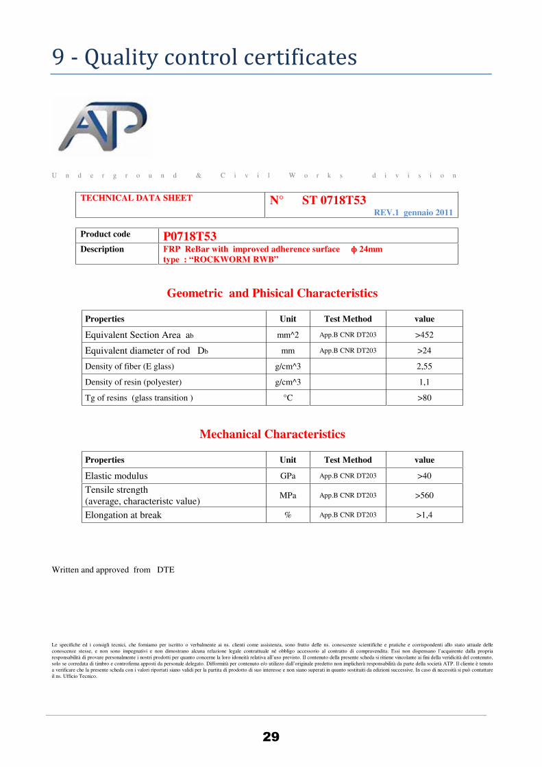
9 - Quality control certificates
29
U n d e r g r o u n d & C i v i l W o r k s d i v i s i o n
TECHNICAL DATA SHEET N° ST 0718T53 REV.1 gennaio 2011
Product code P0718T53 Description FRP ReBar with improved adherence surface ф 24mm
type : “ROCKWORM RWB”
Geometric and Phisical Characteristics
Properties
Unit Test Method value
Equivalent Section Area ab mm^2 App.B CNR DT203 >452
Equivalent diameter of rod Db mm App.B CNR DT203 >24
Density of fiber (E glass) g/cm^3 2,55
Density of resin (polyester) g/cm^3 1,1
Tg of resins (glass transition ) °C >80
Mechanical Characteristics
Properties
Unit Test Method value
Elastic modulus GPa App.B CNR DT203 >40
Tensile strength (average, characteristc value)
MPa App.B CNR DT203 >560
Elongation at break % App.B CNR DT203 >1,4
Written and approved from DTE
Le specifiche ed i consigli tecnici, che forniamo per iscritto o verbalmente ai ns. clienti come assistenza, sono frutto delle ns. conoscenze scientifiche e pratiche e corrispondenti allo stato attuale delle conoscenze stesse, e non sono impegnativi e non dimostrano alcuna relazione legale contrattuale né obbligo accessorio al contratto di compravendita. Essi non dispensano l’acquirente dalla propria responsabilità di provare personalmente i nostri prodotti per quanto concerne la loro idoneità relativa all’uso previsto. Il contenuto della presente scheda si ritiene vincolante ai fini della veridicità del contenuto, solo se corredata di timbro e controfirma apposti da personale delegato. Difformità per contenuto e/o utilizzo dall’originale predetto non implicherà responsabilità da parte della società ATP. Il cliente è tenuto a verificare che la presente scheda con i valori riportati siano validi per la partita di prodotto di suo interesse e non siano superati in quanto sostituiti da edizioni successive. In caso di necessità si può contattare il ns. Ufficio Tecnico.

U n d e r g r o u n d & C i v i l W o r k s d i v i s i o n
ATP srl Via Casa Pagano 31 Angri (SA)
We certify that the material, as per invoice mentioned , has been verified in according to product specification. Section area is not less than 452 mm*mm that is equivalent to a 24 mm equivalent diameter. Physical characteristics are congruent with technical data sheet N° ST 0718T53 in attached, while mechanical characteristics are to be considered reduced of 50% for effect of “bended version”.
Angri 00/00/10 resp. Assicurazione Qualità ATP s.r.l.
ATTESTATO DI CONFORMITA (CONTROL CERTIFICATE) N° ddtxxx
TIPOLOGIA PRODOTTO/PRODUCT DESCRIPTION
FRP STIRRUP ( closed ring and open type ф 24mm EQUIVALENT DIAMETER )
CLIENTE/CUSTOMER AGP XXX YYY ZZZ - -
Rif. Cliente Orde. E20600719 in date 31/05/2011
Rif. ATP Order 11 I 74
DDT (CMR) 00188 in date 07.06.2011
Quantity: Closed ring: Dim 1473x1272 tot length 334,89; Dim 585x1272 tot length 226,31;Dim 245x1272 tot length369,66 Open type : Dim2160/740/67° tot length 707,6
PRODUTTORE/MANUFACTURER: ATP srl Via Casa Pagano 31, 84012 Angri (SA) Italy
30

31

10 - Handling and Placement
Clamps/connectors (utilized to connect steel to fiberglass cages)
To allow handling and positioning of GRP cages it is recommended to use some steel plates fixed to the cage at the
ends (look at images below); these plates should be utilized for hooking the assembled cage.
The images below represent an example of the application where the steel plates utilized have dimensions
2000*200*20 mm. to fix n° 15 couples of GRP 32 mm. diameter rods.
The assembly design is the one shown in the next figure.
The clamps are composed by FE42 steel plates with
dimensions 100*40*20 mm. with n° 2 holes and n° 2 M16
bolts welded to the plate to facilitate the assembly on job
site.
32

Tests of clamps/connectors
The pull out strength of a couple of clamps can be verified by applying a load scheme as following:
The tests have been performed by applying fixing the hook to the fixed plate of a dynamometer (type LLOYD T50K)
and applying the load at the rate of 10 mm. per second; the load is measured utilizing a 50 KN load cell.
The nuts have been serrated with a dynamometric wrench set at 50-60 Nm.
Number 5 tests have been run with the following results:
Test n° 1 2 3 4 5
Max load (kN) 12.3 12.2 11.9 12.2 12.1
An average value of 1200 kg has been calculated. To be noted that at reaching the maximum load values it has been
experienced slipping of the GRP bars.
The above indicated values should be utilized for the design and determination of the number of clamps necessary,
obviously taking in the account the total weight of the cage. For the calculation a safety factor usually 3 should be
applied.
33

Handling and positioning in site of assembled GRP cages.
Handling to position the cages in place is performed by utilizing steel plates (see figure 9), bolted to the vertical rods
(see figure 10).
Figure 9 Detail handling steel plate.
The positioning plates can be removed once the cage is in place.
The coupling of any two cages can be done by utilizing steel couplers which will rigidly clamp the bars (see figure 11).
In the figure we are showing a typical connection of n° 2 cages either both GRP or one GRP and one steel.
barrae esterne
tipo V-1
barrae interne
tipo V-1
metallica
piastra
serraggioganci di
barrae esterne
tipo V-1
uncino di
serraggio
metallicapiastra
barrae interne
tipo V-1
manicotto
barre gabbia
in acciaio
barre gabbia
superiore
inferiore
bulloni difissaggio
manicottoin acciaio
bulloni difissaggio
superiorebarre gabbia
inferiorebarre gabbia
Figure 10 Positioning of lifting plates
Figure 11 Detail of connection between 2 cages
34
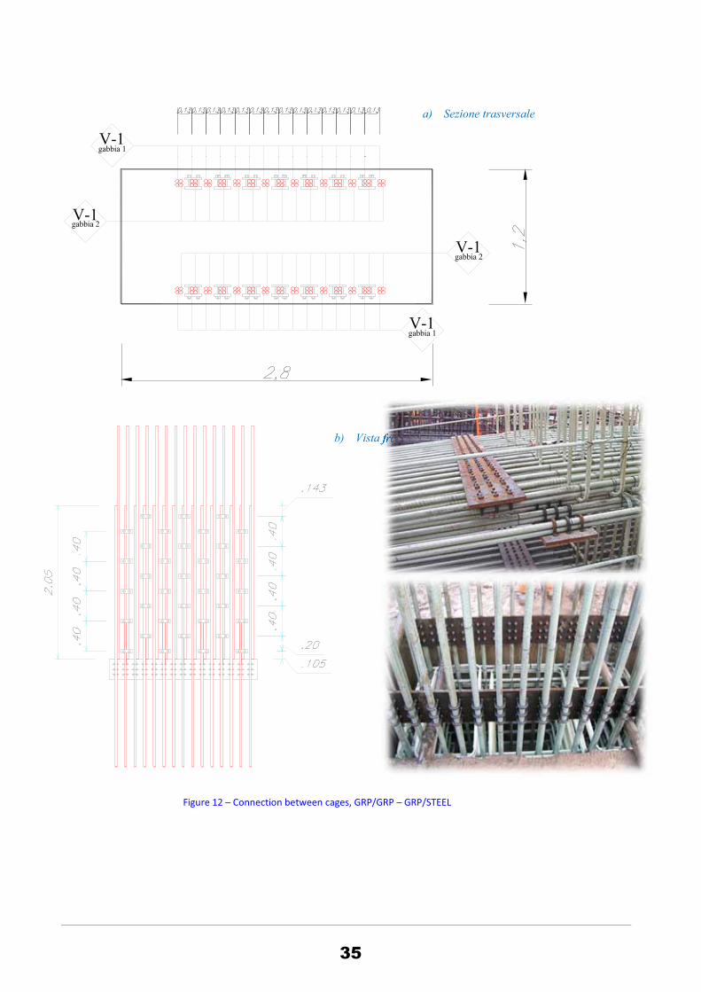
Figure 12 Connection between cages, GRP/GRP GRP/STEEL
V-1gabbia 1
V-1gabbia 1
V-1gabbia 2
V-1gabbia 2
a) Sezione trasversale
b) Vista frontale
35

11 - References projects and jobs
1. Corralito II - UTE AVE Girona
2. Estació Putxet - L9
3. Girona Puntales
4. Metro de Panama
5. OHL Toronto
6. UTE Sabadell
7. Anas PA 12-09 Agrigento Caltanisetta
8. Asti Cuneo pali e tiranti
9. Autostrada A1 Barberino Firenze Nord - Pali RWB ingresso fresa
10. Autostrada A1 Incisa Valdarno - Sottopasso Ferrovia
11. Catanzaro Lido-Lamezia Maire
12. Claudio Salini - Gallerie Italfer Arcisate Stabio - pali trelicon
13. FER.RO.VIT. pali 1000
14. Firenze Nodo AV Coopsette
15. Fortorina pali RWB
16. Metro Salonicco
17. Cattolica Demoter Italferr
18. Gabarit C Cattolica
19. Geodata per gara in India
20. Ghella Galleria Sappanico A14 - pali RWB
21. Gioiosa Anas CZ 01-05
22. GLF Anas ASR17 Serra Tonda Paratia Fi 1000
23. Hong Kong XRL project
24. IGT Camaldoli pali rock 1000
25. Impregilo - Ponte Stretto Pali Imbocchi gallerie
26. Impresa SpA Siena pali RWB
27. Metro Napoli Linea 6
28. METROB1 ROMA
29. METROC Linea C Roma Metropolitane
30. Metropolitana Brescia
31. Metropolitana MILANO Linea 5
32. Metropolitana Napoli Linea 6 prolungamento a Bagnoli
33. OHL-TULLY Harbor Siphon Replacement New York
34. Pedelombarda Galleria Solbiate Imbocco Sud - Pali RWB
35. Pizzarotti - Anas DG3904 - SARC4
36. Pozzo Parco City Life
37. SAMAC A14_Lotto 4_diaframmi imbocchi galleria
38. Terni Rieti gabbie sottoattraversamento
39. Toledo stazione Napoli Astaldi
40. TOTO Costruzioni Pali RWB GALLERIA SPARVO - IMBOCCO SUD
41. UTE ESTACIONES LINEA 9 BESOS
36

Notes date
Sketch
ATP s.r.l.via Casa Pagano, 31 - 84012 Angri (SA) Italy - ph +39 081 94 77 77 (pbx) - fax +39 081 94 77 40

ATP
Civil engineering, environmental engineering and geotechnical engineering projects and jobs are
becoming more and more complex and operate at very large scale and needs of new cost effective
and environmental friendly solution are required.
The value of the overall project is no longer bound only to the quality of the single components, i.e.
to smart engineering solution and single simple product, but also to an efficient coordination of the
overall process and to the capacity of finding quickly the most convenient solution and strongly
related to cooperation between engineering and industry.
Efficient coordination and knowledge brokerage services require a deep insight in the engineering
domain, in industrial product availability and in informatics technologies capable of deliver services
and cross-link the designer-industry-client market.
The peculiarities of the ATP Group is a fortunate mix of know-how perfectly corresponding to the
market needs:
Flexible and dynamic R&D department .
Flexible and dynamic Production.
Reactive-Search and development of new products based on effective needs of the market.
ATP aims at offering new solutions to construction market applying the latest technologies available
in composite FRP materials.
ATP desires to establish a valuable worldwide connection becoming a reference point for FRP
composite solutions in the construction market.
ATP s.r.l.via Casa Pagano, 31 - 84012 Angri (SA) Italy
ph +39 081 94 77 77 (pbx) - fax +39 081 94 77 40