Embed Size (px)
Citation preview

Lfl
FINAL REPORT
for
NEW TECHNOLOGY HIGH EFFICIENCY AND HIGH STABILITY
COLOR MOTION VIDEO COMPRESSION SYSTEM
AooessionlFr --
NTIS GRA&IDTIC TAB E
Unannounced Isubmitted by ~ ~ i
AVELEX I Availability Codes
310 Bonifant Road ALai and-..r
August 15, 1984
DT1CELECTE
Contract N00014- 84-C-0676 NOV 14 19840for 1ab row=*amduiow" me 11 05 041
NEW TECHNOLOGY COLOR MOTION VIDEO COMPRESSION SYSTEM PAGE 1
SUMMARY
New video signal compression technology including a novelmathematical transform was previously developed by Avelex toprovide for low bit rate transmission of full motion monochromeimagery. The nature of this new technology has suggested thatchrominance might be added to provide full color imagery with a 5rather small increase in the bit rate required for transmissionabove that required for the monochrome transmission alone. Thesubject task was proposed to DARPA to demonstrate the feasibilityof a full color, full motion video compression system which couldbe used for Defense Department and other Government Agencies, aswell as commercial applications. Two signal processing techniques -were proposed for the DARPA work which have been implemented andexperimentally evaluated with successful outcomes, and the resultsherein reported. Additionally, a Videotape showing theexperimental results is submitted as auxilliary information tothis final report.\
BACKGROUND
A combination of Intra-frame and Inter-frame methods forcompression of full motion monochrome imagery has been developedby Avelex and others, albeit based on somewhat differenttechniques. Avelex previously developed the novel Triangle andPyramid mathematical transform methods, Ref 1, for compression ofaudio and video signals as well as a group of methods forInter-frame compression of video signals. Principal imageperformance break-throughs compared with any prior technology arethree-fold. First, the new transform does not require asub-dividing or "blocking" process of the image and hence does notgenerate artifacts relating to blocking which appear as mosaics ortiles superimposed on the image. Second, the interframe methods -
prevent any remnants from previous images in a sequence of imagesproducing motion imagery from appearing after they are no longervalid, regardless of the transmission channel capacity of the link .being employed or the amount of motion in the image. Third,relative motion between the camera and an object does not resultin image break-up, as happens with most other high compression "".video codecs. This latter capability permits use of the codec indifficult situations where relative motion between camera andobject can exist. To accomplish this performance within thelimitations of a fixed rate transmission channel, edges of objectsin motion may temporarily lose some definition while they remainin motion. The loss of resolution condition depends upon theamount of .aotion presented to the compression equipment relativeto the capacity of the transmission channel being employed. Undermany conditions the amount of image motion may not be enough to .result in loss of any resolution.
-- m
2, -""''. .'"', "" " ""%'""" "."'"'.• ' " " "• "% '"'"" """ """' ""'"" "'," 4". "", ,""""'1-'" ";""

NEW TECHNOLOGY COLOR MOTION VIDEO COMPRESSION SYSTEM PAGE 2
As well as performance advantages, the Pyramid Transformprovides economic benefits. Hardware required to perform thePyramid mathematical transform is substantially reduced from thatnecessary to perform the often employed Cosine Transform. ThePyramid Transform can be calculated using a "fast" calculationmethod in which only additions, subtractions and binary shifts arerequired whereas the Cosine Transform requires non-trivialmultiplications and complex arithmetic. Despite the simplicity of -.
Pyramid Transform calculations, the basis functions are all smoothand do not result in artifact generation when higher fraquencycoefficients are omitted or coefficients more roughly quantized.
Also, the Pyramid Transform employs basis functions which4 are naturally finite on the original two dimensional signal space,
which results both in a sparse calculation matrix and not havingto sub-divide or "block" the image into many mosaics prior toperforming the transform operation on each resulting blockindividually. By not having to "block" the image no tiling"effects are ever observable in a Pyramid Transform reconstructedimage.
It has been known since the work toward the adoption ofthe N.T.3.C. color television standard in the U.S. in 1954 thatthe human visual acuity to chrominance portions of an image, asopposed to luminance portions, is considerably less than requiredfor a purely black and white video transmission. This fact led tothe significant reduction in bandwidth required for transmission --
of chrominance portions of video and, along with the developmentof a novel frequency interleaving technique, the ability totransmit both monochrome and chrominance portions of an image inthe same bandwidth as previously required for monochrometransmission alone.
* Also, the N.T.S.C. technique inherently relies on the factthat the chrominance portions of the image have a high degree ofspatial correlationi with their monochrome counterparts, at leastfor television receivers which do not completely separate thechrominance subcarrier from the directly displayed monochrome"component prior to display. Difficulty arises with the basicassumption that a chrominance subcarrier will be invisible to ahuman ob3erver. Although the subcarrier frequency has beenselected to be an odd multiple of one-half the line rate andshould, with the aid of persistence of vision, add to themonochrome component in one frame and subtract from it during thenext resulting in visual subcarrier cancellation, the non-linearcharacteristic of the picture tube employed causes incompletecancellation of the resulting brightness of the two frames. The"presence of the subcarrier added to the monochrome video signaland directly applied to the luminance of the video display device
a. actually increases the output brightness of the image to a degreeproportional to the saturation of the color (amplitude of thesubcarrier) in a particular area. If dramatic color saturation
S:: '<" :'": '------------------------ '"---* ?: :.-,.*** ,'.. . . . . . . . . . .. * *:::::::::=============================================

NEW TECHNOLOGY COLOR MOTION VIDEO COMPRESSION SYSTEM PAGE 3
changes were to occur in an image area wherein the brightnesscomponent remained constant, the perceived brightness wouldactually change. However, the natural correlation betweenchrominance changes and luminance changes results in theaforementioned effect not being troublesome in practice. Anexample of the effect of the monochrome signal from a first videosignal and the chrominance signal from a second source transmittedas a single encoded signal is given in Ref 2, page 213. Whenreceived and displayed on a monochrome receiver the effect of thebrightness alteration due to the chrominance signal is veryapparent. However, when the monochrome and chrominance signalsare both taken from the same source, any resulting distortion ofthe luminance signal is not apparent.
The first of the two aspects of the work of this projectto be demonstrated relies on the lower human visual acuity tochrominance image portions relative to monochrome portions, toeffect an efficient transmission of color image components. Thesecond aspect takes advantage of the usually natural alignment ofimage transitions (edges) between chrominance and monochromecomponents of the same image to more efficiently encodechrominance components for transmission. This latter efficiencyresults from using the same, or nearly the same, overhead mapwhich signals the receiver where to utilize non-zero valuemonochrome transform coefficients to also signal the usage of thetransmitted non-zero value chrominance coefficients.
The motivation for the belief that these aspects of thetask wriuld work are as follows. The Pyramid Transform has astrong frequency characteristic and consequently the resultingtransform coefficients represent specific spatial frequencies inan image. Therefure, if human visual spatial acuity is frequencylimited to a predetermined degree, it should be possible to omitfrom transmission transform coefficients representing spatialfrequencies above those which are observable. The receiver, as aresult of this process, will be pre-programmed to assume that thenon-transmitted higher spatial frequencies of the chrominancecomponents have a value of zero and accordingly reconstruct achrominance image component with less detail. Secondly, the factthat chrominance edges are primarily co-located with monochromeedges in naturally occurring images leads to the presumption thatnon-zero value transform coefficients for chrominance componentsfor the Pyramid Transform occur in the same locations as theirmonochrome counterparts. This latter presumption arises becausethe Pyramid Transform yields zero-value transform coefficients,which are not transmitted, in all smooth image areas and non-zerovalue coefficients, which are transmitted, only in areas whichpossess changes or edges. In this regard, smooth is defined asmeaning any image area wherein the monochrome or chrominance imagecomponent has a constant or spatially linearly varyingcharacteristic.
- - -. . . ... > . . . .. . . . . . . . . .. - . . . .. .

NEW TECHNOLOGY COLOR MOTION VIDEO COMPRESSION SYSTEM PAGE 4
THE TRIANGLE AND PYRAMID TRANSFORMS
The Triangle and Pyramid transforms are respectively oneand two dimensional signal transforms which are fully described inRef 1. Of first interest for this task are the Fourier Transformsof the basis functions of the Triangle and Pyramid transforms soas to determine what frequency groups are carried by whichtransform coefficients. This is of direct use in determiningwhich Pyramid transform coefficients are required to obtain acertain desired spatial frequency response for chrominance imagecomponents.
The one dimensional Triangle Transform is most readilydiscussed without the complication of the second spatialdimension. The Pyramid Transform involves almost identicalapplication of two Triangle Transforms, one in a directionorthogonal to the other, a process usually employed in other twodimensional transformations. Thus a basis function having atriangular shape in one dimension has a pyramid shape in twodimensions.
The Triangle Transform is organized into a number ofbands, Bands 1 through N, each having coefficients, and the Band 1also having so-called "B" functions. The value of N can vary overa rather wide range, but has been selected as five for the presentdiscussion. In the forward transform direction a decimation isperformed using triangular weighting functions and coefficientweighting functions shown in FigLre 1. The coefficients have theuseful property that input samples which form a straight line overthe span of the coefficients' footprint result in zero values,which usually do not require transmission in a video compression . -
system. This property is extremely advantageous in providing foroperation of the second part of this contract work to be discussedlater. The coefficients resulting from the first decimation arecalled the Band N coefficients.
For an input signal having P samples there are P/2triangular function outputs, also called "B" functions, and P/2coefficients in Band N. For a two dimensional input signal thereare P/4 "B" functions and 3*P/4 coefficients. The coefficientsreceive no further transform processing whereas the "B" functionsprovide the signal inputs to the Band N-i processing.
The operation of the Band N-i processing is identical tothat of Band N and results in "B" functions and coefficients.Figure 2 shows the important result that performing two successivetriangular decimations is itself a triangular weighting functionof the original input samples. The triangular weighting functioncentered on P3 yields B52; the weighting function centered on P5yields B53 and so forth. In the next lower band the weightingfunction which is twice as wide as the Band N function and

-4
NEW TECHNOLOGY COLOR MOTION VIDEO COMPRESSION SYSTEM PAGE 5
centered on B53 yields B41. The equations for the weightingfunctions are as follows:
B52 - 0.25*P2 + 0.5*P3 + 0.25*P4,B53 - 0.25*P4 + 0.5*P5 + 0.25*P6, andB54 - 0.25*P6 + 0.5*P7 + 0.25*P8, such that,
B41 - 0.25*B52 + 0.5*B53 + 0.25*B54, or,
B41 - 0.25*(0.25*P2 + 0.5*P3 + 0.25*P4)+ 0.5*(0.25*P4 + 0.5*P5 + 0.25*P6)
+ 0.25*(0.25*P6 + 0.5*P7 + 0.25*P8).
B41 = (1/16)*P2 + (2/16)*P3 + (3/16)*P4 + (4/16)*P5+ (3/16)*P6 + (2/16)*P7 + (1/16)*P8.
Thus the weighting function in each successive lower bandis another triangular function with twice the width and half theheight of the preceding higher band. Although all triangularweighting functions below Band N have non-trivial (not a power ofthe base two) multipliers, the process of progressive decimationachieves the desired lower band weighting functions withoutperforming any non-trivial multiplications.
The frequency response of the triangular function isreadily found via the Fourier Integral and an input triangle ofheight V and width at the base of 2*T to be:
F(W) - V * T * (XI*XI), where X1 - SIN(W*T/2)/(W*T/2).
The familiar Sin(X)/X function has its first zero at X-pi (pi-3.14159) or equivalently at W - 2*pi/T. Sinve T has been shown todouble in each successive lower Band and since W and T arereciprocally related, the value of W where the frequency responseis first zero in each band decreases by a factor of two for eachsuccessive lower band.
The frequency response of a five band transform system isshown in Figure 3. From this it can be seen that the differencebetween the input signal bandwidth and the Band 5 "B" functionbandwidth, taken at the 85% point is about one octave. We candeduce therefrom that the Band 5 coefficients occupy primarily thefrequency spectrum from one half the maximum to the maximum inputsignal frequency. By similar reasoning the Band 4 coefficientsoccupy a spectrum primarily between one fourth and one half of themaximum input frequency.
Applying this to the constructed experimental systemwherein the sampling frequency is 9.5 MHz. and the maximumpermitted input signal bandwidth is 4.75 MHz. the TriangleTransform coefficients in one dimension are seen to roughly occupythe following frequency regions:
. .,.. - * * * * . .,

NEW TECHNOLOGY COLOR MOTION VIDEO COMPRESSION SYSTEM PAGE 6
BAND FREQUENCY RANGE - MHz."2.375 to 4.75
4 1.19 to 2.3753 0.6 to 1.192 0.3 to 0.6
The horizontal bandwidths specified for tra-,ismissior, ofchrominance components for the commercial color system in theUnited States are:
I Axis: 0 to 1.3 MHz.Q Axis: 0 to 0.5 Mhz.
The I axis corresponds to the axis of maximum visual acuity andoccurs for tolors in the red and orange regions. The Q axiscorresponds to the axis of minimum visual acuity and occursprimarily for colors in the magenta region.
The present study has considered transmission of only thelower bands of coefficients, along with the Band 1 "B" functionsfor the I and Q chrominance axes. Specifically considered havebeen the following systems:
Band 3 Bans 2 "B Band 2 Band 2C Band 2 Band 1 'D Band 1 Band 1 "B" functions only.
The Band number indicates the maximum band for whichnon-zero value coefficients are transmitted. Coefficients inhigher bands are not transmitted and at the receiver are assumedto be zero.
System A is roughly representative of the N.T.S.C.specification relative to horizontal frequency components altho'ughthe image display device used (a typical device) does not displayany chrominance components higher than the Band 2 of the Triangleand Pyramid Tran3form.
SPECIFIC WORK OF THE DARPA TASK
The Avelex work has been first to construct necessaryhardware and software to convert, a pre-ex sting breadboard formonochrome image compression to that capable of processing andcompressing full color motion imagery. To accomplish this thepreviously existing breadboard Pyramid Transformer has been timemultiplexed so as to transform, in the language of the N.T.S.C.Video specification, the Y (monochrome), and the chrominance "I"
7"%',

NEW TECHNOLOGY COLOR MOTION VIDEO COMPRESSION SYSTEM PAGE 7
and "Q" signals in sequence at the transmitter. This accomplishesthe complete transformation of all three separate video componentsinto Pyramid transform coefficients. Several new breadboardcomponents including frame stores have been added and/orconstructed to do this. Second, software for a personal computerhas been written and implemented to control via simple keyboardentry all of the parameters relative to the research of this task.These include the Band number, which controls the frequency groups .used in compression of the chrominance components, and the mapformation method which determines whether the monochromesignalling map is used for signalling the presence of non-zerovalue chrominance coefficients or whether individual chrominancemaps are formed for such signalling. Also, combinations arepossible such that the "Y" and "I" maps can be formed and the "Q" 3.not formed but assumed to be adequately represented by the "Y"map.
Figure 4 shows the modifications of the Pyramid systembreadboard to accomplish the addition of the chrominancecomponents. The video Analog-to-Digital converter and digital ,,comb filter were pre-existing to separate the monochrome andchrominance subcarrier signal components from the encoded videoinput. A new chrominance digital to analog converter has beenadded followed by an analog chrominance demodulation system suchas to recover the "I" and "Q" baseband video signals. Filters in 'the demodulator limit the "I" bandwidth to 1.5 MHz. and "Q" ..-bandwidth to 0.5 MHz. The "I" and "Q" baseband sigals are thentime multiplexed and converted to digital video signals in a sixbit Analog-to-Digital converter. New frame stores receive thedigitized "I" and "Q" signals to store them until they can beprocessed in sequence in the single forward Pyramid Transformer.The "Y" signal is delivered to the Transformer directly withoutneed of a frame store but the "I" and "Q" signals are saved overfrom the same frame that was used for capture of the "Y" signal.The electronic switch ahead of the transformer allows the forwardPyramid Transformer and forward Coefficient Processor, previouslyimplemented, to process in sequence the "Y", "I" and "Q" videoframes from the same video input frame.
At the receiver the same previous ReconstructionCoefficient Processor and Pyramid Reconstruction Transformer areused in sequence to reconstruct the "Y", "I" and "Q" video signalsand place them in frame stores to be subsequently displayed by thereceiver. Two frame stores are used for each of the three signalsin a ping-pong fashion to permit simultaneous switching of thesame Y-I-Q video frame combination to the display device at onetime. That isp while one trio of frame stores is serving torefresh the receiver display, the second trio is receivingsequentially the next "Y", "I" and "Q" video components. A newDigital-to-Analog converter trio and a N.T.S.C. encoder togenerate a composite color video signal for output display havebeen constructed.
p
".................... ." '" ' ". " "" " "" """ " '-,''';'''...'i',"..'.,.--.?i.r.:,

NEW TECHNOLOGY COLOR MOTION VIDEO COMPRESSION SYSTEM PAGE 8
CALCULATED CHROMINANCE PYRAMID Tr.ANSFORM EFFICIENCY
In a previous section on the explanation of the Triangleand Pyramid Transforms the relationship between the bands of thetransform and the frequency spectra they occupy was established.It was shown that the coefficients of the top band of thetransform occupied primarily the top half, or octave, of thefrequency spectrum; the next lower band coefficients occupiedprimarily the next lower octave which is one half the width infrequency of the top octave, and so forth. The pro osal for thisDARPA contract postulated that it should be possibl to omit fromtransmission the coefficients of one or more of the higher bandsof the Pyramid Transform since these bands correspond to spatialfrequency components higher than those usually observable by thehuman eye. At the receiver, the omitted coefficients are giventhe value of zero and the reconstruction transform subsequentlyperformed.
The efficiency to be gained by omission of the higher bandPyramid chrominance coefficients can be determined mathematically.The total number of transform elements developed for a munochromeimage transformed by the Pyramid Transform into five bands is:
1. 44E B (1 + 3*(1 + KO + K0 + KO + K0)).
where .B is the number of Band 1 "B" functions and K0-4 for thecase with no compression. For a typical B-240 (16 horizontal by15 vertical), this yields 245,760 elements. Due to the ability ofthe Pyramid Transform to remove redundancy and hence produce manyzero value coefficients which do not require transmission theequation can be modified to include empirically observed factors"A" and a smaller KO"
W - B * (1 + 3*A*(1 + KO + KO + KO + KO ))
Herein it is assumed that all values of the Band 1 "B" functionsrequire transmission and that "A" represents the fraction of Band1 coefficients which are typically non-zero and is observed to be0.8. KO is about 2 for a five band system. The ratio "R" oftransform elements to non-zero value transform elements can becalculated as:
L4B * (1 + 3*(1 + (4) + (4) + (4) + (4) )
R 3 , or,B, (1 + 3*0.8*(1 + 2 + (2) + (2) + (2))
1 + 3*(1 + 4 + 16 + 64 + 256)R I .or,
1 + 2.4*(1 + 2 + 4 + 8 + 16)
R - 13.58.
• ' "- .'.•:'i",i•'i. ?,• '.-',,';-'.?.?',..; "," .;" .'.', .'..'.......,.........,.'.............,.....,-....,...........-.,,..-...-,. -, ,'-. ... .'....'..'.,,'.

NEW TECHNOLOGY COLOR MOTION VIDEO COMPRESSION SYSTEM PAGE 9
The value of 13.58 will be used as a typical value for singleimage monochrome compression prior to any additional compressionobtained by variable length (Huffman) coding of the transformcoefficients.
The following calculations assume that all coefficients ina particular band are omitted from transmission when it isdetermined to exclude coefficient elements from that band. Theresult is that both vertical and horizontal resolution aredecreased by the same amount. This is in contrast to the N.T.S.C.practice of decreasing only the horizontal resolution. Thejustification for decreasing the resolution in both directions isthat the human observer has no better chrominance acuity in onedirection than another.
Although calculation results could be herein reported forincreased efficiency due only to elimination of higher bandchrominance data to be transmitted and not to other efficienciesdue to transform compression, such numbers do not reflect theactual chrominance to monochrome ratios in practice. It shouldalso be shown that there are monochrome efficiencies, and thatefficiencies accrue more to redundancy removal in the higher bands. the very ones being eliminated in the present chrominance case.
The first case concerns "I" coefficients up through Band 3and "Q" coefficients through Band 2. The relative amount of dataresulting, relative to the monochrome operation, is:
"I" data + 11Q11 data1+
Monochrome data
and the fraction of data in excess of the monochrome data is:
"I" data + "Q" dataF- ,or,
Monochrome data
(1 + 2.4*(1 + 2 + 4)) + (1 + 2.4*(1 + 2))F-
1 + 2.4*(1 + 2 + 4 + 8 + 16)
17.8 + 8.2F-
75.4
F - 0.3448, or F - 34%.
The results of similar calculations for this and othercombinations of "I" and "Q" resolution relative to "Y" resolution"are shown in Table 1.
--. . . . . . . .
.4 . . . Y

NEW TECHNOLOGY COLOPR MOTION VIDEO COMPRESSION SYSTEM PAGE 10
Table 1
"I" Band Q"Band "Y" Band F (Overhead for chrominance)5 34 %
2 2 5 22%2 1 5 15%1 0 (Note) 5 6 %
3 2 4 70 %2 2 4 44 %2 1 4 31%1 0 (Note) 4 12 %
Note: a "0" indicates that only Band 1 "B" functions are used.
The Table also shows the amount of overhead when' the monochromeBand 5 coefficients are omitted from transmission. Again, relativeefficiencies have been calculated without regard to additionalefficiency gained for both monochrome and chrominance componentsthrough use of variable length (Huffman) coding of the transformcoefficients.
USE OF MONOCHROME MAP FOR CHROMINANCE COMPONENTS
The second part of the task has been to experimentallyevaluate use of a common signalling map to signal the transmissionof non-zero value chrominance transform coefficients as well asthe non-zero value monochrome coefficients. The map used formonochrome signalling is shown in Figure 18 of Ref 1, and is atree structure method of signalling from the transmitter to thereceiver where to place the sub-set of non-zero value transformcoefficients also transmitted for use in the transformreconstruction process. The map is a relatively small amount ofoverhead compared with the transform coefficient data transmittedand is a ýery small amount of data compared with all of the zerovalue coefficients which, as a result of the use of the map, donot require transmission.
It was postulated in the proposal for this task that thesame map which is developed, based on the transform coefficientdata, for the monochrome, or "Y" component of the image could beused directly for the two chrominance components. Since the firstpart of this task explored use of only the lower bands of thePyramid Transform for transmission of chrominance coefficients,the monochrome map would be used for chrominance transformcoefficients only in those applicable lower bands.
A color video signal usually is initially generated by acamera which divides light coining through its lens into Red, Greenand Blue primary color separations, these being the three additiveprimaries used for color television imagery. The Red, Green and
S. . . . . . . . . - .. ... ..... .= . .. • ,• .- ,--...... ... , -

NEW TECHNOLOGY COLOR MOTION VIDEO COMPRESSION SYSTEM PAGE 11
Blue (R, G and B) signals are taken as three independent variablessince any combination of them is possible at any spatial locationwithin an image. The monochrome "Y" signal and the twochrominance signals, " and "Q" are formed as different linearcombinations of the R, G and B signals by,
Y - 0.299*R + 0.587*G + 0.114*BI - 0.596*R - 0.274*G - 0.322*B
- 0.211*R - 0.523*G + 0.312*B
The "Y" signal represents the luminance value of the color signal.Both the "I" and "Q" signals have zero amplitude for the R-G-Bcondition corresponding to any non-colored portion of an image.The Y, I and Q signals are used in the present task of developingtransform coefficients for transmission. At the receiver aninverse matrix of Y, I and Q signals yields the R, G and Bsignals:
R - I.O*Y + 0.956*1 + 0.621*QG - 1.0*Y - 0.272*1 - 0.647*QB - 1.O*Y - 1.106*1 + 1.703*Q
Due to the independence between the R, G and B, andbetween the Y, I and Q signals there is nothing from the algebrato suggest any commonality between them which would indicateredundency and hence the opportunity for compression. However, .the R, G and B signals in practice are very highly correlated witheach other when originating from natural scenes. Ref 2, Figures7-11 and 7-12 between pages 194 and 195 show a color image withaccompanying photographs of R, G and B, and Y, I and Q separationswherein the high degree of correlation is quite observable.
Correlation in the present context really refers to thesimilarity of the spatial locatiun of changes between the Y, I andQ signals. Due to the nature of the Pyramid Transform and itsfinite and generally narrow footprint on the image signal this"1"change" correlation in the R, G and B signal domain carries overwell into the transform coefficient domain. This is in coni'rastto most other transformations wherein each of several coefficientsis usually a function of all of the same points in the originalsignal space. In this latter case considerably more points areusually weighted and summed over the same signal space tocalculate each of the coefficients, resulting in a loss ofcorrelation between a particular coefficient and a spatiallocation. Relative to the Pyramid Transform and morespecifically, the aforementioned changes refer to departures fromspatial linearity of the image separations.
It is known that no non-zero value transform coefficientsare generated by the Pyramid Transform for image areas where theintensity of the input signal varies linearly with any spatialdirection. Also, the system is configured to transmit only
°. - ' . - -* 4 W" 44 4

NEW "LCH•T1%OGY CGLOF MOTION VIDEO C0,..PRE"SION SV.TEM PAGE 12
non-zero ialue coefficients as directed by the sienalling map. Themap system accompaying the Pyramid Transform monochromecoefficients serves to indicate any non-zero value coefficientregavdless of its algebraic sign or absolute value, if above asmall threshold which qualifies it for transmission. Since themap signals no information concerning signa polarity oramplitude, a chrominance coefficient at the same loc cion in thetransformation process can have an arbitrary polarity andamplitude relative to its monochrome counterpart and its presencebe adequately signalled to the receiver by the monochrome mapcomponent.
Although the aforementioned correlations are in practicevery strong there is no guarantee of their existence 100% of thetime. Two cases exist where a mistake can be made. The firstkind of mistake occurs where a monochrome bLt no chrominancechange occurs, and a map component generated and transmnitted. Azero value ehrominance coefficient is transmitted as a resultwhich does not produce a reconstruction transform error but causesa transmission inefficiency to occur. The second case existswhere a non-zero value chrominance component occurs but a zerovalue monochrome component exists. In this situation thechrominance component is not transmitted and a chrominancereconstruction error occurs. Depending upon the amplitude andBand number, the error may or may not be visible in thereconstructed image.
-,7-.

,.7 •
NEW TECfrNOL'q Y COLOR MOTION VIDEO COMPRESSION SYSTEM PAGE 13 ::,
RESULTS AND CONCLUSIONS --
Construction of electronics to add chrominance capability 1:to the Avelex Pyramid Transform experimental system has been..icomnp leted with all systems functioning satisfactorily. Tests !employing a standard Color Bar pattern at the analog input to the •:.compression system show all test colors at the reconstructed •output to be within hue and saturation specifications as measuredwith a standard N.T.S.C. Vectorseope. "!i
Part 1. of the demonstration task has been to show and :.•evaluate color images which have been compressed using the Pyramid _Transform, have then had certain higher band coefficients of the •..two chrominance signals 'II" and "Q" discarded, and the images then
Sreconstructed from the remaining coefficients, First, the effectSof decreasing vertical color resolution as well as horizontal •'
color resolution, compared with the N.T.S.C. practice of only •i!decreasing horizontal color resolution, is completely acceptable -in visual appearance to the point of going unnoticed, except in •..cases of quite careful observations. Situations where a i.difference in color performance can be noticed between reducing 'iiand not reducing vertical color resolution occur where vertically .narrow and horizontally wide colored areas exist, as in the case 'of letters of the alphabet in color. The letter "T", when -.occupying a very small part of the image area can be taken as an ..example. In the N.T.S.C. system, the horizontal line forming the-•itop of the letter shows full chromaticity whereas the vertical •<'Sline forming the stem of the lette*r shows reduced saturation of..-
Sthe color. The Pyramid Transform reconstrurcted letter "T" using-'-.lower resolution in both horizontal and vertical directions showsreduced color saturation of both parts.--
Of concern prior to construction and evaluation of the -'color processing to effect reduction in resolution of the color iisignal components was the possibility of visib~y objectionablealiasing in the reconstructed image. This could result since .the'-bands of the Pyramid Transform are only moderately frequency •-iselective and failure to limit the frequency range of the input i.i.color components commensurate with the highest band used for ;.-chrominance transmission could result in aliasing. This effect .. •has previously been observed with the monochrome signal. The...:
Scolor aliasing effect, although it does occur, is fortunatelyvirtually unobservable. To be able to see the eliasing one must"
Sview a highly saturated color at very close range to the receiver '"and be searching for it. •!?
The efficiency of transmission with reduced horizontal and ['color resolution is very significant. Considering that threesignals must be transmitted to effect a reconstructed color image, ..as opposed to a single signal to effect a monochrome image, a 200% -..overhead relative to the monochrome signal is necessary to .•'

NEW TECHNOLOGY COLOR MOTION VIDEO COMPRESSION SYSTEM PAGE 14
transmit a color signal without considering any chrominanceresolution reduction. It was shcwn in Table 1 that thechrominance overhead could be reduced to between 6% and 34% for afull 5 Band system with monochrome resolution of 504 H * 480 V.For a 4 Band system with monochrome resolution of 252 H * '240 Vresolution the chrominance overhead could be reduced to between12% and 70%. In both cases the overhead percentage depends on thechrominance resolution transmitted. In general it has not beenpossible to distinguish the difference by observation of usingBand 2 coefficients for the "I" chrominance signal relative tousing Band 3 coefficients. Since the "I" signal corresponds to achromaticity axis to which the eye is more spatially sensitive itwould at first seem that greater detail should be observable withthis signal than Band 2. However, most color receivers, includingthe one used for this experiment, e iot process any color in thehorizontal direction above the i equencies covered by Band 2.Thus one would not really expect to see horizontal colorimprovement when the Band 3 chrominance is added. Improvement inthe vertical direction by adding Band 3 chrominance appears to besmall for naturally occurring scenes. For a color system in whichBand 2 is used for both "I" and "Q" signals, the chrominanceoverhead for a Band 5 monochrome system is 22% and for a Band 4monochrome system is 44%. Chrominance resolution reduction byanother factor of two in each spatial direction is still quitesatisfactory for teleconferences and other applications wherechromaticity does not have to be observed in great detail andyields overhead relative to the monochrome signal of 15% for aBand 5 system and 31% for a Band 4 system. Further chrominanceresolution is possible and is not unacceptable. However, generalcolor saturation is observed to be slightly reduced. The overheaddrops to 6% and 12% respectively as a result.
Part 2 of the task has been to evaluate the ability of themonochrome ("Y") signalling map to adequately be used by the twochrominance signals to also signal their non-zero valuecoefficients. The experiments show, by observation, thatsignalling of the "Q" component is satisfactorily signalled by themonochrome map for all of the various chrominance resolutionreduction systems tried. The results for the "I" component,however, show an occasional observable chrominance error by usingthe monochrome signalling map. The errors do not appear whenusing the "I" map directly so the errors seem directly traceableto the monochrome map. The observed errors are sufficiently largein spatial extent to conclude that they probably occur in Band 1coefficients rather than Band 2 or higher coefficients. Thus thecorrelation between chrominance changes and monochrome ones isvery good, but not 100% for the "I" signal.
Another method to cause the "I" signal to be completelysignalled without actually transmitting a separate "I" map ispostulated and should solve the observed problem. The method isto produce a logical "OR" of the "Y" and "I" maps, at least for
_ *j- -..-:':•.•-:.:*:~** . -. v * ~ - . ~ * ' <

NEW TECHNOLOGY COLOR MOTION VIDEO COMPRESSION SYSTEM PAGE 15
Band 1 and to transmit that instead of the "Y" map. Transmissionof all non-zero values of both the monochrome and "I" signals isthus guaranteed. A small amount of inefficiency results in thatsome zero value monochrome coefficients are transmitted. However,this is judged preferable to the transmission of a completelyseparate "I" signalling map. The constructed hardware did notpermit this case to be experimentally tried and evaluated.
The chrominance Band 1 "B" functions foxm the foundationfor the color in a particular Pyramid Transform reconstructedimage and are adequate to reproduce the correct coloring in allareas of an image, although the color resolution is less thandesired. These Band 1 "B" functions can always be transmittedeven at very low transmission channel capacitieb and withcontinuous motion in the entire image since there are only 240total "I" and 240 total "Q" of these elements in a color imageframe. Therefore no image break-up can occur in the chrominance(or the luminance) portion of the images as the basic Band 1 "B"function building blocks are always given first priority andtransmitted without delay. This stability is shown to occur inpractice with the experimental hardware. As transmission channelcapacity is or becomes available, the chrominance coefficients inBand I and those higher bands which are used for color can betransmitted to provide the desired chrominance resolution.
The efficiency of chrominance coding has been shown to bedependent upon the degree of resolution used in a particularsystem but to be substantially increased by not transmittingresolution which cannot be seen by an observer at the receiver.The efficiency is also increased by using an already existingmonochrome signalling map, or one perhaps slightly modified fromit to signal the non-zero value chrominance coefficients ratherthan requiring an extra and independent map for each of the twochrominance signals. The desired decrease in chrominanceresolution to achieve the desired efficiency is obtained by simplydiscarding coefficients in certain higher bands produced by theforward Pyramid Transformer and does not require any additionalspecial hardware.
APPLICATIONS
The Video compression technology developed under this taskand previously developed by Avelex provides a combination ofperformance and simple implementation such that portable,miniaturized, battery powered devices can be a reality forapplications including battlefield communications, covertoperations, remote sensor and video guidance systems.
"The video compression performance of the Avelex Codec hasbeen demonstrated by this task and through previous Avelex work.The technology behind the performance requires hardware which neednot perform multiplications or other high power drain operations,
M.. *,. ."*
NEW TECHNOLOGY COLOR MOTION VIDEO COMPRESSION SYSTEM PAGE 16
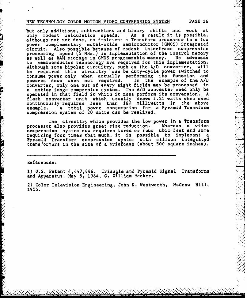
but only additions, subtractions and binary shifts and work at -
only modest aalculation speeds. As a result it is possible,although not yet done, to implement a Transform processor in a lowpower complementary metal-oxide semiconductor (CMOS) integratedcircuit. Also possible betause of modest interframe compressionprocessing speed (5 MHz.) is implementation of the control memoryas well as RAM storage in CMOS programmable memory. No advancesin semiconductor technology are required for this implementation.Although some bipolar circuitry, such as the A/D converter, willbe required this circuitry can be duty-cycle power switched toconsume power only when actually performing its function andpowered down when not required. In the example of the A/Dconverter, only one out of every eight fields may be processed in "-'.a motion image compresion system. The A/D converter need only beoperated in that field in which it. must perform its conversion. Aflash converter unit which usually draws 1.25 watts when usedcontinuously requires less than 160 milliwatts in the aboveexample. A total power consumption for a Pyramid Transformcompression system of 20 watts can be realized.
The circuitry which provides the low power in a Transformprocessor also provides great size reduction. Whereas a videocompression system now requires three or four ubic feet and somerequiring four times that much, it is possible to implement aPyramid Transform compression system with silicon integratedtrans."ormars in the size of a briefcase (about 500 square inches).
References:
1) U.S. Patent 4,447,886. Triangle and Pyramid Signal Transformsand Apparatus, May 8, 1984, G. William Meeker.
2) Color Television Engineering, John W. Wentworth, McGraw Hill,1955.
I..,
* ~ *' S I '-,
* ** -- -~ * *.,,*.'*-,',*..,*

r"Up01
23/3z
P3 PS
31,
'IN
FIG .-

&06
IV
tL
Gt-u
-. UU.
Ld~
LI)
c~ew

Ij
At 3
I aZu L
0 a
~~U~I.~iLOLL: u1