Embed Size (px)
Citation preview

FootMotionCaptureforFirefighter
ADesignProjectReportPresentedtotheSchoolofElectricalandComputerEngineeringofCornellUniversityinPartialFulfillmentoftheRequirementsfortheDegreeof
MasterofEngineering,ElectricalandComputerEngineering
SubmittedbyDiHuang,LiweiHan,YiningGong
MEngFieldAdivisor:JosephSkovira
MEngOutsideAdvisor:HuijuPark
DegreeDate:January2017

Abstract
MasterofEngineeringProgram
SchoolofElectricalandComputerEngineeringCornellUniversity
DesignProjectReport
ProjectTitle:FootMotionCaptureforFirefighterAuthor:DiHuang,LiweiHan,YiningGongAbstract:Atthepresenttime,thereisonlyanecdotalevidenceconcerningpossibledesignissueswithFirefighterboots.ThismotioncapturesystemisusedtodefinethepossibleproblemswhenFirefighterbootsarebeingused.Thesystemhasthreefunctions:
• datadetection• datacollection• datadisplay.
SV03Arotarysensorsarebeingusedinthissystemtodetecttheanglechangedataofankleofthe foot. Its biggest advantage is that it fits into the small room of Firefighter boots. DatacollectionpartusesArduinoUnomicrocontrollertorealizeitsfunction.Oncetheanglechangehasbeendetectedbythesensor,microcontrollerwillfilterthedataandtransferitfromvoltagetoangledataandfinallystoreitlocallyonaSDcardbyusingtheSDcardshield.Lastfunctionforthissystemistodisplaydatainanimationform.Afterfinishingcollectingdatainanexperiment,datawillbeuploadedtoaProcessingprogramanddisplaythedataoutinananimationform.

1
Individualwork
DiHuang:--Tookactivepartinthesensorselectionprogress.Proposedtheshortcomingsofapplicationofaccelerometerandopticalsystem.Sparkedtwo
otherwaystorealizethisproject:angularsensorandRFIDapproach.--Foundanidealsensorfittinginourspecificdesignrequirementforsize.--FulfilledthelinearityverificationtestasmentionedintheimplementationpartwithLiwei.--Cameupwiththeprimaryideaabouthowtoplacethesensoronfootandtheset-upforthe
sensorpart.--Builtupthefirstversionofthesensorcomponent(theonewithwoodenstick)asdescribedin
thedesignpartforsensorwithLiwei.--DrewthestereomodelinAutoCADfor3Dprinterwiththehelpofmydadtobuildupthesecond
versionofthesensorcomponent(theplasticoneprintedwith3Dprinter)asdescribedinthedesignpart.
--FulfilledtheprogrammingworkwiththesoftwareProcessing,whichisproposedbyLiwei,tovisualizetheangledataproducedbyArduino.
--Tookpartinimplementingalltheexperimentsasmentionedintheimplementationpart.--Didthedocumentationaboutdiscussionsandmeetings,aswellasexperiments.LiweiHan:--Helpselecttheappropriatesensorforthisproject.--TesttheSV03Arotarysensor.--AssembletheSDcardshieldwithmicrocontroller.--Buildcircuittoconnectsensorwithmicrocontroller.--Programthemicrocontrollertocollectdata.--Wroteaveragefilterfunctioninmicrocontrollertosmooththedata.--Takeactivepartineveryexperiment
YiningGong:
--Searchforthepossiblesolutionstotheproblem.RaisedthesolutionofRFIDandtalkedwithteammatesandthendiscardthisplan.
--Takepartintheimplementationofthesystem.Helpedinfindingmaterialswhichissuitableforfixingthesystemtobodyandbuildingcircuit.
--Testthesystemandcollectthedataofthetests.Anddocumentedthefinalreport.

2
ExecutiveSummaryThegoalofthismotioncaptureprojectistomeasureandcollectthedatarelativetodiscomfortcausedbythenatureoftheprotectivebootsforfirefighters.Inordertomeasurethemovementofthefeet,wedesignedasystemincorporatedwithsensorandmicrocontroller.Ourprojectmainlyconsistsfourparts:
• sensorselection,• sensordisplacement• datacollectionanddatadisplay
Forthesensorselection,aftercomparingwithlotsofdifferentsensors,includingpressuresensorsandaccelerometers,wefinallychoosetheSV03ArotatorysensorwhichisproducedbyMurata.Thebiggestadvantageofthisspecificsensorisitssize.Thethintypeis2.1mm.Thelengthandwidthare12mmand11mm.Sothesizeofthissensorsatisfyourdesign.Second,inordertomakethemeasurementaccurate,wecarefullyplaceoursensorandmadeitfixedonthefoot.Thefistthoughtisjusttousewoodensticktoconnecttwotestpoints,butthedrawbacksforthisversionisobviousthatitistoofragileandwoodenstickistoohardandcannotbebenttofitthecurvesurfaceofankle.WiththehelpofprofessorSkovira,wefinallydesignaconnectionrodwhichismadebya3Dprintertoeffectivelyconnecttwotestpoints.Itisaplasticstickwithonelittleprotrudeononesidetofitintotheholeinthecenterofsensorandtomakethesensorrotatewiththemotionofthestick.Then we choose Arduino Uno microcontroller to be our data collecting device under theconsiderationofmemorysize,powersupply,numberof I/Opinsandtransferspeed.Also,weprogrammed the microcontroller to transfer voltage data to angle data with average filterfunctiontomakethedatamoreaccurateandstorethemlocally.Thefinalpartisdisplayingthedata.WeusedasoftwarecalledprocessingwhichisbasedonJavaandagoodAPIsforustolearn.Weuseittoprocessthedatawecollectandanimatethefootmotiontogiveadirectvisualfeel.Indetails,weusetwolinestosketchourlegandfoot.Oncethedataisuploadedtotheprogram,thelineforthefootwillrotateaccordinglywiththedata.After comparing the resultsof two test conditions: testwithbare footand testwithwearingboots,wecaneasilyseethedifferenceofthesetwodata:thedataofbarefootconditionshasbiggerrangethantheother,alsoithasafasterdatachangingspeed.

Contents
1)Motivation.................................................................................................................................1
2) System Requirements ..............................................................................................................12.1Overview...........................................................................................................................12.2SystemRequirements........................................................................................................13)ProjectIssues.............................................................................................................................23.1SensorSelection................................................................................................................23.2SensorDisplacement.........................................................................................................23.3DataCollection..................................................................................................................33.4DataDisplay.......................................................................................................................43.5IssueSummary...................................................................................................................44)Rangeofsolutions....................................................................................................................45)DesignandImplementation.....................................................................................................65.1Design..............................................................................................................................65.2Implementation................................................................................................................136)Comparisonwithoriginaldesign............................................................................................217)Finalresult...............................................................................................................................228)Challenges...............................................................................................................................239)Conclusion...............................................................................................................................2310)FutureWork..........................................................................................................................2411)Acknowledgement................................................................................................................24References....................................................................................................................................25AppendixA:CodeforArduino.....................................................................................................26AppendixB:Codeforprocessing.................................................................................................28AppendixC:Sampleofrawdata..................................................................................................30AppendixD:modelingfor3Dprinter..........................................................................................31


1
1.MotivationFirefightersneedtoworkinatoughenvironment.Theirprotectivegeartherefore,needstoberugged and impervious to harsh environmental conditions. However, the bulky nature of theprotectivebootsthatarerequiredgearmakesfirefightersuncomfortableandtheyoftencomplainaboutthis.Cornell’sdepartmentofFiberScience&ApparelDesignisworkingwithfirefighterstoimprovethefitandfunctionofprotectivegear.Inordertodefinethepossibleproblems,weproposeasystemtomeasurethefootmotionforfirefighterswhenprotectivegearisbeingused.Bycollectingthedataofseveraljointsoffeet,wewanttoshowthesourcesthatcausethediscomfortwhenfirefightersarewearingthebootstohelptheCornell’sdepartmentofFiberScience&ApparelDesigntobegintodeterminethenatureoftheissueanddeveloppotentialsolutions.2.SystemRequirements2.1OverviewThisprojectwhichisassociatedwiththeCornell’sdepartmentofFiberScience&ApparelDesignisatotallynewproject.Therefore,wehavelimitedsourceforustolookup.Duringtheprocessofdoingthisproject,wehavediscussinglotsofdetailsaboutthisprojectwithProfessorParkandProfessorSkoviratochangethesystemrequirementswhichcanberealizedwithinoneyearwithour best efforts. The issues we faced can mainly be divided into three parts: sensor,microcontroller and data display. The details of these system requirements and issues are asfollows:2.2SystemRequirements1)Thesystemshouldusemotioncapturetechniques,includingrotarysensorstomeasuremotionparameters.2)Measurementsshouldbestoredlocallyandthedatashouldbedisplayedinananimationform.3)Datashouldbeasaccurateaspossibleandmustshowthecorrecttrendastimeincreasing.4)Thesystemmustbelightenoughtobeincludedwiththebootsandhavetheabilitytologthesensorsevery100milliseconds.5)Thecomponentofsensingoffootmotionshouldbesmallandthinenoughtobeplacedon

2
targetlandmarksonthefootinsidetheboot.6)Thebootsensorsystemmustbedesignedtorecordmotionappropriateforcapturingatleastonesignificantmovement.7)Thesensorsystemmustalsobeabletosurvivedailydeployment.8)Rechargeablebatterylifeshouldbeatleast24hours.9)On-boardmemorymustbelargeenoughtorecordtelemetryforeachevent.10) The systemmust be capable of data downloadwith aminimum requirement ofmanualdownload.3.ProjectIssues3.1SensorSelectionOurfirstproblemistofindanappropriatesensorwhichshouldbesmallandpreciseenoughtofit intofirefighters’bootsanddetectanglechangeofseveral jointsofourfeetwhenwewearbootsandwalk.ProfessorParkfromtheDepartmentofFiberScience&ApparelDesigntoldusthattheyalreadyhavethedevicethatcanbeusedtodetecttheanglechangewhenwearewalking.However,theirdeviceiscanonlyputoutsidethefirefighters’bootsanditistoobigtobeputintotheboots.Theythinkthatthismeasurementisveryinaccurate,sinceitcanonlydetectthebootsmovementnotthetrulyfeetmovement.AfterborrowingthefirefighterbootsfromtheCornell’sdepartmentofFiberScience&ApparelDesign,wefoundthatwhenweweartheboots,theremainspaceisreallysmall,soweneedtocarefullychoosethesensorsthatcanfit intotheboots.Also,thissensorshouldbeaccurateenoughtohelpuscollecttheprecisedata.3.2SensorDisplacementWhenwefindtheappropriatesensors,nextissueisthathowandwhereweshouldputthesesensorsonourfeet.Thisissueisnontrivial,becauseifwewanttocapturethemotion,weneedtobuildreferenceaxisfirst,andhowtobuildthereferenceaxisdependonhowweputthesesensors.Also,ifwecannotmakethesensorfixedonfoot,thedatawecollectwillbeveryinaccurate.As

3
weallknow,thesurfaceofourfeetisnotalwayssmoothandthesensorsmaycannotbeeasilyfixedonit.Therefore,weneedtofigureouthowtostabilizethesesensorsonfoot.Anotherissueaboutthesensordisplacementistheconnectiondeviceweuse.Asyoucanimagine,todetecttheanglechangeofourjoint,weneedtofixedoursensorononepointandusingaconnectiondevicetoconnectanotherpointonfootthatwillmaketheanglechangewhenwearewalking.However,thisdeviceneedtobemadespecificallyduetothesensorweselecttoactuallyconnectthesetwopoints.At last, all the device we use should not be easily broken while we are doing experiments.Therefore,weneedtoconsiderwhatmaterialsweshouldusefortheconnectiondeviceandhowtoconnectthemstablyandsafely.3.3DataCollectionAfterdealingwiththeissuesabove,ournextproblemishowtocollectthedataandtransferthemto the server. As mentioned in the system requirements, we need to choose a suitablemicrocontrollerwhichcanmeetalloursystemrequirementsforthisproject.Thingsweneedtoconsider:
• whenweselectthemicrocontrollerishowmuchmemorydoweneed?• whatistherangeofpowersupplyofthismicrocontroller?• doesittransferspeedfastenough?• howmanyI/Opinsdoesithave?
Forthisproject,oursystemdoesnotrequiretoomuchmemoryonboard.Butconsideringthefuturedevelopmentonoursystem,weshouldnotonlyuselimitedon-boardmemorytostoredatalocally.Instead,weneedtoconsiderusingextradevicetoenlargeourdatastorespaceonboard.Asforthepowerissue,ontheonehand,weneedtominimizethepowerweusetoletoursystemstaylonger.Ontheotherhand,becauseourdeviceshouldbefixedonthepersonwhowearsitashemoves,thebatterycaseshouldnotbetooheavy.Next, themicrocontrollerweuseshouldhave fastenough transfer speed tomeet thesystemrequirementthatitshouldhavetheabilitytologthesensorsevery100milliseconds.AnotherfactorweneedtotakeintoconsiderationisthatthenumberofI/Opinsithas.Inmoredetails,howmanyanalogI/OpinsandhowmanydigitalI/Opinsonboard.Althoughrightnow,weonlydetectonejointonfootandonlyuseoneofthem.Butagain,forthefuturedevelopmentonourdevice,weneedtosetasideenoughI/Opins.

4
Finally,becausethedatafromthesensorsarevoltageorcurrentsignalsandwhatwereallywantis the change of angle, so we need to convert the voltage or current signals to the actualparametersthatwewanttomeasure.3.4DataDisplayAsrequiredbyProfessorPark,weneedtodisplayourdatainanimationformtoletresearchershave a direct visualization feeling about the foot motion. This asks us to find an animationsoftwareandlearnhowtouseitforthisproject.3.5IssuesSummary
• Whatisthebestsuitablesensorforthisproject?-smallsize-excellentaccuracy
• Whereandhowcanwedisplaythissensoronfoot?
-stabilizethesensoronfoot-howtodesignconnectionrod
• Howcanwecollectandstorethedata?
-microcontroller’smemorysize,powersupply,transferspeedandnumberofI/Opins.-usevoltagedatatorepresentanglechange.
• Whattoolsshouldweusetodisplaydatainanimationform?
-selectsoftware-learnhowtoprogramwithit.
4.RangeofsolutionsToachievethemissionoffootmotioncapture,severalexecutableplansareproposed.Tofulfillthistarget,thefirstandmainchoicewehavetomakeistheselectionofsensors,sincedifferentkindsofsystemscouldbebuiltupwithdifferenttypesofsensors,whichwillleadtototallydifferentsolutions.Becausethespaceinthebootisnotverylargesothekeyissueoftheselectionofsensoristhatthisselectedsensormustbesmallandthinenoughtobeputonthefoot,whichisintheboot.Anotherthingwemusttakeintoconsiderationisthatthissensor

5
mustnotaffecttheusualmotionofthefootsothatthedatawecollectismeaningful.
Thefirstplanistouseaccelerometer.Thereareseveralplanstalkingaboutmotioncaptureusingaccelerometeravailable.However,wewillneedtotakesecondorderintegrationheretogetthemovingdistanceoffootfromitsaccelerationfromthedatacollectedfromtheaccelerometer.Becauseofaccuracyissue,errorswouldbeaccumulatedinthemeantime,whichcouldresultintremendouserrorsintheend,whichleadsthewholesystemtofail.Besides,thisapproachrequirestoknowtheorientationofthesensorwithhighaccuracytodistinguishthegravitymeasurementsandthephysicalaccelerationofthesensor.Smallerroroforientationestimationwouldproducehigherrorofmeasuredacceleration,whichcouldbeaccumulatedintolargeerrorsinvelocityanddistanceestimationasmentionedabove.Thus,thisplanisnotavailabletousbecausewecan’tgetaccuratedatafromthesensorandinaccuratedatawouldbeadisastertothewholesysteminthisplan.
Anotherapproachproposedistouseinertialmeasurementunits(IMUs),whichcontainsacombinationofgyroscope,magnetometer,andaccelerometer.thereisavailablesystemusingIMUformotioncapturebuttheIMUsaretoolargetofitinthebootssowediscardthisplaneither.
Thethirdapproachistouseopticalsystem.Thisisthemostpopulartechniquethatiswidelyusedinalreadyexistingmotioncapturesystemsthesedays.Someinfra-redemittingmarkersorreflectivedotsarewornbytester.Cameraisusedheretocapturethemovementofthesedotssothatwecangetthemovementofbodybyanalyzingthepositionchangesoftheseopticaldots.However,thisplanisnotsuitableenoughforoursituationaswellbecausethebootwouldblockthepropagationforlightrays.
Besides,therearealsoseveralothermethodsavailable.Forexample,wecanuseRFIDtocapturethemovement.TheobviousadvantageofRFIDtagisitssize.TheinclinationoftagscouldbeestimatedbyanalyzingthepolarizationangleoftheRFIDtagresponsesignals.Specially,thetagantennashaveasinglelinearpolarization,hencethedirectionofelectronicfiledbackscattedfromthetagantennafollowsthelongitudedegreesfromendtoendofantennaconductor.Butthemaindisadvantageofthisapproachisobviousaswell.TheworkingdistancebetweenRFIDtagsandtagantennaisusuallyabout10centimeters,whichcan’tsatisfythedesignrequirementofthewholemotioncapturesystem.
Ourfinalchoiceistouseangularsensordirectly.One-unitdesigncomprisestwoplasticbarsthatareplacedonthebodysegments,andaflexibleanglesensorelement.Whenbodymoves,

6
thebarsalignedwithbodilyaxiswouldbetakentomoveaswell,resultingintheangularchangeoftheanglesensor.Bygettingtherelativeanglesofthemovement,wecanthenbuildtheanimationofthemovementofthefootbasedonthat.Actuallythisisthemostdirectwaytogetthemotionoffootandthemainproblemforthissystemisthathowtoattachtheplasticbarstothefootsothatthemovementoffootcanresultinthechangeoftherelativeanglesbetweenthesetwoplasticbarsaccurately.
Figure1–Theintuitionofthewholeset-up5.DesignandImplementation5.1DesignDesignOverviewAfter the consideration and comparison about possible solutionsmentioned above, our finaldesignedworkflowisasfollows:First,wechooseangularsensortocapturetheangleofanklewhilewalking. One-unitdesigncomprises twoplasticbars thatareplacedonthebodysegments,anda flexibleanglesensorelement.Whenbodymoves,thebarsalignedwithbodilyaxiswouldbetakentomoveaswell,resultingintheangularchangeofangularsensor,whichisakindofangularsensor.Actuallythis

7
isthemostdirectwaytogetthemotionoffoot.Thebiggestchallengeistoalignsensorswithbodilyaxisandtoplacethemconstantly.Oncewe get the signal for sensors,weusemicrocontroller to collect thesedata, store themlocally,andfinallyuploadthemtoPC.Thekeyissuehereistheallocationofmemoryandthewaytoupload.WeachievethecommunicationbetweenPCandmicrocontrollerbySDcard.OncethedataistransferredtoPC,thelaststepistodisplaythem.Dataareturnedintoanimationto give people a direct point of view of foot motion. The chosen programming software isProcessing.ProcessingisasoftwareusedforvisualizationbycodinginJava.Attheend,thefinalproductisavisualinterfacetodisplaythemotionoffootintheboot.To achieve the above work flow, the whole design is divided into three parts: sensor part,microcontrollerpart,datadisplay.The sensorpart takes the responsibility ofmeasuring angle changeof footmotion. Then themicrocontrollerparttakeschargeofcollectingandstoringdata.Finally,thedatadisplaypartwillshowthedataintheformofafootmotionanimation.SensorThefirststepforsensordesignistodecidewhatkindofsensortobeusedforoursituation.Afterlookinguptolargeamountofdocumentsandreferences,possiblealternativescouldbesortedintothreecategories:
• mechanicalapproach• opticalapproach• magneticapproach
However,shortcomingsofapplicationofaccelerometerandopticalsystem,whicharewidelyusedinmanymaturemotioncaptureproducts,areveryobviousandcouldn’tfitourspecificsituation.AfterseveraleffectivetalkswithProf.SkoviraandProf.Park,wesparkedtwootherwaystorealizethisproject:angularsensorandRFIDapproach.SincetheworkingdistanceissueofRFID,finallywefocusedontheangularsensorway.Thenextstepisthespecifictypeselectionofangularsensor.Thekeyissuehereisthattheangularsensorissupposedtobethinandsmallenoughtobeputonthefootinboot.Aftersearchingandreadingthedatasheetofsomeproducts,wefoundanidealproductfittinginourspecificsituationtosomedegreewiththehelpofProf.Skovira.OurfinalchoiceisrotarypositionsensorSV03AproducedbyMurata.Thebiggestadvantageofthisspecificsensorisitssize.Thethintypeis2.1mm.Thelengthandwidthare12mmand11mm.

8
Sothesizeofthissensorsatisfyourdesign.
Figure2–Thechosenangularsensor(fromrotarypositionsensordatasheet,seeReference3)
Thebasicideaofthissensoriswhensomethinginsidethecentralholerotates,itwilldrivethewhitepartinthecenterofsensorrotatinginthemeantime.Thedegreechangeofrotatedangleisproportionaltotheoutputvoltage.Besides,thesensorisdesignedontheassumptionthatitistobeusedwiththeoutputterminalsdirectlyconnectedtotheA/Dportofamicrocontroller.Sotheonlythingitneedsastheexternalcircuitistheinputpowervoltage,whichis5V.Thenextmissionistofindasuitablewaytofixthesensoronthefoot.Aftermanyexperiments,theoutcomeoffirstversionistoinsertasmalllittleplasticstickintotheholeinthecenterofsensor.Sincethesizeandshapeofthisstickfitintheholeverywell,whenrotatingthisstick,thesensorwillrotatewiththemotionofthestickaswell.Inthecenterofthestick,ametalfilamentstretchesout.Bendthatmetalfilamentoverandglueitontheoutsidewoodenstick.Inthatway,theoutsidewoodenstickandlittleplasticpartcouldbeconsideredasawhole.Whenthewholecomponentrotates,itwilldrivethesensortorotateatthesametime.Sincethejointstoputsensorsarenotflatatall,weuseaflexibleplasticpiecetohelpusout.Drilltwoholesandgluethesliceandotherpartsbacksidesothatthesensorcouldbefixedontheplasticslice.

9
Figure3–Thefirstversionofsensorpart
This is version couldbe consideredas justanattempt since thedrawbacksof thisdesignareobvious.Thewholesystemwebuiltisfragileandtherearetoomanycomponentsinthisdesign.Soit’salwaysbrokenwhenbentalittlebit.Besides,thewoodenstickistoohardandcan’tbebenttofitthecurvesurfaceofankle.After discussion with Prof. Skovira, we decided to use 3D printer to print some solid figurespecificallyconstructedaswewish.With3Dprinter,weconstructedtheoldwoodenstickandmetalfilamentasawholesothattherearelesscomponentsthanintheolddesign.Thereisalsoabendingonthesticktofitthecurvesurfaceofourankle.What’smore,sincethematerial3Dprinteruses isplastic, thenewdesign ismoreductile than the firstversion. In total, thenewversionisnotasfragileastheoldone.
Figure4–Thesecondversionofsensorpart

10
MicrocontrollerThefunctionalityofmicrocontrolleristoachievethemainprocessingworkasa“brain”.Itreadsinthedatacollectedbyangularsensor,whichisdiscretevoltage,convertsthemtoanglesandstorestheseangleslocallyinaSDcardintheformatofa.txtfile.Theselectionofmicrocontrollershouldbebasedontheconsiderationofmemoryandtransferspeed.OurfinalchoiceisArduinoUnomicrocontrollerassociatedwithaSDcardshield,sinceitcanbeeasilyprogrammedandmeetallourdemandsforthisproject.
Figure5–MicrocontrollerandSDcard
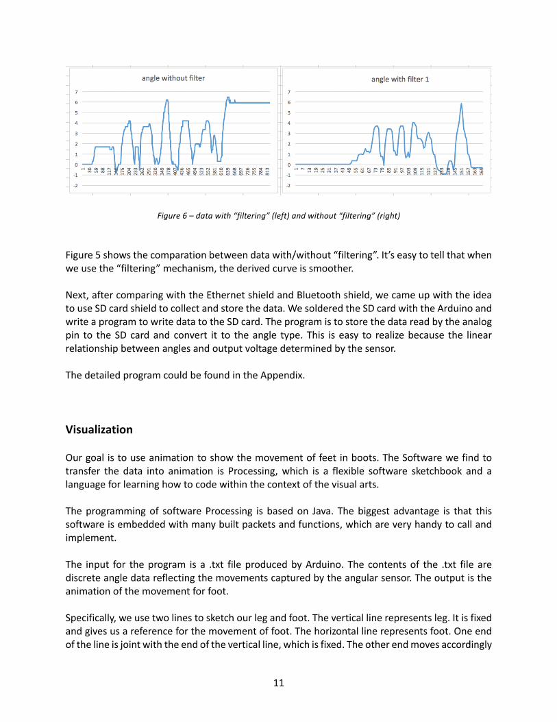
TheinputpowersupplyfortheArduinowechooseis6V,whichispoweredby4batteriesandeachis1.5V.ThenumberofanalogI/Opinsithasis6whichisenoughforourproject.Forthedetailsaboutprogramming,itincludestwoparts.ThefirstpartistolettheArduinoreadthedatafromtheanalogpinandusetheserialmonitortoobservethedata.Thesampleratewesetbeforewas10ms.Butwhenwesteppedintotheoptimizationstage,wechangedthesamplerateto1msandtaketheaverageofevery10readdata.Thisisforthepurposeof“filtering”dataandomittingtheeffectofsomeextremedatacausedbynoise.Eventhoughthesampleratewesetinprogramis1ms,aftertakingtheaverage,the“true”samplerateisstill10ms.
11
Figure6–datawith“filtering”(left)andwithout“filtering”(right)Figure5showsthecomparationbetweendatawith/without“filtering”.It’seasytotellthatwhenweusethe“filtering”mechanism,thederivedcurveissmoother.Next,aftercomparingwiththeEthernetshieldandBluetoothshield,wecameupwiththeideatouseSDcardshieldtocollectandstorethedata.WesolderedtheSDcardwiththeArduinoandwriteaprogramtowritedatatotheSDcard.Theprogramistostorethedatareadbytheanalogpin to theSDcardandconvert it to theangle type.This iseasy to realizebecause the linearrelationshipbetweenanglesandoutputvoltagedeterminedbythesensor.ThedetailedprogramcouldbefoundintheAppendix.VisualizationOurgoalistouseanimationtoshowthemovementoffeetinboots.TheSoftwarewefindtotransfer the data into animation is Processing,which is a flexible software sketchbook and alanguageforlearninghowtocodewithinthecontextofthevisualarts.Theprogrammingof softwareProcessing is basedon Java. Thebiggest advantage is that thissoftwareisembeddedwithmanybuiltpacketsandfunctions,whichareveryhandytocallandimplement.The input for theprogram is a .txt fileproducedbyArduino.The contentsof the .txt file arediscreteangledatareflectingthemovementscapturedbytheangularsensor.Theoutputistheanimationofthemovementforfoot.Specifically,weusetwolinestosketchourlegandfoot.Theverticallinerepresentsleg.Itisfixedandgivesusareferenceforthemovementoffoot.Thehorizontallinerepresentsfoot.Oneendofthelineisjointwiththeendoftheverticalline,whichisfixed.Theotherendmovesaccordingly

12
withrespecttotheinputangles.Alsointhefinalimplementationweusetwosetsofsuchlinesdescribedabovetorepresentthemovementofbarefootandthatoffootinboot.Thesetwosetsoflinesmovesynchronouslytogiveusadirectcomparisonofthedifferencebetweenthetwomovements.
Figure7–TheoutputanimationproducedbyProcessing
Figure7showsascreenshotofdynamicProcessingoutput.Thebiggestdifferencebetweenthemovementofbarefoot(theleftfigure)andthemovementoffootinboot(therightfigure)isthatthefirstonemovesfasterthanthelatter,aswellastherangeofthefirstmovementislargerthanthatofthelatter.Theprogrammingcouldbedividedintothreesteps:
• findthepathandreadintheangledatain.txtfile.• constructtwovectorsandmovethemaccordinglywithrespecttothereaddata.• drawthelinesasshowninFigure5.Theframeisdrawnevery10mswhichcorresponds
tothesamplerateofArduino.(Theactualsamplerateis1ms.Butbecauseofthe“filtering”mechanism,the“true”samplerateisfilteredto10ms)
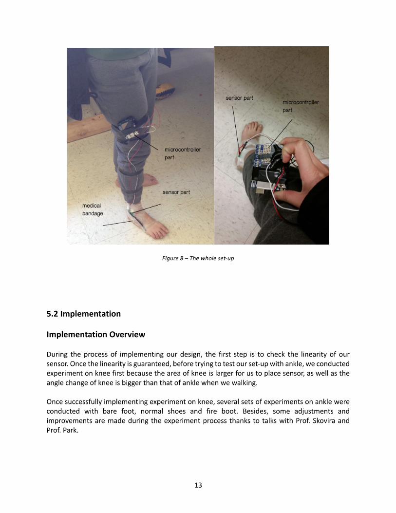
ThedetailedprogramcouldbefoundintheAppendix.TheintegratedsystemPuttingabovediscussiontogether,thewholeset-upisasfollows:Weputthesensoronwherethejointisonourankle.Thesensorisfixedwithmedicalbandage.Microcontrollerisfixedonanotherpartofourbodyandcouldbeonthebootaswell.Thepowersupplyconsistsfour1.5Vbatteriesandcansupply6Vvoltageintotal.Thewholeset-upisshowninFigure8.
13
Figure8–Thewholeset-up
5.2ImplementationImplementationOverviewDuring theprocess of implementingour design, the first step is to check the linearity of oursensor.Oncethelinearityisguaranteed,beforetryingtotestourset-upwithankle,weconductedexperimentonkneefirstbecausetheareaofkneeislargerforustoplacesensor,aswellastheanglechangeofkneeisbiggerthanthatofanklewhenwewalking.Oncesuccessfullyimplementingexperimentonknee,severalsetsofexperimentsonanklewereconducted with bare foot, normal shoes and fire boot. Besides, some adjustments andimprovementsaremadeduring theexperimentprocess thanks to talkswithProf.SkoviraandProf.Park.

14
SensorVerificationAfterreceivingoursensors,thefirststepistodosomeexperimentstocheckthelinearityofthissensor.
Figure9–Linearitycheckwithdrawncircle
Figure10–Rotatingsensortochecklinearity

15
Figure 9 and Figure 10 shows the implementation process of linearity verification. Generallyspeaking,thewaywetookistoconnectthesensorwithpowerandscopecorrectly,fixthesensoronpaperanddrawacirclearoundit.Eachtimewerotatedthesensorsothattheoutputvoltagewouldbechangedby0.2V.Thenwemarkedtheanglechangeonthecircle.
Figure11–linearityverificationgraphgeneratedbyExcelThe expected result should be that all the angles between two marks are equal, which isimpossible.WhenwedrewtheanglesaccordingtothecircleinExcel,whichisshownbyFigure11,it’seasytotellthattheoutputvoltageisproportionaltotherotatedangleeventhoughtherelationshipisnotabsolutelylinearbecauseoferrors.Sothelinearityofthesensorsatisfiesourrequirement.TestonkneeAsmentionedabove,beforeimplementationtestontheankle,westartedtestingourequipmentontheknee.Theimplementationonkneeiseasiercomparedwiththatonankle.Firstly,theareaofkneeislargerforustoplacethesensorandactuator.What’smore,theanglechangeofkneeisbiggerthanthatofanklewhenwearewalking.Soitismeaninglessforustoconducttheexperimentonanklewithoutobtainingexpectedresultsfromexperimentsontheknee.
16
Figure12–Testonknee
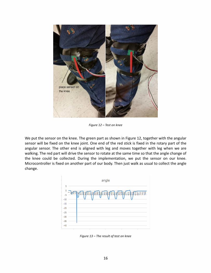
Weputthesensorontheknee.ThegreenpartasshowninFigure12,togetherwiththeangularsensorwillbefixedonthekneejoint.Oneendoftheredstickisfixedintherotarypartoftheangular sensor. The other end is alignedwith leg andmoves togetherwith legwhenwe arewalking.Theredpartwilldrivethesensortorotateatthesametimesothattheanglechangeofthe knee could be collected. During the implementation, we put the sensor on our knee.Microcontrollerisfixedonanotherpartofourbody.Thenjustwalkasusualtocollecttheanglechange.
Figure13–Theresultoftestonknee

17
Figure13showstheresultoftestonknee.It’seasytoconcludethatthemovementofkneeisperiodic.Andtherangeofthemovementisalmost10degrees.FirstattemptonankleOncewegottheexpectedresultfromthetestontheknee,webeganourtestontheankle.Theprocessisverysimilarwiththeprocessforthetestonknee.Weputthesensorontheankle.ThegreenpartasshowninFigure10,togetherwiththeangularsensorwillbefixedontheanklejoint.Oneendoftheredstickisfixedintherotarypartoftheangularsensor.Theotherendisalignedwithoutstepandmovestogetherwithoutstepwhenwearewalking.Theredpartwilldrive the sensor to rotate at the same time so that the angle change of the ankle could becollected.Duringtheimplementation,microcontrollerisfixedontheleg.Thenwewalkedasusualtocollecttheanglechangeofankle.
Figure14–Firstattemptonankle
18
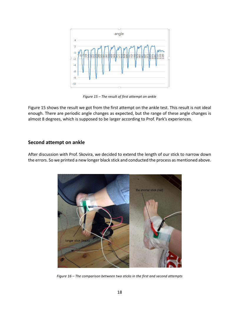
Figure15–TheresultoffirstattemptonankleFigure15showstheresultwegotfromthefirstattemptontheankletest.Thisresultisnotidealenough.Thereareperiodicanglechangesasexpected,buttherangeoftheseanglechangesisalmost8degrees,whichissupposedtobelargeraccordingtoProf.Park’sexperiences.SecondattemptonankleAfterdiscussionwithProf.Skovira,wedecidedtoextendthelengthofoursticktonarrowdowntheerrors.Soweprintedanewlongerblackstickandconductedtheprocessasmentionedabove.
Figure16–Thecomparisonbetweentwosticksinthefirstandsecondattempts
19
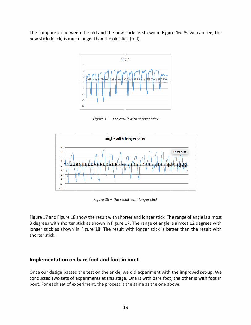
ThecomparisonbetweentheoldandthenewsticksisshowninFigure16.Aswecansee,thenewstick(black)ismuchlongerthantheoldstick(red).
Figure17–Theresultwithshorterstick
Figure18–TheresultwithlongerstickFigure17andFigure18showtheresultwithshorterandlongerstick.Therangeofangleisalmost8degreeswithshorterstickasshowninFigure17.Therangeofangleisalmost12degreeswithlonger stick as shown in Figure18. The resultwith longer stick is better than the resultwithshorterstick.ImplementationonbarefootandfootinbootOnceourdesignpassedthetestontheankle,wedidexperimentwiththeimprovedset-up.Weconductedtwosetsofexperimentsatthisstage.Oneiswithbarefoot,theotheriswithfootinboot.Foreachsetofexperiment,theprocessisthesameastheoneabove.

20
Figure19–Experimentsonbarefootandfootinboot
Figure20–Theresultofexperimentsonbarefootandfootinboot
Figure19showstheprocessduringtheexperimentsonbare footand foot inboot.Figure20showstheresult.Fromthecontradictofthesetwopictures,wecanseethatwhenwearingthebootsornotwillbringbigdifferencetothefrequencyofmovementandtheactionsthatthefeettake.DetailsaboutthedifferencearediscussedinResultpart.

21
Implementationonbarefoot,footinrequiredbootsandrunningshoesOurfinalexperimentisaskedbyProf.Park.Becausehewantstoknowthemovementdifferenceamong bare foot, foot in required boots and running shoes, we conducted several sets ofexperimentswithout/withdifferentkindsofshoes.Foreachsetofexperiment,theprocessisthesameastheoneabove.Butbecauseofthelimitationoftime,theseexperimentshaven’tbeenfinishedyet.
6.comparisonwithoriginaldesign
Ouroriginalgoaloftheprojectistodesignasystemwhichcouldcapturethemovementofthefootandthenstore thedata intodatabase for futureanalysisuseandbuildanimationof themovement of foot based on the data the system collected. The system could capture themovementofdifferentpartofthefootsothatthemovementcouldbeshownina3-Danimation.Weexpecttoletthetestertowearourgearandwalktocollectdata.Thedatawillbecollectedwhen the tester is in following situations: barefoot,wearing ordinary shoes andwearing thecertainboots.Andwecouldcomparethemovementofthesametesterwhenwearingdifferentshoes.Andthesystemthatwebuildnowiscapableofcapturethemovementoftheankleofthefootandtheresultwillintextform.Wethenshowthe2-Danimationoftheanklemovementusingthesedata.Wedidn’tbuildadatabaseforstoringthedataeither.Nowwehavedoneseveraltestsofthesystem.Wefirstletthetesterwearthegearandwalkinbarefootandcollectthedata.Andthenthetesterisaskedtowearthegearandputhisfootinhisshoestogetthedata.Andheisasked to wear two different kinds of boots when wearing the gear as the third and forthexperiment.We then put the collected data into Excel and then use line chart to show themovementof thefootanddoanalysisbasedonthe linechart.Wealsouseasoftwarecalledprocessing to show the animation of the ankle. Because our data collected is the change ofrelativeanglesofthefootandtheleg,thusweusetwolinestorepresentlegandthefootandbuildtheanimationbasedthedata.Our system is different from our original goal from three parts: first, we didn’t capture themovementofthewholefoot, instead,wecapturethemovementoftheankleonly.Wedidn’tachieveouroriginalgoalbecausetogettheinformationforthewholefoot,weneedtotestthemovementofdifferentpartsofthefootandneedtoanalysishoweachdataisrelatedtoeachotheranduse thesedata tobuild theanimation,which is toochallenging forus.The seconddifferenceisthatwedidn’tbuildadatabase,instead,wekeepthedataintextform.Wedothischangebecauserightnowwedon’tneedtodocomplicatedqueries,butwemayneedtousedatabaseinthefuture.Thelastdifferenceisthatwebuild2-Danimationinsteadof3-Danimation.Wemakethischangebecauseweonlymeasurethemovementoftheanklethus2-Danimationisclearlyenoughtoshowhowtheanklemoveswhenwearingdifferentkindofshoes.

22
7.FinalResultThesampleofrawdatacollectedisshowninAppendixC.Weusethesedatatogenerateourlinechart,whichcouldshowthedifferencebetweenthemovementoffootwhenwearingthebootandnot.
Figure21–Themovementoffootwhenwearingtheboot
Figure22–ThemovementoffootwithoutbootFromthecontradictofthesetwopictures,wecanseethatwhenwearingtheboots,therangeofmovementissmallerthanwithbarefoot.Besides,thefrequencyofmovementwhenwearingbootsislowerthanthefrequencyofmovementwithbarefoot.Thetwodifferencemaybecausedbytheweightofboot,whichimpedesthenormalmovementofsubject.
-2
-1
0
1
2
3
1 65 129
193
257
321
385
449
513
577
641
705
769
833
897
961
1025
1089
1153
1217
1281
1345
1409
1473
1537
1601
1665
1729
1793
1857
1921
1985
2049
2113
2177
anglewithboot
-12-10-8-6-4-20246
1 66 131
196
261
326
391
456
521
586
651
716
781
846
911
976
1041
1106
1171
1236
1301
1366
1431
1496
1561
1626
1691
1756
1821
1886
1951
2016
2081
2146
anglewithoutboot

23
8.ChallengesWhendesigningthesystem,wehaveencounteredseveralchallenges.Choosingsuitablesensorisessentialtoourprojectandisnotaneasytasksincethepopularsolutionsavailableallfailstomeetourdemandasdiscussedinpart(4).Andwecouldonlytrytosearchthesensorswewantanddiscusswhetherthesolutioncouldsucceedornot.Andfinallywecametotheangularsensorandfounditsuitableforoursystem.Wetrytouseawoodenstickaspartofoursystem.Andthenwediscoverthatthewoodenstickistoofragileandeasytobreak.Toovercomethisproblem,wechoosetouse3Dprintertobuildanewstick.Becausewedon’tknowhowtousethe3Dprinterandthuswecouldonlystartfromscratchanddosomeexperimentstomastertheskillsthatweneedtobuildthestickwewantusingthe3Dprinter.Weneedtofindawaytostoreourdatawhenfinishingcollecting.WecometothesolutionusingSDcardbecauseitiseasytostorethedatabutamoresuitablemethodwouldbeusingthedatabase.9.ConclusionThegoalofthisprojectistotocapturethemotionoffootwhenfirefightersarewearingbootsSuchamotioncapturesystemissuccessfullyconstructedandfoundtomeetdesignspecifications.Angular sensor is chosenas themostdirectandsuitableway to realize this system.One-unitdesign,whichincludestwoplasticbarsandoneflexibleanglesensor,isalignedwithbodilyaxissothatthemovementofbodywoulddrivetheangularsensortochangeatthesametime.Oncethesignalfromsensorsarecollected,anArduinoisusedtocollectdata,storethemlocallywithSDcardanduploadthemtoPC.Finally,rawdatawouldbedisplayedandanimatedbysoftwareProcessing.Therefore,themaingoalforthisprojectisaccomplished.Analyzingthedatawecollected,wecouldseethatwhenwearingtheboots,frequencyofmovementishigherthanbarefootandwecanseethatthechangeintherelativeanglesismuchsmallerwhenwearingtheboot.Thus,wecouldcometotheconclusionthatwearingthebootswillrestricttheanklemovement.

24
10.FutureWorkNowthebiggestproblemforoursystemisthatwhenwearewalking,relevantshiftingbetweenthebodypartandthesensormayhappen,resultinginobviouserrors.Besides,tomakesurethestickcouldbebentalittlebittofitthesurfaceofourfoot,flexibilitymustbeguaranteedtosomedegree.However,thiswillcausetheanglechangenotasaccurateasitissupposedtobe,sincethestickmaybendwhenwearewalking.Theseproblemsmustbesolvedinthefutureworkinthefirstplace.Fortheoptimization,nowthesystemcouldonlysupportdatacollectedfromoneboot.Itcouldbeimprovedtosupportcollectingdatafromseveralbootssimultaneously.Adatabasecouldbeaddedtosupportstoringandqueryingforspecificdata.Alsoimprovingthewayofdatatransfercouldbeavaluablechangeinthefuture.NowthedataistransportedbySDcard.ItcouldbeoptimizedtouseWIFIorBluetoothtotransferthecollecteddata.Forfielduse,weareexpectingtoexpandthesystemtocommunicatetoBluetoothenabledserverinfirehouse.Individualdataforeachfirefighterwouldthenbesavedinthedatabaseforlateranalysis.11.AcknowledgementWecan’tfinishthisprojectwithoutmyadvisor:Dr.JosephSkoviraandDr.HuijuPark.Thanksfortheirpatientguidance.Thanksfortheiradvicewhenwecan’tfindawaytodesign.

25
References:1.Arduinodatasheetfromofficialwebpage;Availablefromhttps://www.arduino.cc/en/Main/ArduinoBoardUno2.ArduinoLanguagereference;Availablefromhttps://www.arduino.cc/en/Reference/HomePage3.RotaryPositionSensorSV03Series;Availablefromhttp://www.murata.com/zh-cn/products/sensor/rotaryposition?intcid5=com_xxx_xxx_cmn_bc_xxx#header_0_RegionLanguagePanel4.Processingsoftwarereference;Availablefromhttps://processing.org/reference/5.DocumentationforcomparingthederivedanglesGaitAnalysis:NormalAndPathologicalFunction/Edition1byJacquelinPerry,BillSchoneberger

26
AppendixA:CodeforArduino
ModuleName:SensorDatacollect
Date:2015.11.20
Developer:LiweiHan
Description:ThismodulecodemainlytakesresponsibilityofcollectingthedatafromsensorandstoringthemontheSDcardin.txtformat.
#include <SD.h> int CS_pin = 10; // cs pin for sd card shield int sensorPin = 2; // sensor read-in analog I/O pin float value = 0.00; // value from sensor float temp = 0.00; // transferred volatage value float angle1 = 0.00; // transferred angle value every millisecond float angle = 0.00; // summed value of every 10 angle1 value float ini_value = 0.00; // store initial sensor value int count = 0.00; // counter for filter function void setup() { Serial.begin(9600); // set data rate 9600 bits per second Serial.println("Initializing Card"); pinMode(CS_pin, OUTPUT); // I/O pin 10 : output if(!SD.begin(CS_pin)) // check SD shield state { Serial.println("Card Failed"); return; } Serial.println("Card Ready"); String title = "angle"; // title in the output file ini_value = analogRead(sensorPin); // record initial position’s value // create test.txt in SD card File dataFile = SD.open("test.txt", FILE_WRITE); if(dataFile) { dataFile.println(title); // write title to the file dataFile.close(); } }

27
void loop() { value = analogRead(sensorPin); // value from sensor temp = (value-ini_value) / 214.6; // transfer to the voltage value count = count + 1; angle1 = temp * 60; // transfer to the angle value angle = angle + angle1; // sum angle1 value (used by filter) // average filter function if (count > 10) { count = 0.00; angle = angle / 10; File dataFile = SD.open("test.txt", FILE_WRITE); if(dataFile) { dataFile.println(angle); // write filtered data to the file dataFile.close(); Serial.println(angle); angle = 0.00; } } delay(1); // log the sensors every millisecond }

28
AppendixB:Codeforprocessing
ModuleName:ProcessingDataDisplay
Date:2016.04.15
Developer:DiHuang
Description:ThismodulecodemainlytakesresponsibilityofdisplayingthedatacollectedandprocessedbyArduinoUnointheformatof.txt.
// declare vector used to draw lines PVector center1; PVector fix1; PVector move1; PVector center2; PVector fix2; PVector move2;
// declare buffer reader BufferedReader reader1; BufferedReader reader2;
// declare lines to draw String line1; String line2;
// declare angles float angle1; float angle2;
void setup(){ size(640, 640); // set up the size of the screen // set up the path for readers reader1 = createReader("/Users/constance2587/Desktop/project/progressupdate/processing/bare.txt"); reader2 = createReader("/Users/constance2587/Desktop/project/progressupdate/processing/boot.txt"); // set up the start point of two lines center1 = new PVector(width / 4, height / 2); center2 = new PVector(width * 3 / 4, height / 2); frameRate(30); // set up the frame frequency }

29
void draw(){ background(0); // set up the background color try { // read data from .txt line1 = reader1.readLine(); line2 = reader2.readLine(); } catch (IOException e) { e.printStackTrace(); line1 = null; line2 = null; } //once lines in .txt are null, stop reading if (line1 == null || line2 == null) { noLoop(); } else { //interpret the read data to angles String[] pieces1 = split(line1, TAB); float angle1 = float(pieces1[0]); String[] pieces2 = split(line2, TAB); float angle2 = float(pieces2[0]); // calculate the end point of two sets of lines fix1 = new PVector(0, 200); fix1.add(center1); move1 = new PVector(80, 0); move1.rotate(radians(angle1)); move1.add(fix1); fix2 = new PVector(0, 200); fix2.add(center2); move2 = new PVector(80, 0); move2.rotate(radians(angle2)); move2.add(fix2); //set up the propriety of the drawn lines stroke(255);
strokeWeight(4);
//draw the lines line(center1.x, center1.y, fix1.x, fix1.y); line(fix1.x, fix1.y, move1.x, move1.y); line(center2.x, center2.y, fix2.x, fix2.y); line(fix2.x, fix2.y, move2.x, move2.y); }

30
AppendixC:sampleofrawdata
angle angle0.62 00.92 00.92 -0.621.23 -0.921.23 -0.871.23 -0.891.23 -0.921.23 -0.891.23 -0.891.23 -0.921.23 -0.921.23 -0.920.78 -0.920.34 -0.67
0 -0.62-0.53 -0.62-1.31 -0.62-1.82 -0.62-1.85 -0.62-2.07 -0.62-2.35 -0.62-2.46 -0.62-2.77 -0.62-2.8 -0.62
-3.08 -0.62-3.08 -0.62-3.38 -0.62-3.38 -0.62-3.69 -0.39-3.94 -0.31
-4 -0.17-4 0

31
AppendixD:modelingfor3Dprinter
ModuleName:Modelingfor3Dprinter
Date:2016.02.10
Developer:DiHuang
Description:Thissolidfigureisusedforbuildingthemodelfor3Dprintertoprint.ItisdrawnwithAutoCAD.