Embed Size (px)
Citation preview

C H A P T E R 2
E X P E R I M E N T A L
2 . 1 PROCEDURE
Following raw materials ware used for the present
investigation.
2.1.1 Iron powder
High compressibi l i ty sponge i ron powder, grade NC
100.24, obtained from Hdganas AB, Sweden, was se lected as
base mater ia l . Charac te r i s t i c s of t h i s powder are :
Carbon content
Si0 2
IL> l o s s
Apparent densi ty
Flow r a t e
(Hall flow meter)
Compressibil i ty
P a r t i c l e s i ze
0.01 %
0.22 %
0.20 %
2.4Mg/m3
31 secs/50 gms.
6 .k Mg/m5 a t 420 MPa
+100 mesh . . . 0.5 % approx.
-325 mesh . . . 21.5 % approx.
2 .1 .2 P-contalaing sponge i ron powder
PNC30, PNC45 and PNC60 supplied by Hoganas AB,
(18)

19
Sweden were used for 0 .3 , 0.45 and 0.6 pe t , P-containing
i ron powder, respec t ive ly . These powders are based on
NC100.24 with admixed ferrophosphorus (Fe,P) containing
15.6 c/> phosphorus. Charac te r i s t i c s of these powders are
Carbon content
S i0 2
R, loss
Apparent densi ty
Flow ra t e
(Hall flow meter)
Compressibili ty
P a r t i c l e s i ze
0.01 %
0.16 %
0.20 %
2.6 Mg/m3
31 secs/50 gms.
6.4 Mg/m3 a t 420 MPa
•(•100 mesh . . . 1 % maximum
-325 mesh . . . 20 %
P-containing atomized i ron powder
PA8C30 and PASC80 powders obtained from Hftganas AB,
Sweden were used for 0.3 and 0.3 % P-containing i ron r e s
pec t ive ly . These powders are based on very pure and super
compress ibi l i ty i ron powder grade ASC100.29. Charac te r i s
t i c s of these powders are :
Carbon content 0.01 %
Hg los s 0.1 %
Apparent densi ty 3.0 Mg/m3
Flow rate
(Hall flow meter)
Compressibility
Particle size
27 secs/50 gms.
6.70 Mg/m3 at 420 MPa
and 7.00 Mg/m3 at 600 MPa
+65 mesh 0 %
+100 mesh ... 10 % maximum
-325 mesh ... 20 %
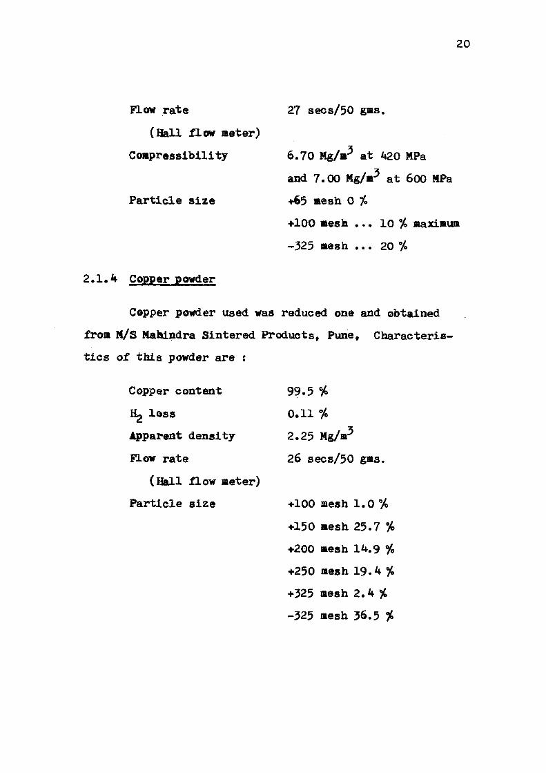
2.1.4 Copper powder
Copper powder used was reduced one and obtained
from M/S Mahindra Sintered Products, Pune, Characteris
tics of this powder are :
Copper content
Hp loss
Apparent density
Flow rate
(Hall flow meter)
Particle size
99.5 %
0.11 %
2.25 Mg/m3
26 secs/50 gms.
+100 mesh 1.0 %
+150 mesh 25.7 %
+200 mesh 14.9 %
+250 mesh 19.4 %
+325 mesh 2.4 %
-325 mesh 36.5 %

21
2 .1 .5 MCM and MVM powder
MCM and MVM are t r a n s i t i o n metal carbide master
a l l o y s . MCM contains manganese, chromium and molybdenum
while MVM contains Vanadium ins tead of chromium and ca r
bon and i ron as balance. These powders of average p a r t i c l e
s i ze 5 urn FSSS were obtained from S in t e r metallwerk, GmbH,
Krebsoge, W.G. and have the following composition:
% Mn Cr V Mo Cu C Si
MCM 20 20 - 20 0.22 7 0.35
MVM 20 20 20 0.22 5 0.40
2 .1 .6 Molybdenum powder
Molybdenum powder used was obtained from meta l l
werk, Plansee, Austr ia of p a r t i c l e s i ze 4-6 urn which was
measured on Fischer subsieve s i z e r .
2 .1 .7 Nickel powder
Nickel powder used was type 255* obtained from
INCO Europe Ltd., London, U.K., the characteristics of
this powder are as follows :
Chemical composition
Ni Balance

22
C 0.2 %
Fe 0.005 %
Co 0.0003 %
N 0.0002 7.
0 0.07 %
S 0.0002 %
Other t r a c e elements < 0.001 %
Apparent densi ty measured by Scott-Volumeter - 0.50-0.65
Mg/m5.
Typical specif ic surface area m /g - 0.7
Average p a r t i c l e s i ze um = 2 .2-2 .8 FSSS
2 .1 .8 Graphite
Graphite powder grade UF^ of average particle size
4 pi FSSS was obtained from Sintermetallwerk, Krebsoge, W.G.
2.2 PRBMIX PREPARATION
In sponge iron powder, phosphorus content was
varied as 0, 0.30, 0.45 and 0.6 wt. °/>. Alloying additions,
Cu and MCM were varied at an interval of 1 wt. % and upto
4 wt. %, In case of ternary premixes, i.e. PNC60-Ni-Cu,
PNC45-Mo-Cu or PNC60-Mo-Cu and PNC60-MCM-Cu, copper content
was 1 and 4 wt. %.

23
In case of super compressibil i ty atomized i ron
powder, the phosphorus content was var ied as 0, 0.30 and
0.8 wt. % with 0.3 or 0.6 % carbon (Actually, the graphi te
addi t ion for C was 0.5 and 1.0 % t o compensate for l o s s
during s in te r ing which was evaluated a f t e r preliminary
experiments), and 1 or 2 % each of Cu, Ni, Mo, MCM or
MVM, Various premixes were prepared by mannual mixing
for 1 hour using acetone as medium. No lub r i can t was added
during mixing.
2 .3 COMPACTION
Green compacts of the dimension 5 m m x 5 m m x 2 0 m m
were made in a s ing le act ion compression machine a t a
pressure of 600 MPa. The die made of special K s t e e l ,
cleaned with acetone, lubr ica ted with zinc s t e a r a t e and
f i l l e d with powder premix, was subjected t o the required
load a t an approximate r a t e of loading of 1000 kg/minute.
MPIF (Metal Powders Indus t r i e s Federation) standard t e n s i l e
t e s t ba r s , the d e t a i l s of which a re given in Fig. 2 .1 and
having a thickness of approximately 5«7 mm were made on
Bussmann Demag hydraulic press of 200 tons capaci ty a t 691
MPa pressure . The d ie wall was lubr ica ted with kenulube
11 . Green densi ty of the compacts were determined by dimen
sional measurement and i s summarized in t ab l e I I I . 3 . 1 .

U593
II il 3.187 • .001 3 .529 " i . 0 0 l " o
< Z o o
F ig . 2-1 MPIF tens i le test p i e c e ; green d i m e n s i o n , when in the d i e -

24
2.4 SINTERING
2.4.1 Hydrogen atmosphere sintering
Green pellets were sintered in a globar tubular
furnace under dry hydrogen atmosphere at 1120°C for 30
min. The furnace tube had ID of 6.26 cms. and capable
of attaining a maximum temperature of 1300°C with a
control of ± 10°C over a length of 1G cms. at the centre.
The temperature profile of the furnace is shown in Fig.
2.2. The rate of heating to sintering temperature was
7 K/min. The rate of cooling from sintering temperature
was 13 K/min. in case of Fe-P-Cu compacts while in other,
it was 16 K/min.
2.4.2 Dissociated ammonia atmosphere sintering
MPIF tensile test bars made from PASC powders were
sintered in pusher type Industrial furnace at 1120°C for
30 minutes in cracked ammonia atmosphere (dew point 240 K)
of M/S Mahindra Sintered Products Ltd., Pune.
2.5 SINTERING PARAMETERS
2.5.1 Linear dimensional change
Linear dimensional change of MPIF tensile test
bars was calculated by measuring the difference between

1200 -
10 2 0 30
Distance from one e n d , Cm
Fig. 2.2 TEMPERATURE PROFILE OF THE SINTERING FURNACE
AT 1120 C

25
sintered and green length as follows :
Pet. Linear dimensional change »
Sintered length - Green length x 100
Green length
In case of cylindrical compacts, radial dimensional change
was also determined as above. Shrinkage ratio was calcu
lated whereever it was possible as follows :
Radial dimensional change Shrinkage ratio •
Axial dimensional change
Volumetric shrinkage or growth was also derived as follows:
where ^s 0/ is volumetric change, V and V\ are sintered v s g
and green volumes respectively.
2.5.2 Sintered density
Sintered density was calculated from the mass of
the samples and dimensional measurements of the MPIF
tensile test bars immediately after sintering. The mass
of the compacts were determined on an electrical balance
of capacity 100 gms. The balance had a measurement

26
accuracy of £0.0005 gas. Sintered density of few compacts
were also measured by Archmedis principle by first dipping
in silicone oil to close open porosity and then usual
measurement of mass of samples in air and water. The
variation in sintered densities between these two methods
were not more than 2 %.
2.5.3 Densification parameter
Densification parameter (AD) was calculated from
the formula :
Sintered density - Green density AD »
Theoretical density - Green density
Theoretical density of iron was taken as 7.86 Mg/m .
Theoretical density of each composition was calculated from
rule of mixture taking the theoretical density of the
various elements at room temperature as follows :
Density Phosphorus Graphite Copper Mlokel
Mg/m3 1.82 2.25 8.92 8.91
Molybdenum MCM MVM
10.2 7.4 7.4
Theoretical density of the various premixes for
evaluation of sintered properties are shown in table 2.1

27
• a o >>
«> (Q
O « •0 5
w 3 «
ft
9
CO
>
o
+> «J C «
7J
o
J
CM
H
H
3£ <B 09
&g
o H
3
to -4-•4- tn eo co
0) En
io in <r tO 00
'D - 4 CO
VO m 00
m cr> CM CO H CO ON
3 o H 1
'D • *
3 O CM 1
^ -4
3 o K> 1
•£> •4-y o o o K 0U CU S
CM fO VO - 4 K> CO SO 00
3
3 1
J -O
£
3 O H d> VO CJ
£
3 O CM
1 O
. vO
£i 04
3 O to 1
o vO O
£
3
X 4 vO C)
£
-4
8 H
CO CO
o to O Z 04
5> o 2 a,
o vO O z a,
3 o H
1 O z
3 CJ CM
1 O Z
3 CJ t o 1
o z
3
I O z
CM C* 00
S¥ O ON
CM m 00
ro -4-$ So
3 O H 1
O t o o z 04
3 o CM 1
O IO o z cu
3 o t o
<i t o o z 04
lO to
5 g £ * A d> A <J> to to to to y £ S z 3
Oi O4 O4
00
3
I o to 0
3 c •H -P §

28
1 o >»
•H+>
O 0)
a *
o H
•3 O S •H-P • P T H 0) 09
O 0)
O H 5|
CO -Jt &\ <t & & c! ri eo oo co oo
8 § B 8 a ft a 5
i i i i
£ £ 04 flu
b O 4 s •4; t : g> H oo GO oo <^
• • • • C - C - t ^ C"-
o o o o 3 ft K'5 o o o cS ^O <0 V© vO
u y y. o 5F S5 • 3 s 8 s
o< 04 Q4 04
f-c\j 00
• t*«
§ s H 1 O & y £
<f H 00
• t>-
K A V& O
£
O H co • ^
X
(^
d, vO U s-
8 eo • t -
8 3 6 v© 0
flu
0 -
$ •
f-
lCu
A s 1
-* 0
E
t--ON 00
• t -
3
h s 1
in •4" O E
0 o» 00
• 1^
ICu
0
R 1
-* O
E
CM CV1 0>
• f-
3 3 A ft 1
-*• 0
E
• • •
ued
Contin
m i-t vg CM tf\ m •« 4 00 00 CO 00
t - ITS 00 m n A N M 00 CO 00 00
8 5" 5 5 S IS-'* 5 A 1 1 .1 as z z 25
8 8 8 8 S ft & 5 <4 d> d> 6 fT\ fC\ ff\ *C\ P O O O E § E
E

29
r-i CS O >» •H-P -P-H ffl 00 k C O D
5 &
g O
H
CM
0) H
2
-P-H
O 9>
&
v© Op
oo co i n
GO
t>-8
vfl
CO
CO o cr>
CM
g -* ON 80
5
\o tt
E*-
3 u H 1
§ 5
1 O V© O 2 CU
3 o H 1
O
5 d> V0 o z &
3 o H 1 zd 2 CM
d> vO y ? cu
3 5
1 •H Z CM
d> 10 O 2 04
3 o H 1 •H 5 1 O VO
a z 04
3 5? i
•H f d> vo Q Z 04
o CO o to S5
s H 1
O m
• O 80-
u 03
cu
8 CM 1
O K> •
o
80-
o 3 04
3 o H 1
O vO
• o
80-
o CO
< Oi
3 CM
1 o vo
• o
80-
o § cu
t o H <T>
CO CM C*
O VO 0>
m CM oo
f -IA GO
^ -* GO
- * CM CO
i n K\ GO
m i n o\
ts o 00
3 O H 0
0-2M
V0 o £
3 5
1 O
d> v>© O £ 04
3 o H A * d> VO O SP 04
3 5 o
5 d> vo o 2 04
3 O
n1
§
0-2M
KO o z 04
3 3
1
§
0-2M
vo y S5 OL.
o
o 3 04
3 O H
d> fn
• o 6 O
3 04
3 O CM 1
o rn •
30-0
u CO «< a<
3 o H 1
O VO
•
30-0
o to < cu
3 O CM 1
o •
30-0
o co <! 04
0) 3 C •H •P O O

30
3 o •» •H-P
<D n
O 4)
o r-»
ON C--
• I S
•H
H 1
O t o
• O
6 00 o CO <! 04
s 00
• t^-
•H
CM 1
O IO
• o 6 00 o 3 0 ,
V0 C--
• c*-
•H
1
s •
o 6 00 c_> 9 04
ts •
c*-
•H 2 CM 1
o <J3 •
o <i 00 o s 04
6 00
• C--
o s 1
o to •
o 6 00 o 3 04
o IO oo
• c
o s
1 o t o
• o 6 CO o 3 a,
£ I S
• c -
o £ H
1
8 •
o d> 00 u CO << a*
802
• t*-
o £ CM
1 o vD
• O
6 00 u 3 04
CO c»-
• t*~
s £
1 u t o
• o 6 00 o CO 5< Du
- * t -t*-
• c»
§ £ CM 1
O fO
• o
1
o oo u co 04
H
tr-•
C--
g 5 1 O &
• o 6 00 o CO
0<
5 t«-
• C--
g 8 1 o *£>
• o 6 00 o 3 04
•d 0) 3 a •H
§
•3
u n o «
H
CM CO
IO to to trv 0\ ON
fc CO
ts IO 00
H
00 8 00
CM
00 s oo
cS 00
00 I S t*-
•H
H 1
U fO
• o ci> tO O
9 04
•H
CM 1
o tO •
o d> IO o
3 o,
•H
H 1
O v0
• o 1
o t o o
3 04
•H
CM 1
O \o
9
O
i t o o
3 04
o
s 1
u t o •
o 1
o fO o co 04
o s
1 o IO
• o 1
o fO o
3 04
o
5 1
CJ V0
• o 1
o IO O
% 04
o £ CM 1
O VO
• o 6 tO O
% 04
£ o B 1
O tO
• O
<4 t o o % 04
5 R
1 CJ t o
• o
30-
u 3 04
8 £ H 1
O vO
• o ci t o o CO << 04
g 8
1 o vO
« o 1
o t o o 9 a.

31
•3 o >, •P -H 0) W h C O «
•a 5
H
3
•d
•H +» a o o
H
CM
CD H 45 CO
O > , •H+> - P - H 4) 00
O 0)
EH
H
T o
• o A CO o
PAS
1 o KV • o 6 00 o
PAS
H 1
8 •
o
80-
o
CM 1
8 •
o A CO o
PAS
8 8 0> VO 00 C « -
«0 «0 N S • •
1 u to
• o 1
o ro O
3 CU
CM 1
o K> •
O
ci to o 23 OU
H 1
O U>
• o A KN O CO
< cu
CM 1
o V0 •
o d, K> o CO
< cm

32
2.6 STEAM TREATMENT EXPERIMENTS
After determining sintered density from weight
and dimensional measurements and Vickers hardness deter
mination at a load of 5 or 10 kg, 3 mm thick slices were
cut and ground with silicon carbide paper of grit size
180 and 320. The slices were cleaned with trichloro
ethylene and acetone and weighed on a microbalance having
an accuracy of ± 0.0005 gm. They were then put in a pre
viously weighed silica boat and inserted into Nichrome
wound tubular furnace having temperature cpntrol of +, 10°C.
Temperature profile of the furnace is showia in Fig. 2.3-
Steam is generated in a retort and preheated in a heated
copper coil to the approximate treatment temperature. The
steam was then passed at atmospheric pressure through the
tube furnace and finally vented to the atmosphere. Speci
mens were introduced into the furnace tube with steam
already flowing and with the furnace at thfc temperature.
Coldest part of furnace charge must be at a tempe
rature greater than 100°C before steam is admitted to the
treatment furnace, otherwise hydroxide of iron is formed
which subsequently changes to red rust according to the
reaction.
2Fe(0H)3 - Fe203 + 3H20

500
400
o
e a.
300
200
100
0 to 20 30 40 50
Distance f rom one e-nd ,Cm
Fig. 2.3 TEMPERATURE PROFILE OF TUBULAR FURNACE AT 500C

33
If air is present in the furnace, Fe2°3 m a v form.
During short time of about 30 or 50 seconds, there is
little chance of air entering into the furnace since the
furnace tube is at positive steam pressure.
For PNC compacts the treatment was carried out at
500°C for times varying between 5 to 120 mins. and for
PASC compacts the treatment was carried out at 450, 500,
527, 550 and 600°C for times of 45, 60, 90, and 120 minutes.
Specimens after steam treatment were weighed and
dimensions were measured. The area of steam oxidised
surface Ag was calculated as follows :
A„ - 2(1 x b • b x t • 1 x t)
where 1 is length, b the breadth and t thickness of oxi
dized slices. Weight gain or loss per unit oxidized area
was calculated and weight gain vs. treatment time was
plotted.
2.7 STRUCTURAL STUDIES
2.7.1 Optical microscopy
Oxidized sintered specimens are among the most
difficult ones to prepare for metallographic examination.
The oxide skin should be retained. They were mounted in

34
Araldite and ground on SiC paper of grit sizes 180, 320,
400, 500 and 600 um. They were then polished on CENSICO
single disc polishing machine using short napped sylvet or
velvet cloth to avoid relief. The machine had a relatively
low speed of 500 rpm. Polishing was done Using 1 micron
alumina powder suspension in distilled water. Preparation
of the specimen was found difficult. Some times free
copper occasionally present in sintered and steam treated
alleys smeared over the surface and frequently oxide layer
was broken up and smeared and embeded in araldite which
shall be evident in third chapter.
Dilute solution of nitric acid in alcohol was used
for etching of the polished specimens.
2.7.2 Scanning electron microscopy
Scanning electron microscopy studies were carried
out on Cambridge Stereoscan Electron Microscope for which
the facilities of Metallurgical Engg. Department of
Banaras Hindu university, Varanasi were used, and Jeol
model JSM-35C for which the facilities of National Bota
nical Research Institute, Lucknow were used. Scanning
electron picture of fractured surfaces was taken on Philips
<Videoscan model PSCM 500 Electron Microscope with a tilt

35
angle of 33.50 a t 30 KVA, for which the f a c i l i t i e s of
RSIC, Bose I n s t i t u t e Calcut ta , were used,
2.8 HARDNESS MEASUREMENTS
Hardness of the steam treated specimens were
determined on Vickers hardness testing machine at a load
of 10 kg. The scatter in hardness reading was + 15 HV10.
Each value is an average of at least six readings.
2.8.1 Mlcrohardness determination
Microhardness of oxide was determined on Buehler
Mlcrohardness tester at a load of 100 gms. Visible pores
and unoxidized area were avoided as far as possible. The
indentor impressions at lower load were sometimes obscure
probably because of pore and/or matrix area being covered
by the indentor. In such cases hardness readings were
discarded and fresh readings were taken. Each micro-
hardness value is an average of at least four readings.
2.9 TENSILE TEST
Tensile testing was done on an Instron machine
Model 1195» with a chart speed of 10 mm/min., cross head
speed of 0.5 mm/min. and full scale of load 2000 kg for
which the facilities of Advance Centre for Material Science,

36
I . I . T . Kanpur were used.
2.10 X-RAY STUDIES
X-ray d i f f rac t ion s tudies of oxidized samples were
ca r r i ed ©ut for which the f a c i l i t i e s of Advance Centre
for Material Science, I . I . T . Kanpur were used.