Embed Size (px)
Citation preview

Level and interface measurement in liquids
Application
• Rod, rope or coax probe• Process connection: Starting 3/4" thread, flange or process connections for hygiene
requirements (Tri-Clamp, 11851)• Temperature: –196 to +450 °C (–320 to +842 °F)• Pressure: –1 to +400 bar (–14.5 to +5 800 psi)• Maximum measuring range: Rod 10 m (33 ft); rope 45 m (148 ft); coax 6 m (20 ft)• Accuracy: ±2 mm (±0.08 in)• International explosion protection certificates; WHG; marine approval; steam
boiler approval; EN10204-3.1• Linearity protocol (3-point, 5-point)
Your benefits
• Reliable measurement even for changing product and process conditions• HistoROM data management for easy commissioning, maintenance and
diagnostics• Highest reliability due to Multi-Echo Tracking• Hardware and software developed according to IEC 61508 (up to SIL3)• Seamless integration into control or asset management systems• Intuitive user interface in national languages• Easy proof test for SIL and WHG
Products Solutions Services
Technical InformationLevelflex FMP51, FMP52,FMP54Guided wave radar
TI01001F/00/EN/20.1671320798

Levelflex FMP51, FMP52, FMP54
2 Endress+Hauser
Table of contents
Important document information . . . . . . . . . . . . . . . 4Symbols . . . . . . . . . . . . . . . . . . . . . . . . . . . . . . . . . . . . 4
Function and system design . . . . . . . . . . . . . . . . . . . 6Measuring principle . . . . . . . . . . . . . . . . . . . . . . . . . . . . 6Measuring system . . . . . . . . . . . . . . . . . . . . . . . . . . . . 10
Input . . . . . . . . . . . . . . . . . . . . . . . . . . . . . . . . . . . . 12Measured variable . . . . . . . . . . . . . . . . . . . . . . . . . . . . 12Measuring range . . . . . . . . . . . . . . . . . . . . . . . . . . . . . 12Blocking distance . . . . . . . . . . . . . . . . . . . . . . . . . . . . 14Measuring frequency spectrum . . . . . . . . . . . . . . . . . . . 14
Output . . . . . . . . . . . . . . . . . . . . . . . . . . . . . . . . . . 15Output signal . . . . . . . . . . . . . . . . . . . . . . . . . . . . . . . 15Signal on alarm . . . . . . . . . . . . . . . . . . . . . . . . . . . . . . 16Linearization . . . . . . . . . . . . . . . . . . . . . . . . . . . . . . . 16Galvanic isolation . . . . . . . . . . . . . . . . . . . . . . . . . . . . 16Protocol-specific data . . . . . . . . . . . . . . . . . . . . . . . . . . 17
Power supply . . . . . . . . . . . . . . . . . . . . . . . . . . . . . 22Terminal assignment . . . . . . . . . . . . . . . . . . . . . . . . . . 22Device plug connectors . . . . . . . . . . . . . . . . . . . . . . . . . 30Power supply . . . . . . . . . . . . . . . . . . . . . . . . . . . . . . . 31Power consumption . . . . . . . . . . . . . . . . . . . . . . . . . . . 33Current consumption . . . . . . . . . . . . . . . . . . . . . . . . . . 33Power supply failure . . . . . . . . . . . . . . . . . . . . . . . . . . 34Potential equalization . . . . . . . . . . . . . . . . . . . . . . . . . 34Terminals . . . . . . . . . . . . . . . . . . . . . . . . . . . . . . . . . 34Cable entries . . . . . . . . . . . . . . . . . . . . . . . . . . . . . . . 34Cable specification . . . . . . . . . . . . . . . . . . . . . . . . . . . . 34Overvoltage protection . . . . . . . . . . . . . . . . . . . . . . . . . 35
Performance characteristics . . . . . . . . . . . . . . . . . . 36Reference operating conditions . . . . . . . . . . . . . . . . . . . 36Maximum measured error . . . . . . . . . . . . . . . . . . . . . . . 36Resolution . . . . . . . . . . . . . . . . . . . . . . . . . . . . . . . . . 39Reaction time . . . . . . . . . . . . . . . . . . . . . . . . . . . . . . . 39Influence of ambient temperature . . . . . . . . . . . . . . . . . 39Influence of gas layer . . . . . . . . . . . . . . . . . . . . . . . . . . 40Gas phase compensation with external pressure sensor(PROFIBUS PA / FOUNDATION Fieldbus) . . . . . . . . . . . . 40Gas phase compensation with reference signal (option forFMP54) . . . . . . . . . . . . . . . . . . . . . . . . . . . . . . . . . . . 41
Mounting . . . . . . . . . . . . . . . . . . . . . . . . . . . . . . . . 43Mounting requirements . . . . . . . . . . . . . . . . . . . . . . . . 43
Operating conditions: Environment . . . . . . . . . . . . 68Ambient temperature range . . . . . . . . . . . . . . . . . . . . . 68Ambient temperature limits . . . . . . . . . . . . . . . . . . . . . 68Storage temperature . . . . . . . . . . . . . . . . . . . . . . . . . . 75Climate class . . . . . . . . . . . . . . . . . . . . . . . . . . . . . . . 75Altitude according to IEC61010-1 Ed.3 . . . . . . . . . . . . . . 75Degree of protection . . . . . . . . . . . . . . . . . . . . . . . . . . 75Vibration resistance . . . . . . . . . . . . . . . . . . . . . . . . . . . 75Cleaning the probe . . . . . . . . . . . . . . . . . . . . . . . . . . . 75
Electromagnetic compatibility (EMC) . . . . . . . . . . . . . . . 75
Process . . . . . . . . . . . . . . . . . . . . . . . . . . . . . . . . . . 76Process temperature range . . . . . . . . . . . . . . . . . . . . . . 76Process pressure range . . . . . . . . . . . . . . . . . . . . . . . . . 76Dielectric constant (DC) . . . . . . . . . . . . . . . . . . . . . . . . 77Expansion of the rope probes through temperature . . . . . . 77
Mechanical construction . . . . . . . . . . . . . . . . . . . . 78Dimensions . . . . . . . . . . . . . . . . . . . . . . . . . . . . . . . . 78Tolerance of probe length . . . . . . . . . . . . . . . . . . . . . . . 85Surface roughness of AlloyC-coated flanges . . . . . . . . . . . 85Shortening probes . . . . . . . . . . . . . . . . . . . . . . . . . . . . 85Weight . . . . . . . . . . . . . . . . . . . . . . . . . . . . . . . . . . . 86Materials: GT18 housing (stainless steel, corrosion-resistant) . . . . . . . . . . . . . . . . . . . . . . . . . . . . . . . . . . 87Materials: GT19 housing (plastic) . . . . . . . . . . . . . . . . . . 88Materials: GT20 housing (die-cast aluminum, powder-coated, seawater-resistant) . . . . . . . . . . . . . . . . . . . . . . 89Materials: Process connection . . . . . . . . . . . . . . . . . . . . 91Materials: Probe . . . . . . . . . . . . . . . . . . . . . . . . . . . . . 92Materials: Mounting bracket . . . . . . . . . . . . . . . . . . . . . 94Materials: Adapter and cable for remote sensor . . . . . . . . 95Materials: Weather protection cover . . . . . . . . . . . . . . . . 96
Operability . . . . . . . . . . . . . . . . . . . . . . . . . . . . . . . 97Operating concept . . . . . . . . . . . . . . . . . . . . . . . . . . . . 97Local operation . . . . . . . . . . . . . . . . . . . . . . . . . . . . . . 97Operation with remote display and operating moduleFHX50 . . . . . . . . . . . . . . . . . . . . . . . . . . . . . . . . . . . 98Remote operation . . . . . . . . . . . . . . . . . . . . . . . . . . . . 98Integration in tank gauging system . . . . . . . . . . . . . . . . 102System integration via Fieldgate . . . . . . . . . . . . . . . . . . 103
Certificates and approvals . . . . . . . . . . . . . . . . . . 104CE mark . . . . . . . . . . . . . . . . . . . . . . . . . . . . . . . . . . 104RoHS . . . . . . . . . . . . . . . . . . . . . . . . . . . . . . . . . . . . 104RCM-Tick marking . . . . . . . . . . . . . . . . . . . . . . . . . . . 104Ex approval . . . . . . . . . . . . . . . . . . . . . . . . . . . . . . . 104Dual seal according to ANSI/ISA 12.27.01 . . . . . . . . . . . 104Functional Safety . . . . . . . . . . . . . . . . . . . . . . . . . . . . 104Overfill prevention . . . . . . . . . . . . . . . . . . . . . . . . . . . 104Sanitary compatibility . . . . . . . . . . . . . . . . . . . . . . . . . 105AD2000 . . . . . . . . . . . . . . . . . . . . . . . . . . . . . . . . . . 105NACE MR 0175 / ISO 15156 . . . . . . . . . . . . . . . . . . . . 105NACE MR 0103 . . . . . . . . . . . . . . . . . . . . . . . . . . . . 105ASME B31.1 and B31.3 . . . . . . . . . . . . . . . . . . . . . . . 105Pressure Equipment Directive . . . . . . . . . . . . . . . . . . . 105Steam boiler approval . . . . . . . . . . . . . . . . . . . . . . . . . 105Marine certificate . . . . . . . . . . . . . . . . . . . . . . . . . . . 106Telecommunications . . . . . . . . . . . . . . . . . . . . . . . . . 106CRN approval . . . . . . . . . . . . . . . . . . . . . . . . . . . . . . 106Track record . . . . . . . . . . . . . . . . . . . . . . . . . . . . . . . 107Test, Certificate . . . . . . . . . . . . . . . . . . . . . . . . . . . . . 108Product documentation on paper . . . . . . . . . . . . . . . . . 108Other standards and guidelines . . . . . . . . . . . . . . . . . . 109

Levelflex FMP51, FMP52, FMP54
Endress+Hauser 3
Ordering information . . . . . . . . . . . . . . . . . . . . . . 110Ordering information . . . . . . . . . . . . . . . . . . . . . . . . . 1103-point linearity protocol . . . . . . . . . . . . . . . . . . . . . . 1115-point linearity protocol . . . . . . . . . . . . . . . . . . . . . . 112Customized parametrization . . . . . . . . . . . . . . . . . . . . 114
Accessories . . . . . . . . . . . . . . . . . . . . . . . . . . . . . . 115Device-specific accessories . . . . . . . . . . . . . . . . . . . . . . 115Communication-specific accessories . . . . . . . . . . . . . . . 123Service-specific accessories . . . . . . . . . . . . . . . . . . . . . 124System components . . . . . . . . . . . . . . . . . . . . . . . . . . 124
Documentation . . . . . . . . . . . . . . . . . . . . . . . . . . . 125Standard documentation . . . . . . . . . . . . . . . . . . . . . . . 125Supplementary documentation . . . . . . . . . . . . . . . . . . . 125Safety documentation . . . . . . . . . . . . . . . . . . . . . . . . . 126
Registered trademarks . . . . . . . . . . . . . . . . . . . . . 130
Patents . . . . . . . . . . . . . . . . . . . . . . . . . . . . . . . . . 131

Levelflex FMP51, FMP52, FMP54
4 Endress+Hauser
Important document information
Symbols Safety symbols
Symbol Meaning
DANGER
DANGER!This symbol alerts you to a dangerous situation. Failure to avoid this situation will result inserious or fatal injury.
WARNING
WARNING!This symbol alerts you to a dangerous situation. Failure to avoid this situation can result inserious or fatal injury.
CAUTION
CAUTION!This symbol alerts you to a dangerous situation. Failure to avoid this situation can result inminor or medium injury.
NOTICE
NOTE!This symbol contains information on procedures and other facts which do not result inpersonal injury.
Electrical symbols
Symbol Meaning Symbol Meaning
Direct current Alternating current
Direct current and alternating current Ground connectionA grounded terminal which, as far asthe operator is concerned, isgrounded via a grounding system.
Protective ground connectionA terminal which must be connectedto ground prior to establishing anyother connections.
Equipotential connectionA connection that has to be connectedto the plant grounding system: Thismay be a potential equalization lineor a star grounding system dependingon national or company codes ofpractice.
Symbols for certain types of information
Symbol Meaning
PermittedProcedures, processes or actions that are permitted.
PreferredProcedures, processes or actions that are preferred.
ForbiddenProcedures, processes or actions that are forbidden.
TipIndicates additional information.
Reference to documentation
Reference to page
Reference to graphic
Visual inspection

Levelflex FMP51, FMP52, FMP54
Endress+Hauser 5
Symbols in graphics
Symbol Meaning
1, 2, 3 ... Item numbers
, …, Series of steps
A, B, C, ... Views
A-A, B-B, C-C, ... Sections
-Hazardous areaIndicates a hazardous area.
.Safe area (non-hazardous area)Indicates the non-hazardous area.

Levelflex FMP51, FMP52, FMP54
6 Endress+Hauser
Function and system design
Measuring principle Basic principles
The Levelflex is a "downward-looking" measuring system that functions according to the ToF method(ToF = Time of Flight). The distance from the reference point to the product surface is measured.High-frequency pulses are injected to a probe and led along the probe. The pulses are reflected bythe product surface, received by the electronic evaluation unit and converted into level information.This method is also known as TDR (Time Domain Reflectometry).
F
L
D
E
20 mA
100%
4 mA
0%
LN
R
A0011360
1 Parameters for level measurement with the guided radar
LN Probe lengthD DistanceL LevelR Reference point of measurementE Empty calibration (= zero)F Full calibration (= span)
If, for rope probes, the DC value is less than 7, then measurement is not possible in the area ofthe straining weight (0 to 250 mm (0 to 9.84 in) from end of probe; lower blocking distance).
Levelflex FMP51, FMP52, FMP54
Endress+Hauser 7
Dielectric constant
The dielectric constant (DC) of the medium has a direct impact on the degree of reflection of thehighfrequency pulses. In the case of large DC values, such as for water or ammonia, there is strongpulse reflection while, with low DC values, such as for hydrocarbons, weak pulse reflection isexperienced.
Input
The reflected pulses are transmitted from the probe to the electronics. There, a microprocessoranalyzes the signals and identifies the level echo which was generated by the reflection of the high-frequency pulses at the product surface. This clear signal detection system benefits from over 30years' experience with pulse time-of-flight procedures that have been integrated into thedevelopment of the PulseMaster® software.
The distance D to the product surface is proportional to the time of flight t of the impulse:
D = c · t/2,
where c is the speed of light.
Based on the known empty distance E, the level L is calculated:
L = E – D
The reference point R of the measurement is located at the process connection. For details see thedimensional drawing:• FMP51: → 80• FMP52: → 82• FMP54: → 83The Levelflex possesses functions for interference echo suppression that can be activated by the user.They guarantee that interference echoes from e.g. internals and struts are not interpreted as levelechoes.
Output
The Levelflex is preset at the factory to the probe length ordered so that in most cases only theapplication parameters that automatically adapt the device to the measuring conditions need to beentered. For models with a current output, the factory adjustment for zero point E and span F is 4mA and 20 mA, for digital outputs and the display module 0 % and 100 %. A linearization functionwith max. 32 points, which is based on a table entered manually or semi-automatically, can beactivated on site or via remote operation. This function allows the level to be converted into units ofvolume or mass, for example.

Levelflex FMP51, FMP52, FMP54
8 Endress+Hauser
Interface measurement
When the high-frequency pulses hit the surface of the medium, only a percentage of thetransmission pulse is reflected. In the case of media with a low DC1, in particular, the other partpenetrates the medium. The pulse is reflected once more at the interface point to a second mediumwith a higher DC2. The distance to the interface layer now can also be determined taking intoaccount the delayed time-of-flight of the pulse through the upper medium.
DK1
c = c = 300 000 km/s0
C =1
DK (DC )2 2
DK DC1 1( )C0
LL
R
LI
A0011178
2 Interface measurement with the guided radar
LL Level completeLI Level interfaceR Reference point of measurement
In addition, the following general conditions must be observed for interface measurement:• The DC of the upper medium must be known and constant 1). The DC can be determined with the
aid of the DC manual CP00019F or the "DC Values App". In addition, if the interface thickness isexisting and known, the DC can be calculated automatically via FieldCare.
• The DC of the upper medium may not be greater than 10.• The DC difference between the upper medium and lower medium must be >10.• The upper medium must have a minimum thickness of 60 mm (2.4 in).• Emulsion layers in the area of the interface can strongly attenuate the signal. However, emulsion
layers up to 50 mm (2 in) are admissible.For dielectric constants (DC values) of many media commonly used in various industries referto:• the Endress+Hauser DC manual (CP01076F)• the Endress+Hauser "DC Values App" (available for Android and iOS)
1) For FMP55: Under certain conditions measurement is possible even with a changing DC. For details please contact your Endress+Hauserrepresentative.
Levelflex FMP51, FMP52, FMP54
Endress+Hauser 9
Life cycle of the product
Engineering• Universal measuring principle• Measurement unaffected by medium properties• Hardware and software developed according to SIL IEC 61508• Genuine, direct interface measurementProcurement• Endress+Hauser being the world market leader in level measurement guarantees asset protection• Worldwide support and serviceInstallation• Special tools are not required• Reverse polarity protection• Modern, detachable terminals• Main electronics protected by a separate connection compartmentCommissioning• Fast, menu-guided commissioning in only 6 steps• Plain text display in national languages reduces the risk of error or confusion• Direct local access of all parameters• Short instruction manual at the deviceOperation• Multi-echo tracking: Reliable measurement through self-learning echo-search algorithms taking
into account the short-term and long-term history in order to check the found echoes forplausibility and to suppress interference echoes.
• Diagnostics in accordance with NAMUR NE107Maintenance• HistoROM: Data backup for instrument settings and measured values• Exact instrument and process diagnosis to assist fast decisions with clear details concerning
remedies• Intuitive, menu-guided operating concept in national languages saves costs for training,
maintenance and operation• Cover of the electronics compartment can be opened in hazardous areasRetirement• Order code translation for subsequent models• RoHS-conforming (Restriction of certain Hazardous Substances), unleaded soldering of electronic
components• Environmentally sound recycling concept

Levelflex FMP51, FMP52, FMP54
10 Endress+Hauser
Measuring system General notes on probe selection
• Normally use rod or coax probes for liquids. Rope probes are used in liquids for measuring ranges >10 m (33 ft) ( > 4 m (13 ft) for FMP52) and with restricted ceiling clearance which does not allowthe installation of rigid probes.
• For interface measurement, ideally coax probes or rod probes in a bypass/stilling well are used.• Coax probes are suited to liquids with viscosities of up to approx. 500 cst. Coax probes can measure
most liquefied gases, as of a dielectric constant of 1.4. Moreover, installation conditions, such asnozzles, tank internal fittings etc., have no effect on the measurement when a coax probe is used.A coax probe offers maximum EMC safety when used in plastic tanks.
Probe selection
The various types of probe in combination with the process connections are suitable for the followingapplications 2):
Levelflex FMP51
Type of probe Rod probe Rope probe Coax probe 1)
A0011387
A0011388
A0011359
Feature 060 - Probe: Option: Option: Option:
AA 8 mm (316L) LA 4 mm (316) UA ... mm (316L)
AB 1/3" (316L) LB 1/6" (316) UB ... inch (316L)
AC 12 mm (316L) MB 4 mm (316) withcenter rod
UC ... mm (AlloyC)
AD 1/2" (316L) MD 1/6" (316) withcenter rod
UD ... inch (AlloyC)
AL 12 mm (AlloyC)
AM 1/2" (AlloyC)
BABC
16 mm (316L)divisible
BBBD
0.63 in (316L)divisible
Max. probe length 10 m (33 ft) 2) 45 m (148 ft) 6 m (20 ft)
For application level and interfacemeasurement in liquids
level and interfacemeasurement in liquids
level and interfacemeasurement in liquids
1) Punched for process connections G1-1/2" or flange; multiple holes for 316L, one hole for AlloyC2) Maximum probe length for indivisible rod probes: 4 m (13 ft)
2) If required, rod and rope probes can be replaced. They are secured with Nord-Lock washers or a thread coating. For further information onservice and spare parts please contact the Endress+Hauser service.

Levelflex FMP51, FMP52, FMP54
Endress+Hauser 11
Levelflex FMP52
Type of probe Rod probe Rope probe
A0011357
A0011358
Feature 060 - Probe: Option: Option:
CA 16 mm (PFA>316L) OA 4 mm (PFA>316), max. 150 mm nozzle height,center rod
CB 0.63 in (PFA>316L) OB 4 mm (PFA>316), max. 300 mm nozzle height,center rod
OC 1/6" (PFA>316), max. 6 in nozzle height, centerrod
OD 1/6" (PFA>316), max. 12 in nozzle height,center rod
Max. probe length 4 m (13 ft) 45 m (148 ft)
For application level and interfacemeasurement in corrosive
liquids
level and interface measurement in corrosive liquids
Levelflex FMP54
Type of probe Rod probe Rope probe Coax probe
A0011357
A0011358
A0011359
Feature 060 - Probe: Option: Option: Option:
AEBABC
16 mm (316L) LA 4 mm (316) UA ... mm (316L)
AFBBBD
0.63 in (318L) LB 1/6" (316) UB ... inch (316L)
Max. probe length 10 m (33 ft) 1) 45 m (148 ft) 6 m (20 ft)
For application level and interfacemeasurement in liquids
level and interfacemeasurement in liquids
level and interfacemeasurement in liquids
1) Maximum probe length for indivisible rod probes: 4 m (13 ft)

Levelflex FMP51, FMP52, FMP54
12 Endress+Hauser
Input
Measured variable The measured variable is the distance between the reference point and the product surface.
Subject to the empty distance entered "E" the level is calculated.
Alternatively, the level can be converted into other variables (volume, mass) by means oflinearization (32 points).
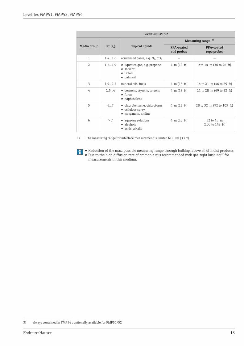
Measuring range The following table describes the media groups and the possible measuring range as a function ofthe media group.
Levelflex FMP51, FMP54
Media group DC (εr) Typical liquidsMeasuring range 1)
bare metallicrod probes
bare metallicrope probes
coax probes
1 1.4...1.6 condensed gases, e.g. N2, CO2 on request 6 m (20 ft)
2 1.6...1.9 • liquefied gas, e.g. propane• solvent• Freon• palm oil
• one-piece: 4 m (13 ft)• divisible: 10 m (33 ft)
15 to 22 m (49 to 72 ft) 6 m (20 ft)
3 1.9...2.5 mineral oils, fuels • one-piece: 4 m (13 ft)• divisible: 10 m (33 ft)
22 to 32 m (72 to 105 ft) 6 m (20 ft)
4 2.5...4 • benzene, styrene, toluene• furan• naphthalene
• one-piece: 4 m (13 ft)• divisible: 10 m (33 ft)
32 to 42 m(105 to 138 ft)
6 m (20 ft)
5 4...7 • chlorobenzene, chloroform• cellulose spray• isocyanate, aniline
• one-piece: 4 m (13 ft)• divisible: 10 m (33 ft)
42 to 45 m(138 to 148 ft)
6 m (20 ft)
6 > 7 • aqueous solutions• alcohols• ammonia
• one-piece: 4 m (13 ft)• divisible: 10 m (33 ft)
45 m (148 ft) 6 m (20 ft)
1) The measuring range for interface measurement is limited to 10 m (33 ft).
Levelflex FMP51, FMP52, FMP54
Endress+Hauser 13
Levelflex FMP52
Media group DC (εr) Typical liquidsMeasuring range 1)
PFA-coatedrod probes
PFA-coatedrope probes
1 1.4...1.6 condensed gases, e.g. N2, CO2 — —
2 1.6...1.9 • liquefied gas, e.g. propane• solvent• Freon• palm oil
4 m (13 ft) 9 to 14 m (30 to 46 ft)
3 1.9...2.5 mineral oils, fuels 4 m (13 ft) 14 to 21 m (46 to 69 ft)
4 2.5...4 • benzene, styrene, toluene• furan• naphthalene
4 m (13 ft) 21 to 28 m (69 to 92 ft)
5 4...7 • chlorobenzene, chloroform• cellulose spray• isocyanate, aniline
4 m (13 ft) 28 to 32 m (92 to 105 ft)
6 > 7 • aqueous solutions• alcohols• acids, alkalis
4 m (13 ft) 32 to 45 m(105 to 148 ft)
1) The measuring range for interface measurement is limited to 10 m (33 ft).
• Reduction of the max. possible measuring range through buildup, above all of moist products.• Due to the high diffusion rate of ammonia it is recommended with gas-tight bushing 3) for
measurements in this medium.
3) always contained in FMP54 ; optionally available for FMP51/52
Levelflex FMP51, FMP52, FMP54
14 Endress+Hauser
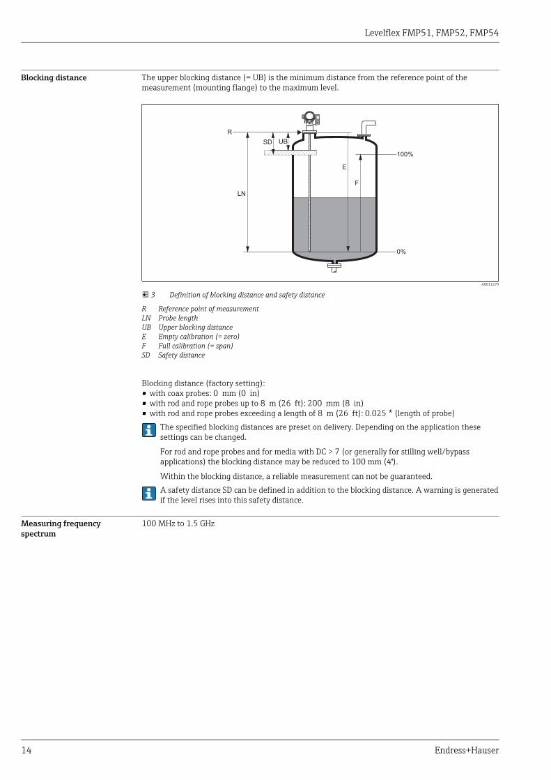
Blocking distance The upper blocking distance (= UB) is the minimum distance from the reference point of themeasurement (mounting flange) to the maximum level.
F
UB
E
100%
0%
LN
R
SD
A0011279
3 Definition of blocking distance and safety distance
R Reference point of measurementLN Probe lengthUB Upper blocking distanceE Empty calibration (= zero)F Full calibration (= span)SD Safety distance
Blocking distance (factory setting):• with coax probes: 0 mm (0 in)• with rod and rope probes up to 8 m (26 ft): 200 mm (8 in)• with rod and rope probes exceeding a length of 8 m (26 ft): 0.025 * (length of probe)
The specified blocking distances are preset on delivery. Depending on the application thesesettings can be changed.
For rod and rope probes and for media with DC > 7 (or generally for stilling well/bypassapplications) the blocking distance may be reduced to 100 mm (4").
Within the blocking distance, a reliable measurement can not be guaranteed.A safety distance SD can be defined in addition to the blocking distance. A warning is generatedif the level rises into this safety distance.
Measuring frequencyspectrum
100 MHz to 1.5 GHz

Levelflex FMP51, FMP52, FMP54
Endress+Hauser 15
Output
Output signal HART
Signal coding FSK ±0.5 mA over currency signal
Data transmission rate 1200 Baud
Galvanic isolation Yes
PROFIBUS PA
Signal coding Manchester Bus Powered (MBP)
Data transmission rate 31,25 KBit/s, voltage mode
Galvanic isolation Yes
FOUNDATION Fieldbus
Signal coding Manchester Bus Powered (MBP)
Data transmission rate 31,25 KBit/s, voltage mode
Galvanic isolation Yes
Switch output
For HART devices, the switch output is available as an option. See product structure, feature 20:"Power Supply, Output", option B: "2-wire; 4-20mA HART, switch output"
Devices with PROFIBUS PA and FOUNDATION Fieldbus always have a switch output.
Levelflex FMP51, FMP52, FMP54
16 Endress+Hauser
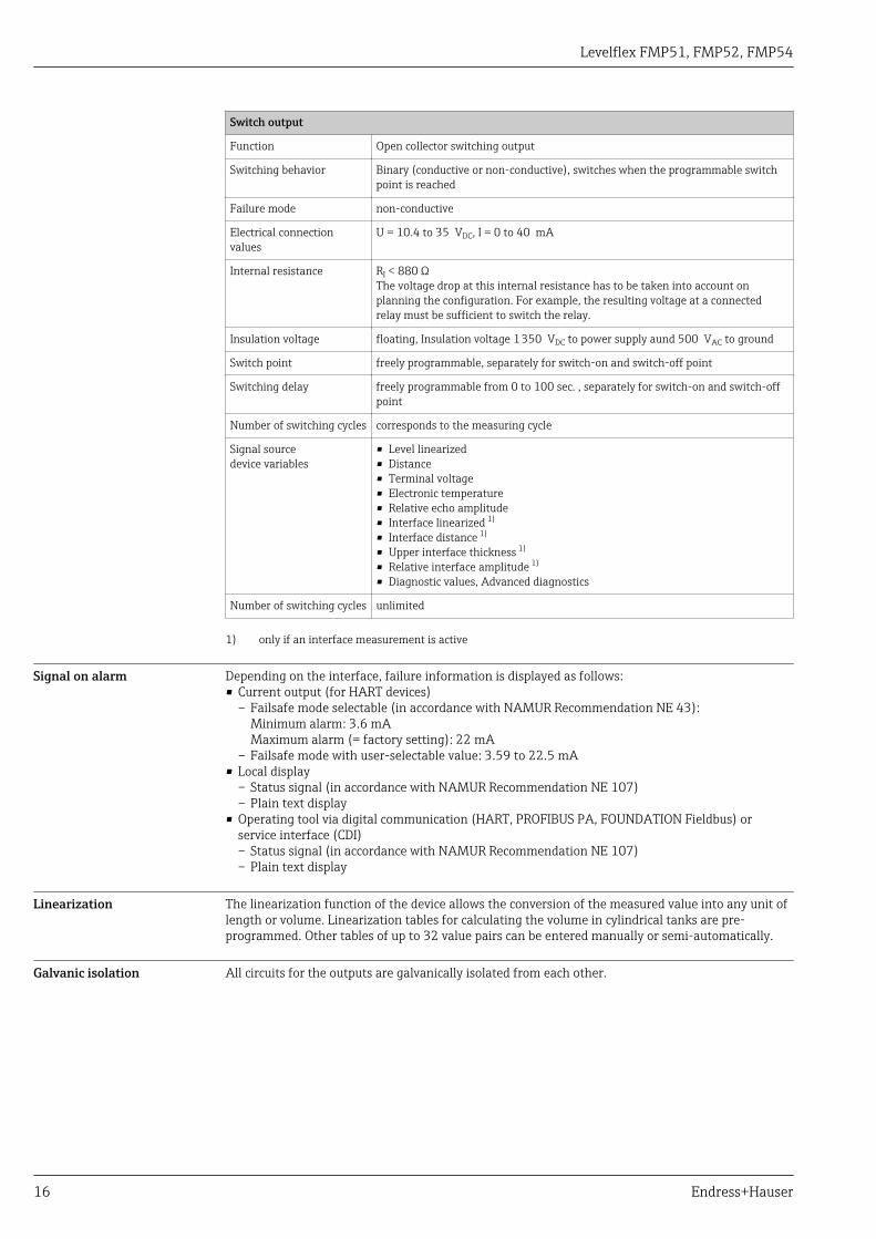
Switch output
Function Open collector switching output
Switching behavior Binary (conductive or non-conductive), switches when the programmable switchpoint is reached
Failure mode non-conductive
Electrical connectionvalues
U = 10.4 to 35 VDC, I = 0 to 40 mA
Internal resistance RI < 880 ΩThe voltage drop at this internal resistance has to be taken into account onplanning the configuration. For example, the resulting voltage at a connectedrelay must be sufficient to switch the relay.
Insulation voltage floating, Insulation voltage 1 350 VDC to power supply aund 500 VAC to ground
Switch point freely programmable, separately for switch-on and switch-off point
Switching delay freely programmable from 0 to 100 sec. , separately for switch-on and switch-offpoint
Number of switching cycles corresponds to the measuring cycle
Signal sourcedevice variables
• Level linearized• Distance• Terminal voltage• Electronic temperature• Relative echo amplitude• Interface linearized 1)
• Interface distance 1)
• Upper interface thickness 1)
• Relative interface amplitude 1)
• Diagnostic values, Advanced diagnostics
Number of switching cycles unlimited
1) only if an interface measurement is active
Signal on alarm Depending on the interface, failure information is displayed as follows:• Current output (for HART devices)
– Failsafe mode selectable (in accordance with NAMUR Recommendation NE 43):Minimum alarm: 3.6 mAMaximum alarm (= factory setting): 22 mA
– Failsafe mode with user-selectable value: 3.59 to 22.5 mA• Local display
– Status signal (in accordance with NAMUR Recommendation NE 107)– Plain text display
• Operating tool via digital communication (HART, PROFIBUS PA, FOUNDATION Fieldbus) orservice interface (CDI)– Status signal (in accordance with NAMUR Recommendation NE 107)– Plain text display
Linearization The linearization function of the device allows the conversion of the measured value into any unit oflength or volume. Linearization tables for calculating the volume in cylindrical tanks are pre-programmed. Other tables of up to 32 value pairs can be entered manually or semi-automatically.
Galvanic isolation All circuits for the outputs are galvanically isolated from each other.

Levelflex FMP51, FMP52, FMP54
Endress+Hauser 17
Protocol-specific data HART
Manufacturer ID 17 (0x11)
Device type ID 0x1122
HART specification 7.0
Device description files (DTM,DD)
Information and files at:• www.endress.com• www.hartcomm.org
HART load Min. 250 Ω
HART device variables The measured values can be freely assigned to the device variables.
Measured values for PV (primary variable)• Level linearized• Distance• Interface 1)
• Interface distance 1)
• Upper interface thickness 1)
• Electronic temperature• Relative echo amplitude• Relative interface amplitude 1)
Measured values for SV, TV, FV (second, third and fourth variable)• Level linearized• Distance• Interface linearized 1)
• Interface distance 1)
• Upper interface thickness 1)
• Terminal voltage• Electronic temperature• Absolute echo amplitude• Relative echo amplitude• Absolute interface amplitude 1)
• Relative interface amplitude 1)
• Calculated DC
Supported functions • Burst mode• Additional transmitter status
1) only if an interface measurement is active
Wireless HART data
Minimum start-up voltage for device version "2-wire; 4-20mA HART" 1): 17.5 V
Minimum start-up voltage for any other device version: 16.0 V
Start-up current 3.6 mA
Start-up time 45 s
Minimum operatingvoltage
11.4 V
Multidrop current 3.6 mA
Set-up time 1 s
1) Ordering feature 020: "Power supply; output", option A
Levelflex FMP51, FMP52, FMP54
18 Endress+Hauser
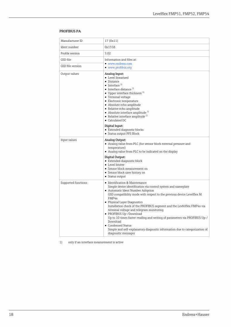
PROFIBUS PA
Manufacturer ID 17 (0x11)
Ident number 0x1558
Profile version 3.02
GSD file Information and files at:• www.endress.com• www.profibus.orgGSD file version
Output values Analog Input:• Level linearized• Distance• Interface 1)
• Interface distance 1)
• Upper interface thickness 1)
• Terminal voltage• Electronic temperature• Absolute echo amplitude• Relative echo amplitude• Absolute interface amplitude 1)
• Relative interface amplitude 1)
• Calculated DC
Digital Input:• Extended diagnostic blocks• Status output PFS Block
Input values Analog Output:• Analog value from PLC (for sensor block external pressure and
temperature)• Analog value from PLC to be indicated on the display
Digital Output:• Extended diagnostic block• Level limiter• Sensor block measurement on• Sensor block save history on• Status output
Supported functions • Identification & MaintenanceSimple device identification via control system and nameplate
• Automatic Ident Number AdoptionGSD compatibility mode with respect to the previous device Levelflex MFMP4x
• Physical Layer DiagnosticsInstallation check of the PROFIBUS segment and the Levfelflex FMP4x viaterminal voltage and telegram monitoring
• PROFIBUS Up-/DownloadUp to 10 times faster reading and writing of parameters via PROFIBUS Up-/Download
• Condensed StatusSimple and self-explanatory diagnostic information due to categorization ofdiagnostic messages
1) only if an interface measurement is active

Levelflex FMP51, FMP52, FMP54
Endress+Hauser 19
FOUNDATION Fieldbus
Manufacturer ID 0x452B48
Device type 0x1022
Device Revision 0x01
DD Revision Information and files at:• www.endress.com• www.fieldbus.orgCFF Revision
Device Tester Version (ITKVersion)
6.01
ITK Test Campaign Number IT080500
Link Master (LAS) capable yes
Link Master / Basic Deviceselectable
yes; default: Basic Device
Node address Default: 247 (0xF7)
Features supported Following methods are supported:• Restart• ENP Restart• Setup• Linearization• Self Check
Virtual Communication Relationships (VCRs)
Number of VCRs 44
Number of Link Objects in VFD 50
Permanent entries 1
Client VCRs 0
Server VCRs 10
Source VCRs 43
Sink VCRs 0
Subscriber VCRs 43
Publisher VCRs 43
Device Link Capabilities
Slot time 4
Min. inter PDU delay 8
Max. response delay 5

Levelflex FMP51, FMP52, FMP54
20 Endress+Hauser
Transducer Blocks
Block Content Output values
Setup Transducer Block Contains all parameters for a standard commissioningprocedure
• Level or volume 1)
(Channel 1)• Distance (Channel 2)
Advanced SetupTransducer Block
Contains all parameters for a more detailedconfiguration of the device
no output values
Display Transducer Block Contains all parameters for the configuration of thedisplay module
no output values
Diagnostic TransducerBlock
Contains diagnostic information no output values
Expert ConfigurationTransducer Block
Contains parameters which require detailedknowledge of the functionalities of the device
no output values
Expert InformationTransducer Block
Contains information about the state of the device no output values
Service Sensor TransducerBlock
Contains parameters which can only be operated byEndress+Hauser service personnel
no output values
Service InformationTransducer Block
Contains information on the state of device which isrelevant for service operations
no output values
Data Transfer TransducerBlock
Contains parameters which allow to backup the deviceconfiguration in the display module and to restore itinto the device.
no output values
1) depending on the configuration of the block
Levelflex FMP51, FMP52, FMP54
Endress+Hauser 21
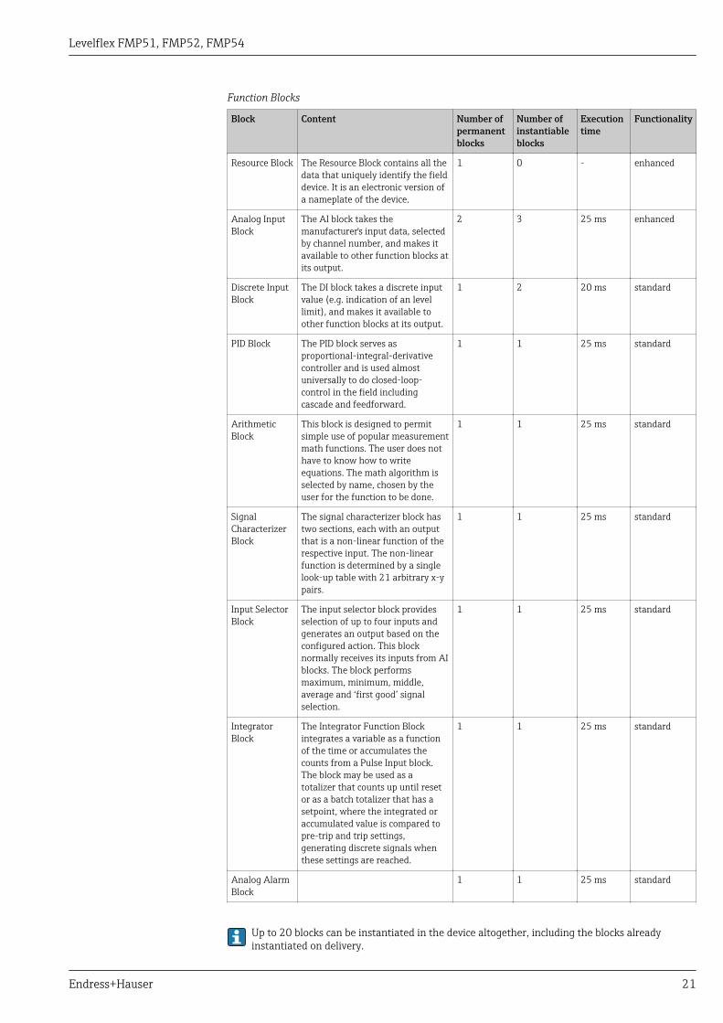
Function Blocks
Block Content Number ofpermanentblocks
Number ofinstantiableblocks
Executiontime
Functionality
Resource Block The Resource Block contains all thedata that uniquely identify the fielddevice. It is an electronic version ofa nameplate of the device.
1 0 - enhanced
Analog InputBlock
The AI block takes themanufacturer's input data, selectedby channel number, and makes itavailable to other function blocks atits output.
2 3 25 ms enhanced
Discrete InputBlock
The DI block takes a discrete inputvalue (e.g. indication of an levellimit), and makes it available toother function blocks at its output.
1 2 20 ms standard
PID Block The PID block serves asproportional-integral-derivativecontroller and is used almostuniversally to do closed-loop-control in the field includingcascade and feedforward.
1 1 25 ms standard
ArithmeticBlock
This block is designed to permitsimple use of popular measurementmath functions. The user does nothave to know how to writeequations. The math algorithm isselected by name, chosen by theuser for the function to be done.
1 1 25 ms standard
SignalCharacterizerBlock
The signal characterizer block hastwo sections, each with an outputthat is a non-linear function of therespective input. The non-linearfunction is determined by a singlelook-up table with 21 arbitrary x-ypairs.
1 1 25 ms standard
Input SelectorBlock
The input selector block providesselection of up to four inputs andgenerates an output based on theconfigured action. This blocknormally receives its inputs from AIblocks. The block performsmaximum, minimum, middle,average and ‘first good’ signalselection.
1 1 25 ms standard
IntegratorBlock
The Integrator Function Blockintegrates a variable as a functionof the time or accumulates thecounts from a Pulse Input block.The block may be used as atotalizer that counts up until resetor as a batch totalizer that has asetpoint, where the integrated oraccumulated value is compared topre-trip and trip settings,generating discrete signals whenthese settings are reached.
1 1 25 ms standard
Analog AlarmBlock
1 1 25 ms standard
Up to 20 blocks can be instantiated in the device altogether, including the blocks alreadyinstantiated on delivery.

Levelflex FMP51, FMP52, FMP54
22 Endress+Hauser
Power supply
Terminal assignment 2-wire: 4-20mA HART
+
–
4...20 mA
4...20 mA
5
5
4
4
1
1
2
2
8
9
3
3
+
+
–
–
1+
2
4...2
0m
AH
AR
T
10
mm
Spare part71108xxx
2- wire level4-20 mA
4-20 mA
HART[21]open
-
1+
24-20mA
1-channel overvoltage protection
-
71128617
[16]
A
+
–
7
B
6
!
!
A0011294
4 Terminal assignment 2-wire; 4-20mA HART
A Without integrated overvoltage protectionB With integrated overvoltage protection1 Active barrier with power supply (e.g. RN221N): Observe terminal voltage2 HART communication resistor (≥250 Ω): Observe maximum load3 Connection for Commubox FXA195 or FieldXpert SFX350/SFX370 (via VIATOR Bluetooth modem)4 Analog display device: Observe maximum load5 Cable screen; observe cable specification6 4-20mA HART (passive): Terminals 1 and 27 Overvoltage protection module8 Terminal for potential equalization line9 Cable entry

Levelflex FMP51, FMP52, FMP54
Endress+Hauser 23
2-wire: 4-20mA HART, switch output
1
3+
+
2
4
4-20mA/FIELDBUS
4-20mA/2-channel overvoltage protection
-
-
71128619
[17]
B
1+
2
4...2
0m
AH
AR
T
10
mm
Spare part71108xxx
2- wire4-20 mAPFS
HART[02/03] open
-
A
1+
2-3
+
4-
10
9
8
7
11
+
+
-
-
2
2
3
3
4
4
6
5
5
1
1
4...20 mA
4...20 mA
³ W250
³ W250
3+
3+
4-
4-
+
+
–
–
A0013759
5 Terminal assignment 2-wire; 4-20mA HART, switch output
A Without integrated overvoltage protectionB With integrated overvoltage protection1 Active barrier with power supply (e.g. RN221N): Observe terminal voltage2 HART communication resistor (≥250 Ω): Observe maximum load3 Connection for Commubox FXA195 or FieldXpert SFX350/SFX370 (via VIATOR Bluetooth modem)4 Analog display device: Observe maximum load5 Cable screen; observe cable specification6 4-20mA HART (passive): Terminals 1 and 27 Switch output (open collector): Terminals 3 and 48 Terminal for potential equalization line9 Cable entry for 4-20mA HART line10 Cable entry for switch output line11 Overvoltage protection module

Levelflex FMP51, FMP52, FMP54
24 Endress+Hauser
2-wire: 4-20mA HART, 4-20mA
1
3+
+
2
4 4...2
0m
AH
AR
T4...2
0m
A
10
mm
Spare part71108xxx
2- wire level4-20 mA
4-20 mA
HART[04/05] open
-
-11
A
1
3+
+
2
4
4-20mA/FIELDBUS
4-20mA/2-channel overvoltage protection
-
-
71128619
[17]
14
13
12
+
+
+
++
-
-
-
-
1
1
2
2
3
3
9
9
5
5
8
8
6
6
7
7
4
4
4
4
+
+
–
–
+
+
–
–
4...20 mA
4...20 mA
10
B
4...20 mA
4...20 mA
A0013923
6 Terminal assignment 2-wire, 4-20 mA HART, 4...20mA
A Without integrated overvoltage protectionB With integrated overvoltage protection1 Connection current output 22 Connection current output 13 Supply voltage for current output 1 (e.g. RN221N); Observe terminal voltage4 Cable screen; observe cable specification5 HART communication resistor (≥250 Ω): Observe maximum load6 Connection for Commubox FXA195 or FieldXpert SFX350/SFX370 (via VIATOR Bluetooth modem)7 Analog display device ; observe maximum load8 Analog display device ; observe maximum load9 Supply voltage for current output 2 (e.g. RN221N); Obeserve terminal voltage10 Overvoltage protection module11 Current output 2: Terminals 3 and 412 Terminal for the potential equalization line13 Cable entry for current output 114 Cable entry for current output 2
This version is also suited for single-channel operation. In this case, current output 1 (terminals1 and 2) must be used.

Levelflex FMP51, FMP52, FMP54
Endress+Hauser 25
4-wire: 4-20mA HART (10.4 to 48 VDC)
3
1+
L+
4
2 4...2
0m
AH
AR
T
10.4
...4
8V
=
10
mm
Spare part71108xxx
2- wire4-20 mAHART[08]open
-
L-
A
13
12
11
910
+
-
2 3 4
6
7
8
51
4...20 mA³ W250
A0011340
7 Terminal assignment 4-wire; 4-20mA HART (10.4 to 48 VDC)
1 Evaluation unit, e.g. PLC2 HART communication resistor (≥250 Ω): Observe maximum load3 Connection for Commubox FXA195 or FieldXpert SFX350/SFX370 (via VIATOR Bluetooth modem)4 Analog display device: Observe maximum load5 Signal cable including screening (if required), observe cable specification6 Protective connection; do not disconnect!7 Protective earth, observe cable specification8 4...20mA HART (active): Terminals 3 and 49 Supply voltage: Terminals 1 and 210 Supply voltage: Observe terminal voltage, observe cable specification11 Terminal for potential equalization12 Cable entry for signal line13 Cable entry for power supply
Levelflex FMP51, FMP52, FMP54
26 Endress+Hauser
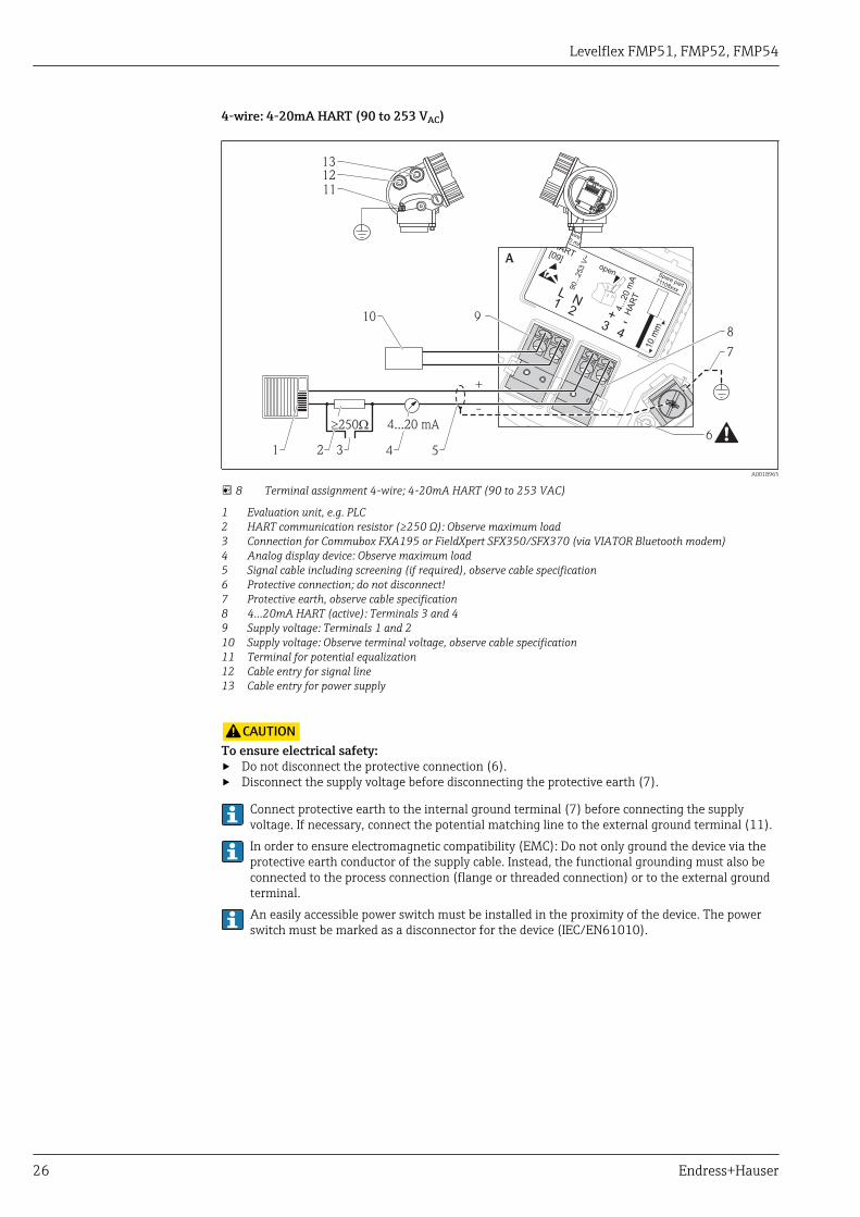
4-wire: 4-20mA HART (90 to 253 VAC)
3
1+
L
4
2 4...2
0m
AH
AR
T
90...2
53
V~
10
mm
Spare part71108xxx
2- wire4-20 mAHART[09]open
-
N
A
13
12
11
910
+
-
2 3 4
6
7
8
51
4...20 mA³ W250
A0018965
8 Terminal assignment 4-wire; 4-20mA HART (90 to 253 VAC)
1 Evaluation unit, e.g. PLC2 HART communication resistor (≥250 Ω): Observe maximum load3 Connection for Commubox FXA195 or FieldXpert SFX350/SFX370 (via VIATOR Bluetooth modem)4 Analog display device: Observe maximum load5 Signal cable including screening (if required), observe cable specification6 Protective connection; do not disconnect!7 Protective earth, observe cable specification8 4...20mA HART (active): Terminals 3 and 49 Supply voltage: Terminals 1 and 210 Supply voltage: Observe terminal voltage, observe cable specification11 Terminal for potential equalization12 Cable entry for signal line13 Cable entry for power supply
LCAUTIONTo ensure electrical safety:‣ Do not disconnect the protective connection (6).‣ Disconnect the supply voltage before disconnecting the protective earth (7).
Connect protective earth to the internal ground terminal (7) before connecting the supplyvoltage. If necessary, connect the potential matching line to the external ground terminal (11).In order to ensure electromagnetic compatibility (EMC): Do not only ground the device via theprotective earth conductor of the supply cable. Instead, the functional grounding must also beconnected to the process connection (flange or threaded connection) or to the external groundterminal.An easily accessible power switch must be installed in the proximity of the device. The powerswitch must be marked as a disconnector for the device (IEC/EN61010).

Levelflex FMP51, FMP52, FMP54
Endress+Hauser 27
PROFIBUS PA / FOUNDATION Fieldbus
1
3+
+
2
4
FIELDBUS
2-channel overvoltage protection
-
-
71128619
[17]
4-20mA/
4-20mA/
B
1
1+
+
2
2 FIE
LD
BU
S
Spare part71023457
PA/FF[06/07]
FIELDBUS
-
-
1
3+
+
2
4 PA
/FF
10
mm
Spare part71108xxx
2- wire level4-20 mA
PFS
FIELDBUS[26/27] open
-
-
A
4
1
1
2
3
6
5
3+
3+
4-
4-
A0011341
9 Terminal assignment PROFIBUS PA / FOUNDATION Fieldbus
A Without integrated overvoltage protectionB With integrated overvoltage protection1 Cable screen: Observe cable specifications2 Switch output (open collector): Terminals 3 and 43 PROFIBUS PA / FOUNDATION Fieldbus: Terminals 1 and 24 Terminal for potential equalization line5 Cable entries6 Overvoltage protection module

Levelflex FMP51, FMP52, FMP54
28 Endress+Hauser
Connection examples for the switch output
For HART devices, the switch output is available as an option. See product structure, feature 20:"Power Supply, Output", option B: "2-wire; 4-20mA HART, switch output"
Devices with PROFIBUS PA and FOUNDATION Fieldbus always have a switch output.
3+
+-
4-
A0015909
10 Connection of a relay
Suitable relays (examples):• Solid-state relay: Phoenix Contact OV-24DC/480AC/5 with
mounting rail connector UMK-1 OM-R/AMS• Electromechanical relay: Phoenix Contact PLC-RSC-12DC/21
3+2
1
+
4-
A0015910
11 Connection of a digital input
1 Pull-up resistor2 Digital input
For optimum interference immunity we recommend to connect an external resistor (internalresistance of the relay or Pull-up resistor) of < 1 000 Ω.

Levelflex FMP51, FMP52, FMP54
Endress+Hauser 29
HART loop converter HMX50
The dynamic variables of the HART protocol can be converted into individual 4 to 20 mA sectionsusing the HART loop converter HMX50. The variables are assigned to the current output and themeasuring ranges of the individual parameters are defined in the HMX50.
Stromausgang 1
Relais 1
Stromausgang 2
Stromausgang 3
Relais 2
versorgung
Eingang1
2
3
4
5
6
7
8
9
1112
13
14
15
19
20
21
16
17
18
22 23 24
24V DC
10
HMX50
HART
FXA195
+
-
+
HART
A0023287
12 Connection diagram for HART loop converter HMX50 (example: passive 2-wire device and current outputsconnected as power source)
The HART loop converter HMX50 can be acquired using the order number 71063562.
Additional documentation: TI00429F and BA00371F.
Levelflex FMP51, FMP52, FMP54
30 Endress+Hauser
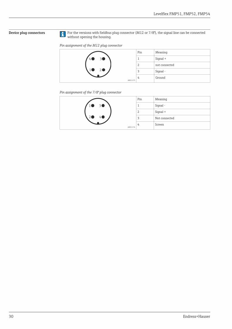
Device plug connectors For the versions with fieldbus plug connector (M12 or 7/8"), the signal line can be connectedwithout opening the housing.
Pin assignment of the M12 plug connector
21
34
A0011175
Pin Meaning
1 Signal +
2 not connected
3 Signal -
4 Ground
Pin assignment of the 7/8" plug connector
2
1
4
3
A0011176
Pin Meaning
1 Signal -
2 Signal +
3 Not connected
4 Screen

Levelflex FMP51, FMP52, FMP54
Endress+Hauser 31
Power supply An external power supply is required.
Various supply units can be ordered from Endress+Hauser: see "Accessories" section → 124
2-wire, 4-20mA HART, passive
2-wire; 4-20mA HART 1)
"Approval" 2) Terminal voltage U at the device Maximum load R, depending on the supply voltage U0 at thesupply unit
• Non-Ex• Ex nA• CSA GP
11.5 to 35 V 3)R [ ]W
[V]U010
11.5 22.5
20 30 35
0
500
A0014076
Ex ic 11.5 to 32 V
Ex ia / IS 11.5 to 30 V
• Ex d / XP• Ex ic[ia]• Ex tD / DIP
13.5 to 30 V 4)R [ ]W
[V]U010
13.5 24.5
20 30
0
500
A0014077
1) Feature 020 of the product structure: option A2) Feature 010 of the product structure3) For ambient temperatures Ta≤ -30 °C (-22 °F) a minimum voltage of 14 V is required for the sartup of the device at the MIN error current (3,6
mA). The startup current can be parametrized. If the device is operated with a fixed current I ≥ 4,5 mA (HART multidrop mode), a voltage of U ≥11,5 V is sufficient throughout the entire range of ambient temperatures.
4) For ambient temperatures Ta≤ -20 °C (-4 °F) a minimum voltage of 16 V is required for the startup of the device at the MIN error current (3.6mA).
2-wire; 4-20 mA HART, switch output 1)
"Approval" 2) Terminal voltage U at the device Maximum load R, depending on the supply voltage U0 at thesupply unit
• Non-Ex• Ex nA• Ex nA[ia]• Ex ic• Ex ic[ia]• Ex d[ia] / XP• Ex ta / DIP• CSA GP
12 to 35 V 3)R [ ]W
U0 [V]1012 23
20 30 35
0
500
A0019136
• Ex ia / IS• Ex ia + Ex d[ia] / IS + XP
12 to 30 V 3)
1) Feature 020 of the product structure: option B2) Feature 010 of the product structure3) For ambient temperatures Ta≤ -30 °C (-22 °F) a minimum voltage of 14 V is required for the startup of the device at the MIN error current (3.6
mA).

Levelflex FMP51, FMP52, FMP54
32 Endress+Hauser
2-wire; 4-20mA HART, 4-20mA 1)
"Approval" 2) Terminal voltage U at the device Maximum load R, depending on the supply voltage U0 at thesupply unit
alle Channel 1:
13.5 to 30 V 3)R [ ]W
[V]U010
13.5 24.5
20 30
0
500
A0014077
Channel 2:
12 to 30 V R [ ]W
VU0 [ ]1012 23
20 30
0
500
A0022583
1) Feature 020 of the product structure: option C2) Feature 010 of the product structure3) For ambient temperatures Ta≤ -30 °C (-22 °F) a minimum voltage of 16 V is required for the startup of the device at the MIN error current (3.6
mA).
Polarity reversalprotection
Yes
Admissible residual rippleat f = 0 to 100 Hz
USS < 1 V
Admissible residual rippleat f = 100 to 10000 Hz
USS < 10 mV

Levelflex FMP51, FMP52, FMP54
Endress+Hauser 33
4-wire, 4-20mA HART, active
"Power supply; Output" 1) Terminal voltage Maximum load Rmax
K: 4-wire 90-253VAC; 4-20mA HART 90 to 253 VAC (50 to 60 Hz), overvoltagecategory II
500 Ω
L: 4-wire 10,4-48VDC; 4-20mA HART 10.4 to 48 VDC
1) Feature 020 of the product structure
PROFIBUS PA, FOUNDATION Fieldbus
"Power supply; Output" 1) "Approval" 2) Terminal voltage
E: 2-wire; FOUNDATION Fieldbus, switch outputG: 2-wire; PROFIBUS PA, switch output
• Non-Ex• Ex nA• Ex nA[ia]• Ex ic• Ex ic[ia]• Ex d[ia] / XP• Ex ta / DIP• CSA GP
9 to 32 V 3)
• Ex ia / IS• Ex ia + Ex d[ia] / IS + XP
9 to 30 V
1) Feature 020 of the product structure2) Feature 010 of the product structure3) Input voltages up to 35 V will not spoil the device.
Polarity sensitive No
FISCO/FNICO compliantaccording to IEC 60079-27
Yes
Power consumption "Power supply; Output" 1) Power consumption
A: 2-wire; 4-20mA HART < 0.9 W
B: 2-wire; 4-20mA HART, switch output < 0.9 W
C: 2-wire; 4-20mA HART, 4-20mA < 2 x 0.7 W
K: 4-wire 90-253VAC; 4-20mA HART 6 VA
L: 4-wire 10,4-48VDC; 4-20mA HART 1.3 W
1) Feature 020 of the product structure
Current consumption HART
Nominal current 3.6 to 22 mA, the start-up current for multidrop mode can be parametrized (isset to 3.6 mA on delivery)
Breakdown signal(NAMUR NE43)
adjustable: 3.59 to 22.5 mA
PROFIBUS PA
Nominal current 14 mA
Error current FDE (FaultDisconnection Electronic)
0 mA

Levelflex FMP51, FMP52, FMP54
34 Endress+Hauser
FOUNDATION Fieldbus
Device basic current 15 mA
Error current FDE (FaultDisconnection Electronic)
0 mA
FISCO
Ui 17.5 V
Ii 550 mA
Pi 5.5 W
Ci 5 nF
Li 10 μH
Power supply failure • Configuration is retained in the HistoROM (EEPROM).• Error messages (incl. value of operated hours counter) are stored.
Potential equalization No special measures for potential equalization are required.
If the device is designed for hazardous areas, observe the information in the documentation"Safety Instructions" (XA, ZD).
Terminals • Without integrated overvoltage protectionPlug-in spring terminals for wire cross-sections 0.5 to 2.5 mm2 (20 to 14 AWG)
• With integrated overvoltage protectionScrew terminals for wire cross-sections 0.2 to 2.5 mm2 (24 to 14 AWG)
Cable entries Connection of power supply and signal line
To be selected in feature 050 "Electrical connection"• Gland M20; Material dependent on the approval:
– For Non-Ex, ATEX, IECEx, NEPSI Ex ia/ic:Plastics M20x1.5 for cable 5 to 10 mm (0.2 to 0.39 in)
– For Dust-Ex, FM IS, CSA IS, CSA GP, Ex nA:Metal M20x1.5 for cable 7 to 10 mm (0.28 to 0.39 in) 4)
– For Ex d:No gland available
• Thread– ½" NPT– G ½"– M20 × 1.5
• Plug M12 / Plug 7/8"Only available for Non-Ex, Ex ic, Ex ia
Connection of remote display FHX50
Dependent on feature 030: "Display, Operation":• "Prepared for display FHX50 + M12 connection":
M12 socket• "Prepared for display FHX50 + custom connection":
M16 cable gland
Cable specification • Minimum cross-section: dependent on terminals → 34• For ambient temperature TU≥60 °C (140 °F): use cable for temperature TU +20 K.
4) The material of the gland is dependent on the housing type; GT18 (stainless steel housing): 316L (1.4404); GT19 (plastic housing) and GT20(aluminum housing): nickel-coated brass (CuZn).

Levelflex FMP51, FMP52, FMP54
Endress+Hauser 35
HART
• A normal device cable suffices if only the analog signal is used.• A shielded cable is recommended if using the HART protocol. Observe grounding concept of the
plant.• For 4-wire devices: Standard device cable is sufficient for the power line.
PROFIBUS
Use a twisted, screened two-wire cable, preferably cable type A.For further information on the cable specifications, see Operating Instructions BA00034S"Guidelines for planning and commissioning PROFIBUS DP/PA", PNO Guideline 2.092"PROFIBUS PA User and Installation Guideline" and IEC61158-2 (MBP).
FOUNDATION Fieldbus
Endress+Hauser recommends using twisted, shielded two-wire cables.For further information on the cable specifications, see Operating Instructions BA00013S"FOUNDATION Fieldbus Overview", FOUNDATION Fieldbus Guideline and IEC 61158-2 (MBP).
Overvoltage protection If the measuring device is used for level measurement in flammable liquids which requires the use ofovervoltage protection according to DIN EN 60079-14, standard for test procedures 60060-1 (10kA, pulse 8/20 μs), overvoltage protection has to be ensured by an integrated or externalovervoltage protection module.
Integrated overvoltage protection
An integrated overvoltage protection module is available for 2-wire HART as well as PROFIBUS PAand FOUNDATION Fieldbus devices.
Product structure: Feature 610 "Accessory mounted", option NA "Overvoltage protection".
Technical data
Resistance per channel 2 * 0.5 Ω max
Threshold DC voltage 400 to 700 V
Threshold impulse voltage < 800 V
Capacitance at 1 MHz < 1.5 pF
Nominal arrest impulse voltage (8/20 μs) 10 kA
External overvoltage protection
HAW562 or HAW569 from Endress+Hauser are suited as external overvoltage protection.
For detailed information please refer to the following documents:• HAW562: TI01012K• HAW569: TI01013K
Levelflex FMP51, FMP52, FMP54
36 Endress+Hauser
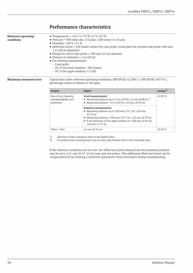
Performance characteristics
Reference operatingconditions
• Temperature = +24 °C (+75 °F) ±5 °C (±9 °F)• Pressure = 960 mbar abs. (14 psia) ±100 mbar (±1.45 psi)• Humidity = 60 % ±15 %• Reflection factor ≥ 0,8 (water surface for coax probe, metal plate for rod and rope probe with min.
1 m (40 in) diameter)• Flange for rod or rope probe ≥ 300 mm (12 in) diameter• Distance to obstacles ≥ 1 m (40 in)• For interface measurement:
– Coax probe– DC of the lower medium = 80 (water)– DC of the upper medium = 2 (oil)
Maximum measured error Typical data under reference operating conditions: DIN EN IEC 61298-2 / DIN EN IEC 60770-1,percentage values in relation to the span.
Output: digital analog 1)
Sum of non-linearity,nonrepeatability andhysteresis
Level measurement:• Measuring distance up to 15 m (49 ft): ±2 mm (0.08 in) 2)
• Measuring distance >15 m (49 ft): ±10 mm (0.39 in)
±0.02 %
Interface measurement:• Measuring distance up to 500 mm (19.7 in): ±20 mm
(0.79 in)• Measuring distance >500 mm (19.7 in): ±10 mm (0.39 in)• If the thickness of the upper medium is <100 mm (3.94 in):
±40 mm (1.57 in)
Offset / Zero ±4 mm (0.16 in) ±0.03 %
1) Add error of the analogous value to the digital value.2) For probes with centering stars, the accuracy may deviate close to the centering stars.
If the reference conditions are not met, the offset/zero point arising from the mounting situationmay be up to ±12 mm (0.47 in) for rope and rod probes. This additional offset/zero point can becompensated for by entering a correction (parameter "level correction") during commissioning.
Levelflex FMP51, FMP52, FMP54
Endress+Hauser 37
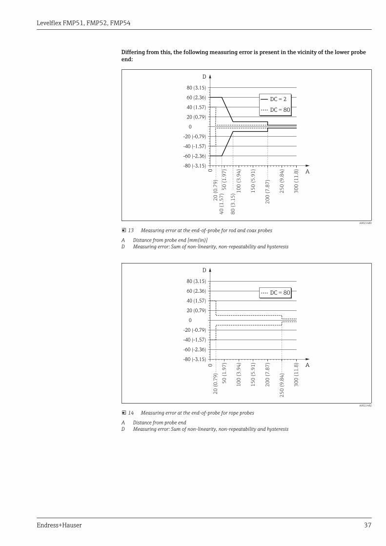
Differing from this, the following measuring error is present in the vicinity of the lower probeend:
-80 (-3.15)
-60 (-2.36)
-40 (-1.57)
-20 (-0.79)
0
20 (0.79)
40 (1.57)
60 (2.36)
80 (3.15)
0 A
D
DC = 2
DC = 80
50
(1
.97
)
10
0 (
3.9
4)
15
0 (
5.9
1)
20
0 (
7.8
7)
40
(1
.57
)
80
(3
.15
)
20
(0
.79
)
25
0 (
9.8
4)
30
0 (
11
.8)
A0021480
13 Measuring error at the end-of-probe for rod and coax probes
A Distance from probe end [mm(in)]D Measuring error: Sum of non-linearity, non-repeatability and hysteresis
-80 (-3.15)
-60 (-2.36)
-40 (-1.57)
-20 (-0.79)
0
20 (0.79)
40 (1.57)
60 (2.36)
80 (3.15)
0
DC = 80
A
D
50
(1
.97
)
10
0 (
3.9
4)
15
0 (
5.9
1)
20
0 (
7.8
7)
20
(0
.79
)
25
0 (
9.8
4)
30
0 (
11
.8)
A0021482
14 Measuring error at the end-of-probe for rope probes
A Distance from probe endD Measuring error: Sum of non-linearity, non-repeatability and hysteresis

Levelflex FMP51, FMP52, FMP54
38 Endress+Hauser
-80 (-3.15)
-100 (-3.94)
-120 (-4.72)
-60 (-2.36)
-40 (-1.57)
-20 (-0.79)
0
20 (0.79)
40 (1.57)
60 (2.36)
80 (3.15)
100 (3.94)
120 (4.72)
DC = 2
DC = 80
30
(0
.79
)
A
D
0
50
(1
.97
)
10
0 (
3.9
4)
15
0 (
5.9
1)
20
0 (
7.8
7)
25
0 (
9.8
4)
30
0 (
11
.8)
A0021483
15 Measuring error at the end-of-probe for probes with metallic centering disk (product structure: feature610 "Accessory mounted", option OA, OB or OC)
A Distance from probe end [mm(in)]D Measuring error: Sum of non-linearity, non-repeatability and hysteresis
If for rope probes the DC value is less than 7, then measurement is not possible in the area ofthe straining weight (0 to 250 mm from end of probe; lower blocking distance).
Levelflex FMP51, FMP52, FMP54
Endress+Hauser 39
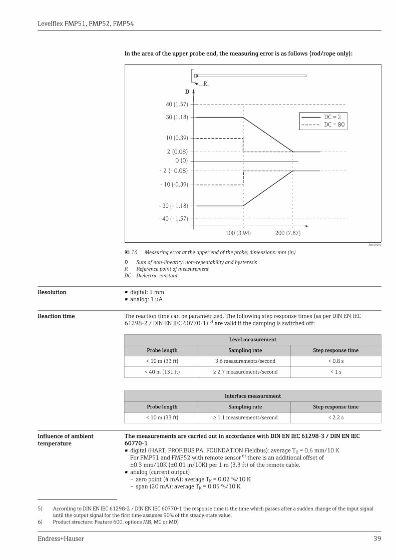
In the area of the upper probe end, the measuring error is as follows (rod/rope only):
2 (0.08)
0 (0)
- 2 (- 0.08)
100 (3.94) 200 (7.87)
10 (0.39)
- 10 (-0.39)
30 (1.18)
- 30 (- 1.18)
40 (1.57)
- 40 (- 1.57)
R
D
DC = 2
DC = 80
A0015091
16 Measuring error at the upper end of the probe; dimensions: mm (in)
D Sum of non-linearity, non-repeatability and hysteresisR Reference point of measurementDC Dielectric constant
Resolution • digital: 1 mm• analog: 1 μA
Reaction time The reaction time can be parametrized. The following step response times (as per DIN EN IEC61298-2 / DIN EN IEC 60770-1) 5) are valid if the damping is switched off:
Level measurement
Probe length Sampling rate Step response time
< 10 m (33 ft) 3.6 measurements/second < 0.8 s
< 40 m (131 ft) ≥ 2.7 measurements/second < 1 s
Interface measurement
Probe length Sampling rate Step response time
< 10 m (33 ft) ≥ 1.1 measurements/second < 2.2 s
Influence of ambienttemperature
The measurements are carried out in accordance with DIN EN IEC 61298-3 / DIN EN IEC60770-1• digital (HART, PROFIBUS PA, FOUNDATION Fieldbus): average TK = 0.6 mm/10 K
For FMP51 and FMP52 with remote sensor 6) there is an additional offset of±0.3 mm/10K (±0.01 in/10K) per 1 m (3.3 ft) of the remote cable.
• analog (current output):– zero point (4 mA): average TK = 0.02 %/10 K– span (20 mA): average TK = 0.05 %/10 K
5) According to DIN EN IEC 61298-2 / DIN EN IEC 60770-1 the response time is the time which passes after a sudden change of the input signaluntil the output signal for the first time assumes 90% of the steady-state value.
6) Product structure: Feature 600, options MB, MC or MD)

Levelflex FMP51, FMP52, FMP54
40 Endress+Hauser
Influence of gas layer High pressures reduce the propagation velocity of the measuring signals in the gas/vapor above thefluid. This effect depends on the kind of gas/vapor and of its temperature. This results in asystematic measuring error that gets bigger as the distance increases between the reference point ofthe measurement (flange) and the product surface. The following table illustrates this measurederror for a few typical gases/vapors (with regard to distance; a positive value means that too large adistance is being measured):
Gas layer Temperature Pressure
°C °F 1 bar (14.5 psi) 10 bar (145 psi) 50 bar (725 psi) 100 bar (1450 psi) 200 bar (2900 psi) 400 bar (5800 psi)
Air 20 68 0.00 % 0.22 % 1.2 % 2.4 % 4.9 % 9.5 %
200 392 -0.01 % 0.13 % 0.74 % 1.5 % 3.0 % 6.0 %
400 752 -0.02 % 0.08 % 0.52 % 1.1 % 2.1 % 4.2 %
Hydrogen 20 68 -0.01 % 0.10 % 0.61 % 1.2 % 2.5 % 4.9 %
200 392 -0.02 % 0.05 % 0.37 % 0.76 % 1.6 % 3.1 %
400 752 -0.02 % 0.03 % 0.25 % 0.53 % 1.1 % 2.2 %
Gas layer Temperature Pressure
°C °F 1 bar(14.5 psi)
2 bar(29 psi)
5 bar(72.5 psi)
10 bar(145 psi)
20 bar(290 psi)
50 bar(725 psi)
100 bar(1450 psi)
200 bar(2900 psi)
Water(saturated
steam)
100 212 0.26 % - - - - - - -
120 248 0.23 % 0.50 % - - - - - -
152 306 0.20 % 0.42 % 1.14 % - - - - -
180 356 0.17 % 0.37 % 0.99 % 2.10 % - - - -
212 414 0.15 % 0.32 % 0.86 % 1.79 % 3.9 % - - -
264 507 0.12 % 0.26 % 0.69 % 1.44 % 3.0 % 9.2 % - -
311 592 0.09 % 0.22 % 0.58 % 1.21 % 2.5 % 7.1 % 19.3 % -
366 691 0.07 % 0.18 % 0.49 % 1.01 % 2.1 % 5.7 % 13.2 % 76 %
Gas phase compensationwith external pressuresensor (PROFIBUS PA /FOUNDATION Fieldbus)
PROFIBUS and FOUNDATION Fieldbus devices can receive the signal of an external pressure sensorthrough the bus and use it to perform a pressure dependent time-of-flight correction. In the case ofsaturated steam in the temperature range from 100 to 350 °C (212 to 662 °f), for example, themeasuring error of the distance measurement can be reduced by this method from up to 29 %(without compensation) to less than 3 % (with compensation).

Levelflex FMP51, FMP52, FMP54
Endress+Hauser 41
Gas phase compensationwith reference signal (optionfor FMP54)
Under high pressure the propagation speed of microwave signals is reduced in the steam (polarmedia) above the liquid to be measured. As a result, the Levelflex indicates the level too low→ 40.
As an option Levelflex is available in a version with automatic gas phase correction, which correctsthis error (feature 540 "Application Package", option EF: "Gas Phase Compensation Lref= 300 mm" orEG: "Gas Phase Compensation Lref= 550 mm"). This version of the Levelflex generates a referencereflection in the distance Lref from the flange by a diameter step of the probe rod. The referencereflection must be at least 150 mm (6") above the highest level. By means of the shift of thereference reflection the actual propagation speed is measured and the level value will beautomatically corrected.
A0014534
17 FMP54 with reference signal for gas phase compensation; dimensions: mm (in)
Coax probes with reference reflection can be installed in any tank (free in the tank or into abypass). Coax probes are completely mounted and adjusted ex works. After mounting they areready for use, additional settings are not necessary.Rod probes are only recommended if the installation of a coax probe is not possible (e.g. if thebypass diameter is too small).
Rod probes with reference reflection are only suited for mounting in stilling wells and sidegauges (bypasses). The diameter Dref of the probe rod in the range of the reference distance Lrefmust be chosen depending on the pipe inner diameter iD, see table below. In the range of thereference distance Lref the pipe has to be cylindrical; changes of the cross section, for example atflanged connections, are only allowed up to 5% of the inside diamter iD.
Additionally, the settings must be checked by an expert person after mounting and corrected ifnecessary.
Inner diameter iD of the stilling well/bypass Diameter Dref of the rod probe within the reference distanceLref
40 mm (1.57") ≤ iD < 45 mm (1.77") 22 mm (0.87")
45 mm (1.77") ≤ iD < 70 mm (2.76") 25 mm (0.98")
70 mm (2.76") ≤ iD < 100 mm (3.94") 30 mm (1.18")
Levelflex FMP51, FMP52, FMP54
42 Endress+Hauser
Limitations for coax/rod probes
Maximum probe length LN • For rod probes:LN ≤ 4 000 mm (157 in)
• For coax probes:LN ≤ 6 000 mm (236 in)
Minimum probe length LN LN > Lref + 200 mm (Lref + 7.7")
Reference distance Lref 300 mm (11.8") or 550 mm (21.7"), see feature 540 of the productstructure
Maximum level relative to sealingsurface of flange
Lref + 150 mm (Lref + 6")
Minimum dielectric constant of themedium
DC > 7
Area of application
Level measurements with high pressure for measuring ranges up to a few meters in polar media witha dielectric constant DC > 7 (e.g. water or ammonia), which would cause a high measuring errorwithout the compensation.
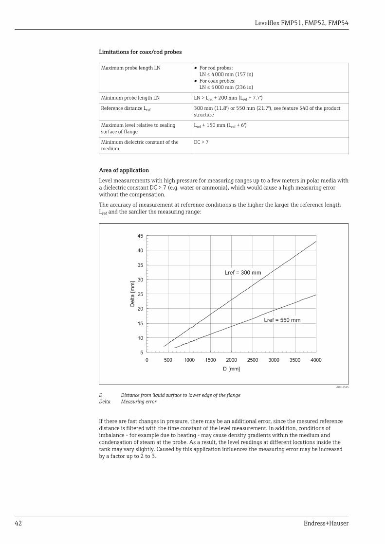
The accuracy of measurement at reference conditions is the higher the larger the reference lengthLref and the samller the measuring range:
5
10
15
20
25
30
35
40
45
0 500 1000 1500 2000 2500 3000 3500 4000
D [mm]
Delta
[mm
]
Lref = 550 mm
Lref = 300 mm
A0014535
D Distance from liquid surface to lower edge of the flangeDelta Measuring error
If there are fast changes in pressure, there may be an additional error, since the mesured referencedistance is filtered with the time constant of the level measurement. In addition, conditions ofimbalance - for example due to heating - may cause density gradients within the medium andcondensation of steam at the probe. As a result, the level readings at different locations inside thetank may vary slightly. Caused by this application influences the measuring error may be increasedby a factor up to 2 to 3.
Levelflex FMP51, FMP52, FMP54
Endress+Hauser 43
Mounting
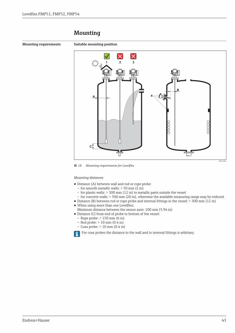
Mounting requirements Suitable mounting position
A
C
1 2 3
4
B
A0012606
18 Mounting requirements for Levelflex
Mounting distances
• Distance (A) between wall and rod or rope probe:– for smooth metallic walls: > 50 mm (2 in)– for plastic walls: > 300 mm (12 in) to metallic parts outside the vessel– for concrete walls: > 500 mm (20 in), otherwise the available measuring range may be reduced.
• Distance (B) between rod or rope probe and internal fittings in the vessel: > 300 mm (12 in)• When using more than one Levelflex:
Minimum distance between the sensor axes: 100 mm (3.94 in)• Distance (C) from end of probe to bottom of the vessel:
– Rope probe: > 150 mm (6 in)– Rod probe: > 10 mm (0.4 in)– Coax probe: > 10 mm (0.4 in)
For coax probes the distance to the wall and to internal fittings is arbitrary.
Levelflex FMP51, FMP52, FMP54
44 Endress+Hauser
Additional conditions
• When mounting in the open, a weather protection cover (1) may be installed to protect the deviceagainst extreme weather conditions.
• In metallic vessels: Preferably do not mount the probe in the center of the vessel (2), as this wouldlead to increased interference echoes.If a central mounting position can not be avoided, it is crucial to perform an interference echosuppresion(mapping) after the commissioning of the device.
• Do not mount the probe in the filling curtain (3).• Avoid buckling the rope probe during installation or operation (e.g. through product movement
against silo wall) by selecting a suitable mounting location.With suspended rope probes (probe end not fixed at the bottom) the distance between theprobe rope and internal fittings in the tank must not fall below 300 mm (12") during the entireprocess. A sporadic contact between the probe weight and the cone of the vessel, however, doesnot influence the measurement as long as the dielectric constant of the medium is at least DC =1.8.When mounting the electronics housing into a recess (e.g. in a concrete ceiling), observe aminimum distance of 100 mm (4 inch) between the cover of the terminal compartment /electronics compartment and the wall. Otherwise the connection compartment / electronicscompartment is not accessible after installation.
Levelflex FMP51, FMP52, FMP54
Endress+Hauser 45
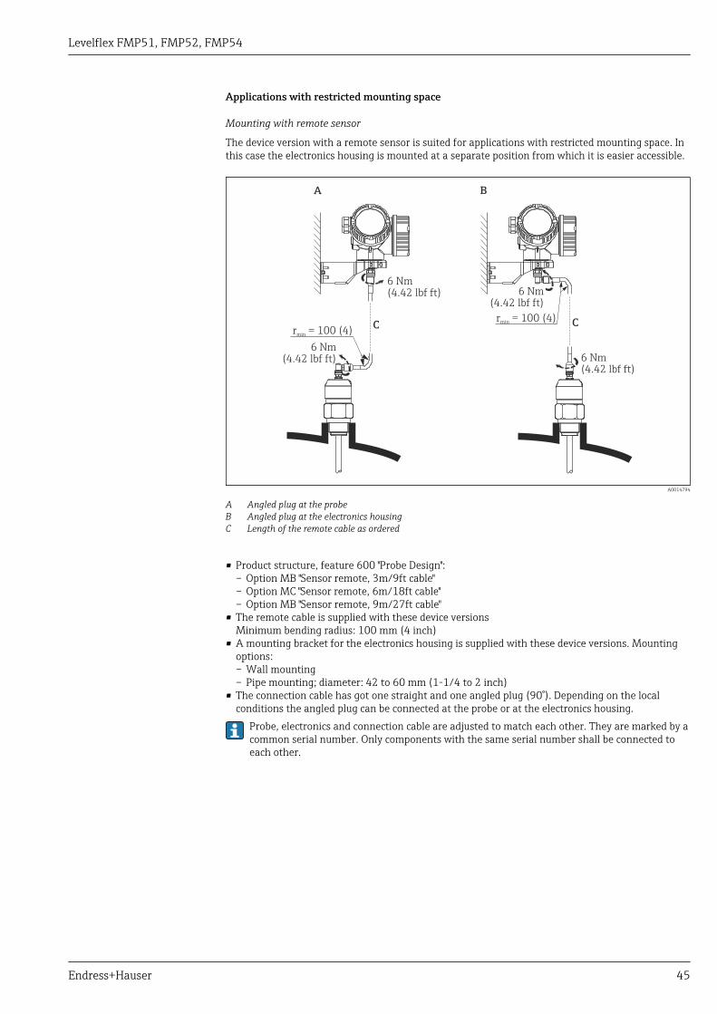
Applications with restricted mounting space
Mounting with remote sensor
The device version with a remote sensor is suited for applications with restricted mounting space. Inthis case the electronics housing is mounted at a separate position from which it is easier accessible.
A B
6 Nm(4.42 lbf ft)
6 Nm(4.42 lbf ft) 6 Nm
(4.42 lbf ft)
C C
6 Nm(4.42 lbf ft)
r = 100 (4)min
r = 100 (4)min
A0014794
A Angled plug at the probeB Angled plug at the electronics housingC Length of the remote cable as ordered
• Product structure, feature 600 "Probe Design":– Option MB "Sensor remote, 3m/9ft cable"– Option MC "Sensor remote, 6m/18ft cable"– Option MB "Sensor remote, 9m/27ft cable"
• The remote cable is supplied with these device versionsMinimum bending radius: 100 mm (4 inch)
• A mounting bracket for the electronics housing is supplied with these device versions. Mountingoptions:– Wall mounting– Pipe mounting; diameter: 42 to 60 mm (1-1/4 to 2 inch)
• The connection cable has got one straight and one angled plug (90°). Depending on the localconditions the angled plug can be connected at the probe or at the electronics housing.
Probe, electronics and connection cable are adjusted to match each other. They are marked by acommon serial number. Only components with the same serial number shall be connected toeach other.
Levelflex FMP51, FMP52, FMP54
46 Endress+Hauser
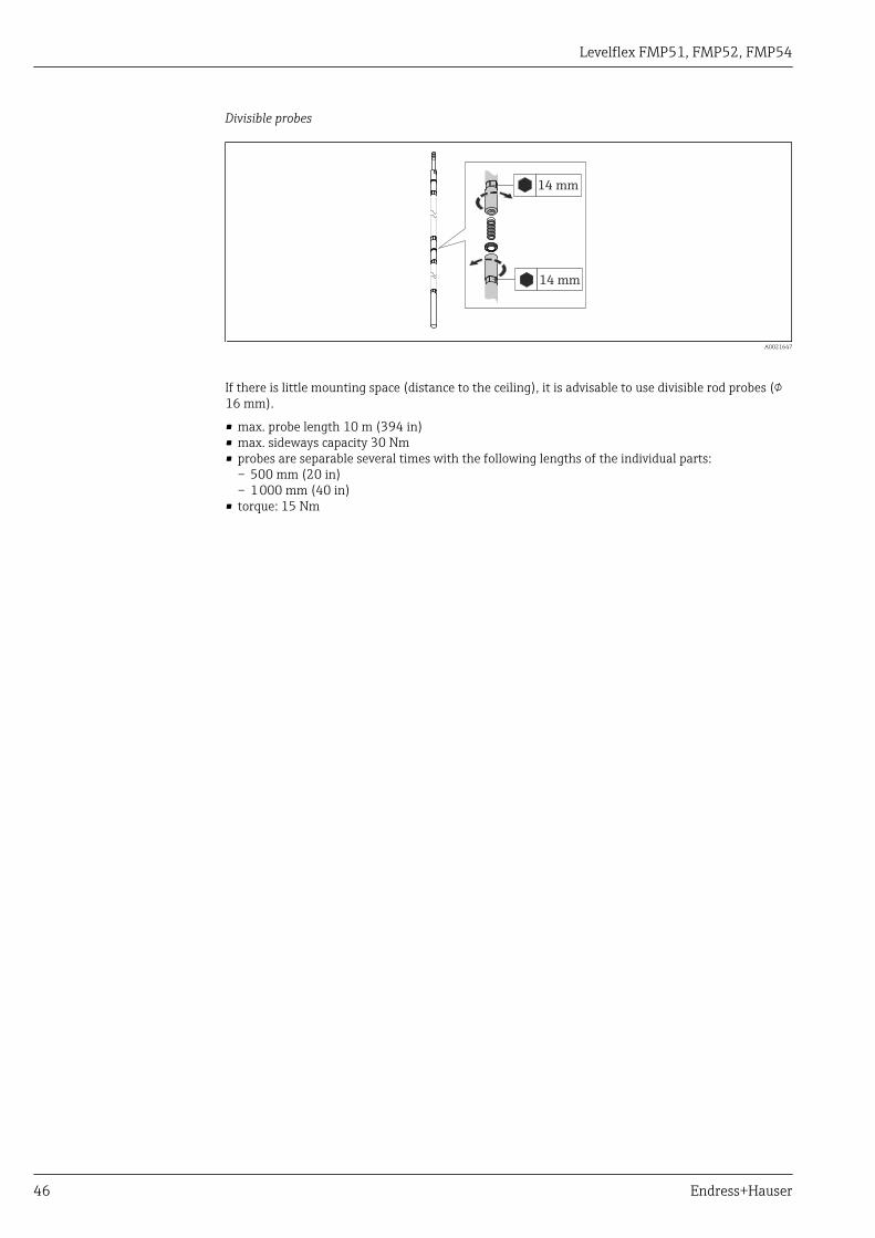
Divisible probes
14 mm
14 mm
A0021647
If there is little mounting space (distance to the ceiling), it is advisable to use divisible rod probes (16 mm).
• max. probe length 10 m (394 in)• max. sideways capacity 30 Nm• probes are separable several times with the following lengths of the individual parts:
– 500 mm (20 in)– 1 000 mm (40 in)
• torque: 15 Nm

Levelflex FMP51, FMP52, FMP54
Endress+Hauser 47
Notes on the mechanical load of the probe
Tensile load limit of rope probes
Sensor Feature 060 Probe Tensile load limit [kN]
FMP51 LA, LBMB, MD
Rope 4mm (1/6") 316 5
FMP52 OA, OB, OC, OD Rope 4mm (1/6") PFA>316 2
FMP54 LA, LB Rope 4mm (1/6") 316 10
Bending strength of rod probes
Sensor Feature 060 Probe Bending strength [Nm]
FMP51 AA, AB Rod 8mm (1/3") 316L 10
AC, AD Rod 12mm (1/2") 316L 30
AL, AM Rod 12mm (1/2") AlloyC 30
BA, BB, BC, BD Rod 16mm (0.63") 316L divisible 30
FMP52 CA, CB Rod 16mm (0.63") PFA>316L 30
FMP54 AE, AF Rod 16mm (0.63") 316L 30
BA, BB, BC, BD Rod 16mm (0.63") 316L divisible 30
Bending load (torque) through fluid flow
The formula for calculating the bending torque M impacting on the probe:
M = cw ⋅ ρ/2 ⋅ v2 ⋅ d ⋅ L ⋅ (LN - 0.5 ⋅ L)
with:
cw: Friction factor
ρ [kg/m3]: Density of the medium
v [m/s]: Velocity of the medium perpendicular to the probe rod
d [m]: Diameter of the probe rod
L [m]: Level
LN [m]: Probe length
Calculation example
v
LN
L
d
A0014175
Friction factor cw 0,9 (on the assumption of a turbulent current - highReynolds number)
Density ρ [kg/m3] 1000 (e.g. water)
Probe diameter d [m] 0,008
L = LN (worst case)

Levelflex FMP51, FMP52, FMP54
48 Endress+Hauser
Bending torque [M] on rod probes, diameter 8mm (1/3”)
Probe length [ ] in metersLN
v=0.5m/s
v=0.7m/s
v=1.0m/s
ma
x.
be
nd
ing
torq
ue
0.4 0.8 1.2 1.6 2 2.4 2.8 3.2 3.6 4
0.0
2.0
4.0
6.0
8.0
10.0
12.0
14.0
16.0
18.0
20.0
Be
nd
ing
[Nm
]to
rque
A0014182-EN
Bending strength of coax probes
Sensor Feature 060 Process connection Probe Bending strength[Nm]
FMP51 UA, UB Thread G¾ oder NPT¾ Coax 316L, Ø 21,3mm
60
• Thread G1½ orNPT1½
• Flange
Coax 316L, Ø 42,4mm
300
UC, UD Flange Coax AlloyC, Ø42,4 mm
300
FMP54 UA, UB • Thread G1½ orNPT1½
• Flange
Coax 316L, Ø 42,4mm
300

Levelflex FMP51, FMP52, FMP54
Endress+Hauser 49
Notes on the process connection
Probes are mounted to the process connection with threaded connections or flanges. If during thisinstallation there is the danger that the probe end moves so much that it touches the tank floor orcone at times, the probe must, if necessary, be shortened and fixed down → 55.
Threaded connection
A0015121
19 Mounting with threaded connection; flush with the container ceiling
Seal
The thread as well as the type of seal comply to DIN 3852 Part 1, screwed plug form A.
They can be sealed with the following types of sealing rings:• Thread G3/4": According to DIN 7603 with the dimensions 27 x 32 mm• Thread G1-1/2": According to DIN 7603 with the dimensions 48 x 55 mmPlease use a sealing ring according to this standard in the form A, C or D and of a material that isresistant to the application.
For the length of the screwed plug refer to the dimensional drawing:• FMP51: → 80• FMP54: → 83

Levelflex FMP51, FMP52, FMP54
50 Endress+Hauser
Nozzle mounting
£1
50
(6
)
H
ø 150 (6)£
A0015122
• Permissible nozzle diameter: ≤ 150 mm (6 in).For larger diameters the near range measuring capability may be reduced.For nozzles ≥ DN300: → 53.
• Permissible nozzle height 7): ≤ 150 mm (6 in).For a larger height the near range measuring capability may be reduced.Larger nozzle heights may be possible in special cases (see sections "Center rod for FMP51 andFMP52" and "Rod extension/centering HMP40 for FMP54").
• The end of the nozzle should be flush with the tank ceiling in order to avoid ringing effects.With thermally insulated vessels the nozzle should also be insulated in order to preventcondensate formation.
7) Larger nozzle heights on request

Levelflex FMP51, FMP52, FMP54
Endress+Hauser 51
Center rod for FMP51 and FMP52
For rope probes it may be necessary to use a version with center rod in order to prevent the proberod from coming into contact with the nozzle wall. Probes with center rod are available for FMP51and FMP52.
Probe Max. nozzle height (= length of the center rod) Option to be selected in feature 060 ("Probe")
FMP51 150 mm LA
6 inch LB
300 mm MB
12 inch MD
FMP52 150 mm OA
6 inch OC
300 mm OB
12 inch OD

Levelflex FMP51, FMP52, FMP54
52 Endress+Hauser
Rod extension/centering HMP40 for FMP54
For FMP54 with rope probes the rod extension/centering HMP 40 is available as an accessory→ 117. It has to be used if otherwise the probe rope comes into contact with the lower edge ofthe nozzle.
For FMP54 with rope probes the rod extension/centering HMP 40 is available as an accessory. It hasto be used if otherwise the probe rope comes into contact with the lower edge of the nozzle.
This accessory consists of the extension rod corresponding to the nozzle height, on which acentering disk is also mounted if the nozzles are narrow or when working in bulk solids. Thiscomponent is delivered separately from the device. Please order the probe lengthcorrespondingly shorter.
Centering disks with small diameters (DN40 and DN50) may only be used if there is nosignificant build-up in the nozzle above the disk. The nozzle must not become clogged by theproduct.

Levelflex FMP51, FMP52, FMP54
Endress+Hauser 53
Installation in nozzles ≥ DN300
If installation in ≥ 300mm/12" nozzles is unavoidable, installation must be carried out in accordancewith the following sketch.
1
2
3
4
A0014199
1 Lower edge of the nozzle2 Approx. flush with the lower edge of the nozzle (± 50 mm/2")3 Plate4 Pipe 150 to 180 mm (6 to 7 inch)
Nozzle diameter Plate diameter
300 mm (12") 280 mm (11")
≥ 400 mm (16") ≥ 350 mm (14")

Levelflex FMP51, FMP52, FMP54
54 Endress+Hauser
Mounting cladded flanges
For cladded flanges of FMP52, observe the following:• Use flange screws according to the number of flange holes.• Tighten the screws with the required torque (see table).• Retighten the screws after 24 hours or after the first temperature cycle.• Depending on process pressure and process temperature check and retighten the screws at
regular intervals.Usually, the PTFE flange cladding also serves as a seal between the nozzle and the deviceflange.
Flange size Number of screws Recommended torque [Nm]
minimum maximum
EN
DN40/PN40 4 35 55
DN50/PN16 4 45 65
DN50/PN40 4 45 65
DN80/PN16 8 40 55
DN80/PN40 8 40 55
DN100/PN16 8 40 60
DN100/PN40 8 55 80
DN150/PN16 8 75 115
DN150/PN40 8 95 145
ASME
1½"/150lbs 4 20 30
1½"/300lbs 4 30 40
2"/150lbs 4 40 55
2"/300lbs 8 20 30
3"/150lbs 4 65 95
3"/300lbs 8 40 55
4"/150lbs 8 45 70
4"/300lbs 8 55 80
6"/150lbs 8 85 125
6"/300lbs 12 60 90
JIS
10K 40A 4 30 45
10K 50A 4 40 60
10K 80A 8 25 35
10K 100A 8 35 55
10K 100A 8 75 115

Levelflex FMP51, FMP52, FMP54
Endress+Hauser 55
Securing the probe
Securing rope probes
1
A
C
B
2
A0012609
A Sag of the rope: ≥ 1 cm per 1m of the probe length (0.12 inch per 1 ft of the probe length)B Reliably grounded end of probeC Reliably isolated end of probe1: Mounting and contact with a bolt2 Mounting kit isolated
• The end of the probe needs to be secured under the following conditions:if otherwise the probe sporadically comes into contact with the wall of the vessel, the outlet cone,internal fittings or other parts of the installation.
• The end of probe can be secured at its internal threadrope 4 mm (1/6"), 316: M 14
• The fixing must be either reliably grounded or reliably insulated. If it is not possible to mount theprobe weight with a reliably insulated connection, it can be secured using an isolated eyelet, whichis available as an accessory.
• In order to prevent an extremely high tensile load (e.g. due to thermal expansion) and the risk ofrope crack, the rope has to be slack. Make the rope longer than the required measuring range suchthat there is a sag in the middle of the rope that is ≥ 1cm/(1 m rope length) [0.12 inch/(1 ft ropelength)].Tensile load limit of rope probes: → 47
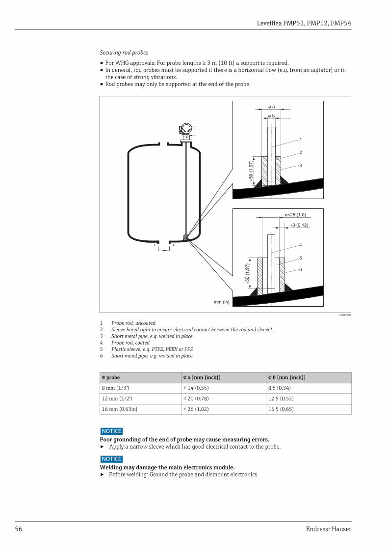
Levelflex FMP51, FMP52, FMP54
56 Endress+Hauser
Securing rod probes
• For WHG approvals: For probe lengths ≥ 3 m (10 ft) a support is required.• In general, rod probes must be supported if there is a horizontal flow (e.g. from an agitator) or in
the case of strong vibrations.• Rod probes may only be supported at the end of the probe.
mm (in)
ø a
ø b
»50
(1
.97
)
1
2
3
»50 (
1.9
7)
4
5
6
ø<25 (1.0)
3 (0.12)»
A0012607
1 Probe rod, uncoated2 Sleeve bored tight to ensure electrical contact between the rod and sleeve!3 Short metal pipe, e.g. welded in place4 Probe rod, coated5 Plastic sleeve, e.g. PTFE, PEEK or PPS6 Short metal pipe, e.g. welded in place
probe a [mm (inch)] b [mm (inch)]
8 mm (1/3") < 14 (0.55) 8.5 (0.34)
12 mm (1/2") < 20 (0.78) 12.5 (0.52)
16 mm (0.63in) < 26 (1.02) 16.5 (0.65)
NOTICEPoor grounding of the end of probe may cause measuring errors.‣ Apply a narrow sleeve which has good electrical contact to the probe.
NOTICEWelding may damage the main electronics module.‣ Before welding: Ground the probe and dismount electronics.
Levelflex FMP51, FMP52, FMP54
Endress+Hauser 57
Securing coax probes
For WHG approvals: For probe lengths ≥ 3 m (10 ft) a support is required.
A0012608
Coax probes can be supported at any point of the outer tube.
Levelflex FMP51, FMP52, FMP54
58 Endress+Hauser
Special mounting conditions
Bypasses and stilling wells
In bypass and stilling well applications it is recommended to use a centering disks or stars.
A B
³1
00
(3.9
4)
øD
ød
ød
1
2
2
3
C
³1
00
(3.9
4)
4
A0012615
20 Dimensions: mm (in)
A Mounting in a stilling wellB Mounting in a bypassC Center washer or centering star1 Metallic center washer (316L) for level measurement2 Fixing screw; torque: 25 Nm ± 5 Nm3 Non-metallic centering star (PEEK, PFA) for interface measurement4 Minimum distance between end of probe and lower edge of the bypass; see table below
Allocation of probe type and center washer or centering star to pipe diameter
Feature 610 - Accessory mounted
Application Option Type of probeCenter washerCentering star
Pipe
d [mm (in)] Material D [mm (in)]
Level measurement OA Rod probe 75 (2,95) 316L DN80/3" to DN100/4"
OB Rod probe 45 (1,77) 316L DN50/2" to DN65/2½"
OC Rope probe 75 (2,95) 316L DN80/3" to DN100/4"
Interface measurement OD Rod probe 48...95 (1,89...3,74) PEEK ≥ 50 mm (2")
OE Rod probe 37 (1,46) PFA ≥ 40 mm (1.57")
Minimum distance between end of probe and lower edge of the bypass
Type of probe Minimum distance
Rope 150 mm (6 in)
Rod 10 mm (0.4 in)
Coax 10 mm (0.4 in)
Levelflex FMP51, FMP52, FMP54
Endress+Hauser 59
• Pipe diameter: > 40 mm (1.6") for rod probes• Rod probe installation can take place up to a diameter size of 150 mm (6 in). In the event of larger
diameters, a coax probe is recommended.• Side disposals, holes or slits and welded joints that protrude up to approx. 5 mm (0.2") inwards do
not influence the measurement.• The pipe may not exhibit any steps in diameter.• The probe must be 100 mm longer than the lower disposal.• Within the measuring range, the probe must not get into contact with the pipe wall. If necessary,
secure the probe by retaining or tensioning. All rope probes are prepared for tensioning incontainers (tensioning weight with anchor hole).
• If a metallic center washer is mounted at the end of the probe, it enables a reliable recognition ofthe end-of-probe signal (see feature 610 of the product structure).Note: For interface measurements only use the nonmetallic centering star made of PEEK or PFA(feature 610, options OD or OE).
• Coax probes can always be applied if there is enough mounting space.For bypasses with condensate formation (water) and a medium with low dielectric constant(e.g. hydrocarbons):
In the course of time the bypass is filled with condensate up to the lower disposal and for lowlevels the the level echo is superimposed by the condensate echo. Thus in this range thecondensate level is measured instead of the correct level. Only higher levels are measuredcorrectly. To prevent this, position the lower disposal 100 mm (4 in) below the lowest level tobe measured and apply a metallic centering disk at the height of the lower edge of the lowerdisposal.With heat insulated tanks the bypass should also be insulated in order to prevent condensateformation.For information on bypass solutions from Endress+Hauser please contact your Endress+Hausersales representative.

Levelflex FMP51, FMP52, FMP54
60 Endress+Hauser
Installation in horizontal and upright cylindrical tanks
1
2
A0014141
• Any distance from wall, as long as occasional contact is prevented.• When installing in tanks with a lot of internals or internals situated close to the probe: use a coax
probe.

Levelflex FMP51, FMP52, FMP54
Endress+Hauser 61
Underground tanks
A0014142
Use a coax probe for nozzles with large diameters in order to avoid reflections at the nozzle wall.

Levelflex FMP51, FMP52, FMP54
62 Endress+Hauser
Installation at an angle
a
LN
A0014145
• For mechanical reasons, the probe should be installed as vertically as possible.• With inclined installations the probe length has to be adjusted in dependence to the installation
angle.– Up to LN = 1 m (3.3 ft): α = 30°– Up to LN = 2 m (6.6 ft): α = 10°– Up to LN = 4 m (13.1 ft): α = 5°

Levelflex FMP51, FMP52, FMP54
Endress+Hauser 63
Non-metallic vessels
1
2
A0012527
1 Non-metallic vessel2 Metal sheet or metal flange
To ensure reliable measurements in non-metallic vessels:• Select an instrument version with metal flange (minimum size DN50/2").• Or: mount a metal sheet with a diameter of at least 200 mm (8 in) to the probe at the process
connection. Its orientation must be perpendicular to the probe.A metallic surface is not required for coax probes.

Levelflex FMP51, FMP52, FMP54
64 Endress+Hauser
Plastic or glass tanks: Mounting the probe externally at the wall
1
2
a
3
A0014150
1 Plastic or glass tank2 Metall sheet with threaded sleeve3 No free space between tank wall and probe!
Requirements• The dielectric constant of the medium must be at least DC > 7.• The tank wall must be non-conductvie.• Maximum wall thickness (a):
– Plastic: < 15 mm (0.6")– Glass: < 10 mm (0.4")
• There may be no metallic reinforcements fixed to the tank.Mounting conditions:• The probe must be mounted directly to the tank wall (no open space)• A plastic half pipe with a diameter of approx. 200 mm (8"), or some other protective unit, must be
affixed externally to the probe to prevent any influences on the measurement.• If the tank diameter is less than 300 mm (12"):
A metallic grounding sheet must be installed at the opposite side of the tank. The sheet must beconductively connected to the process connection and cover about the half of the vessel'scircumference.
• If the tank diameter exceeds 300 mm (12"):A metal sheet with a diameter of at least 200 mm (8") must be mounted to the probe at theprocess connection. Its orientation must be perpendicular to the probe (see above).

Levelflex FMP51, FMP52, FMP54
Endress+Hauser 65
Vessels with heat insulation
If process temperatures are high, the device must be included in normal tank insulation toprevent the electronics heating up as a result of heat radiation or convection. The insulationmay not exceed beyond the points labeled "MAX" in the drawings.
MAX1
3
MAX
2
A0014653
21 Process connection with thread - FMP51
1 Tank insulation2 Compact device3 Sensor remote (feature 600)
40
(1
.57
)
40
(1
.57
)
MAX
mm (in)
MAX1
32
A0014654
22 Process connection with flange - FMP51, FMP52
1 Tank insulation2 Compact device3 Sensor remote (feature 600)
XT 280 °C (536 °F)* HT 450 °C (842 °F)
MAX MAXMAX MAX1 1
3
3
2
2
A0014657
23 Process connection with thread - FMP54, sensor version XT and HT
1 Tank insulation2 Compact device3 Sensor remote (feature 600)* The XT version is not recommended for saturated steam above 200 °C (392 °F). Use the HT version instead.
Levelflex FMP51, FMP52, FMP54
66 Endress+Hauser
MAX MAXMAX MAX
XT 280 °C (536 °F)* HT 450 °C (842 °F)
1 1
3
3
2
2
A0014658
24 Process connection with flange - FMP54, sensor version XT and HT
1 Tank insulation2 Compact device3 Sensor remote (feature 600)* The XT version is not recommended for saturated steam above 200 °C (392 °F). Use the HT version instead.

Levelflex FMP51, FMP52, FMP54
Endress+Hauser 67
Replacing a displacer system in an existing displacer chamber
FMP51 and FMP54 are a perfect replacement for a conventional displacer system in an existingdisplacer chamber. Endress+Hauser offers flanges that suit Fischer and Masoneilan displacerchamber for this purpose (special product for FMP51; feature 100, options LNJ, LPJ, LQJ for FMP54).Thanks to menu-guided local operation, commissioning the Levelflex only takes a few minutes.Replacement is also possible when partially filled, and wet calibration is not required.
Your benefits:• No moving parts, thus zero-maintenance operation.• Not sensitive to process influences such as temperature, density, turbulence and vibrations.• The rod probes can be shortened or replaced easily. In this way, the probe can be easily adjusted on
site.
1
A0014153
1 Flange of the displacer chamber
Planning instructions:• In normal cases, use a rod probe. When installing into a metallic displacer chamber up to 150 mm,
you have all the advantages of a coax probe.• It must be ensured that the probe does not come into contact with the side wall. Where necessary,
use a center washer or centering star at the lower end of the probe (feature 610 of the productstructure).
• The center washer or centering star must be adapted as accurately as possible to the internaldiameter of the displacer chamber to also ensure perfect operation in the area of the probe end.
Additional information on interface measurement• In the case of oil and water the centering disk or centering star should be positioned at the lower
edge of the lower disposal (water level).• The pipe may not exhibit any steps in diameter. Use the coax probe where necessary.• In the case of rod probes, it must be ensured that the probe does not come into contact with the
wall. If necessary, use a center washer or centering star at the end of the probe.• A plastic centering star has to be used for interface measurement (feature 610, options OD and
OE).

Levelflex FMP51, FMP52, FMP54
68 Endress+Hauser
Operating conditions: Environment
Ambient temperature range Measuring device –40 to +80 °C (–40 to +176 °F)
Local display –20 to +70 °C (–4 to +158 °F), the readability of the display may be impaired attemperatures outside the temperature range.
Connection cable (for"Probe Design" = "Sensorremote")
max. 100 °C (212 °F)
Remote display FHX50 –40 to 80 °C (–40 to 176 °F)
When operating the device in the open with strong sunlight:• Mount the device in a shady position.• Avoid direct sunlight, especially in warmer regions.• Use a weather protection cover (see accessories).
Ambient temperature limits The following diagrams take into account only function requirements. There may be furtherrestrictions for certified device versions. Please refere to the separate Safety Instructions → 126.
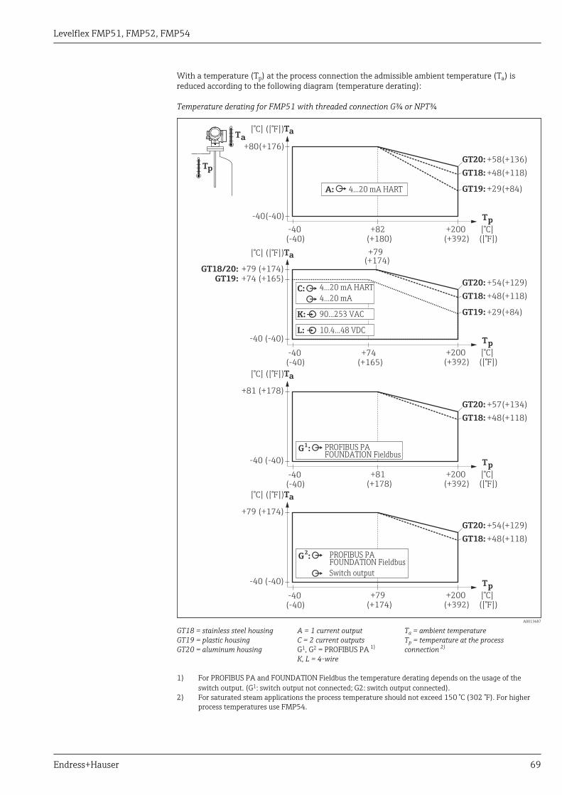
Levelflex FMP51, FMP52, FMP54
Endress+Hauser 69
With a temperature (Tp) at the process connection the admissible ambient temperature (Ta) isreduced according to the following diagram (temperature derating):
Temperature derating for FMP51 with threaded connection G¾ or NPT¾
[°C] ([°F])Ta
[°C] ([°F])Ta
[°C] ([°F])Ta
[°C] ([°F])Ta
[°C]
[°C]
[°C]
[°C]
([°F])
([°F])
([°F])
([°F])
T
T
T
T
p
p
p
p+200
+200
+200
+200
(+392)
(+392)
(+392)
(+392)
+82(+180)
+79(+174)
+74(+165)
-40
-40
-40
-40
(-40)
(-40)
(-40)
(-40)
GT20: +58(+136)
GT20: +54(+129)
GT18: +48(+118)
GT18: +48(+118)
GT19: +29(+84)
GT19: +29(+84)
+80(+176)
GT18/20: +79 (+174)GT19: +74 (+165)
-40(-40)
-40 (-40)
-40 (-40)
-40 (-40)
Ta
Tp
4...20 mA HARTA:
4...20 mA HART
4...20 mAC:
90...253 VACK:
10.4...48 VDCL:
GT20: +57(+134)
GT18: +48(+118)
+81 (+178)
+79(+174)
GT20: +54(+129)
GT18: +48(+118)
+79 (+174)
PROFIBUS PAFOUNDATION Fieldbus
Switch output
G :2
+81(+178)
PROFIBUS PAFOUNDATION Fieldbus
G :1
A0013687
GT18 = stainless steel housingGT19 = plastic housingGT20 = aluminum housing
A = 1 current outputC = 2 current outputsG1, G2 = PROFIBUS PA 1)
K, L = 4-wire
Ta = ambient temperatureTp = temperature at the processconnection 2)
1) For PROFIBUS PA and FOUNDATION Fieldbus the temperature derating depends on the usage of theswitch output. (G1: switch output not connected; G2: switch output connected).
2) For saturated steam applications the process temperature should not exceed 150 °C (302 °F). For higherprocess temperatures use FMP54.

Levelflex FMP51, FMP52, FMP54
70 Endress+Hauser
Temperature derating for FMP51 with threaded connection G1½ or NPT1½
[°C] ([°F])Ta
[°C] ([°F])Ta
[°C] ([°F])Ta
[°C] ([°F])Ta
[°C]
[°C]
[°C]
[°C]
([°F])
([°F])
([°F])
([°F])
T
T
T
T
p
p
p
p+200
+200
+200
+200
(+392)
(+392)
(+392)
(+392)
+82(+180)
+79(+174)
+74(+165)
-40
-40
-40
-40
(-40)
(-40)
(-40)
(-40)
GT20: +57(+135)
GT20: +54(+129)
GT18: +49(+120)
GT18: +49(+120)
GT19: +20(+68)
GT19: +20(+68)
+80(+176)
GT18/20: +79 (+174)GT19: +74 (+165)
-40(-40)
-40 (-40)
-40 (-40)
-40 (-40)
Ta
Tp
4...20 mA HARTA:
4...20 mA HART
4...20 mAC:
90...253 VACK:
10.4...48 VDCL:
GT20: +57(+134)
GT18: +49(+120)
+81 (+178)
+79(+174)
GT20: +54(+129)
GT18: +49(+120)
+79 (+174)
PROFIBUS PAFOUNDATION Fieldbus
Switch output
G :2
+81(+178)
PROFIBUS PAFOUNDATION Fieldbus
G :1
A0014121
GT18 = stainless steel housingGT19 = plastic housingGT20 = aluminum housing
A = 1 current outputC = 2 current outputsG1, G2 = PROFIBUS PA 1)
K, L = 4-wire
Ta = ambient temperatureTp = temperature at the processconnection 2)
1) For PROFIBUS PA and FOUNDATION Fieldbus the temperature derating depends on the usage of theswitch output. (G1: switch output not connected; G2: switch output connected).
2) For saturated steam applications the process temperature should not exceed 150 °C (302 °F). For higherprocess temperatures use FMP54.

Levelflex FMP51, FMP52, FMP54
Endress+Hauser 71
Temperature derating for FMP51 with flange
[°C] ([°F])Ta
[°C] ([°F])Ta
[°C] ([°F])Ta
[°C] ([°F])Ta
[°C]
[°C]
[°C]
[°C]
([°F])
([°F])
([°F])
([°F])
T
T
T
T
p
p
p
p+200
+200
+200
+200
(+392)
(+392)
(+392)
(+392)
+82(+180)
+79(+174)
+74(+165)
-40
-40
-40
-40
(-40)
(-40)
(-40)
(-40)
GT20: +59(+138)
GT20: +55(+131)
GT18: +53(+127)
GT18: +51(+124)
GT19: +33(+91)
GT19: +33(+91)
+80(+176)
GT18/20: +79 (+174)GT19: +74 (+165)
-40(-40)
-40 (-40)
-40 (-40)
-40 (-40)
Ta
Tp
4...20 mA HARTA:
4...20 mA HART
4...20 mAC:
90...253 VACK:
10.4...48 VDCL:
GT20: +58(+136)
GT18: +53(+127)
+81 (+178)
+79(+174)
GT20: +55(+131)
GT18: +51(+124)
+79 (+174)
PROFIBUS PAFOUNDATION Fieldbus
Switch output
G :2
+81(+178)
PROFIBUS PAFOUNDATION Fieldbus
G :1
A0013689
GT18 = stainless steel housingGT19 = plastic housingGT20 = aluminum housing
A = 1 current outputC = 2 current outputsG1, G2 = PROFIBUS PA 1)
K, L = 4-wire
Ta = ambient temperatureTp = temperature at the processconnection 2)
1) For PROFIBUS PA and FOUNDATION Fieldbus the temperature derating depends on the usage of theswitch output. (G1: switch output not connected; G2: switch output connected).
2) For saturated steam applications the process temperature should not exceed 150 °C (302 °F). For higherprocess temperatures use FMP54.

Levelflex FMP51, FMP52, FMP54
72 Endress+Hauser
Temperature derating for FMP52
[°C] ([°F])Ta
[°C] ([°F])Ta
[°C] ([°F])Ta
[°C] ([°F])Ta
[°C]
[°C]
[°C]
[°C]
([°F])
([°F])
([°F])
([°F])
T
T
T
T
p
p
p
p
+200
+200
+200
+200
(+392)
(+392)
(+392)
(+392)
+82
+74
(+180)
(+165)
+79(+174)
-50
-50
-50
-50
-40
-40
-40
-40
(-58)
(-58)
(-58)
(-58)
(-40)
(-40)
(-40)
(-40)
GT20:
GT20:
GT20:
GT19:
GT19:
+60(+140)
+56(+133)
+56(+133)
-36(-33)
-36(-33)
GT18:
GT18:
GT18:
GT18:
GT18:
GT18:
GT18:
+53(+127)
+51(+124)
+51(+124)
-37(-35)
-37(-35)
-37(-35)
-37(-35)
GT19:
GT19:
GT20:
GT20:
GT20:
GT20:
+38(+100)
+38(+100)
-38(-36)
-38(-36)
-38(-36)
-38(-36)
+80(+176)
+79(+174)
+81(+178)
GT18/20: +79 (+174)GT19: +74 (+165)
-40(-40)
-40(-40)
-40(-40)
-40(-40)
Ta
Tp
4...20 mA HARTA:
4...20 mA HART
4...20 mAC:
90...253 VACK:
10.4...48 VDCL:
GT20: +59(+138)
GT18: +53(+127)
+79
+81
(+174)
(+178)
PROFIBUS PAFOUNDATION Fieldbus
Switch output
G :2
PROFIBUS PAFOUNDATION Fieldbus
G :1
A0013633
GT18 = stainless steel housingGT19 = plastic housingGT20 = aluminum housing
A = 1 current outputC = 2 current outputsG1, G2 = PROFIBUS PA 1)
K, L = 4-wire
Ta = ambient temperatureTp = temperature at the processconnection 2)
1) For PROFIBUS PA and FOUNDATION Fieldbus the temperature derating depends on the usage of theswitch output. (G1: switch output not connected; G2: switch output connected).
2) For saturated steam applications the process temperature should not exceed 150 °C (302 °F). For higherprocess temperatures use FMP54.

Levelflex FMP51, FMP52, FMP54
Endress+Hauser 73
Temperature derating for FMP54 - version XT up to +280 °C (+536 °F )
-196
-196
-196
-196
(-321)
(-321)
(-321)
(-321)
[°C] ([°F])Ta
[°C] ([°F])Ta
[°C] ([°F])Ta
[°C] ([°F])Ta
[°C]
[°C]
[°C]
[°C]
([°F])
([°F])
([°F])
([°F])
T
T
T
T
p
p
p
p+280
+280
+280
+280
(+536)
(+536)
(+536)
(+536)
+82(+180)
+79(+174)
+74(+165)
-40
-40
-40
-40
(-40)
(-40)
(-40)
(-40)
GT20: +62(+144)
GT20: +59(+138)
GT18: +56(+133)
GT18: +52(+126)
GT19: +42(+108)
GT19: +42(+108)
+80(+176)
GT18/20:
GT19:
GT19:
GT18:
GT18:
GT20:
GT20:
GT20:
GT20:
+79 (+174)
-5(+23)
-5(+23)
-16(+3)
-16(+3)
-23(-9)
-23(-9)
-23(-9)
-23(-9)
GT19:
GT18:
GT18:
+74 (+165)
-16(+3)
-16(+3)
-40(-40)
-40 (-40)
-40 (-40)
-40 (-40)
Ta
Tp
4...20 mA HARTA:
4...20 mA HART
4...20 mAC:
90...253 VACK:
10.4...48 VDCL:
GT20: +61(+142)
GT18: +55(+130)
+81 (+178)
+79(+174)
GT20: +58(+137)GT18: +55(+126)
+79 (+174)
PROFIBUS PAFOUNDATION Fieldbus
Switch output
G :2
+81(+178)
PROFIBUS PAFOUNDATION Fieldbus
G :1
A0013631
GT18 = stainless steel housingGT19 = plastic housingGT20 = aluminum housing
A = 1 current outputC = 2 current outputsG1, G2 = PROFIBUS PA 1)
K, L = 4-wire
Ta = ambient temperatureTp = temperature at the processconnection 2)
1) For PROFIBUS PA and FOUNDATION Fieldbus the temperature derating depends on the usage of theswitch output. (G1: switch output not connected; G2: switch output connected).
2) For saturated steam applications the process temperature should not exceed 200 °C (392 °F). For higherprocess temperatures use the HT version.

Levelflex FMP51, FMP52, FMP54
74 Endress+Hauser
Temperature derating for FMP54 - version HT up to +450 °C (+842 °F )
[°C] ([°F])Ta
[°C] ([°F])Ta
[°C] ([°F])Ta
[°C] ([°F])Ta
[°C]([°F])
Tp
[°C]([°F])
Tp
[°C]([°F])
Tp
[°C]([°F])
Tp
+450
+450
+450
+450
(+842)
(+842)
(+842)
(+842)
+82
+79
+81
+74
(+180)
(+173)
(+178)
(+165)
+79(+174)
-196
-196
-196
-196
-40
-40
-40
-40
(-321)
(-321)
(-321)
(-321)
(-40)
(-40)
(-40)
(-40)
GT20:
GT20:
GT20:
GT19:
GT19:
+56(+133)
+53(+127)
+52(+126)
-22(-8)
-22(-8)
GT18:
GT18:
GT18:
GT18:
GT18:
GT18:
GT18:
+54(+129)
+51(+124)
+50(+123)
-27(-17)
-27(-17)
-27(-16)
-27(-16)
GT19:
GT19:
GT20:
GT20:
GT20:
GT20:
+42(+108)
+38(+100)
-28(-18)
-28(-18)
-28(-18)
-28(-18)
+80(+176)
+79(+174)
+81(+178)
GT18/20: +79 (+174)GT19: +74 (+165)
-40(-40)
-40(-40)
-40(-40)
-40(-40)
Ta
Tp
4...20 mA HARTA:
4...20 mA HART
4...20 mAC:
90...253 VACK:
10.4...48 VDCL:
GT20: +55(+131)
GT18: +53(+127)
PROFIBUS PAFOUNDATION Fieldbus
Switch output
G :2
PROFIBUS PAFOUNDATION Fieldbus
G :1
A0013632
GT18 = stainless steel housingGT19 = plastic housingGT20 = aluminum housing
A = 1 current outputC = 2 current outputsG1, G2 = PROFIBUS PA 1)
K, L = 4-wire
Ta = ambient temperatureTp = temperature at the process connection
1) For PROFIBUS PA and FOUNDATION Fieldbus the temperature derating depends on the usage of theswitch output. (G1: switch output not connected; G2: switch output connected).
Levelflex FMP51, FMP52, FMP54
Endress+Hauser 75
Storage temperature –40 to +80 °C (–40 to +176 °F)
Climate class DIN EN 60068-2-38 (test Z/AD)
Altitude according toIEC61010-1 Ed.3
• Generally up to 2 000 m (6 600 ft) above MSL.• Above 2 000 m (6 600 ft) if the following conditions are met:
– Ordering feature 020 "Power supply; Output" = A, B, C, E or G (2-wire versions)– Supply voltage U < 35 V– Supply voltage of overvoltage category 1
Degree of protection • With closed housing tested according to:– IP68, NEMA6P (24 h at 1.83 m under water surface) 8)
– For plastic housing with transparent cover (display module): IP68 (24 h at 1.00 m under watersurface) 9)
– IP66, NEMA4X• With open housing: IP20, NEMA1• Display module: IP22, NEMA2
Degree of protection IP68 NEMA6P applies for M12 PROFIBUS PA plugs only when thePROFIBUS cable is plugged in and is also rated IP68 NEMA6P.
Vibration resistance DIN EN 60068-2-64 / IEC 60068-2-64: 20 to 2 000 Hz, 1 (m/s2)2/Hz
Cleaning the probe Depending on the application, contamination or buildup can accumulate on the probe. A thin, evenlayer only influences measurement slightly. Thick layers can dampen the signal and then reduce themeasuring range. Severe, uneven buildup, adhesion e.g. through crystallization, can lead to incorrectmeasurement. In this case, we recommend that you use a non-contact measuring principle, or checkthe probe regularly for soiling.
Electromagneticcompatibility (EMC)
Electromagnetic compatibility to all relevant requirements of the EN 61326- series and NAMURrecommendation EMC (NE21). For details see declaration of conformity. 10). If only the analoguesignal is used, unshielded interconnection lines are sufficient for the installation. In case of using thedigital signal (HART/ PA/ FF) use shielded interconnection lines.
Use a shielded cable when working with a digital communications signal.
Max. fluctuations during EMC- tests: < 0.5 % of the span.
When installing the probes in metal and concrete tanks and when using a coax probe:• Interference emission to EN 61326 - x series, electrical equipment Class B.• Interference immunity to EN 61326 - x series, requirements for industrial areas and NAMUR
Recommendation NE 21 (EMC)The measured value can be affected by strong electromagnetic fields when installing rod and ropeprobes without a shielding/metallic wall, e.g. in plastic and wooden silos.• Interference emission to EN 61326 - x series, electrical equipment Class A.• Interference immunity: the measured value can be affected by strong electromagnetic fields.
8) also valid for the "Sensor remote" version9) This restriction is valid if the following options of the product structure have been selected at the same time: 030("Display, Operation") =
C("SD02") or E("SD03"); 040("Housing") = A("GT19").10) Can be downloaded from www.endress.com.
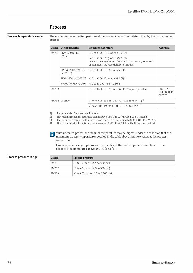
Levelflex FMP51, FMP52, FMP54
76 Endress+Hauser
Process
Process temperature range The maximum permitted temperature at the process connection is determined by the O-ring versionordered:
Device O-ring material Process temperature Approval
FMP51 FKM (Viton GLT37559)
–30 to +150 °C (–22 to +302 °F)
–40 to +150 °C (–40 to +302 °F)only in combination with feature 610 "Accessory Mounted"option model NC "Gas-tight feed through"
EPDM (70C4 pW FKNor E7515)
–40 to +120 °C (–40 to +248 °F)
FFKM (Kalrez 6375) 1) –20 to +200 °C (–4 to +392 °F) 2)
FVMQ (FVMQ 70C79) –50 to 130 °C (–58 to 260 °F)
FMP52 — –50 to +200 °C (–58 to +392 °F); completely coated FDA, 3A,EHEDG, USPCl. VI 3)
FMP54 Graphite Version XT: –196 to +280 °C (–321 to +536 °F) 4)
Version HT: –196 to +450 °C (–321 to +842 °F)
1) Recommended for steam applications2) Not recommended for saturated steam above 150 °C (302 °F). Use FMP54 instead.3) Plastic parts in contact with process have been tested according to USP <88> Class VI-70°C.4) Not recommended for saturated steam above 200 °C (392 °F). Use the HT version instead.
With uncoated probes, the medium temperature may be higher, under the condition that themaximum process temperature specified in the table above is not exceeded at the processconnection.
However, when using rope probes, the stability of the probe rope is reduced by structuralchanges at temperatures above 350 °C (662 °F).
Process pressure range Device Process pressure
FMP51 –1 to 40 bar (–14.5 to 580 psi)
FMP52 –1 to 40 bar (–14.5 to 580 psi)
FMP54 –1 to 400 bar (–14.5 to 5 800 psi)
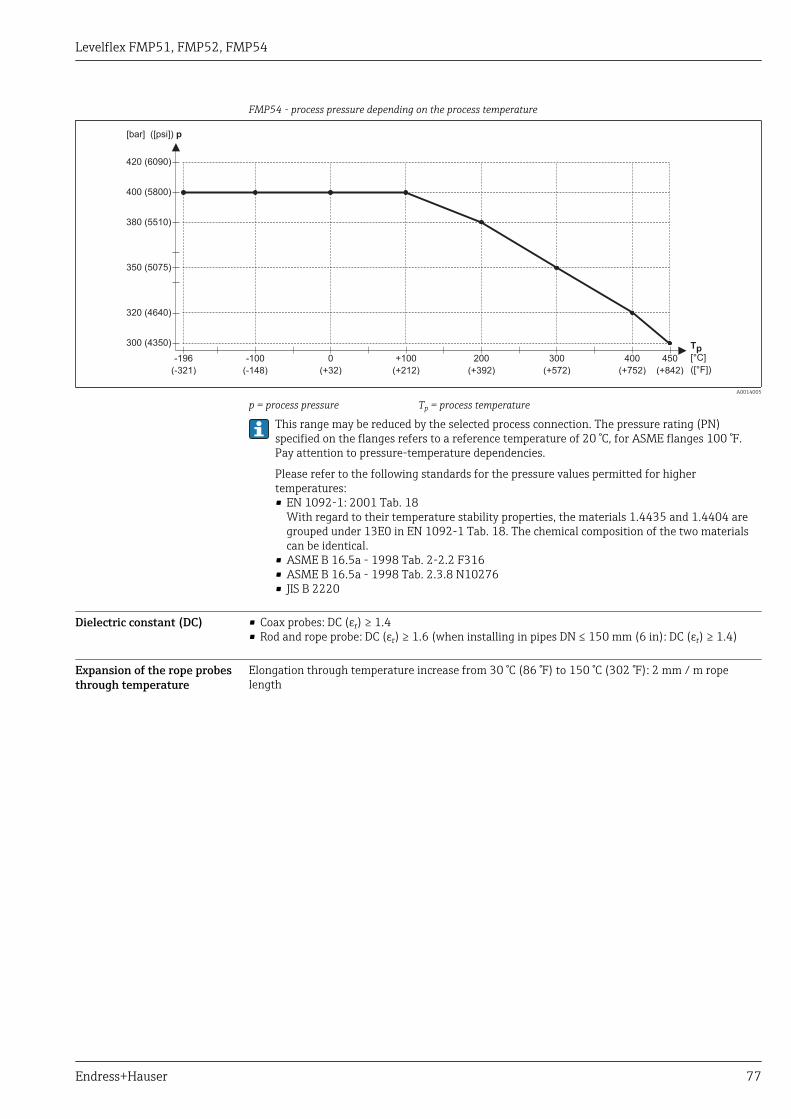
Levelflex FMP51, FMP52, FMP54
Endress+Hauser 77
FMP54 - process pressure depending on the process temperature
[bar] ([psi]) p
[°C]
([°F])
Tp0
(+32)
-100
(-148)
-196
(-321)
+100
(+212)
200
(+392)
300
(+572)
400
(+752)
450
(+842)
300 (4350)
320 (4640)
350 (5075)
380 (5510)
400 (5800)
420 (6090)
A0014005
p = process pressure Tp = process temperature
This range may be reduced by the selected process connection. The pressure rating (PN)specified on the flanges refers to a reference temperature of 20 °C, for ASME flanges 100 °F.Pay attention to pressure-temperature dependencies.
Please refer to the following standards for the pressure values permitted for highertemperatures:• EN 1092-1: 2001 Tab. 18
With regard to their temperature stability properties, the materials 1.4435 and 1.4404 aregrouped under 13E0 in EN 1092-1 Tab. 18. The chemical composition of the two materialscan be identical.
• ASME B 16.5a - 1998 Tab. 2-2.2 F316• ASME B 16.5a - 1998 Tab. 2.3.8 N10276• JIS B 2220
Dielectric constant (DC) • Coax probes: DC (εr) ≥ 1.4• Rod and rope probe: DC (εr) ≥ 1.6 (when installing in pipes DN ≤ 150 mm (6 in): DC (εr) ≥ 1.4)
Expansion of the rope probesthrough temperature
Elongation through temperature increase from 30 °C (86 °F) to 150 °C (302 °F): 2 mm / m ropelength

Levelflex FMP51, FMP52, FMP54
78 Endress+Hauser
Mechanical construction
Dimensions Dimensions of the electronics housing
14
4 (
5.6
7)
14
1.9
(5
.59
)
11
5.2
5 (
4.5
4)
ø1
08
.5 (
4.2
7)
78 (3.07) 90 (3.54)
98 (3.86)*
ø10
3.5
(4
.07
)
R100
A0011666
25 Housing GT18 (316L); Dimensions in mm (in)
*for devices with integrated overvoltage protection.
14
4 (
5.6
7)
13
4.5
(5
.3)
ø1
06
(4
.17
)
78 (3.07) 90 (3.54)
99.5 (3.92)*
ø10
6 (
4.1
7)
R100
A0011346
26 Housing GT19 (Plastics PBT); Dimensions in mm (in)
*for devices with integrated overvoltage protection.
14
4 (
5.6
7)
14
1.5
(5
.57
)
11
7.1
(4
.61
)
ø1
04
.5 (
4.1
1)
ø1
08
.5 (
4.2
7)
78 (3.07) 90 (3.54)
97 (3.82)*
ø10
3.5
(4
.07
)
R100
A0020751
27 Housing GT20 (Alu coated); Dimensions in mm (in)
*for devices with integrated overvoltage protection.
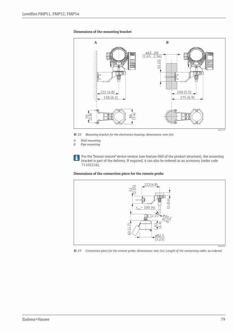
Levelflex FMP51, FMP52, FMP54
Endress+Hauser 79
Dimensions of the mounting bracket
122 (4.8)
52
(2
)
86
(3.4
)
70
(2.8
)140 (5.5)
158 (6.2) 175 (6.9)
A B
ø42...60(1.65...2.36)
A0014793
28 Mounting bracket for the electronics housing: dimensions: mm (in)
A Wall mountingB Pipe mounting
For the "Sensor remote" device version (see feature 060 of the product structure), the mountingbracket is part of the delivery. If required, it can also be ordered as an accessory (order code71102216).
Dimensions of the connection piece for the remote probe
122(4.8)
52
(2.0
5)
15
(0
.6)
61
(2.4
)
ø82.5(3.25)
ø10.2(0.4)
rmin = 100 (4)
43
(1
.7)
A0023856
29 Connection piece for the remote probe; dimensions: mm (in); Length of the connecting cable: as ordered

Levelflex FMP51, FMP52, FMP54
80 Endress+Hauser
FMP51: Dimensions of process connection (G¾,NPT¾) and probe
LN
B
15
0 (
5.9
1)
20
(0
.79
)
ø4 (0.16) ø4 (0.16)ø8 (0.31) ø22 (0.87)
SW7AF7
SW7AF7
SW7AF7
ø22 0( .87)
12
0(.4
7)
ø29 (1.14) 8 (0.31)ø75 (2.95)
M14
FE G H
R
ø10 (0.4)
68
.8(2
.71
)G¾NPT¾
25
(0.9
8)
ø59.35(2.34)
SW36AF36
2 (0.08)
A0012645
30 FMP51: Process connection / probe; dimensions: mm (in). Unit of measurement mm (in)
B Thread ISO G3/4 or ANSI MNPT3/4 (Feature (100)E Rope probe 4mm or 1/6" (Feature 060)F Rope probe 4 mm or 1/6"; centering disk optional (Features 060 and 610)G Rod probe 8mm or 1/3" (Feature 060)H Coax probe (Feature 060)LN Length of probeR Reference point of the measurement

Levelflex FMP51, FMP52, FMP54
Endress+Hauser 81
FMP51: Dimensions of process connection (G1½,NPT1½,flange) and probe
I J L NMK
15
0 (
5.9
1)
ø12 (0.47)
ø16 (0.63)
39
(1.5
4)
50
0 (
19
.7)
10
00
(3
9.4
)2
.2 (
0.0
9)
min
. 5
0 (
1.9
7)
ma
x.
55
1 (
21
.7)
ma
x.
10
51
(4
1.4
)
SW14AF14
SW10AF10
SW14AF14
SW14AF14
SW10AF10
SW10AF10
ø22 0( .87)
ø4 0( .16)ø4 0( .16)
20
(0
.79
)
ø42.41( .67)
ø12 0( .47) ø12 0( .47)
ø42.2 1( .66)*
M14 2 (0.08)2.77 (0.11)
40(
.16
)
P
9 (
0.3
5) PP
12
0(.4
7)
ø29 (1.14)
ø75 (2.95)
LN
R
40
(1.5
7)
Q
78
(3
.1)
78
(3
.1)
78
(3
.1)
G1½ NPT1½
25
(0.9
8)
26
(1.0
2)
ø59.35(2.34)
ø59.35(2.34)
ø59.35(2.34)
SW55AF55
SW55AF55
B DC
ø10 (0.4)
ø10 (0.4)
A0012756
31 FMP51: Process connection / probe; dimensions: mm (in). Unit of measurement mm (in)
B Thread ISO228 G1-1/2 (Feature 100)C Thread ANSI MNPT1-1/2 (Feature 100)D Flange ANSI B16.5, EN1092-1, JIS B2220 (Feature 100)I Rope probe 4mm or 1/6" (Feature 060)J Rope probe 4mm or 1/6"; centering disk optional (Features 060 and 610)K Rod probe 12mm or 1/2"; centering disk optional, see table below (Features 060 and 610)L Rod probe 16 mm or 0.63in, 20" or 40" divisible; centering disk optional, see table below (Feature 060 and
610)M Coax probe; AlloyC (Feature 060)N Coax probe; 316L (Feature 060)LN Length of probeR Reference point of the measurement
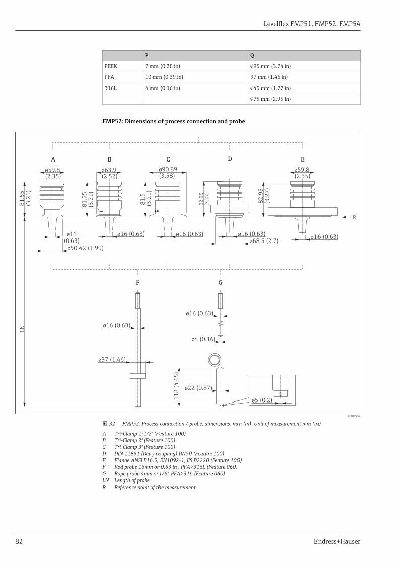
Levelflex FMP51, FMP52, FMP54
82 Endress+Hauser
P Q
PEEK 7 mm (0.28 in) 95 mm (3.74 in)
PFA 10 mm (0.39 in) 37 mm (1.46 in)
316L 4 mm (0.16 in) 45 mm (1.77 in)
75 mm (2.95 in)
FMP52: Dimensions of process connection and probe
F G
ø16 0.63)(
ø16 0.63)(
ø4 0.16)(
ø37 )(1.46
11
8.6
5)
(4
LN
ø22 0.87)(
R
B
81
.55
(3.2
1)
ø63.9(2.52)
ø16 (0.63)
C
81
.5(3
.21
)
ø90.89(3.58)
ø16 (0.63)
E
82
.95
(3.2
7)
ø59.8(2.35)
ø16 (0.63)
D
82
.95
(3.2
7)
ø68.5 (2.7)ø16 (0.63)
A
81
.55
(3.2
1)
ø50.42 (1.99)
ø59.8(2.35)
ø16(0.63)
ø5 (0.2)
A0012757
32 FMP52: Process connection / probe; dimensions: mm (in). Unit of measurement mm (in)
A Tri-Clamp 1-1/2" (Feature 100)B Tri-Clamp 2" (Feature 100)C Tri-Clamp 3" (Feature 100)D DIN 11851 (Dairy coupling) DN50 (Feature 100)E Flange ANSI B16.5, EN1092-1, JIS B2220 (Feature 100)F Rod probe 16mm or 0.63 in , PFA>316L (Feature 060)G Rope probe 4mm or1/6", PFA>316 (Feature 060)LN Length of probeR Reference point of the measurement

Levelflex FMP51, FMP52, FMP54
Endress+Hauser 83
FMP54: Dimensions of process connection and probeL
N
R
A
SW14AF14
SW60AF60
M40x137
(1
.46
)
13
0 (
5.1
2)
8 (
0.3
1)
25
0.9
(9
.88
)
ø90(3.54)
8 (
0.3
1)
B
SW14AF14
M40x1
16
0 (
6.3
)
27
7.9
(1
0.9
)
ø90(3.54)
8 (
0.3
1)
C
SW60AF60
SW14AF14
M40x11
30
(5
.12
)
31
6.6
(1
2.5
)
37
(1
.46
)
ø90(3.54)
8 (
0.3
1)
D
SW14AF14
M40x1
16
0 (
6.3
)
34
1.8
(1
3.5
)
ø90(3.54)
E
SW14AF14
15
0 (
5.9
1)
ø4 (0.16)
M14ø22 (0.87)
20
(0
.79
)
SW14AF14
12
(0
.47
)
4 (
0.1
6)
ø75 (2.95)ø29 (1.14)
ø4 (0.16)
F G
SW14AF14
ø16 (0.63)
M
L
9 (
0.3
5)L
M
H
50
0 (
19
.7)
SW14AF14
SW14AF14
SW14AF14
10
00
(3
9.4
)
2.2
(0
.09
)
ø16 (0.63)
min
. 5
0 (
1.9
7)
ma
x.
10
51
(4
1.4
)
L
M
ø16 (0.63)ø42.4 (1.67)
I
2 (0.08)
A0012778
33 FMP54: Process connection / probe; dimensions: mm (in). Unit of measurement mm (in)
A Thread ISO228 G1-1/2 or ANSI MNPT1-1/2; XT 280 °C (Features 100 and 090)B Flange ANSI B16.5, EN1092-1, JIS B2220; XT 280 °C (Features 100 and 090)C Thread ISO228 G1-1/2 or ANSI MNPT1-1/2; HT 450 °C (Features 100 and 090)D Flange ANSI B16.5, EN1092-1, JIS B2220; HT 450°C (Features 100 and 090)E Rope probe 4mm or 1/6" (Feature 060)F Rope probe 4mm (1/6"), centering disk optional (Features 060 and 610)G Rod probe 16mm or 0.63in; centering disk optional, see table below (Features 060 and 610)H Rod probe 16mm or 0.63in ; 20" or 40" divisible; centering disk optional, see table below (Feature 060 and
610)I Coax probe (Feature 060)LN Length of probeR Reference point of the measurement

Levelflex FMP51, FMP52, FMP54
84 Endress+Hauser
L M
PEEK 7 mm (0.28 in) 95 mm (3.74 in)
PFA 10 mm (3.94 in) 37 mm (1.46 in)
316L 4 mm (0.16 in) 45 mm (1.77 in)
75 mm (2.95 in)
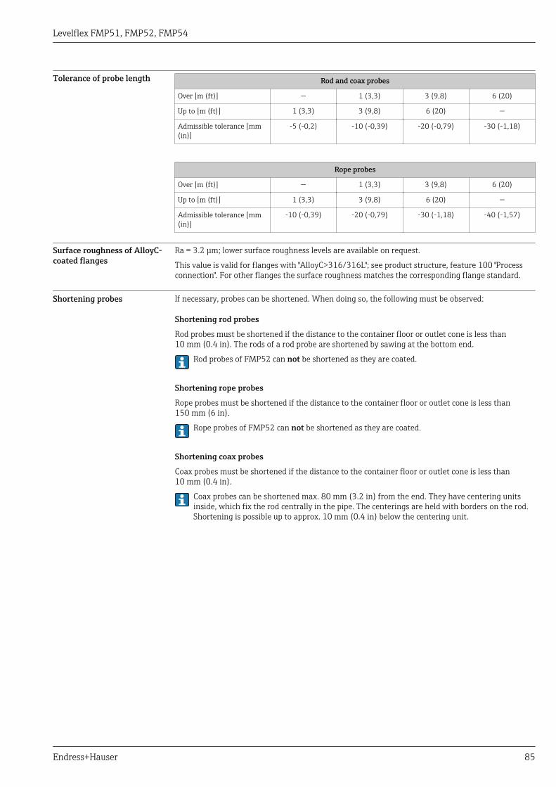
Levelflex FMP51, FMP52, FMP54
Endress+Hauser 85
Tolerance of probe length Rod and coax probes
Over [m (ft)] — 1 (3,3) 3 (9,8) 6 (20)
Up to [m (ft)] 1 (3,3) 3 (9,8) 6 (20) —
Admissible tolerance [mm(in)]
-5 (-0,2) -10 (-0,39) -20 (-0,79) -30 (-1,18)
Rope probes
Over [m (ft)] — 1 (3,3) 3 (9,8) 6 (20)
Up to [m (ft)] 1 (3,3) 3 (9,8) 6 (20) —
Admissible tolerance [mm(in)]
-10 (-0,39) -20 (-0,79) -30 (-1,18) -40 (-1,57)
Surface roughness of AlloyC-coated flanges
Ra = 3.2 μm; lower surface roughness levels are available on request.
This value is valid for flanges with "AlloyC>316/316L"; see product structure, feature 100 "Processconnection". For other flanges the surface roughness matches the corresponding flange standard.
Shortening probes If necessary, probes can be shortened. When doing so, the following must be observed:
Shortening rod probes
Rod probes must be shortened if the distance to the container floor or outlet cone is less than10 mm (0.4 in). The rods of a rod probe are shortened by sawing at the bottom end.
Rod probes of FMP52 can not be shortened as they are coated.
Shortening rope probes
Rope probes must be shortened if the distance to the container floor or outlet cone is less than150 mm (6 in).
Rope probes of FMP52 can not be shortened as they are coated.
Shortening coax probes
Coax probes must be shortened if the distance to the container floor or outlet cone is less than10 mm (0.4 in).
Coax probes can be shortened max. 80 mm (3.2 in) from the end. They have centering unitsinside, which fix the rod centrally in the pipe. The centerings are held with borders on the rod.Shortening is possible up to approx. 10 mm (0.4 in) below the centering unit.

Levelflex FMP51, FMP52, FMP54
86 Endress+Hauser
Weight Housing
Part Weight
Housing GT18 - stainless steel approx. 4.5 kg
Housing GT19 - plastic approx. 1.2 kg
Housing GT20 - aluminium approx. 1.9 kg
FMP51 with threaded connection G¾ or NPT¾
Part Weight Part Weight
Sensor approx. 0.8 kg Rod probe 8 mm approx. 0.4 kg/m probe length
Rope probe 4 mm approx. 0.,1 kg/m probe length Coax probe approx. 1.2 kg/m probe length
FMP51 with threaded connection G1½/NPT1½ or flange
Part Weight Part Weight
Sensor approx. 1.2 kg + weight of flange Rod probe 16 mm approx. 1.1 kg/m probe length
Rope probe 4 mm approx. 0.1 kg/m probe length Coax probe approx. 3.0 kg/m probe length
Rod probe 12 mm approx. 0.9 kg/m probe length
FMP52
Part Weight Part Weight
Sensor approx. 1.2 kg + weight of flange Rope probe 4 mm approx. 0.5 kg/m probe length
Rod probe 16 mm approx. 1.1 kg/m probe length
FMP54
Part Weight Part Weight
Sensor - versionXT
approx. 6.7 kg + weight of flange Rope probe 4 mm approx. 0.1 kg/m probe length
Sensor - versionHT
approx. 7.7 kg + weight of flange Rod probe 16 mm approx. 1.6 kg/m probe length
Coax probe approx. 3.5 kg/m probe length

Levelflex FMP51, FMP52, FMP54
Endress+Hauser 87
Materials: GT18 housing(stainless steel, corrosion-resistant) 2.1
1
2.2
5.2
5.1
6
7
894 3
A0013788
No. Part Material
1 Housing CF3M similar to 316L/1.4409
2.1 Cover of the electronics compartment • Cover: CF3M (similar to 316L/1.4404)• Window: glass• Cover seal: NBR• Seal of the window: NBR• Thread-coating: Graphite-based lubricant varnish
2.2 Cover of the terminal compartment • Cover: CF3M (similar to 316L/1.4404)• Cover seal: NBR• Thread-coating: Graphite-based lubricant varnish
3 Cover lock • Screw: A4• Clamp: 316L (1.4404)
4 Lock at the housing neck • Screw: A4-70• Clamp: 316L (1.4404)
5.1 Dummy plug, cable gland, adapter or plug(depending on the device version)
• Dummy plug, depending on the device version:– PE– PBT-GF
• Cable gland: 316L (1.4404) or nickel-plated brass• Adapter: 316L (1.4404/1.4435)• Seal: EPDM• M12 plug: Nickel-plated brass 1)
• 7/8" plug: 316 (1.4401) 2)
5.2 Dummy plug, cable gland or adapter (depending onthe device version)
• Dummy plug: 316L (1.4404)• Cable gland: 316L (1.4404) or nickel-plated brass• Adapter: 316L (1.4404/1.4435)• Seal: EPDM
6 Dummy plug or M12 socket (depending on thedevice version)
• Dummy plug: 316L (1.4404)• M12 socket: 316L (1.4404)
7 Pressure relief stopper 316L (1.4404)
8 Ground terminal • Screw: A4• Spring washer: A4• Clamp: 316L (1.4404)• Holder: 316L (1.4404)
9 Nameplate • Plate: 316L (1.4404)• Groove pin: A4 (1.4571)
1) For the version with M12 plug the sealing material is Viton.2) For the version with 7/8" plug, the sealing material is NBR.
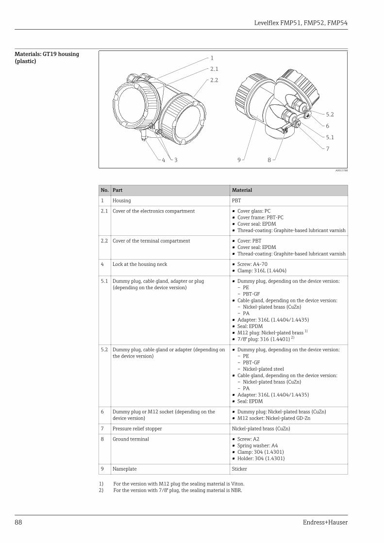
Levelflex FMP51, FMP52, FMP54
88 Endress+Hauser
Materials: GT19 housing(plastic)
2.1
1
2.2
5.2
5.1
6
7
894 3
A0013788
No. Part Material
1 Housing PBT
2.1 Cover of the electronics compartment • Cover glass: PC• Cover frame: PBT-PC• Cover seal: EPDM• Thread-coating: Graphite-based lubricant varnish
2.2 Cover of the terminal compartment • Cover: PBT• Cover seal: EPDM• Thread-coating: Graphite-based lubricant varnish
4 Lock at the housing neck • Screw: A4-70• Clamp: 316L (1.4404)
5.1 Dummy plug, cable gland, adapter or plug(depending on the device version)
• Dummy plug, depending on the device version:– PE– PBT-GF
• Cable gland, depending on the device version:– Nickel-plated brass (CuZn)– PA
• Adapter: 316L (1.4404/1.4435)• Seal: EPDM• M12 plug: Nickel-plated brass 1)
• 7/8" plug: 316 (1.4401) 2)
5.2 Dummy plug, cable gland or adapter (depending onthe device version)
• Dummy plug, depending on the device version:– PE– PBT-GF– Nickel-plated steel
• Cable gland, depending on the device version:– Nickel-plated brass (CuZn)– PA
• Adapter: 316L (1.4404/1.4435)• Seal: EPDM
6 Dummy plug or M12 socket (depending on thedevice version)
• Dummy plug: Nickel-plated brass (CuZn)• M12 socket: Nickel-plated GD-Zn
7 Pressure relief stopper Nickel-plated brass (CuZn)
8 Ground terminal • Screw: A2• Spring washer: A4• Clamp: 304 (1.4301)• Holder: 304 (1.4301)
9 Nameplate Sticker
1) For the version with M12 plug the sealing material is Viton.2) For the version with 7/8" plug, the sealing material is NBR.

Levelflex FMP51, FMP52, FMP54
Endress+Hauser 89
Materials: GT20 housing(die-cast aluminum, powder-coated, seawater-resistant) 2.1
1
2.2
5.2
5.1
6
7
894 3
A0013788
Nr. Part Material
1 Housing, RAL 5012 (blue) • Housing: AlSi10Mg(<0,1% Cu)• Coating: Polyester
2.1 Cover of the electronics compartment; RAL 7035(gray)
• Cover: AlSi10Mg(<0,1% Cu)• Window: Glass• Cover seal: NBR• Seal of the window: NBR• Thread-coating: Graphite-based lubricant varnish
2.2 Cover of the terminal compartment; RAL 7035(gray)
• Cover: AlSi10Mg(<0,1% Cu)• Cover seal: NBR• Thread-coating: Graphite-based lubricant varnish
3 Cover lock • Screw: A4• Clamp: 316L (1.4404)
4 Lock at the housing neck • Screw: A4-70• Clamp: 316L (1.4404)
5.1 Dummy plug, cable gland, adapter or plug(depending on the device version)
• Dummy plug, depending on the device version:– PE– PBT-GF
• Cable gland, depending on the device version:– Nickel-plated brass (CuZn)– PA
• Adapter: 316L (1.4404/1.4435)• Seal: EPDM• M12 plug: Nickel-plated brass 1)
• 7/8" plug: 316 (1.4401) 2)
5.2 Dummy plug, cable gland or adapter (depending onthe device version)
• Dummy plug, depending on the device version:– PE– PBT-GF– Nickel-plated steel
• Cable gland, depending on the device version:– Nickel-plated brass (CuZn)– PA
• Adapter: 316L (1.4404/1.4435)• Seal: EPDM
6 Dummy plug or M12 socket (depending on thedevice version)
• Dummy plug : Nickel-plated brass (CuZn)• M12 socket: Nickel-plated GD-Zn
7 Pressure relief stopper Nickel-plated brass (CuZn)

Levelflex FMP51, FMP52, FMP54
90 Endress+Hauser
Nr. Part Material
8 Ground terminal • Screw: A2• Spring washer: A2• Clamp: 304 (1.4301)• Holder: 304 (1.4301)
9 Nameplate Sticker
1) For the version with M12 plug the sealing material is Viton.2) For the version with 7/8" plug, the sealing material is NBR.

Levelflex FMP51, FMP52, FMP54
Endress+Hauser 91
Materials: Processconnection
Endress+Hauser supplies DIN/EN flanges and threaded process connections made of stainlesssteel according to AISI 316L (DIN/EN material number 1.4404 or 1.4435). With regard to theirtemperature stability properties, the materials 1.4404 and 1.4435 are grouped under 13E0 inEN 1092-1 Tab. 18. The chemical composition of the two materials can be identical.
Levelflex FMP51
Threaded connection FlangeNo. Material
G¾, NPT¾ G1½ NPT1½ DN40...DN200 DN40...DN100
1.1
3
A0013850
1.1
3
A0013852
1.1
3
A0013849
1.1
2
3
A0013854
1.2
2
43
A0013910
1.1 316L (1.4404)
1.2 Alloy C22 (2.4602)
2 ASME: 316/316LEN: 316L (1.4404)JIS: 316L (1.4435)
3 Ceramic Al2O3 99.7 %
4 Cladding: Alloy C22 (2.4602)
Levelflex FMP52
Flange Dairy coupling Tri-ClampNo. Material Approval
EN/ASME/JIS DN50 (DIN 11851) 3" 2" 1½"
1
2
4
A0013865
1
3
4
5
A0013866
1
3
4
A0013867
1
3
4
A0013868
3
4
A0013869
1 316L (1.4404)
2 ASME: 316/316LEN: 316L (1.4404)JIS: 316L (1.4435)
3 316L (1.4404)
4 Coating 2 mm (0.08 in): PTFE (DyneonTFM1600)
USP Cl. VI 1)
5 304L (1.4307)
1) Plastic parts in contact with process have been tested according to USP <88> Class VI-70°C.
Levelflex FMP54
Threaded connection G1½, NPT1½ FlangeNo. Material
HT version XT version HT version XT version
1
27
4
5
6
A0013880
1
4
7 2
5
6
A0013882
1
27
3
4
5
6
A0013881
1
27
3
4
5
6
A0013883
1 316L (1.4404)
2 316L (1.4404)
3 ASME: 316/316LEN: 316L (1.4404)JIS: 316L (1.4435)
4 Alloy C22 (2.4602)
5 316L (1.4404)
6 Nordlock washer: 1.4547
7 Ceramic Al2O3 99.7 %, pure graphite
Levelflex FMP51, FMP52, FMP54
92 Endress+Hauser
Materials: Probe Levelflex FMP51
Rope probe Rod probe Coax probe
No. Material 4 mm(1/6")
4 mm(1/6")with
centeringdisk
8 mm(1/3")
12.7mm (1/2")
AlloyC
ThreadG3/4
ThreadG1-1/2AlloyC
ThreadG1-1/2316L
1.1
2
4
1.1
5
A0013839
1.1
2
1.1
6
7
8
A0013855
1.1
A0013838
1.2
A0013912
1.1
3
9.1
10
A0013856
1.2
9.2
10
A0013911
1.1
9.1
10
A0017244
1.1 316L (1.4404)
1.2 Alloy C22 (2.4602)
2 316 (1.4401)
3 316L (1.4435)
4 Set screw: A4-70
5 Screw for tightening: A2-70
6 Socket cap screw: A4-80
7 Disk: 316L (1.4404)
8 Set screw: A4-70
9.1 Rod: 316L (1.4404)
9.2 Alloy C22 (2.4602)
10 Centering star: PFA
Levelflex FMP51
Rod probeNo. Material 12 mm (1/2")
316L 16 mm (2/3")
divisible
1
12
11
13
A0013860
1
3
3
1
1
13
A0013861
1 316L (1.4404)
3 Connecting bolt: Alloy C22 (2.4602)
Nordlock washer: 1.4547
11 Hexagon head screw: A4-70
Nordlock washer: 1.4547
12 Centering star, PEEK
Center washer, 316L (1.4404)
13 Center washer, PFA
Levelflex FMP51, FMP52, FMP54
Endress+Hauser 93
Levelflex FMP52
Rod probe 16 mm (2/3") coated
Rope probe 4 mm (1/6") coated No. Material
1
2
5
A0013870
1
2
2
2
4
2
3
A0013871
1 316L (1.4404)
2 Coating 2 mm (0.08 in): PFA (Daikin PFA AP230)
3 Rope: 316 (1.4401)
Coating 0.75mm (0.03 in): PFA (Daikin PFA AP230)
4 Core: 316L (1.4435)
5 PFA (Daikin PFA AP230), centering star
Levelflex FMP54
Rope probe Rod probe
Coax probe No. Material 4 mm (1/6")
4 mm (1/6")with centering
disk
16 mm (2/3")with centering
disk
16 mm (2/3")divisible
1.1
2
4
1.1
5
A0013839
1.1
2
1.1
6
7
8
A0013855
1.1
12
11
13
A0013885
9
3
9
13
A0013886
1.1
9
10
A0013864
1.1 316L (1.4404) 1)
2 316 (1.4401)
3 Connecting bolt: Alloy C22 (2.4602)
Nordlock washer: 1.4547
4 Set screw: A4-70
5 Screw for tightening: A2-70
6 Socket cap screw: A4-80
7 Disk: 316L (1.4404)
8 Set screw: A4-70
9 Rod: 316L (1.4404)
10 Centering star: ceramic Al2O3 99.7 %
11 Hexagon head screw: A4-70
Nordlock washer: 1.4547
12 Centering star, PEEK
Center washer, 316L (1.4404)
13 Centering star, PFA
1) For probes with gas phase compensation this is also the material of the reference rod.

Levelflex FMP51, FMP52, FMP54
94 Endress+Hauser
Materials: Mounting bracket
1011
12
12
A0015143
Mounting bracket for version "Sensor remote"
Position Part Material
10 Bracket 316L (1.4404)
11 Bracket 316Ti (1.4571)
Screw/nuts A4-70
Distance sleeves 316Ti (1.4571) or 316L (1.4404)
12 Half-shells 316L (1.4404)

Levelflex FMP51, FMP52, FMP54
Endress+Hauser 95
Materials: Adapter and cablefor remote sensor
1
2
34
A0021722
Adapter and cable for version "Sensor remote"
Position Part Material
1 Cable FRNC
2 Sensor adapter 304 (1.4301)
3 Clamp 316L (1.4404)
Screw A4-70
4 Loop 316 (1.4401)
Crimp sleeve Aluminum
Nameplate 304 (1.4301)

Levelflex FMP51, FMP52, FMP54
96 Endress+Hauser
Materials: Weatherprotection cover
1
2
3
4
5
7
6
A0015473
No Part: Material
1 Protection cover: 316L (1.4404)
2 Molded rubber part (4x): EPDM
3 Clamping screw: 316L (1.4404) + carbon fibre
4 Bracket: 316L (1.4404)
5 • Cheese head screw: A4-70• Nut: A4• Spring washer: A4
6 Ground terminal• Screw: A4• Spring washer: A4• Clamp: 316L (1.4404)• Holder: 316L (1.4404)
7 • Washer: A4• Cheese head screw: A4-70

Levelflex FMP51, FMP52, FMP54
Endress+Hauser 97
Operability
Operating concept Operator-oriented menu structure for user-specific tasks• Commissioning• Operation• Diagnostics• Expert levelOperating languages• English• Deutsch• Français• Español• Italiano• Nederlands• Portuguesa• Polski• русский язык (Russian)• Svenska• Türkçe• 中文 (Chinese)• 日本語 (Japanese)• 한국어 (Korean)• Bahasa Indonesia• tiếng Việt (Vietnamese)• čeština (Czech)
Feature 500 of the product structure determines which of these languages is preset on delivery.
Quick and save commissioning• Interactive wizard with graphical interface for easy commissioning via FieldCare/DeviceCare• Menu guidance with brief explanations of the individual parameter functions• Standardized operation at the device and in the operating toolsIntegrated data storage device (HistoROM)• Enables transfer of configuration when changing electronic modules• Records up to 100 event messages in the device• Records up to 1000 measured values in the device• Saves the signal curve on commissioning which can later be used as a reference.Efficient diagnostics increase measurement reliability• Remedy information is integrated in plain text• Diverse simulation options and line recorder functions
Local operation Order code for "Display; Operation", option C "SD02" Order code for "Display; Operation", option E "SD03"
+
E
–
1
A0015544
1
+
E
–
A0015546
1 Operation with pushbuttons 1 Operation with touch control
Display elements• 4-line display• In the case of order code for "Display; Operation", option E: white background lighting; switches to
red in event of device errors• Format for displaying measured variables and status variables can be individually configured• Permitted ambient temperature for the display: –20 to +70 °C (–4 to +158 °F)
The readability of the display may be impaired at temperatures outside the temperature range.

Levelflex FMP51, FMP52, FMP54
98 Endress+Hauser
Operating elements• In the case of order code "Display; Operation", Option C: local operation with 3 push buttons ( , ,
E )• In the case of order code for "Display; Operation", option E: external operation via touch control; 3
optical keys: , , E
• Operating elements also accessible in various hazardous areasAdditional functionality• Data backup function
The device configuration can be saved in the display module.• Data comparison function
The device configuration saved in the display module can be compared to the current deviceconfiguration.
• Data transfer functionThe transmitter configuration can be transmitted to another device using the display module.
Operation with remotedisplay and operatingmodule FHX50
321
A0013137
34 FHX50 operating options
1 Housing of the remote display and operating module FHX502 Display and operating module SD02, push buttons; cover must be removed3 Display and operating module SD03, optical keys; can be operated through the glass of the cover
Remote operation Via HART protocol
1
2
4 5 7
9
6 83
A0013764
35 Options for remote operation via HART protocol
1 PLC (programmable logic controller)2 Transmitter power supply unit, e.g. RN221N (with communication resistor)3 Connection for Commubox FXA191, FXA195 and Field Communicator 375, 4754 Field Communicator 4755 Computer with operating tool (e.g. FieldCare, AMS Device Manager, SIMATIC PDM)6 Commubox FXA191 (RS232) or FXA195 (USB)7 Field Xpert SFX350/SFX3708 VIATOR Bluetooth modem with connecting cable9 Transmitter

Levelflex FMP51, FMP52, FMP54
Endress+Hauser 99
Via PROFIBUS PA protocol
ENDRESS + HAUSER
T
PROFIBUS DP
PROFIBUS PA
1
23
5
4 4 4
A0015775
1 Segment coupler2 Computer with Profiboard/Proficard and operating tool (e.g. FieldCare)3 PLC (Progrommable Logic Controller)4 Transmitter5 Additional functions (valves etc.)

Levelflex FMP51, FMP52, FMP54
100 Endress+Hauser
Via FOUNDATION Fieldbus
FF-H1
FF-H1
BT
BT
PS
3
4
PS
BT
SB
BT
FF-HSE
IN
LD
ENDRESS + HAUSER
E+–
%
1
1
2
2
A0017188
36 FOUNDATION Fieldbus system architecture with associated components
1 FFblue Bluetooth modem2 Field Xpert SFX350/SFX3703 FieldCare4 NI-FF interface card
IN Industrial network
FF-HSE High Speed Ethernet
FF-H1 FOUNDATION Fieldbus-H1
LD Linking Device FF-HSE/FF-H1
PS Bus Power Supply
SB Safety Barrier
BT Bus Terminator
Levelflex FMP51, FMP52, FMP54
Endress+Hauser 101
Via service interface (CDI)
+
E
–
12
3
A0014019
1 Service interface (CDI) of the measuring device (= Endress+Hauser Common Data Interface)2 Commubox FXA2913 Computer with "FieldCare" operating tool
Levelflex FMP51, FMP52, FMP54
102 Endress+Hauser
Integration in tank gaugingsystem
The Endress+Hauser Tank Side Monitor NRF590 provides integrated communications for sites withmultiple tanks, each with one or more sensors on the tank, such as radar, spot or averagetemperature, capacitive probe for water detection and/or pressure sensors. Multiple protocols out ofthe Tank Side Monitor guarantee connectivity to nearly any of the existing industry standard tankgauging protocols. Optional connectivity of analog 4...20 mA sensors, digital I/O and analog outputsimplify full tank sensor integration. Use of the proven concept of the intrinsically safe HART bus forall on-tank sensors yields extremely low wiring costs, while at the same time providing maximumsafety, reliability and data availability.
NXA820
16...253 VAC
1 2 3
4
6
7
8
5
A0016590
37 The complete measuring system consists of:
1 Tankvision workstation2 Commubox FXA195 (USB) - optional3 Computer with operating tool (ControlCare) - optional4 Level measuring device5 Temperature measuring device6 Tank Side Monitor NRF5907 Pressure measuring device8 Tankvision Tank Scanner NXA820

Levelflex FMP51, FMP52, FMP54
Endress+Hauser 103
System integration viaFieldgate
Vendor Managed Inventory
By using Fieldgates to interrogate tank or silo levels remotely, suppliers of raw materials can providetheir regular customers with information about the current supplies at any time and, for example,account for them in their own production planning. For their part, the Fieldgates monitor theconfigured level limits and, if required, automatically activate the next supply. The spectrum ofoptions here ranges from a simple purchasing requisition via e-mail through to fully automatic orderadministration by coupling XML data into the planning systems on both sides.
Remote maintenance of measuring equipment
Fieldgates not only transfer the current measured values, they also alert the responsible standbypersonnel, if required, via e-mail or SMS. In the event of an alarm or also when performing routinechecks, service technicians can diagnose and configure connected HART devices remotely. All that isrequired for this is the corresponding HART operating tool (e.g. FieldCare, ...) for the connecteddevice. Fieldgate passes on the information transparently, so that all options for the respectiveoperating software are available remotely. Some on-site service operations can be avoided by usingremote diagnosis and remote configuration and all others can at least be better planned andprepared.
-
ENDRESS+HAUSER
RN 221N
ENDRESS+HAUSER
RN 221N
.
20...45 VDC
FX
N 5
20
FX
N 5
20
1 1 2
A0011278
38 The complete measuring system consists of devices and:
1 Fieldgate FXA5202 Multidrop Connector FXN520
The number of instruments which can be connected in mutidrop mode can be calculated by the"FieldNetCalc" program. A description of this program can be found in Technical Information TI400F (Multidrop Conncector FXN520). The program is available form your Endress+Hausersales organisation or in the internet at: www.de.endress.com/Download (text search ="Fieldnetcalc").

Levelflex FMP51, FMP52, FMP54
104 Endress+Hauser
Certificates and approvals
CE mark The measuring system meets the legal requirements of the applicable EC guidelines. These are listedin the corresponding EC Declaration of Conformity together with the standards applied.
Endress+Hauser confirms successful testing of the device by affixing to it the CE mark.
RoHS The measuring system complies with the substance restrictions of the Restriction on HazardousSubstances Directive 2011/65/EU (RoHS 2).
RCM-Tick marking The supplied product or measuring system meets the ACMA (Australian Communications and MediaAuthority) requirements for network integrity, interoperability, performance characteristics as wellas health and safety regulations. Here, especially the regulatory arrangements for electromagneticcompatibility are met. The products are labelled with the RCM- Tick marking on the name plate.
A0029561
Ex approval The devices are certified for use in hazardous areas and the relevant safety instructions are providedin the separate "Safety Instructions" (XA) document. Reference is made to this document on thenameplate.
The separate documentation "Safety Instructions" (XA) containing all the relevant explosionprotection data is available from your Endress+Hauser Sales Center. Correlation ofdocumentations to the device → 126.
Dual seal according toANSI/ISA 12.27.01
The devices have been designed according to ANSI/ISA 12.27.01 as dual seal devices, allowing theuser to waive the use and save the cost of installing external secondary process seals in the conduitas required by the process sealing sections of ANSI/NFPA 70 (NEC) and CSA 22.1 (CEC). Theseinstruments comply with the North-American installation practice and provide a very safe and cost-saving installation for pressurized applications with hazardous fluids.
Further information can be found in the Safety Instructions (XA) of the relevant devices.
Functional Safety Used for level monitoring (MIN, MAX, range) up to SIL 3 (homogeneous redundancy), independentlyassessed by TÜV Rhineland as per IEC 61508. Other information see documentation SD00326F:"Functional Safety Manual".
Overfill prevention WHG
DIBt Z-65.16-501

Levelflex FMP51, FMP52, FMP54
Endress+Hauser 105
Sanitary compatibility The following table shows which device versions meet the requirements of 3A-Sanitary Standard No.74 and are certified by the EHEDG.
FMP52
Feature Option 3A EHEDG
060: Probe CARod 16mm PFA>316L
CBRod 0.63 in PFA>316L
100: Process connection TAKTri-Clamp ISO2852 DN40-51 (2"), PTFE>316L
TLKTri-Clamp ISO2852 DN70-76.1 (3"), PTFE>316L
TNKTri-Clamp ISO2852 DN38 (1-1/2"), PTFE>316L
Suitable fittings and seals must be used to ensure hygiene-compliant design according to thespecifications of 3A and EHEDG.The gap-free connections can be cleaned without residue using the usual cleaning methods (CIPand SIP).Wetted non-metallic parts of the FMP52 conform to FDA 21 CFR 177.1550 and USP Class VI.
AD2000 • For FMP51/FMP54:The wetted material 316L (1.4435/1.4404) corresponds to AD2000 - W2/W10.
• For FMP52/FMP55:The pressure retaining material 316L (1.4435/1.4404) corresponds to AD2000 - W2/W10.
• Declaration of conformity: see product structure, feature 580, option JF.
NACE MR 0175 / ISO 15156 For FMP51, FMP54, FMP55:• The wetted, metallic materials comply with the requirements of NACE MR 0175 / ISO 15156.• Declaration of conformity: see product structure, feature 580, option JB.
NACE MR 0103 For FMP51, FMP54, FMP55:• The wetted, metallic materials comply with the requirements of NACE MR 0103.• The certificate of compliance is based on NACE MR 0175.
The hardness and the intercrystalline corrision have been tested, as well as the heat treatment(solution annealed) has been carried out. The used materials comply therefore with therequirements of NACE MR 0103.
• Declaration of conformity: see product structure, feature 580, option JE.
ASME B31.1 and B31.3 • The dimensions, materials of construction, pressure / temperature ratings and identificationmarkings of the device comply with the requirements of AMSE B31.1 and ASME B31.3
• Declaration of conformity: see product structure, feature 580, option KV.
Pressure EquipmentDirective
Conformity assessment was carried out as per Module A, the proof of statical stability and endurancestrength as per EN 13445 and AD2000.
The FMP54 corresponds to the 97/23/EC Directive (Pressure Equipment Directive). It is apressure accessory with a volume < 0.1 l, corresponding to Category I.
The FMP54 is not suitable for use with unstable gases at nominal pressures above200 bar (2 900 psi).
Steam boiler approval The FMP54 is approved as a limiting device for high water (HW) and low water (LW) for liquids incontainers which are subject to the requirements of EN12952-11 and EN12953-9 (certified by TÜVNord).
Product structure: Feature 590 "Additional Approval", option LX "Steam boiler approval".

Levelflex FMP51, FMP52, FMP54
106 Endress+Hauser
For details refer to Safety Instructions SD00349F and Planning Recommendations SD01071F.
Device with steam boiler approval always have a SIL approval as well.
Marine certificate Device Marine certificate 1)
GL ABS LR BV DNV
FMP51
FMP52
FMP54 - - - - -
1) see oredering feature 590 "Additional approval"
Telecommunications Complies with part 15 of the FCC rules for an unintentional radiator. All probes meet therequirements for a Class A digital device.
In addition, all probes in metallic tanks as well as the coax probe meet the requirements for a Class Bdigital device.
CRN approval Some device versions have a CRN approval. Devices are CRN approved if the folowing two conditionsare met:
• The device has a CSA or FM approval (Product structure: Feature 010 "Approval")• The device has a CRN approved process connection according to the following table.
Feature 100 of the product structure Approval
AAJ NPS 2" Cl. 600 RF, 316/316L flange ASME B16.5
ABJ NPS 3" Cl. 600 RF, 316/316L flange ASME B16.5
AEJ NPS 1-1/2" Cl. 150 RF, 316/316L flange ASME B16.5
AEK NPS 1-1/2" Cl. 150, PTFE>316/316L flange ASME B16.5
AEM NPS 1-1/2" Cl. 150, AlloyC>316/316L flange ASME B16.5
AFJ NPS 2" Cl. 150 RF, 316/316L flange ASME B16.5
AFK NPS 2" Cl. 150, PTFE>316/316L flange ASME B16.5
AFM NPS 2" Cl. 150, AlloyC>316/316L flange ASME B16.5
AGJ NPS 3" Cl. 150 RF, 316/316L flange ASME B16.5
AGK NPS 3" Cl. 150, PTFE>316/316L flange ASME B16.5
AGM NPS 3" Cl. 150, AlloyC>316/316L flange ASME B16.5
AHJ NPS 4" Cl. 150 RF, 316/316L flange ASME B16.5
AHK NPS 4" Cl. 150, PTFE>316/316L flange ASME B16.5
AJJ NPS 6" Cl. 150 RF, 316/316L flange ASME B16.5
AJK NPS 6" Cl. 150, PTFE>316/316L flange ASME B16.5
AKJ NPS 8" Cl. 150 RF, 316/316L flange ASME B16.5
AOJ NPS 4" Cl. 600 RF, 316/316L flange ASME B16.5
AQJ NPS 1-1/2" Cl. 300 RF, 316/316L flange ASME B16.5
AQK NPS 1-1/2" Cl. 300, PTFE>316/316L flange ASME B16.5
AQM NPS 1-1/2" Cl. 300, AlloyC>316/316L flange ASME B16.5
ARJ NPS 2" Cl. 300 RF, 316/316L flange ASME B16.5
ARK NPS 2" Cl. 300, PTFE>316/316L flange ASME B16.5
ARM NPS 2" Cl. 300, AlloyC>316/316L flange ASME B16.5
ASJ NPS 3" Cl. 300 RF, 316/316L flange ASME B16.5
ASK NPS 3" Cl. 300, PTFE>316/316L flange ASME B16.5
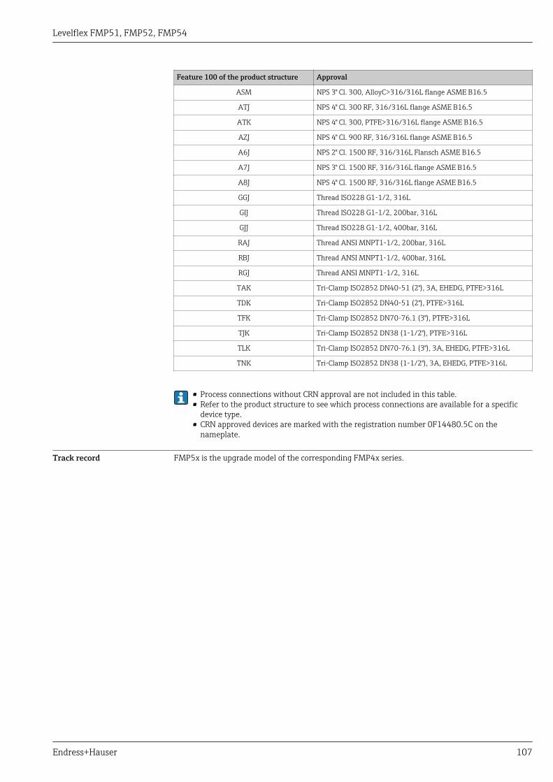
Levelflex FMP51, FMP52, FMP54
Endress+Hauser 107
Feature 100 of the product structure Approval
ASM NPS 3" Cl. 300, AlloyC>316/316L flange ASME B16.5
ATJ NPS 4" Cl. 300 RF, 316/316L flange ASME B16.5
ATK NPS 4" Cl. 300, PTFE>316/316L flange ASME B16.5
AZJ NPS 4" Cl. 900 RF, 316/316L flange ASME B16.5
A6J NPS 2" Cl. 1500 RF, 316/316L Flansch ASME B16.5
A7J NPS 3" Cl. 1500 RF, 316/316L flange ASME B16.5
A8J NPS 4" Cl. 1500 RF, 316/316L flange ASME B16.5
GGJ Thread ISO228 G1-1/2, 316L
GIJ Thread ISO228 G1-1/2, 200bar, 316L
GJJ Thread ISO228 G1-1/2, 400bar, 316L
RAJ Thread ANSI MNPT1-1/2, 200bar, 316L
RBJ Thread ANSI MNPT1-1/2, 400bar, 316L
RGJ Thread ANSI MNPT1-1/2, 316L
TAK Tri-Clamp ISO2852 DN40-51 (2"), 3A, EHEDG, PTFE>316L
TDK Tri-Clamp ISO2852 DN40-51 (2"), PTFE>316L
TFK Tri-Clamp ISO2852 DN70-76.1 (3"), PTFE>316L
TJK Tri-Clamp ISO2852 DN38 (1-1/2"), PTFE>316L
TLK Tri-Clamp ISO2852 DN70-76.1 (3"), 3A, EHEDG, PTFE>316L
TNK Tri-Clamp ISO2852 DN38 (1-1/2"), 3A, EHEDG, PTFE>316L
• Process connections without CRN approval are not included in this table.• Refer to the product structure to see which process connections are available for a specific
device type.• CRN approved devices are marked with the registration number 0F14480.5C on the
nameplate.
Track record FMP5x is the upgrade model of the corresponding FMP4x series.
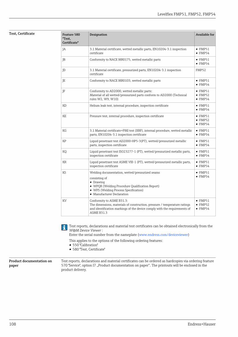
Levelflex FMP51, FMP52, FMP54
108 Endress+Hauser
Test, Certificate Feature 580"Test,Certificate"
Designation Available for
JA 3.1 Material certificate, wetted metallic parts, EN10204-3.1 inspectioncertificate
• FMP51• FMP54
JB Conformity to NACE MR0175, wetted metallic parts • FMP51• FMP54
JD 3.1 Material certificate, pressurized parts, EN10204-3.1 inspectioncertificate
FMP52
JE Conformity to NACE MR0103, wetted metallic parts • FMP51• FMP54
JF Conformity to AD2000, wetted metallic parts:Material of all wetted/pressurized parts conform to AD2000 (Technicalrules W2, W9, W10)
• FMP51• FMP52• FMP54
KD Helium leak test, internal procedure, inspection certificate • FMP51• FMP54
KE Pressure test, internal procedure, inspection certificate • FMP51• FMP52• FMP54
KG 3.1 Material certificate+PMI test (XRF), internal procedure, wetted metallicparts, EN10204-3.1 inspection certificate
• FMP51• FMP54
KP Liquid penetrant test AD2000-HP5-3(PT), wetted/pressurized metallicparts, inspection certificate
• FMP51• FMP54
KQ Liquid penetrant test ISO23277-1 (PT), wetted/pressurized metallic parts,inspection certificate
• FMP51• FMP54
KR Liquid penetrant test ASME VIII-1 (PT), wetted/pressurized metallic parts,inspection certificate
• FMP51• FMP54
KS Welding documentation, wetted/pressurized seams
consisting of• Drawing• WPQR (Welding Procedure Qualification Report)• WPS (Welding Process Specification)• Manufacturer Declaration
• FMP51• FMP54
KV Conformity to ASME B31.3:The dimensions, materials of construction, pressure / temperature ratingsand identification markings of the device comply with the requirements ofASME B31.3
• FMP51• FMP52• FMP54
Test reports, declarations and material test certificates can be obtained electronically from theW@M Device Viewer :Enter the serial number from the nameplate (www.endress.com/deviceviewer)This applies to the options of the following ordering features:• 550 "Calibration"• 580 "Test, Certificate"
Product documentation onpaper
Test reports, declarations and material certificates can be ordered as hardcopies via ordering feature570 "Service", option I7 „Product documentation on paper“. The printouts will be enclosed in theproduct delivery.
Levelflex FMP51, FMP52, FMP54
Endress+Hauser 109
Other standards andguidelines
• EN 60529Degrees of protection by housing (IP code)
• EN 61010-1Protection Measures for Electrical Equipment for Measurement, Control, Regulation andLaboratory Procedures.
• IEC/EN 61326"Emission in accordance with Class A requirements". Electromagnetic compatibility (EMCrequirements)
• NAMUR NE 21Electromagnetic compatibility (EMC) of industrial process and laboratory control equipment.
• NAMUR NE 43Standardization of the signal level for the breakdown information of digital transmitters withanalog output signal.
• NAMUR NE 53Software of field devices and signal-processing devices with digital electronics
• NAMUR NE 107Status classification as per NE107
• NAMUR NE 131Requirements for field devices for standard applications
• IEC61508Functional safety of electrical/electronic/programmable electronic safety-related systems

Levelflex FMP51, FMP52, FMP54
110 Endress+Hauser
Ordering information
Ordering information Detailed ordering information is available from the following sources:• In the Product Configurator on the Endress+Hauser website: www.endress.com -> Click "Corporate"
-> Select your country -> Click "Products" -> Select the product using the filters and search field ->Open product page -> The "Configure" button to the right of the product image opens the ProductConfigurator.
• From your Endress+Hauser Sales Center: www.addresses.endress.comProduct Configurator - the tool for individual product configuration• Up-to-the-minute configuration data• Depending on the device: Direct input of measuring point-specific information such as
measuring range or operating language• Automatic verification of exclusion criteria• Automatic creation of the order code and its breakdown in PDF or Excel output format• Ability to order directly in the Endress+Hauser Online Shop

Levelflex FMP51, FMP52, FMP54
Endress+Hauser 111
3-point linearity protocol The following notes must be taken into account if option F3 ("3 point linearity protocol") hasbeen selected in feature 550 ("Calibration").
Depending on the probe the 3 points of the linearity protocol are defined as follows:
R
AC
BLN
1 1
3 3
2 2
A0021843
A Distance from reference point R to first measuring pointB Measuring rangeC Distance from end of probe to third measuring pointLN Length of probeR Reference point of the measurement1 First measuring point2 Second measuring point (centrally between first and third measuring point)3 Third measuring point
Rod or coax probe 1)
LN ≤ 6 m (20 ft)Divisible rod probeLN > 6 m (20 ft)
Rope probeLN ≤ 6 m (20 ft)
Rope probeLN > 6 m (20 ft)
Position of 1st measuringpoint
• FMP51/FMP52/FMP54 withoput gas phase compensation/FMP55:A = 350 mm (13.8 in)
• FMP54 with gas phase compensation, Lref = 300 mm (11 in):A = 600 mm (23.6 in)
• FMP54 with gas phase compensation, Lref = 550 mm (21 in):A = 850 mm (33.5 in)
A = 350 mm (13.8 in) A = 350 mm (13.8 in)
Position of 2nd measuringpoint
centrally between 1st and3rd measuring point
centrally between 1st and 3rdmeasuring point
centrally between 1st and3rd measuring point
centrally between 1st and3rd measuring point
Position of 3rd measuringpoint
measured from thebottom end of the probe:C = 250 mm (9.84 in)
measured from the top end of theprobe:A+B = 5 750 mm (226 in)
measured from thebottom end of the probe:C = 500 mm (19.7 in)
measured from the topend of the probe:A+B = 5 500 mm (217 in)
Minimum measuringrange
B ≥ 400 mm (15.7 in) B ≥ 400 mm (15.7 in) B ≥ 400 mm (15.7 in) B ≥ 400 mm (15.7 in)
Minimum length of probe LN ≥ 1 000 mm (39.4 in) LN ≥ 1 000 mm (39.4 in) LN ≥ 1 250 mm (49.2 in) LN ≥ 1 250 mm (49.2 in)
1) also valid for divisible rods
The position of the measuring points may vary by ±1 cm (±0.04 in).
• For rod and rope probes the linearity check is performed with the complete device.• For divisible rod probes a reference probe is used instead of the original one.• For coax probes the electronics is mounted to a reference rod probe and the linearity check is
performed to this configuration.• The linearity is checked under reference conditions.
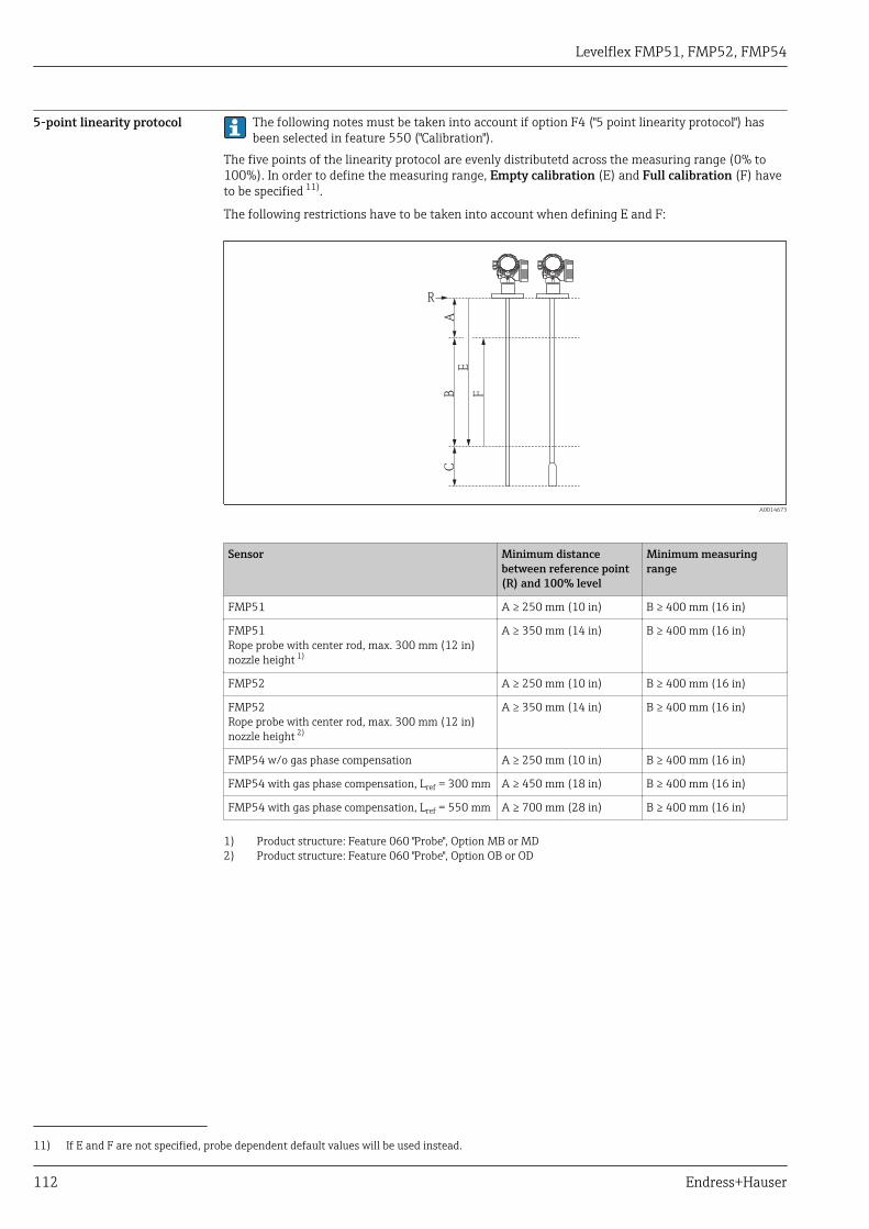
Levelflex FMP51, FMP52, FMP54
112 Endress+Hauser
5-point linearity protocol The following notes must be taken into account if option F4 ("5 point linearity protocol") hasbeen selected in feature 550 ("Calibration").
The five points of the linearity protocol are evenly distributetd across the measuring range (0% to100%). In order to define the measuring range, Empty calibration (E) and Full calibration (F) haveto be specified 11).
The following restrictions have to be taken into account when defining E and F:
R
AC
B F
E
A0014673
Sensor Minimum distancebetween reference point(R) and 100% level
Minimum measuringrange
FMP51 A ≥ 250 mm (10 in) B ≥ 400 mm (16 in)
FMP51Rope probe with center rod, max. 300 mm (12 in)nozzle height 1)
A ≥ 350 mm (14 in) B ≥ 400 mm (16 in)
FMP52 A ≥ 250 mm (10 in) B ≥ 400 mm (16 in)
FMP52Rope probe with center rod, max. 300 mm (12 in)nozzle height 2)
A ≥ 350 mm (14 in) B ≥ 400 mm (16 in)
FMP54 w/o gas phase compensation A ≥ 250 mm (10 in) B ≥ 400 mm (16 in)
FMP54 with gas phase compensation, Lref = 300 mm A ≥ 450 mm (18 in) B ≥ 400 mm (16 in)
FMP54 with gas phase compensation, Lref = 550 mm A ≥ 700 mm (28 in) B ≥ 400 mm (16 in)
1) Product structure: Feature 060 "Probe", Option MB or MD2) Product structure: Feature 060 "Probe", Option OB or OD
11) If E and F are not specified, probe dependent default values will be used instead.

Levelflex FMP51, FMP52, FMP54
Endress+Hauser 113
Type of probe Minimum distance fromend of probe to 0% level
Maximum value for"empty calibration"
Rod (not divisible) C ≥ 100 mm (4 in) E ≤ 3.9 m (12.8 ft)
• Coax• Rod (divisible)
C ≥ 100 mm (4 in) E ≤ 5.9 m (19.4 ft)
Rope C ≥ 1 000 mm (40 in) E ≤ 23 m (75 ft)
• For rod and rope probes the linearity check is performed with the complete device.• For coax probes the electronics is mounted to a reference rod probe and the linearity check is
performed to this configuration.• The linearity is checked under reference conditions.The selected values of Empty calibration and Full calibration are only used to record thelinearity protocol and are reset to their probe specific default values thereafter. If valuesdifferent from the default are required, they must be ordered as a customized parametrization→ 114.

Levelflex FMP51, FMP52, FMP54
114 Endress+Hauser
Customized parametrization If the option IJ "Customized parametrization HART", IK "Customized parametrization PA" or IL"Customized parametrization FF" has been selected in feature 570 "Service", customer specificpresettings can be selected for the following parameters:
Parameter Communication Selection list / range ofvalues
Setup → Distance unit • HART• PA• FF
• in• ft• mm• m
Setup → Empty calibration • HART• PA• FF
0 to 45 m (0 to 147 ft)
Setup → Full calibration • HART• PA• FF
0 to 45 m (0 to 147 ft)
Setup → Adv. Setup → Current output 1/2 → Damping HART 0 to 999.9 s
Setup → Adv. Setup → Current output 1/2 → Failure mode HART • Min• Max• Last valid value
Setup → Adv. Setup → Current output 1/2 → Burst mode HART • Off• On
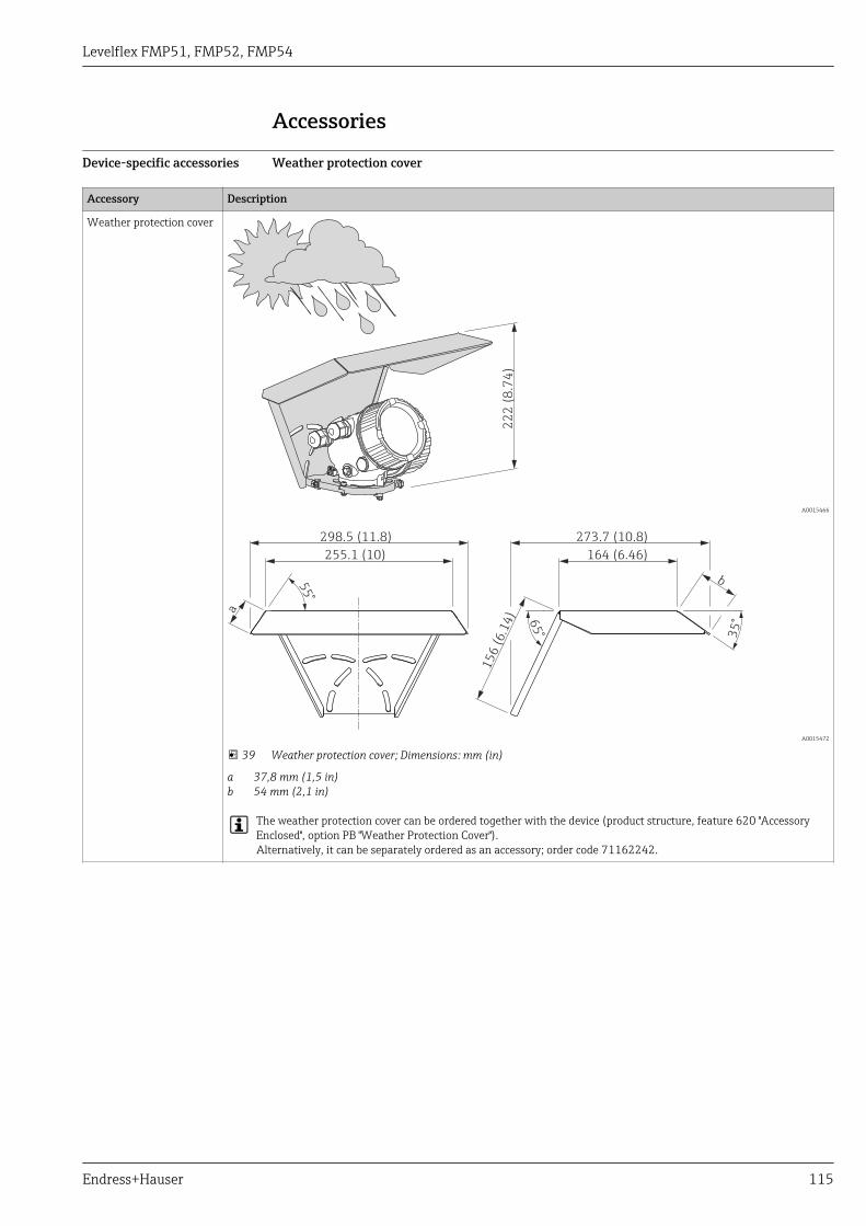
Levelflex FMP51, FMP52, FMP54
Endress+Hauser 115
Accessories
Device-specific accessories Weather protection cover
Accessory Description
Weather protection cover
22
2 (
8.7
4)
A0015466
298.5 (11.8) 273.7 (10.8)
255.1 (10)
15
6(6
.14
)a
164 (6.46)
b
35
°65
°
55
°
A0015472
39 Weather protection cover; Dimensions: mm (in)
a 37,8 mm (1,5 in)b 54 mm (2,1 in)
The weather protection cover can be ordered together with the device (product structure, feature 620 "AccessoryEnclosed", option PB "Weather Protection Cover").Alternatively, it can be separately ordered as an accessory; order code 71162242.
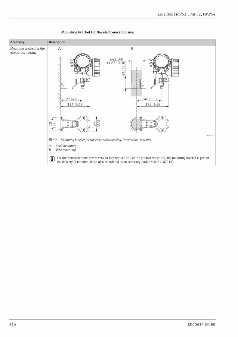
Levelflex FMP51, FMP52, FMP54
116 Endress+Hauser
Mounting bracket for the electronics housing
Accessory Description
Mounting bracket for theelectronics housing
122 (4.8)
52
(2
)
86
(3.4
)
70
(2.8
)
140 (5.5)
158 (6.2) 175 (6.9)
A B
ø42...60(1.65...2.36)
A0014793
40 Mounting bracket for the electronics housing; Dimensions: mm (in)
A Wall mountingB Pipe mounting
For the "Sensor remote" device version (see feature 060 of the product structure), the mounting bracket is part ofthe delivery. If required, it can also be ordered as an accessory (order code 71102216).

Levelflex FMP51, FMP52, FMP54
Endress+Hauser 117
Extension rod / centering HMP40
Accessory Description
Extension rod / centeringHMP40
• can be used for:FMP54
• Admissibletemperatureat lower nozzle edge:– without center
washer:no limitation
– with center washer:-40 to 150 °C(-40 to 302 °F)
• Additional information:SD01002F
1
2 3
A0013597
1 Nozzle height2 Extension rod3 Center washer
010 Approval:
A A: Non-hazardous area
M M: FM DIP Cl.II Div.1 Gr.E-G N.I., zone 21,22
P P: CSA DIP Cl.II Div.1 Gr.G + coal dust N.I.
S S: FM Cl.I, II, III Div.1 Gr.A-G N.I., zone 0,1,2,20,21,22
U U: CSA Cl.I, II, III Div.1 Gr.A-G N.I., zone 0,1,2
1 1: ATEX II 1G
2 2: ATEX II 1D
020 Extension rod; nozzle height:
1 115mm; 150-250mm / 6-10"
2 215mm; 250-350mm / 10-14"
3 315mm; 350-450mm / 14-18"
4 415mm; 450-550mm / 18-22"
9 Special version, TSP-no. to be spec.
030 Center washer:
A Not selected
B DN40 / 1-1/2", inside-d. = 40-45mm, PPS
C DN50 / 2", inside-d. = 50-57mm, PPS
D DN80 / 3", inside-d. = 80-85mm, PPS
E DN80 / 3", inside-d. = 76-78mm, PPS
G DN100 / 4", inside-d. = 100-110mm, PPS
H DN150 / 6", inside-d. = 152-164mm, PPS
J DN200 / 8", inside-d. = 210-215mm, PPS
K DN250 / 10", inside-d. = 253-269mm, PPS
Y Special version, TSP-no. to be spec.
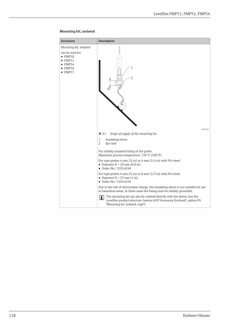
Levelflex FMP51, FMP52, FMP54
118 Endress+Hauser
Mounting kit, isolated
Accessory Description
Mounting kit, isolated
can be used for• FMP50• FMP51• FMP54• FMP56• FMP57
D
1
2
A0013586
41 Scope of supply of the mounting kit:
1 Insulating sleeve2 Eye-bolt
For reliably insulated fixing of the probe.Maximum process temperature: 150 °C (300 °F)
For rope probes 4 mm (¹⁄₆ in) or 6 mm (1/4 in) with PA>steel:• Diameter D = 20 mm (0.8 in)• Order-No.: 52014249
For rope probes 6 mm (¹⁄₄ in) or 8 mm (1/3 in) with PA>steel:• Diameter D = 25 mm (1 in)• Order-No.: 52014250
Due to the risk of electrostatic charge, the insulating sleeve is not suitable for usein hazardous areas. In these cases the fixing must be reliably grounded.
The mounting kit can also be ordered directly with the device (see theLevelflex product structure, feature 620 "Accessory Enclosed", option PG"Mounting kit, isolated, rope").

Levelflex FMP51, FMP52, FMP54
Endress+Hauser 119
Centering star
Accessory Description
Centering star PEEK 48to 95 mm (1.89 to3.74 inch)can be used for
• FMP51• FMP54
10 (0.39)
ø16
(0.6
3)
ø48 (1.89)
ø75 (2.95)
ø95 (3.74)ma
x.
50
(1
.97
)
7 (
0.2
8)
A0014576
The centering star is suitable for probes with a rod diameter of 16 mm (0.6 in) andcan be used in pipes from DN40 (1½") up to DN100 (4"). Markings on the 4-legcentering star ensure a simple tailoring. Hence the centering star can be adapted tothe pipe diameter. See also Operating Instructions BA00377F/00/A2.
• Material of centering star: PEEK (statically dissipative)• Material of retaining rings: PH15-7Mo (UNS S15700)• Admissible process temperature: –60 to +200 °C (–76 to +392 °F)• Order code: 71069064
If the centering star is inserted in a bypass, it must be positioned below thelower bypass outlet. This has to be accounted for when choosing the probelength. Generally, the centering star should not be mounted higher than 50 mm (1.97") from the probe end. It is recommended not to insert the PEEKcentering star in the measuring range of the rod probe.
The PEEK centering star can also be ordered directly with the device (see theLevelflex product structure, feature 610 "Accessory mounted", option OD). Inthis case it is not fastened by the retaining rings. Instead it is fixed to the endof the probe rod by a hexagonal headed bolt (A4-70) and a Nord-Lockwasher (1.4547).
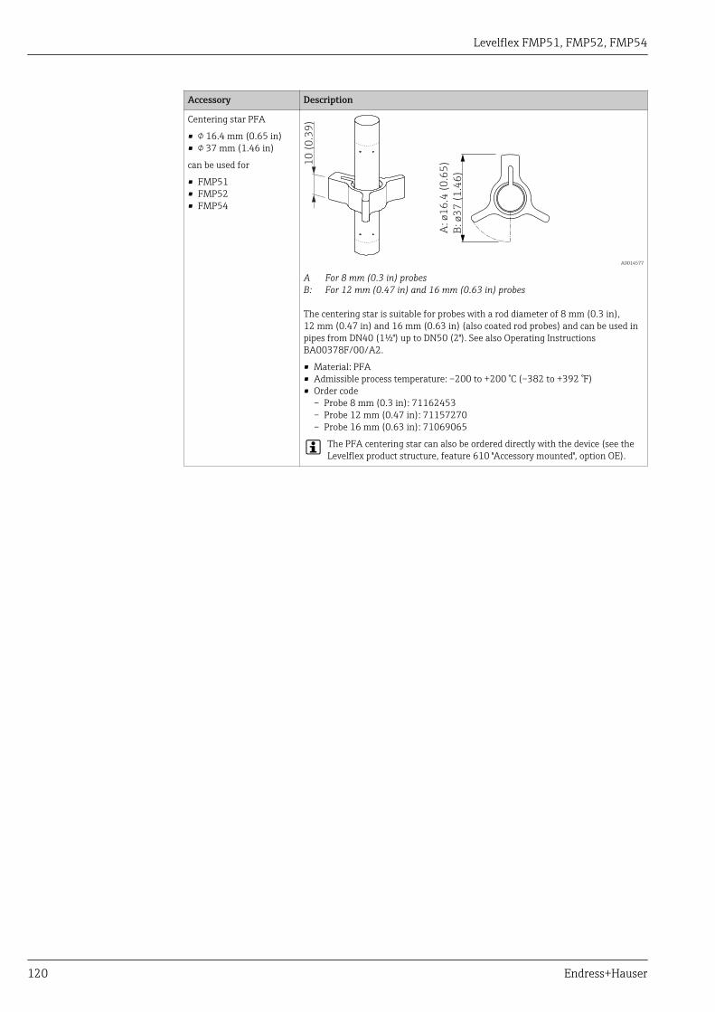
Levelflex FMP51, FMP52, FMP54
120 Endress+Hauser
Accessory Description
Centering star PFA
• 16.4 mm (0.65 in)• 37 mm (1.46 in)
can be used for
• FMP51• FMP52• FMP54
10
(0
.39
)
A:
ø1
6.4
(0
.65
)
B:
ø3
7 (
1.4
6)
A0014577
A For 8 mm (0.3 in) probesB: For 12 mm (0.47 in) and 16 mm (0.63 in) probes
The centering star is suitable for probes with a rod diameter of 8 mm (0.3 in),12 mm (0.47 in) and 16 mm (0.63 in) (also coated rod probes) and can be used inpipes from DN40 (1½") up to DN50 (2"). See also Operating InstructionsBA00378F/00/A2.
• Material: PFA• Admissible process temperature: –200 to +200 °C (–382 to +392 °F)• Order code
– Probe 8 mm (0.3 in): 71162453– Probe 12 mm (0.47 in): 71157270– Probe 16 mm (0.63 in): 71069065
The PFA centering star can also be ordered directly with the device (see theLevelflex product structure, feature 610 "Accessory mounted", option OE).

Levelflex FMP51, FMP52, FMP54
Endress+Hauser 121
Remote display FHX50
Accessory Description
Remote display FHX50
A0019128
• Material:– Plastics PBT– CF3M (similar to 316L/1.4404)– Aluminum (in preparation)
• Ingress protection: IP68 / NEMA 6P and IP66 / NEMA 4x• Suitable for the display modules:
– SD02 (push buttons)– SD03 (touch control)
• Connection cable:– Cable with M12 plug; supplied with the FHX50; up to 30 m (98 ft)– Customer supplied standard cable; up to 60 m (196 ft)
• Ambient temperature: –40 to 80 °C (–40 to 176 °F)
• If the remote display is to be used, the device must be ordered in the version "Prepared for display FHX50"(feature 030, option L or M). For the FHX50, on the other hand, the option A: "Prepared for display FHX50" hasto be selected in feature 050: "Option Measurement Device".
• If a device has not been ordered in the version "Prepared for display FHX50", but is nevertheless to be equippedwith an FHX50, it is essential to select the option B: "Not prepared for display FHX50" in feature 050: "OptionMeasurement Device" of the FHX50. In this case, a retrofit kit, needed to prepare the device for the remotedisplay, is supplied together with the FHX50.
For transmitters with approval, application of the FHX50 may be restricted. A device may only be retrofitted withthe FHX50 if option L or M ("Prepared for FHX50") is quoted under Basic specifications, position 4 "Display,operation" in the associated Safety Instructions (XA).In addition to this, observe the Safety Instructions (XA) of the FHX50.
Do not retrofit transmitters with:• approval for use in areas with combustible dusts (Dust-Ex approval)• type of protection Ex nA
For details refer to the document SD01007F.

Levelflex FMP51, FMP52, FMP54
122 Endress+Hauser
Overvoltage protection
Accessory Description
Overvoltage protection for2-wire-devicesOVP10 (1 channel)OVP20 (2 channel)
A0021734
Technical data• Resistance per channel: 2 * 0.5 Ωmax• Threshold DC voltage: 400 to 700 V• Threshold impulse voltage: < 800 V• Capacitance at 1 MHz: < 1.5 pF• Nominal arrest impulse voltage (8/20 μs): 10 kA• Suited for wire cross-sections: 0.2 to 2.5 mm2 (24 to 14 AWG)
Ordering with deviceThe overvoltage protection module is preferably ordered with the device. See product structure, feature 610"Accessory mounted", option NA "Overvoltage protection". Separate ordering of the module is only necessary if adevice is to retrofitted with the overvoltage protection.
Order code for retrofitting• For 1-channel devices (feature 020, option A)
OVP10: 71128617• For 2-channel devices (feature 020, option B, C, E or G)
OVP20 : 71128619
Hosuing lid for retrofittingIn order to keep the necessary safety distances, the housing lid needs to be replaced if the device is retrofitted withthe overvoltage protection. Depending on the housing type, the order code of the suitable lid is as follows:• GT18 housing: Lid 71185516• GT19 housing: Lid 71185518• GT20 housing: Lid 71185516
Restrictions for retrofittingDepending on the approval of the transmitter the usage of the OVP module may be restricted. A device may only beretrofitted with an OVP module if the option NA (overvoltage protection) is quoted unter Optional Specifications inthe Safety Instructions (XA) pertaining to the device.
For details refer to SD01090F.
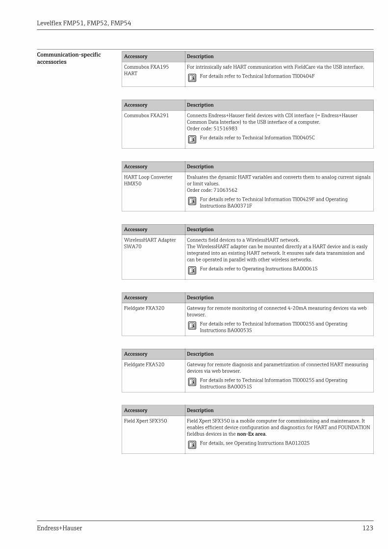
Levelflex FMP51, FMP52, FMP54
Endress+Hauser 123
Communication-specificaccessories
Accessory Description
Commubox FXA195HART
For intrinsically safe HART communication with FieldCare via the USB interface.
For details refer to Technical Information TI00404F
Accessory Description
Commubox FXA291 Connects Endress+Hauser field devices with CDI interface (= Endress+HauserCommon Data Interface) to the USB interface of a computer.Order code: 51516983
For details refer to Technical Information TI00405C
Accessory Description
HART Loop ConverterHMX50
Evaluates the dynamic HART variables and converts them to analog current signalsor limit values.Order code: 71063562
For details refer to Technical Information TI00429F and OperatingInstructions BA00371F
Accessory Description
WirelessHART AdapterSWA70
Connects field devices to a WirelessHART network.The WirelessHART adapter can be mounted directly at a HART device and is easlyintegrated into an existing HART network. It ensures safe data transmission andcan be operated in parallel with other wireless networks.
For details refer to Operating Instructions BA00061S
Accessory Description
Fieldgate FXA320 Gateway for remote monitoring of connected 4-20mA measuring devices via webbrowser.
For details refer to Technical Information TI00025S and OperatingInstructions BA00053S
Accessory Description
Fieldgate FXA520 Gateway for remote diagnosis and parametrization of connected HART measuringdevices via web browser.
For details refer to Technical Information TI00025S and OperatingInstructions BA00051S
Accessory Description
Field Xpert SFX350 Field Xpert SFX350 is a mobile computer for commissioning and maintenance. Itenables efficient device configuration and diagnostics for HART and FOUNDATIONfieldbus devices in the non-Ex area.
For details, see Operating Instructions BA01202S

Levelflex FMP51, FMP52, FMP54
124 Endress+Hauser
Accessory Description
Field Xpert SFX370 Field Xpert SFX370 is a mobile computer for commissioning and maintenance. Itenables efficient device configuration and diagnostics for HART and FOUNDATIONfieldbus devices in the non-Ex area and the Ex area.
For details, see Operating Instructions BA01202S
Service-specific accessories Accessory Description
FieldCare / DeviceCare Endress+Hauser's FDT-based Plant Asset Management tool.Helps to configure and maintain all field devices of your plant. By supplying statusinformation it also supports the diagnosis of the devices.
For details refer to Operating Instructions BA00027S and BA00059S.
System components Accessory Description
Graphic Data ManagerMemograph M
The graphic data manager Memograph M provides information on all the relevantprocess variables. Measured values are recorded correctly, limit values aremonitored and measuring points analyzed. The data are stored in the 256 MBinternal memory and also on an SD card or USB stick.
For details refer to Technical Information TI00133R and OperatingInstructions BA00247R
RN221N Active barrier with power supply for safe separation of 4 to 20 mA current circuits.Provides bi-directional HART transmission.
For details refer to Technical Information TI00073R and OperatingInstructions BA00202R
RNS221 Transmitter supply for 2-wire sensors or transmitters exclusively for non-Ex areas.Provides bi-directional communication using the HART communication sockets.
For details refer to Technical Information TI00081R and OperatingInstructions KA00110R

Levelflex FMP51, FMP52, FMP54
Endress+Hauser 125
DocumentationFor an overview of the scope of the associated Technical Documentation, refer to the following:• The W@M Device Viewer : Enter the serial number from the nameplate
(www.endress.com/deviceviewer)• The Endress+Hauser Operations App: Enter the serial number from the nameplate or scan the
2-D matrix code (QR code) on the nameplate.
Standard documentation Levelflex FMP51, FMP52, FMP54
Correlation of documentations to the device:
Device Power supply,output
Communication Document type Document code
FMP51,FMP52,FMP54
A, B, C, K, L HART Technical Information TI01001F
Operating Instructions BA01001F
Brief Operating Instructions KA01077F
Description of DeviceParameters
GP01000F
G PROFIBUS PA Technical Information TI01001F
Operating Instructions BA01006F
Brief Operating Instructions KA01079F
Description of DeviceParameters
GP01001F
E FOUNDATION Fieldbus Technical Information TI01001F
Operating Instructions BA01052F
Brief Operating Instructions KA01107F
Description of DeviceParameters
GP01015F
Supplementarydocumentation
Device Document type Document code
Fieldgate FXA520 Technical Information TI369F
Tank Side Monitor NRF590 Technical Information TI402F
Operating Instructions BA256F
Description of DeviceParameters
BA257F
Description Document type Document code
Continuous level measurement in liquids and bulk solidsSelection and engineering guide for the process industry
Competence brochure CP00023F
Planning instructions for steam boiler approvalFor Levelflex M FMP45 and Levelflex FMP54
Special documentation SD01071F

Levelflex FMP51, FMP52, FMP54
126 Endress+Hauser
Safety documentation Safety Instructions (XA)
Depending on the approval, the following Safety Instructions (XA) are supplied with the device. Theyare an integral part of the Operating Instructions.
Feature 010 Approval Available for Feature 020: "Power Supply; Output"
A 1) B 2) C 3) E 4)/G 5) K 6)/L 7)
BA ATEX II 1G Ex ia IIC T6 Ga • FMP51• FMP52• FMP54
XA00496F XA01125F XA01126F XA00516F -
BB ATEX II 1/2G Ex ia IIC T6 Ga/Gb • FMP51• FMP52• FMP54
XA00496F XA01125F XA01126F XA00516F -
BC ATEX II 1/2G Ex d[ia] IIC T6 Ga/Gb • FMP51• FMP52• FMP54
XA00499F XA00499F XA00499F XA00519F XA01133F
BD ATEX II 1/3G Ex ic[ia] IIC T6 Ga/Gc • FMP51• FMP52• FMP54
XA00497F XA01127F XA01128F XA00517F -
BE ATEX II 1D Ex t IIIC Da FMP54 XA00501F XA00501F XA00501F XA00521F XA00501F
BF ATEX II 1/2D Ex t IIIC Da/Db FMP54 XA00501F XA00501F XA00501F XA00521F XA00501F
BG ATEX II 3G Ex nA IIC T6 Gc • FMP51• FMP52• FMP54
XA00498F XA01130F XA01131F XA00518F XA01132F
BH ATEX II 3G Ex ic IIC T6 Gc • FMP51• FMP52• FMP54
XA00498F XA01130F XA01131F XA00518F -
BL ATEX II 1/3G Ex nA[ia] IIC T6 Ga/Gc • FMP51• FMP52• FMP54
XA00497F XA01127F XA01128F XA00517F XA01129F
B2 ATEX II 1/2G Ex ia IIC T6 Ga/Gb, 1/2D Ex ia IIIC Da/Db • FMP51• FMP52• FMP54
XA00502F XA00502F XA00502F XA00522F -
B3 ATEX II 1/2G Ex d[ia] IIC T6 Ga/Gb, 1/2 D Ex t IIICDa/Db
• FMP51• FMP52• FMP54
XA00503F XA00503F XA00503F XA00523F XA01136F
B4 ATEX II 1/2G Ex ia IIC T6 Ga/Gb, Ex d[ia] IIC T6 Ga/Gb • FMP51• FMP52• FMP54
XA00500F XA01134F XA01135F XA00520F -
CD CSA C/US DIP Cl.II,III Div.1 Gr.E-G FMP54 XA00529F XA00529F XA00529F XA00570F XA00529F
C2 CSA C/US IS Cl.I,II,III Div.1 Gr.A-G, NI Cl.1 Div.2, Ex ia • FMP51• FMP52• FMP54
XA00530F XA00530F XA00530F XA00571F XA00530F
C3 CSA C/US XP Cl.I,II,III Div.1 Gr.A-G, NI Cl.1 Div.2, Ex d • FMP51• FMP52• FMP54
XA00529F XA00529F XA00529F XA00570F XA00529F
FB FM IS Cl.I,II,III Div.1 Gr.A-G, AEx ia, NI Cl.1 Div.2 • FMP51• FMP52• FMP54
XA00531F XA00531F XA00531F XA00573F XA00531F
FD FM XP Cl.I,II,III Div.1 Gr.A-G, AEx d, NI Cl.1 Div.2 • FMP51• FMP52• FMP54
XA00532F XA00532F XA00532F XA00572F XA00532F
FE FM DIP Cl.II,III Div.1 Gr.E-G FMP54 XA00532F XA00532F XA00532F XA00572F XA00532F
GA EAC Ex ia IIC T6 Ga • FMP51• FMP52• FMP54
XA01380F XA01380F XA01380F XA01381F XA01380F

Levelflex FMP51, FMP52, FMP54
Endress+Hauser 127
Feature 010 Approval Available for Feature 020: "Power Supply; Output"
A 1) B 2) C 3) E 4)/G 5) K 6)/L 7)
GB EAC Ex ia IIC T6 Ga/Gb • FMP51• FMP52• FMP54
XA01380F XA01380F XA01380F XA01381F XA01380F
GC EAC Ex d[ia] IIC T6 Ga/Gb • FMP51• FMP52• FMP54
XA01382F XA01382F XA01382F XA01383F XA01382F
IA IEC Ex ia IIC T6 Ga • FMP51• FMP52• FMP54
XA00496F XA01125F XA01126F XA00516F -
IB IEC Ex ia IIC T6 Ga/Gb • FMP51• FMP52• FMP54
XA00496F XA01125F XA01126F XA00516F -
IC IEC Ex d[ia] IIC T6 Ga/Gb • FMP51• FMP52• FMP54
XA00499F XA00499F XA00499F XA00519F XA01133F
ID IEC Ex ic[ia] IIC T6 Ga/Gc • FMP51• FMP52• FMP54
XA00497F XA01127F XA01128F XA00517F -
IE IEC Ex t IIIC Da FMP54 XA00501F XA00501F XA00501F XA00521F XA00501F
IF IEC Ex t IIIC Da/Db FMP54 XA00501F XA00501F XA00501F XA00521F XA00501F
IG IEC Ex nA IIC T6 Gc • FMP51• FMP52• FMP54
XA00498F XA01130F XA01131F XA00518F XA01132F
IH IEC Ex ic IIC T6 Gc • FMP51• FMP52• FMP54
XA00498F XA01130F XA01131F XA00518F -
IL IEC Ex nA[ia] IIC T6 Ga/Gc • FMP51• FMP52• FMP54
XA00497F XA01127F XA01128F XA00517F XA01129F
I2 IEC Ex ia IIC T6 Ga/Gb, Ex ia IIIC Da/Db • FMP51• FMP52• FMP54
XA00502F XA00502F XA00502F XA00522F -
I3 IEC Ex d [ia] IIC T6 Ga/Gb, Ex t IIIC Da/Db • FMP51• FMP52• FMP54
XA00503F XA00503F XA00503F XA00523F XA01136F
I4 IEC Ex II 1/2G Ex ia IIC T6 Ga/Gb, Ex d[ia] IIC T6 Ga/Gb • FMP51• FMP52• FMP54
XA00500F XA01134F XA01135F XA00520F -
KA KC Ex ia IIC T6 Ga • FMP51• FMP52• FMP54
XA01169F - XA01169F - -
KB KC Ex ia IIC T6 Ga/Gb • FMP51• FMP52• FMP54
XA01169F - XA01169F - -
KC KC Ex d[ia] IIC T6 • FMP51• FMP52• FMP54
- - XA01170F - -
MA INMETRO Ex ia IIC T6 Ga • FMP51• FMP52• FMP54
XA01038F XA01038F XA01038F - XA01038F
MC INMETRO Ex d[ia] IIC T6 Ga/Gb • FMP51• FMP52• FMP54
XA01041F XA01041F XA01041F - XA01041F
ME INMETRO Ex t IIIC Da FMP54 XA01043F XA01043F XA01043F - XA01043F

Levelflex FMP51, FMP52, FMP54
128 Endress+Hauser
Feature 010 Approval Available for Feature 020: "Power Supply; Output"
A 1) B 2) C 3) E 4)/G 5) K 6)/L 7)
MH INMETRO Ex ic IIC T6 Gc • FMP51• FMP52• FMP54
XA01040F XA01040F XA01040F - XA01040F
NA NEPSI Ex ia IIC T6 Ga • FMP51• FMP52• FMP54
XA00634F XA00634F XA00634F XA00640F XA00634F
NB NEPSI Ex ia IIC T6 Ga/Gb • FMP51• FMP52• FMP54
XA00634F XA00634F XA00634F XA00640F XA00634F
NC NEPSI Ex d[ia] IIC T6 Ga/Gb • FMP51• FMP52• FMP54
XA00636F XA00636F XA00636F XA00642F XA00636F
NF NEPSI DIP A20/21 T85…90oC IP66 FMP54 XA00637F XA00637F XA00637F XA00643F XA00637F
NG NEPSI Ex nA II T6 Gc • FMP51• FMP52• FMP54
XA00635F XA00635F XA00635F XA00641F XA00635F
NH NEPSI Ex ic IIC T6 Gc • FMP51• FMP52• FMP54
XA00635F XA00635F XA00635F XA00641F XA00635F
N2 NEPSI Ex ia IIC T6 Ga/Gb, Ex iaD 20/21 T85…90°C • FMP51• FMP52• FMP54
XA00638F XA00638F XA00638F XA00644F XA00638F
N3 NEPSI Ex d[ia] IIC T6 Ga/Gb, DIP A20/21 T85…90°CIP66
• FMP51• FMP52• FMP54
XA00639F XA00639F XA00639F XA00645F XA00639F
8A FM/CSA IS+XP Cl.I,II,III Div.1 Gr.A-G • FMP51• FMP52• FMP54
XA00531FXA00532F
XA00531FXA00532F
XA00531FXA00532F
XA00572FXA00573F
XA00531FXA00532F
1) A: 2-wire; 4-20mA HART2) B: 2-wire; 4-20mA HART, switch output3) C: 2-wire; 4-20mA HART, 4-20mA4) E: 2-wire; FOUNDATION Fieldbus, switch output5) G: 2-wire; PROFIBUS PA, switch output6) K: 4-wire 90-253VAC; 4-20mA HART7) L: 4-wire 10,4-48VDC; 4-20mA HART
For certified devices the relevant Safety Instructions (XA) are indicated on the nameplate.
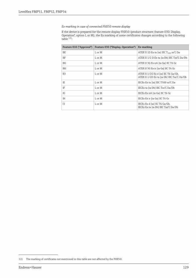
Levelflex FMP51, FMP52, FMP54
Endress+Hauser 129
Ex-marking in case of connected FHX50 remote display
If the device is prepared for the remote display FHX50 (product structure: feature 030: Display,Operation", option L or M), the Ex marking of some certificates changes according to the followingtable 12):
Feature 010 ("Approval") Feature 030 ("Display, Operation") Ex-marking
BE L or M ATEX II 1D Ex ta [ia] IIIC T500 xx°C Da
BF L or M ATEX II 1/2 D Ex ta [ia Db] IIIC Txx°C Da/Db
BG L or M ATEX II 3G Ex nA [ia Ga] IIC T6 Gc
BH L or M ATEX II 3G Ex ic [ia Ga] IIC T6 Gc
B3 L or M ATEX II 1/2G Ex d [ia] IIC T6 Ga/Gb,ATEX II 1/2D Ex ta [ia Db] IIIC Txx°C Da/Db
IE L or M IECEx Ex ta [ia] IIIC T500 xx°C Da
IF L or M IECEx ta [ia Db] IIIC Txx°C Da/Db
IG L or M IECEx Ex nA [ia Ga] IIC T6 Gc
IH L or M IECEx Ex ic [ia Ga] IIC T6 Gc
I3 L or M IECEx Ex d [ia] IIC T6 Ga/Gb,IECEx Ex ta [ia Db] IIIC Txx°C Da/Db
12) The marking of certificates not mentioned in this table are not affected by the FHX50.
Levelflex FMP51, FMP52, FMP54
130 Endress+Hauser
Registered trademarksHART®
Registered trademark of the FieldComm Group, Austin, USA
PROFIBUS®
Registered trademark of the PROFIBUS User Organization, Karlsruhe, Germany
FOUNDATIONTM FieldbusRegistered trademark of the FieldComm Group, Austin, Texas, USA
KALREZ®, VITON®
Registered trademark of DuPont Performance Elastomers L.L.C., Wilmington, USA
TEFLON®
Registered trademark of E.I. DuPont de Nemours & Co., Wilmington, USA
TRI CLAMP®
Registered trademark of Alfa Laval Inc., Kenosha, USA
NORD-LOCK®
Registered trademark of the Nord-Lock International AB
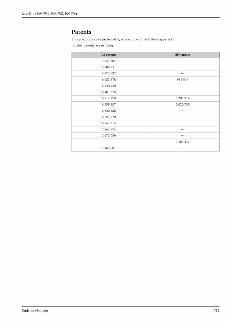
Levelflex FMP51, FMP52, FMP54
Endress+Hauser 131
PatentsThis product may be protected by at least one of the following patents.
Further patents are pending.
US Patents EP Patents
5.827.985 ---
5.884.231 ---
5.973.637 ---
6.087.978 955 527
6.140.940 ---
6.481.276 ---
6.512.358 1 301 914
6.559.657 1 020 735
6.640.628 ---
6.691.570 ---
6.847.214 ---
7.441.454 ---
7.477.059 ---
--- 1 389 337
7.965.087 ---

www.addresses.endress.com
*71320798*71320798