Embed Size (px)
Citation preview

TECHNICAL MANUAL888-2406-002
Platinum Z2CD™FM Transmitter Manual
Platinum Z2 CD™FM Transmitter Manual
T.M. No. 888-2406-002
© Copyright Harris Corporation 2000, 2001, 2005, 2009, 2010All rights reserved
Printed: Jan 29 2010Rev.E


l
t
.
Technical Assistance
HARRIS technical and troubleshooting assistance is available from HARRIS Field Service during normal business hours (8:00 AM - 5:00 PM Central Time). Emergency service is available 24 hours a day by telephone only. Telephone 217/222-8200 to contact the Field Service Department. HARRIS Service may also be contacted via FAX at 217/221-7086.E-mail non-urgent support questions to [email protected]. Other on-line assistance, including technical manuals, white papers, software downloads, and service bulletins is available for no charge at https://premier.harris.com/broadcast/ (log-in required). Address written correspondence to Field Service Department, HARRIS Broadcast Communications Division, P.O. Box 4290, Quincy, Illinois 62305-4290, USA. For global contact information, please visit: http://www.broadcast.harris.com/contact.
Replaceable Parts Service
Replacement parts are available from HARRIS Service Parts Department from 7:00 AM to 11:00 PM Central Time, seven days a week. Telephone 217/222-8200 or email [email protected] to contact the Service Parts Department. Emergency replacement parts are available by telephone only, 24 hours a day, seven days a week by calling 217/222-8200.
Unpacking
Carefully unpack the equipment and preform a visual inspection to determine if any apparent damage was incurred during shipment. Retain the shipping materials until it has been verified that all equipment has been received undamaged. Locate and retain all PACKING CHECK LISTs. Use the PACKING CHECK LIST to help locate and identify any components or assemblies which are removed for shipping and must be reinstalled. Also remove any shipping supports, straps, and packing materials prior to initial turn on.
Returns And Exchanges
No equipment can be returned unless written approval and a Return Authorization is received from HARRIS Broadcast Communications Division. Special shipping instructions and coding will be provided to assure proper handling. Complete details regarding circumstances and reasons for return are to be included in the request for return. Custom equipment or special order equipment is not returnable. In those instances where return or exchange of equipment is at the request of the customer, or convenience of the customer, a restocking fee will be charged. All returns will be sent freight prepaid and properly insured by the customer. When communicating with
Technical Assistance
Technical and troubleshooting assistance for HARRIS Transmission products is available from HARRIS Field Service (factory location: Quincy, Illinois, USA) during normal businesshours (8:00 AM - 5:00 PM Central Time). Telephone +1-217-222-8200 to contact the Field Service Department; FAX +1-217-221-7086; or E-mail questions to [email protected] service is available 24 hours a day, seven days a week, by telephone only. On-line assistance, including technical manuals, white papers, software downloads, and service bulletins, is available at http://support.broadcast.harris.com/eservice_enu. Address written correspondence to Field Service Department, HARRIS Broadcast Communications Division, P.O. Box 4290, Quincy, Illinois 62305-4290, USA. For other global service contact information, please visit: http://www.broadcast.harris.com/contact.NOTE: For all service and parts correspondence, you will need to provide the Sales Order number, as well as the Serial Number for the transmitter or part in question. For future reference, record those numbers here: ___________________/____________________Please provide these numbers for any written request, or have these numbers ready in the event you choose to call regarding any Service, or Parts requests. For warranty claims it wilbe required, and for out of warranty products, this will help us to best identify what specific hardware was shipped.
Replaceable Parts Service
Replacement parts are available from HARRIS Service Parts Department from 7:00 AM to 11:00 PM Central Time, seven days a week. Telephone +1-217-222-8200 or email [email protected] to contact the Service Parts Department. Emergency replacement parts are available by telephone only, 24 hours a day, seven daysa week by calling +1-217-222-8200.
Unpacking
Carefully unpack the equipment and preform a visual inspection to determine if any apparendamage was incurred during shipment. Retain the shipping materials until it has been verifiedthat all equipment has been received undamaged. Locate and retain all PACKING CHECK LISTs. Use the PACKING CHECK LIST to help locate and identify any components or assemblies which are removed for shipping and must be reinstalled. Also remove any shipping supports, straps, and packing materials prior to initial turn on.
Returns And Exchanges
No equipment can be returned unless written approval and a Return Authorization is receivedfrom HARRIS Broadcast Communications Division. Special shipping instructions and coding will be provided to assure proper handling. Complete details regarding circumstancesand reasons for return are to be included in the request for return. Custom equipment or special order equipment is not returnable. In those instances where return or exchange of equipment is at the request of the customer, or convenience of the customer, a restocking feewill be charged. All returns will be sent freight prepaid and properly insured by the customerWhen communicating with HARRIS Broadcast Communications Division, specify the HARRIS Order Number or Invoice Number.
2/1/2010 888-2406-002 iiiWARNING: Disconnect primary power prior to servicing.

iv 888-2406-002 2/1/2010WARNING: Disconnect primary power prior to servicing.

Manual Revision History
Platinum Z2 CD™ Transmitter Technical Manual
REV. DATE ECN Pages Affected
B 12-17-01 47926 Title page, added MRH1/MRH2, sections 2 and 4
C 06-09-03 TBD Title page, MRH1/MRH2 and page 2-30
C1 11-29-06 FS 2-5
D 08-10-09 44801 Revised Title Page up to Table of Contents
E 01-29-10 58638 Title Page, MRH-1, 2-25, 2-32
2/1/2010 888-2406-002 MRH-1WARNING: Disconnect primary power prior to servicing.

MRH-2 888-2406-002 2/1/2010WARNING: Disconnect primary power prior to servicing.

abinet0 001
Guide to Using Harris Parts List InformationThe Harris Replaceable Parts List Index portrays a tree structure with the major items being leftmost in the index. The example below shows the Transmitter as the highest item in the tree structure. If you were to look at the bill of materials table for the Transmitter you would find the Control Cabinet, the PA Cabinet, and the Output Cabinet. In the Replaceable Parts List Index the Control Cabinet, PA Cabinet, and Output Cabinet show up one indentation level below the Transmitter and implies that they are used in the Transmitter. The Controller Board is indented one level below the Control Cabinet so it will show up in the bill of material for the Control Cabinet. The tree structure of this same index is shown to the right of the table and shows indentation level versus tree structure level.
Example of Replaceable Parts List Index and equivalent tree structure:
Replaceable Parts List Index Part Number Page
Table 7-1. Transmitter 994 9283 001 7-2Table 7-2. Control Cabinet 992 9244 002 7-3Table 7-3. Controller Board 992 8344 002 7-6Table 7-4. PA Cabinet 992 9400 002 7-7Table 7-5. PA Amplifier 994 7894 002 7-9Table 7-6. PA Amplifier Board 992 7904 002 7-10Table 7-7. Output Cabinet 992 9450 001 7-12
The part number of the item is shown to the right of the description as is the page in the manual where the bill for that part number starts. Inside the actual tables, four main headings are used:
• Table #-#. ITEM NAME - HARRIS PART NUMBER - this line gives the information that corresponds to the Replaceable Parts List Index entry;
• HARRIS P/N column gives the ten DIGIT Harris part number (usually in ascending order);
• DESCRIPTION column gives a 25 character or less description of the part number;
• REF. SYMBOLS/EXPLANATIONS column 1) gives the Ref Des for the item (i.e., C001, R102, etc.) that corresponds to the number found in the schematics (C001 in a bill of material is equivalent to C1 on the schematic) or 2) gives added information or further explanation (i.e., “Used for 208V operation only,” or “Used for HT 10LS only,” etc.).
NOTE: Inside the individual tables some standard conventions are used:
• A # symbol in front of a component such as #C001 under the REF. SYMBOLS/EXPLANATIONS col-umn means that this item is used on or with C001 and is not the actual part number for C001.
• In the ten digit part numbers, if the last three numbers are 000, the item is a part that Harris has pur-chased and has not manufactured or modified. If the last three numbers are other than 000, the item is either manufactured by Harris or is purchased from a vendor and modified for use in the Harris product.
• The first three digits of the ten DIGIT part number tell which family the part number belongs to - for example, all electrolytic (can) capacitors will be in the same family (524 xxxx 000). If an electrolytic (can) capacitor is found to have a 9xx xxxx xxx part number (a number outside of the normal family of numbers), it has probably been modified in some manner at the Harris factory and will therefore show up farther down into the individual parts list (because each table is normally sorted in ascending order). Most Harris made or modified assemblies will have 9xx xxxx xxx numbers associated with them.
The term “SEE HIGHER LEVEL BILL” in the description column implies that the reference designated part number will show up in a bill that is higher in the tree structure. This is often the case for components that may be frequency determinant or voltage determinant and are called out in a higher level bill structure that is more customer dependent than the bill at a lower level.
Transmitter994 9283 001
Control Cabinet 992 9244 002
Controller Board 992 8344 002
PA Cabinet992 9400 002
PA Amplifier992 7894 002
PA Amplifier Board 992 7904 002
Output C 992 945
2/1/2010 888-2406-002 viiWARNING: Disconnect primary power prior to servicing.

viii 888-2406-002 2/1/2010WARNING: Disconnect primary power prior to servicing.

2/1/2010 888-2406-002 MRH-1WARNING: Disconnect primary power prior to servicing.


! WARNING:THE CURRENTS AND VOLTAGES IN THIS EQUIPMENT ARE DANGEROUS. PERSONNEL MUST AT ALL TIMES OBSERVE SAFETY WARNINGS, INSTRUC-TIONS AND REGULATIONS.
This manual is intended as a general guide for trained and qualified personnel who are aware of the dangers inherent in handling potentially hazardous electrical/electronic circuits. It is not intended to contain a complete statement of all safety precautions which should be observed by personnel in using this or other electronic equipment.
The installation, operation, maintenance and service of this equipment involves risks both to personnel and equipment, and must be performed only by qualified personnel exercising due care. HARRIS CORPORATION shall not be responsible for injury or damage resulting from improper procedures or from the use of improperly trained or inexperienced personnel performing such tasks. During installation and operation of this equipment, local building codes and fire protection standards must be observed.
The following National Fire Protection Association (NFPA) standards are recommended as reference:
- Automatic Fire Detectors, No. 72E- Installation, Maintenance, and Use of Portable Fire Extinguishers, No. 10- Halogenated Fire Extinguishing Agent Systems, No. 12A
! WARNING:ALWAYS DISCONNECT POWER BEFORE OPENING COVERS, DOORS, ENCLO-SURES, GATES, PANELS OR SHIELDS. ALWAYS USE GROUNDING STICKS AND SHORT OUT HIGH VOLTAGE POINTS BEFORE SERVICING. NEVER MAKE INTERNAL ADJUSTMENTS, PERFORM MAINTENANCE OR SERVICE WHEN ALONE OR WHEN FATIGUED.
Do not remove, short-circuit or tamper with interlock switches on access covers, doors, enclosures, gates, panels or shields. Keep away from live circuits, know your equipment and don’t take chances.
! WARNING:IN CASE OF EMERGENCY ENSURE THAT POWER HAS BEEN DISCONNECTED.
! WARNING:IF OIL FILLED OR ELECTROLYTIC CAPACITORS ARE UTILIZED IN YOUR EQUIPMENT, AND IF A LEAK OR BULGE IS APPARENT ON THE CAPACITOR CASE WHEN THE UNIT IS OPENED FOR SERVICE OR MAINTENANCE, ALLOW THE UNIT TO COOL DOWN BEFORE ATTEMPTING TO REMOVE THE DEFEC-TIVE CAPACITOR. DO NOT ATTEMPT TO SERVICE A DEFECTIVE CAPACITOR WHILE IT IS HOT DUE TO THE POSSIBILITY OF A CASE RUPTURE AND SUBSE-QUENT INJURY.
2/1/2010 888-2406-002 xiWARNING: Disconnect primary power prior to servicing.

FIRST-AID
xii 888-2406-002 2/1/2010WARNING: Disconnect primary power prior to servicing.
Personnel engaged in the installation, operation, maintenance or servicing of this equipment are urged to become familiar with first-aid theory and practices. The following information is not intended to be complete first-aid procedures, it is a brief and is only to be used as a reference. It is the duty of all personnel using the equipment to be prepared to give adequate Emergency First Aid and there by prevent avoidable loss of life.
Treatment of Electrical Burns
1. Extensive burned and broken skin
a. Cover area with clean sheet or cloth. (Cleanest available cloth article.)
b. Do not break blisters, remove tissue, remove adhered particles of clothing, or apply any salve or ointment.
c. Treat victim for shock as required.
d. Arrange transportation to a hospital as quickly as possible.
e. If arms or legs are affected keep them elevated.
NOTE:If medical help will not be available within an hour and the victim is conscious and not vomiting, give him a weak solution of salt and soda: 1 level teaspoonful of salt and 1/2 level teaspoonful of baking soda to each quart of water (neither hot or cold). Allow victim to sip slowly about 4 ounces (a half of glass) over a period of 15 minutes. Discontinue fluid if vomiting occurs. (Do not give alcohol.)
2. Less severe burns - (1st & 2nd degree)
a. Apply cool (not ice cold) compresses using the cleanest available cloth article.
b. Do not break blisters, remove tissue, remove adhered particles of clothing, or apply salve or ointment.
c. Apply clean dry dressing if necessary.
d. Treat victim for shock as required.
e. Arrange transportation to a hospital as quickly as possible.
f. If arms or legs are affected keep them elevated.
REFERENCE:ILLINOIS HEART ASSOCIATIONAMERICAN RED CROSS STANDARD FIRST AID AND PERSONAL SAFETY MANUAL (SECOND EDITION)
2/1/2010 888-2406-002 xiiiWARNING: Disconnect primary power prior to servicing.

xiv 888-2406-002 2/1/2010WARNING: Disconnect primary power prior to servicing.

Table of Contents
1 Introduction/SpecificationsIntroduction . . . . . . . . . . . . . . . . . . . . . . . . . . . . . . . . . 1-1Features/Benefits . . . . . . . . . . . . . . . . . . . . . . . . . . . . . 1-2General Description. . . . . . . . . . . . . . . . . . . . . . . . . . . 1-2
Harris DIGIT Digital FM Exciter . . . . . . . . . . . . . . . 1-3Harris SuperCiter Analog Exciter . . . . . . . . . . . . . . . 1-3Redundant Exciters . . . . . . . . . . . . . . . . . . . . . . . . . . 1-3PA/IPA Modules . . . . . . . . . . . . . . . . . . . . . . . . . . . . 1-3RF Combining. . . . . . . . . . . . . . . . . . . . . . . . . . . . . . 1-4Control System . . . . . . . . . . . . . . . . . . . . . . . . . . . . . 1-4Directional RF Sample Port . . . . . . . . . . . . . . . . . . . 1-5Power Supplies . . . . . . . . . . . . . . . . . . . . . . . . . . . . . 1-5Air System . . . . . . . . . . . . . . . . . . . . . . . . . . . . . . . . 1-5
Performance Specifications . . . . . . . . . . . . . . . . . . . . . 1-5
2 Installation & Initial Turn-OnIntroduction . . . . . . . . . . . . . . . . . . . . . . . . . . . . . . . . . 2-1Unpacking . . . . . . . . . . . . . . . . . . . . . . . . . . . . . . . . . . 2-1Returns and Exchanges . . . . . . . . . . . . . . . . . . . . . . . . 2-1Air Cooling Requirements. . . . . . . . . . . . . . . . . . . . . . 2-2Z2 Transmitter Installation . . . . . . . . . . . . . . . . . . . . . 2-2
Transmitter Placement . . . . . . . . . . . . . . . . . . . . . . . 2-3Removal of Pallet Bolts . . . . . . . . . . . . . . . . . . . . . 2-3
Visual Inspection. . . . . . . . . . . . . . . . . . . . . . . . . . . . 2-3Exciter Installation . . . . . . . . . . . . . . . . . . . . . . . . . . 2-43-Phase Power Supply Installation . . . . . . . . . . . . . . 2-5
Power Transformer Tapping. . . . . . . . . . . . . . . . . . 2-5Power Supply Connections . . . . . . . . . . . . . . . . . . 2-5Dual Power Supply Option. . . . . . . . . . . . . . . . . . . 2-8
Single Phase Power Supply Installation . . . . . . . . . . 2-9Power Transformer Tapping. . . . . . . . . . . . . . . . . . 2-9Power Supply Connections . . . . . . . . . . . . . . . . . . 2-9Dual Power Supply Option. . . . . . . . . . . . . . . . . . 2-12
Transmitter AC Connections. . . . . . . . . . . . . . . . . . 2-13Information concerning some 360 to 416 volt systems2-13
Three Phase AC Connection . . . . . . . . . . . . . . . . 2-14Single Phase AC Connection . . . . . . . . . . . . . . . . 2-15Grounding. . . . . . . . . . . . . . . . . . . . . . . . . . . . . . . 2-15Low Voltage Power Supply and Blower . . . . . . . 2-16Exciter AC Voltage Selection. . . . . . . . . . . . . . . . 2-16
RF Output Connection . . . . . . . . . . . . . . . . . . . . . . 2-16Audio Input Connections . . . . . . . . . . . . . . . . . . . . 2-16External and Failsafe Interlock Connections . . . . . 2-17
External Interlock Connection . . . . . . . . . . . . . . . 2-17
Failsafe Interlock Connection . . . . . . . . . . . . . . . 2-17Initial Turn-on . . . . . . . . . . . . . . . . . . . . . . . . . . . . . . 2-18Remote Control Connections . . . . . . . . . . . . . . . . . . 2-23
Remote/Extended Control and Status Connections 2-24Typical remote/extended control and status connec-tions . . . . . . . . . . . . . . . . . . . . . . . . . . . . . . . . . . 2-25
Extended Metering. . . . . . . . . . . . . . . . . . . . . . . . 2-26UPS IN/Remote Exciter Select,Configurable Input TB1-9. . . . . . . . . . . . . . . . . . . 2-26
Using an Uninterruptable Power Supply or UPS . . . 2-27Setting the UPS Power Level. . . . . . . . . . . . . . . . 2-27
Optimizing Efficiency. . . . . . . . . . . . . . . . . . . . . . . . 2-28Setting the Low Power Alarm. . . . . . . . . . . . . . . . . . 2-29Jumper Settings for Installation of a Harris Exciter . 2-29Power Distribution for Optimum Transmitter Performance . . . . . . . . . . . . . . . . . . . . . . . . . . . . . . . 2-33Overheating from Line Unbalance . . . . . . . . . . . . . 2-33Transmitter Noise Performance . . . . . . . . . . . . . . . 2-33The Causes of Line Unbalance. . . . . . . . . . . . . . . . 2-34Three Phase Delta Distribution Transformers . . . . 2-34Three Phase Wye Distribution Transformers . . . . . 2-35
3 Operator GuideIntroduction. . . . . . . . . . . . . . . . . . . . . . . . . . . . . . . . . 3-1Transmitter Controls . . . . . . . . . . . . . . . . . . . . . . . . . . 3-2Transmitter Metering. . . . . . . . . . . . . . . . . . . . . . . . . . 3-3
Forward Power (FWD PWR) Units of Measure . . . 3-3Reflected Power (RFL PWR) Units of Measure . . . 3-3
Using the Diagnostic Display . . . . . . . . . . . . . . . . . . . 3-4HOME . . . . . . . . . . . . . . . . . . . . . . . . . . . . . . . . . . . 3-5BACK. . . . . . . . . . . . . . . . . . . . . . . . . . . . . . . . . . . . 3-6MORE. . . . . . . . . . . . . . . . . . . . . . . . . . . . . . . . . . . . 3-6Diagnostic Codes . . . . . . . . . . . . . . . . . . . . . . . . . . . 3-7Asterisk and Pound Signs(*, #) . . . . . . . . . . . . . . . . 3-8Fault Logging . . . . . . . . . . . . . . . . . . . . . . . . . . . . . . 3-9
Emergency Operating Procedures. . . . . . . . . . . . . . . 3-10Multiple PA Failures in a Foursome. . . . . . . . . . . . 3-10
Manual Exciter Switching. . . . . . . . . . . . . . . . . . . . . 3-11Manual IPA Switching . . . . . . . . . . . . . . . . . . . . . . . 3-11Optimizing Efficiency. . . . . . . . . . . . . . . . . . . . . . . . 3-12Fan Speed . . . . . . . . . . . . . . . . . . . . . . . . . . . . . . . . . 3-13
4 Overall System TheoryIntroduction. . . . . . . . . . . . . . . . . . . . . . . . . . . . . . . . . 4-1
888-2406-002 1WARNING: Disconnect primary power prior to servicing.
Table of Contents
RF Flow Block Diagram Description . . . . . . . . . . . . . 4-1Exciters . . . . . . . . . . . . . . . . . . . . . . . . . . . . . . . . . . . 4-3IPAs . . . . . . . . . . . . . . . . . . . . . . . . . . . . . . . . . . . . . . 4-3Power Amplifier . . . . . . . . . . . . . . . . . . . . . . . . . . . . 4-3
Z-Plane Divider Board . . . . . . . . . . . . . . . . . . . . . . 4-3Z-Plane Combiner Board . . . . . . . . . . . . . . . . . . . . 4-4
RF output. . . . . . . . . . . . . . . . . . . . . . . . . . . . . . . . . . 4-4Detailed RF Theory of Operation . . . . . . . . . . . . . . . . 4-5
Exciter Operation . . . . . . . . . . . . . . . . . . . . . . . . . . . 4-5Automatic Exciter Switching . . . . . . . . . . . . . . . . . 4-5Manual Exciter Switching . . . . . . . . . . . . . . . . . . . 4-5
IPA. . . . . . . . . . . . . . . . . . . . . . . . . . . . . . . . . . . . . . . 4-6IPA Power Output. . . . . . . . . . . . . . . . . . . . . . . . . . 4-6IPA Power Supply. . . . . . . . . . . . . . . . . . . . . . . . . . 4-6
IPA Backplane. . . . . . . . . . . . . . . . . . . . . . . . . . . . . . 4-6Main/Alternate Exciter Switching . . . . . . . . . . . . . 4-7Main/Alternate IPA Switching . . . . . . . . . . . . . . . . 4-7IPA Monitoring . . . . . . . . . . . . . . . . . . . . . . . . . . . . 4-8Air flow sensing.. . . . . . . . . . . . . . . . . . . . . . . . . . . 4-8IPA_1 and IPA_2 interlocking. . . . . . . . . . . . . . . . . 4-8IPA Power Divider (3dB Hybrid) . . . . . . . . . . . . . . 4-9
Z-Plane Combiner/Divider Boards . . . . . . . . . . . . . . 4-98-Way Divider . . . . . . . . . . . . . . . . . . . . . . . . . . . . 4-98-Way Combiner. . . . . . . . . . . . . . . . . . . . . . . . . . 4-10PA Modules . . . . . . . . . . . . . . . . . . . . . . . . . . . . . 4-10Power Amplifier (PA). . . . . . . . . . . . . . . . . . . . . . 4-12
Harmonic Filter . . . . . . . . . . . . . . . . . . . . . . . . . . . . 4-14Directional Coupler Assembly . . . . . . . . . . . . . . . . 4-14
Power Supply Block Diagram Description . . . . . . . . 4-15PA Power Supply. . . . . . . . . . . . . . . . . . . . . . . . . . . 4-15
3-Phase Power Supply . . . . . . . . . . . . . . . . . . . . . 4-153-Phase Power Supply . . . . . . . . . . . . . . . . . . . . . 4-16Single Phase Power Supply . . . . . . . . . . . . . . . . . 4-18
Low Voltage Power Supply. . . . . . . . . . . . . . . . . . . 4-20Detailed Power Supply Descriptions . . . . . . . . . . . . . 4-21
3-Phase PA Power Supply. . . . . . . . . . . . . . . . . . . . 4-21Rectifier Board . . . . . . . . . . . . . . . . . . . . . . . . . . . 4-21Rectifier Board Circuit Description . . . . . . . . . . . 4-23
Single Phase PA Power Supply . . . . . . . . . . . . . . . . 4-25Rectifier Board . . . . . . . . . . . . . . . . . . . . . . . . . . . 4-25Rectifier Board Circuit Description . . . . . . . . . . . 4-26
Power Supply ID Jumpers. . . . . . . . . . . . . . . . . . . . 4-28Low Voltage Power Supply Board . . . . . . . . . . . . . 4-29
Relays . . . . . . . . . . . . . . . . . . . . . . . . . . . . . . . . . . 4-29Cooling System Description . . . . . . . . . . . . . . . . . . . 4-30Control System Description. . . . . . . . . . . . . . . . . . . . 4-30
Master Controller . . . . . . . . . . . . . . . . . . . . . . . . . . 4-31EEPROM U39 . . . . . . . . . . . . . . . . . . . . . . . . . . . 4-31
APC, Automatic Power Control . . . . . . . . . . . . . 4-32Calibration Factors and A/D Values . . . . . . . . . . . . 4-34
DAC_APC_REF . . . . . . . . . . . . . . . . . . . . . . . . . 4-36Forward Factor and A/D_FWD_PWR . . . . . . . . 4-36APC Factor . . . . . . . . . . . . . . . . . . . . . . . . . . . . . 4-37MAX HIGH, MAX LOW and UPS Power Levels4-38EXC Factor and IPA Factor . . . . . . . . . . . . . . . . . 4-39Reflect Factor and A/D_RFL_PWR . . . . . . . . . . 4-39
VSWR Foldback. . . . . . . . . . . . . . . . . . . . . . . . . . . 4-40Master Controller Faults . . . . . . . . . . . . . . . . . . . 4-41
PA Controller Board . . . . . . . . . . . . . . . . . . . . . . . . 4-42PA Turn On/Turn Off . . . . . . . . . . . . . . . . . . . . . . 4-42Metering. . . . . . . . . . . . . . . . . . . . . . . . . . . . . . . . 4-42Crossover (XOVER) Protection (Z2R only) . . . . 4-43PA Controller Faults . . . . . . . . . . . . . . . . . . . . . . 4-44
Power Supply Controller . . . . . . . . . . . . . . . . . . . . 4-44Power Supply Turn On . . . . . . . . . . . . . . . . . . . . 4-44PA Power Supply Discharge . . . . . . . . . . . . . . . . 4-45Power Supply Standby Mode . . . . . . . . . . . . . . . 4-45Discharge Protection Circuit . . . . . . . . . . . . . . . . 4-45RESET . . . . . . . . . . . . . . . . . . . . . . . . . . . . . . . . . 4-46Watchdog Timer. . . . . . . . . . . . . . . . . . . . . . . . . . 4-46Analog Inputs. . . . . . . . . . . . . . . . . . . . . . . . . . . . 4-46PS Controller Faults. . . . . . . . . . . . . . . . . . . . . . . 4-47
Life Support Board . . . . . . . . . . . . . . . . . . . . . . . . . 4-47Normal Operational Mode . . . . . . . . . . . . . . . . . . 4-47Life Support Mode. . . . . . . . . . . . . . . . . . . . . . . . 4-54
5 Maintenance and AlignmentIntroduction. . . . . . . . . . . . . . . . . . . . . . . . . . . . . . . . . 5-1 Routine Maintenance . . . . . . . . . . . . . . . . . . . . . . . . . 5-1
Safety Precautions . . . . . . . . . . . . . . . . . . . . . . . . . . 5-1Record Keeping . . . . . . . . . . . . . . . . . . . . . . . . . . . . 5-1
Recommended Log Readings . . . . . . . . . . . . . . . . 5-1Transmitter Logbook . . . . . . . . . . . . . . . . . . . . . . . 5-2Maintenance Logbook . . . . . . . . . . . . . . . . . . . . . . 5-2
Cleaning . . . . . . . . . . . . . . . . . . . . . . . . . . . . . . . . . . 5-2Module cleaning . . . . . . . . . . . . . . . . . . . . . . . . . . 5-3Cleaning the Air Filter . . . . . . . . . . . . . . . . . . . . . . 5-3Cleaning the Power Supply . . . . . . . . . . . . . . . . . . 5-3
Blower Motor Maintenance . . . . . . . . . . . . . . . . . . . . 5-3System Test . . . . . . . . . . . . . . . . . . . . . . . . . . . . . . . . . 5-4Isolation Board Maintenance . . . . . . . . . . . . . . . . . . . 5-4
Isolation Board Removal . . . . . . . . . . . . . . . . . . . . . 5-5Inspection. . . . . . . . . . . . . . . . . . . . . . . . . . . . . . . . 5-5Installation of Isolation Assembly . . . . . . . . . . . . . 5-6
2 888-2406-002WARNING: Disconnect primary power prior to servicing.

Table of Contents
PA Replacement. . . . . . . . . . . . . . . . . . . . . . . . . . . . . . 5-6Directional Coupler Removal and Replacement . . . . . 5-7
Typical Coupling Ratios . . . . . . . . . . . . . . . . . . . . . . 5-7Setting Maximum Power Limits . . . . . . . . . . . . . . . . . 5-8Setting FWD PWR to Display 100% . . . . . . . . . . . . . 5-9Setting Life Support Power Level . . . . . . . . . . . . . . . . 5-9Forward Power Calibration . . . . . . . . . . . . . . . . . . . . 5-10Reflected Power Calibration . . . . . . . . . . . . . . . . . . . 5-13PC Board Replacement Procedures . . . . . . . . . . . . . . 5-15
Replacement of the Life Support Board . . . . . . . . . 5-15Replacing the Power Supply Controller Board. . . . 5-17Replacing a PA Controller Board . . . . . . . . . . . . . . 5-17Replacing the Master Controller Board . . . . . . . . . 5-18
Replacement Using EEPROM U39 From Old Board .5-18
Replacing EEPROM U39 . . . . . . . . . . . . . . . . . . . . 5-19System Configuration and Calibration . . . . . . . . . . . 5-21
Configuration . . . . . . . . . . . . . . . . . . . . . . . . . . . . . 5-21Calibration. . . . . . . . . . . . . . . . . . . . . . . . . . . . . . . . 5-23
Removing and Replacing Firmware ICs . . . . . . . . . . 5-23
6 TroubleshootingIntroduction . . . . . . . . . . . . . . . . . . . . . . . . . . . . . . . . . 6-1Power Amplifier Repair. . . . . . . . . . . . . . . . . . . . . . . . 6-2
Transmitter Power vs. Module Failures . . . . . . . . . . 6-2Multiple PA Failures in a Foursome. . . . . . . . . . . . 6-3
Software Revision . . . . . . . . . . . . . . . . . . . . . . . . . . . . 6-4System Reset - TX_RESTART . . . . . . . . . . . . . . . . . . 6-4
3 Strike Routine . . . . . . . . . . . . . . . . . . . . . . . . . . . . 6-5Diagnostics Display Menu Tree . . . . . . . . . . . . . . . . . 6-6Fault Log . . . . . . . . . . . . . . . . . . . . . . . . . . . . . . . . . . . 6-6
Front Panel Fault LED . . . . . . . . . . . . . . . . . . . . . . . 6-7Fault Reset . . . . . . . . . . . . . . . . . . . . . . . . . . . . . . . . 6-7Abbreviations Used In Fault Reporting . . . . . . . . . . 6-7Fault Listing . . . . . . . . . . . . . . . . . . . . . . . . . . . . . . . 6-8
Self Diagnostics . . . . . . . . . . . . . . . . . . . . . . . . . . . . . . 6-8System Test . . . . . . . . . . . . . . . . . . . . . . . . . . . . . . . . 6-9
PA Muting Test. . . . . . . . . . . . . . . . . . . . . . . . . . . 6-10PA_ISO Resistor and Thermistor Test . . . . . . . . . 6-10PA RF Switch Test . . . . . . . . . . . . . . . . . . . . . . . . 6-11
Hardware Test . . . . . . . . . . . . . . . . . . . . . . . . . . . . . 6-11General Troubleshooting Tips . . . . . . . . . . . . . . . . . . 6-12
Foldback Conditions . . . . . . . . . . . . . . . . . . . . . . . . 6-12Turning the Transmitter ON with No Power Output . 6-12
Asterisk and Pound Signs(*, #) . . . . . . . . . . . . . . . 6-12Master Controller Faults . . . . . . . . . . . . . . . . . . . . . . 6-13
THERMISTOR, Fault . . . . . . . . . . . . . . . . . . . . . . 6-13EEPROM_DEF, EEPROM U39 Default Load . . . 6-13REF_WARNING, +5V Reference Warning . . . . . . 6-14MSTR_REF, +5V Reference Fault. . . . . . . . . . . . . 6-14RFL_PWR, Reflected Power Fault . . . . . . . . . . . . 6-14INTLK, External Interlock Fault . . . . . . . . . . . . . . 6-15FAILSAFE, Interlock Fault . . . . . . . . . . . . . . . . . . 6-15POWER_FAIL, Fault . . . . . . . . . . . . . . . . . . . . . . . 6-15LOW_AIR, Fault . . . . . . . . . . . . . . . . . . . . . . . . . . 6-15UPS, Uninterruptible Power Supply Fault . . . . . . . 6-16CPLR_NC, Forward Directional Coupler Cable Not Connected . . . . . . . . . . . . . . . . . . . . . . . . . . . . . . . 6-16
IPA_#_MUTE, Fault . . . . . . . . . . . . . . . . . . . . . . . 6-16IPA_#_LOW, Fault . . . . . . . . . . . . . . . . . . . . . . . . . 6-16IPA_#_OC, Fault . . . . . . . . . . . . . . . . . . . . . . . . . . 6-16IPA_TW, IPA Temperature Warning . . . . . . . . . . . 6-17IPA_OT, Fault. . . . . . . . . . . . . . . . . . . . . . . . . . . . . 6-17IPA_#_OUT, Fault . . . . . . . . . . . . . . . . . . . . . . . . . 6-17IPA_LOAD, Fault. . . . . . . . . . . . . . . . . . . . . . . . . . 6-17PSC#_COMM, Fault . . . . . . . . . . . . . . . . . . . . . . . 6-17PAC#_COMM, Fault . . . . . . . . . . . . . . . . . . . . . . . 6-17AMB_WARNING, Ambient Temperature Warning6-18AMB_TEMP, Ambient Temperature Fault . . . . . . 6-18ISO_BZ, Over-Temperature . . . . . . . . . . . . . . . . . . 6-18
System ISO Foldback . . . . . . . . . . . . . . . . . . . . . 6-18System ISO Overload (Fault) . . . . . . . . . . . . . . . 6-19
EXC#_FAULT, Fault . . . . . . . . . . . . . . . . . . . . . . . 6-19EXC#_LOW, Fault . . . . . . . . . . . . . . . . . . . . . . . . . 6-19EXC#_AFC Fault . . . . . . . . . . . . . . . . . . . . . . . . . . 6-19
PA Signal Tracing . . . . . . . . . . . . . . . . . . . . . . . . . . . 6-20PA Controller Faults . . . . . . . . . . . . . . . . . . . . . . . . . 6-21
General PA Troubleshooting . . . . . . . . . . . . . . . . . 6-21PA#_OC, PA Over-Current Fault . . . . . . . . . . . . . . 6-21PA Current Foldback . . . . . . . . . . . . . . . . . . . . . . . 6-21PA#_UC, PA Under-Current Fault . . . . . . . . . . . . . 6-22PA#_MUTE_FLT, PA Mute Fault . . . . . . . . . . . . . 6-22PA#_OT, PA Over-Temperature Fault . . . . . . . . . . 6-22PA#_OUT, PA Out Fault . . . . . . . . . . . . . . . . . . . . 6-22PA#_ISO, PA ISO Over-Temperature Fault . . . . . . 6-22PA_ISO_OT . . . . . . . . . . . . . . . . . . . . . . . . . . . . . . 6-23PA_ISO_LOW, Fault . . . . . . . . . . . . . . . . . . . . . . . 6-23PA_ISO_SW, Fault . . . . . . . . . . . . . . . . . . . . . . . . . 6-24Combiner ISO Faults . . . . . . . . . . . . . . . . . . . . . . . 6-24PAC#_REF, +5V Reference Fault . . . . . . . . . . . . . 6-24PAC#_VOLTS, Power Supply Fault . . . . . . . . . . . 6-24PAC#_-15V, PA Controller PS Fault . . . . . . . . . . . 6-24
888-2406-002 3WARNING: Disconnect primary power prior to servicing.

Table of Contents
PAC#_J#, Cable Fault . . . . . . . . . . . . . . . . . . . . . . . 6-24Power Supply Controller Faults. . . . . . . . . . . . . . . . . 6-26
General Power Supply Troubleshooting . . . . . . . . . 6-26Critical Power Supply Faults. . . . . . . . . . . . . . . . . . 6-26
Soft Start Circuit Fault . . . . . . . . . . . . . . . . . . . . . 6-27PS1_HS_TEMP, Fault . . . . . . . . . . . . . . . . . . . . . 6-27PS_DSCHG, Discharge circuit fault . . . . . . . . . . . 6-27PS_PHS_LS, Phase Loss (100-120 Hz ripple) . . . 6-27PSC#+20V, Fault . . . . . . . . . . . . . . . . . . . . . . . . . 6-28PS#_CONFIG, Configuration Fault . . . . . . . . . . . 6-28PS1_JUMP . . . . . . . . . . . . . . . . . . . . . . . . . . . . . . 6-28
Non Critical Power Supply Faults. . . . . . . . . . . . . . 6-29PS#_TAP#, Power Supply Tap Fault . . . . . . . . . . 6-29
7 ReplaceableParts List
Parts List Index . . . . . . . . . . . . . . . . . . . . . . . . . . . . . . 7-1
4 888-2406-002WARNING: Disconnect primary power prior to servicing.

Introduction/Specifications
888-2406-002WARNING: Disconnect primary power prior
1
1.1 IntroductionThis technical manual describes the Harris Platinum Z2 solid-state FM radio transmitter. This manual contains all the information needed to install, operate and service these transmitters.
This manual contains the following sections:
• Section 1: Introduction/Specifications, identifies the versions of the product available and the possible options, and provides specifications.
• Section 2: Installation/Initial Turn-on, details the procedures to receive, install and prepare the transmitter for use, up through the initial turn-on of the equip-ment.
• Section 3: Operators Guide, describes operation of the equipment and is intended to be the primary section referenced by operating personnel.
• Section 4: Overall System Theory, is included to help service personnel to under-stand the inner workings of the transmitter.
• Section 5: Maintenance/Alignments-Adjustments, lists and explains alignments and adjustments which might be required once the transmitter leaves the Harris Broadcast factory.
• Section 6: Troubleshooting, is included as a servicing aid, to be used along with Sections 4 and 5 by qualified service personnel to identify and correct any equip-ment problem which might develop.
• Section 7: Parts List, a comprehensive listing any of the equipment’s components which might ever be needed.
1-1 to servicing.

1-
Introduction/Specifications
1.2 Features/Benefits
• Includes the field-proven Harris DIGIT Digital FM Exciter with built in DSP ste-reo generator. As the world’s first all-digital FM exciter the Harris DIGIT accepts AES/EBU digital audio and generates the fully modulated RF carrier totally in the digital domain for the lowest noise and distortion available in any FM trans-mitter (16 bit digital audio quality).
• Power output range: 500W - 2.5kW for Z2CD; up to 2.75kW into a 1.1 or less VSWR.
• Redundant, autoswitching, IPA amplifiers to eliminate a single point of failure.
• Microprocessor based controller for advanced control, diagnostics and display capability. Includes built-in logic and commands for switching between main/alternate DIGIT exciters and IPAs.
• Redundant RF amplifier modules that allow maintenance while the transmitter remains on the air at reduced power (“Hot-Pluggable” modules).
• Broadband design to eliminate tuning adjustments from 87 through 108MHz (N+1 capable). Frequency change can be done manually in less than five minutes using simple switch settings, and in less than 0.5 seconds using an optional, external controller.
• Quick start design provides full output power meeting all specifications within five seconds of an “On” Command.
• Versatile air cooling design uses either an internal blower or an external air sys-tem.
• Dual output power settings, standard, along with a third available power setting for use with UPS or generator backup systems.
• Directional RF sample port provided for customer use.
• Available for single or three phase mains power, 50/60Hz.
• Optional Redundancy Package (See Appendix A).
1.3 General Description
The Harris Platinum Z is a series of highly-functional, cost-effective FM radio transmitters designed using a concept called Z-Axis 3-dimensional electronic design. The Z2CD and Z2FM are 2kW versions of the Platinum Z FM transmitter. The Z2CD (Clearly Digital) utilizes the Harris DigitCD, Digital FM exciter, while the Z2FM would designate an analog exciter such as the Harris SuperCiter is being used.
2 888-2406-002WARNING: Disconnect primary power prior to servicing.

Introduction/Specifications
The Z-axis approach arranges the system RF components such as dividers, combiners and amplifiers in three dimensions, to permit the most efficient possible signal paths between them. The method allows the transmitter amplifying group to be broken down economically into the smallest possible blocks for removal, servicing and replacement. See Figure 4-1 (in Section IV) for overall block diagram.
1.3.1 Harris DIGIT Digital FM ExciterThe Harris DIGIT FM exciter is supplied as standard equipment with all Platinum Z transmitters. The DIGIT, with its digital input module, generates the complete stereo FM waveform in the digital domain, using a digital signal processor (DSP) as a stereo generator and composite limiter, and a 32-bit numerically controlled oscillator (NCO) as a digital modulator. Digital techniques allow direct connection of standard AES/EBU stereo audio data to the FM exciter to eliminate the distortion and alignment problems of analog signal paths and analog FM exciters. DIGIT is also available with an analog interface module for stations with analog program paths, easily interchangeable with the digital module.
1.3.2 Harris SuperCiter Analog ExciterThe optional Harris SuperCiter is a 55 watt, high quality, analog exciter designed for broadcasters needing state-of-the-art analog performance at a value price. The SuperCiter combines time-proven PLL technology with modern RF amplifier circuits to provide driving power of very high quality to any FM transmitter.
1.3.3 Redundant ExcitersEach transmitter includes one exciter in a basic version but allows space for a second optional exciter with the needed exciter exchange autoswitching hardware and control within the cabinet.
1.3.4 PA/IPA ModulesEach PA module contains a single RF PA on one side of the heatsink with the opposite side empty. Each PA has two MOSFET devices mounted on a compact heat spreading assembly, and is capable of providing up to 425 watts. The RF modules plug directly into an isolated combiner without using channel sensitive RF cables. PA modules are “hot-pluggable” and can be removed and inserted into an operating transmitter without removing plugs and cables. Each PA module is conservatively rated to produce over 375 watts of output power into a system VSWR of 1.5:1 at up to 50oC ambient temperature at sea level.
888-2406-002 1-3WARNING: Disconnect primary power prior to servicing.

1-
Introduction/Specifications
The IPA consists of a standard PA Module with one PA on each side of the heatsink. Only one half of the IPA module is active at a time to provide the required drive to the PA. The transmitter contains sensing, logic and switching circuitry which will automatically switch from a failed IPA to the remaining one. For even further redundancy, any PA module can also be used as an IPA module, without modification.
1.3.5 RF CombiningAll 8 PAs are combined in a compact, “Z plane” isolated combiner. True isolation means that each module will continue to work into a nominal 50 ohm load regardless of the number of active amplifiers, for almost zero stress to the amplifiers during fault conditions. The output of the 8 way combiner is then filtered by the transmission line filter before leaving the transmitter. Directional couplers and a customer RF demodulator sample are provided.
1.3.6 Control SystemA microprocessor based controller monitors over 100 operating functions of the transmitter and makes intelligent operating decisions based on operating conditions. Detailed system information is available using the front panel diagnostic display. The controller is designed for direct connection to standard parallel remote control systems.
The Controller also includes built-in logic and controls for automatically switching to the reserve IPA section, and a backup exciter if installed. The main controller provides automatic power control, VSWR overload protection, automatic VSWR foldback, RF power soft start, AC restart and diagnostics. Basic control functions available even without the main controller are VSWR protection, IPA protection, transmitter on/off, failsafe and interlock.
The control system for the transmitter is modular and is centered on the backplane which is also the control panel for the transmitter. Various control printed circuit boards are plugged into the backplane to fit the transmitter for the configuration being supplied.
The control system front panel includes an output metering LCD display which can be used to view power output, VSWR, PA voltage and PA current. A second LCD window, the Diagnostics Display, permits extensive viewing of internal voltages, temperatures and a detailed Fault Log to easily pin-point problems. Long-life LED fault and status indicators and reliable membrane switches provide all needed local control and selection for the transmitter.
4 888-2406-002WARNING: Disconnect primary power prior to servicing.

Introduction/Specifications
1.3.7 Directional RF Sample PortPlatinum Z FM transmitters provide an RF sample port with 30dB nominal directivity. A directional RF sample provides more accurate performance measurements by supplying a nearly reflection free RF sample source for external monitoring equipment.
1.3.8 Power SuppliesThe Z2 can be configured with a 3-Phase or Single Phase power supply. The supplies are regulated by reliable tap-switching techniques (non-switching design). This approach provides high conversion efficiency and excellent power factor with very low line harmonics, in an easy to service design. The power supply is mounted on a roll-out mounting plate for complete accessibility.
The Z2 can be configured with an optional second supply as part of the Z2 Redundancy package. The package includes a second PS Controller, a second PA Controller and the second supply. For more information refer to Appendix A, Z2 Redundancy Package Option.
1.3.9 Air SystemThe Platinum Z uses a 2 speed fan to pull air in the back of the transmitter and exhausts it out the top. There are air channels up through the PA assembly for cooling. Upon startup, the transmitter will run at high speed for 1 minute, then will drop to a lower speed provided there are no active faults. If a fault does occur during normal operation the fan will automatically switch to high speed. For detailed airflow information, refer to the Cabinet Outline Drawing in the Schematic package.
1.4 Performance Specifications
See Sales Brochure at the end of this manual for a listing of the Performance Specifications for the Platinum Z FM Transmitter.
NOTE:Specifications subject to change without notice.
888-2406-002 1-5WARNING: Disconnect primary power prior to servicing.

1-
Introduction/Specifications
6 888-2406-002WARNING: Disconnect primary power prior to servicing.

Installation & Initial Turn-On
888-2406-002WARNING: Disconnect primary power prior
2
2.1 IntroductionThis section contains information for the installation of the Platinum Z2 solid state FM Broadcast Transmitter and for performing the pre-operational checks.
NOTE:For Dual transmitter configurations refer to the Systems Manual before pro-ceeding with this installation procedure.
2.2 Unpacking
Carefully unpack the transmitter and perform a visual inspection to ensure that no apparent damage was incurred during shipment. Retain the shipping materials until it has been determined that the unit is not damaged. The contents of the shipment should be as indicated on the packing list. If the contents are incomplete or if the unit is damaged electrically or mechanically, notify the carrier and HARRIS CORPORATION, Broadcast Systems.
2.3 Returns and Exchanges
Damaged or undamaged equipment should not be returned unless written approval and a Return Authorization is received from HARRIS CORPORATION, Broadcast Systems. Special shipping instructions and coding will be provided to assure proper handling. Complete details regarding circumstances and reasons for return are to be included in the request for return. Custom equipment or special order equipment is not returnable. In those instances where return or exchange of equipment is at the request of the customer, or convenience of the customer, a restocking fee will be charged. All returns will be sent freight prepaid and properly insured by the customer. When communicating with HARRIS CORPORATION, Broadcast Systems, specify the HARRIS Order Number or Invoice Number.
2-1 to servicing.

2-
Installation & Initial Turn-On
2.4 Air Cooling Requirements
Harris transmitters are designed to operate in a free, unobstructed environment with a maximum inlet air temperature of 50°C. This means that the transmitter air system is designed to supply sufficient air at the required static pressure to cool the transmitter only. Any additional pressure losses introduced by air exhaust systems & air supply systems must be satisfied by means other than the transmitter blowers. These inlet & exhaust systems generally need to be fan driven. Refer to the Outline Drawing in the schematic package for information on intake and exhaust air flows.
NOTE:“Clean” air is required. No salt air, polluted air, or sulphur air can be toler-ated. A closed air system is recommended in these environments; that is, an air conditioned room that recirculates, and properly filters, the room air. No outside air is brought into the transmitter room.
2.5 Z2 Transmitter Installation
Prior to installation, this Technical Manual and the appropriate FM Exciter Technical Manual should be carefully studied to obtain a thorough understanding of the principles of operation, circuitry and nomenclature. This will facilitate proper installation and initial checkout.
! CAUTION:ALL CONNECTIONS REFERRED TO IN THIS INSTALLATION PROCEDURE SHOULD BE VERIFIED USING THE SCHEMATICS SUPPLIED WITH THE TRANSMITTER. THE SCHEMATICS SHOULD BE CONSIDERED THE MOST ACCURATE IN CASE OF A DISCREPANCY.
The FM Transmitter installation is accomplished in the following order:
1. Transmitter placement
2. Visual Inspection
3. Exciter Installation
4. Power Supply Installation
5. Transmitter wiring
6. Initial checkout.
7. Remote Control Connections
2 888-2406-002WARNING: Disconnect primary power prior to servicing.

Installation & Initial Turn-On
2.5.1 Transmitter PlacementSet the transmitter in place on a level surface near power and signal cables. Either or both sides of the FM Transmitter may be placed against a wall or other equipment. Complete access is through the front and rear of the transmitter. The floor must be capable of supporting a load of 250 pounds per-square-foot (1221 kg per-square-meter) (refer to Cabinet Outline drawing). Also be aware that the power supplies are very heavy and roll out the front of the transmitter for maintenance. Be sure to have a smooth flat surface in front of the transmitter of at least 36 inches for power supply maintenance.
2.5.1.1 Removal of Pallet BoltsThere are 4 bolts which must be removed in order to take the transmitter off the wooden pallet, 2 toward the front of the cabinet and 2 toward the rear. Location of these bolts can be verified by looking for the bolt heads underneath the pallet. If the transmitter was shipped with the power supply removed, simply remove the power supply cover from the bottom front of the transmitter cabinet to access the pallet bolts. However, if the transmitter was shipped with the power supply installed, the power supply tray is covering the bolts, so the fan assembly on the rear of the transmitter will also have to be removed to access the rear pallet bolts (the power supply itself does not have to be removed). Open and remove the rear door by lifting it off its hinges. Remove the fan assembly by removing six screws and two nuts located around the outside edge of the fan assembly. Slowly move the assembly to the righthand side and disconnect the blower wire connector. The fan assembly can now be set aside while removing the transmitter from the pallet. The rear pallet bolts can now be accessed under the rear of the power supply tray.
After the transmitter is off the pallet, it is also a good idea to remove the shipping screws holding the rear of the power supply tray. This will allow the power supply to be rolled out the front of the transmitter at a later date without having to take off the fan assembly.
2.5.2 Visual InspectionBe sure to check the connection of all cables and wires in the transmitter. Areas to check would include:
a. Power Supply Connections
1. Check for loose cables and connections and loose hardware on the floor of the cabinet.
2. Make sure the Rectifier Boards are properly seated in the connectors on top of the transformers (3-phase version).
3. Check the power supply and control connections to the Rectifier Boards.
888-2406-002 2-3WARNING: Disconnect primary power prior to servicing.

2-
Installation & Initial Turn-On
b. Controller Connections
1. Check the Ribbon cables connected to the back of the controller boards and to the exciter(s).
2. Make sure that all of the boards in the controller are properly seated in the backplane (motherboard) connector.
2.5.3 Exciter InstallationThe exciter may or may not be removed from the transmitter depending on the shipping considerations. If the exciter was not removed for shipping, then all transmitter connections will already be hooked up. The audio input connections and level adjustments can be found in the exciter manual accompanying the transmitter.
The exciter input cables should be installed in a metal conduit which is separate from the AC supply.If the exciter was removed for shipping, there are three cables which will need to be hooked up (not counting the audio inputs).
a. A ribbon cable which will hook to the remote control connector on the back of the exciter. This is A10-J2 on the SuperCiter and J2 on the ‘DIGIT.
b. A coaxial cable with a male BNC connector which connects to the exciter RF output. This is A10-J11 on the SuperCiter and J1 on the DIGIT.
c. AC Power Cable. Verify that the exciter is set for the correct operating volt-age. For more information refer to the Exciter Manual, Section II, Installation.
NOTE:For Digit Exciters, the VCO shipping screws must be removed as outlined in the exciter manual in Section II.
4 888-2406-002WARNING: Disconnect primary power prior to servicing.
Installation & Initial Turn-On
2.5.4 3-Phase Power Supply InstallationThe Z2 transmitter can be configured with either a 3-Phase or Single Phase power supply. Operation of the supplies is basically the same with both using the dynamic tap switching for efficiency. However, their physical make-up is different and requires separate installation procedures. The 3-phase will be discussed first, then the Single Phase will follow. Note that some transmitters may be shipped with the power supply installed, depending on where and how it is shipped. If the power supply was shipped installed in the transmitter, skip to "2.5.6 Transmitter AC Connections" on page 2-13. Before installing the power supply check the primary AC tapping on the power transformers as outlined below.
! WARNING:DISCONNECT AND LOCKOUT PRIMARY POWER AT THE AC SOURCE PRIOR TO PERFORMING ANY CONNECTIONS, REPAIRS, OR MAINTENANCE INSIDE THE TRANSMITTER.
2.5.4.1 Power Transformer TappingThe power transformers are tapped at the factory for the primary AC voltage specified by the customer. This voltage should be documented in the factory test data accompanying the transmitter and tagged at the main contactor in the rear of the transmitter. However, the voltage at the site and the transformer tapping should be verified by the installation personnel. The input voltage and strapping chart is shown on the Overall System Block Diagram along with the transformer schematic. Verification and/or re-tapping will require opening the power supply access panel on the front of the transmitter and rolling out the power supply (this is only if the transmitter was shipped with the power supply installed). To remove the power supply refer to Section V, under the heading “Power Supply Removal.”
2.5.4.2 Power Supply ConnectionsFirst, remove the front cover panel from the power supply compartment at the bottom of the transmitter. The power supply connection cables are either tied up in the power supply compartment (in the bottom of the transmitter) or tied up with the power transformers. The power supply should be rolled into position in front of the transmitter, then carefully rolled into the transmitter making sure that none of the interconnect cables get caught on the power supply tray.
The following cables will need to be connected:
a. There is one ribbon cable W11 (blue) and one control voltage cable W21 (gray with orange connector) hanging on the right side of the power supply compartment. Connect W11 to J4 on the Rectifier Board (on the Left side of the supply). Connect W21 (flat gray cable with orange connector) to J6 on the PS1 Rectifier Board (on the right side of the supply). See Figure 2-1.
888-2406-002 2-5WARNING: Disconnect primary power prior to servicing.

2-
Installation & Initial Turn-On
Figure 2-1 3-Phase Power Supply Top View
b. The cable labelled A1P2 (multi-conductor cable with gray connector) plugs into its mating connector on the left wall of the power supply compartment, see Figure 2-1.
c. Wires #1, #2, and #3 (orange cables tied up on the left side of the power sup-ply compartment) and two smaller gray wires #40 and *#41 plug into the gray Wago block connector, A17TB1 on the front of the power supply tray (A17 designates a component on the power supply tray). See Figure 2-1. The wago block has 5 terminals labelled terminal #1 on the left and #5 on the right. The connections are as follows:
1. Wire #1 connects to terminal #1
2. Wire #2 connects to terminal #2
3. Wire #3 connects to terminal #3
4. Wire #40 connects to terminal #4
5. Wire *#41 connects to terminal #5
(*Wire #41 is not used on 3 phase 4-wire system)
6 888-2406-002WARNING: Disconnect primary power prior to servicing.

Installation & Initial Turn-On
To insert the wires into the Wago block, insert a screwdriver into the rectangular slot above the wire hole and then carefully lift up. This will open the contact inside the Wago block and the wire can be inserted. Be very careful not to let the wire ends fray as the con-nectors are very close together and could cause a short. The wire insulation should actu-ally extend just inside the Wago block hole.
d. Wire 45 (large orange cable tied up with the transformer) connects to the feed-thru terminal C3 at the top of the power supply compartment. This is the 52Vdc output from the supply. See Figure 2-2.
e. The large orange ground wire #46, coming from the top of the rectifier assem-bly attaches to a ground stud at the top-front edge of the power supply com-partment. It is located under the shelf which separates the power supply from the PA compartment just above C3. See Figure 2-2.
f. Connect the safety ground wire to the stud on the front of the power supply tray, next to A17TB1, see Figure 2-1.
g. Tighten the two hold down nuts located on the bottom front corners of the power supply compartment. Re-install the front cover panel for the power supply compartment.
Figure 2-2 3-Phase DC Power Supply Connections
888-2406-002 2-7WARNING: Disconnect primary power prior to servicing.

2-
Installation & Initial Turn-On
2.5.4.3 Dual Power Supply OptionTo add redundancy the Z2 can be configured with an optional second power supply. The installation procedure only changes slightly for this configuration. The following lists only the additions to the above procedure.
h. Before rolling the power supply all of the way into the cabinet, connect the blue ribbon cable labelled W12 to J4 on the power supply which will be clos-est to the rear of the transmitter. The supply may now be rolled all of the way into the cabinet.
i. The Wago block on the front of the power supply tray, A17TB1, has 8 con-nections compared to the 6 connections for the single supply configuration. The connections are shown in Figure 2-3 and are as follows:
1. Wire #1 connects to terminal #1
2. Wire #2 connects to terminal #3
3. Wire #3 connects to terminal #5
4. Wire #40 connects to terminal #7
5. Wire *#41 connects to terminal #8
(*Wire #41 is not used on 3 phase 4-wire system)
Figure 2-3 3-Phase Dual Power Supply Top View
8 888-2406-002WARNING: Disconnect primary power prior to servicing.

Installation & Initial Turn-On
NOTE:Terminals 1 and 2 are connected inside the Wago block as are terminals 3 and 4 and terminals 5 and 6. This allows for connections to the second supply on the output side of the Wago block.
j. The +52Vdc output and ground from the second supply must also be con-nected. Wire #52 connects to feedthru C4. Ground wire #60 connects to the ground stud at the top front of the power supply compartment (above C3 and C4). See Figure 2-2.
2.5.5 Single Phase Power Supply InstallationBefore installing the power supply check the primary AC tapping on the power transformers as outlined below. Even if the transmitter was shipped with the power supply installed, it would be a good idea to check the power supply tapping if possible.
2.5.5.1 Power Transformer TappingThe power transformers are tapped at the factory for the primary AC voltage specified by the customer. This voltage should be documented in the factory test data accompanying the transmitter and tagged at the AC contactor. However, the voltage at the site and the transformer tapping should be verified by the installation personnel. The input voltage and strapping chart is shown on the Overall System Block Diagram along with the transformer schematic. Verification and/or re-tapping will require opening the power supply access panel on the front of the transmitter and rolling out the power supply if the transmitter was shipped with the power supply already installed (this depends on where and how it is shipped).
2.5.5.2 Power Supply ConnectionsFirst, remove the front cover panel from the power supply compartment at the bottom of the transmitter. The power supply connection cables are either tied up in the power supply compartment (in the bottom of the transmitter) or tied up with the power transformers. The power supply should be rolled into position in front of the transmitter, then carefully rolled into the transmitter making sure that none of the interconnect cables get caught on the power supply tray.
The following cables will need to be connected:
a. There is one ribbon cable and one power connector hanging on the right side of the power supply compartment inside the transmitter. The ribbon cable connects to J4 on the Rectifier Board. Be sure to route this cable so it does not touch the resistor located on top of the Rectifier board. The power cable (the gray cable with the orange connector) connects to J6, on the Rectifier Board near the front of the transmitter. See Figure 2-4.
888-2406-002 2-9WARNING: Disconnect primary power prior to servicing.

2-
Installation & Initial Turn-On
Figure 2-4 Single Phase Power Supply Top View
b. The cable labelled A1P2 (gray and yellow multi-conductor cable with gray connector) plugs into its mating connector on the left wall of the power sup-ply compartment, see Figure 2-4.
c. Wires #1 and #2 (orange cables tied up on the left side of the power supply compartment) and wires #40 and #41 plug into the gray Wago block connec-tor on the front of the power supply tray. See Figure 2-4.
d. The wago block has 4 terminals labelled terminal #1 on the left and #4 on the right. The connections are as follows:
1. Wire #1 connects to terminal #1
2. Wire #2 connects to terminal #2
3. Wire #40 connects to terminal #3
4. Wire #41 connects to terminal #4
To insert the wires into the wago block,insert a screwdriver into the rectangular slot behind the wire hole and then carefully push toward the rear of the transmitter. This will open the contact inside the wago block and the wire can be inserted. Be very careful not to let the wire ends fray as the connectors are very close together and could cause a short. The wire insulation should actually extend just inside the Wago block hole.
10 888-2406-002WARNING: Disconnect primary power prior to servicing.

Installation & Initial Turn-On
e. Wire 80 (large orange cable tied up with the transformers) connects to the feed-thru terminal C3 at the top of the power supply compartment. See Figure 2-5.
f. The large orange ground wire #52, coming from the power supply attaches to the ground stud at the top-front edge of the power supply compartment. It is located under the shelf which separates the power supply from the PA com-partment.
g. Connect the safety ground wire to the stud on the front of the power supply tray, next to A17TB1, see Figure 2-4.
h. Tighten the two hold down nuts located on the bottom front corners of the power supply compartment.
Re-install the front cover panel for the power supply compartment.
Figure 2-5 Single Phase DC Power Supply Connections
888-2406-002 2-11WARNING: Disconnect primary power prior to servicing.

2-
Installation & Initial Turn-On
2.5.5.3 Dual Power Supply OptionTo add redundancy the Z2 can be configured with an optional second power supply. The installation procedure only changes slightly for this configuration. The following lists only the additions to the above procedure.
a. Before rolling the power supply all of the way into the cabinet, connect the blue ribbon cable labelled W12 to J4 on the power supply on the left side of the tray (PS2). The supply may now be rolled all of the way into the cabinet.
b. The wago block connection on the front of the power supply tray, 1A17TB1, has 6 connections whereas the single supply version has only 4. The connec-tions are shown in Figure 2-6 and are as follows:
1. Wire #1 connects to terminal #1
2. Wire #2 connects to terminal #3
3. Wire #40 connects to terminal #5
4. Wire #41 connects to terminal #6
NOTE:Terminals 1 and 2 are connected inside the Wago block as are terminals 3 and 4.
c. The +52Vdc output and ground from the second supply must also be con-nected. Wire #81 connects to feedthru C4. Ground wire #152 connects to the ground stud at the top front of the power supply compartment (above C3 and C4). See Figure 2-5.
Figure 2-6 Dual Single Phase Power Supply Top View
12 888-2406-002WARNING: Disconnect primary power prior to servicing.
Installation & Initial Turn-On
2.5.6 Transmitter AC ConnectionsThe AC input for the transmitter should be low impedance, 50/60 Hz, single or three phase depending on transmitter phase supply with sufficient capacity to supply the transmitter. Refer to the “Z2 Outline Drawing” in the drawing package for current ratings, nominal fuse sizes and wire gauge for the 3 phase delta, 4 wire wye, and single phase input voltage combinations. For more information on AC mains requirements see “Power Distribution for Optimum Transmitter Performance” at the end of this section.
The recommended fuse type is class RK5, a dual element time delay fuse. Examples are the Bussmann FRN-R (250V), FRS-R (600V), Littelfuse FLNR (250V), FLSR (600V), and Ferraz gG fuses. If you prefer to use a circuit breaker in your installation, select one with a motor-starting trip curve, similar to the RK5 curve for fuses. This type of delayed response is needed in order to accommodate the momentary in-rush current. This can be 300 to 600 amps, depending on the transmitter model and AC configuration.
! WARNING:DISCONNECT AND LOCK OUT STATION PRIMARY POWER TO TRANSMITTER BEFORE ATTEMPTING ANY CONNECTIONS.
NOTE:Proper wire size information is available on the Cabinet Outline Drawing in the drawing package. Observe maximum specified ratings for safe operation.
A customer supplied AC primary power disconnect or means to completely de-energize the transmitter primary circuit for servicing is necessary.
2.5.6.1 Information concerning some 360 to 416 volt systemsThis transmitter is equipped with MOVs (metallic oxide varistors) which provide a measure of protection against incoming overvoltage transients. However, the selection of some of the MOVs relies upon knowing the approximate voltage from each AC phase to ground. Unfortunately a few AC power systems around the world do not have a direct connection to earth ground, thereby making it impossible to predict the phase-to-earth ground voltage.
In a typical 380 volt system that has a connection to earth ground, each AC phase will measure about 220 volts to ground. The phase-to-phase, and phase-to-ground voltages should be balanced within a few percent.
However, in a system which has no direct connection to earth ground, each AC phase will measure a voltage which follows no particular pattern. In such a case, the
888-2406-002 2-13WARNING: Disconnect primary power prior to servicing.

2-
Installation & Initial Turn-On
MOV protection may need to be modified. Please consult with an electrician if this applies to your installation. If applicable, the phase-to-earth 275 volt MOVs in the RV7 through RV13 and RV20 positions may be replaced with 510 volt MOVs (Harris part number 5600042000, quantity 8).
For safety reasons, you also must install a 4 pole disconnect device if your neutral line is not connected to earth ground.
NOTE:Install the exciter input cables in a metal conduit which is separate from the AC supply. Remote control cabling may be included in the same conduit with the exciter cabling. AC power wiring and small signal lines should never be put in the same conduit.
2.5.6.2 Three Phase AC ConnectionAC connections are made to the top of the AC mains contactor K1. K1 is on the top right side in the rear of the cabinet. There is also a large standoff located near the main contactor for the NEUTRAL connection in 380VAC (342-432Vac) 4-wire WYE systems. Bring the AC wires through the holes in the top of the transmitter and connect to the top terminals on contactor K1.
! CAUTION:THE NEUTRAL CONNECTION IS EXTREMELY IMPORTANT IN 380VAC 4-WIRE WYE APPLICATIONS. BY VIRTUE OF THE SINGLE PHASE LOADS WITHIN THE TRANSMITTER, THE SYSTEM IS NOT ENTIRELY BALANCED, REQUIRING NEUTRAL CURRENT TO MAINTAIN PROPER PHASE TO NEUTRAL VOLTAGES. A POOR NEUTRAL CONNECTION COULD CAUSE DAMAGE TO THE SINGLE PHASE ELEMENTS IN THE TRANSMITTER.
NOTE:The NEUTRAL connection is NOT required for 208/220VAC 4-wire WYE source voltage and should not be run to the transmitter. There is no connection in the transmitter for the neutral connection (for this application) and it should not be connected to chassis ground. The power supply trans-formers in the transmitter will be configured as delta for this application.
14 888-2406-002WARNING: Disconnect primary power prior to servicing.

Installation & Initial Turn-On
2.5.6.3 Single Phase AC ConnectionThe single phase connects to the top of the AC mains contactors K1. The two wires should be connected to the terminals closest to the front of the transmitter. The last terminal (toward the rear) is not connected.
2.5.6.4 GroundingThe importance of a good grounding system and lightning protection can hardly be overemphasized for reasons of personnel safety, protection of the equipment, and equipment performance. The following is only a brief overview.
Lightning and transient energy via the power line or tower connections can impose serious threats to your personal safety as well as damage the equipment. For these reasons you should have a good protective earthing system to divert these forms of energy to earth ground. Proper grounding of the equipment also guards against electrical shock hazards that would exist if the equipment failed in a way which put a hazardous voltage on the chassis.
A good grounding system should include substantial grounding at the tower base using copper ground rods and/or a buried copper ground screen, with copper strap used to connect the tower base to earth ground. A low impedance will help carry lightning current directly into the ground instead of into your building. Additionally, coax shield(s) should be electrically connected to and exit the tower as near to the bottom as practical to minimize the lightning voltage potential carried by the coax into your building.
For coaxes, a single point of entry into the building is best, with all connected to a common grounding plate (or bulkhead panel) having a low impedance connection to the building perimeter ground. Wide copper straps should be used for making the connection from the common grounding plate to earth ground.
A common grounding plate is also the best location for coaxial surge protectors for sensitive equipment such as an STL receiver. Ideally, this plate should also be the entry point for all signal lines, and serve as a single point ground for AC power surge protection.
A good ground system should include perimeter grounding of the transmitter building using copper ground rods and copper strap. There should also be a copper strap running from tower ground to the building perimeter ground.
Good grounding and shielding will help keep stray RF current to a minimum. RF interference usually shows up in one of several ways, intermittent problems with digital or remote control circuits, audio feedback or high pitched noise. Even a small amount of non-shielded wire makes a very efficient antenna for RF and transient energy. If RF is allowed into the audio equipment, it can be rectified and
888-2406-002 2-15WARNING: Disconnect primary power prior to servicing.

2-
Installation & Initial Turn-On
may show up as noise or feedback. Wire and cable shields should normally be connected at both ends to the equipment chassis.
A ground strap attachment point is located on the top, right rear, of the cabinet (use four 1/4-20 brass screws with brass washers). Use this connection when utilizing a single point grounding system, attaching your ground strap to the common grounding plate. An alternate ground connection is a short copper strap on the back of the Platinum Z transmitter, on the bottom right side. Unfold this strap and securely bolt or silver solder it to the building ground. This strap can be removed from the bottom and used at the top.
A grounding stud is also provided near the AC input connections in the upper portion of the Platinum Z transmitter. Use this connection for the power line ground. It is located above the low voltage power supply board.
2.5.6.5 Low Voltage Power Supply and BlowerThe Low Voltage Power Supply and the blower motor operate from any voltage within the specified range of the tapping chart without re-tapping.
2.5.6.6 Exciter AC Voltage SelectionOnce the site voltage has been checked, verify that the exciter(s) are set for the proper input AC voltage. For verification, the selected voltage should be visible next to the AC power cord connection on the rear of the exciter. The voltage at the exciter AC input can be found by measuring between any two phases of a 3 phase 3 wire system or any phase to Neutral in a 3 phase 4 wire system. If single phase power is used the exciter should be set to the same as the AC line voltage. For more information on setting the exciter voltage, refer to the exciter technical manual.
2.5.7 RF Output ConnectionThe station transmission line may now be connected at the 1 5/8" EIA flange located on top of the transmitter. Be sure the bullet seats correctly and all flange bolts are tight. Make sure the clamp at the top of the harmonic filter is tightened.
2.5.8 Audio Input ConnectionsAll audio signals connect directly to the back of the exciter(s) by routing the cables through the top or bottom of the transmitter. The exciter technical manual has all of the information pertaining to audio connections, input levels and adjustments. Be sure to leave enough cable slack to allow the exciter to be pulled all of the way out on the rack slides.
16 888-2406-002WARNING: Disconnect primary power prior to servicing.

Installation & Initial Turn-On
2.5.9 External and Failsafe Interlock ConnectionsThe transmitter is shipped with two jumpers installed on TB1, the Remote Control Interface terminal strip: TB1-7 to TB1-6(GND) is for External Interlock and TB1-8 to TB1-10(GND) is for Failsafe.
2.5.9.1 External Interlock ConnectionTo use the External Interlock connection, remove the jumper between terminals TB1-7 to TB1-6(GND), then connect external interlock wires. A contact closure allows the transmitter to operate. When the external interlock connection is opened the PA power supplies, blower and exciter turn off, the status of the transmitter is set to off. The external interlock wires can also be connected directly to the Life Support Board at J4-7 and J4-10 if it is desired to have the interlock completely separate from the remote control interface. The TB1 and J4 connections are in parallel. Only one or the other is to be used. NOTE: The transmitter will require an ON command after the external interlock connection is restored.
! CAUTION:TO CONNECT TO THE WAGO BLOCK, J4 ON THE LIFE SUPPORT BOARD REQUIRES PRESSING A SCREWDRIVER INTO THE RECTANGULAR SLOT ON THE FRONT SIDE OF THE BLOCK SO THE WIRE CAN BE INSERTED FROM THE REAR. BE SURE TO PROPERLY SUPPORT THE BOARD SO THAT IT IS NOT BENT OR STRESSED IN ANY WAY WHILE INSERTING THE WIRES.
2.5.9.2 Failsafe Interlock ConnectionTo use the failsafe interlock connection, remove the jumper between TB1-8 to TB1-10(GND), then connect failsafe interlock wires. A contact closure allows the transmitter to operate. The Failsafe connection can be used for any application which requires muting the transmitter RF output. When the failsafe interlock connection is open the fan is set to high, the IPA and exciter are muted. The failsafe interlock wires can also be connected directly to the Life Support Board at J4-7 and J4-8 if it is desired to have the failsafe interlock completely separate from the remote control interface. The TB1 and J4 connections are in parallel. Only one or the other is to be used. NOTE: The transmitter will transmit when the failsafe interlock connection is restored (if it was transmitting when the failsafe connection was opened).
888-2406-002 2-17WARNING: Disconnect primary power prior to servicing.

2-
Installation & Initial Turn-On
2.6 Initial Turn-on
Each transmitter is thoroughly checked out during factory final test but adjustment may be required during installation due to shipping, variations in primary power, antenna systems, or transmission line differences. Any remote or extended control connections should be connected only after the transmitter is checked out and fully operational.
Refer to the Factory Test Data Sheets supplied with the transmitter for typical meter readings. The transmitter was checked into a 50-ohm resistive load at the Factory.
The Transmitter ON-OFF sequence is controlled by three separate buttons:
• HIGH
• LOW
• OFF
These buttons are located on the front panel of the Controller.
Step 1: Activate the STATION AC POWER source to the transmitter.
Step 2: Turn on the low voltage power supply breaker, CB1, located in the rear of the transmitter cabinet in the upper right-hand corner. There are 6 green LEDs on the Low Voltage Supply board which should be illuminated. Close and secure the rear door.
Step 3: Verify that the two LCD displays on the front of the controller are active. The Diagnostics display should look like Figure 2-7. The Fault LED on the front panel will be lit, since the modules are not installed yet, and should be ignored at this point.
Figure 2-7 Default Diagnostics Display Screen
18 888-2406-002WARNING: Disconnect primary power prior to servicing.

Installation & Initial Turn-On
Step 4: Press the PA VOLTS button on the front panel of the controller.
Step 5: Press the LOW power ON button on the front of the controller, but be ready to quickly press the off button if necessary. The PA VOLTS reading on the front panel should be above 40Vdc and the blower should come on at HIGH speed.
NOTE:If the blower does not run, check the position of wires #1, #2 and #3 for 3-phase or wires #1 and #2 for a single phase, at A17TB1 (1A17TB1 on the sin-gle phase transmitter). If these are connected in the wrong position, the fan may not operate (this is also true for the single phase transmitter due to switching on the Low Voltage Supply Board). Also check blower fuses F1 and F2 located in the bottom deck of the front PA compartment (F2 not used in 3 phase 4-wire systems).
Step 6: If the PA VOLTS reading appears okay then shut the transmitter off and insert the PA and IPA Modules as directed below. See Figures 2-8 and 2-9.
Step 7: PA Module Installation - Four PA modules are inserted in the front of the cabinet and four PA modules in the back of the cabinet. The PA modules only have an amplifier on one side and must be inserted with the amplifier side of the module nearest the center of the transmitter. For example, in the front of the transmitter the modules are inserted with the amplifier on the left side, while the modules in the rear are inserted with the amplifier to the right. The modules should only require a minimal amount of force for insertion into the card edge connectors. If they do not slide in easily, check the connectors on the combiner boards, and visually inspect the combiner assembly to verify nothing has come loose and/or moved during shipment.
! WARNING:THE PA MODULES ARE DESIGNED TO HANDLE VERY HIGH TEMPERATURES AND MAY BE EXTREMELY HOT. DO NOT TOUCH THE MODULES WITH BARE HANDS AFTER THE TRANSMITTER HAS BEEN RUNNING, ESPECIALLY IN HIGH AMBIENT TEMPERATURE ENVIRONMENTS.
! CAUTION:EACH MODULE HAS TWO CAPTIVE THUMBSCREWS WHICH MUST BE TIGHTENED TO ASSURE PROPER MODULE OPERATION. THEY SHOULD BE FINGER TIGHT. IF A SMALL SCREWDRIVER IS USED, BE SURE NOT TO OVERTIGHTEN.
888-2406-002 2-19WARNING: Disconnect primary power prior to servicing.

2-
Installation & Initial Turn-On
Figure 2-8 PA Compartment Front View
Figure 2-9 PA Compartment Rear View
IPA_1
IPA_2
#1#2#3
#4
#5
#6
#7
#8
20 888-2406-002WARNING: Disconnect primary power prior to servicing.

Installation & Initial Turn-On
Step 7A: Optimization - The Factory Test Data Sheet contains the serial numbers of each of the PA modules. The data sheet also tells which slot each of the PA modules were connected into during factory testing. While it is Not Critical to operation, the transmitter readings may be closer to the data sheet if the PA modules are placed in the same positions as during factory testing. The PA module serial number tag, on the PA module itself, should be on top of the module when inserted into the transmitter.
Step 8: IPA Module Installation - For the dual IPA configuration, the IPA module has an amplifier on each side of the heatsink and may be plugged in with either side up in the IPA slot. To see which IPA is active or to manually switch IPAs press [Status D,B]. This should bring up the screen shown in Figure 2-8. Pressing the [D] button will toggle the IPAs.
Figure 2-10 Default Diagnostics Display Screen[STATUS D,B]
If the transmitter is configured with a single IPA, then one half of the module will be empty, just like the PAs. It is recommended that the IPA module be inserted with the amplifier on the right side of the heatsink. This places the amplifier in the IPA_1 position (the default for the controller). If the IPA is on the left side of the heatsink when inserted, then IPA_2 will have to be manually selected before operating the transmitter.
Step 9: The Fault LED on the controller front panel should be flashing at this point. This indicates that there are inactive faults in the fault log which need to be cleared at this time. To reset the Fault Log press [FAULT, C, and then D for YES]. This will erase all inactive faults in the Fault Log and the front panel Fault LED should be off. If the “FAULT” LED on the front panel of the controller is not lit, then proceed to the next step.
If the “FAULT” LED, on the front panel of the controller, is illuminated (not flashing), use the Fault Log to find the active fault(s) and refer to Section VI, Troubleshooting for information on how to track down the problem.
888-2406-002 2-21WARNING: Disconnect primary power prior to servicing.

2-
Installation & Initial Turn-On
Step 10: Turn the transmitter back ON at LOW power. Verify that the exciter power is the same as the factory test data sheet.
NOTE:The fan will run at high speed for 1 minute then will automatically switch to low speed provided there are no faults. Any fault will cause the fan to auto-matically switch to high speed. There is also an option to force the fan speed to HIGH in the Configuration menus of the Diagnostics Display. See Figure 2-16.
Step 11: At this point, if there are no faults, verify that the transmitter display readings closely resemble those on the factory test data sheet for LOW power. If the “FAULT” LED comes on, go to the Fault Log in the Diagnostics Display to find out which fault has been activated and refer to Section VI, Troubleshooting. If everything looks okay, proceed to the next step.
Step 12: Press the HIGH power ON button on the front panel of the controller. If there are no faults, again verify all of the transmitter display readings against those in the factory test data sheet.
Step 13: This step is optional, as it simply makes the transmitter FWD PWR % meter read 100% at the customer specified Transmitter Power Output (TPO), which should already be factory set. This will not change the kW reading on the FWD PWR display.
a. Set the power to the desired TPO using the raise and lower buttons.
b. Go to the 100% TPO SET screen [HOME,MORE,CONFIGURATION B,A] and set the power level to your TPO. Press [BACK] to update and store the new information.
The front panel FWD PWR reading should be 100%. You may also want change the MAX HIGH and MAX LOW power settings to something more in line with your new TPO as well. MAX HIGH sets the maximum power level when the HIGH ON button is pressed, while MAX LOW sets the maximum power level when the LOW ON button is pressed. The procedure for changing power limits is given in Section V, Maintenance and Alignments.
The initial turn on is now complete.
22 888-2406-002WARNING: Disconnect primary power prior to servicing.

Installation & Initial Turn-On
2.7 Remote Control Connections
The Platinum Z2 Transmitter may be operated by remote control by connecting a remote control system. If the transmitter is to be remotely controlled, it is important to initiate thorough routine inspection and maintenance procedures at the transmitter location. Installation of equipment to monitor temperature and humidity at the remote transmitter site is also recommended.
Terminations provided in the Platinum Z2 Transmitter allow remote control of the transmitter functions by connection to terminals on TB1 (Terminal Board 1). TB1 is a 38 pin Terminal strip with a D-connector on the back which connects to J20 on the controller Backplane/Display Board. Tables 2-1 and 2-2 contain a complete listing and explanation of connections for TB1. Figure 2-11 shows TB1 pinout and connections. TB1 is located in the upper left side in the rear of the transmitter when viewing from the back. Use shielded cable for the remote control lines and/or install it in a metal conduit. It is acceptable to install it in the same conduit as the exciter input cables.
Figure 2-11 TB1 Customer Interface Connections
888-2406-002 2-23WARNING: Disconnect primary power prior to servicing.

2-
Installation & Initial Turn-On
2.7.1 Remote/Extended Control and Status Connections
Input control lines are standard ground switching inputs. The inputs can be operated by relay contact or transistor switching. See Figure 2-12. Grounds are provided on TB1 for use as common.
Figure 2-12 Ground Switching for Remote Control
The status output lines on TB1 are transistor type - open collector. Figure 2-13(A) illustrates how to interface TB1 outputs with TTL logic circuits. Figure 2-13(B) illustrates how to interface TB1 with an external relay. A series resistor and LED can also be used for extended status indications. Maximum external supply voltage should not exceed +28Vdc.
Figure 2-13 TTL Logic and Relay Status Outputs
24 888-2406-002WARNING: Disconnect primary power prior to servicing.

Installation & Initial Turn-On
NOTE:Maximum status line current is 25 mA. If the output is used to drive a small printed circuit board type relay, check current requirements for relay coil and be sure to install a circuit protection diode across the coil. A 1N4004 or equivalent will work.
2.7.1.1 Typical remote/extended control and status connectionsFigure 2-14 shows typical remote/extended control and status connections.
Figure 2-14 Remote/Extended Control and Status Connections
888-2406-002 2-25WARNING: Disconnect primary power prior to servicing.

2-
Installation & Initial Turn-On
2.7.1.2 Extended MeteringExtended metering can also be connected to TB1 terminals. See Figure 2-15 for typical extended metering connections.
Figure 2-15 Extended Metering
2.7.2 UPS IN/Remote Exciter Select,Configurable Input TB1-9
The remote input at TB1-9 is a software configurable input which is set via the Diagnostics Display Menu. It can be used as either a UPS Mode select input or as a Remote Exciter select when a second exciter is installed in the transmitter. To configure the input using the Diagnostics Display Menu press [HOME, MORE, CONFIGURATION A,D]. This should bring up the screen shown in Figure 2-16. The Factory default setting is shown as “UPS”. This means the input is ready to be used as the UPS Mode select. To use TB1-9 as a Remote Exciter Select input press [B]. This will switch the display to read “EXC”. This re-configures the TB1-9 input so that when it is momentarily pulsed low, the transmitter will switch to the other exciter. If the TB1-9 is pulsed low again, the transmitter will switch back to the first exciter.
NOTE:This input is simply a switch command and does not care which exciter was on the air to begin with. For example, if the Main exciter is on the air, then it will switch to the alternate, but if the alternate is on the air it will switch to the main.
Figure 2-16 Configurable Input Select[HOME, MORE, CONFIGURATION A,D]
26 888-2406-002WARNING: Disconnect primary power prior to servicing.
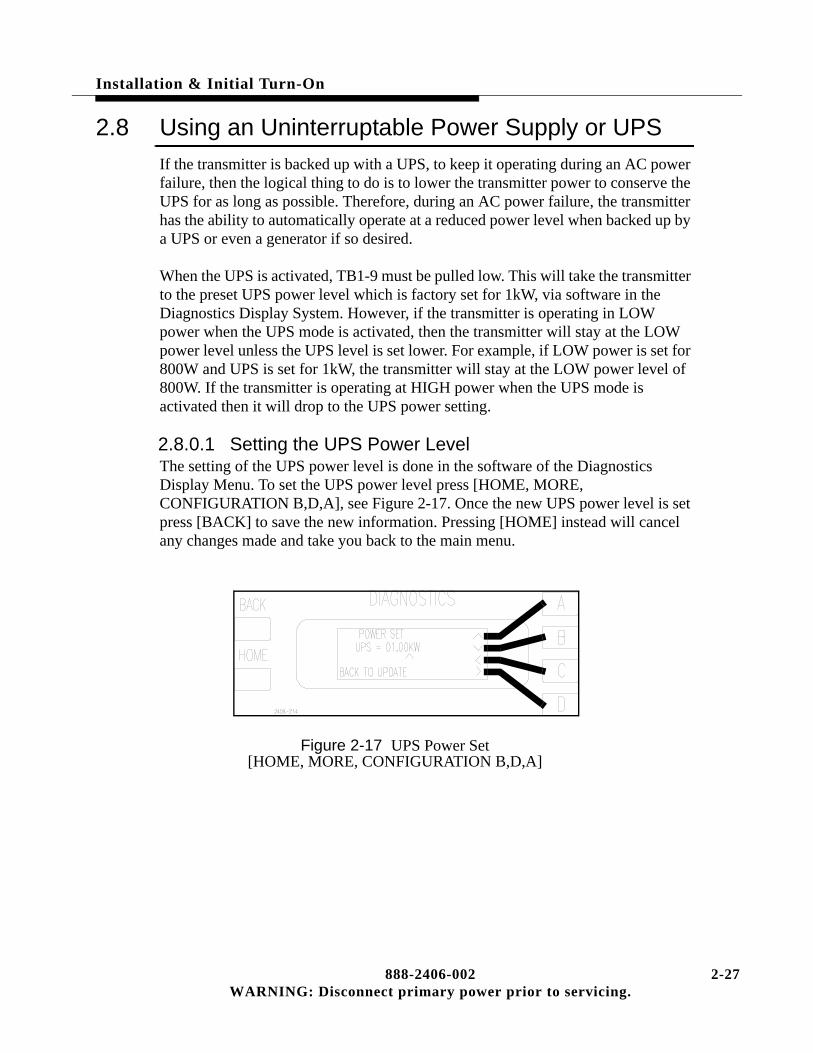
Installation & Initial Turn-On
2.8 Using an Uninterruptable Power Supply or UPS
If the transmitter is backed up with a UPS, to keep it operating during an AC power failure, then the logical thing to do is to lower the transmitter power to conserve the UPS for as long as possible. Therefore, during an AC power failure, the transmitter has the ability to automatically operate at a reduced power level when backed up by a UPS or even a generator if so desired.
When the UPS is activated, TB1-9 must be pulled low. This will take the transmitter to the preset UPS power level which is factory set for 1kW, via software in the Diagnostics Display System. However, if the transmitter is operating in LOW power when the UPS mode is activated, then the transmitter will stay at the LOW power level unless the UPS level is set lower. For example, if LOW power is set for 800W and UPS is set for 1kW, the transmitter will stay at the LOW power level of 800W. If the transmitter is operating at HIGH power when the UPS mode is activated then it will drop to the UPS power setting.
2.8.0.1 Setting the UPS Power LevelThe setting of the UPS power level is done in the software of the Diagnostics Display Menu. To set the UPS power level press [HOME, MORE, CONFIGURATION B,D,A], see Figure 2-17. Once the new UPS power level is set press [BACK] to save the new information. Pressing [HOME] instead will cancel any changes made and take you back to the main menu.
Figure 2-17 UPS Power Set[HOME, MORE, CONFIGURATION B,D,A]
888-2406-002 2-27WARNING: Disconnect primary power prior to servicing.

2-
Installation & Initial Turn-On
2.9 Optimizing Efficiency
The transmitter has the ability to Manually or Automatically optimize its own operating efficiency. It is not a requirement, and the transmitter will meet all specifications without activating this function. When activated, the controller will adjust the transmitter operating parameters to get the best possible efficiency. The user must select whether the function is in Manual or Automatic mode via the Diagnostics Display Menus. To select the mode press [HOME, MORE, CONFIGURATION A,D,D then A to Toggle: ON for Auto and OFF for Manual]. See Figure 2-18.
• Automatic Mode - When AUTO mode is selected, the transmitter will automati-cally optimize the efficiency every 12 hours unless there is an active fault present at the time it is supposed to be activated. Inactive faults in the Log will not pre-vent optimization. However, a power failure will reset the 12 hour counter. This is the recommended mode of operation and is the default mode from the factory. Optimization can also be done manually even with the Auto mode selected.
Figure 2-18 Auto Max Efficiency Configuration Screen[HOME, MORE, CONFIGURATION A,D,D]
• Manual Mode - If the optimization is set to OFF or Manual mode, then in the Diagnostics Display, under Configuration, there is a menu screen which can be used to optimize the transmitter efficiency. To manually optimize efficiency press [HOME, METERING D,C then D for Maximization]. See Figure 2-19.
Figure 2-19 Efficiency Metering Screen[HOME, METERING D,C]
28 888-2406-002WARNING: Disconnect primary power prior to servicing.

Installation & Initial Turn-On
NOTE:The REF VOLTAGE in Figure 2-19 is merely an internal reference point the controller uses to reduce the supply voltage in optimized mode. This reading is usually in the low 40’s when the transmitter is optimized (well below the actual supply voltage).
2.10 Setting the Low Power Alarm
The transmitter has a low power alarm output for a remote control system. The power level at which this remote alarm output is triggered, at TB1-13 XMTR_PWR_LO_IND, is selectable in the Configuration Menus. To set this power level press [HOME, MORE, CONFIGURATION B,D,B]. This should take you to the screen in Figure 2-20. Set the power level at which you want the alarm to become active and press [BACK] to save changes. For a complete listing of all configurable parameters see “System Configuration and Calibration” in Section VI, Troubleshooting.
Figure 2-20 Remote Low Power Alarm Set[HOME, MORE, CONFIGURATION B,D,B
2.11 Jumper Settings for Installation of a Harris Exciter
The following is for installing an exciter other than the one (or two) which came with the transmitter. Any exciter tested and shipped with the transmitter will have already been configured properly for the transmitter and should not require any jumper changes (Mounting kits are available for each of the exciters).
Table 2-2 includes all relevant jumper placement for the transmitter and the following exciters:
• Digit CD Exciter with 994-XXXX-004 part number.
• Digit Exciter with 994-XXXX-002 part number.
• SuperCiter
• THE-1
888-2406-002 2-29WARNING: Disconnect primary power prior to servicing.

2-
Installation & Initial Turn-On
Table 2-1 TB1 Remote Control Interface Connections
30 888-2406-002WARNING: Disconnect primary power prior to servicing.

Installation & Initial Turn-On
Table 2-1 TB1 Remote Control Interface Connections (continued)
888-2406-002 2-31WARNING: Disconnect primary power prior to servicing.
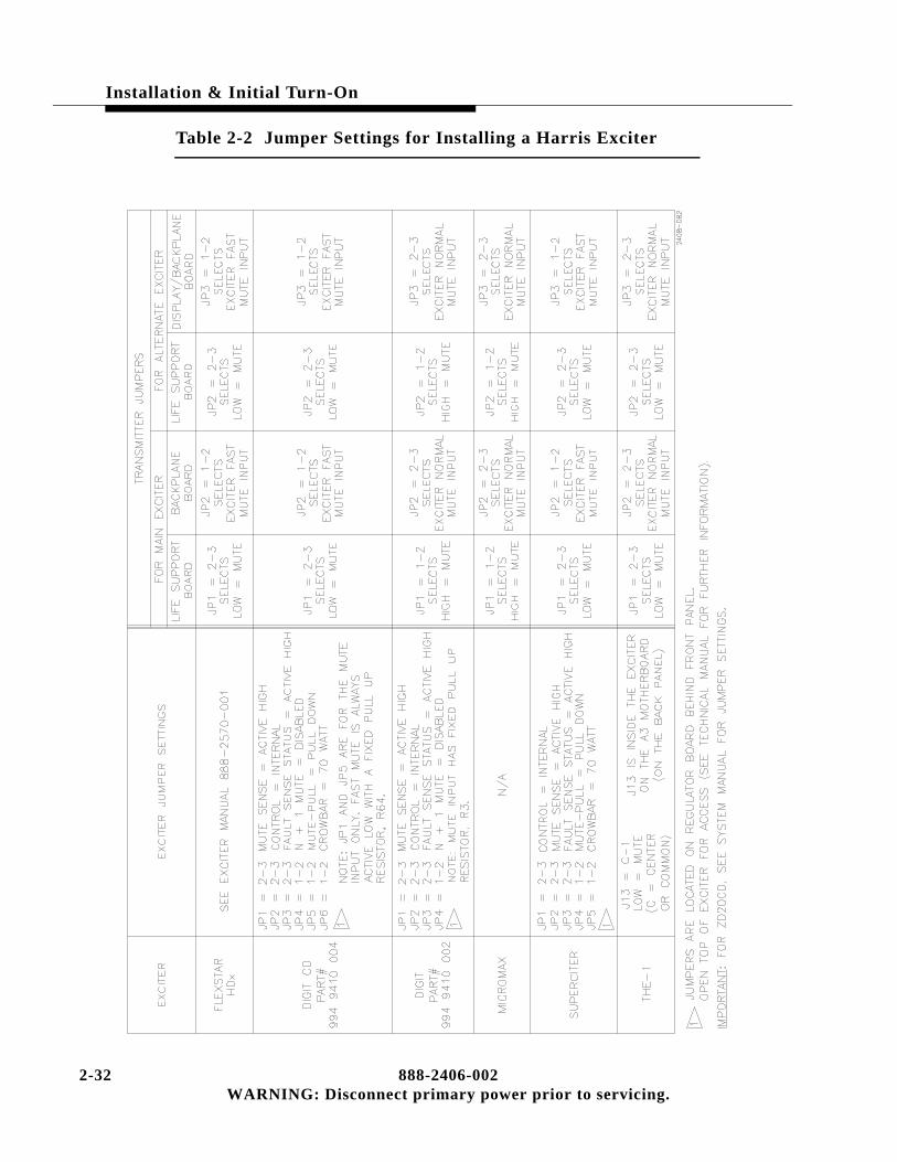
2-
Installation & Initial Turn-On
Table 2-2 Jumper Settings for Installing a Harris Exciter
32 888-2406-002WARNING: Disconnect primary power prior to servicing.

Installation & Initial Turn-On
2.12 Power Distribution for Optimum Transmitter Performance
This section is applicable to the three phase supplies only, as well as other three phase equipment. For many years HARRIS engineers have recommended that the three phase power distribution system should be either a closed delta or WYE configuration to provide better radio and television transmitter performance by helping prevent line unbalance. Operation with substantial voltage unbalance from line to line results in higher than normal signal-to-noise ratio in the transmitter output signal, increased three phase transformer heating, and hot three phase motors.
2.12.1 Overheating from Line UnbalanceEven a device as simple as a three phase motor should be operated from a power line in which the voltage is balanced within 1%. It takes only a 3.5% line unbalance to produce a 25% increase above normal temperature. A 5% unbalance will cause destructive temperature rises of 50% greater than normal!
Similar characteristics can be expected in the windings of a three phase power transformer down inside the cabinet of your transmitter. Transformers and motors can be designed with extra safety features where thermal rise is limited to acceptable levels; however, in this case, other transmitter parameters cannot be made acceptable at a reasonable cost.
2.12.2 Transmitter Noise PerformanceThe most difficult parameter to meet with power line unbalance is transmitter noise performance. Most large transmitters use six-phase or twelve-phase high voltage power supplies. The energy storage capacitors are expensive to install and large stored energies make destructive faults inevitable. A good design will have sufficient energy storage capacitors to meet the specified signal-to-noise but not much more. When the equipment is then operated from an unbalanced line, the power supply ripple frequency will be twice the line frequency instead of six to twelve times. It becomes obvious that it would take three times as much energy storage to achieve the original performance goal.
888-2406-002 2-33WARNING: Disconnect primary power prior to servicing.

2-
Installation & Initial Turn-On
2.12.3 The Causes of Line UnbalanceHow does a line unbalance occur? It is a rare case in which a large commercial power producer would generate unbalanced voltage, so we must look elsewhere in the system. When you have large single phase power users on a power line this can cause uneven distribution of the line currents in the system. Uneven currents through balanced impedances will result in line-to-line voltage unbalance.
Another likely source of this problem can come from unbalanced impedances in the power distribution system. Unbalanced impedance will always be seen when an “open” delta three phase distribution system is used. Transformer design textbooks clearly show that the voltage regulation of an unbalanced system is poor.
2.12.4 Three Phase Delta Distribution TransformersFigure 2-21 shows open and closed delta systems. The closed delta impedance looking into each terminal (A, B & C) is exactly the same; but this is not the case in the open delta configuration. Depending on the impedances of the transformers in the open delta circuit, line voltage unbalance sufficient to impair satisfactory operation of the overall transmitter may result. For this reason, along with their inherent susceptibility to transients, Harris does not recommend the use of open delta systems.
Figure 2-21 3 Phase Closed Delta vs. Open Delta
The only advantage of the open delta is lower initial cost, and this is partially offset by the fact that when only two transformers are used, they must be larger than the three transformers in a closed delta system.
Difficulties have often been experienced with open delta systems; but when a third transformer was added to close the delta, the problems disappeared.
34 888-2406-002WARNING: Disconnect primary power prior to servicing.
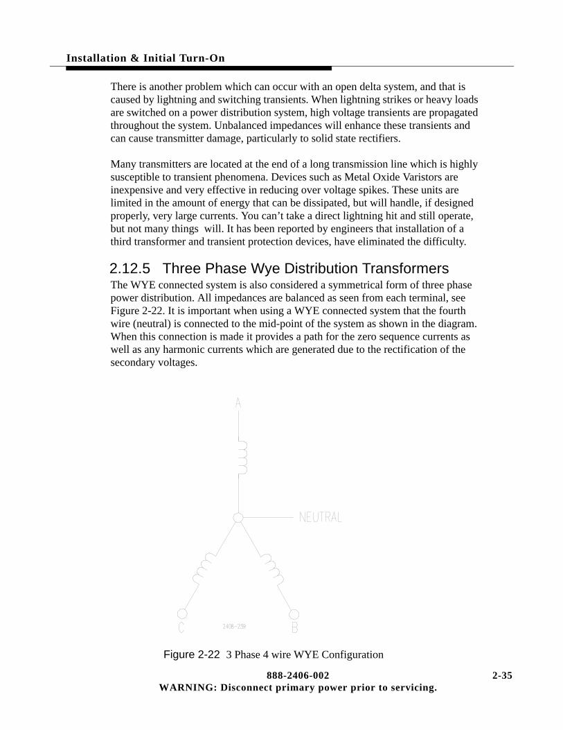
Installation & Initial Turn-On
There is another problem which can occur with an open delta system, and that is caused by lightning and switching transients. When lightning strikes or heavy loads are switched on a power distribution system, high voltage transients are propagated throughout the system. Unbalanced impedances will enhance these transients and can cause transmitter damage, particularly to solid state rectifiers.
Many transmitters are located at the end of a long transmission line which is highly susceptible to transient phenomena. Devices such as Metal Oxide Varistors are inexpensive and very effective in reducing over voltage spikes. These units are limited in the amount of energy that can be dissipated, but will handle, if designed properly, very large currents. You can’t take a direct lightning hit and still operate, but not many things will. It has been reported by engineers that installation of a third transformer and transient protection devices, have eliminated the difficulty.
2.12.5 Three Phase Wye Distribution TransformersThe WYE connected system is also considered a symmetrical form of three phase power distribution. All impedances are balanced as seen from each terminal, see Figure 2-22. It is important when using a WYE connected system that the fourth wire (neutral) is connected to the mid-point of the system as shown in the diagram. When this connection is made it provides a path for the zero sequence currents as well as any harmonic currents which are generated due to the rectification of the secondary voltages.
Figure 2-22 3 Phase 4 wire WYE Configuration
888-2406-002 2-35WARNING: Disconnect primary power prior to servicing.

2-
Installation & Initial Turn-On
Today, many transformers are supplied with all of the primary terminals available so that either a delta or WYE connection can be made. Table 2-4 shows the different line-to-line voltages that are available with this configuration.
In summary, both symmetrical power distribution systems are satisfactory because of their balanced impedances. Use either a closed delta or a four wire WYE system for maximum transmitter performance. Never use an open delta system just to cut costs - it could cost dearly in the long run.
Table 2-3 Typical Line Voltages, Delta or WYE
Delta ConnectedTransformer
WYE ConnectedTransformer
210 364
220* 380*
230 400
240* 415*
250 433
*Typical voltages in some areas of the world.
36 888-2406-002WARNING: Disconnect primary power prior to servicing.

Operator Guide
888-2406-002WARNING: Disconnect primary power prior
3
3.1 IntroductionThis section contains normal operational procedures and information pertaining to the function of the Platinum Z2 FM Transmitter. Most important, is the information regarding use of the Diagnostic System. All of the information in this section assumes the transmitter and controller are in proper working order.
Figure 3-1 Controller Front Panel
3-1 to servicing.

3-
Operator Guide
3.2 Transmitter Controls
The transmitter controls are mostly on the right half of the controller front panel at the top of the transmitter, See Figure 3-1. These controls and their function are listed below.
OFF - Used to turn the transmitter off
ON - HIGH - Turns the transmitter on to the previous HIGH setting. If the transmitter has folded back power automatically, due for instance to high VSWR, pressing the HIGH button will return the transmitter to the normal high power level provided the cause of the foldback is gone.
ON - LOW - Turns the transmitter on to the previous LOW setting. If the transmitter has folded back power automatically, due for instance to high VSWR, pressing the LOW button will return the transmitter to the normal low power level provided the cause of the foldback is gone.
POWER (up/down arrows) - used to raise and lower the transmitter power.
REMOTE DISABLE - (Located on the left side of the controller) used to disable any remote control system which is connected to the transmitter. When the LED is lit, the remote control inputs are disabled.
NOTE:Some of the less often used transmitter controls, such as calibration and con-figuration, are located in the menu screens of the Diagnostics system. These are covered as part of the Diagnostics system later in this section.
2 888-2406-002WARNING: Disconnect primary power prior to servicing.

Operator Guide
3.3 Transmitter Metering
There are five function keys below the Transmitter display on the front of the controller:
1. FWD PWR (Forward Power)
2. RFL PWR (Reflected Power)
3. PA Amps
4. PA Volts
5. APC (Automatic Power Control)
These are dedicated metering selections for the 5 most important transmitter parameters. The Diagnostic Display will provide all other necessary metering, while still being able to monitor these five readings.
3.3.1 Forward Power (FWD PWR) Units of MeasureThe default unit of measure for the forward power reading is percentage, with 100% representing the nominal power output for the station. This percentage can be calibrated to any power level using the Configuration controls in the Diagnostics System. If desired, the forward power reading can be converted to kilowatt by simply pressing and holding the FWD PWR button for at least 3 seconds. After 3 seconds the display should automatically change to power in kilowatts.
3.3.2 Reflected Power (RFL PWR) Units of MeasureThe default unit of measure for reflected power is VSWR. If desired, the reflected power reading can be converted to kilowatt by simply pressing and holding the RFL PWR button for at least 3 seconds. After 3 seconds the display should automatically change to power in kilowatts.
888-2406-002 3-3WARNING: Disconnect primary power prior to servicing.
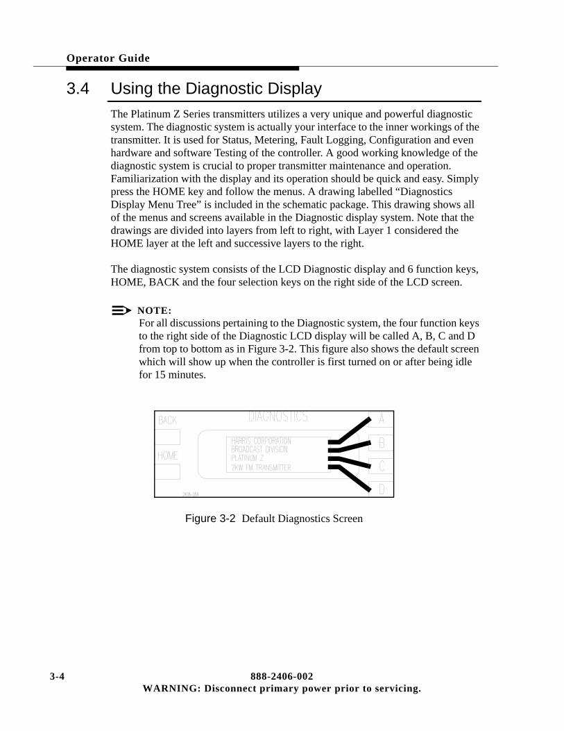
3-
Operator Guide
3.4 Using the Diagnostic Display
The Platinum Z Series transmitters utilizes a very unique and powerful diagnostic system. The diagnostic system is actually your interface to the inner workings of the transmitter. It is used for Status, Metering, Fault Logging, Configuration and even hardware and software Testing of the controller. A good working knowledge of the diagnostic system is crucial to proper transmitter maintenance and operation. Familiarization with the display and its operation should be quick and easy. Simply press the HOME key and follow the menus. A drawing labelled “Diagnostics Display Menu Tree” is included in the schematic package. This drawing shows all of the menus and screens available in the Diagnostic display system. Note that the drawings are divided into layers from left to right, with Layer 1 considered the HOME layer at the left and successive layers to the right.
The diagnostic system consists of the LCD Diagnostic display and 6 function keys, HOME, BACK and the four selection keys on the right side of the LCD screen.
NOTE:For all discussions pertaining to the Diagnostic system, the four function keys to the right side of the Diagnostic LCD display will be called A, B, C and D from top to bottom as in Figure 3-2. This figure also shows the default screen which will show up when the controller is first turned on or after being idle for 15 minutes.
Figure 3-2 Default Diagnostics Screen
4 888-2406-002WARNING: Disconnect primary power prior to servicing.

Operator Guide
3.4.1 HOMEHOME takes you to the home layer or root menu. This menu should look like the one in Figure 3-3, which is the first of two screens in this layer. The second screen in the HOME layer is accessed by pressing the “D” function key to the right of the display which is labelled “MORE -” on the display. The screen should now look like Figure 3-4. These two screens give access to all six HOME menus:
• Status
• Metering
• Fault
• Configuration
• Test
• Software Revision
Figure 3-3 Home Menu Page 1
Figure 3-4 Home Menu Page 2
888-2406-002 3-5WARNING: Disconnect primary power prior to servicing.

3-
Operator Guide
3.4.2 BACKBACK takes you to the previous layer in the menu tree, not necessarily to the previous screen. As an example, if you were to press HOME and then choose STATUS you would now be in layer 2 of the STATUS menu. You should see the screen shown in Figure 3-5. If you press MORE, you go the second screen in layer 2. Now press the BACK key. Notice that it did not take you to the previous screen but back to Layer 1, the HOME layer, shown in Figure 3-3. However, if instead of pressing BACK, you pressed more again, this would have taken you to the first screen in layer 2 (since there are only two screens).
Figure 3-5 Status Layer 2, Page 1
3.4.3 MOREMORE is a menu item which is used when there are more menu items on a layer than will fit on one screen. It will take you to the next screen in the same layer. When you have reached the last screen in that layer, pressing MORE again will take you back to the first screen in that layer. This is shown on the Diagnostics Display Menu Tree drawings.
6 888-2406-002WARNING: Disconnect primary power prior to servicing.

Operator Guide
3.4.4 Diagnostic CodesFor ease of discussion a simple code will be used to guide you to the area or screen being discussed. The code will have the name of one of the HOME menu items listed above, followed by the appropriate A, B, C or D function key presses required to get to the screen being discussed. The code will always be enclosed in brackets [x,x,x].
NOTE:It will be assumed that you always press the HOME key first before entering the key sequences in the brackets.
Example 1 If you wanted to check the temperature of the individual Power Amplifiers, you would press the following keys;
[HOME, METERING C,A,C]
After entering this key sequence the screen should look like Figure 3-6. This is equivalent to pressing the following menu items as they appear on each successive screen:
METERING, TEMPERATURE, PA
Figure 3-6 PA Temperature Metering[HOME, METERING C,A,C]
888-2406-002 3-7WARNING: Disconnect primary power prior to servicing.

3-
Operator Guide
Example 2 You want to check or possibly change the Maximum High Power Setting. This falls under the category of CONFIGURATION, but this menu item only shows up on the second screen of the HOME layer. Therefore, press the following keys:
[HOME, MORE, CONFIGURATION B,B]
This should have taken you to the screen shown in Figure 3-7. This screen now allows the operator to change the Maximum High Power setting using the A,B,C and D function keys. Pressing the BACK key updates the change, while pressing HOME would cancel any changes.
Figure 3-7 Max High Power Configuration Screen[HOME, MORE, CONFIGURATION B,B]
3.4.5 Asterisk and Pound Signs(*, #)The asterisk and the pound sign characters are used in some of the metering menus of the Diagnostics Display. If an asterisk (*) shows up in a metering menu, it means that there is no data being received for that reading. The pound sign will only be used in the Vg (Gate Control Voltage for the individual PAs) menus and signifies that there has been a crossover (this is a condition where one PA Controller crosses over and mutes the PAs associated with another PA Controller).
8 888-2406-002WARNING: Disconnect primary power prior to servicing.
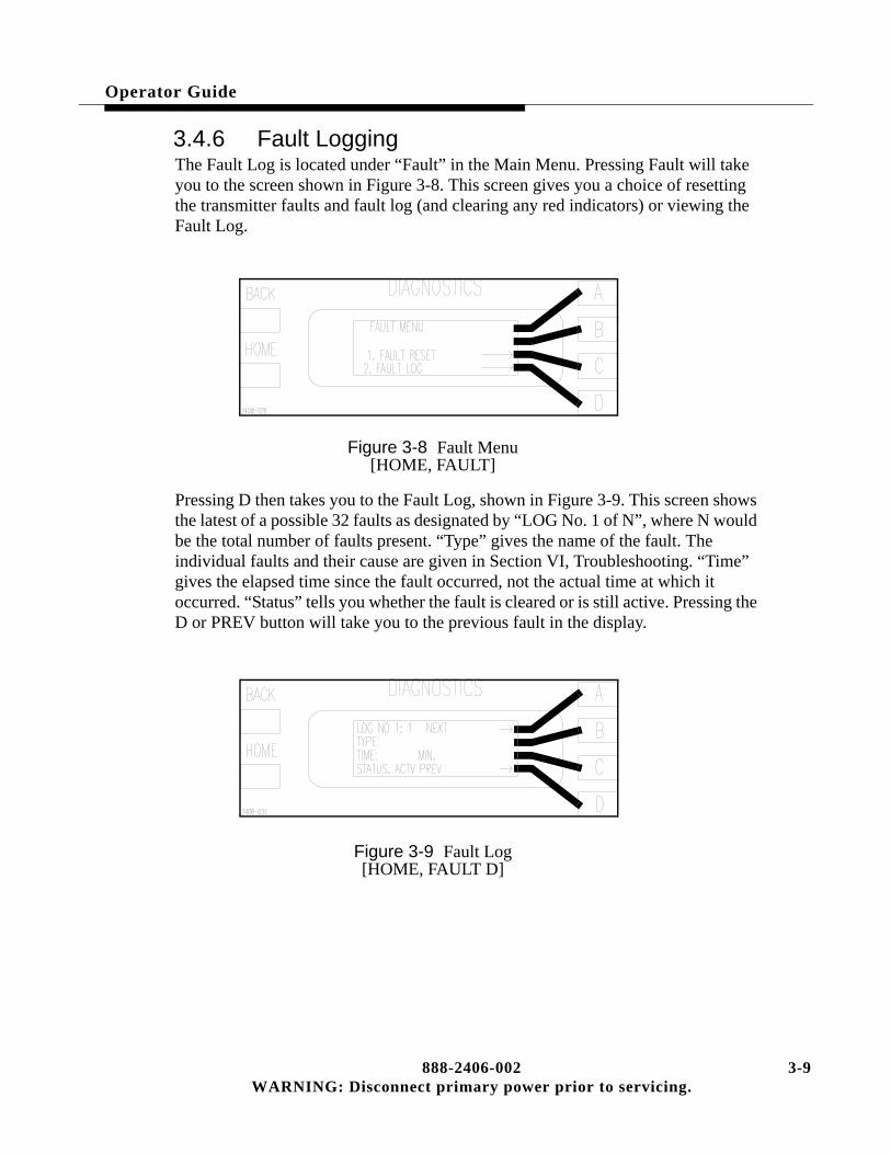
Operator Guide
3.4.6 Fault LoggingThe Fault Log is located under “Fault” in the Main Menu. Pressing Fault will take you to the screen shown in Figure 3-8. This screen gives you a choice of resetting the transmitter faults and fault log (and clearing any red indicators) or viewing the Fault Log.
Figure 3-8 Fault Menu[HOME, FAULT]
Pressing D then takes you to the Fault Log, shown in Figure 3-9. This screen shows the latest of a possible 32 faults as designated by “LOG No. 1 of N”, where N would be the total number of faults present. “Type” gives the name of the fault. The individual faults and their cause are given in Section VI, Troubleshooting. “Time” gives the elapsed time since the fault occurred, not the actual time at which it occurred. “Status” tells you whether the fault is cleared or is still active. Pressing the D or PREV button will take you to the previous fault in the display.
Figure 3-9 Fault Log[HOME, FAULT D]
888-2406-002 3-9WARNING: Disconnect primary power prior to servicing.

3-
Operator Guide
3.5 Emergency Operating Procedures
! WARNING:THE PA MODULES ARE DESIGNED TO HANDLE VERY HIGH TEMPERATURES AND MAY BE EXTREMELY HOT. DO NOT TOUCH THE MODULES WITH BARE HANDS AFTER THE TRANSMITTER HAS BEEN RUNNING, ESPECIALLY IN HIGH AMBIENT TEMPERATURE ENVIRONMENTS.
3.5.1 Multiple PA Failures in a FoursomeIf two PAs were to fail in a single group of four or Foursome, the resulting system imbalance would result in a power foldback to approximately 50% of nominal power output. Since a single PA failure in a foursome does not create an imbalance severe enough to cause foldback, one of the PA modules with a bad PA should be taken out and swapped for one of the modules on the opposite side of the transmitter, placing the PA in a different foursome. For example, if PA amplifiers B1 and B2 have failed (these are in the front of the transmitter), pull out the B2 PA module, and swap it with any of the PA modules in the rear of the transmitter such as B5. There are still 2 failed PAs, B1 and B5, but now each one is in a different foursome. This will restore balance to the system and the transmitter will still be able to operate at near full power output by automatically increasing the drive to the remaining PAs (via the APC voltage).
For more information on Foursomes refer to Section IV, Overall System Theory, under the heading “8-Way Combiner”.For quick reference, the foursome groupings are as follows:
(See Figure 4-5 and Figure 4-5 on page 4-11, in Section IV)
• B1, B2, B3 and B4 - Front Foursome
• B5, B6, B7 and B8 - Rear Foursome
10 888-2406-002WARNING: Disconnect primary power prior to servicing.

Operator Guide
3.6 Manual Exciter Switching
The active exciter (if dual exciters are installed) can be switched manually from the Status menus in the Diagnostics Display. To manually switch from Exciter 1 to Exciter 2 press [STATUS D,C]. This will bring up the screen shown in Figure 3-10. Pressing [D] will toggle between the two Exciters.
Figure 3-10 Exciter Status Screen[HOME, STATUS D,C]
3.7 Manual IPA Switching
The active IPA can be switched manually from the Status menus in the Diagnostics Display. To manually switch from IPA_1 to IPA_2 press [STATUS D,B]. This will bring up the screen shown in Figure 3-11. Pressing [D] will toggle between the two IPAs.
Figure 3-11 IPA Status Screen[HOME, STATUS D,B]
888-2406-002 3-11WARNING: Disconnect primary power prior to servicing.

3-
Operator Guide
3.8 Optimizing Efficiency
The transmitter has the ability to Manually or Automatically optimize its own operating efficiency. It is not a requirement, and the transmitter will meet all specifications without activating this function. When activated, the controller will adjust the transmitter operating parameters to get the best possible efficiency. The user must select whether the function is in Manual or Automatic mode via the Diagnostics Display Menus, see Figure 3-12. To select the mode press [HOME, MORE, CONFIGURATION A,D,D then A to toggle: ON for Auto mode or OFF for Manual mode].
• Automatic Mode - When AUTO mode is selected, the transmitter will automati-cally optimize the efficiency every 12 hours unless there is an active fault present at the time it is supposed to be activated. Inactive faults in the Log will not pre-vent optimization. However, a power failure will reset the 12 hour counter. This is the recommended mode of operation and is the default mode from the factory. Optimization can also be done manually even with the Auto mode selected.
Figure 3-12 Max Efficiency Configuration Screen[HOME, MORE, CONFIGURATION A,D,D]
• Manual Mode - If the optimization is set to OFF or Manual mode, then in the Diagnostics Display, under Configuration, there is a menu screen which can be used to optimize the transmitter efficiency. To optimize efficiency press [METERING D,C then D for Maximization]. The screen is shown in Figure 3-13.
Figure 3-13 Efficiency Metering Screen[METERING D,C]
12 888-2406-002WARNING: Disconnect primary power prior to servicing.
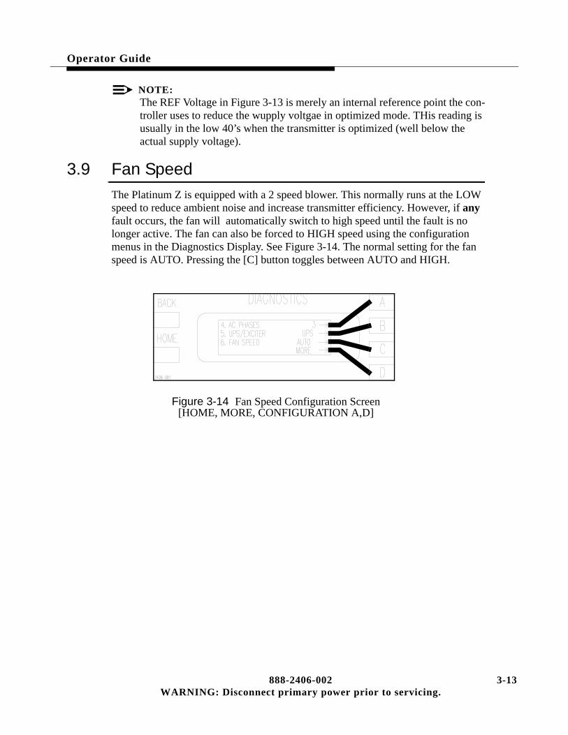
Operator Guide
NOTE:The REF Voltage in Figure 3-13 is merely an internal reference point the con-troller uses to reduce the wupply voltgae in optimized mode. THis reading is usually in the low 40’s when the transmitter is optimized (well below the actual supply voltage).
3.9 Fan Speed
The Platinum Z is equipped with a 2 speed blower. This normally runs at the LOW speed to reduce ambient noise and increase transmitter efficiency. However, if any fault occurs, the fan will automatically switch to high speed until the fault is no longer active. The fan can also be forced to HIGH speed using the configuration menus in the Diagnostics Display. See Figure 3-14. The normal setting for the fan speed is AUTO. Pressing the [C] button toggles between AUTO and HIGH.
Figure 3-14 Fan Speed Configuration Screen[HOME, MORE, CONFIGURATION A,D]
888-2406-002 3-13WARNING: Disconnect primary power prior to servicing.

3-
Operator Guide
14 888-2406-002WARNING: Disconnect primary power prior to servicing.
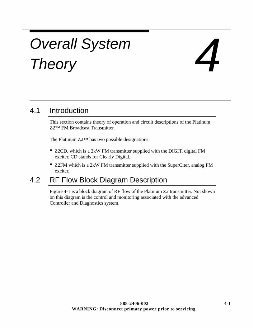
Overall System Theory
888-2406-002WARNING: Disconnect primary power prior
4
4.1 IntroductionThis section contains theory of operation and circuit descriptions of the Platinum Z2™ FM Broadcast Transmitter.
The Platinum Z2™ has two possible designations:
• Z2CD, which is a 2kW FM transmitter supplied with the DIGIT, digital FM exciter. CD stands for Clearly Digital.
• Z2FM which is a 2kW FM transmitter supplied with the SuperCiter, analog FM exciter.
4.2 RF Flow Block Diagram Description
Figure 4-1 is a block diagram of RF flow of the Platinum Z2 transmitter. Not shown on this diagram is the control and monitoring associated with the advanced Controller and Diagnostics system.
4-1 to servicing.

4-
Overall System Theory
Figure 4-1 RF Flow Block Diagram
2 888-2406-002WARNING: Disconnect primary power prior to servicing.
Overall System Theory
4.2.1 ExcitersIt starts with the built in dual exciter option (in other words the switching components are present but the exciter is optional). The RF output of both exciters (if present) connect in to the Exciter/IPA Backplane board. The exciter RF switch shown on this board is activated by the controller if Exciter A were to fail, placing Exciter B on the air automatically. This fault and all other transmitter faults are stored in the Fault Log in the Diagnostics Display System. The active exciter output is selected by the first RF switch and directed to the active IPA by the second RF switch. Both RF switches are controlled by the Master Controller.
4.2.2 IPAsThe Z2 has 1 IPA Module, which is made up of 2 power amplifiers or PAs. The IPA Module is not interchangeable with the PA Modules since the PA modules for the Z2 only have one amplifier on one side of the heatsink. The 2 IPAs per IPA Module operate in Main/Alternate mode, meaning that only one of them is active at a time. The block diagram shows that IPA_1 is the normally active amplifier. RF switching on the input and output of the IPA is activated by the controller if a fault is sensed in the active IPA. The IPA output passes through a hybrid with a shorting cable connected across the output terminals. The hybrid reject load output then becomes the IPA output to the PA.
4.2.3 Power AmplifierThe Z2 contains only one Z-Plane (called Z-Plane B) which could be considered a 2.5kW Power Block. The Z-Plane can be broken down into 2 parts, a Divider Board and a Combiner Board.
4.2.3.1 Z-Plane Divider BoardThe Divider Board takes the IPA input and uses a 2 way wilkinson splitter to drive two more 4 way Wilkinson splitters. This provides the necessary 8 drive signal for the 8 PAs connected to the Z-Plane. The PAs are labeled 1-8. PAs 1-4 are located in the front of the transmitter, while 5-8 are located in the rear of the transmitter. PAs 1-4 are considered a FOURSOME, because they are connected to the same 4 Way combiner. PAs 5-8 are also considered a Foursome. (See Figure 4-4 and Figure 4-5)
888-2406-002 4-3WARNING: Disconnect primary power prior to servicing.

4-
Overall System Theory
4.2.3.2 Z-Plane Combiner BoardThe Combiner Board receives the outputs from the 8 PAs and combines them in two 4 Way Isolated Wilkinson Combiners, whose outputs are then combined in a 2 way Wilkinson combiner for a 2.5kW nominal output. Each PA is capable of delivering up to 425 watts into a good load, but will be operating at approximately 325 watts nominally for 2kW of combined transmitter output. The isolation loads for all 3 combiners are located on another board called the Isolation Board for better heat dissipation and easier access. The Isolation board is located on the side of the Power Block nearest the center of the transmitter. The Isolation Board also contains RF switches which can switch out a faulty PA without causing a severe system imbalance, allowing greater redundancy. This also allows the PA Modules to be HOT-PLUGGABLE, meaning that a PA module may be removed while the transmitter is operating. Interlock pins on the module connectors mute the PAs before it switches out the unplugged module.
4.2.4 RF outputThe 2.5kW output from the Z-Plane passes through an aluminum box under the PA (in the Power Supply Compartment) and connects to the transmission line Harmonic Filter at the top rear of this box. The harmonic filter connects to the output flange on the top rear of the transmitter. The Harmonic Filter has 3 directional couplers. One is for Forward Power, one is for Reflected Power and the third is left available for on site use as a Demodulator or analyzer sample. The couplers are designed for at least 30dB directivity.
4 888-2406-002WARNING: Disconnect primary power prior to servicing.

Overall System Theory
4.3 Detailed RF Theory of Operation
The exciter theory is described in a separate technical manual included with the transmitter. Each of the remaining RF sections of the transmitter are described in the following paragraphs.
4.3.1 Exciter OperationThe exciter output is basically fixed and should not require adjustment. The exciter power output is set using the controls on the front of the exciter and should be set to the “Exciter Power” reading on the factory test data sheet for the transmitter. For information on setting exciter power, refer to the exciter manual.
4.3.1.1 Automatic Exciter SwitchingIf a second or backup exciter is installed and the on air exciter fails, the controller will automatically switch to the backup exciter and log the fault. Note that the controller will wait 10 seconds for the on-air exciter to recover before switching to the backup. If a backup exciter is added anytime after factory testing, the installer must go into the Configuration Menus on the Diagnostic Display and set “ALT EXCITER” to YES to let the controller know that the backup exciter exists. If this is not done the controller will not auto switch.
4.3.1.2 Manual Exciter SwitchingFor dual exciter configurations, the on-air exciter can be selected manually using the Exciter Status Screen in the Diagnostics Display [STATUS D,C] see Figure 4-2. Manual exciter switching can also be done via the configurable remote input. See Table 2-1 in Section II for more information on this remote control input.
Figure 4-2 Exciter Status and Manual Switch Screen[HOME, STATUS D,C]
888-2406-002 4-5WARNING: Disconnect primary power prior to servicing.

4-
Overall System Theory
4.3.2 IPAThe IPA amplifier and/or module is identical to any one of the PA modules except that it has an amplifier on each side of the module whereas the PA modules only have a single PA mounted on the module heatsink (the opposite side is empty). This allows a PA module to be used in place of a failed IPA. The standard IPA configuration includes dual IPA amplifiers, used in a main/alternate configuration (in other words only one is used at a time). If one of the IPA amplifiers fails, the controller will automatically switch to the second IPA with a minimal interruption of service. For a detailed explanation of the RF amplifier operation refer to the paragraph “Power Amplifier” later in this section.
4.3.2.1 IPA Power OutputThe power output of the IPA determines the power output of the transmitter and is varied by changing the gate bias on the IPA amplifiers MOSFETs. The gate bias for the IPA is adjusted by the controller, specifically the Master Controller Board, using the front panel “POWER” Raise and Lower controls.
4.3.2.2 IPA Power SupplyThe IPA power supply is +52 volts from the PA power supply. The +52Vdc is connected to the IPA(s) via the IPA Backplane Board. If the transmitter is configured with the optional Dual Power Supply Configuration, the +52Vdc for the IPA is diode OR’ed from both supplies for redundancy.
4.3.3 IPA BackplaneRefer to the IPA Backplane schematic for the following. The IPA module plugs into the IPA Backplane Board. This board interfaces all inputs and outputs for the IPA module. It is also responsible for:
a. Main/Alternate exciter switching (only active with dual exciter configura-tion).
b. Main/Alternate IPA switching (active with standard, dual IPA configuration).
c. Monitoring of IPA temperature, voltage, current and forward power.
d. Air flow sensing
e. Ambient temperature sensing
f. IPA 1 and IPA 2 interlocking
6 888-2406-002WARNING: Disconnect primary power prior to servicing.

Overall System Theory
4.3.3.1 Main/Alternate Exciter SwitchingExciter selection is done via relay K1 and the EXCITER SELECT control signal from the Life Support Board. The EXCITER SELECT signal is normally low which places K1 in the position shown on the schematic, sending the Exciter 1 RF output to the IPA input relay K2. If EXCITER SELECT goes high, K1 will be energized and switches to the Exciter 2 RF output. This switching will take place automatically if an exciter fault is detected by the Master Controller board. Exciter switching can also be done manually using the Diagnostics display. Press [HOME, STATUS D,C] (this code is explained in Section III, Operation). This should bring up the screen in Figure 4-2. Pressing the D function key will now toggle K1, switching from exciter 1 to exciter 2 or vise versa.
NOTE:For easy navigation through the Diagnostic menus, refer to “Using the Diag-nostic Display” in Section III, Operation and to the“Diagnostics Display Menu Tree”, in the schematic package, which gives a complete overview of the Diagnostics menu structure.
4.3.3.2 Main/Alternate IPA SwitchingSelection of IPA_1 or IPA_2 (both input and output) is done via relays K2, K3 and the IPA DRIVER SELECT control signal from the Life Support Board.
K2 switches the input RF drive from the exciter to IPA_1 or IPA_2 while K3 selects the active IPA RF output. The control signal, IPA DRIVER SELECT, is normally low which places K2 and K3 in the IPA_1 position as shown on the schematic. If IPA DRIVER SELECT goes high, K2 and K3 will be energized and switch to the IPA_2 position. If the Master Controller detects a loss of RF output from the active IPA it will automatically switch to the second IPA. IPA switching can also be done manually using the Diagnostics display. Press [HOME, STATUS D,B] This should bring up the screen in Figure 4-3. Pressing the D function key will now toggle K2 and K3, switching from IPA_1 to IPA_2 or vise versa.
Figure 4-3 IPA Status and Manual Switch Screen[HOME, STATUS D,B]
888-2406-002 4-7WARNING: Disconnect primary power prior to servicing.

4-
Overall System Theory
4.3.3.3 IPA MonitoringThe IPA Backplane Board provides for monitoring and/or interfacing of 4 main IPA parameters:
• IPA temperature (VTEMP_IPA1 and/or VTEMP_IPA2). If the IPA board exceeds 100°C, the controller will mute the transmitter and/or switch to the alternate IPA. The sensor is actually located on the IPA board, but is interfaced through the Backplane.
• IPA supply voltage (Vd_IPA_SAMPLE). A monitoring sample is sent to the con-troller through fuse F2. The Supply voltage for the IPA is diode or’ed from both PA supplies for redundancy.
• IPA current (Id_IPA). IPA current is measured by measuring the voltage drop across the series resistor R1. IPA current fault threshold is set at 14.3 amps.
• IPA Forward Power (IPA FWD PWR). A sample of the IPA forward power is taken by the directional coupler (shown right after K3 on the schematic) and detected by CR1. The DC voltage at TP1 will therefore be relative to the IPA out-put. This is also sent to the controller for monitoring and main/alternate IPA switching.
4.3.3.4 Air flow sensing.Airflow is sensed as the difference in temperature between a heated sensor, RT1, and an ambient sensor, RT2. RT1 is actively biased via R3 which will cause a steady increase in temperature with no air flow. Under normal operation, the voltage difference between the two sensor outputs will stabilize at some value depending on the amount of air flow. If the airflow is reduced or non-existent, then RT1 will heat up increasing its voltage output, whereas RT2 will stay the same. Eventually the voltage difference between the two sensors will reach a threshold where the controller will turn the fan to high speed to compensate for the reduced airflow. If the airflow is still insufficient, the transmitter will be shut off.
4.3.3.5 IPA_1 and IPA_2 interlocking.The signals IPA1_PCB_OK and IPA2_PCB_OK are the interlock signals for the IPA boards. The interlock connections on the IPA board (and the PAs as well) are shorter than the other pins. This causes the interlock connection to break before the RF and voltage contacts when the module is unplugged. This gives the controller time to shut off the IPAs (via the IPA gate voltage, IPA1_GATE) so that the connector contacts do not arc. However, it is not recommended that the IPA be removed without shutting the transmitter off first.
8 888-2406-002WARNING: Disconnect primary power prior to servicing.

Overall System Theory
4.3.3.6 IPA Power Divider (3dB Hybrid)The IPA power divider is actually a 3dB hybrid which is used in the Z5 and Z10 transmitters to split the IPA output into 2 equal amplitude signals 90 degrees out of phase to drive Z Planes A and B. In the Z2, only Z-Plane B is used and the hybrid is not really necessary. However, for ease of manufacturing the same IPA backplane is used in all Z series transmitters and the hybrid must be used. To make the hybrid transparent to the system a shorting cable is placed between the two normal outputs. This presents an infinite VSWR to the hybrid and all of the IPA power output is sent to the reject port which is now used as the hybrid output to Z-Plane B (the PA).
4.3.4 Z-Plane Combiner/Divider BoardsThere is only one Z-Plane Combiner/Divider Board in the Z2 transmitter. The board provides all inputs to and outputs from the PA modules. The Z Plane is the overall term for the combination of the Combiner and Divider board. There is a separate schematic for each part of the Z Plane in the schematic package. The first page of each schematic is identical and is a block diagram of the entire Z Plane.
The Z-Plane assembly contains:
• Edge connectors for 8 PA amplifier boards (4 in front and 4 in the rear). These connectors are labeled J1-J8.
• An 8 way Wilkinson Divider, driven by the IPA, which feeds RF drive to each of the 8 PA amplifiers.
• An 8 way Wilkinson Combiner which combines the output of the same 8 PA amplifiers.
The RF output of the Z-Plane board connects directly to the harmonic filter.
4.3.4.1 8-Way DividerRefer to the Divider schematic for the following. The 8-Way Divider is a 2-stage Wilkinson divider. The 8 way divider is located on the Z-plane board in the center of the PA assembly.
The input to the divider is first divided into two equal outputs at approximately 35 ohms by a two-way Wilkinson divider with a 70.7 ohm isolation resistor, R9. Each of these outputs (each end of R9) is then divided into 4 outputs in a 4-way Wilkinson divider.
The Wilkinson dividers contain terminating resistors which dissipate no power when all of the outputs are correctly loaded, but if a PA is removed, resulting in an open-circuit on an output, the Wilkinson circuit and the load resistors act to keep the input impedance of the splitter near the nominal value of 50 ohms. The 8 outputs from the two 4-Way Dividers are fed to the input of the 8 PA Amplifier boards,at J1 - J8.
888-2406-002 4-9WARNING: Disconnect primary power prior to servicing.

4-
Overall System Theory
4.3.4.2 8-Way CombinerRefer to the Combiner schematic for the following. Each 8-way combiner consists of two 4-way Wilkinson combiners, called FOURSOMES, followed by a 2-way Wilkinson combiner which combines the outputs of the two Foursomes. The Foursomes are split up as follows:
• 1, 2, 3 and 4 - Front Foursome
• 5, 6, 7 and 8 - Rear Foursome
The Wilkinson combiners include isolation loads (ISO loads) which dissipate no power if all PA outputs are equal and in phase. These resistors are located on the Isolation Board and labeled R1-R8. The ISO resistors connect to the points labeled E1-E8 on the Combiner schematic. If any input is lost due to failure of a PA module, the associated ISO load dissipates some power, approximately 150 watts, until the RF switch on the Isolation board disconnects the ISO load and grounds that point (E1-E8) on the combiner. This now looks like an open to the 4-way combiner output at E9 or E10 (the input to the 2-way combiner).
4.3.4.3 PA ModulesEach of the 8 PA Modules contain one PA Amplifier board mounted on one side of the PA Module heat sink, with the opposite side empty. The modules are numbered 1 through 8 with the top module in the front being #1 and counting to #4 at the bottom. The top rear module is #5 counting down to #8 at the bottom rear, see Figure 4-4 for the front view and Figure 4-5 for the rear view. All DC, signal and RF connections to a PA board are through one edge connector.
10 888-2406-002WARNING: Disconnect primary power prior to servicing.

Overall System Theory
Figure 4-4 PA Compartment Front View
Figure 4-5 PA Compartment Rear View
IPA_1
IPA_2
#1#2#3
#4
#5
#6
#7
#8
888-2406-002 4-11WARNING: Disconnect primary power prior to servicing.

4-
Overall System Theory
4.3.4.4 Power Amplifier (PA)The RF drive from the IPA enters the PA Amplifier Boards at Pin C. The RF input level for each amplifier is typically 15-20 watts. TL1, C1 and C2 allow the input impedance to be matched to 50 ohms and permit the phase shift through the module to be trimmed to a nominal value which allows all modules to combine in-phase. The RF signal is then sent to T1, a coaxial 9:1 transformer which also splits the phase providing 0 degree and 180 degree outputs to drive a pair of push-pull RF power MOSFETs (Q1 and Q2). Bias to Q1 and Q2 (labeled VG for Gate Voltage) is connected through the center of the secondary winding of T1.
The control voltage input called VG can be thought of as a bias voltage which can be used to vary the amplifier output. Normally for the PAs it is simply used to turn the amplifiers on and off. If VG is -18V the amplifier is off or muted. If VG is 0V the amplifier is fully turned on and drive level from the IPA determines the amplifier power output.
When the amplifier is used as the IPA, VG is used to linearly vary the IPA output which then controls the transmitter power output. For an IPA, VG comes from the Life Support Board and is controlled by the APC loop on the Master Controller Board. Pressing the RAISE and LOWER controls on the front of the transmitter will vary the APC voltage which in turn will vary VG to the IPAs. This will vary the IPA RF output, which will raise or lower transmitter power.
The MOSFET outputs are combined in T2, a 1:4 transformer as shown in Figure 4-6. C19 and C20 fine-match the 50 ohm load impedance at the PA output to the output impedance of T2. The +52Vdc or VD (Drain Voltage) from the main power supply enters at location C-1 and is decoupled and filtered by C11, C12, C13, C14, C16, C24, L1 and L2. The DC voltage reaches the drain of MOSFETs Q1 and Q2 through the center tap of T2’s primary winding. The advantage of this method is to allow direct DC connection to the MOSFETs and have an AC RF output through the coax without the need for a blocking capacitor.
Figure 4-6 PA Simplified Block Diagram
12 888-2406-002WARNING: Disconnect primary power prior to servicing.
Overall System Theory
Maximum RF output is 425 watts. Typical output level is 300 to 340 watts. The power module is designed for single amplifier field replacement. In the event an RF power MOSFET fails, field replacement is not practical due to the cost of components, time and test equipment involved in repair and alignment of phase, gain and response. This is a highly critical area, and if not done correctly, improper module and transmitter operation will occur.
As an additional consideration, please observe the following warning from the MOSFET manufacturer regarding beryllium oxide.
! WARNING:PRODUCT AND ENVIRONMENTAL SAFETY-TOXIC MATERIALS. THIS PRODUCT CONTAINS BERYLLIUM OXIDE. THE PRODUCT IS ENTIRELY SAFE PROVIDED THAT THE BEO DISC IS NOT DAMAGED. ALL PERSONS WHO HANDLE, USE OR DISPOSE OF THIS PRODUCT SHOULD BE AWARE OF ITS NATURE AND OF THE NECESSARY SAFETY PRECAUTIONS. AFTER USE, DISPOSE OF AS CHEMICAL OR SPECIAL WASTE ACCORDING TO THE REGULATIONS APPLY-ING AT THE LOCATION OF THE USER. IT MUST NEVER BE THROWN OUT WITH THE GENERAL OR DOMESTIC WASTE.
Failed PA boards should be sent in for repair or exchanged. This module was designed for very easy single amplifier replacement in the field. Refer to the Maintenance section of this manual for the RF amplifier replacement procedure.
4.3.4.4.1Isolation BoardsThe Z Plane has an associated Isolation Board which contains the isolation resistors and disconnect switches for the two 4-way wilkinson combiners and the isolation resistor for the 2-way Wilkinson combiner. The isolation resistors for the four way combiners, R1-R8, are each 50 ohm. When all modules are working properly, these resistors dissipate little or no power. However, when a PA fails approximately half of the power of one module will be across the isolation resistor. The resistors will handle the imbalance of a failed module for about 20 seconds. Therefore when a module has failed, the isolation resistor will start to heat up. This rise in temperature is detected by a thermistor, RT1-RT8, which is physically attached to the resistor. The thermistor is monitored by the associated PA Controller Board. The PA Controller then shuts off the module RF output via the PA gate voltage (Vg = -18V) and activates the associated RF switch on the isolation board. The switch disconnects the isolation resistor from the combiner and grounds output of the PA (E1-E8). The entire Z Plane will be operating with a slight impedance mismatch (it is now a 3-way combiner instead of a 4-way) but is well within the ratings of the modules. The effects are minimized by the 2 way combiner and its isolation resistor, which will tend to absorb imbalances.
888-2406-002 4-13WARNING: Disconnect primary power prior to servicing.

4-
Overall System Theory
4.3.5 Harmonic FilterThe vertical transmission line at the rear of the cabinet contains the Harmonic Filter which is connected directly to the output of the Z-Plane via a transmission line connection which is routed under the PA deck and through the power supply compartment.
4.3.6 Directional Coupler AssemblyThe directional coupler assembly is installed directly before the output from the transmitter. It consists of 3 identical directional couplers with two of the couplers adjusted to produce a sample of the forward output power, and one coupler arranged to provide a sample of the reflected output power. The isolation, or directivity, of the couplers is better than 30dB, with 40dB typical.
NOTE:The reflected coupler cannot be interchanged with the other 2 couplers due to the different coupling ratio for the forward and reflected samples.
The typical coupling ratio for each of the couplers is given below:
• Forward Coupler - 48.8dB @ 88MHz to 47dB @ 108MHz
• Reflected Coupler - 43.8dB @ 88MHz to 42dB @ 108MHz
Typical tolerance is +/- 0.1dB but this is not guaranteed since any minor variation can be factored out by using the calibration procedures.
14 888-2406-002WARNING: Disconnect primary power prior to servicing.

Overall System Theory
4.4 Power Supply Block Diagram Description
There are two different types of power supplies in the transmitter, the PA Power Supply and the Low Voltage Power Supply.
4.4.1 PA Power SupplyThere are three power supply configurations available for the Z2 transmitter:
• 3-Phase 3 wire (198-250VAC)
• 3-Phase 4 wire (342-432VAC)
• Single Phase (198-250VAC)
The supplies are very much alike operationally. The 3-Phase 3 wire and 4 wire supplies have all of the same components, but have a different wiring harness. The PA power supplies, whether 3-Phase or Single Phase, are regulated by reliable tap switching techniques which provide excellent efficiency, while avoiding the power line harmonic problems associated with switching supplies. The regulation range is 48-54Vdc at 2Vdc per tap.
4.4.1.1 3-Phase Power SupplyThe transmitter has one power supply for the standard Z2 and 2 power supplies for the Z2R (Redundant Package). These are designated PS1 (and PS2 for the Z2R). Figure 4-7 shows the placement of each of the power supplies and connection points for installation or removal of the supplies.
Figure 4-7 Power Supply Locations, Top View
Standard Z2, PS1 Z2R, PS1 and PS2
888-2406-002 4-15WARNING: Disconnect primary power prior to servicing.

4-
Overall System Theory
4.4.1.2 3-Phase Power SupplyThe Z2 transmitter uses a single main power transformers whose DC outputs are combined through large inductive chokes. Figure 4-8 shows a simplified diagram of the PA power supply transformer. For additional redundancy, the Z2 can be configured with an optional second supply (See Appendix A, Z2 Redundancy Package). The transformer has a 3 wire extended DELTA or 4 wire extended WYE primary (depending on your AC input configuration) and two secondaries labeled A nd B which are always WYE, with the center tap being the output. The outputs of the 2 secondaries are combined through chokes and filtered by a single 120,000uF capacitor. The combination of the extended primary windings and the dual secondaries (each at a different phase angle) results in an output ripple frequency of 600/720Hz for 50/60Hz input. Each of the secondary windings has 4 output taps, each of which are connected through an SCR to ground. The SCRs act as both tap switches, activating the tap which gives the appropriate DC voltage output, and as rectifiers. This gives a total of 12 SCRs per secondary, but only 3 SCRs will be activated at any one time providing the ability to regulate the output DC voltage by changing the transformer turns ratio.The 4 secondary taps allow DC outputs of 48, 50, 52 and 54Vdc (with nominal AC input voltage). The tap switching is controlled by the Power Supply Controller board. The transformer assembly is designated PS1. PS1 provides power for all 8 PAs. For the dual supply configuration there are 2 PS Controllers and each supply feeds 1/2 of the PAs.
Figure 4-8 Simplified 3-Phase Power Supply
16 888-2406-002WARNING: Disconnect primary power prior to servicing.

Overall System Theory
4.4.1.2.1Soft StartDuring transmitter turn on, a fifth set of SCRs is activated, See Figure 4-9. These are connected to the lowest voltage output tap (the one with the fewest secondary turns) of transformer secondary “B”. However, the Soft Start SCRs are connected through a common surge limiting resistor to ground, instead of the direct ground connection provided with the rest of the SCRs. This allows the “Soft Start” by limiting the maximum surge current while charging the power supplies. The soft start lasts for about two seconds during turn on. After the two second soft start the resistor is bypassed by activating the normal run-mode SCRs which are also attached to the lowest voltage output tap but connect directly to ground. This allows the supplies to come up to full charge. If the voltage is not high enough, the Power Supply Controller will activate the next highest tap to increase the voltage. It will continue this process until the DC output voltage is approximately 52Vdc or it reaches the highest tap.
4.4.1.2.2PA Power Supply DischargeThe PA Power Supply Discharge circuit also uses the Soft Start resistor to discharge the 52Vdc PA supply. The discharge circuit is activated when the transmitter is turned off. When the discharge circuit is active, it disables the SCRs to prevent the supply from trying to turn on during a discharge cycle.
Figure 4-9 Simplified 3-Phase PA Power Supply Soft-Start and Discharge
888-2406-002 4-17WARNING: Disconnect primary power prior to servicing.
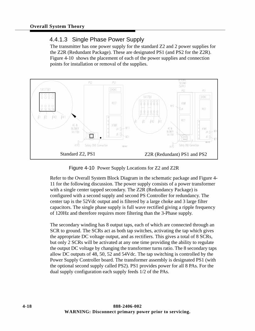
4-
Overall System Theory
4.4.1.3 Single Phase Power SupplyThe transmitter has one power supply for the standard Z2 and 2 power supplies for the Z2R (Redundant Package). These are designated PS1 (and PS2 for the Z2R). Figure 4-10 shows the placement of each of the power supplies and connection points for installation or removal of the supplies.
Figure 4-10 Power Supply Locations for Z2 and Z2R
Refer to the Overall System Block Diagram in the schematic package and Figure 4-11 for the following discussion. The power supply consists of a power transformer with a single center tapped secondary. The Z2R (Redundancy Package) is configured with a second supply and second PS Controller for redundancy. The center tap is the 52Vdc output and is filtered by a large choke and 3 large filter capacitors. The single phase supply is full wave rectified giving a ripple frequency of 120Hz and therefore requires more filtering than the 3-Phase supply.
The secondary winding has 8 output taps, each of which are connected through an SCR to ground. The SCRs act as both tap switches, activating the tap which gives the appropriate DC voltage output, and as rectifiers. This gives a total of 8 SCRs, but only 2 SCRs will be activated at any one time providing the ability to regulate the output DC voltage by changing the transformer turns ratio. The 8 secondary taps allow DC outputs of 48, 50, 52 and 54Vdc. The tap switching is controlled by the Power Supply Controller board. The transformer assembly is designated PS1 (with the optional second supply called PS2). PS1 provides power for all 8 PAs. For the dual supply configuration each supply feeds 1/2 of the PAs.
Standard Z2, PS1 Z2R (Redundant) PS1 and PS2
18 888-2406-002WARNING: Disconnect primary power prior to servicing.
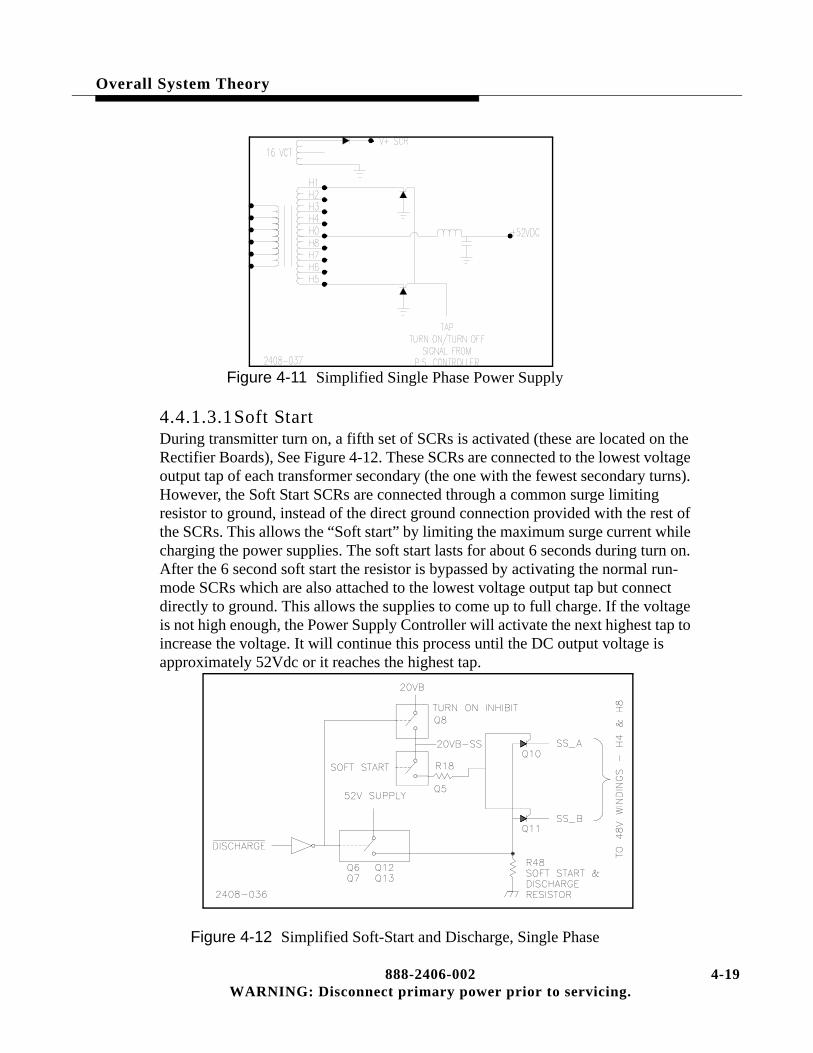
Overall System Theory
Figure 4-11 Simplified Single Phase Power Supply
4.4.1.3.1Soft StartDuring transmitter turn on, a fifth set of SCRs is activated (these are located on the Rectifier Boards), See Figure 4-12. These SCRs are connected to the lowest voltage output tap of each transformer secondary (the one with the fewest secondary turns). However, the Soft Start SCRs are connected through a common surge limiting resistor to ground, instead of the direct ground connection provided with the rest of the SCRs. This allows the “Soft start” by limiting the maximum surge current while charging the power supplies. The soft start lasts for about 6 seconds during turn on. After the 6 second soft start the resistor is bypassed by activating the normal run-mode SCRs which are also attached to the lowest voltage output tap but connect directly to ground. This allows the supplies to come up to full charge. If the voltage is not high enough, the Power Supply Controller will activate the next highest tap to increase the voltage. It will continue this process until the DC output voltage is approximately 52Vdc or it reaches the highest tap.
Figure 4-12 Simplified Soft-Start and Discharge, Single Phase
888-2406-002 4-19WARNING: Disconnect primary power prior to servicing.

4-
Overall System Theory
4.4.1.3.1PA Power Supply DischargeThe PA Power Supply Discharge circuit also uses the Soft Start resistor to discharge the 52Vdc PA supply. The discharge circuit is activated when the transmitter is turned off. When the discharge circuit is active, it disables the SCRs to prevent the supply from trying to turn on during a discharge cycle.
4.4.1.3.216VCT SecondaryThere is a 16VCT secondary on each transformer whose output goes to the Rectifier Board for that supply. It is rectified and used as the drive for the gates of the SCRs. This is required due to the large gate drive current needed on the large single phase SCRs. The rectified voltage from this secondary is called V+SCR on the Rectifier Board. It is also fused on the Rectifier Board.
4.4.2 Low Voltage Power SupplyThe Low Voltage Power Supply is a single PC board mounted in the rear of the transmitter near the main contactor. It is designated A19 (assembly 19). The circuit board is the same for the 3-Phase and single phase configurations, only the wiring to and from the board is changed. It supplies DC voltages to all circuits in the transmitter. These include:
• +20VDC
• -20VDC
• +10VDC
These voltages are sent to the Rectifier boards and then on to the controller boards.
The board contains 3 relays, A19K1, A19K2 and A19K3. When the transmitter is turned on, A19K1 activates the main contactor (simply called K1) which then applies AC to the PA power Supplies, while A19K2 applies AC to the exciter(s). A19K3 selects the low or high fan speed by actuating the fan speed select relay K2 which is mounted near the main AC contactor.
20 888-2406-002WARNING: Disconnect primary power prior to servicing.
Overall System Theory
4.5 Detailed Power Supply Descriptions
4.5.1 3-Phase PA Power SupplyRefer to the Overall System Block Diagram in the schematic package for the following discussion. The transmitter 3 phase AC inputs connect directly to K1, the AC mains contactor. The transformer side of the contactor is connected to A17TB1 on the front of the power supply tray. The output side of A17TB1 connects directly to power transformer T1 primary. T1 primary will be tapped for DELTA (3 wire) or WYE (4 wire) depending on the site AC voltage input and must be tapped for the proper AC input voltage. The tapping chart can be found on the Overall System Block Diagram.
The transformer has 2 WYE configuration secondaries with the center connection being the rectified DC output of 52Vdc. The two secondary outputs are combined via L1 and L2. C1 and C2, 120,000uF filter caps, provide the final filtering.
Each of the transformer secondary taps is connected to a Rectifier Board. The secondaries of T1 use the unique tap switching design to give a small window of coarse regulation (approximately 2Vdc change per tap or 6 volt total) to compensate for 3 phase AC line variations.
4.5.1.1 Rectifier BoardThe Rectifier Board contains the SCRs which are used for the tap switching as well as rectification of the 3 phase AC. Each secondary winding has four taps, see Figure 4-13. Each of these taps have one SCR to ground. The Power Supply Controller can turn on any one of the four SCRs at a given time. If the voltage is not high enough at the DC output, the PS Controller can change the transformer turns ratio by turning on a different SCR and therefore utilizing a different secondary tap. The taps closest to the center will provide the least amount of secondary turns in circuit and will therefore give the lowest DC output voltage. This means that the taps which are furthest from the center will give the highest DC output voltage due to more active turns in the secondary.
There are two rectifier boards mounted on the top of each power transformer. The two boards were originally made as one board which is broken apart for assembly. Therefore, there is an “A” side and a “B” side, both of which are shown on the same schematic. The left side of the schematic is the “B” side and the right side is the “A” side (except on sheet 3 which is “B” side only). There is also only one part number for both boards. The “A” Rectifier Board is for the transformer secondary “A” with the “B” Rectifier Board used with transformer secondary “B”. The Rectifier Boards are operated in parallel and are tied together by a ribbon cable, J3, which is shown in the middle of the schematic connecting the “A” and “B” sides.
888-2406-002 4-21WARNING: Disconnect primary power prior to servicing.

4-
Overall System Theory
Figure 4-13 Simplified 3-Phase Transformer Secondary
22 888-2406-002WARNING: Disconnect primary power prior to servicing.

Overall System Theory
4.5.1.2 Rectifier Board Circuit DescriptionRefer to the Rectifier Board schematic and Figure 4-13 for the following. The Rectifier Boards perform three primary functions:
• Dynamic secondary tap switching using SCRs, to maintain a relatively constant supply voltage and thus maintain constant transmitter power output despite fluc-tuations in the 3 phase AC line voltage. It also allows the controller to optimize transmitter efficiency by selecting the best power supply voltage within its lim-ited range of about 6 volts.
• PA Power Supply Soft-Start.
• PA Power supply Discharge.
4.5.1.2.1Tap Switching Circuit OperationThe control signals for the SCRs are active high and come directly from the PS Controller Board. They enter the “B” Rectifier Board at:
• J4-1 - DRIVER 1 (activates SCRs for 48V tap)
• J4-3 - DRIVER 2 (activates SCRs for 50V tap)
• J4-5 - DRIVER 3 (activates SCRs for 52V tap)
• J4-7 - DRIVER 4 (activates SCRs for 54V tap)
NOTE:The circuit for the 48V tap will be explained here as the other three are identi-cal, but are attached to different transformer taps.
The DRIVE_1 signal is used to activate the 48Vdc tap on both secondaries. When active (HIGH) it causes the output of U2-17 to go low. This turns on Q28 which applies 10VB-SS, now called DRIVE_1, to R12 on the “B” side of the 48V section. Interconnect cable J3 then connects the same signal to R25 on the “A” side Rectifier Board 48V section.
NOTE:The 10VB-SS (SS = Soft Start) will only be present if the DISCHARGE sig-nal at J4-6 is inactive. See PA Power Supply Discharge later in this section for more information.
The 10VB-SS forward biases diodes CR4, CR8 and CR12 on the “B” side and CR13, CR17 and CR21 on the “A” side. This turns on the associated SCRs, Q4, Q8 and Q12 for the “B” side and Q13, Q17 and Q21 on the “A” side. Each of the SCR anodes are tied to ground with the cathode connected through a 30 amp fuse to a tap on one of the transformer secondaries. The “B” side is connected to L5, M5 and N5 with the “A” side connected to L4, M4 and N4 (see the Overall System Block
888-2406-002 4-23WARNING: Disconnect primary power prior to servicing.

4-
Overall System Theory
Diagram for these connections). Note that both the “A” and “B” side SCRs have selected the same relative (lowest voltage) taps on each of the two transformer secondaries.
4.5.1.2.2PA Power Supply Soft-StartSoft-Start is used to limit the surge current during transmitter turn on. The Soft Start and PA Power Supply Discharge circuits are able to use the same resistor, R48 since only one or the other will be active at any one time. A simplified diagram of the Soft Start and PA Power Supply Discharge circuits in shown in Figure 4-9. The Soft-Start control signal is active high and comes directly from the PS Controller Board, via J4-8. A high SOFT START signal at J4-8 causes U2-12 to go low. This turns on FET switch Q32 which then applies the 10VB-SS through R65 to CR28, CR29 and CR30. This in turn activates SCRs Q34, Q35 and Q36. The three SCR outputs are labeled SS1-B, SS2-B and SS3-B and are connected to the 48V taps on the transformer “B” secondary. This allows the power supply to start charging through R48, a 5 ohm 100W current limiting resistor. After about 2 seconds, the DRIVER 1 signal will activate the normal 48V tap SCRs which will tie the taps directly to ground, bypassing R48.
4.5.1.2.3PA Power Supply DischargeThe PA Power Supply Discharge circuit uses R48 to bleed down the supply whenever the transmitter is turned off. The DISCHARGE signal is active low and comes from the PS Controller Board. When low, it causes the output of U2-14 to go high. This does two things:
a. First, it reverse biases CR31 which allows the gate of Q33 to pull high through R54, thus shutting Q33 off. This removes the 10VB-SS used to acti-vate the transformer taps. This prevents the PA Supply (and Soft Start) from being activated while the DISCHARGE signal is active.
b. Second, it allows the base of Q37 to pull high, shutting it off. R62 will then pull the gates of Q29 and Q31 low turning them on. Q29 and Q31 are switches which tie the 52Vdc to R48, and the supply is discharged.
4.5.1.2.4Voltage SamplesTwo AC voltage samples are taken from the 48V taps using 301K ohm resistors. One from the “A” secondary at J4-14 and one from the “B” secondary at J4-13. The samples are pulsating DC with a frequency of 360Hz and an amplitude whose average is equal to the DC power supply output. They are sent to the PS Controller and used to control the tap switching based on the amplitude of the pulses. The signals are also bandpass filtered at 60Hz to detect blown SCR fuses and 120Hz to detect the loss of one AC input phase.
24 888-2406-002WARNING: Disconnect primary power prior to servicing.

Overall System Theory
To determine if a tap has failed (blown fuse), refer to the Diagnostics Display. For Power Supply 1, Press [STATUS, D,A,A,D] This will show you the screen in Figure 4-14.
Figure 4-14 Power Supply Tap Status
4.5.2 Single Phase PA Power SupplyRefer to the Overall System Block Diagram in the schematic package for the following discussion. The transmitter single phase AC inputs connect directly to K1, the AC mains contactor. The transformer side of the contactor is wired in to power transformers T1 via the 1A17TB1 terminal block on the front of the power supply tray. T1 primary must be tapped for the proper AC input voltage. The tapping chart can be found on the Overall System Block Diagram. The transformer has one center tapped secondary with the center tap being the rectified DC output of 52Vdc. The DC output is filtered by L1, C1, and C15. Each of the transformer secondary taps is connected to an SCR which is controlled by ON/OFF signals from the PS Controller board via the Rectifier Board.
The secondary of T1 uses the unique tap switching design to give a small window of coarse regulation (approximately 2Vdc change per tap) to compensate for AC line variations.
4.5.2.1 Rectifier BoardThe SCRs for the single phase supply are required to carry a much larger amount of current than the 3-Phase counterparts and are therefore much larger. They are mounted on large heatsinks on top of the transformers. The SCRs are used for the tap switching as well as rectification of the AC voltage. Each transformer secondary winding has 8 taps. Each of these taps have one SCR to ground. The secondary is full wave rectified, which means that one SCR on each side of the center tap is used for each voltage level. For example CR1 and CR5 will be active at the same time. The other pairs are CR2 and CR6, CR3 and CR7 and CR4 and CR8. The Power Supply Controller can turn on any pair of the SCRs at a given time. If the voltage is not high enough at the DC output, the PS Controller can change the transformer turns ratio by turning on a different SCR pair and therefore utilizing a different secondary tap. The taps closest to the center will provide the least amount of
888-2406-002 4-25WARNING: Disconnect primary power prior to servicing.
4-
Overall System Theory
secondary turns in circuit and will therefore give the lowest DC output voltage. This means that the taps which are furthest from the center will give the highest DC output voltage due to more active turns in the secondary.
4.5.2.2 Rectifier Board Circuit DescriptionRefer to the Rectifier Board schematic for the following. The Rectifier Boards perform three primary functions:
• Dynamic secondary tap switching using SCRs, to maintain a relatively constant supply voltage and thus maintain constant transmitter power output despite fluc-tuations in the AC line voltage. It also allows the controller to optimize transmit-ter efficiency by selecting the best power supply voltage within its limited range of about 6 volts.
• PA Power Supply Soft-Start.
• PA Power supply Discharge.
4.5.2.2.1Tap Switching Circuit OperationThe control signals for the SCRs are active high and come directly from the PS Controller Board. They enter the Rectifier Board at:
• J4-1 - DRIVER 1 (activates SCRs for 48V tap)
• J4-3 - DRIVER 2 (activates SCRs for 50V tap)
• J4-5 - DRIVER 3 (activates SCRs for 52V tap)
• J4-7 - DRIVER 4 (activates SCRs for 54V tap)
NOTE:The circuit for the 48V tap will be explained here as the other three are identi-cal, but are attached to different transformer taps.
The DRIVE_1 signal is used to activate the 48Vdc tap on T1 and T2 secondaries. When active (HIGH) it causes the output of U2-17 to go low. This turns on Q1 which applies 20VB-SS, now called DRIVE_1, to R16.
NOTE:The 20VB-SS (SS = Soft Start) will only be present if the DISCHARGE sig-nal at J4-6 is inactive. See PA Power Supply Discharge later in this section for more information.
The 20VB-SS forward biases diodes CR3, and CR4. This turns on the associated SCRs, CR4 and CR8 on each power supply. Each of the SCR anodes are tied to ground with the cathode connected through a 100 amp fuse to a tap on one of the
26 888-2406-002WARNING: Disconnect primary power prior to servicing.

Overall System Theory
transformer secondaries. Note that both power supplies have selected the same relative (lowest voltage) taps on each of the transformer secondaries.
4.5.2.2.2PA Power Supply Soft-StartSoft-Start is used to limit the surge current during transmitter turn on. The Soft Start and PA Power Supply Discharge circuits are able to use the same resistor, R48 since only one or the other will be active at any one time. A simplified diagram of the Soft Start and PA Power Supply Discharge circuits in shown in Figure 4-12. The Soft-Start control signal is active high and comes directly from the PA Controller Board, via J4-8. A high SOFT START signal at J4-8 causes U2-12 to go low. This turns on FET switch Q5 which then applies the 20VB-SS through R18 to CR28 and CR29. This in turn activates SCRs Q10 and Q11. The SCR outputs are labeled SS_A and SS_B, and are connected to the 48V taps, H4 and H8, on the secondary of T1 and T2. This allows the power supply to start charging through R48, a 5 ohm 100W current limiting resistor. After about 5 seconds, the DRIVER 1 signal will activate the normal 48V tap SCRs, CR4 and CR8, which will tie the taps directly to ground, bypassing R48.
4.5.2.2.3PA Power Supply DischargeThe PA Power Supply Discharge circuit uses R48 to bleed down the supply whenever the transmitter is turned off. The DISCHARGE signal is active low and comes from the PS Controller Board. When low, it causes the output of U2-14 to go high. This does two things:
a. First, it reverse biases CR31 which allows the gate of Q33 to pull high through R54, thus shutting Q8 off. This removes the 20VB-SS used to acti-vate the transformer taps. This prevents the PA Supply (and Soft Start) from being activated while the DISCHARGE signal is active.
b. Second, it allows the base of Q9 to pull high, shutting it off. R62 will then pull the gates of Q6, Q7, Q12 and Q13 low, turning them on. Q6, Q7, Q12 and Q13 are switches which tie the 52Vdc to R48, and the supply is dis-charged.
4.5.2.2.4Voltage SamplesAn AC voltage sample is taken from the 48V taps using 200k ohm resistors. One from SS_A and one from SS_B. The samples are pulsating DC with a frequency of 120Hz and an amplitude whose average is equal to the DC power supply output. They are sent to the PS Controller and used to control the tap switching based on the amplitude of the pulses. The signals are also bandpass filtered at 60Hz to detect blown SCR fuses.
To determine if a tap has failed (blown fuse), refer to the Diagnostics Display, see Figure 4-14 on page 4-25.
888-2406-002 4-27WARNING: Disconnect primary power prior to servicing.

4-
Overall System Theory
4.5.2.2.5Low Voltage Supply RegulatorsU1, U3 and U4 regulate the voltages from the Low Voltage Supply down to 7.1Vdc, +20Vdc and -20Vdc respectively. These voltages are sent to the controller where they will be distributed to the individual controller boards. Input voltages to these regulators will vary depending on the AC mains voltage.
4.5.2.2.616VCT, V+SCR SupplyThe 16VCT secondary winding is fused by F3 and F4 on the Rectifier Board. These are self-resetting fuses which physically look like disc capacitors. The AC is rectified by CR10 and CR11 and becomes V+SCR which is the gate drive signal for the tap and soft start SCRs.
4.5.2.2.7Heat Sink TemperatureThe temperature of the rectifier heatsink is monitored by Thermistor, RT1. A fault is triggered if the temperature of the rectifier heatsink exceeds 100°C and the power supply will be shut off. This temperature can be monitored in the Status Menu of the Diagnostics Display. If the thermistor is shorted, the temperature reading will be about 155°C or higher and the supply shut off. If it is open it will cause a Thermistor Fault to show up in the fault log.
4.5.3 Power Supply ID JumpersThe 3 Phase and Single Phase supplies both have ID jumpers which are set to designate the power supply as PS1 (or PS2 for optional Dual Supply system). This lets the PS Controller know which power supply it is connected to, for proper reporting to the Master Controller. The PS Controller will not allow 2 ID’s to be the same. The jumper configurations are given below. These jumpers are located on the Rectifier Boards on both the 3 Phase and Single Phase supplies.
PS#1 PS#2 PS#3 PS#4
JP1 IN OUT IN OUT
JP2 OUT IN IN OUT
JP3 OUT OUT OUT IN
28 888-2406-002WARNING: Disconnect primary power prior to servicing.

Overall System Theory
4.5.4 Low Voltage Power Supply BoardThe AC input for this board is dependant on the AC voltage and configuration for the transmitter, 3-phase Delta (3 wire), 3-phase WYE (4 wire) or single phase. The same board is used in all three cases. The AC inputs to the board come from circuit breaker, CB1, and enter the board at J1-1 and J1-4. For the 3-phase Delta and Single Phase J1-1 is Phase A and J1-4 is Phase B (Phase C for the 3-Phase does not connect to this board). For the 3-phase 4 wire WYE J1-4 is Phase B and J1-1 is the Neutral.Transformer T1 has dual full wave rectifiers. The T1 secondary outputs are fused by F3, F4, F5 and F6, and are then full wave rectified for two DC outputs of +10Vdc. The +10Vdc is filtered by C1-C6 and connected to the rectifier boards, on top of the PA power supply transformers, in the bottom of the transmitter. Transformer T2 secondaries are fused by F7, F8, F9 and F10 before going to dual bridge rectifiers. The rectifier outputs are filtered by C7-C10 and supply +20Vdc and -20Vdc to the Rectifier Boards on the PA power supply transformers.
All three voltages pass through the rectifier boards and are sent to the Backplane Board to power all of the controller PC boards.
4.5.4.1 RelaysThere are three mechanical relays on the Low Voltage Power Supply Board assembly A19. They are A19K1, A19K2 and A19K3. The relays are powered by +12Vdc from the Life Support Board in the controller.
• A19K1 is activated when the transmitter is turned on and the “CONTACTOR_ON” signal from the Life Support Board goes low. When acti-vated, A19K1 supplies Phase A (or Neutral) to the coil of the AC mains contactor K1 (and K3 in the Auxiliary cabinet for the single phase), which then supplies AC to the PA power supply transformers.
• A19K2 is activated by the same “CONTACTOR_ON” signal and supplies Phase B to the exciter(s). Note that this means the exciter(s) will not have power until the transmitter is turned on.
• A19K3 is activated by the active low “FAN_SPEED_SELECT” signal from the Life Support Board. A19K3 activates the fan speed select relay K2 mounted under the AC mains contactor on the cabinet wall. K2 is shown on the Overall System Block Diagram in the HIGH fan speed position. When A19K3 pulls in so does K2 (not A19K2). K2 simply directs the AC to the high or low speed wind-ings on the motor.
888-2406-002 4-29WARNING: Disconnect primary power prior to servicing.

4-
Overall System Theory
4.6 Cooling System Description
The transmitter is cooled by the single, two speed fan in the lower rear of the transmitter. It uses a high volume, low velocity, air system. Air ducting for inlet air should be well filtered and, if possible, at a slightly positive pressure. The exhaust air ducting should cause very little or no back pressure due to the low velocity air system. Air handling recommendations are shown on the Cabinet Outline Drawings in the schematic package.
Upon transmitter turn on, the fan will run at high speed for one minute, then will normally run at the low speed until a fault occurs or there is a significant increase in temperature detected by the controller. The blower motor is a 2 speed, single phase motor. The fan speed can also be manually set to HIGH speed or AUTO in the Configuration Menus of the Diagnostics Display.
4.7 Control System Description
The control system is a micro-controller based master/slave system. It monitors over 100 operating functions in the transmitter and can make intelligent operating decisions based on operating conditions. It has the standard parallel remote connections. The microprocessor control system allows fast and efficient monitoring of the entire transmitter offering a level of protection and diagnostics not available with a simple logic controller. It also makes changes and upgrades a simple matter of changing the firmware.
The Controller consists of the following boards:
• Master Controller Board
• PA Controller
• PA Controller #2 (Optional)
• Power Supply Controller
• Power Supply Controller #2 (Optional)
• Life Support Board
• Display/Backplane Board (motherboard)
All of these boards are located directly behind the transmitter control panel and plug into the Display/Backplane Board. The entire assembly is considered the “System Controller”.
30 888-2406-002WARNING: Disconnect primary power prior to servicing.

Overall System Theory
The Controller functions include:
• Transmitter Control Functions
• Automatic Power Control, or APC
• VSWR Monitoring and Overload Protection
• Power Supply Monitoring and Protection
• Power Amplifier Monitoring and Protection
• Automatic power foldback for VSWR, Over-temperature and Over-current con-ditions.
• AC Restart
• System Calibration and Configuration
• Detailed Status, Metering, Configuration and Fault Diagnostics display screens.
4.7.1 Master ControllerThe Master Controller is responsible for primary transmitter control and is the summary point for all of the information gathering. It controls and/or receives information from the PA Controllers, Power Supply Controllers and Life Support Board and takes action appropriate to the operating conditions of the transmitter. It is also responsible for the transmitter power control, system configuration, calibration, VSWR protection and the Transmitter and Diagnostics displays on the front panel.
However, the rest of the control system is designed to operate with the Master Controller removed from the system in what is called Life Support Mode. The PA and PS Controllers report to the Master Controller but operate independently to allow them to continue operating even if the Master is removed. In the event of a Master Controller failure the Life Support Board disconnects all Master Controller control functions from the transmitter and initiates minimal protection and control to keep the transmitter on the air. For more information on Life Support Mode, refer to the Life Support Board description later in this section.
4.7.1.1 EEPROM U39The Master Controller has 3 memories, ROM (firmware), RAM (volatile) and an EEPROM (non-volatile) U39. When the low voltage is applied to the controller it loads up the program from ROM to RAM and then goes to the EEPROM for all of the transmitter configuration, calibration settings, power levels, fault limits etc.. Basically EEPROM U39 stores any settings that can be changed in the Diagnostics Display. Any changes made in the Diagnostics Display will be either automatically saved in the EEPROM or is saved when the [BACK] button is pressed (ie. Back to Update).
888-2406-002 4-31WARNING: Disconnect primary power prior to servicing.

4-
Overall System Theory
All the individual bits or bytes of information stored here have a default setting which is stored in the firmware ROM. When the information in U39 is uploaded to RAM it is checked against the default values. If it is considered to be out of tolerance (or invalid data) it will automatically be replaced with the default value from the ROM. When this happens the fault “EEPROM_DEF” (Default) will be placed in the fault log. The only time this should happen is when a new EEPROM, U39 is installed in the Master Controller. Since it is basically blank, all of the default settings from the ROM will be written to U39 one at a time as it finds they are out of tolerance. After this has happened, the EEPROM_DEF fault should never happen again. If it does, U39 should be replaced since a memory location is probably bad. For information on replacing EEPROM U39 see Section V, Maintenance and Alignments.
The following is a listing of all of the Default Values which are stored in the Firmware:
• Forward Factor - 0.003079
• Reflect Factor - 0.000123
• Cal APC Factor - 3.03
• Cal Frequency - 98MHz
• Operating Frequency - 98MHz
• IPA Factor - 200
• Exciter Factor - 200
• TPO 100% - 02.00kW
• Max High - 03.00kW
• Max Low - 01.00kW
• UPS Setting - 01.00kW
• Low Power Alarm - 01.80kW
• VSWR Foldback - 1.35
• VSWR Fault - 1.5
4.7.1.2 APC, Automatic Power ControlOne important function of the Master Controller is transmitter power control, which is accomplished via the APC Loop. The APC Loop controls the transmitter power and keeps it constant by varying the IPA RF output indirectly proportionate with the forward power. In other words, if the forward power output goes up, the IPA output will be reduced, which will in turn reduce the PA RF output. If the forward power output goes down, the IPA RF output will be increased, which will increase the PA RF output to compensate.
32 888-2406-002WARNING: Disconnect primary power prior to servicing.

Overall System Theory
The APC loop starts at the forward power directional coupler. The forward sample is connected to the Life Support Board where it is calibrated with R127 for 8.9V@ 100% TPO at TP9. This voltage sample is then sent to the Master Controller (schematic sheet 7) where it is squared by multiplier chip U1 (to make the voltage from the coupler proportional to power) and divided by 10. This is then sent to U5-6 where it is compared to APC_REF voltage (APC Reference).
APC_REF is the DC output of a D/A Converter or DAC whose input is called DAC_APC_REF and is controlled by the RAISE and LOWER buttons on the front of the controller (or by the remote control inputs) or can be varied automatically by the Master Controller’s foldback routines. Pressing RAISE increases the APC_REF voltage and pressing LOWER decreases it. The DAC_APC_REF is responsible for all transmitter power control functions including power level, foldbacks and mute. This makes it a very important number to know and understand for troubleshooting.
NOTE:As calibrated from the factory, the digital DAC_APC_REF number should be approximately 660 (this number should be on the factory test data sheet). This number can be checked by pressing [HOME, MORE, CONFIGURATION C,B]. The DAC_APC_REF output voltage APC_REF can be metered at TP8 or in the Diagnostics Display by pressing [METERING, B,B].
The output at U5-7 is the difference between the forward power sample and the APC_REF voltage. This difference can be measured at TP3 on the Master Controller and is called the APC voltage. R13 and R102 divide this voltage down for display on the Transmitter LCD Display on the right side of the controller. The APC voltage is not the same as the APC_REF voltage. The dipswitch, S1-10, is present to allow the APC loop to be opened for troubleshooting. This APC voltage is now sent back to the Life Support Board (Schematic, sheet [3,B8]) and is called MSTR_IPA_CTL (Master IPA Control).
If the Master Controller is operational, then the MSTR_IPA_CTL signal will pass through to U5-4 which will in turn pass the signal if there are no System Mutes present. Due to the low impedance of the circuit, the Manual PWR REF pot R25 has little or no effect on the circuit. CR4 and R30 shift the positive APC voltage to a proportional negative voltage which is passed on to IPA_AB1 or AB2 depending on the position of K2. Remember that the gate bias on the RF amplifiers is -18V for OFF and -0.6V for fully ON.
Since the exciter power is fixed, changing the IPA bias will increase or decrease the IPA output which will then proportionately increase or decrease the output of the PAs.
888-2406-002 4-33WARNING: Disconnect primary power prior to servicing.

4-
Overall System Theory
Example 3 The following is an example of how the entire loop would work. For our example the power output of the transmitter goes down due to a failed PA. This would decrease the output of the forward power directional coupler and the voltage at the input to the difference amp at U5-6 on the Master Controller Board. Since U5 has almost infinite gain, the loop will try to force the forward power sample input to U5 to be the same as the APC_REF input. This will increase the APC voltage at TP3 and on the front panel APC reading. The increased APC voltage will pass through the U5 analog switches (on the Life Support Board) bringing the input to U15-3 less negative. This less negative voltage is sent to the IPA, increasing its output. More drive to the PA will increase the transmitter RF output to compensate for the failed PA.
If the RF power output were to increase, the APC loop voltage would be reduced, lowering the IPA and PA output.
4.7.1.2.1Manual Power ControlIt is possible to shut off the APC by opening dip-switch S1-10 (Open = OFF) on the Master Controller Board. This switch opens the APC Loop, disconnecting the APC voltage from the IPAs. When S1-10 is opened, MANUAL PWR REF R25 on the Life Support board controls the transmitter power output. R25 also serves as the power control for Life Support Mode which means the Master Controller Board has failed. If the Master Controller fails, U5 pins 1-2 are opened, removing the APC voltage from the IPAs, breaking the APC loop. In Life Support Mode, R25 is set to operate the transmitter at 25% of rated power. Proper setting of R25 requires an external wattmeter and is covered in Section V, Maintenance under “Setting Life Support Power Level.”
! CAUTION: IN LIFE SUPPORT MODE THERE IS LIMITED OVERLOAD PROTECTION AND NO FOLDBACK FUNCTIONS. ADJUSTING R25 TO MORE THAN 25% RATED POWER WILL CAUSE THE TRANSMITTER TO SHUT OFF AND COULD DAMAGE THE TRANSMITTER. REFER TO SETTING LIFE SUPPORT POWER LEVEL IN SECTION V, MAINTENANCE.
4.7.2 Calibration Factors and A/D ValuesThe configuration menus in the Diagnostics Display contain the calibration factors and A/D values used by the transmitter for calibration, operation and protection. The cal factors are calculated by the micro when the transmitter is calibrated. The A/D readings are the decimal equivalents of the forward and reflected power sample voltages. The following is a listing of their nominal values:
34 888-2406-002WARNING: Disconnect primary power prior to servicing.

Overall System Theory
Calibration Factors:
• Forward Factor - 0.003079
• Reflect Factor - 0.000123
• APC_Factor - 3.03
• EXC_Factor - See Factory Test Data (Frequency dependent)
• IPA_Factor - See Factory Test Data (Frequency dependent)
A/D Readings
• DAC_APC_REF - 660 (nominal)
• A/D_FWD_PWR - 806 (nominal @ 2kW))
• A/D_RFL_PWR - 700 (nominal @ 60W reflected)
These cal factors and A/D values will be approximately the same for all Z2 transmitters that are factory calibrated or have been field calibrated at the rated transmitter power of 2kW as detailed in the Maintenance procedures. These numbers are also stored in the Backup memory area of the EEPROM, U39 and can be recalled if necessary. The actual numbers obtained during the factory calibration are recorded in the Factory Test Data.
NOTE:If the transmitter is calibrated at other than 2kW these numbers will change and their new values should be recorded.
It is important to note that as long as the hardware calibration of the forward and reflected directional couplers is not disturbed, the Cal Factors could be entered manually and the transmitter calibration would be within a few percent of the factory calibration. To access the edit controls for each parameter, go to the screen containing the value and press and hold the [D] and press [C]. The edit controls should now show up on the screen.
! CAUTION:ENTERING A WRONG VALUE IN ONE OF THESE SCREENS COULD CAUSE SERIOUS DAMAGE TO THE TRANSMITTER OR EXTERNAL SYSTEMS. IT IS RECOMMENDED THAT THESE NUMBERS BE RECALLED FROM THE BACKUP MEMORY OR BE OBTAINED BY FOLLOWING THE CALIBRATION PROCEDURES AS OUTLINED IN SECTION V, MAINTENANCE.
888-2406-002 4-35WARNING: Disconnect primary power prior to servicing.

4-
Overall System Theory
The following is a description of each of these parameters.
4.7.2.1 DAC_APC_REFDAC_APC_REF [HOME, MORE, CONFIGURATION C,B] is a counter (internal to the micro), whose output will be between 0 and 900, that is controlled by the RAISE and LOWER buttons on the front panel. RAISE increases the count and LOWER decreases the count. This number is then D/A converted to get the APC_REF voltage which controls the APC loop discussed earlier in this section. The correct APC_REF voltage for a specific DAC_APC_REF number can be calculated from the formula:
APC_REF voltage = DAC_APC_REF * 0.004883
Example: For the nominal DAC_APC_REF value of 660, APC_REF Voltage = 660 * 0.004883 = 3.22V and can be measured at TP8 on the Master Controller.
This DAC value is used to control transmitter power level for all conditions where the Master Controller is operational and the APC Loop switch S1-10 is closed.
4.7.2.2 Forward Factor and A/D_FWD_PWRThe Forward Factor is a calibration factor that is calculated during forward power calibration. To check the Forward Factor press [HOME, MORE, CONFIGURATION C,A,A]. All Z2 transmitters are factory calibrated with a forward sample voltage of 8.9vdc at 2kW, as measured at TP9 on the Life Support Board. This sample voltage is low pass filtered on the Master Controller and then A/D converted in the micro for metering. This A/D value shows up as A/D_FWD_PWR [HOME, MORE, CONFIGURATION C,B], which at 8.9V should be very close to 806 (the A/D converter is 10 bit for 0 to 1024 range, but the input to the A/D is not actually 8.9V). By setting the FWD PWR CAL screen to 2kW and calibrating we are telling the micro that 806 represents 2kW. The micro now calculates the Forward Factor by dividing the 2kW by the square of 806 or
Forward Factor = FWD PWR CAL (kW) / A/D_FWD_PWR2
Forward Factor = 2kW / 8062 = 0.003079
The A/D FWD PWR reading must be squared to make the voltage from the coupler linearly track the transmitter power output (Power is the square of the voltage).
36 888-2406-002WARNING: Disconnect primary power prior to servicing.

Overall System Theory
The Forward Factor is now used for all forward power level settings. For example, to set the Low power control to 1kW you press the lower button. This gradually lowers the transmitter power output by reducing the DAC_APC_REF and therefore the APC_REF voltage and transmitter power. This in turn lowers forward power sample and the A/D_FWD_PWR number which can be calculated at 1kW as:
A/D FWD PWR = SQRT(FWD PWR / Forward Factor)
A/D FWD PWR = SQRT(1kW / 0.003079) = 570
At an A/D FWD PWR reading of 570 the front panel Forward Power meter will read 1kW.
4.7.2.3 APC FactorAPC_Factor is also calculated during the Forward power calibration. APC_Factor allows the micro to calculate the necessary DAC_APC_REF number to obtain any specific power level. For the Z2, APC_Factor is calculated as Forward calibration power divided by the DAC_APC_REF number or:
APC_Factor = FWD PWR (kW) / DAC_APC_REF
APC_Factor = 2kW / 660 = 3.03
Once the APC_Factor is known, the controller uses this number to calculate the DAC_APC_REF necessary to obtain the MAX HIGH, MAX LOW and UPS power levels in the Diagnostics Display.
4.7.2.3.1Operating APC versus Calibrated APCThere are actually 2 APC_Factors due to the fact that the directional coupler outputs are not flat across the entire FM band. They are:
[HOME, MORE, CONFIGURATION C,A,D,C]
• CAL_APC_Factor (Calibrated APC_Factor)
• OP_APC_Factor (Operating APC_Factor)
The Operating APC Factor is frequency compensated based on the slope of the coupler output and is the factor calculated above. If the transmitter is operating at the same frequency at which it was calibrated then the two numbers will be the same. If the operating frequency is changed, the OP_APC_Factor will be higher or lower depending on whether the frequency went down or up compared to the calibrate frequency. This means that if the exciter frequency is changed the transmitter calibration can be maintained by simply changing the OPERATING_FREQUENCY in the Diagnostics Display.
888-2406-002 4-37WARNING: Disconnect primary power prior to servicing.

4-
Overall System Theory
4.7.2.4 MAX HIGH, MAX LOW and UPS Power LevelsMAX HIGH, MAX LOW and UPS power levels are set using the Diagnostics Display and stored in the EEPROM, U39.
MAX HIGH SET screen [HOME, MORE, CONFIGURATION B,B] sets the maximum power level when the HIGH ON button is pressed.
MAX LOW SET screen [HOME, MORE, CONFIGURATION B,C] sets the Maximum power level when the LOW ON button is pressed.
UPS SET Screen [HOME, MORE, CONFIGURATION B,D,A] sets the power level when the transmitter is operating on a backup UPS or generator AC supply.
Once the operator has set a power level in kW in these screens, the controller uses the OP_APC_Factor to find the DAC_APC_REF that would represent each of the power levels and sets that number as the power level limit. This maximum DAC_APC_REF setting is called DAC_MAX and is calculated for each mode from the formulas below:
For HIGH ON mode:
DAC_MAX = MAX HIGH SET (kW) / APC_Factor
For LOW ON mode:
DAC_MAX = MAX LOW SET (kW) / APC_Factor
For UPS mode:
DAC_MAX = UPS SET (kW) / APC_Factor
DAC_MAX [HOME, MORE, CONFIGURATION C,B] is the display variable which will contain one of the above numbers depending on which mode the transmitter is in. Once these are set, the DAC_APC_REF in that mode can never go above the DAC_MAX setting.
Example: If the transmitter is calibrated at 2kW (HIGH ON), and the desired MAX Power setting is 2.4kW, this would be entered into the MAX HI SET screen. Remember that for 2kW the nominal DAC_APC_REF is 660. The micro would now use the formula:
DAC_MAX_HIGH = MAX HIGH SET (kW) / APC_Factor
DAC_MAX_HIGH = 2.4kW / 3.03 = 792
38 888-2406-002WARNING: Disconnect primary power prior to servicing.

Overall System Theory
This is now the highest possible number for the DAC_APC_REF and will limit the transmitter power to 2.4kW.To prove that:
FWD PWR = APC Factor * DAC_APC_REF
FWD PWR = 3.03 * 792 = 2.4kW
4.7.2.5 EXC Factor and IPA FactorWhen the transmitter Forward Power is calibrated, the micro samples the exciter and IPA outputs and sends the A/D readings to the screen as:
• EXC_Factor [HOME, MORE, CONFIGURATION C,A,D,A]
• IPA_Factor [HOME, MORE, CONFIGURATION C,A,C]
The calibration merely takes the A/D reading for each of these and makes it equal to 100% in the Diagnostics metering of exciter and IPA power output. Since Drive Level changes with frequency, so will these cal factors. The factory cal numbers are in the factory test data sheet.
4.7.2.6 Reflect Factor and A/D_RFL_PWRReflect Factor is a calibration factor that is calculated during reflected power calibration. To check the Reflect Factor press [HOME, MORE, CONFIGURATION C,A,B]. All Z2 transmitters are factory calibrated by reversing the reflected coupler (it now measures forward power) and adjusting for a reflected sample voltage of 2.1V at 60W, as measured at TP18 on the Life Support Board. This sample voltage is low pass filtered on the Master Controller and then A/D converted in the micro for metering. This A/D value shows up as A/D_RFL_PWR [HOME, MORE, CONFIGURATION C,B], which at 2.1V should be very close to 700 (the A/D converter is 10 bit for 0 to 1024 range, but the input to the A/D is not actually 2.1V). By setting the RFL PWR CAL screen to 60W and calibrating we are telling the micro that 700 represents 60W. The micro now calculates the Reflect Factor by dividing the 60W by the square of 700 or
Reflect Factor = RFL PWR CAL (kW) / A/D_RFL_PWR2
Reflect Factor = 60W / 7002 = 0.000123
The A/D_RFL_PWR reading must be squared to make the voltage from the coupler linearly track the transmitter power output (Power is the square of the voltage).
The actual VSWR fault level in the transmitter is set at 1.5:1 (which is 80W). The Foldback level is set at 1.35:1 (which is 44W). The Reflect Factor can now be used to set the fault and foldback levels by calculating the A/D_RFL_PWR number that would represent a specific power level using the formula:
888-2406-002 4-39WARNING: Disconnect primary power prior to servicing.
4-
Overall System Theory
A/D_RFL_PWR = SQRT(RFL_PWR / Reflect Factor)
A/D_RFL_PWR = SQRT(80W / 0.000123) = 806 (Fault) or
A/D_RFL_PWR = SQRT(44W / 0.000123) = 598 (Foldback)
VSWR protection is based on this A/D reading, which is directly proportional to a reflected power level, not on a calculated VSWR reading.
4.7.3 VSWR FoldbackThe Master Controller contains another DAC called VSWR_FB_LVL which stands for VSWR Foldback Level. The output of this DAC is directly controlled by the setting in the VSWR Foldback Screen [HOME, MORE, CONFIGURATION B,D]. The normal setting for this screen is 1.35. Using the formula below, this is equal to 44W for 2kW forward power.
RFL PWR = (VSWR-1 / VSWR+1)2 * 2kW
RFL PWR = (1.35-1 / 1.35+1)2 * 2kW = 44W
Now using a formula from the previous section:
A/D_RFL_PWR = SQRT(44W / Reflect Factor) = 598
This says that when the output voltage from the reflected coupler is sufficient to increase the A/D_RFL_PWR reading to 602, the reflected power is 44W. Therefore, the VSWR_FB_LVL DAC is set to 602 and its dc output voltage will be about 1.8V. This voltage is sent to U7-12 as one input to the open loop gain differential amplifer. U7-13 is the calibrated voltage from the reflected coupler (from Life Support Board). As long as there is little or no reflected power the voltage at U7-13 will be zero and the U7-14 output will be at the positive rail. This reverse biases diode CR1 which is connected to the APC Voltage at U5-10. If the voltage from the coupler exceeds the VSWR_FB_LVL, U7-14 will try to go to the negative rail (GND). This will forward bias CR1 and the APC voltage will be pulled to ground through CR1 and R5. This in turn will reduce the reflected coupler output and the clamp will be removed from the APC Voltage and the power will try to come back to normal. Since this is happening extremely fast, once the reflected coupler output voltage exceeds the VSWR_FB_LVL, the new APC loop will try to keep the 2 inputs to U7 the same, preventing the reflected power from exceeding 44W. Basically, a new APC loop (using the output from the reflected coupler instead of the forward) has been formed which takes precedence over the forward power loop.
40 888-2406-002WARNING: Disconnect primary power prior to servicing.

Overall System Theory
4.7.3.1 Master Controller FaultsFor a complete listing of all of the faults associated with the Master Controller refer to Section VI, Troubleshooting.
4.7.3.1.13 Strike RoutineThere are 2 faults in the transmitter that will initiate what is called a 3 strike routine. They are:
• RFL_PWR - VSWR greater than 1.5:1
• ISO_BZ - The predicted temperature of R9 on the “B” Z-Plane Isolation board is greater than 130oC.
Strike 1 - When any of the above fault conditions is met, the transmitter output is muted (DAC_APC_REF is brought to zero) for 3 seconds (6 seconds for transmitters with a Single Phase power supply). At the end of the 3 (or 6) seconds the transmitter power is slowly ramped back up and a 10 second timer is started.
Strike 2 - If another fault is detected before the 10 seconds is up, the transmitter will again mute for 3 (or 6) seconds, start the 10 second timer again and slowly ramp the power up again.
Strike 3 - A third fault detected within this 10 seconds will cause the transmitter to be muted until the operator gives the transmitter an ON command (High or Low), locally or by remote. If the cause of the fault is still present, the transmitter will simply repeat the 3 strikes and mute again.
NOTE:If no faults occur during either of the 10 second time periods, then the strike counter is reset and will allow 3 more strikes before muting the transmitter.
The slow ramp up in power after a strike should allow the foldback controls to limit the transmitter power output before the fault thresholds are reached again. The slow power ramps are designed to allow the transmitter to operate at the maximum possible power level without over-dissipating the isolation resistors or exposing the transmitter to excessive reflected power. This would mean that there would be a fault in the log but it would be inactive and the transmitter would be in a foldback condition.
888-2406-002 4-41WARNING: Disconnect primary power prior to servicing.

4-
Overall System Theory
4.7.4 PA Controller BoardThe PA Controller Board utilizes a micro-controller which reports to the Master Controller, but operates independently of the Master. The board ID is set via DIP switches to make it PA Controller #1. The Backplane Board has slots for up to 4 PA Controllers which are used for the higher power Z Series transmitters such as the Z5 and Z10. Each PA Controller can handle 8 PAs and therefore only one is needed in the Z2, except in the Z2R which uses 2 PA Controllers for increased redundancy (see Table 4-1 on page 4-59).
The PA Controllers are responsible for the following:
• Turn on/Turn off of the PAs via the PA gate bias voltage.
• Metering, status and fault monitoring of the PAs and the isolation resistors associ-ated with them.
• Control of the combiner isolation switches (located on the isolation boards) which are associated with the PAs under its control.
• Crossover protection - the ability to mute the PAs which are controlled by the other PA Controller Board in case of a failure (only available in the Z2R)
4.7.4.1 PA Turn On/Turn OffThe PA Controller’s primary responsibility is to turn the PAs on and off. The PAs are turned on and off by varying the bias voltage on the gates of the MOSFETs on the PAs. If the gate voltage is -0.6V, the PA is turned on full. If the gate voltage is -18V, then the PA is turned off. This means the PA Controllers have the ability to turn off or MUTE each PA individually, or all at the same time if it is necessary to MUTE the entire transmitter RF output.
Whenever a defective PA is to be shut off or MUTED, all of the PAs will be MUTED for 120mS while the defective PA is disconnected from the combiner by the isolation switch. The rest of the PAs are then turned back on.
4.7.4.1.1Control Distribution and Controller Failure (Z2R Only)Each PA Controller controls half (4) of the PAs, see Table 4-1 on page 4-59. Note that each PA Controller Board controls two PAs on each foursome. This pattern of control distribution allows for maximizing of power output if one of the PA Controller Boards fails.
4.7.4.2 MeteringThe PA Controllers are responsible for metering of the following parameters:
42 888-2406-002WARNING: Disconnect primary power prior to servicing.

Overall System Theory
• PA Current - The current draw of each PA is monitored by measuring the voltage drop across 0.01 ohm resistors, R11-R18, on the Z-Planes. The resistors show up as part of the Divider Schematic. This allows the current of each individual PA to be available on the Diagnostics Display. To check the PA currents press [METERING A,B,C].
• PA Supply Voltage - The Voltage of PS1 is monitored with fused samples also from the Z-Plane Divider. To check the PA supply voltage press [METERING B,C].
• PA Gate Voltage - Each individual PA gate voltage can be checked on the Diag-nostics Display by pressing [METERING B,D].
• PA Temperature - There is a temperature sensor on each PA which sends a tem-perature sample voltage to the PA Controller.
• PA ISO Resistor Temperatures - VTEMP PA1 through VTEMP PA8 -Each ISO resistor has a thermistor, used as a temperature sensor, attached to it for metering and fault monitoring. To check the ISO resistor temperatures press [METERING C,C then D to see B5-B8]. A rise in the ISO resistor temperature indicates an imbalance in the phase or amplitude of a PA output.
NOTE:The temperature of the different PA ISO resistors (A1-A8) can vary quite a bit, but are considered okay if they are under Ambient + 75°C.
AZ, which also shows up in this screen, is the temperature indication for the 2.5kW, 2 way combiner isolation load resistor. A rise in this temperature would indicate an imbalance between the outputs of the two foursomes on the Z Plane.
4.7.4.3 Crossover (XOVER) Protection (Z2R only)Each PA Controller has what is called a Watchdog Timer. The outputs of the watchdog timers are each monitored by the other PA Controller. If the pulses from the watchdog timer are interrupted, due to either hardware or software problem, the other PA Controller will initiate what is called a Crossover (or XOVER). Basically, the operational PA Controller will apply a mute to all of the PAs associated with the defective PA Controller, and switch them out of circuit before releasing the mute on its own PAs. Maximum power output with one PA Controller out is approximately 33% of nominal.
NOTE:The Power Supplies, PS1 and PS2, each power the PAs associated with the same number PA Controller. This means that the loss of one power supply will create the same scenario as loss of one PA Controller (the loss of 2 PA per foursome).
888-2406-002 4-43WARNING: Disconnect primary power prior to servicing.
4-
Overall System Theory
4.7.4.4 PA Controller FaultsFor a complete listing of the faults associated with the PA Controllers refer to Section VI, Troubleshooting.
4.7.5 Power Supply ControllerThere is only one PS Controller Board and one power supply in the standard Z2 transmitter. The Z2R has 2 power supplies and 2 PS Controllers. Each controller is capable of controlling up to 2 power supplies completely independent one from another. This allows one of the supplies to have a critical failure and be shut off without interrupting the operation of the second supply.
The PS Controller functions include the following:
• Control of the tap switching which is used to coarsely regulate the power supply voltage to 52Vdc.
• Control of the Soft-Start and PA Power Supply Discharge functions.
• All power supply monitoring and fault detection. These include voltage, current, temperature and status.
4.7.5.1 Power Supply Turn OnThe primary function of the PS Controller is to turn the power supply on and off. The on/off signal is called PS_DISABLE and comes in on J3-13. The signal originates on the Master Controller but passes through a logic gate on the Life Support Board before reaching the PS Controller. PS_DISABLE is an active high signal which means that if the signal is high the power supply will be shut off (the secondaries will be deactivated by shutting of the SCRs but primary voltage could still be present). If it is low, the power supplies will be activated, unless there is a critical fault on the PS Controller board, in which case the supplies will be shut off regardless of the PS_DISABLE signal. The power supplies are turned on via one of the four outputs:
• DRIVER 1 (TAP 1 - 48V)
• DRIVER 2 (TAP 2 - 50V)
• DRIVER 3 (TAP 3 - 52V)
• DRIVER 4 (TAP 4 - 54V)
These outputs are duplicated, one set for PS1 and the other for PS2. When the transmitter is turned on the Master Controller brings the PS_DISABLE signal low (provided the contactor has been activated and the Master Controller is operating normally). This will first activate the SOFT_START outputs at J1-8 and J2-8. This allows the supplies to charge slowly, limiting the in-rush current via the soft-start resistor and SCRs on the rectifier boards. The supply voltage must reach at least 40Vdc within 3 seconds, (6 seconds for a single phase supply) otherwise the turn on
44 888-2406-002WARNING: Disconnect primary power prior to servicing.

Overall System Theory
sequence will be aborted. After 3 (or 6) seconds, if the voltage is within tolerance, the PS Controller will activate the lowest available voltage tap by activating one of the four DRIVER signals. Since DRIVER_1 is connected to the 48V tap, it will be activated first (if available) and the power supplies will come up to full charge.
The PS Controller will now check the power supply voltages via the DC Voltage Samples from each power supply. These come into the board at J1 and J2, pins 13 and 14 from the rectifier boards. These signals pass through U7 which acts as a linear amplifier and buffer to prevent the analog samples from overloading the front end of the A/D converter in the microcontroller IC, U6. Using these samples the PS Controller will determine when and if it is necessary to change taps to increase or decrease the DC PA voltage. It will try to maintain the voltage as close as possible to 52Vdc.
4.7.5.2 PA Power Supply DischargeWhen the PS_DISABLE signal goes high, all of the SCR taps are disabled and the DISCHARGE signals at J1-7 and J2-7 go low. This activates the PA Power Supply Discharge circuit, which allows a quick and safe discharge of the PA supply.
4.7.5.3 Power Supply Standby ModeUnder certain circumstances, such as RF Mute, the power supplies will be placed in standby mode via the signal PS_STANDBY. This signal comes from the Master and PA Controllers. PS_STANDBY shuts off all the DRIVER signals which deactivates all of the SCR taps on the power supply. However, it does not activate the discharge circuit. This allows the filter capacitors to maintain charge and be ready to supply power at a moments notice without having to go through the Soft-Start sequence again. However, the capacitors will bleed down slowly if the standby mode is maintained. To keep the voltage within reasonable limits, the PS Controller will activate the Soft-Start circuit if the PA voltage drops below 42Vdc and shuts it off when the voltage is above 52Vdc. The PS Controller will maintain charge in this manner until the PS_STANDBY signal goes low, and the power supply is fully active again or shut off by the PS_DISABLE signal.
4.7.5.4 Discharge Protection CircuitThe discharge protection circuit protects the power supply and the discharge circuit components from a failure in the discharge circuit. Specifically it protects against a short which would cause the discharge resistor to be “In circuit” when the power supply is activated.
888-2406-002 4-45WARNING: Disconnect primary power prior to servicing.

4-
Overall System Theory
A sample of the voltage across the discharge resistor is sent to the PS Controller at J1-20 and J2-20. If the voltage is more than 30Vdc, the comparator will trip, and the output at U1-1 or U1-2 will go LOW. The fault signal 1_DISCH_SAMPLE is then sent to U9-2 where it is buffered before reaching the micro-controller. The PS Controller would then shut down the power supply. The detection circuit contains hysterisis to prevent false triggering.
4.7.5.5 RESETThere is a RESET line from the Life Support Board which is monitoring the +20Vdc from the regulators on the Rectifier Boards. This is basically monitoring the Low Voltage Power Supply. If the voltage falls below a set threshold, U37 on the Life Support Board generates the RESET (active low) which is sent to all of the controller boards (Master, PAC and PSC). On the PS Controller this RESET clears U2 and U3, which brings their outputs low. This deactivates all of the DRIVER signals, disconnecting all of the SCR taps and shutting off the supply. This also activates the DISCHARGE(BAR) signal which then bleeds off the supply.
4.7.5.6 Watchdog TimerThe watchdog timer, U4 is basically looking for two things. First, it must receive a pulse from the micro-controller every 1.0mSec. If it does not it will activate the RESET line at TP4, and the supply will be shut off. It is also monitoring the +20Vdc supply. If the voltage falls below the minimum limit of 12V, it will activate the RESET line.
4.7.5.7 Analog InputsU7 acts as a linear amplifier and buffer for the analog inputs to the A/D converter which is part of U6.
• SAMPLE 1 and SAMPLE 2 are the voltage samples from the power supply. Pri-marily it is used to control the power supply tap switching. However they are also digitally filtered by the micro-controller by two filters. The first is a 50/60 HZ band pass filter whose output is used to detect a loss of a rectifier fuse on the transformer secondary, a non-critical fault. The second is a 100/120 Hz band pass filter which is used to detect a severe primary phase imbalance or loss of phase. Loss of phase is a critical fault which will shut the power supply off momentarily (see “Power Supply Controller Faults” in Section 6 of this manual).
• HEAT SINK THER(mistor) is the temperature sensor located on the rectifier heatsink. If the heat sink temperature exceeds 100°C it will shut the power supply off.
NOTE:There are test points located after U7 which give a place to check the analog voltages actually going into the A/D converter.
46 888-2406-002WARNING: Disconnect primary power prior to servicing.

Overall System Theory
4.7.5.8 PS Controller FaultsFor a complete listing of all of the faults associated with the PS Controller refer to Section VI, Troubleshooting.
4.7.6 Life Support BoardThe Master Controller is backed up by the Life Support Board. The Life Support Board allows safe transmitter operation at reduced power if the Master Controller is not operating. The transmitter does require the PA and PS Controller(s) to be operational. The basic controller functions available in Life Support Mode are:
The Life Support Board has two basic modes of operation:
1. Normal Operational Mode. The Life Support Board basically acts as an interface between the Master Controller and various parts in the transmitter when the Master Controller is functioning properly. 2. Life Support Mode. This mode provides a minimal backup control system should the Master Controller fail. If the Master Controller board fails, the Life Support Board disconnects (via AND gates) all signals from the Master Controller and allows the transmitter to stay on the air at 1/4 power with minimal fault protection and no visible monitoring for the operator.
Transmitter functions available in Life Support Mode:
a. VSWR Protection
b. System Mute
c. Transmitter ON (LOW only) and OFF (both LOCAL and REMOTE inputs are active)
d. Failsafe Interlock
e. External Interlock
4.7.6.1 Normal Operational ModeThe following contains all pertinent circuit operation when the Master Controller is functioning properly.
4.7.6.1.1Transmitter Turn OnWhen the transmitter is turned on, either HIGH or LOW, the Master Controller generates a high TX_ON signal which enters the Life Support Board at J1-A55 and is tied to AND gate U26-9. TX_ON is generated when either LOW ON or HIGH ON is pressed on the front panel, or when a remote HIGH ON is sent from the remote control system. Since the Master Controller is working, U26-10 is high which sends a high via U26-8 to OR gate U32-10. This brings U32-8, U32-11 and finally U4-12 high.
888-2406-002 4-47WARNING: Disconnect primary power prior to servicing.

4-
Overall System Theory
4.7.6.1.1.1 Pulse Stretcher, U4U4 is a pulse stretcher which will output a 100mSec pulse whenever the transmitter ON button is pressed. Provided there is no power failure signal, POWERFAIL(BAR) from U37-7, The 100mSec pulse from U4-10 will pass through to U6-13, U8-12 and leaves the board to reset the PA and PS Controller Boards at J1-A83.
• TX_RESTART - Every time an ON command is received all of the controller boards will be reset, initializing and clearing any faults. The transmitter will then try to come up to full power. If a fault returns, the transmitter will simply revert back to the previous fault condition.
NOTE:Pressing an ON command while the transmitter is running will also cause the controllers to re-initialize and clear any previous faults. However, it will not erase any faults from the Diagnostics Fault Log. Basically, any components which were shut off due to a fault will now be turned back on, such as PAs or controllers.
4.7.6.1.1.2 External InterlockThe TX_RESTART signal from U4 is gated by AND gate U6-13. This is the turn on signal for the contactor and will only pass if U6-12 is also high. U6-12 is the External Interlock signal. To satisfy the External Interlock, there must be a closed connection between J4-10 and J4-7 (GND) on the Life Support Board (or between TB1-7 and TB1-6 on the Remote Control Interface terminal strip). This will activate the optical isolator, U24 making U27-11 and U33-1 both low. U27-10 inverts the signal and makes U6-12 high, allowing the high turn on signal at U6-13 to pass to inverter U16-6. U16-11 now sends a low to the SET input on the contactor turn on relay, K4 (the contactor is shown in the RESET position).
The External Interlock line going to U33-1 ties the external interlock into the OFF command circuit. When the External Interlock is closed, this line is low and U33-1 ignores the input. If the External Interlock were opened, the line would go high which would send a high to the RESET input on relay K4 and the main AC contactor would disengage.
4.7.6.1.1.3 Contactor Turn On Relay, K4 (Latching)K4 is a latching relay which only needs to be pulsed to make it change positions and will then stay in that position until the opposite input is pulsed to make it change back. When K4 is SET, K4-13 will go high and K4-4 will go low. K4-13, the CONTACTOR-ON-STATUS signal for the Master Controller, is AND gated with POWERFAIL and inverted at U16-12 to become the CONTACTOR_ON(BAR) signal. This signal is sent to the Low Voltage Power Supply Board where it activates the main contactor and the exciter(s).
48 888-2406-002WARNING: Disconnect primary power prior to servicing.
Overall System Theory
4.7.6.1.1.4 CONTACTOR_ON(BAR), K4-4The signal at K4-4 is called CONTACTOR_ON(BAR) and ties to several places, U33-12, U30-12, and U30-10. This signal is low when K4 is in the SET position and the contactor is engaged.
a. The CONTACTOR_ON(BAR) signal at U33-12 is only used during Life Support Mode. Whenever the transmitter is on, K4-4 will be low, which holds U33-12 low. If the Master Controller has failed the MSTR_NORMAL 1 sig-nal will also be low. This makes the output at U33-11 and the input to U32-1 low. Once the initial 100mSec turn on pulse from U4-10 is gone, the CLR input to U4 will also go low, holding the Q output low whether the ON button is pressed or not. This prevents U8-10 from generating a 3 second mute com-mand for no reason, since the Master Controller is not working and cannot be initialized (if the Master was working, MSTR_NORMAL 1 at U33-13 would be high removing the clear from U4-13). The transmitter must first be turned off, then turned back on to try to initialize the system. Once the transmitter is turned off, a turn on pulse can be generated since K4-4 will be high when the contactor is disengaged. This removes the clear from U4 allowing the trans-mitter to turn on. In summary, the signal at U33-12, CONTACTOR_ON(BAR), will not allow a second turn on pulse to be deliv-ered while the transmitter is still running and in Life Support Mode.
b. The CONTACTOR_ON(BAR) signal at U30-12 is used to disable the power supply when the contactor is turned off. The signal is high when the transmit-ter is off and low when turned on. The other input, U30-13 comes from the Master Controller, SUPPLY_DISABLE, which will pass through to U6-8 as long as the Master Controller is operating normally. When the PS DISABLE signal at U30-11 goes high, the power supplies will be shut off via the PS Controller.
c. U30-10 ties the CONTACTOR_ON(BAR) signal into the SYSTEM_MUTE line, which will mute the exciter and IPA when the contactor is off.
4.7.6.1.1.5 Remote Low Power ON CommandThis command should only be used during Life Support Mode and is therefore discussed later.
4.7.6.1.2Transmitter Turn OFFWhenever the OFF button on the front panel is pressed, the Master Controller sends a high TX_OFF command to J1-A53 on the Life Support Board. This is tied to AND gate U25-12. When the Master Controller is working, MSTR_NORMAL1 at U25-13 will be high and U25-11 will go high. This high will pass through to U31-11, U33-6 and inverted at U16-10 before reaching the RESET input of K4. When K4 is RESET, the AC mains contactor will de-energize, shutting off the transmitter. The CONTACTOR_ON(BAR) signal at K4-4 will go high, applying a
888-2406-002 4-49WARNING: Disconnect primary power prior to servicing.
4-
Overall System Theory
SUPPLY_DISABLE at U30-11 to shut off the power supply and a SYSTEM_MUTE via U30-10 which will mute the exciter and IPAs.
4.7.6.1.2.1 Remote Transmitter Turn OFFREM_OFF(BAR) is activated via the remote control interface. When the remote control pulls this line low, it will activate optical isolator, U23, bringing U23-6 low. This is inverted at U27-6 and applied to U25-10 as an active high signal. The input at U25-9 is not used and will always be high. Therefore the AND gate output at U25-8 will follow the U25-10 input. The remote off command is then tied in to the same off command circuitry discussed earlier.
4.7.6.1.2.2 FailsafeThe Failsafe input can be used basically for any purpose which requires muting of the transmitter output, such as failure of the remote control, or external RF switching systems. Customer connection to the Failsafe circuit can be done in one of three places:
a. At the TB1 remote control terminal strip in the rear of the transmitter (see Section II, Installation). As shipped from the factory, there is a jumper from TB1-8 to TB1-10(ground).
b. It can also be connected directly to the Life Support Board to J4-7 and J4-8. Be very careful when connecting to these terminals. The pressure necessary to operate the wago connector on the rear of the board must be properly sup-ported to keep from bending and possibly damaging the Life Support Board.
c. Lastly, it can be connected at J20-8, a 37 pin D connector, located on the Dis-play/Backplane Board directly behind the controller front panel. This con-nects to the Life Support Board at J1-A6.
In any of the three cases, Failsafe is an active low signal which must be pulled low before the transmitter will output any power. To use the failsafe, the factory jumper must be removed from TB1 near the back of the transmitter.
When the failsafe circuit is satisfied, it will cause U23-8 and U25-4 to go low and U25-6 will stay low, having no effect on transmitter operation. If the Failsafe connection is opened, U23-8 and U25-4 will go high. The FAILSAFE_ENABLE signal from the Master Controller is not used and is always high making U25-5 high. This allows a Failsafe open condition to pass the high to U29-10 which ties into the SYSTEM_MUTE circuit. In the Life Support Mode the signal MASTER_NORMAL(BAR) will be high at U31-2 and will enable U25-5 and the Failsafe signal.
50 888-2406-002WARNING: Disconnect primary power prior to servicing.

Overall System Theory
4.7.6.1.3 External InterlockThe External Interlock input can be used for any purpose which requires shutting off the transmitter, such as a protective door being opened or a water (or air) switch on a dummy load. The primary purpose is for the protection of personnel.
a. At the TB1 remote control terminal strip in the rear of the transmitter (see Section II, Installation). A jumper is installed at the factory to make the Exter-nal Interlock connection. It is installed between TB1-7 and TB1-6(GND).
b. Life Support Board at J4-10 and J4-7 (ground). If connection is made here, leave connection open at TB1-7.
External Interlock is an active low signal which must be pulled low before the transmitter may be turned on. To use the External Interlock, the factory jumper from TB1-7 to TB1-6(GND) must be removed. External Interlock circuit operation was discussed earlier in the Transmitter Turn On discussion.
4.7.6.1.4SYSTEM_MUTEThe SYSTEM_MUTE line is used to mute the RF output from the exciter and IPA. It is the summation of mute signals from several sources which are discussed below. The SYSTEM_MUTE is an active high signal at U30-6 and passes through to U38-3. The signal then splits and goes to relay K1-13 as the exciter mute and to inverter U13-7 as an IPA mute.
a. Exciter Mute - K1 directs the mute signals, SOFTSTART_MUTE and SYSTEM_MUTE to the on air exciter (K1 is shown in the RESET or Exciter 1 on air mode). The mute will pass through to either U36-8 or U36-11 depending on the position of K1. If your exciter requires an active high to mute the exciter then JP1 and JP2 should be left in the 1-2 position. This directs the signal through inverter U27-2 or U27-4 and then through inverter U28-1 or U28-2 for an active high mute signal to the exciter(s). If your exciter requires an active low to mute, then JP1 and JP2 should be placed in the 2-3 position where the mute signal bypasses the U27 inverters and is inverted to an active low by U28-1 or U28-2, again depending on the position of K1. For proper positioning of these and other related jumpers, refer to “Alternate Exciter Installation” in Section II, Installation.
b. IPA Mute - When U5-5 goes low, the analog switch will open, disconnecting U5-4 and U5-3, and the IPA gate voltage will go maximum negative, via R30, effectively shutting the IPA off. Relay K2 directs the IPA gate control voltage to the active IPA, when dual IPAs are used. K3 is not used in the 2kW trans-mitter.
The following is a list of signals which can cause a SYSTEM_MUTE:
888-2406-002 4-51WARNING: Disconnect primary power prior to servicing.

4-
Overall System Theory
a. PA_CTRL#_MUTE. This a mute command from the PA Controller Boards which will be triggered by various events such as a PA being removed or inserted (# is a number from 1-4).
b. MASTER_IPA_MUTE.
c. FAILSAFE. Discussed earlier.
d. PA_-15V_FAIL. This fault comes from the PA Controller Board. It is trig-gered when there is a failure of the -15V regulator on the PA Controller. If the -15V supply fails, the PA Controller will not be able to mute the PAs and therefore cannot protect them, so the exciter and IPA will be muted to protect the PAs.
e. CONTACTOR_ON(BAR). Discussed earlier.
4.7.6.1.5Exciter SelectExciter Select is only applicable if the transmitter is configured with Main/Alternate exciters. Exciter select is software controlled by the Master Controller. It can be switched manually or will switch automatically if the active exciter fails (no RF output). Exciter switching is done by latching relay K1. EXCITER1_SELECT is a pulsed signal which will go high to select exciter 1. This will make U12-8 high if the Master Controller is working (MSTR_NORMAL 1 will be high). This passes through inverter U13-16 and RESETs K1. This places K1 in the position shown on the schematic. K1-4 will be pulled low. This is sent two places:
a. The low from K1-4 goes off the board to the IPA Backplane Board where it actuates the exciter select relay, K1 to the position shown on the schematic. It also goes to the Master Controller as a status signal, so it knows which exciter is physically selected.
b. The signal from K1-4 is also used to mute the off air exciter when in the Life Support Mode, via U35-3 and U35-6, which tie into the exciter mute lines.
Exciter 2 is selected when EXCITER2_SELECT goes high which will SET K1. K1-4 will go high and this will switch K1 on the IPA Backplane board to the exciter 2 position.
4.7.6.1.6IPA SelectIPA select is software controlled by the Master Controller. It can be switched manually or will switch automatically if the active IPA fails (no RF output). IPA switching is done by latching relay K2. IPA_SELECT_1 is a pulsed signal which will go high to select IPA 1. This will make U14-3 high if the Master Controller is working (MSTR_NORMAL 1 will be high). This passes through inverter U13-14 and will RESET K2. This places K2 in the position shown on the schematic. K2-4 will be pulled low. This is sent two places:
52 888-2406-002WARNING: Disconnect primary power prior to servicing.

Overall System Theory
• The low from K2-4 goes off the board to the IPA Backplane Board where it actu-ates the IPA select relays, K2 and K3 to the position shown on the schematic. It also goes to the Master Controller as a status signal, so it knows which IPA is selected.
• IPA 2 is selected when IPA_SELECT_AB2 goes high which will SET K2. K2-4 will go high and this will switch K2 and K3 on the IPA Backplane board to the IPA 2 position. K2 is also responsible for switching the IPA gate control voltage (transmitter power control signal) to the active IPA.
4.7.6.1.7Power ControlThe transmitter power output is controlled by the IPA output level. The IPA output level is controlled by the signal MSTR_IPA_CTL, which is an analog voltage (variable DC), from the APC loop circuitry on the Master Controller, which will control the IPA gate voltage. Varying the gate voltage will vary the IPA power output. MSTR_IPA_CTL, enters the board at J1-A35 where it is applied to analog switch, U5-1. If the Master Controller is working, then U5-13 is high and MSTR_IPA_CTL passes through the switch to U5-4. If there is no mute signal present at U5-5, the signal will pass through to CR4 and U15-3. CR4 and R30 basically create a negative gate bias for the IPA which will vary with the MSTR_IPA_CTL signal. The IPA requires about -15V to be completely shut off and about 0V to be fully turned on. For more information on Power Control refer to the APC discussion earlier in this section under the Master Controller.
4.7.6.1.8IPA Current and Voltage SamplesIPA current is detected as the differential voltage across a current shunt resistor in series with the IPA supply voltage on each IPA Backplane Board. The shunt resistor is R1 on the IPA Backplane. The current sample is called IPA_I Sample. This is compared against IPA_V Sample, which comes from the input side of the shunt resistor. The voltage difference between these to samples is directly proportional to the current flowing through the shunt resistor. The difference is amplified by U18-6 and Q1 and is sent to the Master Controller for monitoring and protection.
The IPA Voltage sample is taken from the voltage divider made up of R45 and R48. This is sent to the Master Controller for monitoring and protection.
4.7.6.1.8.1 U18 Supply VoltageThe supply voltage for U18, VDP1 and VDN1 comes from U22 and diodes CR16, CR17 and CR6. The Supply for U21 is VDP2 and VDN2. The samples coming into U18 and U21 pins 2 and 3 are about 52 VDC. The supply voltage for U18 is floating at VDP which is the PA voltage plus 4 volts and VDN which is the PA voltage minus 4 volts. Basically U22 is a small switching supply providing a floating +/-supply for the op-amps U18 and U21.
888-2406-002 4-53WARNING: Disconnect primary power prior to servicing.
4-
Overall System Theory
4.7.6.1.9Forward Power SampleThe forward power sample from the directional coupler enters the Life Support Board at J2. The sample is detected by CR8 and buffered by U1-14. The DC voltage at TP8 is directly proportional to the forward power output of the transmitter. This is sent to the Master Controller where it is used for monitoring, display, automatic power control or APC and calibration.
4.7.6.1.9.1 CPLR_DISC_FAULTThis is an interlock fault which will mute the transmitter if the cable to the forward directional coupler is disconnected. The fault line is pulled up through R1 to +5V. If the coupler is connected, the line is pulled low and no fault occurs. When disconnected, the line will pull high and the Master Controller will mute the transmitter.
4.7.6.1.10Reflected PowerThe reflected power sample enters the board at J3. It is detected by CR10 and buffered by U1-1. The voltage at TP7 is directly proportional to the amount of reflected power coming back to the transmitter from the antenna or transmission line. This DC sample voltage is sent to the Master Controller, via J1-A19, for VSWR protection and monitoring when the Master Controller is operational. The VSWR fault comparator output at U3-2 will only be able to effect transmitter operation in Life Support Mode.
4.7.6.2 Life Support ModeThe following contains all pertinent circuit information for operating in the Life Support Mode. This is when the Master Controller has failed and the Life Support Board has taken over control of the transmitter.
4.7.6.2.1Master Controller FailureThe Master Controller has what is referred to as a “Watchdog Timer”. As long as the micro-controller on the Master Controller board is working and executing its program normally, the Watchdog Timer will be sending out a pulse every 1.0msec. These pulses are detected by 1/2 of U4 on the Life Support Board (U4-4), a re-triggerable one-shot with a 2msec time-out, which will stay triggered (SET) as long as the Watchdog Timer pulses continue. If the Watchdog Timer pulses are interrupted (which means the Master Controller has failed), U4 will time-out and go to the RESET mode. The Q output will go low and Q_NOT will go high. The low signal from the Q output is inverted at U16-13, and pulls the MASTER_NORMAL(BAR) signal high (this signal is normally low when the Master Controller is working). The high Q_NOT signal at U4-7 is inverted at U16-14 and U16-15. U16-14 pulls the MSTR_NORMAL 1 signal low while U16-15 pulls the MASTER_NORMAL signal low (these signals are normally high when the Master Controller is working).
54 888-2406-002WARNING: Disconnect primary power prior to servicing.

Overall System Theory
4.7.6.2.1.1 MASTER_NORMALThis signal goes low when the Master Controller fails and only has one function. It is the control signal for U5-13, an analog switch. The input to the switch at U5-1 is the analog control signal, MSTR_IPA_CTL from the Master Controller APC circuit, which controls the IPA gate voltage and therefore the power output of the transmitter. When the Master Controller is working, the analog IPA control signal passes through to U5-2. Provided there is no SOFTSTART_MUTE or SYSTEM_MUTE, the IPA control signal will also pass through to U5-3 and on to U15-3. K2 directs the IPA control signal to the active IPA.
When the Master Controller fails, MASTER_NORMAL will go low, opening the U5-13 switch. The MANUAL PWR REF pot R25 now controls the transmitter power output. This is factory set for 1/4 of the rated transmitter power output.
4.7.6.2.1.2 MSTR_NORMAL 1This signal goes low when the Master Controller fails. Its primary responsibility is to disconnect all of the control lines coming from the Master Controller via AND gates. It causes the following actions to occur:
a. MSTR_NORMAL 1 applies a low to AND gate U6-4, fan speed select gate. When in Life Support Mode the fan will be forced to high speed operation due to the possible higher than normal dissipations when running at reduced power. The output of AND gate U6-6 passes through to U16-16 and on to the Low Voltage Power Supply Board and the fan select relay, K3.
b. MSTR_NORMAL 1 applies a low to AND gate U6-10. This interrupts the SUPPLY_DISABLE command from the Master Controller to the PS Control-ler by holding U6-8 low. The SUPPLY_DISABLE is an active high com-mand, which is used to place the PA Power Supplies in standby mode (standby mode is when the tap SCRs are all shut off but the discharge circuit is not activated).
c. MSTR_NORMAL 1 applies a low to AND gate U25-13. This inhibits the Master Controller from giving the transmitter OFF command. The OFF com-mand can still be given directly via the front panel overlay button or by remote control, REM_OFF(BAR). The remote inputs REM_ON_LOW, REM_OFF and FAILSAFE become active due to the signal MASTER_NORMAL(BAR) going high when Life Support is initiated. This is discussed in the paragraphs labeled MASTER_NORMAL(BAR).
d. MSTR_NORMAL 1 applies a low to AND gate U25-2. This inhibits the Mas-ter Controller from initiating a SYSTEM_MUTE which would mute the exciters and the IPA.
888-2406-002 4-55WARNING: Disconnect primary power prior to servicing.

4-
Overall System Theory
e. MSTR_NORMAL 1 applies a low to NAND gate U7-2 causing U7-3 to go high. This enables the direct connection of the front panel overlay buttons to the on and off logic by enabling U26-13 and U26-2, bypassing the control cir-cuits on the failed Master Controller.
1. When the OFF button is pressed, U26-1 will go high, causing U26-3 to go high. This then passes through a series of OR gates, U31-8, U31-11 and U33-6 and on to U16-10. This then connects to the RESET line on latching relay K4, placing it in the position shown on the schematic. K4-13 will go low, and this is sent through U16-12 and on to the LOW Voltage Power Supply Board to relays K1 and K2. K1 and K2 will both open, shutting off the AC to the contactor and the exciters (K1 applies AC to the contactor coil, while K2 applies AC to the exciters).
2. The high at U26-13 enables the XMTR_ON_LOW pushbutton on the front panel overlay when in Life Support Mode to enable the local transmitter ON LOW command. Remote ON LOW (REM_ON_LOW) is also available in Life Support Mode. Note that the HIGH ON push-button on the front panel overlay has no function when in Life Support Mode.
f. MSTR_NORMAL 1 applies a low to all four AND gates in both U12 and U14. This prevents the Master Controller from applying exciter mute, exciter select or IPA select signals.
4.7.6.2.1.3 MASTER_NORMAL(BAR)This signal goes high when the Master Controller fails. It causes the following actions to occur:
a. MASTER_NORMAL(BAR) applies a high to AND gate U6-2. This enables the fault, LS_SYST_FAULT (Life Support System Fault) only while in Life Support Mode. This fault is caused by excessive VSWR or IPA Current and will shut the transmitter off.
b. MASTER_NORMAL(BAR) applies a high to OR gate U32-5. This enables the remote command, REM_ON_LOW(BAR) so the transmitter can be turned on by remote control when the Master Controller has failed. Note that the REMOTE_ON_LOW(BAR) command can be disabled, during normal operation, by placing the controller in LOCAL mode using the front panel REMOTE DISABLE pushbutton. This disables the remote ON command via the REM_ON_ENABLE signal at U32-4. If the Controller is in LOCAL mode, U26-5 will be low and the REM_ON_LOW(BAR) command is inhib-ited. When Life Support Mode is initiated, U32-5 and therefore U26-5 is forced high enabling the REM_ON_LOW(BAR) command.
56 888-2406-002WARNING: Disconnect primary power prior to servicing.

Overall System Theory
c. MASTER_NORMAL(BAR) applies a high to the CLEAR line of U8-3. This enables U8-6, the Q output, to apply a 3 second SOFTSTART_MUTE after a power failure. The POWERFAIL(BAR) signal comes from U37-7 and is a minimum 200mSec low pulse. U37 is monitoring the +20Vdc supply and will bring pin 7 low if the voltage drops below +12Vdc. Note that the POWER-FAIL(BAR) signal will not go back to the high condition until 200mSec after power is restored. In Life Support Mode, after a power failure U37-7 will go high which triggers U8-4. This will then trigger a SOFTSTART_MUTE via OR gate U33-10 for 3 seconds. The SOFTSTART_MUTE signal mutes the exciter RF output, to make sure there is no RF applied to the system for at least 3 seconds to allow the supplies to fully charge. U8 is only active in Life Support Mode. It is cleared by the MASTER_NORMAL(BAR) signal when the Master Controller is operational. The Master Controller normally takes care of this function via the SYSTEM_MUTE line.
d. MASTER_NORMAL(BAR) applies a high to the CLEAR line of U8-13. This enables U8-10, the Q output, to apply a 3 second SOFTSTART_MUTE whenever an on command is given via U35-11. The SOFTSTART_MUTE mutes the exciter RF output, to make sure there is no RF applied to the system for at least 3 seconds to allow the supplies to fully charge. U8 is only active in Life Support Mode. It is cleared by the MASTER_NORMAL(BAR) signal when the Master Controller is operational. The Master Controller normally takes care of this function via the SYSTEM_MUTE line.
e. MASTER_NORMAL(BAR) applies a high to OR gate U31-5. This circuit is not used.
f. MASTER_NORMAL(BAR) applies a high to OR gate U31-2. This enables the FAILSAFE command by placing a high at U25-5, when in Life Support Mode.
g. Lastly, MASTER_NORMAL(BAR) applies a high to AND gates U35-2 and U35-5. This applies a mute to the inactive exciter for as long as the transmit-ter is in Life Support Mode. Latching relay K1 determines which exciter is muted. K1 is shown in the RESET position, which mutes Exciter 2. When SET, K1 will mute Exciter 1. The position of K1 cannot be changed while in Life Support Mode.
888-2406-002 4-57WARNING: Disconnect primary power prior to servicing.
4-
Overall System Theory
4.7.6.2.2Reflected PowerThe reflected power sample enters the board at J3. It is detected by CR10 and buffered by U1-1. The voltage at TP7 is directly proportional to the amount of reflected power coming back to the transmitter from the antenna or transmission line. This DC sample voltage is sent to the Master Controller, via J1-A19, for VSWR protection and monitoring when the Master Controller is operational.
If the Master is not functioning (Life Support Mode), then the RFL PWR Overload Adjust, R24 and comparator U3-2, will protect the transmitter from excessive VSWR by shutting it off. R24 sets the reference voltage for U3-5, which is the VSWR comparator for Life Support Mode. If the VSWR exceeds 60 watts reflected in this mode the comparator will trip and U3-2 will go low. This is inverted at U7-6 and becomes, LS_SYST_FAULT, which stands for Life Support System Fault. This signal is sent to AND gate U6-1. U6-2 is connected to the MASTER_NORMAL line. This line will be high only if the Master Controller has failed, which is the case here for Life Support Mode. Therefore the LS_SYST_FAULT will cause U6-3 to go high. Next, OR gates U33-3 and U33-6 will also go high, making U16-10 output high. This is connected to the RESET side of latching relay, K4. When K4 resets, K4-14 will go low, which will send a low to the Low Voltage Power Supply Board, via U16-12. The main AC contactor will disengage and the transmitter will be shut off.
It is important to note that if the Master controller is working, then U6-3 would not go high and therefore the LS_SYST_FAULT is not active. This is due to the fact that the Master Controller has the primary responsibility for VSWR protection. This circuit only has function when the Master Controller has failed and the transmitter is running in the Life Support Mode.
4.7.6.2.3IPA Current FaultWhile in Life Support Mode, IPA Current overload protection is accomplished using comparator U3-1 and IPA Current Fault Adjust, R23. R23 is set for a conservative IPA current level. If the IPA current is too high, U3-1 will go low. This is tied into the LS_SYST_FAULT circuit at U7-6 discussed earlier and will shut the transmitter off.
58 888-2406-002WARNING: Disconnect primary power prior to servicing.

Overall System Theory
Table 4-1 PA Control Distribution
This chart is meant as an aid in tracking control, status and metering signals between the PA Controllers and the individual PAs. The first column groups the PAs by Z-Plane. The second column gives the actual PA designation or location as silkscreened on the inside of the PA doors. As for the third and fourth colums, the PA Controller is identical and has the ability to control 8 PAs, PA1-PA8. However, an output labeled PA1 on the PA Controller schematic does not necessarily go to amplifier 1. For example, note that on the Z-Plane, amplifier 4 is connected to any input or output labeled PA8 on PAC #1. The fifth column is actually the intermediate step between the PAs and the PA Controllers and gives the designation and connector number for each of the PAs. The last 2 columns give the component designator for the Isolation Switch and Isolation Resistor for each of the PAs. Ths Isolation switches and resistors are located on the Isolation boards mounted on the side of the Z-Plane.
Standard Z2
Z2R (Redundant Package)
PA Designations on PA Controller Schematic
PAC #1PAC #2
(Z2R Only)
PA Designations on Combiner and Divider Schematic
Related Isolation Relay #
Related Isolation
Resistor #
1 PA5 PA5 (J5) K5 RT5
2 PA6 PA6 (J6) K6 RT6
3 PA7 PA7 (J7) K7 RT7
4 PA8 PA8 (J8) K8 RT8
5 PA4 PA4 (J4) K4 RT4
6 PA3 PA3 (J3) K3 RT3
7 PA2 PA2 (J2) K2 RT2
8 PA1 PA1 (J1) K1 RT1
PA Designations
Z-PLANE
PA Designations on PA Controller Schematic
PA Designations on Combiner and Divider Schematic
Related Isolation Relay #
Related Isolation
Resistor #
1 PA5 (J5) K5 RT5
2 PA6 (J6) K6 RT6
3 PA7 (J7) K7 RT7
4 PA8 (J8) K8 RT8
5 PA4 (J4) K4 RT4
6 PA3 (J3) K3 RT3
7 PA2 (J2) K2 RT2
8 PA1 (J1) K1 RT1
PA Designations
PA2
PA1
PA3
Z-PLANE
PA7
PA8
PA4
PA5
PA6
888-2406-002 4-59WARNING: Disconnect primary power prior to servicing.

4-
Overall System Theory
60 888-2406-002WARNING: Disconnect primary power prior to servicing.

Maintenance and Alignment
888-2406-002WARNING: Disconnect primary power prior
5
5.1 IntroductionThis section provides maintenance and alignment information, for the purpose of routine maintenance and replacement of PC boards and other major components of the Platinum Z2 FM BROADCAST TRANSMITTER.
5.2 Routine Maintenance
Routine maintenance of the Platinum Z series transmitter basically consists of regular cleaning and monitoring of temperatures, currents, voltages and faults.
5.2.1 Safety PrecautionsIt is very dangerous to attempt to make measurements or to replace components with power on. The design of the transmitter provides safety features such that lethal voltages are shielded behind doors or clear lexan shields which require a tool to be opened. Shut off all power before servicing the transmitter, other than replacement of modules. The Front and rear doors are hinged and can be opened while the transmitter is running for access to the modules. The modules are “HOT-PLUGGABLE” which means they can be accessed and removed or replaced without turning the transmitter off.
5.2.2 Record KeepingThe importance of keeping station performance records cannot be over-emphasized. Logbooks should be maintained for all operation and maintenance activities. These records can provide data for predicting potential problem areas and analyzing equipment malfunctions.
5.2.2.1 Recommended Log ReadingsA listing of the recommended meter readings for the transmitter is contained in Table 5-1 at the end of this section.
5-1 to servicing.

5-
Maintenance and Alignment
5.2.2.2 Transmitter LogbookAs a minimum performance characteristic, the transmitter should be monitored (using front panel metering and the Diagnostic Display) and the results recorded in the transmitter logbook at least once a day.
5.2.2.3 Maintenance LogbookThe maintenance logbook should contain a complete description of all maintenance activities required to keep the transmitter operational. A list of maintenance information to be recorded and analyzed to provide a database for a failure reporting system is as follows:
DISCREPANCYDescribe the nature of the malfunction. Include all observable symptoms and performance characteristics.
CORRECTIVE ACTIONDescribe the repair procedure used to correct the malfunction.
DEFECTIVE PART(S)List all parts and components replaced or repaired. Include the following details:
a. COMPONENT TIME IN USE
b. COMPONENT PART NUMBER
c. COMPONENT SCHEMATIC NUMBER
d. COMPONENT ASSEMBLY NUMBER
e. COMPONENT REFERENCE DESIGNATOR
SYSTEM ELAPSED TIMETotal transmitter time on.
NAME OF REPAIRMANPerson who actually made the repair.
STATION ENGINEERIndicates chief engineer noted and approved the transmitter repair.
5.2.3 CleaningProper airflow is essential in keeping the transmitter in top working condition. If outside air is brought into the building it should be well filtered to keep dirt out of the building and the transmitter.
2 888-2406-002WARNING: Disconnect primary power prior to servicing.

Maintenance and Alignment
5.2.3.1 Module cleaningThe heatsinks on the modules are high efficiency, and therefore do not have large openings for airflow and will tend to collect dirt over time. The modules should be cleaned with compressed air on a schedule to be determined on site, depending on the air system, filtering, humidity etc... (at least once a year). This determination can be made either by visual inspection or by monitoring the module temperatures in the Diagnostics Display.
! WARNING:THE PA MODULES ARE DESIGNED TO HANDLE VERY HIGH TEMPERATURES AND MAY BE EXTREMELY HOT. DO NOT TOUCH THE MODULES WITH BARE HANDS AFTER THE TRANSMITTER HAS BEEN RUNNING, ESPECIALLY IN HIGH AMBIENT TEMPERATURE ENVIRONMENTS.
To locate the PA Temperature Monitoring press [METERING, C,A]. Keeping a regular log of the PA temperatures versus Ambient temperature will give a quick indication of a possible problem or that cleaning is necessary. To check the ambient temperature reading press [METERING, C,D,B].
5.2.3.2 Cleaning the Air FilterThe indication as to when to clean or replace the air filter is basically the same as mentioned in the previous paragraphs, mainly with the airflow indicator, but temperatures and/or a visual inspection would also suffice. To monitor Airflow press [METERING D,B].
5.2.3.3 Cleaning the Power SupplyThe power supply can either be cleaned with a vacuum cleaner or compressed air or both. For example, the rectifier heatsinks on top of the transformers should be cleaned with compressed air, then after the dust settles, the rest of the compartment vacuumed. Be very careful when moving cables to clean. Anytime a cable or wire is moved, there is the possibility of breakage or open connections. Therefore cables should always be moved as little as possible.
5.3 Blower Motor Maintenance
Current transmitters use GE brand motors which have sealed bearings with no grease fittings and require no lubrication.
888-2406-002 5-3WARNING: Disconnect primary power prior to servicing.

5-
Maintenance and Alignment
5.4 System Test
The purpose of the SYSTEM test is to check the combiner configuration, cabling and integrity. The length of time required for the SYSTEM test will be indicated on the display. The test will reduce the transmitter power to 50% of nameplate TPO (1kW) and will be going through a MUTE cycle for each PA. The antenna VSWR must be 1.2:1 or less with no faults present in order to run the test. If the VSWR is too high the test will be aborted, but nothing will be reported in the Fault Log (the abort screen will read VSWR high). During the test the HIGH ON and LOW ON buttons will not work. The test can be started at any time and any power level above 50%. If a fault is detected during the test it will be aborted and the fault will be noted in the Fault Log. Also the user can abort the test at any time by pressing the OFF button or via the test screen on the Diagnostics Display. The results of the test will be either Aborted, Failed or Passed. If the test fails, check the Fault Log to find out why. To run the SYSTEM test press [MORE TEST C]. This will bring up the screen in Figure 5-1. Press [D] to run the test or [C] to go back to the previous menu. For further details, see “Self Diagnostics” in Section 6 in this manual.
Figure 5-1 System Test Menu
5.5 Isolation Board Maintenance
There is only 1 Isolation Board in the Z2 transmitter. The board is mounted on the side of the PA near the center of the transmitter. Access to the board is from the back of the transmitter. If it is determined that the Isolation Board needs repair or replacement, the recommended procedure is to completely exchange the board. The entire Isolation assembly is relatively inexpensive and easy to remove and replace. The Isolation resistors and RF switches are critical to the proper operation of the combiner system. Replacement of any parts on the Isolation Boards requires the proper soldering equipment and techniques to prevent damage to components or the PC board itself. The isolation resistors all have thermistors attached to them with epoxy for temperature sensing. Therefore the resistors and thermistors, labeled RT1 - RT8, must be obtained from Harris, pre-assembled. De-soldering on the Isolation Board requires a lot of heat due to the large amount of ground plane. If the resistors are not heated and removed properly, the PC board will be damaged and the feed-throughs pulled out.
4 888-2406-002WARNING: Disconnect primary power prior to servicing.

Maintenance and Alignment
5.5.1 Isolation Board RemovalSTEP 1 There are 2 ribbon cables connecting to the Isolation assembly. The
cables should be disconnected from the RFI filter board. They can be removed from the Isolation Board once it is removed from the transmitter. It does make a difference where these re-connect. The cables and connectors are labelled so proper connection can be verified on the Overall System Block Diagram.
STEP 2 Remove the 4 HEX standoffs near the corners of the assembly. There are 4 round standoffs very close to the corners of the assembly which are merely guide pins and do not need to be removed.
STEP 3 Once the hex standoffs are removed, the Isolation board can be pulled straight out from the Z-Plane until the connection pins are disengaged.
! CAUTION:THERE ARE 10 SMALL PINS WHICH CONNECT THE ISOLATION BOARD TO THE Z-PLANE. THESE ARE EASILY BENT IF THE ASSEMBLY IS NOT PULLED STRAIGHT OUT. IF BENT, THEY WILL HAVE TO BE STRAIGHTENED BEFORE IT WILL BE ABLE TO BE RE-INSTALLED. IF BENT TOO FAR, THE PINS MAY BREAK OFF WHEN STRAIGHTENED.
NOTE:If the assembly is replaced, the new one should have the ID jumpers set to the same position as the one to be replaced. The programming is a simple jumper selection on the PC board, JP1 and JP2. The jumper chart is printed on the PC Board next to the jumpers and can also be found on the Isolation Board sche-matic if verification is required. For the Z2, the jumpers should be set for Z-Plane B which means JP1 would be installed and JP2 would be removed.
5.5.1.1 InspectionAll of the isolation resistors have a thermistor attached to them with a special epoxy. Verify that all of the thermistors are firmly attached and that the epoxy has not cracked as this will give incorrect temperature readings.
! CAUTION:BE VERY CAREFUL WHEN DESOLDERING ANY OF THE RESISTORS AS A LARGE AMOUNT OF HEAT IS REQUIRED. DO NOT PULL VERY HARD OR THE FEED THROUGH HOLES ON THE PC BOARD COULD BE DAMAGED.
888-2406-002 5-5WARNING: Disconnect primary power prior to servicing.

5-
Maintenance and Alignment
NOTE:The resistors should be ordered as an assembly, with the thermistor already attached as this is very critical to proper transmitter operation.
5.5.1.2 Installation of Isolation AssemblyIf a new Isolation Board is being installed be sure to set the ID jumpers to the proper location as marked on the PC Board next to the jumper pins. The safest method is to set the ID the same as the board being replaced.
The Isolation assembly should slide back into place fairly easily as long as none of the pins are bent. For proper orientation, note the notch on one end of the sheet metal of the Isolation assembly which fits around the rf drive cable from the IPA.
Re-install the 4 hex standoffs and the 2 ribbon cables, making sure that the cables are connected to the same port from which they were removed. Be careful not to over-tighten the hex standoffs.
5.6 PA Replacement
Since field repair of the Power Amplifiers is not a recommended procedure, the only option is to replace it (especially during the warranty period). A replacement PA will include the 1/4 inch thick copper plate under the PC board. Do not remove the PC Board from the copper plate. When installing the new PA, be sure to use a thermal interface pad, or apply a thin but even coating of thermal compound before re-assembly to the heatsink. Tolerance on the screw holes will assure alignment into the Z-Plane connector.
6 888-2406-002WARNING: Disconnect primary power prior to servicing.

Maintenance and Alignment
5.7 Directional Coupler Removal and Replacement
First, note that 2 of the couplers are labeled Forward sampling and one is Reflected. They cannot be interchanged as the coupling ratio is different. The difference is how far the coupler is inserted into the base. The Forward couplers are not inserted as far as the reflected and have a small gap between the coupler and the base.
Before removal, mark each coupler for the following:
a. Proper position - the couplers should go back into the same hole from which they came.
b. Orientation - mark the couplers with an arrow pointing up to be sure and replace them correctly. Reversing a forward coupler makes it read reflected and vise-versa.
c. Cable Number - write on the coupler, the number of the BNC cable which attaches to it.
NOTE:The Directional Couplers Are Held In Place On The Harmonic Filter With 2 Hose Clamps. Be Sure To Place The Clamps As Far Toward The Edge Of The Coupler Body As Possible And Do Not Over-tighten.
d. A calibration of the Forward or Reflected power should be done depending on which coupler was replaced
NOTE:If both couplers are being replaced at the same time, Reflected Power should be calibrated first, then the Forward Power. An External meter is required to calibrate Reflected Power in this case.
5.7.1 Typical Coupling RatiosTypical Coupling Ratios for the directional couplers is as follows:
• Forward Couplers: 48.8dB@ 88MHz to 47dB@ 108MHz
• Reflected Couplers: 43.8dB@ 88MHz to 42dB@ 108MHz
Tolerance is +/- 0.1dB with directivity greater than 30dB. This is not guaranteed since any minor variations can be factored out by using the calibration procedures.
For frequencies between 88 and 108MHz the actual coupling ratio can be extrapolated linearly. For example: At 98 MHz the typical Forward Coupling ratio is 47.9dB.
888-2406-002 5-7WARNING: Disconnect primary power prior to servicing.

5-
Maintenance and Alignment
5.8 Setting Maximum Power Limits
There is a maximum power limit which can be set for each of the transmitter power settings, LOW and HIGH. The “MAX HIGH SET” sets the maximum power output when the transmitter is on HIGH power. The “MAX LOW SET” sets the maximum power output when the transmitter is on LOW power.
The MAX HIGH Power limit is set as follows:
STEP 1 Turn the transmitter on at HIGH power and set the power output to a power level which is less than the desired maximum power using the Raise and Lower buttons.
STEP 2 To enter a new MAX HIGH setting go to the MAX HIGH SET screen, [HOME, MORE, CONFIGURATION B,B] change to the new maximum power level and press [BACK] to save the changes.
STEP 3 Press Raise to make sure the power level will not go above the new MAX HIGH setting. The MAX HIGH setting in Step 2 can be adjusted slightly to get the exact desired power level.
The MAX LOW Power limit is set as follows:
STEP 1 Turn the transmitter on at LOW power and set the power output to a power level which is less than the desired maximum power using the Raise and Lower buttons.
STEP 2 To enter a new MAX LOW setting go to the MAX LOW SET screen, [HOME, MORE, CONFIGURATION B,C] change to the new maximum LOW power level and press [BACK] to save the changes.
STEP 3 Press Raise to make sure the power level will not go above the new MAX LOW setting. The MAX LOW setting in Step 2 can be adjusted slightly to get the exact desired power level.
8 888-2406-002WARNING: Disconnect primary power prior to servicing.

Maintenance and Alignment
5.9 Setting FWD PWR to Display 100%
This procedure simply makes the transmitter FWD PWR % meter read 100% at the present transmitter power output (this will not change the kW reading on the FWD PWR display). Changing TPO does not require re-calibration and is accomplished with the following 2 steps:
STEP 1 Set the power to the desired TPO using the raise and lower buttons.
STEP 2 Go to the 100% TPO SET screen [HOME, MORE CONFIGURATION B,A]. Set the power level to your new TPO. Press [BACK] to update and store the new information.
The front panel FWD PWR reading should be 100%. You may also want to change the MAX HIGH and MAX LOW power settings to something more in line with your new TPO as well. MAX HIGH sets the maximum power level when the HIGH ON button is pressed, while MAX LOW sets the maximum power level when the LOW ON button is pressed.
5.10 Setting Life Support Power Level
This procedure is to be used to set the MANUAL PWR REF pot R25 on the Life Support Board to the proper level (R25 sets the power output of the transmitter if the Master Controller ever fails). The procedure requires an external wattmeter. If the MANUAL PWR REF pot R25 is adjusted for any reason, the following will assure it is set back to the proper position:
STEP 1 Adjust R25 maximum CCW.
STEP 2 Set switch S1-9 (RESET) on the Master Controller to the ON position to place the transmitter in Life Support Mode (the fan will switch to high speed).
STEP 3 Adjust R25, Manual PWR Reference on the Life Support Board for 500W on the external meter.
STEP 4 Switch S1-9 to OFF and the transmitter should return to your normal TPO. It may be necessary to raise or lower power slightly.
888-2406-002 5-9WARNING: Disconnect primary power prior to servicing.

5-
Maintenance and Alignment
5.11 Forward Power Calibration
If at all possible, it is recommended that the transmitter be calibrated at the full 2kW power level, even if your TPO is different. This restores all of the calibration parameters to the same relative values as were set up in the factory. It will also assure that the transmitter will be able to reach its full 2kW power output if so desired (this is a user defined level which is set by the MAX HIGH SET in the configuration menus). If it is not possible to calibrate at 2kW use your normal transmitter power output (TPO).
The following Forward Power Calibration procedure requires an external power meter to be used as the calibration reference.
STEP 1 Shut the transmitter off. Press [HOME, MORE, CONFIGURATION, D] and set your operating frequency.
STEP 2 Go to the 100% TPO SET screen [CONFIGURATION B,A]. Set this screen to read the power at which you are going to calibrate (2kW or your TPO).
STEP 3 Press [HOME, MORE, CONFIGURATION B,B]. This should take you to the MAX HIGH SET screen. Make a note of the setting and then change it to 2kW for this procedure. Press [BACK] to update the information.
STEP 4 Press [HOME, MORE, CONFIGURATION C,A,A]. This should take you to the Forward Factor screen shown in Figure 5-2. If necessary edit this screen to read 0.003079. To access the edit controls press and hold [D] and press [C]. Press [BACK] to save changes.
Figure 5-2 Forward Factor Calibration Screen[HOME, MORE, CONFIGURATION C,A,A]
STEP 5 Press [HOME, MORE, CONFIGURATION C,A,D,C]. This should take you to the screen in Figure 5-3. Set the CAL_APC_FACTOR to 3.03. To access the edit controls press and hold [D] and press [C]. Press [BACK] to save changes.
10 888-2406-002WARNING: Disconnect primary power prior to servicing.

Maintenance and Alignment
Figure 5-3 APC Calibration Factor Screen[HOME, MORE, CONFIGURATION C,A,D,C]
STEP 6 Set R127 on the Life Support Board maximum CW.
STEP 7 Turn the transmitter on. Make sure the exciter is on and un-muted. Exciter power should be about 24 watts, see factory test data to verify.
STEP 8 Press [HOME, MORE, CONFIGURATION C,B]. This will take you to the screen shown in Figure 5-4. Using the Raise and Lower buttons, set the DAC_APC_REF to 660.
Figure 5-4 A/D FWD PWR Screen[HOME, MORE, CONFIGURATION C,B]
STEP 9 Re-Adjust R127 on the Life Support Board until the external meter reads 2kW or the TPO at which you are calibrating. The adjustment will be sensitive, so be careful not to go too fast.
STEP 10 Set the power level in the FWD POWER CAL screen [HOME,MORE,CONFIGURATION C,C] shown in Figure 5-5, to 02.00kW or the TPO at which you are calibrating.
888-2406-002 5-11WARNING: Disconnect primary power prior to servicing.

5-
Maintenance and Alignment
Figure 5-5 Forward Power CAL Screen[HOME,MORE,CONFIGURATION C,C]
STEP 11 Set the Transmitter LCD meter (the right-hand display) to read FWD PWR in kW.
STEP 12 Calibrating - Verify once more that the FWD POWER CAL screen and the external power meter agree. If necessary, re-adjust R127 on the Life Support Board to make the external meter read exactly 2kW or your TPO. Press and hold the [D] key at the bottom right of the display and then press the [BACK] key to the left of the display to calibrate the FWD power and save the new information. The display will flash “Calibration Done” very quickly at the bottom of the Diagnostics Display. The external meter and the FWD PWR reading on the transmitter should now agree.
STEP 13 Return to the 100% TPO SET screen [HOME, MORE, CONFIGURATION B,A] and change the level to match your TPO. Press [BACK] to save the changes. The FWD PWR meter should read 100% (or your TPO in kW depending on the setting).
STEP 14 Set the MAX HIGH back to the setting noted in Step 3 or to set a new MAX HIGH go to “Setting Maximum Power Limits” earlier in this section.
STEP 15 It is recommended that the following “Cal Values” be noted for future reference since they may have changed from those noted on the factory test data sheet: [HOME,MORE,CONFIGURATION C,A]
a. FORWARD FACTOR
b. IPA FACTOR
c. EXC FACTOR
d. CAL FREQUENCY
e. CAL APC FACTOR
Forward power calibration is now complete.
12 888-2406-002WARNING: Disconnect primary power prior to servicing.

Maintenance and Alignment
5.12 Reflected Power Calibration
This procedure can be done using the forward power reading on the transmitter. If the forward power also needs to be calibrated, an external meter will have to be used.
STEP 1 Shut the transmitter off. Turn R128 on the Life Support Board maximum CCW. This reduces the VSWR sensitivity to minimum.
STEP 2 On the Diagnostics Display, check the VSWR fault and foldback settings. Press [HOME, MORE, CONFIGURATION, B,D,C,C]. This is the screen used to set the VSWR Fault level. It should read 1.50. If so, press [BACK]. If not, use the ABCD keys to set it to 1.50. Once it is set press [BACK] to save the information.
STEP 3 Press [D], to go to the VSWR Foldback screen. Set the VSWR FOLDBACK to 1.49. Press [BACK] to save the settings.
STEP 4 Press [HOME, MORE, CONFIGURATION C,A,B]. Set the value of “REFLECT FACTOR” to 0.000123. To access the edit controls for the screen press and hold the [D] and then press the [C] button. (See Figure 5-6).
Figure 5-6 Reflected Calibration Factor Screen[HOME, MORE, CONFIGURATION C,A,B]
STEP 5 Open the back of the transmitter and locate the Reflected power directional coupler (it should be the one on the left side). It is marked with a small tag. If necessary trace the wire numbers to determine the correct coupler. Be very careful to keep track of the top to bottom orientation. Loosen the 2 clamps until the Reflected Coupler can be taken off. Now rotate the coupler 180o and re-install it. This lets the coupler sense forward power. Be sure to push the clamps as far toward the outside edge as possible and do not over-tighten. Also make sure the BNC cable is attached.
STEP 6 Press the HIGH ON button and then quickly press and hold the LOWER button for 10 seconds. This will turn the transmitter on at zero power output.
888-2406-002 5-13WARNING: Disconnect primary power prior to servicing.

5-
Maintenance and Alignment
STEP 7 Raise the transmitter power very slowly until the Forward Power meter reading is 60 watts (or 00.06 kW). If Forward Power is not yet calibrated, then an external meter will have to be used.
STEP 8 Press [HOME, MORE, CONFIGURATION C,B]. You should now be at the screen shown in Figure 5-7, A/D RFL PWR. Re-adjust R128 until the A/D RFL PWR reading is 700.
Figure 5-7 A/D RFL PWR Reading[HOME, MORE, CONFIGURATION C,B]
STEP 9 Set the Transmitter LCD meter (the right-hand display) to read RFL PWR in kW. If it reads VSWR press and hold the button for about 5 seconds and it will change to kW.
STEP 10 Press [HOME, MORE, CONFIGURATION C,D]. The will take you to the Reflected Power Cal screen and should look like Figure 5-8. Set this screen to 00.06kW. Press and hold [D] and then press [BACK] to calibrate the reflected power meter to 60 watts and save the information. The display will flash “Calibration Done” very quickly at the bottom of the Diagnostics Display.
Figure 5-8 Reflected power CAL Screen[HOME, MORE, CONFIGURATION C,D]
STEP 11 Shut the transmitter off and return the Reflected Power Directional Coupler back to its normal position.
14 888-2406-002WARNING: Disconnect primary power prior to servicing.

Maintenance and Alignment
STEP 12 Press [HOME, MORE, CONFIGURATION, B,D,C,D]. This takes you to the Foldback Set screen. Set the VSWR FOLDBACK to 1.35 and press [BACK] to save the setting.
STEP 13 Turn the transmitter back on and press the RAISE button on the front panel until you have 100% or nominal station TPO.
STEP 14 It is recommended that the REFLECT FACTOR (See Figure 5-6) be noted for future reference since it may have changed from the reading in the factory test data:
Reflected power calibration is now complete.
5.13 PC Board Replacement Procedures
! WARNING:BE SURE TO USE AN ANTI-STATIC WRIST STRAP WHEN HANDLING PC BOARDS OR IC’S TO PREVENT COMPONENT DAMAGE.
5.13.1 Replacement of the Life Support BoardIf the Life Support Board is replaced, the following procedure should be performed.
STEP 1 Turn off the transmitter and remove all power at the wall breaker.
STEP 2 Remove the two screws holding the controller assembly in place and slide it out. It will come almost all of the way out before catching and will then drop down in the front to about a 30 degree angle. Then remove bracket across the boards.
STEP 3 Set all jumpers on the new Life Support Board to the same locations as the board to be replaced. There are only 3 jumpers on the Life Support Board. JP1 and JP2 select the main and alternate exciter mute as active HIGH or LOW. Table 2-2 shows the proper settings for a Harris exciter. JP3 should be set from pins 1-2 for a Z2.
STEP 4 Be careful to mark and note where all cables connect to the defective Life Support Board before removing. External Interlock and Failsafe could also be connected to this board at J4.
STEP 5 Install the new Life Support Board, and reconnect all wires and cables. Be very careful not to bend the PC board when installing any wires into the wego block on the rear of the card. The card should be supported from the back side due to the necessary pressure required to open the wego block terminals.
888-2406-002 5-15WARNING: Disconnect primary power prior to servicing.
5-
Maintenance and Alignment
STEP 6 Turn on the AC at the wall breaker but do not turn the transmitter on yet. Make sure CB1, the circuit breaker in the rear of the transmitter is also turned on.
STEP 7 Setting the +5V REF - with a digital voltmeter, check TP4, the +5V REF(reference). The voltage should be 5.00V, +/- 0.01V. If not, adjust R28 to make it so.
STEP 8 IPA Current Fault Adjustment - this adjustment only affects operation in Life Support Mode. Adjust R23 on the Life Support Board for 2.9Vdc at U3-7. This is sets the fault threshold to 10.0 amps of IPA current.
STEP 9 RFL PWR Overload Adjust - this adjustment only affects operation in Life Support Mode. Adjust R24 on the Life Support Board for 2.1Vdc at U3-5. This sets the fault threshold to 60 Watts of reflected power when Life Support Mode is active.
STEP 10 Set R127 Maximum CW. This sets power output at a minimum.
STEP 11 Set R128 Maximum CCW. This reduces the sensitivity of the VSWR circuit.
STEP 12 Set R25 Maximum CCW.
! WARNING:TURNING R128 MAXIMUM CCW DEFEATS THE VSWR PROTECTION. THE REFLECTED POWER CALIBRATION SHOULD THEREFORE BE DONE FIRST TO PREVENT DAMAGE TO THE TRANSMITTER (TRANSMITTER POWER IS ONLY RAISED TO 60 WATTS FOR THE REFLECTED POWER CALIBRATION).
STEP 13 Power Calibration - complete the Reflected Power Calibration and then the Forward Power Calibration procedures located earlier in this section then return here to finish replacement of the Life Support Board.
STEP 14 Set switch S1-9 on the Master Controller to the ON position to place the transmitter in Life Support Mode (the fan will switch to high speed). Adjust R25, Manual PWR Reference on the Life Support Board for 500W on the external meter. Switch S1-9 to OFF and the transmitter should return to your normal TPO. It may be necessary to raise or lower power slightly.
16 888-2406-002WARNING: Disconnect primary power prior to servicing.

Maintenance and Alignment
5.13.2 Replacing the Power Supply Controller BoardReplacement of a PS Controller Board requires no analog adjustments. Set all dip switches and jumpers to the same position as the board being replaced. If the new board does not have the firmware IC’s already installed, then the firmware will have to be transferred from the old board. Refer to “Removing and Replacing Firmware ICs” later in this section.
The following is a listing of the normal dipswitch and jumper settings:
a. For PSC #1 - All switches OFF
b. For PSC #2 - S1-1 ON, all other switches OFF (PSC #2 is optional and only used as part of the Z2R Redundancy package).
c. JP1 pins 1-2
d. JP2 pins 1-2
5.13.3 Replacing a PA Controller BoardReplacement of a PA Controller Board requires no analog adjustments. Set all dip switches and jumpers to the same position as the board being replaced. If the new board does not have the firmware IC’s already installed, then the firmware will have to be transferred from the old board. Refer to “Removing and Replacing Firmware ICs” later in this section. The following is a listing of the normal dipswitch settings for S1 on each PA Controller:
For the Standard Z2:
a. For PAC #1 - S1-4 = ON, all other switches OFF.
b. For PAC #2 - S1-1 and S1-5 = ON, all other switches OFF.
For the Z2R:(Redundancy Package)
a. For PAC #1 - S1-5 = ON, all other switches OFF.
b. For PAC #2 - S1-1 and S1-5 = ON, all other switches OFF.
NOTE:The switches set the board ID #. Once the ID for the board has been set, it must be placed in the proper slot and the correct cables connected to that # controller. An improper ID or incorrect cabling will generate cable or jumper faults in the Fault Log and the transmitter will not turn on.
888-2406-002 5-17WARNING: Disconnect primary power prior to servicing.

5-
Maintenance and Alignment
5.13.4 Replacing the Master Controller BoardIn the unlikely event that the Master Controller Board needs to be replaced, there are two possible scenarios:
a. Replacement using EEPROM U39 from the old board. This procedure should be tried first.
b. Replacement when using a New EEPROM U39.
In either case, the Firmware IC’s U18 and U28 will have to be transferred from the old board or be replaced with new. EEPROM U39 contains all of the customer, and Backup, configuration and calibration settings for the transmitter including configuration, software calibration settings and fault limits etc.
5.13.4.1 Replacement Using EEPROM U39 From Old BoardIf the Master Controller needs to be replaced, but EEPROM U39 can be swapped from the old board, then proceed as follows:
STEP 1 Shut the transmitter off and remove AC power from the transmitter.
STEP 2 Remove the defective Master Controller Board. Carefully remove U39.
STEP 3 Remove U39 from the new Master Controller Board and replace with the EEPROM from the defective Master.
STEP 4 To transfer the Firmware IC’s from the old board to the new one or to simply install new firmware refer to “Removing and Replacing Firmware ICs” later in this section, then return here.
STEP 5 Set all dip switches on the new board to the same position as the one being replaced. Typical settings are:
•S1-1 through S1-4 - Customer set RS232 ID
•S1-5 ON for U39 model 25040 and Firmware part # 917-2435-206 or 917-2435-207 for the Z2R, revision “AA” or later Master Con-troller code.(S1-5 set to OFF for use with U39 model 25C04 and any part number firmware).
•S1-6 through S1-8 OFF (Factory use only)
•S1-9 OFF (RESET)
•S1-9 OFF (ON = Microcontroller RESET)
•S1-10 ON (APC ON)
STEP 6 Install the new Master Controller Board and apply AC power to the transmitter.
STEP 7 It is a good idea to verify the transmitter configuration settings in the Diagnostics Display.
18 888-2406-002WARNING: Disconnect primary power prior to servicing.

Maintenance and Alignment
NOTE:To verify the most important configuration parameters, follow the steps listed under “Configuration,” later in this section, before continuing.
STEP 8 Turn the transmitter on and check the calibration. If the transmitter calibration and configuration seem to be okay, then this procedure is finished. If it did not work, then try the Recall Settings function in the Diagnostics Display. If it is still not working, then U39 will have to be replaced using the procedure below “Replacing EEPROM U39”.
5.13.5 Replacing EEPROM U39If it is necessary to replace EEPROM U39, with the old Master Controller or with a new Master Controller, the “System Configuration and Calibration” procedure will have to be performed. However, since a new EEPROM is being installed a few preliminary steps will have to be done first.
! WARNING:BE SURE TO USE AN ANTI-STATIC WRIST STRAP WHEN HANDLING PC BOARDS OR IC’S TO PREVENT DAMAGE TO THE COMPONENTS.
STEP 1 Shut the transmitter off and remove AC power from the transmitter.
STEP 2 Remove the Master Controller Board. If only the EEPROM U39 is being replaced then replace U39 with the new one, reinstall the Master Controller Board and skip to Step 6. If the Master Controller and/or the firmware is also being replaced then proceed with the next step.
STEP 3 Install the new U39 in the new Master Controller Board
STEP 4 To transfer the Firmware IC’s from the old board to the new one or to simply install new firmware refer to “Removing and Replacing Firmware ICs” later in this section, then return here.
STEP 5 Set all dip switches on the new board according to the listing below and install the Master Controller Board. Typical settings are:
•S1-1 through S1-4 - Customer set RS232 ID
•S1-5 ON for U39 model 25040 and Firmware part # 917-2435-206 or 917-2435-207 for the Z2R, revision “AA” or later Master Con-troller code. (S1-5 set to OFF for use with U39 model 25C04 and any part number firmware).
•S1-6 through S1-8 OFF (Factory use only)
888-2406-002 5-19WARNING: Disconnect primary power prior to servicing.

5-
Maintenance and Alignment
•S1-9 OFF (ON = Microcontroller RESET)
•S1-10 ON (APC ON)
STEP 6 Turn on the Low Voltage breaker in the rear of the transmitter. If the EEPROM is blank, the Fault Log will register EEPROM_DEF which means it loaded the default settings for the EEPROM (shown in Table 5-1). Reset the Fault Log.
STEP 7 All of the parameters in Table 5-1 are editable from the Diagnostics Display and should be set to the values listed on the Factory test Data sheet not necessarily the default values listed. If the Factory Test Data is not available or you are not sure that the values in the Factory Test Data are still valid then verify, and where necessary, change the values to those listed in Table 5-1. (To edit any of these screens, press and hold [D] and then press [C]. The edit controls should appear on the screen).
STEP 8 Press the HIGH ON button and then quickly press and hold the LOWER button for 10 seconds. This will turn the transmitter on at zero power output.
STEP 9 Proceed to “System Configuration and Calibration”.
Table 5-1 EEPROM U39 Parameter Checklist
Platinum Z2 or Z2RParameter Default Settings
Forward Factor 0.003079 (see Figure 5-2)
Reflect Factor 0.000123 (see Figure 5-6)
IPA Factor 200
Exciter Factor 200
CAL Frequency Set to your frequency(Default = 98MHz)
Operating Frequency Set to your frequency(Default = 98MHz)
Cal APC Factor 03.03(see Figure 5-3)
100% TPO Set 2.00kW
Max High Set 3.00kW
Max Low Set 1.00kW
UPS Setting 1.00kW
Low Power Alarm 1.80kW
VSWR Foldback 1.35
VSWR Fault 1.50
NOTE: Set to Factory Test Data numbers if available
20 888-2406-002WARNING: Disconnect primary power prior to servicing.

Maintenance and Alignment
5.14 System Configuration and Calibration
System configuration and calibration is mainly for setting the transmitter up for the first time by factory personnel. The procedures contained here should NOT be done as part of a routine maintenance or adjustment schedule. The following procedure should only be done if EEPROM U39 on the Master Controller Board is bad or suspect (EEPROM U39 is the memory chip which contains all of the transmitter configuration and calibration settings). Replacement of the Master Controller Board can be accomplished by swapping U39 from the old board to the new one. See “Replacing the Master Controller Board” earlier in this section before proceeding.
The procedure will be broken up into two sections;
a. Configuration
b. Calibration
5.14.1 ConfigurationThe transmitter should be turned off, but with AC power applied from the wall breaker. The REMOTE DISABLED LED should be lit on the front panel of the transmitter. For the following setup refer to the Diagnostics Display Menu Tree for more details of how to get to System Calibration and Setup screens referred to in the following steps.
NOTE:For the following procedures do not press [HOME] or [BACK] unless specif-ically told to do so.
STEP 1 Press [HOME, MORE, CONFIGURATION A] From here the following System choices need to be made:
•ALTERNATE EXCITER: Yes or No (“Yes” if there is an second alternate Exciter in the transmitter).
• INTLK LOG: ON or OFF (ON if you want interlock faults to be entered into the Diagnostics Display Fault Log, OFF if you do not want the interlock faults entered into the Fault Log). Combined transmitters should be set to OFF, while single transmitter installa-tions should be set to ON. This can be changed later if so desired.
• PSC Number - Number of Power Supply Controllers 1 or 2. This is 1 for a Z2 (2 for a Z2R).
STEP 2 Press [MORE] and then continue below.
•AC PHASE: Select “1" phase or ”3" phase to match your transmit-ter power supply configuration.
888-2406-002 5-21WARNING: Disconnect primary power prior to servicing.

5-
Maintenance and Alignment
•UPS/EXCITER. This is the configurable remote input at TB1-9. Set for UPS if the low power UPS mode is to be used, or to EXC if it is going to be used to remotely switch exciters.
• FAN SPEED - This should be set to AUTO, otherwise the fan will stay on HIGH speed all the time.
STEP 3 Press [MORE] and then continue below.
•AUTO MAX EFF - Should be set to ON for normal operation. This allows the transmitter to automatically optimize its efficiency every 12 hours as long as there are no faults. Can be set to OFF if this function is not desired. Manual optimization is still possible in either case.
STEP 4 Press [BACK] then press [B] POWER SET and setup the following screens:
• 100% TPO SET. In this screen you will set the power in kW which is to be displayed as 100% TPO on the FWD PWR meter. (Default is 02.00KW).
•MAX HIGH SET. This screen will let you set the upper limit the transmitter will be allowed to go to in the High Mode of operation. (120% TPO or 03.00KW is the MAX setting).
•MAX LOW SET. This screen will let you set the upper limit the transmitter will be allowed to go to in the Low Mode operation. (Default is 50% TPO or 1.00KW). When finished press [BACK] to update.
• Press [D,A], UPS SET. This screen will let you set the power out-put the transmitter will go to in the UPS Mode. (Default is 1KW). When finished press [BACK] to update.
• Press [B], Low Power Alarm. This screen lets you set the power level at which the remote low power alarm is triggered. The default for the low power alarm is 1.80kW. When finished press [BACK] to update.
STEP 5 Press [BACK, D] to go to the FREQUENCY CAL screen and enter the transmitter operating frequency. If the transmitter is to be used in an N + 1 operation then just set to 98.1 MHz. Press [BACK] to update the information.
22 888-2406-002WARNING: Disconnect primary power prior to servicing.

Maintenance and Alignment
5.14.2 CalibrationTo finish replacing the Master Controller EEPROM U39 a complete calibration is required. To calibrate the transmitter refer to the following procedures in this order:
• Reflected Power Calibration, then
• Forward Power Calibration
! WARNING:REFLECTED POWER CALIBRATION MUST BE COMPLETED FIRST TO PROVIDE VSWR PROTECTION DURING THE FORWARD POWER CALIBRATION PROCE-DURE. THIS REQUIRES THE USE OF AN EXTERNAL WATT METER CAPABLE OF READING 60 WATTS.
5.15 Removing and Replacing Firmware ICs
Each of the controller boards, with the exception of the Life Support Board, have 2 Firmware IC’s which contain the software for the microcontrollers. It is possible that these may need to be replaced as part of a firmware upgrade, or they may need to be transferred from a defective controller board to a new one. Each of these IC’s has a printed label on top which gives:
a. The part number of the software.
b. The revision number for the software.
c. A U## component designator to locate the correct socket on the board. The following is a list of the component designators for each of the Firmware IC’s:
1. Master Controller - U18 and U28
2. PA Controllers - U23 and U30
3. PS Controller - U5 and U8
! WARNING:BE SURE TO USE AN ANTI-STATIC WRIST STRAP WHEN HANDLING PC BOARDS OR IC’S TO PREVENT DAMAGE TO THE COMPONENTS.
888-2406-002 5-23WARNING: Disconnect primary power prior to servicing.

5-
Maintenance and Alignment
Firmware IC Removal:
• Shut off the Low Voltage breaker in the back of the transmitter.
• Pull out the controller and remove the pc board hold-down bracket.
• It will be necessary to remove the appropriate PC board and place it on an anti-static work surface (a large anti-static bag works well if an anti-static mat is not available). PA and PS controllers have cables attached at the rear of the card which need to be noted and then removed.
• Note that the PA Controllers 1 and 2 have an ID setting which means they must be placed back in the same slot from which they were removed.
• Before removal, notice that the IC has one corner which is beveled and the IC socket has a pointer etched in the top which is pointing to the beveled corner. See Figure 5-9.
• The manufacturers do make a special extraction tool for these type of IC’s but it has been found that a sharp meter lead or ice pick actually works better for extracting them. Place the sharp tool point into one of the slots at the corners of the IC pry it up just a little. Then move to the opposite corner and pry it up a little. Work back and forth from one corner to the other until the IC comes out.
• If the IC is going to be re-installed and you need to set it down, make sure it is placed on an anti-static mat or in an anti-static bag.
Firmware IC Installation:
• To install the firmware IC’s, you first need to match the U## component designa-tor printed on the IC label with the proper socket on the board (the socket has a label printed on the board). For example U18 and U28 are for the Master Control-ler and must be placed in the correct socket.
• To install the IC, simply place the chip over the socket with the beveled edge ori-ented correctly and press it in with your thumb. Be sure to press evenly across the top of the IC.
Figure 5-9 Top View of Firmware IC Socket
24 888-2406-002WARNING: Disconnect primary power prior to servicing.

Maintenance and Alignment
Table 5-2 Z2 Recommended Minimum Transmitter Log Readings
888-2406-002 5-25WARNING: Disconnect primary power prior to servicing.

5-
Maintenance and Alignment
26 888-2406-002WARNING: Disconnect primary power prior to servicing.

Troubleshooting
888-2406-002WARNING: Disconnect primary power prior
6
6.1 IntroductionIn order to assist in the troubleshooting of the Platinum Z2 transmitter this section will concentrate in the following areas:
• Using the Diagnostics Display System, concentrating on the Fault Log.
• Defining all of the transmitter fault indications, their origin, and their effect on the transmitter.
In the technicians favor is the fact that the Platinum Z2 transmitter has relatively few individual parts due to the modular design. The basic philosophy behind the design is to allow exchange of and/or replacement of relatively inexpensive modular components when a failure does occur, rather than troubleshooting down to the component level. This is not to say that component level troubleshooting is not an option. But due to the complexity of the circuitry and the use of surface mount components, especially in the controller boards, (which are multi-layer boards as well), troubleshooting and field replacement can be very difficult. It is also easy to damage these boards with improper equipment and soldering techniques due to the size of the components, traces and soldering pads.
There are only 6 analog adjustments in the transmitter and control system, with most of them being factory, one-time, adjustments. This all but eliminates mis-adjustment as a cause of failure. The controller itself is also modular, using at least 5 separate boards, with its own self diagnostics for communications between the microprocessors and read/write tests for the on board memory. There is also the redundancy factor provided by the Life Support Board, which will operate the transmitter at a reduced power level if the Master Controller fails.
6-1 to servicing.
6-
Troubleshooting
6.2 Power Amplifier Repair
Field replacement of the MOSFETs on the PAs should NOT be attempted. To repair a PA requires an extensive amount of test equipment and expertise due to the tight tolerances allowed for calibration of the test equipment setup and especially for phase and gain of the PA.
As an additional consideration, please observe the following warning from the MOSFET manufacturer regarding beryllium oxide.
! WARNING:PRODUCT AND ENVIRONMENTAL SAFETY-TOXIC MATERIALS. THIS PRODUCT CONTAINS BERYLLIUM OXIDE. THE PRODUCT IS ENTIRELY SAFE PROVIDED THAT THE BEO DISC IS NOT DAMAGED. ALL PERSONS WHO HANDLE, USE OR DISPOSE OF THIS PRODUCT SHOULD BE AWARE OF ITS NATURE AND OF THE NECESSARY SAFETY PRECAUTIONS. AFTER USE, DISPOSE OF AS CHEMICAL OR SPECIAL WASTE ACCORDING TO THE REGULATIONS APPLY-ING AT THE LOCATION OF THE USER. IT MUST NEVER BE THROWN OUT WITH THE GENERAL OR DOMESTIC WASTE.
Defective PAs should be exchanged by contacting the Harris, Service Parts Department (available 24 hours a day 7 days a week).
6.2.1 Transmitter Power vs. Module FailuresThe Table below lists the typical best case and worst case power levels for the Z2 and Z2R (Redundancy Package) transmitter due to loss of PAs, removal of PA Modules (2 PAs) or the loss of a PA controller or Power supply. These power levels are due to either calculated or actual foldback conditions and may vary quite a bit due to individual operating conditions.
NOTE:These are typical power levels operating into a dummy load with mini-mal VSWR and low ambient temperature. These power levels are not guaranteed and are given merely as an approximate guideline to aid in troubleshooting.
2 888-2406-002WARNING: Disconnect primary power prior to servicing.

Troubleshooting
Table 6-1 Transmitter Power vs. Module Failures
6.2.1.1 Multiple PA Failures in a FoursomeIf two PAs were to fail in a single group of four or Foursome, the resulting system imbalance would result in a power foldback to one of the worst case conditions as stated in the Table 6-1 above. Since a single PA failure in a foursome does not create a severe imbalance, one of the PA modules with a bad PA should be taken out, and swapped with a PA on the opposite side of the Z-Plane. For example, if PA amplifiers B1 and B2 have failed (note that both are in the front of the transmitter on the same foursome), pull out B2, and swap it with any one of the PAs in the rear of the transmitter, B8 for example. There are still 2 failed PAs, B1 and B8, but now each one is in a different foursome. This will restore balance to the system and the transmitter will still be able to operate near full power output by automatically increasing the drive to the remaining PAs (via the APC voltage). For quick reference, the foursome groupings are as follows:
(See Figure 4-4 and Figure 4-5 on page 4-11 in Section 4)
• B1, B2, B3 and B4 - Front Foursome
• B5, B6, B7 and B8 - Rear Foursome
Platinum Z2 (*Z2R)
Component Not Operating Best Case Power Out Worst Case Power Out
1 PA Failed or Removed 100% 100%
2 PAs Failed or Removed 100% 68%
3 PAs Failed or Removed 65% 25%
*1 Power Supply Failed 25% 25%
*1 PA Controller Failed 25% 25%
*Only Applies to Z2R (Redundancy Package)
888-2406-002 6-3WARNING: Disconnect primary power prior to servicing.

6-
Troubleshooting
6.3 Software Revision
Each of the controller boards contains its own software (actually firmware) and therefore each controller has its own software revision number or letter. It is possible to get the revision designation from the Diagnostics Display Menu labeled, “SOFTWARE REV.” To check the software revisions press [MORE, SOFTWARE REV]. This will bring up the screen shown in Figure 6-1. Before calling Harris Technical Support personnel it is a good idea to get the software revisions for each of the controller boards.
Figure 6-1 Software Revision Screen
6.4 System Reset - TX_RESTART
Pressing the ON (LOW or HIGH) button on the transmitter will issue the TX_RESTART command and attempt to return the transmitter to normal operation after any fault has occurred. Note that this will not reset, or erase any of the faults stored in the Fault Log in the Diagnostics Menu. Take the example of a failed and switched out PA. The controller writes to memory the fact that the PA has failed and will not try to turn it on again. To get the control system to try the PA again simply press the ON (LOW or HIGH) button. The data concerning the failed PA will be reset and the controller will try to operate normally, turning the previously defective PA on with all of the rest of the PAs. Naturally, if it still has a problem it will be switched out again. However, if the PA is fixed and re-installed, the controller will automatically activate the PA.
4 888-2406-002WARNING: Disconnect primary power prior to servicing.

Troubleshooting
6.4.1 3 Strike RoutineThere are 2 faults in the transmitter that will initiate what is called a 3 strike routine. They are:
• RFL_PWR - VSWR greater than 1.5:1
• ISO_BZ_OT - The predicted temperature of R9 on the “B” Z-Plane Isolation board is greater than 130oC.
• Strike 1 - When any of the above fault conditions is met, the transmitter output is muted (DAC_APC_REF is brought to zero) for 3 seconds (6 seconds for trans-mitters with a Single Phase power supply). At the end of the 3 (or 6) seconds the transmitter power is slowly ramped back up and a 10 second timer is started.
• Strike 2 - If another fault is detected before the 10 seconds is up, the transmitter will again mute for 3 (or 6) seconds, start the 10 second timer again and slowly ramp the power up again.
• Strike 3 - A third fault detected within this 10 seconds will cause the transmitter to be muted until the operator gives the transmitter an ON command (High or Low), locally or by remote. If the cause of the fault is still present, the transmitter will simply repeat the 3 strikes and mute again.
NOTE:If no faults occur during either of the 10 second time periods, then the strike counter is reset and will allow 3 more strikes before muting the transmitter.
The slow ramp up in power after a strike should allow the foldback controls to limit the transmitter power output before the fault thresholds are reached again. The slow power ramps are designed to allow the transmitter to operate at the maximum possible power level without over-dissipating the isolation resistors or exposing the transmitter to excessive reflected power. This would mean that there would be a fault in the log but it would be inactive and the transmitter would be in a foldback condition.
888-2406-002 6-5WARNING: Disconnect primary power prior to servicing.

6-
Troubleshooting
6.5 Diagnostics Display Menu Tree
The most important documentation concerning the Diagnostics Display is the “Diagnostics Display Menu Tree” located in the schematic drawing package. This shows the complete Diagnostics Display menu structure. The menus flow from the Main Menu at the left (on each sheet) up to 6 layers deep to the right. Due to the number of menu screens, the drawing is divided by main menu items into 3 drawings.
• Page 1 is Status
• Page 2 is Metering and Faults
• Page 3 is Configuration and Test
It greatly simplifies the display by letting you see the entire tree with all of the screens, guiding you to the screen you want. The only thing missing is the 6 control buttons, HOME and BACK on the left side of the display and ABCD to the right. To avoid confusion, every line from one screen to the next is labelled A, B, C or D where it leaves a screen, to correspond with the keypress required on the actual display. The function and use of the buttons is very straight forward. However, an explanation is given in Section III, Operation, for these and all other front panel transmitter controls.
6.6 Fault Log
The Fault Log is in the “FAULT” menu of the Diagnostics Display. To access the Fault Log press [Fault, D]. This should bring up the screen shown in Figure 6-2. This screen shows the latest of a possible 32 faults (the maximum number of faults which can be stored in the log) as designated by “LOG No. 1 : N”, where N would be the total number of faults present.Pressing A or PREV (Previous), will take you to the next fault in the log. “Type” gives the name of the fault. “Time” gives the elapsed time since the fault occurred, not the actual time at which it occurred. “Status” tells you whether the fault is active or non-active.
Figure 6-2 Fault Log
6 888-2406-002WARNING: Disconnect primary power prior to servicing.

Troubleshooting
6.6.1 Front Panel Fault LEDWhen a fault is detected the Fault LED on the front panel of the controller will illuminate a steady red as long as there is an active fault. If there are faults in the log, but none are active, the Fault LED will flash to alert the technician to check the Fault Log.
6.6.2 Fault ResetPress [HOME, FAULT C]. This screen, shown in Figure 6-3, allows access to the Fault Reset. Note the warning asking if you really want to erase the faults in the log, just in case this screen was reached by accident. Pressing YES [D] will erase any of the faults in the Fault Log which are inactive (an active fault cannot be erased). Pressing NO [C] will simply take you back to the previous MENU without erasing the fault log.
Figure 6-3 Fault Reset Screen
6.6.3 Abbreviations Used In Fault ReportingThe following is a listing of abbreviations used in the Fault Log.
• AMB - Ambient
• INTLK - Interlock
• RFL - Reflected
• FLT - Fault
• REF - Reference Voltage
• CPLR - Directional Coupler
• NC - Not Connected
• OT - Over-Temperature
• OC - Over-Current
• UC - Under-Current
• PAC - Power Amplifier Controller
888-2406-002 6-7WARNING: Disconnect primary power prior to servicing.

6-
Troubleshooting
• COMM - Communications
• XOVER - Crossover Protection: One PA Controller crosses over to protect the PAs controlled by another PA Controller, should it become inoperative (only used with optional Z2 Redundancy Package).
• PSC - Power Supply Controller
• DSCHG - Discharge
• Start - Soft Start
• HS - Heat Sink
• PHS_LS - Phase Loss
• OV - Over Voltage
• UV - Under Voltage
• TAP# - Power Supply SCR TAP # (TAP1, TAP2, TAP3, or TAP4)
6.6.4 Fault ListingTables 6-1, 6-2, and 6-3 provide a quick reference, containing a complete listing of all of the faults which can show up on the Diagnostics Display Menu, including their effect on transmitter operation and a brief comment explaining the fault.
• Table 6-1 includes faults that are associated with the Master Controller Board (which includes the IPA).
• Table 6-2 includes faults that are associated with the PA Controller Board, PAs and ISO Loads.
• Table 6-3 includes faults that are associated with the PS Controller Board and the power supply itself.
These tables are meant as a summary and quick reference point. The rest of this section will be dedicated to giving detailed information on each of these faults.
6.7 Self Diagnostics
The Z Series transmitter is equipped with a set of TEST menus for testing various internal systems. To access the TEST menus press [MORE, TEST]. This brings you to the screen in Figure 6-4. This screen gives you 2 choices:
• SYSTEM TEST
• CONTROL HARDWARE
8 888-2406-002WARNING: Disconnect primary power prior to servicing.

Troubleshooting
Figure 6-4 Diagnostic Test Menu
6.7.1 System TestThe purpose of the SYSTEM test is to check the combiner configuration, cabling and integrity. The length of time required for the SYSTEM test will be indicated on the display. The test will reduce the transmitter power to 50% of nameplate TPO (1kW) and will be going through a MUTE cycle for each PA. The antenna VSWR must be 1.2:1 or less with no faults present in order to run the test. If the VSWR is too high the test will be aborted, but nothing will be reported in the Fault Log (the abort screen will read VSWR high). During the test the HIGH ON and LOW ON buttons will not work. The test can be started at any time and any power level above 50%. IF a fault is detected during the test it will be aborted and the fault will be noted in the Fault Log. Also the user can abort the test at any time by pressing the OFF button or via the test screen on the Diagnostics Display. The results of the test will be either Aborted, Failed or Passed. If the test fails, check the Fault Log to find out why. To run the SYSTEM test press [MORE TEST C]. This will bring up the screen in Figure 6-5. Press [D] to run the test or [C] to go back to the previous menu.
NOTE:Due to operational variables, it is possible to get false indications which place a fault in the log and abort the test. If the System Test fails, note the fault in the Fault Log, clear the fault log, and run the test again to verify the problem.
Figure 6-5 System Test Menu
888-2406-002 6-9WARNING: Disconnect primary power prior to servicing.

6-
Troubleshooting
This test should be used as part of a routine maintenance program at least once a year. It should also be done if major combiner components are removed and/or replaced, such as a Z-Plane or Isolation Board or if cabling is disconnected and re-connected to the Z-Plane or Isolation Board.
The following tests make up the SYSTEM test:
• PA Muting Test
• PA ISO Resistor and Thermistor Test
• PA RF Switch test
6.7.1.1 PA Muting TestEach PA will be muted for 1 second, one at a time. The controller then checks the current draw of each PA, which should be close to zero. If it finds a PA that is drawing too much current while it is supposed to be muted it will abort the test and report a B#_MUTE_FLT. For more information refer to PA MUTE Faults later in this Section.
6.7.1.2 PA_ISO Resistor and Thermistor TestIf the PA Muting Test is passed, the PA_ISO resistors and thermistors will be checked. These first two tests are actually done at the same time. With the PA muted, the ISO resistor for that PA should increase at least 4 oC within a few seconds. If it does not, the test will be aborted and a B#_ISO_LOW will be reported to the Fault Log. This could indicate one of four main possibilities.
a. The most likely problem is a defective PA RF Switch on an Isolation Board (K1-K8). The PA RF switch could simply have bad or open contacts which would disconnect the resistor from the PA. The PA would operate normally as long as the system is balanced, but the resistor would not heat up when the PA is muted. To replace the switches will require removing the associated isola-tion board from the transmitter. See Table 4-1 on page 4-59, to cross reference the PA number to the specific Isolation switch. For example; the test aborts and reports B2_ISO_LOW to the fault log. Follow B2 across Table 4-1 and it says that the Related RF Switch is K6 and the Related Isolation Resistor is RT6 on the Isolation Board attached to the Z-Plane.
b. The PA RF Switch could be stuck in the energized position. In this position the ISO resistor is open and does not draw any current. However, if this is the problem, the PA may be failed since the switch is grounding its output. A nor-mal PA current would rule this out.
c. The ISO resistor is open which means it would not draw any current and would not get hot. These resistors are 50 ohms @ 12W and are located on the Isolation Boards (RT1-RT8).
10 888-2406-002WARNING: Disconnect primary power prior to servicing.

Troubleshooting
d. The thermistor has come loose from the resistor. Each thermistor is attached to the resistor which a high temp epoxy. If this has come loose the thermistor would not heat up as it should. With the transmitter on and operating nor-mally, check the ISO temperature of the PA reported as bad and see if it is approximately the same as the others on that Z-Plane.
6.7.1.3 PA RF Switch TestIf it passes the previous tests, then the PA rf switches will be energized one at a time. If it works as it should, the ISO resistor will not rise in temperature within a 2-20 second window. At the same time the controller is also checking to see how much the system dropped in output power to make sure the combiner is configured properly and that the PA was working in the first place. If either part of the test indicates a problem, it will also report a B#_ISO_SW Fault to the Fault Log and will abort the test.
6.7.2 Hardware TestThe other option in Figure 6-4 is to test the hardware. Pressing [D] should bring up the screen in Figure 6-6. This screen gives 3 more choices:
Figure 6-6 Hardware Test Menu
a. LCD/LED Test - This is a test of all of the LCD segments and LEDs on the front panel to make sure the overlay indicators are operational. Pressing [B] will active the test. Press [B] again to shut off the test.
b. EEPROM TEST - This will test EEPROM U39 on the Master Controller (the only socketed IC on the board). This is where all of the user data and the Fac-tory Default Settings are stored. This test should only be done if there is a problem recalling the Factory Default Settings in the Diagnostics Display or if the Master Controller needs to be replaced. If it fails the test, U39 will have to be replaced and a complete “System Configuration and Calibration” will have to be done per the procedure in Section V.
c. Main DAC Test - This test should only be done as a last resort in a case where the system control appears erratic. To run the test requires an oscilloscope. It is a test of the main Digital-To-Analog-Converter on the Master Controller Board. To run the test shut the transmitter off and press [MORE, TEST, D,D].
888-2406-002 6-11WARNING: Disconnect primary power prior to servicing.

6-
Troubleshooting
The display will read “Main DAC Test Running.” With the scope probe, mon-itor TB1-36 on the Remote control terminal strip which is labelled “SPARE OUT” or on the Master Controller Board U9-14, or either side of R47. There should be a 28Hz sinewave at about 4Vp-p. If the sinewave is present the DAC is working. If not, the Master will have to be replaced per the proce-dures in Section V. Pressing [BACK] shuts off the test.
6.8 General Troubleshooting Tips
6.8.1 Foldback ConditionsThe Master Controller is responsible for transmitter power foldback conditions, however a foldback condition by itself will not cause a fault to be registered in the Fault Log. Foldback limits in the transmitter are always set lower than the actual fault limit. This allows the transmitter to stay on the air at some maximum power level without shutting off, but since the actual fault level was not reached, no fault will be logged. If the cause of the foldback goes away the transmitter will return to full power and no indication of a problem will be evident.
If the front panel FOLDBACK LED is illuminated it is possible to check the SYSTEM FOLDBACK screen in the Diagnostics Display under [STATUS A,B]. This screen shows that there are 3 possible foldback conditions:
• VSWR FOLDBACK YES or NO
• SYSTEM ISO TEMP YES or NO
• IPA FOLDBACK YES or NO
These screens can be extremely helpful in determining where to start looking for the source of the fault. This screen will only show a YES status if the front panel FOLDBACK LED is illuminated.
6.8.2 Turning the Transmitter ON with No Power Output
There are times when it is advantageous to be able to turn the transmitter on with the rf power output at zero watts. This would allow the power to be slowly ramped up for monitoring of temperatures, currents, voltages and VSWR without over-loading and tripping the faults circuits. To do this, press the HIGH or LOW ON button and then quickly press and hold the LOWER button for at least 10 seconds. The transmitter wil come on but the output power will be at zero.
6.8.3 Asterisk and Pound Signs(*, #)The asterisk and the pound sign characters are used in some of the metering menus of the Diagnostics Display. If an asterisk (*) shows up in a metering menu, it means that there is no data being received for that reading. The pound sign will only be
12 888-2406-002WARNING: Disconnect primary power prior to servicing.

Troubleshooting
used in the Vg (Gate Control Voltage for the individual PAs) menus and signifies that there has been a crossover (this is a condition where one PA Controller crosses over and mutes the PAs associated with another PA Controller).
6.9 Master Controller Faults
The following is a listing of the faults which are handled by or merely related to the Master Controller. A quick reference for each of these faults is given in Table 6-1 at the end of this section.
6.9.1 THERMISTOR, FaultThe Thermistor fault is detected if a thermistor temperature reading is 5° C below the ambient temperature, provided the ambient temperature is above 25° C. Can be caused by an actual open thermistor but is more likely an open connection between the thermistor and the controller board monitoring the thermistor.
This fault protects against a thermistor (temperature sensor) circuit being open. The thermistors are used on all amplifiers, iso loads, and the power supplies to sense temperatures and use pull up resistors to +V. As the temperature increases, the resistance of the thermistor goes down, lowering the voltage on a detector input, which gives an increased temperature reading. If the thermistor circuit becomes open, the detector input goes high which gives a cold temperature reading. This leaves the device to which the thermistor is connected, unprotected from an over-temperature condition. Once this fault is detected it will stay active in the log until the Fault Log is reset.
NOTE:If one of the thermistors or connecting cables is shorted, a tempera-ture fault for the device it is connected to will be registered in the Fault Log, not a THERMISTOR fault. A shorted thermistor or cable will give a very hot reading which will not change, about 155° C or higher. If the thermistor for one of the PA ISO resistors has shorted the PA_ISO_OT fault is triggered and the transmitter will be shut off (see PA_ISO_OT under PA Controller Faults).
6.9.2 EEPROM_DEF, EEPROM U39 Default LoadThis fault means that when the controller loaded the transmitter settings from the EEPROM U39 on the Master Controller, one or more of the values was considered to be invalid or out of tolerance and was replaced with a Default value from the firmware prom. This fault is an indication that the EEPROM U39 should be replaced. (Refer to Section V, Maintenance and Alignments, for the replacement procedure). The only time this fault should occur is when a new EEPROM U39 is being installed. In this case it is random data and all defaults will be loaded automatically. However, after the first default load it should never happen again.
888-2406-002 6-13WARNING: Disconnect primary power prior to servicing.

6-
Troubleshooting
6.9.3 REF_WARNING, +5V Reference WarningThis is simply a warning that the +5Vdc reference voltage, used for system software calibration, is less than 4.75Vdc. No transmitter action is taken other than to report the fault in the fault log and light the Fault LED on the front panel. The +5V Ref can be checked at TP4 on the Life Support Board where it originates. It is adjusted with R28 also on the Life Support Board for +5.0Vdc.
6.9.4 MSTR_REF, +5V Reference FaultThis fault means that the +5V reference voltage, which comes from the Life Support Board and is common to all of the controller boards, is less than 4.6V. This voltage is used as the reference for all system calibration. A change in this voltage would cause major errors in system calibration and overload settings and is therefore a critical fault. The transmitter will be shut off. The +5V Ref can be checked at TP4 on the Life Support Board and adjusted with R28 also on the Life Support Board.
If a PAC_REF fault appears along with the MSTR_REF fault, then the +5V reference is most likely the problem. If only the MSTR_REF fault is present then the Master Controller or a connection between the Life Support Board and the Master Controller should be suspected. The +5V REF can also be checked at TP19 on the Master Controller Board. Note that CR11 will supply +5Vdc to TP19 if the actual +5V REF has failed, but with the diode drop it will be less than 4.6Vdc and adjusting R28 on the Life Support Board will have no effect.
6.9.5 RFL_PWR, Reflected Power FaultThis fault is activated when the VSWR overload trip point is exceeded. This fault will only show up if there is a large and quick change in the transmitter load impedance or if the VSWR foldback setting is too close to the overload setting. The VSWR overload should be set at 1.5:1 with the VSWR foldback setting normally at 1.35:1. A gradual change in impedance should be caught by the VSWR foldback threshold and the RFL_PWR fault will not occur, although the transmitter may be operating at a reduced power. If the 1.5:1 VSWR overload threshold is exceeded, the transmitter will mute and then very slowly ramp the power up until back at full power or until the foldback threshold of 1.35:1 is exceeded. The controller will now try to keep the transmitter at its maximum power level while staying below the foldback threshold.The Foldback light on the front of the controller will be illuminated.
The VSWR Fault threshold is set via software in the Diagnostics Display Menu. To check the VSWR Fault threshold press [CONFIGURATION B,D,C,C]. Caution, this setting can be changed using the ABCD buttons to the right of the display. To leave a screen without saving any changes, press [HOME]. The default for this setting is 1.50:1. The VSWR foldback setting is under [CONFIGURATION B,D,C,D] and should be 1.35:1. For all system calibrations refer to Section V, Maintenance and Alignment.
14 888-2406-002WARNING: Disconnect primary power prior to servicing.

Troubleshooting
It is also possible that a VSWR fault could be caused by a defective forward or reflected directional coupler or simply from calibration error. An external reflected power meter should be used to verify if there is really a VSWR problem or if it is an internal sensor problem. Keep in mind that the reflected reading will be less than 100 watts when the transmitter is in foldback. This would barely be visible on a 10kW scale, but care should be taken to avoid overloading a lower power element.
6.9.6 INTLK, External Interlock FaultThis fault is activated anytime the External Interlock circuit is opened. An External Interlock fault shuts the transmitter off by disengaging the main AC contactor. There must be a closed contact between the external interlock connections in order for the transmitter to operate. This fault also illuminates (not flashing) the Interlock Fault LED on the controller front panel. See the Table at the end of Section II, Installation, for more information on External Interlock Connections.
6.9.7 FAILSAFE, Interlock FaultThis fault will mute the transmitter output anytime the Failsafe interlock contacts are opened. There must be a closed contact between the failsafe interlock contacts in order for the transmitter to operate. This fault also flashes the Interlock Fault LED on the controller front panel. See the Table at the end of Section II, Installation, for more information on Failsafe Interlock Connections.
6.9.8 POWER_FAIL, FaultThis fault is activated as a result of an AC power failure. This fault is detected by monitoring the +20Vdc supply on the Life Support Board (IC U37). If the +20Vdc supply drops below the power fail threshold the POWER_FAIL signal is sent to the Master Controller telling it to save the time and ignore certain types of faults which will obviously be present during a power failure.
6.9.9 LOW_AIR, FaultNominal air flow for the Z2 is 350 cfm. The airflow reading should be near 100% at high fan speed and is typically around 60% for low fan speed. If the airflow is reduced to 25% or 88 cfm, the LOW_AIR fault is triggered. The fan will be switched to high speed in an attempt to compensate. However if the airflow is not increased above 25%, the transmitter will shut off. Also, if the transmitter is already at high fan speed when this fault occurs, the transmitter will be shut off. The air flow percentage can be seen on the Diagnostics Display by pressing [METERING, C,D,B]. Depending on the ambient temperature, one of several temperature faults could proceed an air flow fault.
888-2406-002 6-15WARNING: Disconnect primary power prior to servicing.

6-
Troubleshooting
! CAUTION:TURN OFF ALL POWER TO THE TRANSMITTER AT THE WALL BREAKER BEFORE ATTEMPTING TO SERVICE THE BLOWER MOTOR. THE THERMAL PROTECTION, INTERNAL TO THE MOTOR, IS AUTOMATIC. IT WILL SHUT THE BLOWER OFF IF THE MOTOR TEMPERATURE GETS TOO HIGH, BUT IT WILL ALSO AUTOMATICALLY TURN IT BACK ON AFTER A FEW MINUTES AS THE TEMPERATURE GOES DOWN.
6.9.10 UPS, Uninterruptible Power Supply FaultThis fault indicates that the transmitter has switched over to the UPS (or generator possibly). The transmitter power output is now controlled by the UPS Power Level setting in the Configuration menus of the Diagnostics Display. To check or set the UPS Power Level press [CONFIGURATION B,D,A]. The default factory setting is 1.00 kW. Use the ABCD keys to set a new UPS power level. Press [BACK] to save any changes and [HOME] to cancel any changes.
6.9.11 CPLR_NC, Forward Directional Coupler Cable Not Connected
This fault is active anytime the sample cable from the Forward power directional coupler to the Life Support Board is disconnected. The fault immediately mutes the transmitter until the cable is re-connected due to the effect this would have on the APC loop.
6.9.12 IPA_#_MUTE, FaultThis fault could be for IPA_1 or IPA_2. Whenever the IPA is muted, the control system checks the IPA current draw by the IPA amplifier. If the current is not less than 1 amp, then the system does not have the ability to shut off the IPA and will mute the system by shutting off the PAs and the exciter.
6.9.13 IPA_#_LOW, FaultIf one of the IPAs should be putting out power, but is not according to the IPA directional coupler sample (from the IPA Backplane Board), then a 3 strike routine is initiated. If the fault is still present, the controller will switch to the second IPA (provided it has not previously faulted off). The controller looks to see if the exciter or IPA is muted before reporting this fault.
6.9.14 IPA_#_OC, FaultThis IPA Over-Current fault could be for IPA_1 or IPA_2. The overcurrent threshold is 14.5 amps. If this IPA current limit is exceeded, the transmitter will initiate a 3 strike routine. If the IPA in question is still faulted, the transmitter will automatically switch over to the second IPA.
16 888-2406-002WARNING: Disconnect primary power prior to servicing.

Troubleshooting
6.9.15 IPA_TW, IPA Temperature WarningIf the temperature of an IPA exceeds 85°C the fan will be switched to high speed and IPA_TW will be registered in the Fault Log. There is a 10°C hysterisis so the fan will not switch back to low speed until the IPA reaches 75°C or less.
6.9.16 IPA_OT, FaultIf the IPA amplifier temperature exceeds 100°C, as detected by the thermal sensor on the amplifier, the transmitter will initiate a 3 strike routine. If the IPA in question is still faulted, the transmitter will automatically switch over to the second IPA. If one of the thermistors or its wiring is shorted the temperature indication will be approximately 155°C or higher.
6.9.17 IPA_#_OUT, FaultThis fault indicates that the IPA_1 or IPA_2 is not physically plugged into the connector. Each amplifier has 2 edge connections which are slightly shorter than the others. These are used for interlocking. If the amplifier is not inserted far enough into the connector, these 2 pins will not make contact and the amplifier will not be activated. The control system will switch to the other IPA if it is not faulted also.
6.9.18 IPA_LOAD, FaultTo check for bad RF Cables, the Master Controller checks Z-Plane currents for proper IPA load balance. If an imbalance is found, the transmitter is muted.
6.9.19 PSC#_COMM, FaultThis is a communications fault between the PS Controller and the Master Controller. No action is taken when this fault is detected since the PS Controller is designed to operate without the Master Controller. It is simply used to alert the operator to the fault condition. All meter readings in the Diagnostics Display for the power supply under its control will have an asterisk (*).
6.9.20 PAC#_COMM, FaultThis is a communications fault between the PA Controller and the Master Controller. No action is taken when this fault is detected since the PA Controller is designed to operate without the Master Controller. It is simply used to alert the operator to the fault condition. All meter readings in the Diagnostics Display for the PAs under its control will have an asterisk (*). Table 4-1 on page 4-59 shows which PAs are associated with each PA Controller.
888-2406-002 6-17WARNING: Disconnect primary power prior to servicing.

6-
Troubleshooting
6.9.21 AMB_WARNING, Ambient Temperature WarningIf the ambient temperature exceeds 50°C, the controller will switch the fan to high speed. If the temperature goes down after high fan speed is initiated, the fan will go back to low speed when the ambient temperature reaches 45°C (the hysteresis between 50 and 45°C prevents the fan from quickly oscillating between low and high fan speed).
6.9.22 AMB_TEMP, Ambient Temperature FaultThere are 2 thresholds associated with this fault, 60 and 65°C. If the temperature continues to rise at high fan speed, after an Ambient Warning, then at 60°C the transmitter is muted. If the temperature exceeds 65°C, then the transmitter is shut off.
6.9.23 ISO_BZ, Over-TemperatureThere is only one system ISO load in the Z2 transmitter and it is designated ISO_BZ. It is the ISO load for the Z-Plane 2 way combiner and is located in the middle of the Isolation Board. Its component designation is R9 on the Isolation Board schematic. This load is protected by the System ISO Foldback routine. This fault will not be reported in the Fault Log until it reaches 145°C. The following paragraphsdescribe the Foldback and Fault levels.
6.9.23.1 System ISO FoldbackThe Master Controller has a foldback routine it will use to protect the ISO_Bz load called ISO APC Foldback. ISO APC Foldback uses 2 thresholds, 115°C and 130°C. If the ISO_Bz load reaches 130°C the Master Controller will switch the fan to high speed and start the foldback routine by reducing the APC voltage at a fixed rate. If the temperature is reduced, the foldback will stop at 115°C. If the temperature goes below 115°C the foldback will be reversed and the power will be very slowly increased until the power output is back to normal or until the load temperature again rises to 115°C at which point the power increase would stop. If the temperature then rises back up to 130°C the foldback procedure will start all over. In other words, the Master Controller is going to try and keep the load temperature between 115°C and 130°C at some maximum power output. It is important to note that no faults will be reported in the fault log for a foldback, only the foldback indication while the overtemperature condition is present.
NOTE:All PA and ISO temperature faults are based on actual thermistor tem-peratures and/or a predicted value of temperature based on the rate of rise in temperature over a given period of time. Therefore, a resistor temperature which is predicted to reach 130°C will cause an overload the same as an actual reading. Due to the prediction, it is possible to get over-temperature faults even though the actual temperature read-ing is not above the threshold.
18 888-2406-002WARNING: Disconnect primary power prior to servicing.
Troubleshooting
6.9.23.2 System ISO Overload (Fault)If the System ISO APC Foldback routine fails to reduce the temperature of the ISO_Bz load and the temperature reaches 145°C, the Master Controller will mute the IPA and the exciter and the PA Controller will mute the PAs. At this point an ISO_Bz fault will be reported in the fault log and the transmitter will mute momentarily. This fault will most likely be proceeded by PA and PA_ISO faults which have imbalanced the Z-Plane output. PA currents, voltages and temperatures and PA_ISO load temperatures should be checked as a likely cause of this problem.
6.9.24 EXC#_FAULT, FaultIndicates there is an exciter malfunction. This is a summary fault including VSWR, Overtemp, etc.
6.9.25 EXC#_LOW, FaultIf forward power drops to 70% or less of normal exciter RF output an indication is given.
6.9.26 EXC#_AFC FaultThis is the PLL Unlock fault from the DIGIT Exciter or the SuperCiter. It causes no direct transmitter action, but is merely displayed in the fault log and on the front panel fault light. Action will not be taken until an exciter low power condition is detected. The controller will delay 10 seconds to give the exciter time to recover, then switch to another exciter (if available).
888-2406-002 6-19WARNING: Disconnect primary power prior to servicing.

6-
Troubleshooting
6.10 PA Signal Tracing
Tracing signals from the PA Controller to the PAs can be very confusing. The problem lies in the fact that the PA Controller Boards and the Z-Plane are generic except for the ID jumper settings which designate the board for a specific position. Since the schematics for each of these boards must apply to any position, the labeling is also generic.
For instance, the PA Controllers have the ability to control and monitor 8 amplifiers. These lines to and from the amplifiers are labeled PA1-PA8 on the PA Controller schematic. Since PAC#1 and PAC#2 control and monitor different amplifiers it would not be possible to put the correct labels on the schematic with respect to specific amplifier connections. As an example, the gate control voltage to amplifier B4 comes from PA Controller#1. Tracing the signal from the B4 gate voltage input back to PA Controller #1 would reveal that it is actually connected to the PA8_GATE signal on the PA Controller schematic.
Table 4-1 on page 4-59 (in Section IV) is intended to ease this confusion. For instance, in the process of troubleshooting a PA problem it is found that amplifier B2 has no gate control voltage. Tracking this back to its source can be tricky. Table 4-1 gives you the necessary information to skip steps or at least verify your path.
According to Table 4-1, amplifier B2 is controlled by PAC#2. Following this across the table, the PAC#1 output labeled PA6_GATE, on the PA Controller schematic, is the control line for B2. Following this on across, this signal would also pass through the Divider schematic as PA6 and connect to the combiner connector J6. The last 2 columns give the Isolation Switch # and the Isolation Resistor # associated with the PA in question. In this case K6 and RT6 are used with amplifier B2. The Isolation switches and resistors are located on the Isolation Board attached to the Z-Plane.
Also be aware that there could also be a problem on the RFI Filter boards which are in series with all of the lines between the controllers and the PAs.
20 888-2406-002WARNING: Disconnect primary power prior to servicing.

Troubleshooting
6.11 PA Controller Faults
The following paragraphs give a detailed description of all faults associated with the PA Controller Boards. This mostly deals with the PAs and Isolation resistors. A quick reference of these faults is given in Table 6-2 at the end of this section.
6.11.1 General PA TroubleshootingAs a general rule, the first step in troubleshooting any PA (or IPA) problem is to swap the PA or the entire module with another in the transmitter. If the problem moves with the PA, you have verified that it is the PA and not the slot to which it is connected. If the problem appears to stay with the particular slot, then more advanced troubleshooting of the Z-Plane or cabling back to the controller should be explored. This is where Table 4-1 on page 4-59 can save alot of time.
6.11.2 PA#_OC, PA Over-Current FaultThe PA Current overload threshold for each PA is nominally 14.5 amps, provided there are no failed PAs. If an individual PA exceeds this current, the individual PA will be switched out.. This optimizes the combiner for the other PAs until a TX_RESTART is initiated by pressing one of the ON buttons. This will un-mute the faulty PA. If the current is still too high, the PA will be switched back out again.
However, it should be noted that the Z2 control system is adaptive. With the failure of one PA, the other 3 PAs in that foursome will have a reduced PA current foldback level due to the increased VSWR. If a second PA fails, it depends on where it is located in relation to the first one as to the action the controller will take when reducing the current foldback limit on the PAs. Basically, this means that with 2 PAs failed, the transmitter may be close to 90% power or it could be as little as 50%, depending on the location of the failed PAs. See “Multiple PA Failures in a Foursome” earlier in this chapter.
6.11.3 PA Current FoldbackThe PA Current Foldback threshold is 13.4 amps. This means the PA Controllers will try to foldback the power of a PA, to keep its current at or below 13.4 amps, by making the PA gate voltage more negative. The PA Foldback current rating is a moving target depending on the number of working PAs and VSWR. The PA Current Foldback points can be checked using the Diagnostics Display by pressing [METERING A,B,D].
888-2406-002 6-21WARNING: Disconnect primary power prior to servicing.

6-
Troubleshooting
6.11.4 PA#_UC, PA Under-Current FaultPA Under-current is comparing the current readings of the PAs which are common to each foursome. For example, B1, B2, B3 and B4. All four of these PAs are plugged into one 4-way combiner. If one of these PAs has a current reading that is less than 10% of the average current of the other three, the system will be muted for 120mS, the isolation switch for that PA activated, removing the PA from the combiner (removing the PA from the combiner), and the mute released on the rest of the PAs.
6.11.5 PA#_MUTE_FLT, PA Mute FaultWhenever a mute is applied to the PAs, the current draw by each PA is also checked. If a MUTE is being applied but there is still current flow in a PA, then a MUTE_FLT will cause the entire transmitter to be MUTED until all currents are under 1 amp. This is most likely a metering problem.
! CAUTION:WHEN A MUTE FAULT OCCURS, BE SURE TO SHUT THE TRANSMITTER OFF BEFORE REMOVING ANY MODULES TO PREVENT ARCING OF THE PA EDGE CONNECTORS.
6.11.6 PA#_OT, PA Over-Temperature FaultThe temperature of each PA is sensed by thermistor, RT1 (located on each individual amplifier board). If the temperature reaches 100°C, the transmitter will disconnect the problem PA via the isolation switch. If one of the thermistors or its wiring is shorted the temperature indication will be 155°C or higher.
6.11.7 PA#_OUT, PA Out FaultThis is the interlock fault for each PA. Two of the edge connector contacts on each PA, J1-A and J1-V, are shorter than the others. They will not make contact unless the PA is fully engaged in the Z Plane connector. If the PA is not inserted, these two contacts are open and the controller will disconnect the PA from the system and report the fault in the Fault Log as B#_OUT (where # is a number from 1-8). This information also shows up in the Diagnostics Display “Status Menus” under PA Status. To check the status of each PA press [STATUS C].
6.11.8 PA#_ISO, PA ISO Over-Temperature FaultThe fault threshold for the PA Isolation load resistors is 150°C. These resistors are located on the Isolation Boards mounted on the side of the PA. Normally the ISO resistors have minimal current flow through them and run about 40-100°C. If the amplifier connected to the ISO resistor has a difference in phasing or amplitude compared to the other three amplifiers in its foursome, then the resistor will try to
22 888-2406-002WARNING: Disconnect primary power prior to servicing.
Troubleshooting
absorb the imbalance, increasing its temperature. The bigger the imbalance the faster the temperature rises. Each resistor has a thermistor attached to it with a special epoxy to sense the resistor temperature. When 150°C is exceeded (or predicted to do so), the fault log will register a PA#_ISO fault (where # is a number from 1-8), the transmitter will be muted for 120mS, the problem PA will be switched out and the mute released.
This overload is actually a predicted overload based on the measured temperature rise in the ISO load over a given amount of time. This means the ISO resistor will not actually get to 150°C before the system trips, but that the system will switch out the problem PA if that temperature would have occurred based on the ISO resistor rate of temperature rise. To monitor the ISO resistor temperatures on the Diagnostics Display press [METERING C,C]. This screen shows the ISO resistor temperatures for PAs 1-4. Press [D] to see 5-8 and PAz.
NOTE:The individual PA ISO resistor temperatures can vary quite a bit but are to be considered okay if they are under Ambient + 75°C.
6.11.9 PA_ISO_OTThis is a general over-temperature fault which will shut the transmitter off if one of the PA Isolation resistors in the combiner physically reaches 170°C (no prediction). This protects against a failure in the combiner system where the Isolation resistor does not get switched out of circuit. The primary cause would be a failure of the Isolation Switch associated with the resistor.
However, a shorted thermistor (each PA isolation resistor has one attached to it for temperature sensing) could also cause this fault since it will give what appears to be a maximum temperature reading, greater than 170°C.
If this fault is triggered, all of the PA ISO temperatures should be checked. Since the transmitter was shut off, they all should have cooled down. If one of them is still extremely hot, above 150°C, then a thermistor (or the line to it) is probably shorted. If all of the readings have cooled down then it is probably a failure of the RF Switch. To locate the correct RF Switch and/or ISO Load get the PA#_ISO (there should also be one of these in the Fault Log) fault number and use Table 4-1 to cross reference.
6.11.10 PA_ISO_LOW, FaultThis fault will only show up if there is a problem found with the PA ISO resistor during the System Test. During the System Test the PAs are muted one at a time. This should cause the temperature of the ISO resistor to heat up. If it does not, then the System Test is aborted and this fault is reported in the Fault Log. For more information refer to “Self Diagnostics” earlier in this section.
888-2406-002 6-23WARNING: Disconnect primary power prior to servicing.

6-
Troubleshooting
6.11.11 PA_ISO_SW, FaultThis fault will only show up if there is a problem found with the PA ISO Switch during the System Test. During the System Test each PA, and its related ISO resistor, are switched out one at a time. The ISO resistor for that PA should be disconnected and therefore should not increase in temperature. If it heats up, then the switch is not actually disconnecting the PA and ISO resistor. The System Test is aborted and this fault is reported in the Fault Log. For more information refer to “Self Diagnostics” earlier in this section.
6.11.12 Combiner ISO FaultsThere is one more ISO fault:
PAC_ISOB (ISO Resistor for 2.5kW combiner). This over temperature condition of the Bz isolation resistor is caused by an imbalance between the outputs of the two foursomes on Z Plane B. If this load reaches 145°C the PA Controller will mute all of the PAs. The system can be reset by pressing an ON button. This fault will only show up if the Master Controller is not operational or if the ISO APC Foldback routine initiated by the Master Controller fails to reduce the temperature of the Iso load. The foldback description is in the Master Controller Faults under “System ISO Foldback."
6.11.13 PAC#_REF, +5V Reference FaultThis fault means that the +5V reference voltage, which comes from the Life Support Board and is common to all of the controller boards, is less than 4.6V. This voltage is used as the reference for all system calibration. A change in this voltage would cause major errors in system calibration and overload settings and is therefore a critical fault. If only one of the PA Controllers has this fault, all PAs associated with that board will be muted and switched out. This fault will show up in the fault log as PAC1_REF.
6.11.14 PAC#_VOLTS, Power Supply FaultThis fault is activated if the supply voltage to the PAs under the control of an individual PA Controller is under 30Vdc or over 65Vdc. If fault remains, the transmitter will be muted.
6.11.15 PAC#_-15V, PA Controller PS FaultThis is a critical fault since the PA Controller has basically lost its muting ability if the -15V is lost. When this fault is detected the transmitter will be muted..
6.11.16 PAC#_J#, Cable FaultThere are four cables connected to the PA Controller, at J1, J2, J11 and J12. J1 and J2 connect to the Isolation Board, while J11 and J12 connect to Z Plane B. The PA Controller board has ID jumpers to select the board as PA Controller 1. The Z Plane
24 888-2406-002WARNING: Disconnect primary power prior to servicing.

Troubleshooting
has ID jumpers to select it as Z Plane B. The Isolation Board also has ID jumpers to select it for use with Z Plane B. The ID Jumpers are necessary for the higher power transmitter configurations which have more than one of each of these boards. The ID jumpers prevent cabling errors. Cabling of these boards is critical because it determines the control distribution. Since there is only one of each of these in the Z2, the ID jumpers are only important because the ID’s are checked by the PA Controller software which is basically the same as the higher power configurations. If the PA Controller does not see the proper ID, the transmitter will be muted and the fault log will display one of the following depending on which cable is mis-connected:
• PAC_J1
• PAC_J2
• PAC_J11
• PAC_J12
888-2406-002 6-25WARNING: Disconnect primary power prior to servicing.

6-
Troubleshooting
6.12 Power Supply Controller Faults
The following paragraphs give a detailed description of all faults associated with the PS Controller Board. A quick reference of these faults is given in Table 6-3 at the end of this section.There are two types of power supply faults:
• Critical
• Non-Critical
Critical faults will shut the power supply off, while the non-critical faults give a fault indication on the front of the controller and are written into the fault log.
6.12.1 General Power Supply TroubleshootingSince each PS Controller can control 2 supplies, a first line of defense against most types of power supply faults is to swap the cables (ribbon cables W11 and W12) on the back of the PS controller board to see if the problem follows the controller or is actually a power supply problem. If the controller is at fault, the problem will move to a different supply (each supply has its own ID and will therefore show up as the same supply no matter what controller port they are connected to). The only other easy troubleshooting would be to swap out the controller card if a spare is available. This also requires setting the ID switches on the new PS Controller board to the same as the one being replaced and possibly moving the firmware from the old board to the new one. See “Replacing the PS Controller Board” in Section V, Maintenance and Alignments.
If the transmitter has the dual PS Controller option then the cables can be swapped between the 2 controller cards (W11 would be attached to PSC #1 and W12 would be attached to PSC #2 before swapping but this is not critical). If the problem moves to a different power supply then the controller is bad and should be replaced.
6.12.2 Critical Power Supply FaultsThe following is a list of critical Power Supply faults with a brief description and where the status of these faults can be found in the Diagnostics Display System.
Under Critical Fault conditions the power supply is going to be turned off. The only way to reset a critical fault is by pressing one of the ON buttons on the front panel, which will send out a TX_RESTART command to all of the controller boards. The system will try to re-initialize and come back up to full power. If the faults are still present, the transmitter will simply fault off again.
26 888-2406-002WARNING: Disconnect primary power prior to servicing.

Troubleshooting
6.12.2.1 Soft Start Circuit FaultThis fault is tripped, and the power supply shut off, if the PA voltage does not reach a minimum of 40 volts within 3 seconds (5 seconds for a single phase supply) of activating the softstart circuit. This prevents the SCR’s (other than the soft start SCR’s) from attempting to charge a partially (or perhaps completely) discharged capacitor which would overload the fuses. The most likely cause would be an open soft start/Discharge resistor or failed SCRs and/or SCR fuses.
6.12.2.2 PS1_HS_TEMP, FaultThere is a thermistor (temperature sensor) mounted on each of the rectifier heat sinks (on top of the transformer). This fault is triggered if the temperature of the rectifier heatsink exceeds 100°C. If one of the thermistors or its wiring is shorted the temperature indication will be about 155°C and will not change. To monitor the heatsink temperature on the Diagnostics Display press [METERING C,D,A]. This screen gives the heatsink temperature of the power supply.
6.12.2.3 PS_DSCHG, Discharge circuit faultIf during the operation of the supply the discharge circuit becomes active, due to a malfunction, this fault is triggered preventing the supply from discharge and charge at the same time. During normal operation the voltage at the soft start resistor (which is also used for discharge) must be very close to 0 Volts. This voltage, called DISCHARGE SAMPLE, is monitored by comparator U1 on the PS Controller board and will trigger the fault if the voltage is not low enough. The most likely cause is a failure of the discharge FETs on the Rectifier Board or an open discharge resistor.
6.12.2.4 PS_PHS_LS, Phase Loss (100-120 Hz ripple)When Phase Loss is detected the transmitter will mute for 20 seconds and then try to restart. It will continue to do this until it is successful. For all 3 phase transmitters, detection is based on the level of 100 to 120 Hz ripple at the output of a DSP band pass filter (on the PS Controller) operating on the DC input voltage data. The DC voltage samples are taken from the center taps of the WYE wound secondaries on each supply (before the filtering). An excessive level of 100 or 120Hz (the predominant ripple frequency should be 300 or 360Hz) is interpreted as an indication of a transformer primary fault or line loss. The filter as a whole was implemented in software via the microcontroller, hence not requiring any further adjustment. Note that a major voltage imbalance between one or more phases could also trigger this fault. This fault is not used in the single phase transmitter.
It is also important to note that there could be several other faults show up as a result of a phase loss:
• PAC#_VOLTS
888-2406-002 6-27WARNING: Disconnect primary power prior to servicing.

6-
Troubleshooting
• IPA_LOW
• EXC#_AFC
These faults are incidental and simply occur due to the timing of when the phase loss occurs and which components see it first.
6.12.2.5 PSC#+20V, Fault+20 Volts supply fault. Since this voltage is of paramount importance for the operation of the controller (without it no analog reading can be carried out) it is continuously monitored by the watchdog IC (MAX 705). If it is below 12 volts the fault is tripped. Troubleshooting will require tracing the +20Vdc back to the Low Voltage Supply to find out where it is being lost.
6.12.2.6 PS#_CONFIG, Configuration FaultThe controller is continuously checking the configuration, meaning the number of supplies connected and their identification numbers (ID), as part of this process a check of the valid configurations is also carried out, not allowing any power supply number above 4 or two equal ID numbers. The Supply number is set by Jumpers JP1, JP2 and JP3 on the Rectifier Boards as follows:
6.12.2.7 PS1_JUMP• If a power supply tap fails and the next one available is two or more taps away a
JUMP fault is triggered and the transmitter is shut off. The only situations where this could happen are:
• If operating in tap 1 and it fails, having previously failed tap 2.
• If tap 2 is being used and fails, and tap 1 and tap 3 have failed previously.
• If tap 3 is being used and fails, and tap 2 and tap 4 have failed previously.
Power Supply ID Chart
PS#1 PS#2
JP1 IN OUT
JP2 OUT IN
JP3 OUT OUT
28 888-2406-002WARNING: Disconnect primary power prior to servicing.

Troubleshooting
6.12.3 Non Critical Power Supply FaultsNon-Critical faults provide indications that there is a problem with the power supply which is not serious enough to take any immediate transmitter action, but should be corrected as soon as possible.
6.12.3.1 PS#_TAP#, Power Supply Tap FaultDetection is based on the level of 50/60 Hz ripple at the output of a two stage, DSP based, band pass filter in the PS Controller. The BPF is looking at the DC input voltage data from the PA Power Supply (+52Vdc). It is interpreted as an indication of a transformer secondary fault which could be a fuse or SCR.
If one of the taps has been detected as faulty the next available Tap (lower ones are the first choice and the next upper one is the second choice) will be connected depending on availability.
Note that if the power supply chassis is not properly grounded, or is completely floating, this induces a considerable amount of 50/60Hz in the voltage sample lines to the controller so as to erroneously trip this type of fault. The fault is logged as PS1_TAP1 (up to TAP4) or PS2_TAP1 (up to TAP4). This fault is the same for 3 phase and single phase transmitters.
Table 6-2 shows the SCRs and fuses on each Rectifier Board associated with each of the taps. Each transformer has an “A” side and a “B” side Rectifier Board.
Figure 6-7 is a component locator for the 3 Phase Rectifier assembly. It is a top view with the Rectifier Boards oriented horizontally instead of vertically.
Figure 6-8 is a component locator for the Single Phase power supply Rectifier assembly.
888-2406-002 6-29WARNING: Disconnect primary power prior to servicing.

6-
Troubleshooting
Table 6-2 Power Supply Tap Troubleshooting Chart
3 Phase Power Supply Single PhaseSupplyRectifier Board "A" Rectifier Board "B"
SCRs Fuses SCRs Fuses SCRs Fuses
TAP 148V
Q13 F13 Q4 F4 CR4 F4
Q17 F17 Q8 F8 CR8 F8
Q21 F21 Q12 F12
TAP 250V
Q14 F14 Q3 F3 CR3 F3
Q18 F18 Q7 F7 CR7 F7
Q22 F22 Q11 F11
TAP 352V
Q15 F15 Q2 F2 CR2 F2
Q19 F19 Q6 F6 CR6 F6
Q23 F23 Q10 F10
TAP 454V
Q16 F16 Q1 F1 CR1 F1
Q20 F20 Q5 F5 CR5 F5
Q24 F24 Q9 F9
Soft Start Tap
There are no Soft Start SCRs on Rectifier Board "A"
Q34 F4 Q10 F1
Q35 F8 Q11 F2
Q36 F12
All component numbers should be verified with the schematic.
30 888-2406-002WARNING: Disconnect primary power prior to servicing.

Troubleshooting
Figure 6-7 3 Phase Power SupplyComponent Locator Top View
888-2406-002 6-31WARNING: Disconnect primary power prior to servicing.

6-
Troubleshooting
Figure 6-8 Single Phase Power SupplyRectifier Assembly Component Locator, Top View
32 888-2406-002WARNING: Disconnect primary power prior to servicing.

Troubleshooting
Table 6-3 Z2 or Z2R Master Controller Related Faults
ABBREVIATION COMMENT ACTION
MSTR_REF +5V reference fault. Indicates +5V referenceis < 4.6V
Mute XMTR (IPA & Exciter, Powersupplies)
REF_WARNING Indicates +5V Reference is out of toleranceat the Master Controller Board with error ofmore than 0.25V but < 0.4V
Reports fault in Log without shutting downthe PAs.
RFL_PWR Reflected power has exceeded VSWRoverload threshold
Will follow 3 Strike Routine (described inSection 6) Transmitter will mute and try toslowly ramp power back up to normal.
INTLK External Interlock fault Turn off XMTR, light INTERLOCK LED
FAILSAFE Failsafe fault, AC on and power supply instandby mode
Mute XMTR, blink INTERLOCK LED
POWER_FAIL AC power supply failed, +20V power supplyon Life Support Board is less than 12V.
Mute XMTR & save fault time. Transmitterwill automatically return to operation whenpower returns.
LOW_AIR Low air flow fault at 25% (88 cf/m) Low-fan TO high-fan, OR high-fan TO ACoff
UPS Logic LOW detected at Remote UPS input Transmitter is switched to the UPSForward Power setting
CPLR_NC Forward power Directional coupler cable isnot connected
Mute XMTR. Restart required to restorepower
IPA1_MUTE IPA_AB1 current still present with Vg < -15V Mute XMTR (exciter and PAs)
IPA1_LOW IPA_AB1 power is < 30% of calibrated outputwith Vg = 0V
Mute, then switch to other IPA
IPA1_OC IPA_AB1 current has exceeded the 14.5Athreshold
Mute, then switch to other IPA
IPA1_TW IPA Temperature Warning, IPA_AB
temperature > 85oC
Switch fan to high speed
IPA1_OT IPA_AB1 temperature has exceeded 100oC Mute, then switch to other IPA
IPA1_OUT IPA_AB1 is not inserted completely into theconnector
Switch to IPA_AB2 if it is not faulted
IPA2_MUTE IPA_AB2 current still present with Vg < -15V Mute XMTR (exciter and PAs)
IPA2_LOW IPA_AB2 power is < 30% of calibrated outputwith Vg = 0V
Mute, then switch to other IPA
IPA2_OC IPA_AB2 current has exceeded the 14.5Athreshold
Mute, then switch to other IPA
IPA2_OT IPA_AB2 temperature has exceeded 100oC Mute, then switch to other IPA
IPA2_OUT IPA_AB2 is not inserted completely into theconnector
Switch to IPA_AB1 if it is not faulted
888-2406-002 6-33WARNING: Disconnect primary power prior to servicing.

6-
Troubleshooting
IPA_LOAD Z-Plane currents are checked during startupto determine if IPA load is balanced. Mostlikely caused by bad rf cable.
Mute XMTR
PSC#_COMM Power supply Controller has nocommunication to Master
Indication of fault
PAC#_COMM PA Controller has no communication toMaster
Request another controller to mute its PAs
EXC1_FAULTEXC1_LOWEXC2_FAULTEXC2_LOW
The exciter has signaled the transmitter thatit has a problem. For more information onexciter faults, refer to the exciter manual.
Exciter AFC fault and/or Exciter FAULT aredetected by the exciter and are recorded inthe transmitter fault log. No action will betaken until an exciter low power conditionis detected. Controller will then delay 10seconds before switching to anotherexciter, if it is available.
EXC#_AFC Phase Locked Loop not locked 10 Sec to recover, then switch to 2nd
Exciter (if available)
THERMISTOR Protection against a temperature-sensorcircuit open
Indication of fault
AMB_WARNING Ambient Temperature Warning >50oC Switch fan to high speed
AMB_TEMP Ambient Temperature Critical >60oC Ambient Temperature >60oC RF mute,
>65oC AC off
Table 6-3 Z2 or Z2R Master Controller Related Faults
ABBREVIATION COMMENT ACTION
34 888-2406-002WARNING: Disconnect primary power prior to servicing.

Troubleshooting
Table 6-4 Z2 or Z2R PA Controller Related Faults
ABBREVIATION COMMENT ACTION
PAC#_REF(n = 1 or 2)
+5V voltage reference fault (< 4.6V) Transmitter will go to about 20% power as long as only one PA Controller was affected.
Mute all PAs for the designated PA Controller and energize all its relays
PAC#_VOLTS PSn fault, take out its PAs, other controller's PAs still operate
Mute all its PAs & energize all its relays
PAC#_-15V Without -15V, PACn has lost its ability to MUTE the PAs under its control.
Request another controller to mute the PAs controlled by designated PAC.
PA#_OC The designated Power Amplifier has exceeded 14.5A (where # is a number from 1-8).
Mute XMTR 120ms, switch out the PA and release the mute on the rest of the amplifiers
PA#_OT The designated Power Amplifier has exceeded 100oC (where # is a number from 1-8).
Mute XMTR 120ms, switch out the PA and release the mute on the rest of the amplifiers.
PA#_OUT The designated PA is not properly seated in the connector. Make sure the module is properly inserted and the thumbscrews on the PA module are engaged (where # is a number from 1-8).
Mute XMTR 120ms, switch out the PA and release the mute on the rest of the PAs. Re-inserting the PA into the connector should clear the fault and re-initialize the PA and the system.
PA#_MUTE_FLT
Designated PA cannot be muted. Any time PAs are muted the system checks to see if any PA is drawing current. If so, then the controller does not have the ability to mute that PA and the mute fault is activated.
Mute XMTR (exciter and PAs)
PA#_UC Designated Power Amplifier’s current is less than 10% of the Foursome Ave. current. Could Indicate a failed PA, loss of rf drive to that PA, a power supply problem or a control problem.
Mute XMTR 120ms, switch out the PA and release the mute on the other PAs.
PA#_ISO PA isolation load temperature > 150oC. These loads are located on the Isolation Boards connected to each Z-Plane.
Mute XMTR 120ms, switch out the PA and release the mute on the rest of the PAs.
PAC#_ISOBZ Designated ISO load Temp > 145oC. Means ISO_APC foldback has failed to reduce temperature of the load. Foldback level is 135 oC. NOTE: These are the large ceramic loads in the middle of the Isolation Boards which are used as the Isolation resistors for the 2 way combiners on each Z-Plane. Heating is caused by PA imbalance.
Will follow 3 Strike Routine (described in Section 6)
888-2406-002 6-35WARNING: Disconnect primary power prior to servicing.

6-
Troubleshooting
PAC#_J11 Configuration or Cabling fault. Check cabling and ID jumpers.
Mute XMTR
PAC#_J12 Configuration or Cabling fault. Check cabling and ID jumpers.
Mute XMTR
PAC#_J1 Configuration or Cabling fault. Check cabling and ID jumpers.
Mute XMTR
PAC#_J2 Configuration or Cabling fault. Check cabling and ID jumpers.
Mute XMTR
Table 6-4 Z2 or Z2R PA Controller Related Faults
36 888-2406-002WARNING: Disconnect primary power prior to servicing.

Troubleshooting
Table 6-5 Z2 or Z2R PS Controller Related Faults
ABBREVIATION COMMENT ACTION
PSC# +20V +20V DC supply to PSC failed Shut PS OFF and discharge
PS#_DSCHG Discharge circuit failed which means the PS will not discharge. If discharge resistor is open, a PS#_START fault will prevent the transmitter from being turned on again. The same resistor is used for both purposes.
Transmitter is shut OFF
PS#_START Not able to soft start. Could be an SCR problem or open soft start/discharge resistor (Mounted on top of each transformer).
Shut PS OFF and discharge
PS#_HS_TEMP SCR heat sink temperature overload Shut PS OFF and discharge
PS#_PHS_LS Transformer primary phase loss or severe imbalance
Transmitter will Mute for 20 seconds, then try to turn on again. This will be repeated until successful.
PS#_CONFIG Power supply #n has cable configuration fault
Mute
PS#_JUMP Upper or lower tap not available once current tap failed
Shut power supply off and discharge
PS#_TAP1 Tap 1 failed. One or more of the secondary SCRs for the 48V tap have failed on the designated Power Supply.
Tap1 fault indication. PSC will automatically switch to Tap2 if it is not faulted. If Tap2 is faulted, off shut Tx off with PS#_JUMP fault.
PS#_TAP2 Tap 2 failed. One or more of the secondary SCRs for the 50V tap have failed on the designated Power Supply.
Tap2 fault indication. PSC will automatically switch to Tap1 if it is not faulted. If Tap1 is faulted off, switch to Tap3. If Tap3 is faulted off, shut TX off with PS#_JUMP fault.
PS#_TAP3 Tap 3 failed. One or more of the secondary SCRs for the 52V tap have failed on the designated Power Supply.
Tap3 fault indication. PSC will automatically switch to Tap2 if it is not faulted. If Tap2 is faulted off, switch to Tap4. If Tap4 is faulted off, shut TX off with PS#_JUMP fault.
PS#_TAP4 Tap 4 failed. One or more of the secondary SCRs for the 54V tap have failed on the designated Power Supply.
Tap4 fault indication. PSC will automatically switch to Tap3 if it is not faulted. If Tap3 is faulted off, shut TX off with PS#_JUMP fault.
PS#_COMM PS Controller not able to communicate with the Master
Fault indication. No transmitter action taken.
NOTE: # is the number of the power supply 1 or 2
888-2406-002 6-37WARNING: Disconnect primary power prior to servicing.

6-
Troubleshooting
38 888-2406-002WARNING: Disconnect primary power prior to servicing.
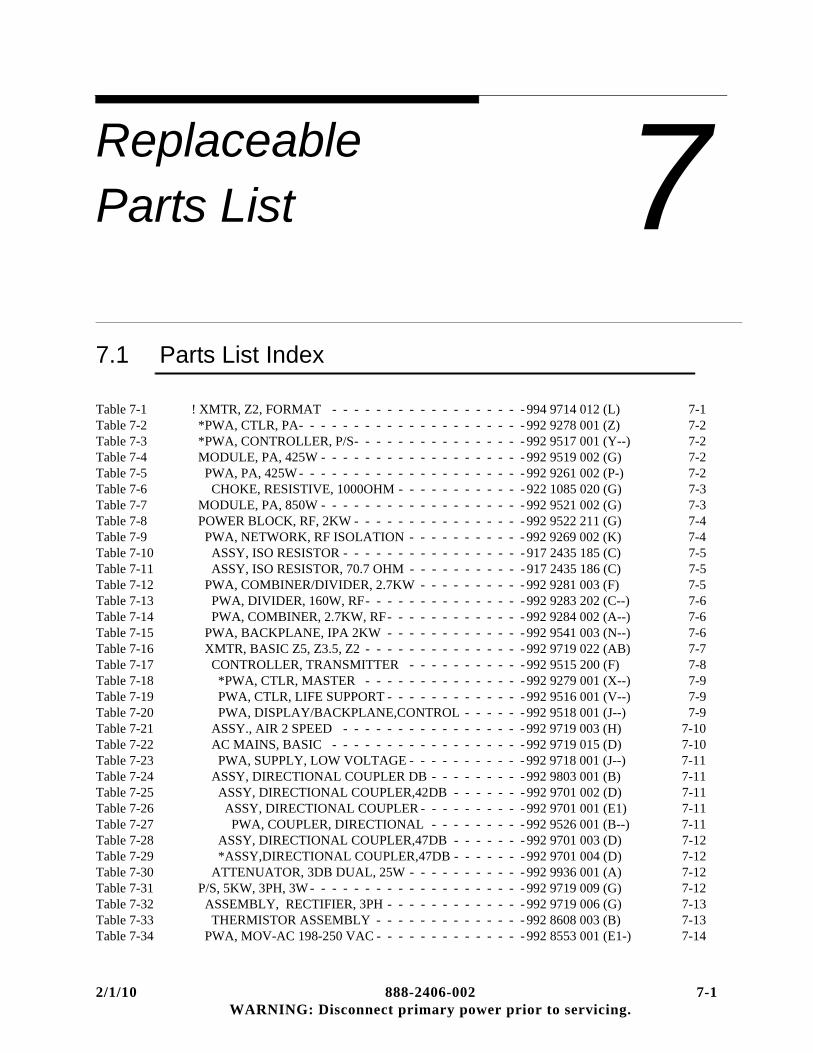
ReplaceableParts List
2/1/10 888-2406-002WARNING: Disconnect primary power prior
7
7.1 Parts List IndexTable 7-1 ! XMTR, Z2, FORMAT - - - - - - - - - - - - - - - - - - 994 9714 012 (L) 7-1Table 7-2 *PWA, CTLR, PA- - - - - - - - - - - - - - - - - - - - - 992 9278 001 (Z) 7-2Table 7-3 *PWA, CONTROLLER, P/S- - - - - - - - - - - - - - - - 992 9517 001 (Y--) 7-2Table 7-4 MODULE, PA, 425W - - - - - - - - - - - - - - - - - - - 992 9519 002 (G) 7-2Table 7-5 PWA, PA, 425W - - - - - - - - - - - - - - - - - - - - - 992 9261 002 (P-) 7-2Table 7-6 CHOKE, RESISTIVE, 1000OHM - - - - - - - - - - - - 922 1085 020 (G) 7-3Table 7-7 MODULE, PA, 850W - - - - - - - - - - - - - - - - - - - 992 9521 002 (G) 7-3Table 7-8 POWER BLOCK, RF, 2KW - - - - - - - - - - - - - - - - 992 9522 211 (G) 7-4Table 7-9 PWA, NETWORK, RF ISOLATION - - - - - - - - - - - 992 9269 002 (K) 7-4Table 7-10 ASSY, ISO RESISTOR - - - - - - - - - - - - - - - - - 917 2435 185 (C) 7-5Table 7-11 ASSY, ISO RESISTOR, 70.7 OHM - - - - - - - - - - - 917 2435 186 (C) 7-5Table 7-12 PWA, COMBINER/DIVIDER, 2.7KW - - - - - - - - - - 992 9281 003 (F) 7-5Table 7-13 PWA, DIVIDER, 160W, RF- - - - - - - - - - - - - - - 992 9283 202 (C--) 7-6Table 7-14 PWA, COMBINER, 2.7KW, RF- - - - - - - - - - - - - 992 9284 002 (A--) 7-6Table 7-15 PWA, BACKPLANE, IPA 2KW - - - - - - - - - - - - - 992 9541 003 (N--) 7-6Table 7-16 XMTR, BASIC Z5, Z3.5, Z2 - - - - - - - - - - - - - - - 992 9719 022 (AB) 7-7Table 7-17 CONTROLLER, TRANSMITTER - - - - - - - - - - - 992 9515 200 (F) 7-8Table 7-18 *PWA, CTLR, MASTER - - - - - - - - - - - - - - - 992 9279 001 (X--) 7-9Table 7-19 PWA, CTLR, LIFE SUPPORT - - - - - - - - - - - - - 992 9516 001 (V--) 7-9Table 7-20 PWA, DISPLAY/BACKPLANE,CONTROL - - - - - - 992 9518 001 (J--) 7-9Table 7-21 ASSY., AIR 2 SPEED - - - - - - - - - - - - - - - - - 992 9719 003 (H) 7-10Table 7-22 AC MAINS, BASIC - - - - - - - - - - - - - - - - - - 992 9719 015 (D) 7-10Table 7-23 PWA, SUPPLY, LOW VOLTAGE - - - - - - - - - - - 992 9718 001 (J--) 7-11Table 7-24 ASSY, DIRECTIONAL COUPLER DB - - - - - - - - - 992 9803 001 (B) 7-11Table 7-25 ASSY, DIRECTIONAL COUPLER,42DB - - - - - - - 992 9701 002 (D) 7-11Table 7-26 ASSY, DIRECTIONAL COUPLER - - - - - - - - - - 992 9701 001 (E1) 7-11Table 7-27 PWA, COUPLER, DIRECTIONAL - - - - - - - - - 992 9526 001 (B--) 7-11Table 7-28 ASSY, DIRECTIONAL COUPLER,47DB - - - - - - - 992 9701 003 (D) 7-12Table 7-29 *ASSY,DIRECTIONAL COUPLER,47DB - - - - - - - 992 9701 004 (D) 7-12Table 7-30 ATTENUATOR, 3DB DUAL, 25W - - - - - - - - - - - 992 9936 001 (A) 7-12Table 7-31 P/S, 5KW, 3PH, 3W - - - - - - - - - - - - - - - - - - - - 992 9719 009 (G) 7-12Table 7-32 ASSEMBLY, RECTIFIER, 3PH - - - - - - - - - - - - - 992 9719 006 (G) 7-13Table 7-33 THERMISTOR ASSEMBLY - - - - - - - - - - - - - - 992 8608 003 (B) 7-13Table 7-34 PWA, MOV-AC 198-250 VAC - - - - - - - - - - - - - - 992 8553 001 (E1-) 7-14
7-1 to servicing.

Replaceable Parts List
Table 7-35 P/S, 5KW, 3PH, 4W - - - - - - - - - - - - - - - - - - - - 992 9719 010 (G1) 7-14Table 7-36 PWA, MOV-AC 342-432 VAC - - - - - - - - - - - - - - 992 8553 003 (B1-) 7-14Table 7-37 P/S, 2.5KW, 3PH, 3W - - - - - - - - - - - - - - - - - - - 992 9719 011 (H) 7-15Table 7-38 P/S, 2.5KW, 3PH, 4W - - - - - - - - - - - - - - - - - - - 992 9719 012 (H) 7-15Table 7-39 P/S, 1PH, Z5, Z3.5, & Z2R- - - - - - - - - - - - - - - - 992 9719 023 (C) 7-16Table 7-40 P/S, 5KW, 1PH - - - - - - - - - - - - - - - - - - - - - 992 9719 013 (K) 7-16Table 7-41 PWA, P/S RECTIFIER, 1 PH - - - - - - - - - - - - - - 992 9762 001 (V) 7-17Table 7-42 THERMISTOR ASSEMBLY - - - - - - - - - - - - - 992 8608 004 (B) 7-18Table 7-43 P/S, 1PH, Z2 (NON-REDUNDANT) - - - - - - - - - - - - 992 9719 024 (C) 7-19Table 7-44 P/S, 2.5KW, 1 PH - - - - - - - - - - - - - - - - - - - - 992 9719 014 (L) 7-19
Table 7-1 ! XMTR, Z2, FORMAT - 994 9714 012 (L)Harris PN Description Qty UM Ref Des570 0329 000 *CONTACTOR 90A 3-POLE 60HZ 0 EA UNIT 1 K1570 0372 000 CONTACTOR 90A 3 POLE 50HZ 0 EA UNIT 1 K1917 2435 125 KIT,FRMWR,3PH,Z2 0 EA917 2435 126 KIT,FRMWR,1PH,Z2 0 EA917 2435 165 KIT,FRMWR,3PH,Z2R 0 EA917 2435 166 KIT,FRMWR,1PH,Z2R 0 EA939 8168 152 PANEL, BLANK 0 EA943 5467 144 ADAPTOR, EXHAUST DUCT 0 EA943 5467 232 ADAPTOR, 3-1/8 TO 1/5/8 1 EA971 0001 029 KIT, MICROMAX, SINGLE EXCITER 0 EA971 0001 030 KIT, MICROMAX, DUAL EXCITER 0 EA988 2406 005 DP, PLATINUM Z2 1 EA992 9278 001 *PWA, CTLR, PA 0 EA UNIT 1 A1A3992 9517 001 *PWA, CONTROLLER, P/S 0 EA UNIT 1 A1A7992 9519 002 MODULE, PA, 425W 8 EA UNIT 1 A3-A10992 9521 002 MODULE, PA, 850W 1 EA UNIT 1 A11992 9522 211 POWER BLOCK, RF, 2KW 1 EA UNIT 1 A2992 9719 009 P/S, 5KW, 3PH, 3W 0 EA UNIT 1 A17992 9719 010 P/S, 5KW, 3PH, 4W 0 EA UNIT 1 A17992 9719 011 P/S, 2.5KW, 3PH, 3W 0 EA UNIT 1 A17992 9719 012 P/S, 2.5KW, 3PH, 4W 0 EA UNIT 1 A17992 9719 023 P/S, 1PH, Z5, Z3.5, & Z2R 0 EA UNIT 1 A17992 9719 024 P/S, 1PH, Z2 (NON-REDUNDANT) 0 EA UNIT 1 A17992 9719 033 P/S, 5KW, 480VAC, 3PH, 3W 0 EA UNIT 1 A17992 9719 034 P/S, 2.5KW, 480VAC, 3PH, 3W 0 EA UNIT 1 A17992 9766 001 KIT, 5,3.5,2KW SERV PARTS 0 EA992 9767 001 KIT, PLAT Z, 1PH SEMICOND,FUSE 0 EA992 9767 003 KIT, PLAT Z, 3PH SEMICOND,FUSE 0 EA992 9768 002 ! KIT, PLATINUM Z BOARDS 0 EA992 9851 050 KIT, CE, SINGLE EXCITER 0 EA992 9851 051 KIT, CE, DUAL EXCITER 0 EA992 9851 053 KIT, CE, MICROMAX, SINGLE EXCITER, Z 0 EA992 9851 054 KIT, CE, MICROMAX, DUAL EXCITER, Z 0 EA994 9410 005 ! EXCITER, DIGIT CD 0 EA A15 A16994 9678 002 ! EXCITER, SUPERCITER 0 EA A15 A16994 9807 015 FREQ CNTRL KIT, PLAT Z 0 EAHARMICROMAXANALOGMICROMAX EXCITER ANALOG AUDIO 0 EAA15 A16HARMICROMAXDIGITALMICROMAX EXCITER DIGITAL AUDIO 0 EAA15 A16
7-2 888-2406-002 2/1/10 WARNING: Disconnect primary power prior to servicing.

Replaceable Parts List
Table 7-2 *PWA, CTLR, PA - 992 9278 001 (Z)Harris PN Description Qty UM Ref Des610 0980 000 *HDR 20C 2ROW RT ANG TOP LATCH 2 EA J001 J002610 0983 000 *HDR 26C 2ROW RT ANG TOP LATCH 2 EA J011 J012817 2435 152 FIRMWARE MATRIX 0 DWG992 9278 002 *PWA, CTLR PA, SMT 1 EA
Table 7-3 *PWA, CONTROLLER, P/S - 992 9517 001 (Y--)Harris PN Description Qty UM Ref Des610 0900 000 HDR, 3C VERT 1ROW UNSHR 2 EA JP001 JP002610 0983 000 *HDR 26C 2ROW RT ANG TOP LATCH 2 EA J001 J002612 1184 000 JUMPER SHUNT, 2C, 0.1’’ PITCH 2 EA646 2110 000 BARCODE, SN_ITEM_REV 1 EA817 2435 152 FIRMWARE MATRIX 0 DWG817 2572 029 FIRMWARE MATRIX, ZHD/ZHD+ 0 DWG992 9517 002 *PWA, CONTROLLER P/S, SMT 1 EA
Table 7-4 MODULE, PA, 425W - 992 9519 002 (G)Harris PN Description Qty UM Ref Des302 0051 000 SCREW, PHMS 4-40 X 3/16 SST 8 EA302 0411 000 SCR, 6-32 X 3/8 16 EA314 0003 000 LOCKWASHER, SPLIT #4 SST (ANSI) 8 EA314 0005 000 LOCKWASHER, SPLIT #6 SST (ANSI) 16 EA357 0128 000 BUTTON, GLIDE, NYLON, 0.75 DIA 4 EA404 0899 007 PAD, THERMAL INTERFACE 1 EA448 1081 000 GASKET, EMI/RFI SHIELDING 1.25 FT646 0665 000 LABEL, INSPECTION 1 EA922 1260 164 SPREADER, DUMMY, 425W PA 1 EA943 5567 766 ASSY, STACKED FIN HEATSINK 1 EA943 5567 888 SHIELD, PA 2 EA992 9261 002 PWA, PA, 425W 1 EA A1
Table 7-5 PWA, PA, 425W - 992 9261 002 (P-)Harris PN Description Qty UM Ref Des550100005 *THERMAL COMPOUND, 8OZ JAR 0 EA #Q001 #Q002860004054 SOLDER, SN63/PB37, 0.032 0 EA860004055 SOLDER, SN62/PB36/AG2, 0.032 0 EA #C031254 0002 000 BUS WIRE, 20AWG, SOLID TINNED CU 0 FT L005254 0055 000 WIRE, 16AWG, SOLID, 600V 0.1 FT302 0441 000 SCREW, SHMS 4-40 X 3/8 SST 4 EA302 0814 004 SCREW, SEMS PPHMS 4-40 X 1/4 3 EA314 0003 000 LOCKWASHER, SPLIT #4 SST (ANSI) 4 EA354 0055 000 SOLDER LUG 6 MTG HOLE 4 EA358 3698 000 JUMPER, 0.85 LG, 1/8 HIGH 2 EA385 0002 001 DIODE, RECT SMB4004/S2G 1 EA CR001500 1231 000 CAP 47PF 10% 500VDC CLAD 1 EA C020500 1327 000 CAP 200PF 500V 10% CLAD 1 EA C010500 1354 000 CAP 91PF 5% 250VDC CLAD 2 EA C008 C009500 1359 000 CAP 150PF 5% 300V 1 EA C032500 1379 000 CAP, MICA VAR 8-45PF 175V 1 EA C001500 1381 000 CAP, MICA VAR 16-100PF 250V 1 EA C019515 0128 000 *CAP 0.01UF 1206 X7R 100V 10% 3 EA C004 C022 C023515 0131 000 *CAP 10PF 1206 C0G 100V 5% 1 EA C003515 0135 301 *CAP 1000PF 1206 C0G 100V 5% 3 EA C005 C025 C028515 0137 301 *CAP 1000PF 1206 X7R 200V 10% 2 EA C015 C021
2/1/10 888-2406-002 7-3 WARNING: Disconnect primary power prior to servicing.
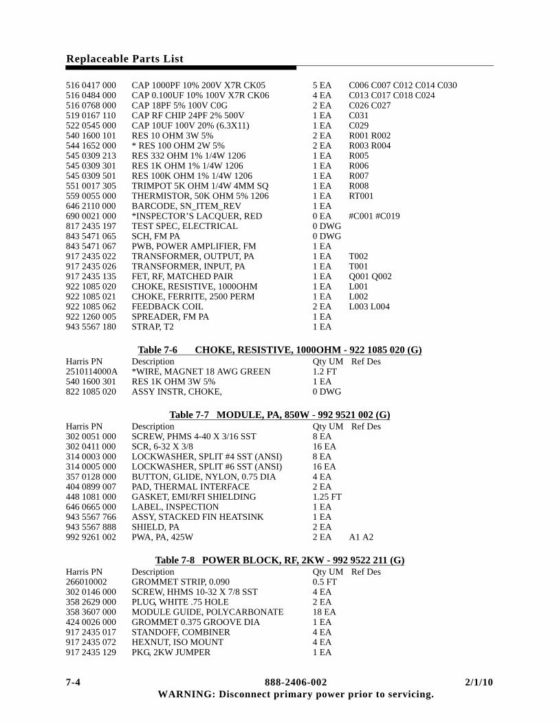
Replaceable Parts List
516 0417 000 CAP 1000PF 10% 200V X7R CK05 5 EA C006 C007 C012 C014 C030516 0484 000 CAP 0.100UF 10% 100V X7R CK06 4 EA C013 C017 C018 C024516 0768 000 CAP 18PF 5% 100V C0G 2 EA C026 C027519 0167 110 CAP RF CHIP 24PF 2% 500V 1 EA C031522 0545 000 CAP 10UF 100V 20% (6.3X11) 1 EA C029540 1600 101 RES 10 OHM 3W 5% 2 EA R001 R002544 1652 000 * RES 100 OHM 2W 5% 2 EA R003 R004545 0309 213 RES 332 OHM 1% 1/4W 1206 1 EA R005545 0309 301 RES 1K OHM 1% 1/4W 1206 1 EA R006545 0309 501 RES 100K OHM 1% 1/4W 1206 1 EA R007551 0017 305 TRIMPOT 5K OHM 1/4W 4MM SQ 1 EA R008559 0055 000 THERMISTOR, 50K OHM 5% 1206 1 EA RT001646 2110 000 BARCODE, SN_ITEM_REV 1 EA690 0021 000 *INSPECTOR’S LACQUER, RED 0 EA #C001 #C019817 2435 197 TEST SPEC, ELECTRICAL 0 DWG843 5471 065 SCH, FM PA 0 DWG843 5471 067 PWB, POWER AMPLIFIER, FM 1 EA917 2435 022 TRANSFORMER, OUTPUT, PA 1 EA T002917 2435 026 TRANSFORMER, INPUT, PA 1 EA T001917 2435 135 FET, RF, MATCHED PAIR 1 EA Q001 Q002922 1085 020 CHOKE, RESISTIVE, 1000OHM 1 EA L001922 1085 021 CHOKE, FERRITE, 2500 PERM 1 EA L002922 1085 062 FEEDBACK COIL 2 EA L003 L004922 1260 005 SPREADER, FM PA 1 EA943 5567 180 STRAP, T2 1 EA
Table 7-6 CHOKE, RESISTIVE, 1000OHM - 922 1085 020 (G)Harris PN Description Qty UM Ref Des2510114000A *WIRE, MAGNET 18 AWG GREEN 1.2 FT540 1600 301 RES 1K OHM 3W 5% 1 EA822 1085 020 ASSY INSTR, CHOKE, 0 DWG
Table 7-7 MODULE, PA, 850W - 992 9521 002 (G)Harris PN Description Qty UM Ref Des302 0051 000 SCREW, PHMS 4-40 X 3/16 SST 8 EA302 0411 000 SCR, 6-32 X 3/8 16 EA314 0003 000 LOCKWASHER, SPLIT #4 SST (ANSI) 8 EA314 0005 000 LOCKWASHER, SPLIT #6 SST (ANSI) 16 EA357 0128 000 BUTTON, GLIDE, NYLON, 0.75 DIA 4 EA404 0899 007 PAD, THERMAL INTERFACE 2 EA448 1081 000 GASKET, EMI/RFI SHIELDING 1.25 FT646 0665 000 LABEL, INSPECTION 1 EA943 5567 766 ASSY, STACKED FIN HEATSINK 1 EA943 5567 888 SHIELD, PA 2 EA992 9261 002 PWA, PA, 425W 2 EA A1 A2
Table 7-8 POWER BLOCK, RF, 2KW - 992 9522 211 (G)Harris PN Description Qty UM Ref Des266010002 GROMMET STRIP, 0.090 0.5 FT302 0146 000 SCREW, HHMS 10-32 X 7/8 SST 4 EA358 2629 000 PLUG, WHITE .75 HOLE 2 EA358 3607 000 MODULE GUIDE, POLYCARBONATE 18 EA424 0026 000 GROMMET 0.375 GROOVE DIA 1 EA917 2435 017 STANDOFF, COMBINER 4 EA917 2435 072 HEXNUT, ISO MOUNT 4 EA917 2435 129 PKG, 2KW JUMPER 1 EA
7-4 888-2406-002 2/1/10 WARNING: Disconnect primary power prior to servicing.

Replaceable Parts List
917 2435 148 CABLE, Z2 1 EA917 2435 219 LABEL, PA OUTLINE, Z5/Z2/Z4/Z8 1 EA922 1260 165 PLATE, AIR BLOCK, Z2 2 EA922 1260 191 COVER, FEEDTHRU PCB 5 EA922 1312 194 PLATE, CLOSEOUT 1 EA939 8168 141 CLOSEOUT PLATE, Z2 FILTER BDS 1 EA943 5467 161 PNL, LT INNER/RT OUTER REAR 1 EA943 5467 168 PNL, RT INR/LT OUTER REAR 1 EA992 9269 002 PWA, NETWORK, RF ISOLATION 1 EA A2A4992 9281 003 PWA, COMBINER/DIVIDER, 2.7KW 1 EA A2A3992 9523 200 XMSN LINE, 2KW 1 EA A2A5992 9541 003 PWA, BACKPLANE, IPA 2KW 1 EA A2A12992 9719 022 XMTR, BASIC Z5, Z3.5, Z2 1 EA992 9756 001 PWA, 20 CONDUCTOR FILTER 3 EA A20A2 A20A7 A20A10992 9756 101 PWA, 26 CONDUCTOR FILTER 2 EA A20A4 A20A9
Table 7-9 PWA, NETWORK, RF ISOLATION - 992 9269 002 (K)Harris PN Description Qty UM Ref Des328 0074 000 WASHER, BELLEVILLE 0.153 ID, STEEL 4 EA336 1245 000 PIN, CONTACT 0.093 OD 0.045 ID 16 EA358 3524 000 PIN PRINTED CIRCUIT BOARD 10 EA E001 E002 E003 E004 E005 E006
E007 E008 E009 E010382 1502 000 IC, L603C, 8 DRIVER, ESD 1 EA U001384 0854 000 DIODE ARRAY, 8 ISOLATED ESD 1 EA CR009404 0766 000 SOCKET, DIP, 18 PIN (DL) 1 EA XU001492 0768 000 IND, HORIZ, 709NH 5% (6X10MM) 8 EA L001 L002 L003 L004 L005 L006
L007 L008515 0078 000 *CAP 1000PF 1206 X7R 50V 10% 39 EA C001 C002 C003 C004 C005 C006
C007 C008 C009 C010 C011 C012 C013 C014 C015 C016 C017 C018 C019 C020 C031 C032 C033 C034 C035 C036 C037 C038 C039 C040 C041 C042 C043 C044 C045 C046 C047 C048 C049
519 0050 000 <*>CAP RF CHIP 100PF 5% 500V 8 EA C029 C030 C050 C051 C052 C053 C054 C055
545 0309 319 RES 5.62K OHM 1% 1/4W 1206 1 EA R010574 0551 000 RELAY, SPDT, 48VDC, 10 AMP 8 EA K001 K002 K003 K004 K005 K006
K007 K008610 0877 000 HDR, 2C VERT 1ROW UNSHR 2 EA JP001 JP002610 0981 000 *HDR 20C 2ROW VERT TOP LATCH 2 EA J001 J002612 1184 000 JUMPER SHUNT, 2C, 0.1’’ PITCH 2 EA646 0665 000 LABEL, INSPECTION 0 EA646 2110 000 BARCODE, SN_ITEM_REV 1 EA843 5471 271 SCH, ISOLATION BOARD 0 DWG843 5471 273 PWB, ISOLATION 1 EA917 2435 185 ASSY, ISO RESISTOR 8 EA RT001 RT002 RT003 RT004 RT005
RT006 RT007 RT008917 2435 186 ASSY, ISO RESISTOR, 70.7 OHM 1 EA R009939 8168 069 ANGLE, ISO CHASSIS 2 EA939 8168 070 COVER, ISO CHASSIS 1 EA943 5467 172 CHASSIS, ISO BOARD 1 EA999 2872 001 HARDWARE LIST, PWA NETWORK 1 EA943 5467 060 HEATSINK, ISO BD 1 EA
2/1/10 888-2406-002 7-5 WARNING: Disconnect primary power prior to servicing.

Replaceable Parts List
Table 7-10 ASSY, ISO RESISTOR - 917 2435 185 (C)Harris PN Description Qty UM Ref Des817 2435 185 ASSY INSTR, ISO RESISTOR 0 DWG540 1550 000 RES 50 OHM, 12W 10% 1 EA559 0056 000 THERMISTOR, 50K @25C 5% 1 EA690 0023 000 EPOXY, ADHESIVE, ONE COMPONENT 0 EA
Table 7-11 ASSY, ISO RESISTOR, 70.7 OHM - 917 2435 186 (C)Harris PN Description Qty UM Ref Des550190009 *RTV SILICONE, CLEAR, DOW 3140 0 EA640002001 *RESIN, THERMAL EPOXY (2-PART) 0 OZ640002002 *CATALYST, THERMAL EPOXY (CAT-190) 0 OZ296 0309 000 TUBING, TEFLON 24AWG THIN WALL 0.17 FT515 0078 000 *CAP 1000PF 1206 X7R 50V 10% 1 EA544 1675 000 RESISTOR 70.7 OHM 400W 1 EA559 0053 000 THERMISTOR, NTC 10K OHM 1% 1 EA817 2435 186 ASSY INSTR, ISO RES, 70.7 OHM 0 DWG
Table 7-12 PWA, COMBINER/DIVIDER, 2.7KW - 992 9281 003 (F)Harris PN Description Qty UM Ref Des254 0001 000 BUS WIRE, 22AWG, SOLID TINNED CU 8 FT302 0106 000 SCR, 6-32 X 3/8 4 EA306 0016 000 NUT, HEX KEP, 6-32 SST 4 EA336 1245 000 PIN, CONTACT 0.093 OD 0.045 ID 18 EA350 0108 000 RIVET .094 DIA X .500 LG 6 EA540 1550 000 RES 50 OHM, 12W 10% 8 EA R001 R002 R003 R004 R005 R006
R007 R008540 1551 000 RES 70.7 OHM, 12W @40 DEG C 1 EA R009612 1599 000 CONN, EDGECARD 18POS 2ROW 8 EA J001 J002 J003 J004 J005 J006 J007
J008620 2873 000 CONN PANEL 7/16 (MALE) 1 EA J010646 0665 000 LABEL, INSPECTION 1 EA646 2110 000 BARCODE, SN_ITEM_REV 1 EA817 2435 197 TEST SPEC, ELECTRICAL 0 DWG917 2435 094 CLIP, Z-PLANE GROUND 16 EA917 2435 160 COVER, 7/16 CONNECTOR 1 EA917 2435 187 PLATE COAX CONN, Z PLANE BOARD 2 EA917 2435 188 ELEMENT, CAPACITIVE, 1 EA917 2435 189 ELEMENT, CAPACITIVE, 2 EA992 9283 202 PWA, DIVIDER, 160W, RF 1 EA992 9284 002 PWA, COMBINER, 2.7KW, RF 1 EA
Table 7-13 PWA, DIVIDER, 160W, RF - 992 9283 202 (C--)Harris PN Description Qty UM Ref Des384 0854 000 DIODE ARRAY, 8 ISOLATED ESD 1 EA CR001404 0675 000 SOCKET, DIP, 16 PIN (DL) 2 EA #CR001 #R009516 0736 000 CAP 1000PF 10% 100V X7R 8 EA C001 C002 C003 C004 C005 C006
C007 C008519 0019 000 <*>CAP RF CHIP 5.1PF +-.25PF 500V 1 EA C009519 0030 000 <*>CAP RF CHIP 15PF 5% 500V 1 EA C010540 1366 000 RES NETWORK 100 OHM 2% 1 EA R009542 1603 000 RES, 0.01 OHM, 3W 1% 8 EA R01 1 R012 R013 R014 R015 R016
R017 R018560 0121 010 POSISTOR 0.9 AMP 60VDC 12MM DISC 4 EA F001 F002 F003 F004
7-6 888-2406-002 2/1/10 WARNING: Disconnect primary power prior to servicing.

Replaceable Parts List
610 0933 000 TEST POINT, OVAL-LOOP THRU 1 EA TP001610 0982 000 *HDR 26C 2ROW VERT TOP LATCH 2 EA J011,J012610 1121 000 HDR, 4C VERT 2ROW UNSHR 1 EA JP001612 1184 000 JUMPER SHUNT, 2C, 0.1’’ PITCH 2 EA620 2023 000 RECEPTACLE, BNC VERT PCB 1 EA J009646 2110 000 BARCODE, SN_ITEM_REV 1 EA843 5471 281 SCH, DIVIDER 0 DWG843 5471 283 PWB, DIVIDER 1 EA
Table 7-14 PWA, COMBINER, 2.7KW, RF - 992 9284 002 (A--)Harris PN Description Qty UM Ref Des358 3525 000 PIN RECEPTACLE 10 EA E001 E002 E003 E004 E005 E006
E007 E008 E009 E010646 2110 000 BARCODE, SN_ITEM_REV 1 EA843 5471 291 SCH, COMBINER 0 DWG843 5471 293 PWB, COMBINER 1 EA
Table 7-15 PWA, BACKPLANE, IPA 2KW - 992 9541 003 (N--)Harris PN Description Qty UM Ref Des2520420000A WIRE RIBBON SILVER 0.005 X 0.100 0.17 FT254 0001 000 BUS WIRE, 22AWG, SOLID TINNED CU 2.57 FT296 0310 000 TUBING, TEFLON 20AWG THIN WALL 0.124 FT358 2684 000 STANDOFF, PEM, 4-40 X 0.125 (KFSE-440-4) 6 EA382 1502 000 IC, L603C, 8 DRIVER, ESD 1 EA U001384 0321 000 *DIODE, SCHOTTKY, 5082-2800 1 EA CR001404 0766 000 SOCKET, DIP, 18 PIN (DL) 1 EA XU001516 0736 000 CAP 1000PF 10% 100V X7R 9 EA C001 C002 C004 C005 C006 C007
C008 C009 C012540 1600 308 RES 2K OHM 3W 5% 1 EA R003542 1603 000 RES, 0.01 OHM, 3W 1% 1 EA R001545 0309 201 RES 100 OHM 1% 1/4W 1206 1 EA R002548 2400 201 RES 100 OHM 1/2W 1% 1 EA R005559 0053 000 THERMISTOR, NTC 10K OHM 1% 2 EA RT001 RT002560 0121 010 POSISTOR 0.9 AMP 60VDC 12MM DISC 2 EA F001 F002574 0551 001 RELAY, SPDT, 48VDC 16 AMP 3 EA K001 K002 K003610 0933 000 TEST POINT, OVAL-LOOP THRU 2 EA TP002 TP006610 0981 000 *HDR 20C 2ROW VERT TOP LATCH 1 EA J007612 1599 000 CONN, EDGECARD 18POS 2ROW 2 EA J001 J002620 1677 001 JACK, BNC STRAIGHT PCB 5 EA J003 J004 J005 J006 J008646 2110 000 BARCODE, SN_ITEM_REV 1 EA843 5467 070 PWB, IPA BACKPLANE GND 2 EA843 5471 201 SCH, IPA BACKPLANE 0 DWG843 5471 203 PWB, IPA BACKPLANE 1 EA999 2871 001 HARDWARE LIST, IPA BACKPLANE 1 EA
Table 7-16 XMTR, BASIC Z5, Z3.5, Z2 - 992 9719 022 (AB)Harris PN Description Qty UM Ref Des74030002 FINGER STOCK 0097-0542-02 0.35 EA74030021 BRZ, FGR STK 97-500-04 5 EA74060029 BRZ, FINGERS TWIST 97-560 36 IN74060079 BRZ, FGR STK, CLIP ON, REV BEND 18.5 EA266010003 GROMMET STRIP, 0.125 7.3 FT356 0208 000 CLAMP, FLAT CABLE 2 17 EA356 0214 000 CLAMP, FLAT CABLE 1 IN. 2 EA358 0498 000 *HOSE CLAMP, SST, SAE-48 4 EA358 2598 000 CABLE TIE MOUNT, 4-WAY 6 EA
2/1/10 888-2406-002 7-7 WARNING: Disconnect primary power prior to servicing.

Replaceable Parts List
358 3817 001 JACKSCREW, 4-40 FEMALE HEX 2 EA TB001398 0760 020 FUSE, CART 0.25X1.25 20A SLOW 1 EA F1402 0203 000 FUSEHOLDER 3AG SHOCKSAFE 1 EA424 0023 000 GROMMET 1.000 GROOVE DIA 3 EA424 0025 000 GROMMET 0.563 GROOVE DIA 2 EA424 0026 000 GROMMET 0.375 GROOVE DIA 1 EA448 0254 000 FASTENER, RIGHT HAND 3 EA620 0455 000 ADAPTER, BNC JACK-JACK 2 EA A2J3 A2J4646 1353 000 NAMEPLATE, XMTR EQUIPMENT 1 EA917 2435 045 PANEL, ACCESS 1 EA917 2435 047 PLATE, SINK 1 EA917 2435 057 SPACER, P/S DOCKING 2 EA917 2435 237 SPACER, IPA 1 EA917 2558 080 PATENT LABEL - FM XMTRS 1 EA922 1260 023 SIDE, LEFT, DUCT 1 EA922 1260 024 SIDE, RIGHT, DUCT 1 EA922 1260 025 FRONT, DUCT 1 EA922 1260 043 GUIDE, MODIFIED 2 EA922 1260 057 BASE, DUCT 1 EA922 1260 062 ANGLE, P/S SHIPPING 2 EA922 1260 113 BRACKET, FEED-THRU 1 EA922 1260 142 STRAP, GROUND, 2 FT LONG 1 EA922 1260 156 AIR PLATE, IPA DUCT 1 EA922 1260 157 CLOSEOUT, IPA DUCT 1 EA922 1260 187 BRKT, LT INNER/RT OUTER 1 EA922 1260 188 BRKT, RT INNER/LT OUTER 1 EA922 1260 192 BRKT LT INNER/RT OUTER REAR 1 EA922 1260 193 BRKT RT INNER/LT OUTER REAR 1 EA922 1260 206 DAM, AIR 1 EA922 1260 214 COVER, CHASSIS REAR 2 EA922 1260 223 DEFLECTOR, AIR COOLED RESISTOR 2 EA922 1260 232 COVER, 3-1/8 FLANGE 1 EA939 8168 021 FACEPLATE, IPA MODULE 1 EA939 8168 031 BRKT, 10KW COMBINER SUPPORT 2 EA939 8168 036 ANGLE, EIA, POWER SUPPLY 2 EA939 8168 043 PANEL, SIDE, COMBINER COVER 1 EA939 8168 058 PLATE, CLOSEOUT 1 EA939 8168 060 ANGLE, SLIDE, L/R 2 EA939 8168 061 SPACER, RECT, L/R 2 EA939 8168 065 ANGLE, GASKET MTG 1 EA939 8168 067 ANGLE, GASKET MTG 2 EA939 8168 155 SIDE, COMBINER SHIELD, 10KW 1 EA939 8168 166 TOP, COMBINER SHIELD, 10KW 1 EA939 8168 170 PANEL, FRONT MTG 2 EA939 8168 181 CHASSIS, REAR 1 EA939 8168 182 CHASSIS, FRONT 1 EA939 8168 185 ANGLE, FACE PLATE 2 EA939 8168 186 ANGLE, GASKET MTG 2 EA939 8168 187 ANGLE, RFI, PB DOOR 1 EA939 8168 188 PLATE, CLOSEOUT 1 EA939 8168 192 DECK, UPPER CENTER 1 EA939 8168 193 PLATE, UPPER REAR DECK 1 EA939 8168 294 ANGLE, EIA, POWER BLOCK, RT 1 EA939 8168 299 CLOSEOUT, RIGHT SIDE, 1 EA939 8168 309 BRACKET, REAR SHIELD 1 EA939 8168 310 CLOSEOUT, LEFT SIDE, 1 EA943 5467 022 PLT,CLOSEOUT,LOWER SHELF,FRONT 1 EA
7-8 888-2406-002 2/1/10 WARNING: Disconnect primary power prior to servicing.
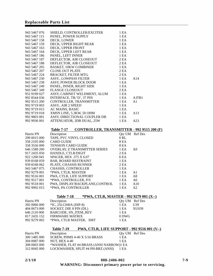
Replaceable Parts List
943 5467 076 SHIELD, CONTROLLER/EXCITER 1 EA943 5467 115 PANEL, POWER SUPPLY 1 EA943 5467 158 DECK, LOWER 1 EA943 5467 159 DECK, UPPER RIGHT REAR 1 EA943 5467 163 DECK, UPPER FRONT 1 EA943 5467 164 DECK, UPPER LEFT REAR 1 EA943 5467 186 PANEL, LEFT INNER 1 EA943 5467 187 DEFLECTOR, AIR CLOSEOUT 2 EA943 5467 188 DEFLECTOR, AIR CLOSEOUT 2 EA943 5467 205 BASKET, 10KW COMBINER 1 EA943 5467 207 CLOSE OUT PLATE 2 EA943 5467 224 BRACKET, FILTER MTG. 2 EA943 5467 230 ASSY., LOWPASS FILTER 1 EA A14943 5467 238 ASSY, POWER BLOCK DOOR 1 EA943 5467 249 PANEL, INNER, RIGHT SIDE 1 EA943 5467 349 FLANGE CLOSEOUT 2 EA952 9199 027 ASSY, CABINET WELDMENT, ALUM 1 EA992 8544 036 INTERFACE, TB:’D’, 37 PIN 1 EA A1TB1992 9515 200 CONTROLLER, TRANSMITTER 1 EA A1992 9719 003 ASSY., AIR 2 SPEED 1 EA992 9719 015 AC MAINS, BASIC 1 EA992 9719 018 XMSN LINE, 5.3KW, 50 OHM 1 EA A13992 9803 001 ASSY, DIRECTIONAL COUPLER DB 1 EA992 9936 001 ATTENUATOR, 3DB DUAL, 25W 1 EA A23
Table 7-17 CONTROLLER, TRANSMITTER - 992 9515 200 (F)Harris PN Description Qty UM Ref Des299 0015 000 TAPE, PVC VINYL CLOSED 0 RL358 2105 000 CARD GUIDE 8 EA358 3556 000 TENSION CARD GUIDE 8 EA646 1589 200 OVERLAY, Z TRANSMITTER SERIES 1 EA A9917 2435 050 HANDLE, CTLR/DIGIT 2 EA922 1260 041 SPACER, HEX .375 X 6.07 6 EA939 8168 059 BAR, BOARD RESTRAINT 1 EA939 8168 062 PLATE, CHASSIS RUNNER 2 EA943 5467 075 CHASSIS, CONTROLLER 1 EA992 9279 001 *PWA, CTLR, MASTER 1 EA A1992 9516 001 PWA, CTLR, LIFE SUPPORT 1 EA A8992 9517 001 *PWA, CONTROLLER, P/S 1 EA A6992 9518 001 PWA, DISPLAY/BACKPLANE,CONTROL 1 EA A10992 9992 015 *PWA, PA CONTROLLER 1 EA A2
Table 7-18 *PWA, CTLR, MASTER - 992 9279 001 (X--)Harris PN Description Qty UM Ref Des392 0066 000 *IC, 25LC040A (DIP-8) 1 EA U39404 0673 000 SOCKET, DIP, 8 PIN (DL) 1 EA XU039646 2110 000 BARCODE, SN_ITEM_REV 1 EA817 2435 152 FIRMWARE MATRIX 0 DWG992 9279 002 *PWA, CTLR MASTER, SMT 1 EA
Table 7-19 PWA, CTLR, LIFE SUPPORT - 992 9516 001 (V--)Harris PN Description Qty UM Ref Des300 1485 000 SCREW, PHMS 4-40 X 5/16 BRASS 1 EA304 0087 000 NUT, HEX 4-40 1 EA308 0003 000 *WASHER, FLAT #4 BRASS (ANSI NARROW)1 EA312 0045 000 LOCKWASHER, SPLIT #4 PH-BRZ (ANSI) 1 EA
2/1/10 888-2406-002 7-9 WARNING: Disconnect primary power prior to servicing.

Replaceable Parts List
358 2997 000 END PLATE, GREY (236) 1 EA J004380 0587 000 XSTR, PNP, MJE210 1 EA Q003382 0406 000 IC, LM340/LM7812C (TO-220) 1 EA U010404 0825 000 SOCKET, DIP16, LO PROFILE 4 EA XK001 XK002 XK003 XK004540 1600 112 RES 30 OHM 3W 5% 1 EA R071548 2400 201 RES 100 OHM 1/2W 1% 4 EA R117 R118 R119 R120574 0485 000 RELAY 2PDT 12VDC 2A LATCHING 4 EA K001 K002 K003 K004610 0900 000 HDR, 3C VERT 1ROW UNSHR 3 EA JP001 JP002 JP003610 1686 010 HDR 10C 2ROW RT ANG TOP LATCH 1 EA J005612 1184 000 JUMPER SHUNT, 2C, 0.1’’ PITCH 3 EA612 1350 000 JACK, SMB STRAIGHT PCB 2 EA J002 J003614 0790 000 TERM BLK, PCB, 1-POLE, GREY (236) 10 EA J004646 2110 000 BARCODE, SN_ITEM_REV 1 EA843 5471 211 SCH, LIFE SUPPORT 0 DWG992 9516 002 *PWA, CTLR, LIFE SUPPORT, SMT 1 EA
Table 7-20 PWA, DISPLAY/BACKPLANE,CONTROL - 992 9518 001 (J--)Harris PN Description Qty UM Ref Des302 0011 000 SCR, 2-56 X 3/16 8 EA310 0036 000 WASHER, FLAT #2 SST (ANSI NARROW) 8 EA314 0001 000 LOCKWASHER, SPLIT #2 SST (ANSI) 8 EA383 0494 000 IC, MM5453 ESD 1 EA U001384 0431 000 *DIODE, RECT 1N4001 2 EA CR001 CR002404 0830 000 SOCKET, PLCC-44, THROUGH HOLE 1 EA XU001404 0851 000 SOCKET, 18 PIN SIP 2 EA406 0527 000 DISPLAY, LCD 4 X 20 1 EA DS001406 0529 000 DISPLAY, LCD 3.5 DIGIT CUSTOM 1 EA DS002516 0453 000 CAP 0.100UF 10% 100V X7R 5 EA C005 C006 C007 C008 C010516 0971 000 CAP 470PF 5% 100V C0G 1 EA C004516 0974 000 CAP 1000PF 5% 100V C0G 82 EA C001 C002 C003 C009 C011 C012
C013 C014 C015 C016 C017 C018 C019 C020 C021 C022 C023 C024 C025 C026 C027 C028 C029 C030 C031 C032 C033 C034 C035 C036 C037 C038 C039 C040 C041 C042 C043 C044 C045 C046 C047 C048 C049 C050 C051 C052 C053 C054 C055 C056 C057 C058 C059 C060 C061 C062 C063 C064 C065 C066 C067 C068 C069 C070 C071 C072 C073 C074 C075 C076 C077 C078 C079 C080 C081 C082 C083 C084 C085 C086 C087 C088
548 2400 369 RES 5.11K OHM 1/2W 1% 1 EA R007548 2400 373 RES 5.62K OHM 1/2W 1% 3 EA R003 R004 R005548 2400 401 RES 10K OHM 1/2W 1% 1 EA R006548 2400 601 RES 1MEG OHM 1/2W 1% 1 EA R001550 0958 000 TRIMPOT 10K OHM 1/2W 10% 1 EA R002604 0935 000 SW, PB SINGLE SECT 1 EA S001610 0893 000 PLUG, ’D’, 25C VERT PCB PLASTIC 1 EA J021610 0900 000 HDR, 3C VERT 1ROW UNSHR 3 EA JP001 JP002 JP003610 0904 000 HDR, 14C VERT 1ROW UNSHR 2 EA J009 J010610 0918 000 HDR, 16C VERT 1ROW UNSHR 1 EA610 0933 000 TEST POINT, OVAL-LOOP THRU 5 EA TP001 TP002 TP003 TP004 TP005610 0981 000 *HDR 20C 2ROW VERT TOP LATCH 3 EA J011 J012 J013610 1083 000 PLUG, ’D’, 37C VERT PCB PLASTIC 1 EA J020610 1106 000 HDR, 8C VERT 1ROW FRICTION 1 EA J014612 1184 000 JUMPER SHUNT, 2C, 0.1’’ PITCH 3 EA
7-10 888-2406-002 2/1/10 WARNING: Disconnect primary power prior to servicing.

Replaceable Parts List
612 1341 000 RECP, ’D’, 15C VERT PCB PLASTIC 2 EA J018 J019612 1350 000 JACK, SMB STRAIGHT PCB 3 EA J015 J016 J017612 1491 000 CONN, EDGECARD 66POS 2ROW 1 EA J008612 1492 000 CONN, EDGECARD 18POS 2ROW 6 EA J002 J003 J004 J005 J006 J007612 1495 000 CONN, EDGECARD 94POS 2ROW 1 EA J001646 2110 000 BARCODE, SN_ITEM_REV 1 EA843 5471 191 SCH, DISPLAY/BACKPLANE,CONTROL 0 DWG843 5471 193 PWB, DISPLAY/BACKPLANE,CONTROL 1 EA917 2435 039 STANDOFF, LCD DISPLAY 4 EA
Table 7-21 ASSY., AIR 2 SPEED - 992 9719 003 (H)Harris PN Description Qty UM Ref Des350 0105 000 RIVET 3/16 ALUM .126/.25 23 EA430 0278 000 FAN BLADE, 20 DIA, 1 EA436 0329 000 MOTOR, 2 SPEED, 50/60HZ 1 EA B1448 1032 000 HINGE, METAL LIFT-OFF 2 EA448 1124 000 LATCH, RAISED, ADJ LEVER 2 EA448 1146 000 AIR FILTER 19.62 X 24.62 X .88 1 EA917 2435 155 CABLE, FAN 1 EA922 1203 819 HANDLE, CONTROLLER 2 EA943 5467 500 FAB PKG, DOOR, UPPER/LOWER 1 EA
Table 7-22 AC MAINS, BASIC - 992 9719 015 (D)Harris PN Description Qty UM Ref Des266010003 GROMMET STRIP, 0.125 0.5 FT354 0223 000 CONNECTOR 70 AMP 1 EA354 0760 000 LUG QC ADAPTER 250 1F/2M N-INS 3 EA424 0016 000 GROMMET 1.125 GROOVE DIA 1 EA424 0031 000 GROMMET 2.500 GROOVE DIA 1 EA574 0388 000 RELAY 240VAC DPDT 1 EA K2606 0816 000 CB, 3 POLE, 10 AMP 250VAC 1 EA CB1917 2435 201 INSULATOR, AC MAIN 1 EA917 2435 949 CABLE, CAB AC DISTRIBUTION 1 EA917 2538 001 PLATE, C B CLOSEOUT 1 EA939 8168 295 COVER, AC DISTRIBUTION 1 EA939 8168 296 CHASSIS, AC DISTRIBUTION 1 EA992 9718 001 PWA, SUPPLY, LOW VOLTAGE 1 EA A19
Table 7-23 PWA, SUPPLY, LOW VOLTAGE - 992 9718 001 (J--)Harris PN Description Qty UM Ref Des384 0341 000 DIODE, RECT 1N5404 4 EA CR001 CR002 CR003 CR004384 0610 000 LED, GRN T1-3/4 VERT 6 EA DS001 DS002 DS003 DS004 DS005
DS006384 0665 000 RECT BRIDGE, 2KBP06 2 EA CR005 CR006472 1765 000 XFMR, PWR 40V 1.20A 1 EA T002472 1766 000 XFMR 20V 2.4A 1 EA T001516 0453 000 CAP 0.100UF 10% 100V X7R 9 EA C005 C006 C011 C012 C013 C014
C015 C016 C017522 0642 401 CAP 10,000UF 25V 20% SNAP-MT 4 EA C001 C002 C003 C004522 0643 309 CAP 2200UF 50V 20% SNAP-MT 2 EA C008 C010522 0644 301 CAP 1000UF 100V 20% SNAP-MT 2 EA C007 C009548 2400 318 RES 1.5K OHM 1/2W 1% 2 EA R002 R005548 2400 359 RES 4.02K OHM 1/2W 1% 4 EA R001 R003 R004 R006560 0121 010 POSISTOR 0.9 AMP 60VDC 12MM DISC 4 EA F007 F008 F009 F010560 0121 015 POSISTOR 1.6 AMP 60VDC 17MM DISC 4 EA F003 F004 F005 F006574 0472 000 RELAY SPDT 12VDC 10A 3 EA K001 K002 K003
2/1/10 888-2406-002 7-11 WARNING: Disconnect primary power prior to servicing.

Replaceable Parts List
610 0979 000 *HDR 10C 2ROW VERT TOP LATCH 1 EA J002610 1106 000 HDR, 8C VERT 1ROW FRICTION 1 EA J003610 1238 000 HDR, MALE 16C 1ROW VERTICAL 1 EA J001646 2110 000 BARCODE, SN_ITEM_REV 1 EA843 5471 231 SCH, SUPPLY, LOW VOLTAGE 0 DWG843 5471 233 PWB, SUPPLY, LOW VOLTAGE 1 EA
Table 7-24 ASSY, DIRECTIONAL COUPLER DB - 992 9803 001 (B)Harris PN Description Qty UM Ref Des992 9701 002 ASSY, DIRECTIONAL COUPLER,42DB 1 EA992 9701 003 ASSY, DIRECTIONAL COUPLER,47DB 1 EA992 9701 004 *ASSY,DIRECTIONAL COUPLER,47DB 1 EA
Table 7-25 ASSY, DIRECTIONAL COUPLER,42DB - 992 9701 002 (D)Harris PN Description Qty UM Ref Des646 1635 000 SEALS, SECURITY 1 EA817 2435 197 TEST SPEC, ELECTRICAL 0 DWG992 9701 001 ASSY, DIRECTIONAL COUPLER 1 EA
Table 7-26 ASSY, DIRECTIONAL COUPLER - 992 9701 001 (E1)Harris PN Description Qty UM Ref Des2520420000A WIRE RIBBON SILVER 0.005 X 0.100 0 FT344 0010 000 SETSCREW, 8-32 X 1/4 STEEL (CUP) 1 EA354 0055 000 SOLDER LUG 6 MTG HOLE 1 EA620 2894 000 RECEPTACLE, JACK BNC 1 EA J001917 2435 041 HOUSING, DIRECTIONAL COUPLER 1 EA917 2435 042 CAP, DIRECTIONAL COUPLER 1 EA922 1260 050 SADDLE ASSEMBLY 1 EA992 9526 001 PWA, COUPLER, DIRECTIONAL 1 EA
Table 7-27 PWA, COUPLER, DIRECTIONAL - 992 9526 001 (B--)Harris PN Description Qty UM Ref Des518 0112 000 CAP, TRIM 2-10PF 50V 1 EA C001540 1600 123 RES 82 OHM 3W 5% 1 EA R003548 2400 242 RES 267 OHM 1/2W 1% 1 EA R002551 0017 305 TRIMPOT 5K OHM 1/4W 4MM SQ 1 EA R001646 2110 000 BARCODE, SN_ITEM_REV 1 EA843 5471 221 SCH, DIRECTIONAL COUPLER 0 DWG843 5471 223 PWB, DIRECTIONAL COUPLER 1 EA
Table 7-28 ASSY, DIRECTIONAL COUPLER,47DB - 992 9701 003 (D)Harris PN Description Qty UM Ref Des646 1635 000 SEALS, SECURITY 1 EA817 2435 197 TEST SPEC, ELECTRICAL 0 DWG992 9701 001 ASSY, DIRECTIONAL COUPLER 1 EA
Table 7-29 *ASSY,DIRECTIONAL COUPLER,47DB - 992 9701 004 (D)Harris PN Description Qty UM Ref Des646 1635 000 SEALS, SECURITY 1 EA817 2435 197 TEST SPEC, ELECTRICAL 0 DWG992 9701 001 ASSY, DIRECTIONAL COUPLER 1 EA
7-12 888-2406-002 2/1/10 WARNING: Disconnect primary power prior to servicing.

Replaceable Parts List
Table 7-30 ATTENUATOR, 3DB DUAL, 25W - 992 9936 001 (A)Harris PN Description Qty UM Ref Des556 0101 000 ATTENUATOR, 3.00DB, 150W, 2 EA620 0410 000 JACK, BULKHEAD UG-657/U 4 EA922 1260 180 CHASSIS, ATTENUATOR 1 EA922 1260 181 HEATSINK, ATTENUATOR 1 EA
Table 7-31 P/S, 5KW, 3PH, 3W - 992 9719 009 (G)Harris PN Description Qty UM Ref Des2960003000A *PLASTIC TUBE 20AWG 0.25 FT299 0014 000 TAPE, PVC VINYL CLOSED 0 RL354 0011 000 LUG RING 1/4 16-14AWG BLU 4 EA358 3000 000 PLATE, END STOP, DIN RAIL MT 2 EA358 3793 000 BOLT, SHOULDER AXLE 4 EA398 0760 020 FUSE, CART 0.25X1.25 20A SLOW 1 EA F002402 0203 000 FUSEHOLDER 3AG SHOCKSAFE 1 EA448 1064 000 CASTER, WHEEL ONLY 4 EA472 1750 000 XFMR, 3PHASE, 240V PRI 2 EA A17T1 A17T2476 0427 000 CHOKE, POWER SUPPLY, 750UH,50A 4 EA A17L1 A17L2 A17L3 A17L4506 0299 000 CAP 25UF 330VAC 10% 3 EA A17C9 A17C10 A17C11524 0355 000 CAP 120,000 UF 60 VDC -10, +75 2 EA A17C1 A17C2540 1600 305 RES 1.5K OHM 3W 5% 2 EA A17R1 A17R2614 0808 000 *TERM BLK, 2C MODULAR 283 8 EA A17TB1614 0810 000 JUMPER, 2-POLE ADJACENT 283 3 EA646 1426 000 END PLATE 283 FRONT ENTRY 1 EA813 5611 137 STUD 4 EA817 1594 022 ROD, FILAMENT 2 EA822 1004 001 BLOCKER, FILAMENT 4 EA829 9728 034 PLATE, FILAMENT FEEDTHRU 4 EA917 2435 130 CABLE, PWR SUPPLY 2KW 1 EA917 2435 131 CABLE, 5KW PWR SUPPLY UPGRADE 1 EA917 2435 224 LABEL, PS OUTLINE, 3 PH, 5KW 1 EA922 1260 114 BRACKET, WAGO 1 EA939 8168 285 BRACKET, LOWER CHOKE MTG. 1 EA939 8168 286 BRACKET, UPPER CHOKE MTG. 1 EA943 5467 206 ANGLE, PS CHASSIS 4 EA943 5467 209 CHASSIS, PS, 3 PHASE 1 EA943 5467 211 GUIDE ROLLER, PS CHASSIS 2 EA943 5467 233 CAP/WAGO BRACKET 1 EA992 9719 006 ASSEMBLY, RECTIFIER, 3PH 2 EA A17A1 A17A2999 2883 001 HARDWARE LIST, P/S, 3PH, 3WIRE 1 EA992 8553 001 PWA, MOV-AC 198-250 VAC 1 EA A18
Table 7-32 ASSEMBLY, RECTIFIER, 3PH - 992 9719 006 (G)Harris PN Description Qty UM Ref Des296 0262 000 TUBING, SHRINK 1/4 WHITE 0.16 FT 2/R048302 0054 000 SCREW, PHMS 4-40 X 3/8 SST 4 EA302 0104 000 SCREW, PPHMS 6-32 X 1/4 26 EA302 0105 000 SCR, 6-32 X 5/16 2 EA 2/R048302 0213 100 SCR, 1/4-20 X 1/2 1 EA 1/RT001302 0791 000 SCREW, PPHMS SEMS, 6-32 X 1/2 6 EA 6/PCB BOTTOM302 0792 000 SCREW, PPHMS SEMS, 6-32 X 5/8 4 EA 4/PCB TOP310 0003 000 WASHER, FLAT #4 SST (ANSI NARROW) 4 EA310 0012 000 WASHER, FLAT #6 SST (ANSI NARROW) 2 EA314 0003 000 LOCKWASHER, SPLIT #4 SST (ANSI) 4 EA
2/1/10 888-2406-002 7-13 WARNING: Disconnect primary power prior to servicing.
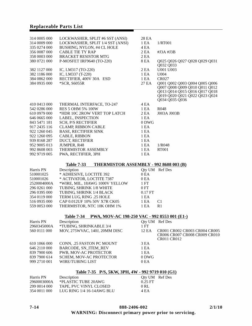
Replaceable Parts List
314 0005 000 LOCKWASHER, SPLIT #6 SST (ANSI) 28 EA314 0009 000 LOCKWASHER, SPLIT 1/4 SST (ANSI) 1 EA 1/RT001335 0274 000 BUSHING, NYLON, #4 CL HOLE 4 EA356 0087 000 CABLE TIE TY RAP 2 EA #J3A #J3B358 0003 000 BRACKET RESISTOR MTG 2 EA380 0721 000 P-MOSFET IRF9640 (TO-220) 8 EA Q025 Q026 Q027 Q028 Q029 Q031
Q032 Q033382 1127 000 IC, LM317 (TO-220) 2 EA U001 U003382 1186 000 IC, LM337 (T-220) 1 EA U004384 0862 000 RECTIFIER, 400V 30A ESD 1 EA CR027384 0935 000 *SCR, S6055R 27 EA Q001 Q002 Q003 Q004 Q005 Q006
Q007 Q008 Q009 Q010 Q011 Q012 Q013 Q014 Q015 Q016 Q017 Q018 Q019 Q020 Q021 Q022 Q023 Q024 Q034 Q035 Q036
410 0413 000 THERMAL INTERFACE, TO-247 4 EA542 0286 000 RES 5 OHM 5% 100W 1 EA R048610 0979 000 *HDR 10C 2ROW VERT TOP LATCH 2 EA J003A J003B646 0665 000 LABEL, INSPECTION 1 EA843 5471 181 SCH, P/S RECTIFIER 0 DWG917 2435 116 CLAMP, RIBBON CABLE 1 EA922 1260 045 BASE, RECTIFIER SINK 1 EA922 1260 095 CABLE, RIBBON 1 EA939 8168 287 DUCT, RECTIFIER 1 EA952 9005 013 JUMPER, R48 1 EA 1/R048992 8608 003 THERMISTOR ASSEMBLY 1 EA RT001992 9719 005 PWA, RECTIFIER, 3PH 1 EA
Table 7-33 THERMISTOR ASSEMBLY - 992 8608 003 (B)Harris PN Description Qty UM Ref Des510001025 * ADHESIVE, LOCTITE 392 0 EA510001026 * ACTIVATOR, LOCTITE 7387 0 EA2520004000A *WIRE, MIL, 18AWG 1000V YELLOW 1 FT296 0261 000 TUBING, SHRINK 1/8 WHITE 0 FT296 0395 000 TUBING, SHRINK 1/4 BLACK 0.17 FT354 0119 000 TERM LUG, RING .25 HOLE 1 EA516 0935 000 CAP 0.012UF 10% 50V X7R CK05 1 EA C1559 0053 000 THERMISTOR, NTC 10K OHM 1% 1 EA R1
Table 7-34 PWA, MOV-AC 198-250 VAC - 992 8553 001 (E1-)Harris PN Description Qty UM Ref Des2960345000A *TUBING, SHRINKABLE 3/4 1 FT560 0111 000 MOV, 275WVAC, 140J, 20MM DISC 12 EA CR001 CR002 CR003 CR004 CR005
CR006 CR007 CR008 CR009 CR010 CR011 CR012
610 1066 000 CONN, .25 FASTON PC MOUNT 3 EA646 2110 000 BARCODE, SN_ITEM_REV 1 EA839 7900 606 PWB, MOV-AC PROTECTOR 1 EA839 7900 614 SCHEM, MOV-AC PROTECTOR 0 DWG999 2710 001 WIRE/TUBING LIST 0 EA
Table 7-35 P/S, 5KW, 3PH, 4W - 992 9719 010 (G1)Harris PN Description Qty UM Ref Des2960003000A *PLASTIC TUBE 20AWG 0.25 FT299 0014 000 TAPE, PVC VINYL CLOSED 0 RL354 0011 000 LUG RING 1/4 16-14AWG BLU 4 EA
7-14 888-2406-002 2/1/10 WARNING: Disconnect primary power prior to servicing.

Replaceable Parts List
358 0293 000 PLUG, BUTTON 1/2 HOLE 1 EA358 3000 000 PLATE, END STOP, DIN RAIL MT 2 EA358 3793 000 BOLT, SHOULDER AXLE 4 EA448 1064 000 CASTER, WHEEL ONLY 4 EA472 1750 000 XFMR, 3PHASE, 240V PRI 2 EA A17T1 A17T2476 0427 000 CHOKE, POWER SUPPLY, 750UH,50A 4 EA A17L1 A17L2 A17L3 A17L4506 0300 000 CAP 20UF 440VAC 10% 3 EA A17C9 A17C10 A17C11524 0355 000 CAP 120,000 UF 60 VDC -10, +75 2 EA A17C1 A17C2540 1600 305 RES 1.5K OHM 3W 5% 2 EA A17R1 A17R2614 0808 000 *TERM BLK, 2C MODULAR 283 8 EA A17TB1614 0810 000 JUMPER, 2-POLE ADJACENT 283 3 EA646 1426 000 END PLATE 283 FRONT ENTRY 1 EA813 5611 137 STUD 4 EA817 1594 022 ROD, FILAMENT 2 EA C3 C4822 1004 001 BLOCKER FILAMENT 4 EA C3 C4829 9728 034 PLATE, FILAMENT FEEDTHRU 4 EA C3 C4917 2435 130 CABLE, PWR SUPPLY 2KW 1 EA917 2435 131 CABLE, 5KW PWR SUPPLY UPGRADE 1 EA917 2435 224 LABEL, PS OUTLINE, 3 PH, 5KW 1 EA922 1260 114 BRACKET, WAGO 1 EA939 8168 285 BRACKET, LOWER CHOKE MTG. 1 EA939 8168 286 BRACKET, UPPER CHOKE MTG. 1 EA943 5467 206 ANGLE, PS CHASSIS 4 EA943 5467 209 CHASSIS, PS, 3 PHASE 1 EA943 5467 211 GUIDE ROLLER, PS CHASSIS 2 EA943 5467 233 CAP/WAGO BRACKET 1 EA992 9719 006 ASSEMBLY, RECTIFIER, 3PH 2 EA A17A1 A17A2999 2883 001 HARDWARE LIST, P/S, 3PH, 3WIRE 1 EA358 3134 000 STUD, 1/4-20 X 1-3/4 BRASS 1 EA358 3343 000 LUG, 8 SOL TO 4 STR 1 EA917 2435 060 STANDOFF, AC DIST 4-WIRE 1 EA992 8553 003 PWA, MOV-AC 342-432 VAC 1 EA A18
Table 7-36 PWA, MOV-AC 342-432 VAC - 992 8553 003 (B1-)Harris PN Description Qty UM Ref Des2960345000A *TUBING, SHRINKABLE 3/4 1.375 FT560 0042 000 MOV, 510WVAC, 190J, 20MM DISC 6 EA RV001 RV002 RV003 RV004 RV005
RV006560 0049 000 *MOV, 275WVAC, 75J, 14MM DISC 14 EA RV007 RV008 RV009 RV010 RV011
RV012 RV013 RV014 RV015 RV016 RV017 RV018 RV019 RV020
610 1066 000 CONN, .25 FASTON PC MOUNT 4 EA646 2110 000 BARCODE, SN_ITEM_REV 1 EA839 8115 031 SCH, MOV-AC PROTECTOR 0 DWG839 8115 033 PWB, MOV-AC PROTECTOR, 1 EA999 2711 002 WIRE/TUBING LIST 0 EA
Table 7-37 P/S, 2.5KW, 3PH, 3W - 992 9719 011 (H)Harris PN Description Qty UM Ref Des2960003000A *PLASTIC TUBE 20AWG 0.125 FT299 0014 000 TAPE, PVC VINYL CLOSED 0 RL354 0011 000 LUG RING 1/4 16-14AWG BLU 2 EA358 3000 000 PLATE, END STOP, DIN RAIL MT 2 EA358 3793 000 BOLT, SHOULDER AXLE 4 EA398 0760 020 FUSE, CART 0.25X1.25 20A SLOW 1 EA F002402 0203 000 FUSEHOLDER 3AG SHOCKSAFE 1 EA
2/1/10 888-2406-002 7-15 WARNING: Disconnect primary power prior to servicing.

Replaceable Parts List
448 1064 000 CASTER, WHEEL ONLY 4 EA472 1750 000 XFMR, 3PHASE, 240V PRI 1 EA A17T1476 0427 000 CHOKE, POWER SUPPLY, 750UH,50A 2 EA A17L1 A17L2506 0299 000 CAP 25UF 330VAC 10% 3 EA A17C9 A17C10 A17C11524 0355 000 CAP 120,000 UF 60 VDC -10, +75 1 EA A17C1540 1600 305 RES 1.5K OHM 3W 5% 1 EA A17R1614 0808 000 *TERM BLK, 2C MODULAR 283 5 EA A17TB1646 1426 000 END PLATE 283 FRONT ENTRY 1 EA813 5611 137 STUD 2 EA817 1594 022 ROD, FILAMENT 1 EA822 1004 001 BLOCKER, FILAMENT 2 EA829 9728 034 PLATE, FILAMENT FEEDTHRU 2 EA917 2435 130 CABLE, PWR SUPPLY 2KW 1 EA917 2435 224 LABEL, PS OUTLINE, 3 PH, 5KW 1 EA922 1260 114 BRACKET, WAGO 1 EA939 8168 285 BRACKET, LOWER CHOKE MTG. 1 EA939 8168 286 BRACKET, UPPER CHOKE MTG. 1 EA943 5467 206 ANGLE, PS CHASSIS 4 EA943 5467 209 CHASSIS, PS, 3 PHASE 1 EA943 5467 211 GUIDE ROLLER, PS CHASSIS 2 EA943 5467 233 CAP/WAGO BRACKET 1 EA952 9005 012 JUMPER, WIRE 80, P/S 2.5KW 1 EA992 9719 006 ASSEMBLY, RECTIFIER, 3PH 1 EA A17A1999 2897 002 HARDWARE LIST, P/S 2KW 3PH 1 EA992 8553 001 PWA, MOV-AC 198-250 VAC 1 EA A18
Table 7-38 P/S, 2.5KW, 3PH, 4W - 992 9719 012 (H)Harris PN Description Qty UM Ref Des2960003000A *PLASTIC TUBE 20AWG 0.125 FT299 0014 000 TAPE, PVC VINYL CLOSED 0 RL354 0011 000 LUG RING 1/4 16-14AWG BLU 2 EA358 0293 000 PLUG, BUTTON 1/2 HOLE 1 EA358 3000 000 PLATE, END STOP, DIN RAIL MT 2 EA358 3793 000 BOLT, SHOULDER AXLE 4 EA448 1064 000 CASTER, WHEEL ONLY 4 EA472 1750 000 XFMR, 3PHASE, 240V PRI 1 EA A17T1476 0427 000 CHOKE, POWER SUPPLY, 750UH,50A 2 EA A17L1 A17L2506 0300 000 CAP 20UF 440VAC 10% 3 EA A17C9 A17C10 A17C11524 0355 000 CAP 120,000 UF 60 VDC -10, +75 1 EA A17C1540 1600 305 RES 1.5K OHM 3W 5% 1 EA A17R1614 0808 000 *TERM BLK, 2C MODULAR 283 5 EA A17TB1646 1426 000 END PLATE 283 FRONT ENTRY 1 EA813 5611 137 STUD 2 EA817 1594 022 ROD, FILAMENT 1 EA822 1004 001 BLOCKER, FILAMENT 2 EA829 9728 034 PLATE, FILAMENT FEEDTHRU 2 EA917 2435 130 CABLE, PWR SUPPLY 2KW 1 EA917 2435 224 LABEL, PS OUTLINE, 3 PH, 5KW 1 EA922 1260 114 BRACKET, WAGO 1 EA939 8168 285 BRACKET, LOWER CHOKE MTG. 1 EA939 8168 286 BRACKET, UPPER CHOKE MTG. 1 EA943 5467 206 ANGLE, PS CHASSIS 4 EA943 5467 209 CHASSIS, PS, 3 PHASE 1 EA943 5467 211 GUIDE ROLLER, PS CHASSIS 2 EA943 5467 233 CAP/WAGO BRACKET 1 EA952 9005 012 JUMPER, WIRE 80, P/S 2.5KW 1 EA
7-16 888-2406-002 2/1/10 WARNING: Disconnect primary power prior to servicing.

Replaceable Parts List
992 9719 006 ASSEMBLY, RECTIFIER, 3PH 1 EA A17A1999 2898 002 HARDWARE LIST, P/S 2KW 4-WIRE 1 EA358 3134 000 STUD, 1/4-20 X 1-3/4 BRASS 1 EA358 3343 000 LUG, 8 SOL TO 4 STR 1 EA917 2435 060 STANDOFF, AC DIST 4-WIRE 1 EA992 8553 003 PWA, MOV-AC 342-432 VAC 1 EA A18
Table 7-39 P/S, 1PH, Z5, Z3.5, & Z2R - 992 9719 023 (C)Harris PN Description Qty UM Ref Des398 0760 020 FUSE, CART 0.25X1.25 20A SLOW 1 EA F002402 0203 000 FUSEHOLDER 3AG SHOCKSAFE 1 EA817 1594 022 ROD, FILAMENT 2 EA822 1004 001 BLOCKER, FILAMENT 4 EA829 9728 034 PLATE, FILAMENT FEEDTHRU 4 EA992 8553 001 PWA, MOV-AC 198-250 VAC 1 EA A18992 9719 013 P/S, 5KW, 1PH 1 EA
Table 7-40 P/S, 5KW, 1PH - 992 9719 013 (K)Harris PN Description Qty UM Ref Des2520006000A *WIRE, MIL, 14AWG 1000V BLUE 2.5 FT2960003000A *PLASTIC TUBE 20AWG 0.25 FT296 0262 000 TUBING, SHRINK 1/4 WHITE 0.5 FT354 0008 000 LUG RING #6 16-14AWG BLU 2 EA354 0011 000 LUG RING 1/4 16-14AWG BLU 4 EA354 0252 000 LUG QC FEM 250 16-14AWG BLU 2 EA358 0003 000 BRACKET RESISTOR MTG 4 EA358 3000 000 PLATE, END STOP, DIN RAIL MT 2 EA358 3466 000 FLANGE, GREY (264) 1 EA358 3793 000 BOLT, SHOULDER AXLE 4 EA384 0767 000 SCR, 1000PIV 150A 150C100 16 EA A17A1CR1 A17A1CR2 A17A1CR3
A17A1CR4 A17A1CR5 A17A1CR6 A17A1CR7 A17A1CR8 A17A2CR1 A17A2CR2 A17A2CR3 A17A2CR4 A17A2CR5 A17A2CR6 A17A2CR7 A17A2CR8
398 0526 000 FUSE, LIMITER TYPE, 100A 125V 16 EA A17A1F1 A17A1F2 A17A1F3 A17A1F4 A17A1F5 A17A1F6 A17A1F7 A17A1F8 A17A2F1 A17A2F2 A17A2F3 A17A2F4 A17A2F5 A17A2F6 A17A2F7 A17A2F8
448 1064 000 CASTER, WHEEL ONLY 4 EA472 1761 000 TRANSFORMER, 1 PHASE 2 EA A17A1T1 A17A2T2476 0428 000 CHOKE, PWR SUP, 1.5MH 100A 2 EA A17A1L1 A17A2L2506 0287 000 CAP 45UF 330VAC 50/60HZ 2 EA A17C9 A17C10524 0355 000 CAP 120,000 UF 60 VDC -10, +75 6 EA A17A1C1 A17A1C5 A17A1C15
A17A2C2 A17A2C6 A17A2C16540 1600 305 RES 1.5K OHM 3W 5% 2 EA A17A1R1 A17A2R2542 0286 000 RES 5 OHM 5% 100W 2 EA612 1451 000 PLUG, FEMALE 4C 1ROW STRAIGHT 8 EA614 0808 000 *TERM BLK, 2C MODULAR 283 6 EA A17TB1614 0810 000 JUMPER, 2-POLE ADJACENT 283 2 EA614 0885 000 TERM BLK, THRU, 4-POLE, BLUE (264) 1 EA646 1426 000 END PLATE 283 FRONT ENTRY 1 EA813 5611 137 STUD 12 EA917 2435 061 SPACER, FUSE PLATE 8 EA917 2435 223 LABEL, PS OUTLINE, 1PH 1 EA
2/1/10 888-2406-002 7-17 WARNING: Disconnect primary power prior to servicing.

Replaceable Parts List
917 2435 954 CABLE, 5KW,1PH, PS 1 EA922 1195 010 RAIL TERM BLOCK MTG 1 EA922 1260 071 ASSY, RECTIFIER HEATSINK 2 EA922 1260 072 PLATE, FUSE MTG. 2 EA922 1260 228 STRAP CONNECTION CAP 2 EA939 8168 291 CLAMP, CAPACITOR 2 EA939 8168 292 PLATE, RECTIFIER MTG. 2 EA943 5467 206 ANGLE, PS CHASSIS 4 EA943 5467 210 CHASSIS, PS, 1 PHASE 1 EA943 5467 211 GUIDE ROLLER, PS CHASSIS 2 EA952 9005 013 JUMPER, R48 2 EA992 9762 001 PWA, P/S RECTIFIER, 1 PH 2 EA A17A1A1 A17A2A1
Table 7-41 PWA, P/S RECTIFIER, 1 PH - 992 9762 001 (V)Harris PN Description Qty UM Ref Des860001004 SEALANT, HIGH STRENGTH 0 EA300 1578 000 SCREW, PHMS 10-32 X 5/8 BRASS 1 EA302 0780 000 SCREW, PHMS, 6-32 X 3/8 10 EA304 0098 000 NUT, HEX 10-32 SMALL PATTERN 2 EA308 0007 000 WASHER, FLAT #10 BRASS (ANSI REGULAR)2 EA312 0007 000 WASHER, INT LOCK 10 1 EA312 0049 000 LOCKWASHER, SPLIT #10 PH-BRZ (ANSI) 1 EA357 0037 000 SCREW 6-32 X .25 BHMS 8 EA XQ006 XQ007 XQ012 XQ013 XU001
XU003 XU004358 1928 000 JUMPER 1/4 LG 1/8H 1 EA JP004380 0190 000 *XSTR, PNP, MMBT3906 1 EA Q009380 0721 000 P-MOSFET IRF9640 (TO-220) 10 EA Q001 Q002 Q003 Q004 Q005 Q006
Q007 Q008 Q012 Q013382 1127 000 IC, LM317 (TO-220) 2 EA U001,U003382 1186 000 IC, LM337 (T-220) 1 EA U004382 1502 000 IC, L603C, 8 DRIVER, ESD 1 EA U002384 0253 000 DIODE, RECT 1N4007 11 EA CR001 CR002 CR003 CR004 CR006
CR007 CR008 CR009 CR028 CR029 CR031
384 0341 000 DIODE, RECT 1N5404 4 EA CR005 CR010 CR025 CR032384 0862 000 RECTIFIER, 400V 30A ESD 1 EA CR027384 0935 000 *SCR, S6055R 2 EA Q010,Q011386 0082 000 *ZENER 1N4744A 15V 5% 1W 1 EA CR026398 0140 000 FUSE, FAST CART 15A 250V 2 EA F001,F002402 0199 000 CLIP, 1/4 DIA FUSE 4 EA404 0766 000 SOCKET, DIP, 18 PIN (DL) 1 EA XU002410 0405 000 THERMAL INTERFACE, TO220 7 EA XQ004 XQ006 XQ007 XQ012 XQ013
XU001 XU003410 0413 000 THERMAL INTERFACE, TO-247 1 EA516 0453 000 CAP 0.100UF 10% 100V X7R 23 EA C002 C003 C004 C005 C006 C007
C008 C009 C025 C032 C033 C034 C035 C036 C037 C040 C041 C043 C044 C045 C046 C047 C048
516 0530 000 CAP 0.010UF 10% 100V X7R 1 EA C013516 0736 000 CAP 1000PF 10% 100V X7R 2 EA C010 C011516 0813 000 NTWK, CAP .01UF 50V 20% SIP 1 EA C027516 0825 000 CAP 3300PF 10% 100V X7R CK05 1 EA C001522 0555 000 *CAP 100UF 50V 20% (8X11.5) 3 EA C029 C030 C039522 0574 000 CAP 22UF 50V 20% 1 EA C028522 0576 000 CAP 1,000UF 50V 20% 1 EA C012522 0590 000 CAP 470UF 25V 20% 3 EA C031 C049 C050540 1380 000 RES NETWORK 10K OHM 2% 1 EA R001
7-18 888-2406-002 2/1/10 WARNING: Disconnect primary power prior to servicing.

Replaceable Parts List
540 1461 000 RES NETWORK 100 OHM 2% 1 EA R002540 1600 204 RES 130 OHM 3W 5% 8 EA R015 R016 R017 R019 R021 R022
R023 R024540 1600 212 RES 300 OHM 3W 5% 1 EA R018548 2400 130 RES 20 OHM 1/2W 1% 1 EA R060548 2400 201 RES 100 OHM 1/2W 1% 15 EA R003 R004 R005 R006 R011 R012
R013 R014 R025 R026 R027 R028 R046 R051 R064
548 2400 209 RES 121 OHM 1/2W 1% 3 EA R042 R056 R058548 2400 278 RES 634 OHM 1/2W 1% 1 EA R043548 2400 328 RES 1.91K OHM 1/2W 1% 2 EA R057 R059548 2400 334 RES 2.21K OHM 1/2W 1% 1 EA R020548 2400 401 RES 10K OHM 1/2W 1% 6 EA R047 R053 R054 R055 R061 R063548 2400 430 RES 20K OHM 1/2W 1% 1 EA R062548 2400 488 RES 80.6K OHM 1/2W 1% 2 EA R007 R008548 2400 501 RES 100K OHM 1/2W 1% 1 EA R050548 2400 530 RES 200K OHM 1/2W 1% 2 EA R009 R010560 0121 011 POSISTOR 1.1 AMP 60VDC 13MM DISC 1 EA F003610 0877 000 HDR, 2C VERT 1ROW UNSHR 4 EA JP001 JP002 JP003 JP005610 0982 000 *HDR 26C 2ROW VERT TOP LATCH 1 EA J004610 1066 000 CONN, .25 FASTON PC MOUNT 1 EA E003610 1106 000 HDR, 8C VERT 1ROW FRICTION 3 EA J005 J006 J007610 1235 000 HDR, MALE 4C 1ROW VERTICAL 1 EA J008610 1236 000 HDR, MALE 8C 1ROW VERTICAL 3 EA J001 J002 J003612 1184 000 JUMPER SHUNT, 2C, 0.1’’ PITCH 4 EA646 0665 000 LABEL, INSPECTION 1 EA646 2110 000 BARCODE, SN_ITEM_REV 1 EA843 5471 251 SCH, P/S RECTIFIER, 1PH 0 DWG843 5471 253 PWB, P/S RECTIFIER, 1PH 1 EA939 8168 120 HEATSINK, 1PH RECTIFIER 1 EA943 5467 131 CHASSIS, 1PH RECTIFIER 1 EA992 8608 004 THERMISTOR ASSEMBLY 1 EA RT001
Table 7-42 THERMISTOR ASSEMBLY - 992 8608 004 (B)Harris PN Description Qty UM Ref Des510001025 * ADHESIVE, LOCTITE 392 0 EA510001026 * ACTIVATOR, LOCTITE 7387 0 EA2520004000A *WIRE, MIL, 18AWG 1000V YELLOW 1.5 FT296 0261 000 TUBING, SHRINK 1/8 WHITE 0 FT296 0395 000 TUBING, SHRINK 1/4 BLACK 0.17 FT354 0119 000 TERM LUG, RING .25 HOLE 1 EA516 0935 000 CAP 0.012UF 10% 50V X7R CK05 1 EA C1559 0053 000 THERMISTOR, NTC 10K OHM 1% 1 EA R1
Table 7-43 P/S, 1PH, Z2 (NON-REDUNDANT) - 992 9719 024 (C)Harris PN Description Qty UM Ref Des398 0760 020 FUSE, CART 0.25X1.25 20A SLOW 1 EA F002402 0203 000 FUSEHOLDER 3AG SHOCKSAFE 1 EA817 1594 022 ROD, FILAMENT 1 EA822 1004 001 BLOCKER, FILAMENT 2 EA829 9728 034 PLATE, FILAMENT FEEDTHRU 2 EA992 8553 001 PWA, MOV-AC 198-250 VAC 1 EA A18992 9719 014 P/S, 2.5KW, 1 PH 1 EA
Table 7-44 P/S, 2.5KW, 1 PH - 992 9719 014 (L)Harris PN Description Qty UM Ref Des
2/1/10 888-2406-002 7-19 WARNING: Disconnect primary power prior to servicing.

Replaceable Parts List
266010003 GROMMET STRIP, 0.125 5.5 FT358 0003 000 BRACKET RESISTOR MTG 2 EA R048358 3000 000 PLATE, END STOP, DIN RAIL MT 2 EA358 3466 000 FLANGE, GREY (264) 1 EA358 3793 000 BOLT, SHOULDER AXLE 4 EA384 0767 000 SCR, 1000PIV 150A 150C100 8 EA A17A1CR1 A17A1CR2 A17A1CR3
A17A1CR4 A17A1CR5 A17A1CR6 A17A1CR7 A17A1CR8
398 0526 000 FUSE, LIMITER TYPE, 100A 125V 8 EA A17A1F1 A17A1F2 A17A1F3 A17A1F4 A17A1F5 A17A1F6 A17A1F7 A17A1F8
448 1064 000 CASTER, WHEEL ONLY 4 EA472 1761 000 TRANSFORMER, 1 PHASE 1 EA A17A1T1476 0428 000 CHOKE, PWR SUP, 1.5MH 100A 1 EA A17A1L1506 0287 000 CAP 45UF 330VAC 50/60HZ 2 EA A17A1C9 A17A1C10524 0355 000 CAP 120,000 UF 60 VDC -10, +75 3 EA A17A1C1 A17A1C5 A17A1C15530 0092 000 BRACKET, CAP, 3 ID 3 EA540 1600 305 RES 1.5K OHM 3W 5% 1 EA A17A1R1542 0286 000 RES 5 OHM 5% 100W 1 EA R048612 1451 000 PLUG, FEMALE 4C 1ROW STRAIGHT 4 EA614 0808 000 *TERM BLK, 2C MODULAR 283 6 EA A17TB1614 0810 000 JUMPER, 2-POLE ADJACENT 283 2 EA614 0885 000 TERM BLK, THRU, 4-POLE, BLUE (264) 1 EA646 1426 000 END PLATE 283 FRONT ENTRY 1 EA813 5611 137 STUD 6 EA917 2435 061 SPACER, FUSE PLATE 4 EA917 2435 095 STRAP, CAPACITOR CONNECTION 1 EA917 2435 096 STRAP, CAPACITOR CONNECTION 1 EA917 2435 147 CABLE, 2KW 1PH 1 EA917 2435 223 LABEL, PS OUTLINE, 1PH 1 EA922 1195 010 RAIL TERM BLOCK MTG 1 EA922 1260 071 ASSY, RECTIFIER HEATSINK 1 EA922 1260 072 PLATE, FUSE MTG. 1 EA922 1260 114 BRACKET, WAGO 1 EA922 1260 153 BRACKET, WAGO, 1PH P/S 1 EA922 1260 228 STRAP CONNECTION CAP 1 EA939 8168 078 TOP PLATE, P/S CHASSIS 1 EA939 8168 079 PLATE, HEATSINK MTG. 1 EA939 8168 081 CHASSIS, HEATSINK/CAPACITOR 1 EA939 8168 121 PLATE, RECTIFIER MTG. 1 EA939 8168 291 CLAMP, CAPACITOR 1 EA939 8168 292 PLATE, RECTIFIER MTG. 1 EA943 5467 206 ANGLE, PS CHASSIS 4 EA943 5467 210 CHASSIS, PS, 1 PHASE 1 EA943 5467 211 GUIDE ROLLER, PS CHASSIS 2 EA952 9005 013 JUMPER, R48 2 EA992 9762 001 PWA, P/S RECTIFIER, 1 PH 1 EA A17A1A1
7-20 888-2406-002 2/1/10 WARNING: Disconnect primary power prior to servicing.