Embed Size (px)
Citation preview
8/20/2019 Flywheel Nice Material
http://slidepdf.com/reader/full/flywheel-nice-material 1/21
115
Flywheel
UNIT 4 FLYWHEEL
Structure
4.1 Introduction
Objectives
4.2 Dynamically Equivalent System
4.3 Turning Moment Diagram
4.3.1 Turning Moment Diagram of a Single Cylinder 4-storke IC Engine
4.3.2 Turning Moment Diagram of a Multicylinder 4-stroke IC Engine
4.3.3 Turning Moment Diagram of a Single Cylinder Double Acting Steam Engine
4.4 Fluctuation of Energy and Speed
4.5 Flywheel Design
4.5.1 Mass Moment of Inertia of Flywheel for an IC Engine
4.5.2 Mass Moment of Inertia of Flywheel for a Punching Press
4.5.3 Design of Flywheel
4.6 Summary
4.7 Key Words
4.8 Answers to SAQs
4.1 INTRODUCTION
In practice, there are two following types of cases where reciprocating engine
mechanism is used :
(a) An internal combustion engine or a steam engine which is used as a prime
mover to drive generators, centrifugal pumps, etc.
(b) A punching machine which is driven by a prime mover like electric motor.
In both these cases either a variable torque is supplied where demand is a constant torque
or demand is variable torque whereas constant torque is supplied. In both these cases
there is mismatch between the supply and demand. This results in speed variation. In
case of generators, speed variation results in change in frequency and variation in
voltage. On the other hand, punching machine requires energy at small interval only
when punching is done. To supply such large energy at the time of punching, motor of
high power shall be required. At the same time, there will be large variation in speed. To
smoothen these variations in torque, flywheel is used which works as a energy storage.
This results in usage of low power motor in punching machine.
Objectives
After studying this unit, you should be able to
explain the method of drawing turning moment diagram for a prime mover,
determine the fluctuation of energy in a cycle,
determine the power of prime power, and
determine mass moment of inertia of a flywheel and design it.
4.2 DYNAMICALLY EQUIVALENT SYSTEM
The slider-crank mechanism is one of the most commonly used mechanism. It is used in
prime movers, reciprocating compressors, punching machine, press, etc. The
reciprocating mass comprises mass of the piston and part of the mass of the connecting
8/20/2019 Flywheel Nice Material
http://slidepdf.com/reader/full/flywheel-nice-material 2/21
116
Theory of Machines rod. One end of the connecting rod reciprocates with piston and other end rotates with
crank. We want to replace this link by a mass less link which is dynamically equivalent
by having two point masses m1, at the piston end and m2 at the crank end.
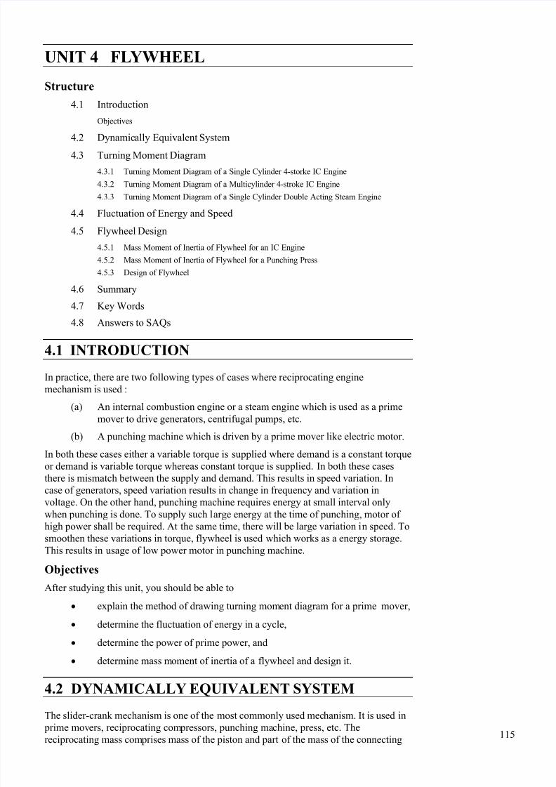
In a general case, we can think of a rigid link of any shape as shown in Figure 4.1. Let
this be subjected to a system of forces whose resultant is say ‘ F ’ generating a couple
Fe about centre of gravity G. This force produces linear acceleration ‘a’ F
m
and
angular acceleration ‘’ F e
I
, where I is mass moment of inertia about a
perpendicular axis through G.
Figure 4.1 : Dynamically Equivalent System
For the massless link having point masses m1 and m2 to be dynamically equivalent, it
should generate same accelerations ‘a’ and ‘’ due to the action of same force ‘ F ’.
Let a1 and a2 be the distances of the point masses m1 and m2 from centre of gravity G,
respectively.
For a dynamically equivalent system having accelerations ‘a’ and ‘’.
(a) Total mass should be same, i.e.
1 2m m m . . . (4.1)
(b) Position of centre of gravity should remain same, i.e.
1 1 2 2m a m a . . . (4.2)
(c) Mass moment of inertia should be same, i.e.
2 21 1 2 2m a m a I . . . (4.3)
These three Eqs. (4.1) to (4.3) should be satisfied for complete dynamical equivalence.
There are four unknowns (m1, m2, a1 and a2) and the three equations. Therefore, one of
these four variables can be arbitrarily assumed and other three can be determined to
provide a unique solution.
For slider-crank mechanism, it will be convenient to have mass m1 with the piston and
mass m2 at the crank end and thus a1 and a2 are selected before hand. But in that case all
the three equations cannot be satisfied.
From Eqs. (4.1) to (4.3),
21
1 2( )
am m
a a
and 1
21 2( )
a mm
a a
and mass moment of inertia = m a1 a2.
If masses m1 and m2 are located at above mentioned positions the Eq. (4.3) shall not be
satisfied. The change in moment of inertia will be
1 2 I m a a
2 21 2 1 2( )m k m a a m k a a
a1 a2
m1 m2
F
G
G
e
8/20/2019 Flywheel Nice Material
http://slidepdf.com/reader/full/flywheel-nice-material 3/21
117
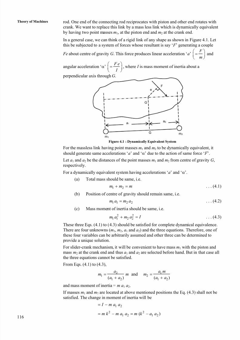
FlywheelThe correction couple has to be determined and it will be 2
1 2( )m k a a . This couple
can be thought of applied by the two forces F C as shown in Figure 4.2.
Figure 4.2 : Slider Crank Mechanism
Therefore, 21 2cos ( )C F l m k a a
or,2
1 2( )
cosC
m k a a F
l
. . . (4.4)
The correction in the turning moment will be equal to the moment of force F C shown by
the dashed line about the crank centre.
Correction couple2
1 2( )cos cos
cosC
m k a a F r r
l
Let r
l
But
12 2
2
2cos 1 sin
r
l
1 2 42 2 2 42(1 sin ) 1 sin sin . . .
2 8
Differentiating it w.r.t. ‘t ’ and dividing it by sin = sin
32cos sin cos . . .
2
d
dt
Differentiating again w.r.t. ‘t ’ and assuming ‘’ constant
22
2
' '
( (sin ))
d
dt (By approximation neglecting higher terms)
or,2
2
2
' 'sin ' '
d l
r dt
Substituting for
Correction couple2 2 2
1 2( )' ' sin 2
cos 2c
m k a a r M
l l
. . . (11.5)
SAQ 1
What is the advantage of determining dynamically equivalent link for connectingrod?
F c
rO2
A
F c
G
B l
F c
m (k2 – a1 a2)
8/20/2019 Flywheel Nice Material
http://slidepdf.com/reader/full/flywheel-nice-material 4/21
118
Theory of Machines4.3 TURNING MOMENT DIAGRAM
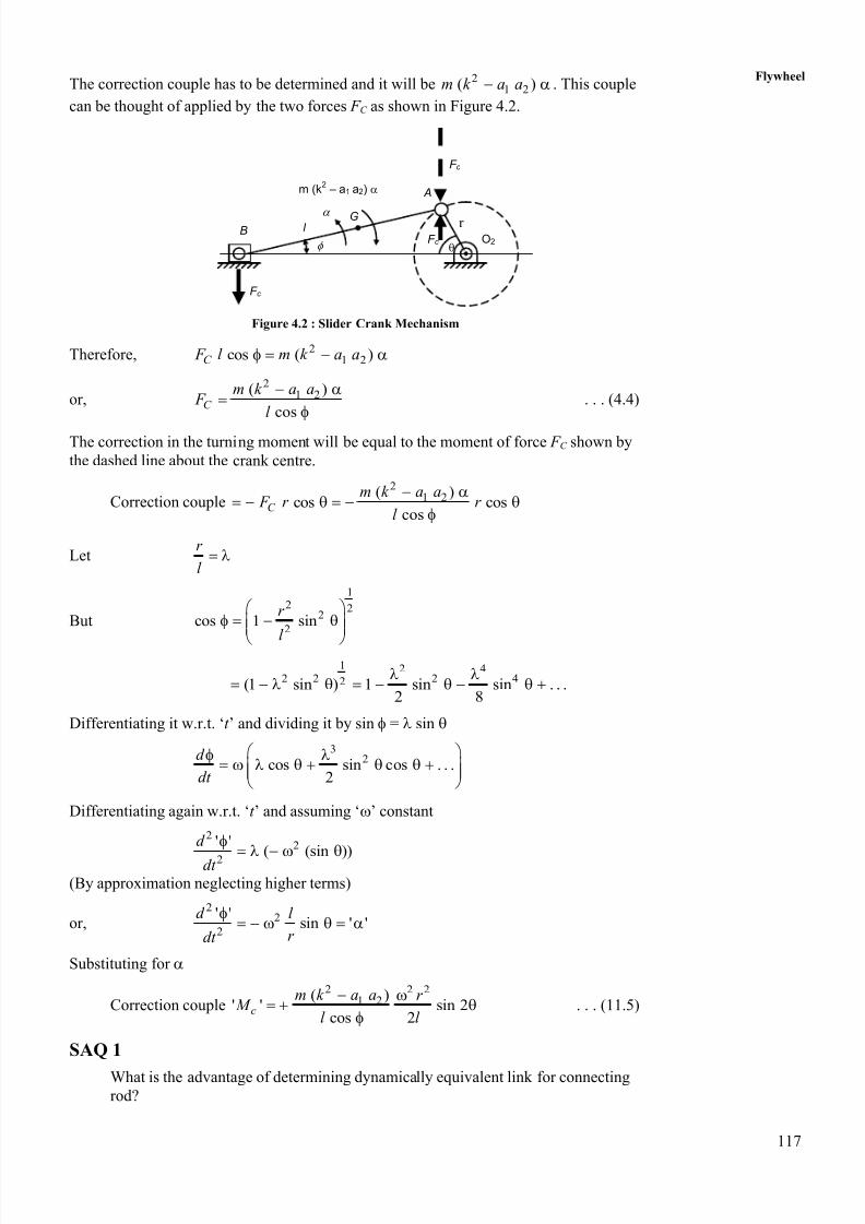
Figure 4.3 shows a layout of a horizontal engine.
Let p = effective gas pressure on the piston in N/m2,
A = area of the piston in m2,
mrec = mass of reciprocating parts, i.e. mass of the piston gudgeon pin and part of
mass of connecting rod ‘m1’,
Q = thrust force on the connecting rod in N,
= angular velocity of the crank, and
M = Turning moment on the crank.
(a)
(b) (c)Figure 4.3 : Turning Moment Diagram
cos recQ p A m x
2cos cos 2rec
r p A m r
l
or,
2 cos cos 2
cos
rec
r pA m r
l Q
2 sin ( )sin ( ) cos cos 2
cosrec
r r M Q r pA m r
l
2 (sin cos cos sin )cos cos 2
cosrec
r r pA m r
l
2cos cos 2 (sin cos tan )rec
r r pA m r
l
. . . (4.6)
or,
2
2cos cos 2rec
r
M pA m r O Dl
. . . (4.7)
In case of a vertical engine.
r
O2
B
l
N
(Gas Force)
Am2
P A
xmrec
P A
Q (Connecting Rod Thrust)
mrec x (inertia force)
N
GasForce
A
CD Q
O2
( + )
8/20/2019 Flywheel Nice Material
http://slidepdf.com/reader/full/flywheel-nice-material 5/21
119
Flywheel2
cos cos 2 (sin cos tan )rec rec
r M r pA m r m g
l
. . . (4.8)
22cos cos 2rec rec
r pA m r m g O D
l
. . . (4.9)
Considering the correction couple also, the actual turning moment is
t C M M M
4.3.1 Turning Moment Diagram of a Single Cylinder
4-stroke IC Engine
If the effect of correction couple is ignored, the approximate turning moment
M = (Gas force + Inertia force) O2 D
The diagram which is plotted for ‘ M ’ against crank angle ‘’ is called turning moment
diagram. This diagram can be plotted progressively as explained below :
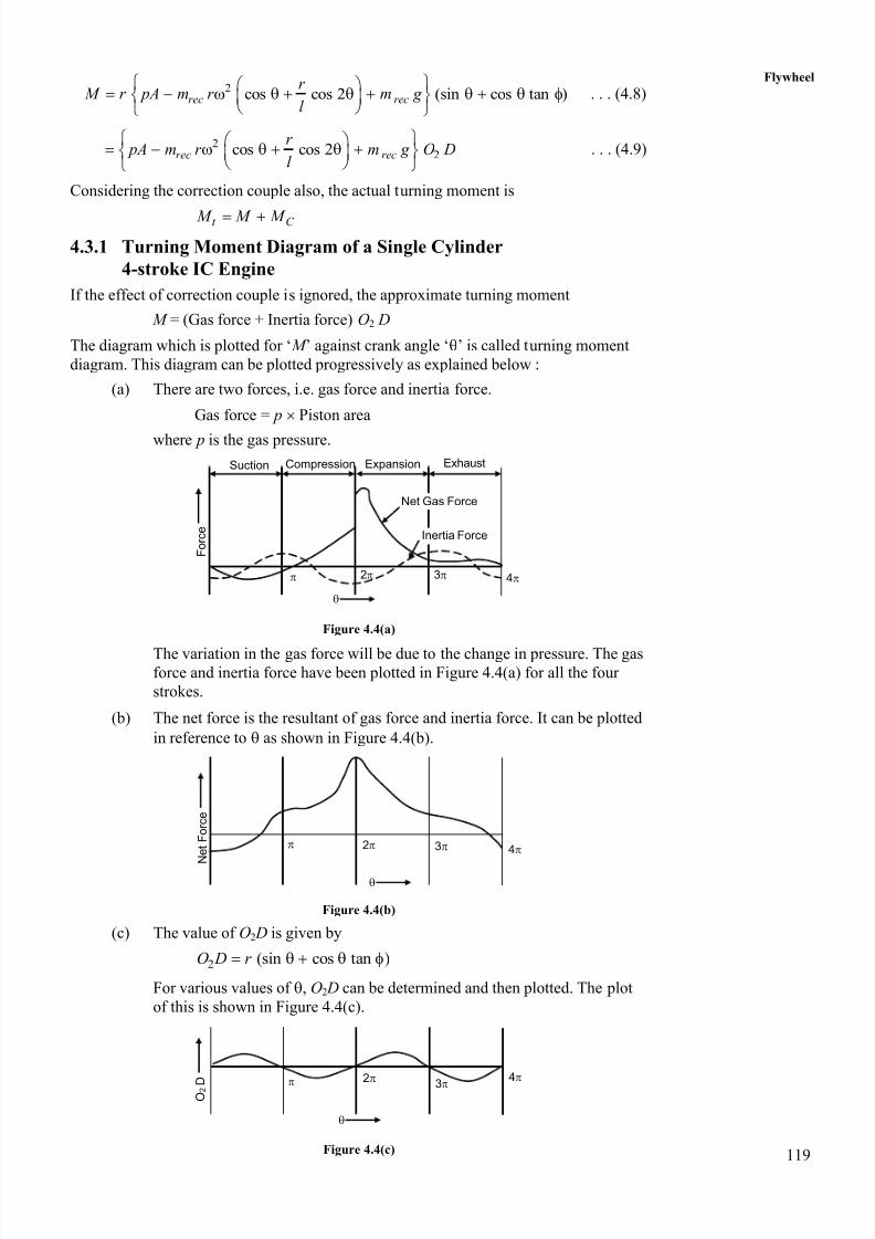
(a) There are two forces, i.e. gas force and inertia force.
Gas force = p Piston area
where p is the gas pressure.
Figure 4.4(a)
The variation in the gas force will be due to the change in pressure. The gasforce and inertia force have been plotted in Figure 4.4(a) for all the four
strokes.
(b) The net force is the resultant of gas force and inertia force. It can be plotted
in reference to as shown in Figure 4.4(b).
Figure 4.4(b)
(c) The value of O2 D is given by
2 (sin cos tan )O D r
For various values of , O2 D can be determined and then plotted. The plot
of this is shown in Figure 4.4(c).
Figure 4.4(c)
Suction Compression Expansion Exhaust
Net Gas Force
Inertia Force
2 3 4
F o r c e
2 3 4 N e t F o r c e
2
3 4
O 2 D
8/20/2019 Flywheel Nice Material
http://slidepdf.com/reader/full/flywheel-nice-material 6/21
120
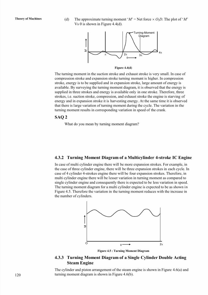
Theory of Machines (d) The approximate turning moment ‘ M ’ = Net force O2 D. The plot of ‘ M ’
Vs is shown in Figure 4.4(d).
Figure 4.4(d)
The turning moment in the suction stroke and exhaust stroke is very small. In case of
compression stroke and expansion stroke turning moment is higher. In compression
stroke, energy is to be supplied and in expansion stroke, large amount of energy is
available. By surveying the turning moment diagram, it is observed that the energy is
supplied in three strokes and energy is available only in one stroke. Therefore, three
strokes, i.e. suction stroke, compression, and exhaust stroke the engine is starving of
energy and in expansion stroke it is harvesting energy. At the same time it is observed
that there is large variation of turning moment during the cycle. The variation in the
turning moment results in corresponding variation in speed of the crank.
SAQ 2
What do you mean by turning moment diagram?
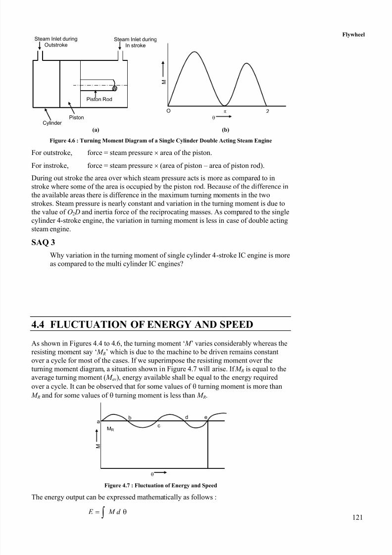
4.3.2 Turning Moment Diagram of a Multicylinder 4-stroke IC Engine
In case of multi cylinder engine there will be more expansion strokes. For example, in
the case of three cylinder engine, there will be three expansion strokes in each cycle. In
case of 4 cylinder 4-strokes engine there will be four expansion strokes. Therefore, in
multi cylinder engine there will be lesser variation in turning moment as compared to
single cylinder engine and consequently there is expected to be less variation in speed.
The turning moment diagram for a multi cylinder engine is expected to be as shown in
Figure 4.5. Therefore the variation in the turning moment reduces with the increase in
the number of cylinders.
Figure 4.5 : Turning Moment Diagram
4.3.3 Turning Moment Diagram of a Single Cylinder Double ActingSteam Engine
The cylinder and piston arrangement of the steam engine is shown in Figure 4.6(a) and
turning moment diagram is shown in Figure 4.6(b).
Turning-MomentDiagram
2 3 4
M
M
O 2
8/20/2019 Flywheel Nice Material
http://slidepdf.com/reader/full/flywheel-nice-material 7/21
121
Flywheel
(a) (b)
Figure 4.6 : Turning Moment Diagram of a Single Cylinder Double Acting Steam Engine
For outstroke, force = steam pressure area of the piston.
For instroke, force = steam pressure (area of piston – area of piston rod).
During out stroke the area over which steam pressure acts is more as compared to in
stroke where some of the area is occupied by the piston rod. Because of the difference in
the available areas there is difference in the maximum turning moments in the twostrokes. Steam pressure is nearly constant and variation in the turning moment is due to
the value of O2 D and inertia force of the reciprocating masses. As compared to the single
cylinder 4-stroke engine, the variation in turning moment is less in case of double acting
steam engine.
SAQ 3
Why variation in the turning moment of single cylinder 4-stroke IC engine is more
as compared to the multi cylinder IC engines?
4.4 FLUCTUATION OF ENERGY AND SPEED
As shown in Figures 4.4 to 4.6, the turning moment ‘ M ’ varies considerably whereas the
resisting moment say ‘ M R’ which is due to the machine to be driven remains constant
over a cycle for most of the cases. If we superimpose the resisting moment over the
turning moment diagram, a situation shown in Figure 4.7 will arise. If M R is equal to the
average turning moment ( M av), energy available shall be equal to the energy required
over a cycle. It can be observed that for some values of turning moment is more than M R and for some values of turning moment is less than M R.
Figure 4.7 : Fluctuation of Energy and Speed
The energy output can be expressed mathematically as follows :
E M d
Piston Rod
Steam Inlet duringOutstroke
Steam Inlet duringIn stroke
CylinderPiston
M
O 2
a b
c
d e
M
MR
8/20/2019 Flywheel Nice Material
http://slidepdf.com/reader/full/flywheel-nice-material 8/21
122
Theory of Machines The average turning moment for the cycle is
Angle for cycleav
E M
The angle for the cycle is 2 for the two stroke engines and 4 for four strokes engines
and in case of steam engines it is 2.
For a stable operation of the system
M R = M av
In the stable system, the mean speed remains constant but variation of speed will be
there within the cycle. The speed remains same at the beginning and at the end of the
cycle.
If M R < M av, the speed increases from cycle to cycle. The speed graph is shown in
Figure 4.8(a).
If M R > M av, the speed decreases from the cycle to the cycle. The speed graph is shown in
Figure 4.8(b).
(a) (b)
Figure 4.8 : Speed Graph
From Figure 4.7, we observe that M R = M av at points a, b, c, d and e. Since M > M R from
a to b, speed of the crank shaft will increase during this period. From b to c M < M R and
speed will decrease. Similar situation will occur for c to d and d to e. At e the cycle is
complete and the speed at e is same as that of a. The energy at all these points can be
determined.
( )
b
b a R
a
E E M M d
( )
c
c b R
b
E E M M d
( )
d
d c R
c
E E M M d
( )
e
e d R a
d
E E M M d E
Out of all these energies so determined, we can find minimum and maximum energies,the difference in these energy levels shall give maximum fluctuation of energy ( E )max
max max min( ) E E E
S p e e d
Time
MR Mav
MR Mav
S p e e d
Time
8/20/2019 Flywheel Nice Material
http://slidepdf.com/reader/full/flywheel-nice-material 9/21
123
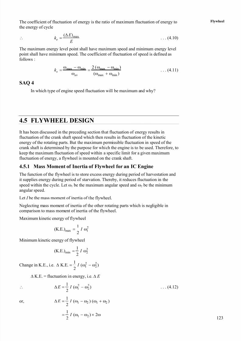
FlywheelThe coefficient of fluctuation of energy is the ratio of maximum fluctuation of energy to
the energy of cycle
max( )e
E k
E
. . . (4.10)
The maximum energy level point shall have maximum speed and minimum energy level
point shall have minimum speed. The coefficient of fluctuation of speed is defined as
follows :
max min max min
max min
2 ( )
( ) s
av
k
. . . (4.11)
SAQ 4
In which type of engine speed fluctuation will be maximum and why?
4.5 FLYWHEEL DESIGN
It has been discussed in the preceding section that fluctuation of energy results in
fluctuation of the crank shaft speed which then results in fluctuation of the kinetic
energy of the rotating parts. But the maximum permissible fluctuation in speed of the
crank shaft is determined by the purpose for which the engine is to be used. Therefore, to
keep the maximum fluctuation of speed within a specific limit for a given maximum
fluctuation of energy, a flywheel is mounted on the crank shaft.
4.5.1 Mass Moment of Inertia of Flywheel for an IC Engine
The function of the flywheel is to store excess energy during period of harvestation and
it supplies energy during period of starvation. Thereby, it reduces fluctuation in thespeed within the cycle. Let 1 be the maximum angular speed and 2 be the minimum
angular speed.
Let I be the mass moment of inertia of the flywheel.
Neglecting mass moment of inertia of the other rotating parts which is negligible in
comparison to mass moment of inertia of the flywheel.
Maximum kinetic energy of flywheel
2max 1
1(K.E.)
2 I
Minimum kinetic energy of flywheel
2min 2
1(K.E.)
2 I
Change in K.E., i.e. 2 21 2
1K.E. ( )
2 I
K.E. = fluctuation in energy, i.e. E
2 21 2
1( )
2 E I . . . (4.12)
or, 1 2 1 21 ( ) ( )2
E I
1 2
1( ) 2
2 I
8/20/2019 Flywheel Nice Material
http://slidepdf.com/reader/full/flywheel-nice-material 10/21
124
Theory of Machines where ‘’ is average speed given by
1 2( )
2
or, 21 2( )1
2 E I
w
or, 2
s E I k . . . (4.13)
Energy fluctuation can be determined from the turning moment diagram. For selected
value of k s, and given value of speed , I can be determined.
Eq. (4.12) can also be written as follows :
2 2 21 2
1( )
2 E M k
where k is the radius of gyration and M is mass of the flywheel
or, 2 21 2
1{( ) ( ) }
2 E M k k
Let V 1 be the maximum tangential velocity at the radius of gyration and V 2 be theminimum tangential velocity at the radius of gyration
1 1 2 2andV k V k
and 2 21 2
1( )
2 E M V V . . . (4.14)
It can be observed from Eq. (4.13) that
(a) The flywheel will be heavy and of large size if E is large. The value of k s
is limited by the practical considerations. Therefore, single cylinder 4-stroke
engine shall require larger flywheel as compared to the multi-cylinder
engine.
(b) For slow speed engine also the flywheel required is larger in size because of
high value of I required.
(c) For high speed engines, the size of flywheel shall be considerably smaller
because of lower value of I required.
(d) If system can tolerate considerably higher speed fluctuations, the size of
flywheel will also be smaller for same value of E .
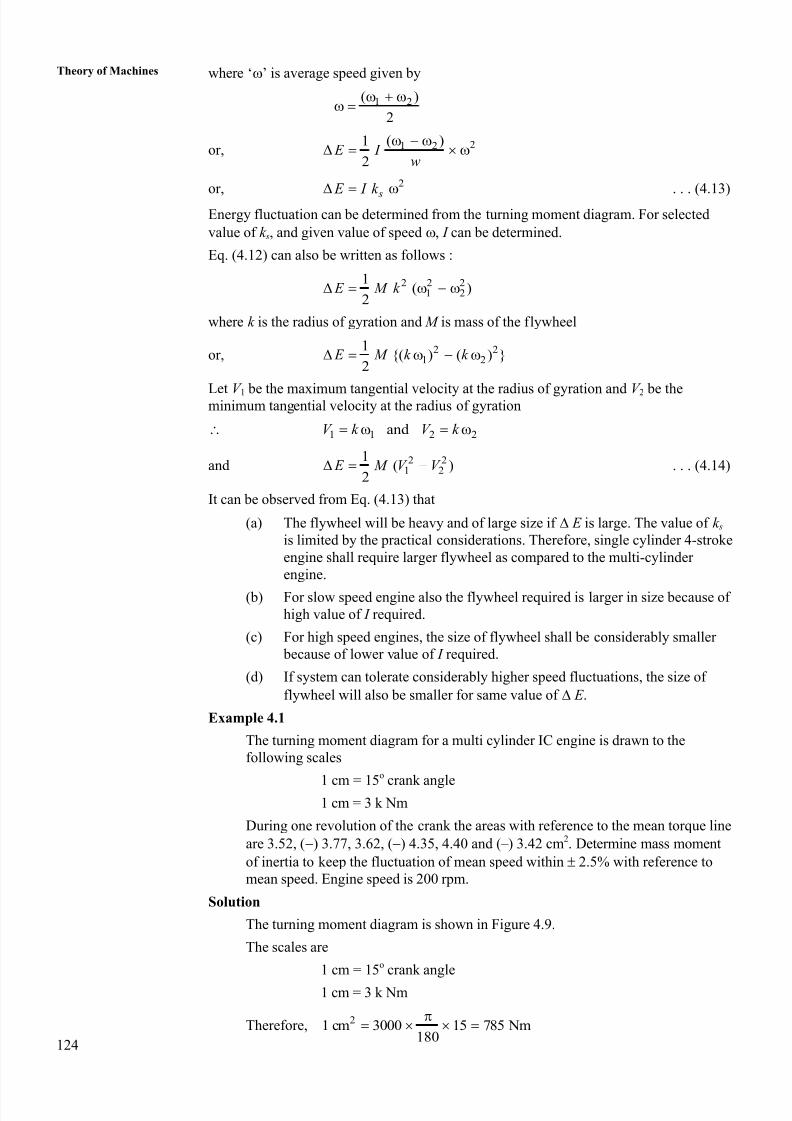
Example 4.1
The turning moment diagram for a multi cylinder IC engine is drawn to the
following scales
1 cm = 15
o
crank angle1 cm = 3 k Nm
During one revolution of the crank the areas with reference to the mean torque line
are 3.52, () 3.77, 3.62, () 4.35, 4.40 and ( – ) 3.42 cm2. Determine mass moment
of inertia to keep the fluctuation of mean speed within 2.5% with reference to
mean speed. Engine speed is 200 rpm.
Solution
The turning moment diagram is shown in Figure 4.9.
The scales are
1 cm = 15o crank angle
1 cm = 3 k Nm
Therefore, 21 cm 3000 15 785 Nm
180
8/20/2019 Flywheel Nice Material
http://slidepdf.com/reader/full/flywheel-nice-material 11/21
125
Flywheel
Figure 4.9 : Figure for Example 4.1
The overall speed fluctuation = 2 2.5%
Coefficient of speed fluctuation ‘k s’ = 0.05
Engine speed = 200 rpm
2 200
20.93 r/s
60
Let Energy level at a is ‘ E ’ cm2
Energy level at b is E b = E + 3.52
Energy level at c is E c = E b – 3.77 = E + 3.52 – 3.77 = E – 0.25
Energy level at d is E d = E c + 3.62 = E – 0.25 + 3.62 = E + 3.37
Energy level at e is E e = E d – 4.35 = E + 3.37 – 4.35 = E – 0.98
Energy level at f is E f = E e + 4.40 = E – 0.98 + 4.40 = E + 3.42
Energy level at g is E g = E f – 3.42 = E + 3.42 – 3.42 = E
Energy level at the end of cycle and at the beginning of the cycle should be same.By comparing the values of energies at various points, we get
Maximum energy is at ‘b’, i.e. E max = E + 3.52
Minimum energy is at ‘e’, i.e. E min = E – 0.98
Since, 2 s E I k
23532.5 0.05 (20.93) I
or, 2
2
3532.5 3532.5169 kgm
20.90.05 (20.93) I
Example 4.2
A single cylinder four-stroke petrol engine develops 18.4 kW power at a mean
speed of 300 rpm. The work done during suction and exhaust strokes can be
neglected. The work done by the gases during explosion strokes is three times the
work done on the gases during the compression strokes and they can be
represented by the triangles. Determine the mass of the flywheel to prevent a
fluctuation of speed greater than 2 per cent from the mean speed. The flywheel
diameter may be taken as 1.5 m.
Solution
Power developed ‘ P ’ = 18.4 kW Mean speed ‘ N ’ = 300 rpm
Fluctuation of speed = 2%
a b c d
e
T o r q u e ( M )
3.52
3.77
4.62
3.35
4.40
f
3.42
8/20/2019 Flywheel Nice Material
http://slidepdf.com/reader/full/flywheel-nice-material 12/21
126
Theory of Machines Diameter of flywheel = 1.5 m
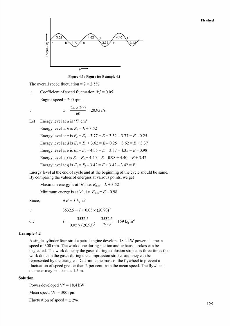
The turning moment diagram is shown in Figure 4.10.
Figure 4.10 : Figure for Example 4.2
Let height of the triangle in compression stroke by ‘ x’ and that in explosion stroke
be ‘ y’. Since, work done in explosion stroke is three times to that in compression
stroke.
3 or 32 2
y x y x
The net work done per second = 18.4 1000 Nm
Numbers of cycles per second300
2.560 2
Therefore, work done per cycle18400
7360 Nm2.5
From turning moment diagram, work done per cycle ( )2 2 2
y x y x
( ) 73602
y x
or,7360 2
4687.9 y x
Substituting for y in the above expression.
4687.93 4687.9 or
2 x x x
or, x = 2343.95 kN
3 7031.85 Nm y x
Average net torque7360
586 Nm4
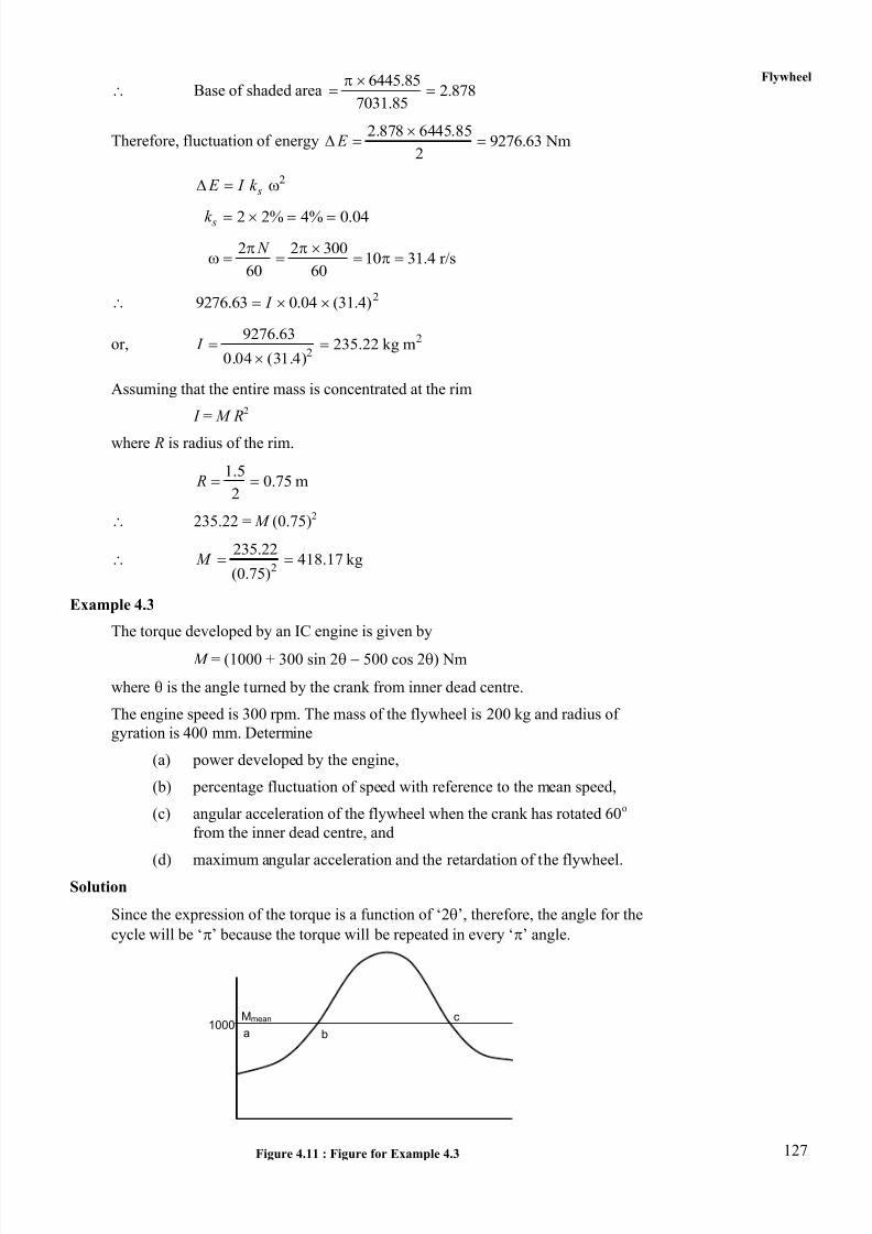
The fluctuation of energy will be provided by the shaded area shown inFigure 4.10. From the theory of similar triangles
Base of shaded area 7031.85 586
7031.85
y
2 3 4
x
O
T o r q u e
586 Nm
8/20/2019 Flywheel Nice Material
http://slidepdf.com/reader/full/flywheel-nice-material 13/21
127
Flywheel
Base of shaded area6445.85
2.8787031.85
Therefore, fluctuation of energy2.878 6445.85
9276.63 Nm2
E
2 s E I k
2 2% 4% 0.04 sk
2 2 30010 31.4 r/s
60 60
N
29276.63 0.04 (31.4) I
or, 2
2
9276.63235.22 kg m
0.04 (31.4) I
Assuming that the entire mass is concentrated at the rim
I = M R2
where R is radius of the rim.
1.50.75 m
2 R
235.22 = M (0.75)2
2
235.22418.17 kg
(0.75) M
Example 4.3
The torque developed by an IC engine is given by
M = (1000 + 300 sin 2 500 cos 2) Nm
where is the angle turned by the crank from inner dead centre.
The engine speed is 300 rpm. The mass of the flywheel is 200 kg and radius of
gyration is 400 mm. Determine
(a) power developed by the engine,
(b) percentage fluctuation of speed with reference to the mean speed,
(c) angular acceleration of the flywheel when the crank has rotated 60o
from the inner dead centre, and
(d) maximum angular acceleration and the retardation of the flywheel.Solution
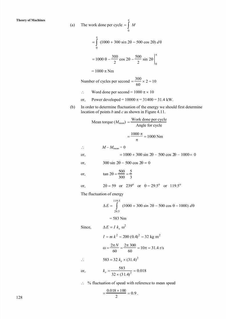
Since the expression of the torque is a function of ‘2’, therefore, the angle for the
cycle will be ‘’ because the torque will be repeated in every ‘’ angle.
Figure 4.11 : Figure for Example 4.3
a b
c 1000
Mmean
8/20/2019 Flywheel Nice Material
http://slidepdf.com/reader/full/flywheel-nice-material 14/21
128
Theory of Machines
(a) The work done per cycle
0
M
0
(1000 300 sin 2 500 cos 2 ) d
0
300 5001000 cos 2 sin 22 2
= 1000 Nm
Number of cycles per second300
2 1060
Word done per second = 1000 10
or, Power developed = 10000 = 31400 = 31.4 kW.
(b) In order to determine fluctuation of the energy we should first determine
location of points b and c as shown in Figure 4.11.
Mean torque ( M mean)Work done per cycle
Angle for cycle
10001000 Nm
M – M mean = 0
or, 1000 300 sin 2 500 cos 2 1000 0
or, 300 sin 2 500 cos 2 0
or,500 5
tan 2300 3
or, o o o2 59 or 239 or 29.5 or 119.5
The fluctuation of energy
119.5
29.5
(1000 300 sin 2 500 cos 1000) E d
= 583 Nm
Since, 2 s E I k
2 2 2200 (0.4) 32 kg m I m k
2 2 30010 31.4 r/s
60 60
N
2583 32 (31.4) sk
or,2
5830.018
32 (31.4) sk
% fluctuation of speed with reference to mean speed
0.018 1000.9
2
.
8/20/2019 Flywheel Nice Material
http://slidepdf.com/reader/full/flywheel-nice-material 15/21
129
Flywheel(c) Acceleration is produced by the excess torque.
Excess torque = 300 sin 2 400 cos 2
when = 60o
Excess torque at o o o60 300 sin 120 500 cos 120
259.8 250 509.8
I = 509.8
or, Angular acceleration509.8
15.9332
or, 15.93 r/s
(d) Maximum acceleration shall occur where torque is maximum and minimum
acceleration will occur where torque is minimum.
2 300 cos 2 2 500 sin 2 0dM
d
or, tan 2 = 0.6
2 = 149.04o, 329.04
o or = 74.52
o, 164.52
o
when = 74.52o; M = 1583.1 Nm
when = 164.52o; M = 416.9 Nm
For maximum acceleration 1583.1 1000 I
2max
583.118.22 r/s
32
For minimum acceleration 416.9 1000 I
2min
583.118.22 r/s
32
Example 4.4
A three cylinder two-stroke engine has its cranks 120o apart. The speed of the
engine is 600 rpm. The turning moment diagram for each cylinder can be
represented by a triangle for one expansion stroke with a maximum value of one
stroke with a maximum value of 600 Nm at 60o from the top dead centre. The
turning moment in other stroke is zero for all the cylinders. Determine :(a) the power developed by the engine,
(b) the coefficient of fluctuation of speed with a flywheel having mass
10 kg and radius of gyration equal to 0.5 m,
(c) the coefficient of fluctuation of energy, and
(d) the maximum angular acceleration of the flywheel.
Solution
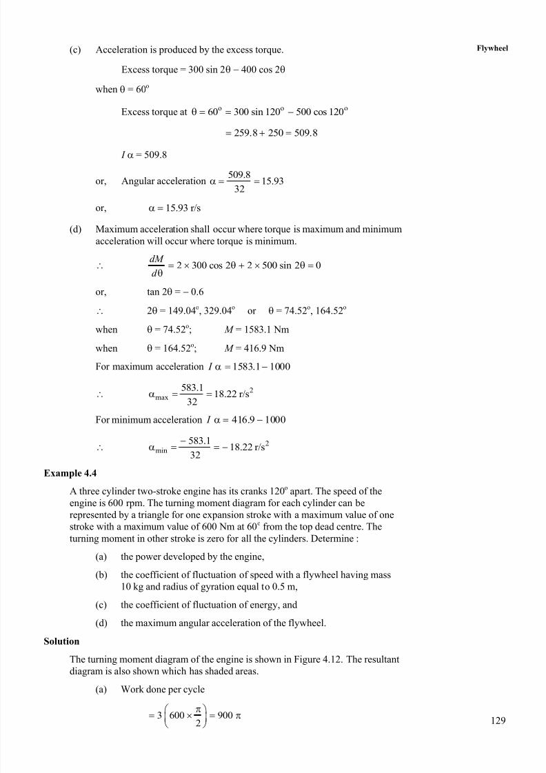
The turning moment diagram of the engine is shown in Figure 4.12. The resultant
diagram is also shown which has shaded areas.
(a) Work done per cycle
3 600 9002
8/20/2019 Flywheel Nice Material
http://slidepdf.com/reader/full/flywheel-nice-material 16/21
130
Theory of MachinesMean torque
900450 Nm
2av M
Power developed2
' '60
av
N P M
2 600450
60
4500 2
9000
= 28260 Watt
or, 28.260 kW P
Figure 4.12 : Figure for Example 4.4
(b) Mass moment of inertia of the flywheel
‘ I ’ = m k 2
= 10 (0.5)2
= 2.5 kg m2
The fluctuation of energy is given by the shaded area above the mean
line
(600 450) 60 15078.5 Nm
2 180 6 E
Speed,2 2 600
20 62.8 r/s
60 60
N w
2 s E I k w
or, 78.54 = 2.5 k s (62.8)2
or,2
78.5 78.5
2.5 3943.842.5 (62.8) sk
Coefficient of fluctuation = 0.008.
(c) Coefficient of fluctuation of energy E
E
78.5 and 900 E E
Therefore, coefficient of fluctuation of energy78.5
0.028900
0 60 120 180 240 300 360
600
450 60
Mav
M
8/20/2019 Flywheel Nice Material
http://slidepdf.com/reader/full/flywheel-nice-material 17/21
131
Flywheel(d) Maximum excess torque = 600 – 450 = 150 Nm
Let angular acceleration be ‘’.
I max = 150
2max
150 15060 r/s
2.5 I
4.5.2 Mass Moment of Inertia of Flywheel for a Punching Press
In this case torque supplied is constant because these machines are driven by the electric
motor but the demand torque, i.e. resisting torque varies during cycle. The example of
them are punching press, shearing machine, etc.
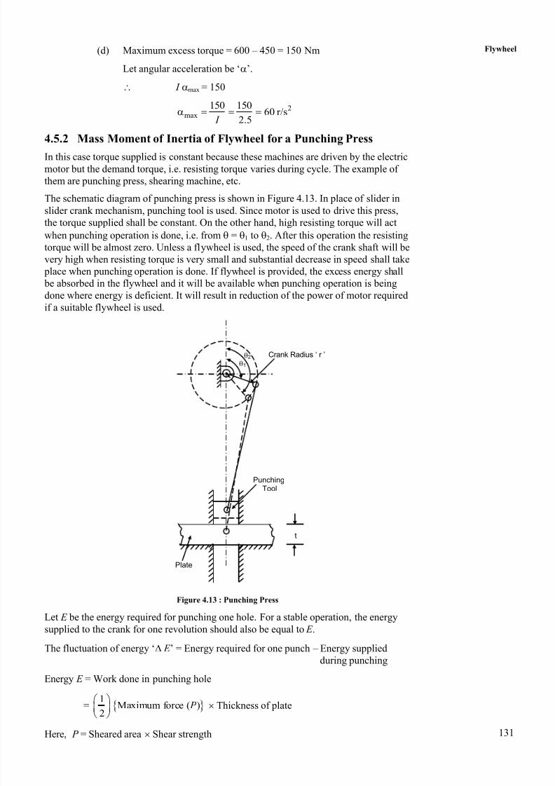
The schematic diagram of punching press is shown in Figure 4.13. In place of slider in
slider crank mechanism, punching tool is used. Since motor is used to drive this press,
the torque supplied shall be constant. On the other hand, high resisting torque will act
when punching operation is done, i.e. from = 1 to 2. After this operation the resisting
torque will be almost zero. Unless a flywheel is used, the speed of the crank shaft will be
very high when resisting torque is very small and substantial decrease in speed shall take
place when punching operation is done. If flywheel is provided, the excess energy shall be absorbed in the flywheel and it will be available when punching operation is being
done where energy is deficient. It will result in reduction of the power of motor required
if a suitable flywheel is used.
Figure 4.13 : Punching Press
Let E be the energy required for punching one hole. For a stable operation, the energy
supplied to the crank for one revolution should also be equal to E .
The fluctuation of energy ‘ E ’ = Energy required for one punch – Energy supplied
during punching
Energy E = Work done in punching hole
= 1
Maximum force ( )2
P Thickness of plate
Here, P = Sheared area Shear strength
1 2 Crank Radius ‘ r ’
PunchingTool
Plate
t
8/20/2019 Flywheel Nice Material
http://slidepdf.com/reader/full/flywheel-nice-material 18/21
132
Theory of MachinesEnergy supplied during punching 2 1( )
2
E
2 1 2 1( )1
2 2
E E E E
Angles 1 and 2 should be in radians.
Let t be the thickness of the plate in which holes are to be punched.
s be the length of the stroke.
r be the length of the crank.
l be the length of the connecting rod.
1 and 2 can be determined geometrically if r , l and t are known.
The rough estimate can also be made as follows :
2 1
2 2 4
t t
s r
22 1( )1 1
2 4 s
t E E E I k
r
. . . (4.15)
The mass moment of inertia of the flywheel for a given value of coefficient of
fluctuation of speed can be determined. In order to reduce the size of flywheel it will be
better to mount the flywheel on a shaft having higher value of ‘’.
SAQ 5
Between the motor shaft and shaft carrying the punching tool there is heavy speed
reduction. On which shaft flywheel should be mounted in order to have smaller
flywheel.
4.5.3 Design of Flywheel
The flywheel has a heavy rim which is connected to the hub by several arms. The mass
moment of inertia is largely contributed by the rim. From experience, it is known that
85 to 90% of the total mass can be assumed to be estimated in the rim. 15 to 10 percent
of the mass is in the hub and arms.
The mean rim radius, Rm, depends on allowable tensile strength, a, mass density, , andmaximum angular velocity, max, and it is given by
1
2
max
1
am R
The cross-section of the rim is rectangular having more width than the thickness. The
width may be about 2.5 times of thickness. The material used is generally cast iron.
Example 4.5
The resisting torque on the crank of a riveting machine is 200 Nm for first 90o,
from 90o to 135o is 1600 Nm then it drops linearly to 200 Nm upto 180o and
remains the same upto 360o. The duration of cycle is 2 sec. The motor driving the
machine, however, has a speed of 1450 rpm and it delivers constant torque. The
crank shaft of the machine is geared to the motor shaft. The speed fluctuation is
limited to 2% of mean speed. Determine :
8/20/2019 Flywheel Nice Material
http://slidepdf.com/reader/full/flywheel-nice-material 19/21
133
Flywheel(a) power of the motor, and
(b) moment of inertia of the flywheel mounted on the motor shaft.
Solution
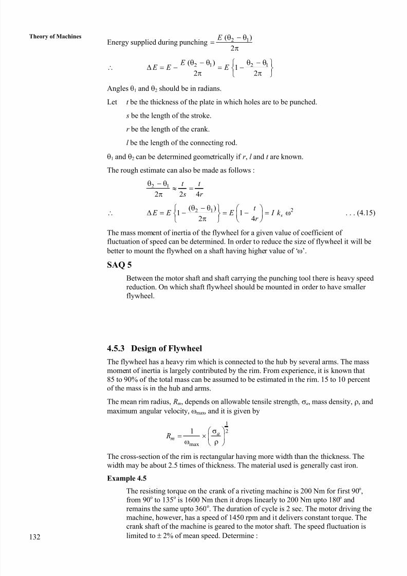
In this problem, torque supplied is constant and demand torque is fluctuating. The
demand torque is shown in Figure 4.14.
(a) The energy required per cycle
3 1200 1600 (1600 200) 200
2 4 2 4 2 4 E
3200 1600 1400 200
2 4 8 4
700300 400 50 (750 175) 925
4
= 2904.5 Nm
The duration of the cycle is 2 seconds
Energy required per second2904.5
1452.252
Power of motor required, p = 1.452 kW.
Figure 4.14 : Figure for Example 4.5
(b) The average torque2904.5
2 2av
E M
or, M av = 462.5 Nm
The shaded portion is fluctuation of energy. Therefore,
(1600 462.5)3 (1600 462.5) 4
(1600 462.5)4 2 2 (1600 200)
E
21137.5
1137.54 1400 4
(1137.5 924.22) 1618.45 Nm4
1600
462.5
200
Mav
M
90 135 2
8/20/2019 Flywheel Nice Material
http://slidepdf.com/reader/full/flywheel-nice-material 20/21
134
Theory of Machines 2 s E I k
2 2 1450151.76 r/s
60 60
N
Coefficient of speed fluctuation2 2
0.04100
sk
2
1618.45 0.04 (151.76) I
or, 21618.451.76 kg m
0.04 23032.1 I
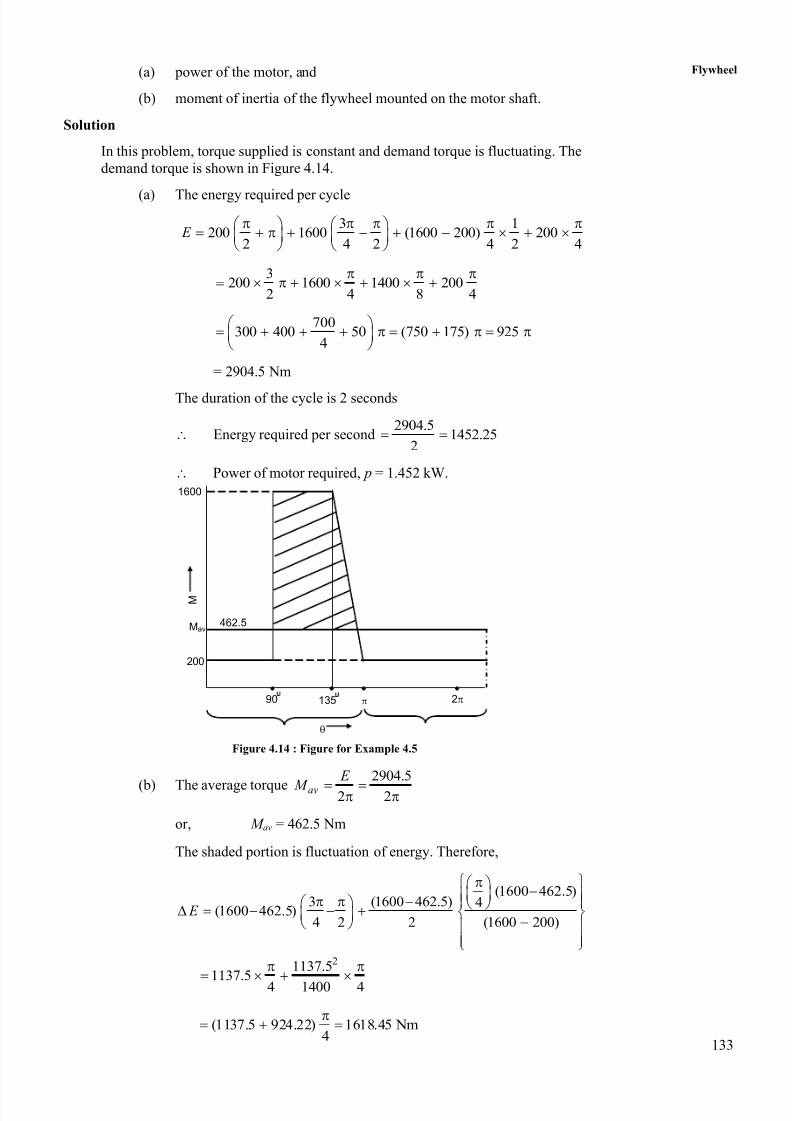
Example 4.6
A punching machine punches 6 holes per minute. The diameter of each hole is
4 cm and thickness of the plate is 3 cm. The stroke of the punch is 10 cm. The
work done per square cm of sheared area is 600 J. The maximum speed of the
flywheel at its radius of gyration is 28 m/s. Determine mass of the flywheel
required so that its speed at its radius gyration does not fall below 26 m/s.
Determine power of the motor required.
Solution
The sheared area of the hole = Circumference depth
24 3 12 37.68 cm
Energy required per hole E = 37.68 600 = 22608 J
Number of holes per minute = 6
Energy required per minute = 6 22608
Energy required per second6 22608
2260.860
Power of motor required 2260.8 2.2608 kW 2.26 kW1000
Fluctuation of energy 2 2 21 2
1( )
2 s E I k I
2 2 21 2( )
2
M k
2 21 2{( ) ( ) }
2
M k k
2 2max min( )
2
M V V
The fluctuation of energy
Thinckess of plate1
2 stroke E E
3 322608 1 22608 1
2 10 20
22608 (1 0.15)
22608 0.85 19216.8 J
2 2 10819216.8 (28 26 ) 542 2
M M M
or, M = 355.87 kg.
8/20/2019 Flywheel Nice Material
http://slidepdf.com/reader/full/flywheel-nice-material 21/21
135
Flywheel4.6 SUMMARY
It has been observed that the usage of reciprocating engine mechanism results in
fluctuation of energy. In such cases use of flywheel is necessary in order to reduce
fluctuation in speed during the cycle. A prime mover of lower power can serve the
purpose if a flywheel is used. For designing a flywheel, the connecting rod is replaced by
a dynamically equivalent link so that the reciprocating mass can be determined more
accurately.
Flywheel absorbs excess energy in the form of kinetic energy during period of
harvestation and supplies it whenever the energy supplied is less during the period of
starvation. In case of single cylinder four stroke IC engine, flywheel supplies energy
during suction, compression and exhaust strokes and stores excess energy supplied
during expansion stroke. Therefore, flywheel facilitates running of the engine and
reduces fluctuations in the speed.
In case of punching machine, energy is supplied by the motor for which torque is
constant but energy required is very high when punching operation is done. The flywheel
supplies energy during punching and stores energy during idle time when no punching is
done. This results in requirements of lower power motor and having lower fluctuation inthe speed.
4.7 KEY WORDS
Dynamically Equivalent Link : It is link which has point masses at two points
such that (a) total mass is same, (b) centre of
gravity is at the same position, and (c) mass
moment of inertia about an axis through CG
remains same.
Turning Moment : It is the moment of the force at crank pin with
respect to the crank centre.
Turning Moment Diagram : It is the diagram plotted with turning moment on
the Y -axis and angle of rotation of crank for one
cycle on the X -axis.
Fluctuation of the Energy : It is the difference between the maximum energy
at a point on the mean torque line and minimum
energy at another point on the mean torque line.
Coefficient of the : It is the ratio of fluctuation of energy to the energy
Fluctuation Energy of the cycle.
Fluctuation of Speed : It is the difference in maximum angular speed andminimum angular speed.
Coefficient of Fluctuation : It is the ratio of fluctuation of speed to the average
of Speed angular speed.
4.8 ANSWERS TO SAQs
Please refer the preceding text for all the answers to SAQs.


![Design Analysis and Weight Reduction of Car Flywheel … Analysis and Weight...Sushama G Bawane et al. (2012) [3] had proposed flywheel design, and analysis the material selection](https://img.dokumen.tips/doc/110x75/5b271d467f8b9a42318b495a/design-analysis-and-weight-reduction-of-car-flywheel-analysis-and-weightsushama.jpg)