Embed Size (px)
Citation preview

660 West Avenue O, Palmdale, CA 93551Phone (661) 233-2000 Fax (661) 233-2001www.usaltg.com
S P E C I F I C A T I O N S
SOLID STATE AREA L IGHTINGPROJECT NAME:
FIXTURE TYPE:
L U M S E R I E S - P L E D
PATENT PENDING
L U M P L E D
HOUSINGHeavy cast low copper aluminum assembly (A360 alloy, <0.4% copper). Housing attaches to pole via a one piece, extruded aluminum arm with centering guides for internal draw bolts. Housing/pole junction is gasketed. All exposed hardware is stainless steel. Internal protected hardware is electro-zinc plated.
OPTICSEmitters (LED’s) are arrayed on a metal core PCB panel with each emitter located on a copper thermal transfer pad and enclosed by an LED refractor. In asymmetric distributions, a micro-reflector inside the refractor re-directs the house side emitter output towards the street side and functions as a house side shielding element. Refractors are injection molded H12 acrylic. Each LED refractor is sealed to the PCB over an emitter and all refractors are retained by an aluminum frame. Any one Panel, or group of Panels in a luminaire, have the same optical pattern. LED refractors produce standard site/area distributions. Panels are field replaceable and field rotatable in 90° increments.
LED DRIVERSDrivers are UL and cUL recognized mounted on a single plate and factory prewired with quick-disconnect plugs. Constant current driver is electronic and has a power factor of >0.90 and a minimum operating temperature of -40°F. In-line terminal blocks facilitate wiring between the driver and optical arrays. Drivers accept an input of 120-277V, 50/60Hz or 347V-480V, 50,60Hz. (0 - 10V dimmable driver is standard. Driver has a minimum of 3KV internal surge protection. Luminaire supplied with 20KV surge protector for field accessible installation.)
MOUNTINGS Arm - One piece heavy wall extruded aluminum with internal draw bolt guides. Arm is secured to housing and pole with stainless steel draw bolts.
Wall - Heavy wall extruded aluminum arm with draw bolts integrates with a cast aluminum wall plate and mounting bracket.
FINISHElectrostatically applied TGIC Polyester Powder Coat on substrate prepared with 20 PSI power wash at 140°F. Four step sand blast and iron phosphate pretreatment for protection and paint adhesion. 400°F bake for maximum hardness and durability. Texture finish is standard.
TM
2017287
SIDE VIEWFRONT VIEW
6.5"(165mm)
TOP VIEW
16"(406mm)
16"(406mm)
22"(559mm)
U.S. Architectural L ight ing
S P E C I F I C A T I O N S
LUM SERIES - PLED
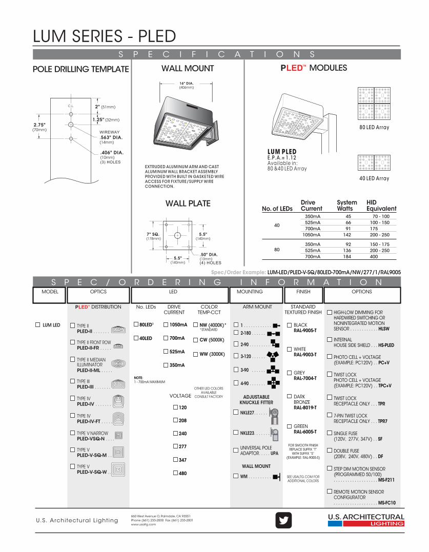
S P E C / O R D E R I N G I N F O R M A T I O N
660 West Avenue O, Palmdale, CA 93551Phone (661) 233-2000 Fax (661) 233-2001www.usaltg.com
LUM PLEDE.P.A.= 1.12Available in:80 &40 LED Array
MODEL OPTICS LED MOUNTING FINISH OPTIONS
Spec/Order Example: LUM-LED/PLED-V-SQ/80LED-700mA/NW/277/1/RAL9005
VOLTAGE
No. LEDs COLORTEMP-CCT
DRIVECURRENT
120
208
240
277
347
480
NW (4000K)**STANDARD
CW (5000K)
WW (3000K)
LUM LED
DARKBRONZERAL-8019-T
GREENRAL-6005-T
WHITERAL-9003-T
GREYRAL-7004-T
BLACKRAL-9005-T
FOR SMOOTH FINISH REPLACE SUFFIX “T”
WITH SUFFIX “S”(EXAMPLE: RAL-9005-S)
SEE USALTG.COM FOR ADDITIONAL COLORS
STANDARDTEXTURED FINISH
ARM MOUNT
80 LED Array
40 LED Array
40LED
1050mA
700mA
525mA
350mA
16" DIA.(406mm)
EXTRUDED ALUMINUM ARM AND CAST ALUMINUM WALL BRACKET ASSEMBLY PROVIDED WITH BUILT IN GASKETED WIRE ACCESS FOR FIXTURE/SUPPLY WIRE CONNECTION.
2.75"(70mm)
2" (51mm)
1.25" (32mm)
C.L.
WIREWAY.563" DIA.(14mm)
.406" DIA.(10mm)(3) HOLES
POLE DRILLING TEMPLATE
WALL PLATE
WALL MOUNT
.50" DIA. (13mm)(4) HOLES
5.5"(140mm)
5.5"(140mm)
7" SQ. (178mm)
MODULESTM
WALL MOUNT
2-180 . . . . . .
4-90 . . . . . . .
1 . . . . . . . . . . . .
2-90 . . . . . . . . .
3-90 . . . . . .
3-120 . . . . . . .
WM . . . . . . . . . .
ADJUSTABLEKNUCKLE FITTER
NKLE27. . . . . .
NKLE23. . . . . . .
UNIVERSAL POLEADAPTOR. . . . . UPA
90 0
30
60
30
60
80LED1
NOTE:1 - 700mA MAXIMUM
No. of LEDsDriveCurrent
SystemWatts
HIDEquivalent
40
80
350mA525mA700mA
1050mA
350mA525mA700mA
45 6691
142
92136184
70 - 100100 - 150175200 - 250
150 - 175200 - 250400
DISTRIBUTIONTM
TYPE IV PLED-IV-FT . . . . .
TYPE III PLED-III . . . . . . .
TYPE IV PLED-IV . . . . . . .
TYPE II PLED-II . . . . . . .
TYPE VPLED-V-SQ-M . .
TYPE VPLED-V-SQ-W . .
TYPE II FRONT ROW PLED-II-FR . . . . .
TYPE V NARROWPLED-VSQ-N . . . .
TYPE II MEDIANILLUMINATORPLED-II-ML . . . . .
DOUBLE FUSE (208V, 240V, 480V) . . DF
PHOTO CELL + VOLTAGE (EXAMPLE: PC120V) . . PC+V
TWIST LOCKPHOTO CELL + VOLTAGE(EXAMPLE: PC120V) . . TPC+V
7-PIN TWIST LOCKRECEPTACLE ONLY . . . TPR7
TWIST LOCKRECEPTACLE ONLY . . . TPR
SINGLE FUSE (120V, 277V, 347V) . . SF
REMOTE MOTION SENSORCONFIGURATOR. . . . . . . . . . . . . . . . . . . MS-FC10
STEP DIM MOTION SENSOR (PROGRAMMED 50/100). . . . . . . . . . . . . . . . . . . MS-F211
INTERNALHOUSE SIDE SHIELD . . . HS-PLED
HIGH-LOW DIMMING FORHARDWIRED SWITCHING ORNONINTEGRATED MOTIONSENSOR . . . . . . . . . . . . HLSW
OTHER LED COLORSAVAILABLE
CONSULT FACTORY
U.S. Architectural L ight ing
LUM SERIES - PLED
660 West Avenue O, Palmdale, CA 93551Phone (661) 233-2000 Fax (661) 233-2001www.usaltg.com
U.S. Architectural L ight ing
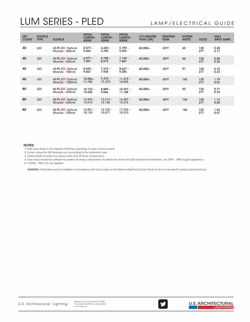
L A M P / E L E C T R I C A L G U I D E
INITIAL LUMENS -4000K
L70 GREATER THAN (HR)
STARTINGTEMP. VOLTS
SYSTEMWATTS
MAXINPUT AMPS
LEDCOUNT
SOURCETYPE SOURCE
NOTES:1.2.3.4.5.
Max Input Amps is the highest of starting, operating, or open circuit currentsLumen values for LED Modules vary according to the distribution typeSystem Watts includes the source watts and all driver components.Fuse value should be sufficient to protect all wiring components. For electronic driver and LED component protection, use 10KV – 20KV surge suppressors.L70(9K) – TM-21 6x rule applied
WARNING: All fixtures must be installed in accordance with local codes or the National Electrical Code. Failure to do so may result in serious personal injury.
60,000+ -20°F 120277
45 0.380.17
40 LED 40 Optical Module - 350mA
60,000+ -20°F 120277
66 0.580.25
40 LED 40 Optical Module - 525mA
®
60,000+ -20°F 120277
91 0.760.33
40 LED 40 Optical Module - 700mA
®
60,000+ -20°F 120277
142 1.190.52
40 LED 40 Optical Module - 1050mA
®
60,000+ -20°F 120277
92 0.770.34
80 LED 80 Optical Module - 350mA
60,000+ -20°F 120277
136 1.140.50
80 LED 80 Optical Module - 525mA
®
60,000+ -20°F 120277
184 1.540.67
80 LED 80 Optical Module - 700mA
®
®
8,425 –9,067
10,956 –11,792
5,077 –5,464
6,977 –7,507
10,153 –10,926
13,952 –15,015
16,851 –18,139
INITIAL LUMENS -3000K
7,376 –7,938
9,592 –10,324
4,445 –4,784
6,108 –6,573
8,889 –9,566
12,215 –13,146
14,752 –15,877
INITIAL LUMENS -5000K
8,627 –9,285
11,219 –12,075
5,199 –5,595
7,144 –7,687
10,397 –11,188
14,287 –15,376
17,254 –18,570