Embed Size (px)
Citation preview
Data Aire, Inc.230 W. BlueRidge Avenue
Orange, CA 92865www.dataaire.com
FLUID COOLER (Dry Cooler)EC and PSC Fans
User Manual
CONGRATULATIONS ON THE SELECTION OF A DATA AIRE PRECISION ENVIRONMENTAL CONTROL SYSTEM. PROPER INSTALLATION, OPERATION AND MAINTENANCE OF THIS EQUIPMENT WILL ENSURE YEARS OF OPTIMAL PERFORMANCE.
NOTE: This manual is intended to assist trained service personnel by providing necessary guidelines for this particular equipment. Service to Data Aire units should be done by qualified individuals with an adequate background in areas such as HVAC, electrical, plumbing and electronics, as applicable.
WARNING: Service performed by unauthorized or unqualified technicians may void manufacturers’ warranties and could result in property damage and/or personal injury.
Special care should be given to those areas where these symbols appear.
Data Aire, Inc. reserves the right to make design changes for the purpose of product improvement or to withdraw any design without notice.
3
Table of Contents1.0 INTRODUCTION .....................................................................................................4
1.1 Model Identification ...........................................................................................41.2 Inspection ............................................................................................................41.3 Paperwork ...........................................................................................................51.4 Storage ................................................................................................................51.5 Location ...............................................................................................................51.6 Leg Assembly .......................................................................................................61.7 Rigging .................................................................................................................61.8 Installation ..........................................................................................................71.9 Piping ....................................................................................................................7
2.0 GLYCOL SYSTEMS ................................................................................................92.1 Glycol Concentration .......................................................................................92.2 GHFC/DAFC Fluid Cooler Internal Volume ...................................................92.3 Copper Piping Internal Volume ......................................................................102.4 Freezing Point of Aqueous Solutions ..........................................................102.5 Mixing Glycol and Water .................................................................................10
3.0 ELECTRICAL CONNECTIONS ...........................................................................113.1 Electrical Service ...........................................................................................113.2 Nameplate Ratings ............................................................................................113.3 Grounding .........................................................................................................113.4 Voltage Tolerance ...........................................................................................113.5 Auxiliary Control Wiring ................................................................................113.6 Wiring Diagrams ...............................................................................................12
4.0 CONTROLS ...........................................................................................................134.1 Permanent-Split Capacitor (PSC) Type Fan Motors ...................................134.2 Electronically Commutated (EC) Axial Fan Motors (Optional) ................134.3 Energy Saver Cooling (Optional) ..................................................................13
4.3.1 Systems with PSC Fan Motor(s) ..................................................................134.3.2 Systems with EC Fan Motor(s) (Optional) ....................................................13
5.0 WARRANTY ...........................................................................................................15
6.0 PREVENTIVE MAINTENANCE ...........................................................................156.1 Maintenance Functions ...................................................................................156.2 Coil Cleaning ....................................................................................................16
6.2.1 When to Clean ..............................................................................................166.2.2 What to Use ..................................................................................................166.2.3 How to Clean ................................................................................................16
7.0 CONTACT DATA AIRE .........................................................................................17
8.0 APPENDIX A..........................................................................................................18
4
1.0 INTRODUCTION
The Data Aire Fluid Cooler is a completely closed loop industrial grade dry type fluid cooler available in a wide range of sizes for process cooling applications. A closed-circuit design conserves both water and energy and is environmentally friendly. The DAFC/GHFC Series effectively eliminates scaling and corrosion, water treatment and sewage costs.
All fluid coolers are provided with control box and unit mounted controls (including pump contactor). Motors are thermally protected direct drive type. Fan cycling is controlled by ambient thermostats or electronic temperature controller on dry coolers with more than one fan.
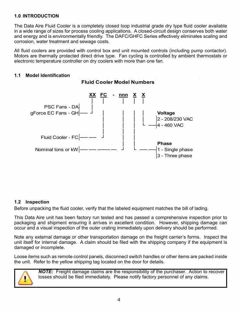
1.1 Model Identification
XX FC - nnn X X│ │ │ │ │
PSC Fans - DA │gForce EC Fans - GH ────┘ │ │ │ │ Voltage
│ │ │ │ 2 - 208/230 VAC│ │ │ └ ────4 - 460 VAC│ │ │
Fluid Cooler - FC ────────┘ │ ││ │ Phase
Nominal tons or kW ────────────────┘ └ ────────1 - Single phase3 - Three phase
Fluid Cooler Model Numbers
1.2 InspectionBefore unpacking the fluid cooler, verify that the labeled equipment matches the bill of lading.
This Data Aire unit has been factory run tested and has passed a comprehensive inspection prior to packaging and shipment ensuring it arrives in excellent condition. However, shipping damage can occur and a visual inspection of the outer crating immediately upon delivery should be performed.
Note any external damage or other transportation damage on the freight carrier’s forms. Inspect the unit itself for internal damage. A claim should be filed with the shipping company if the equipment is damaged or incomplete.
Loose items such as remote control panels, disconnect switch handles or other items are packed inside the unit. Refer to the yellow shipping tag located on the door for details.
NOTE: Freight damage claims are the responsibility of the purchaser. Action to recover losses should be filed immediately. Please notify factory personnel of any claims.

5
1.3 PaperworkEach Data Aire unit ships with a start-up sheet that should be completed during installation. Also included in the paperwork is a warranty/information packet that provides important wiring diagrams, specific component literature, warranty registration cards and other valuable paperwork including a copy of this Installation, Operation and Maintenance Manual (IOM). A yellow tag is attached to the outside panel to indicate articles that may have been packaged and shipped loose within the unit that are not factory mounted.
NOTE: It is the responsibility of the installing contractor to return the start-up sheet and warranty registration card to Data Aire for proper activation of the unit warranty. Failure to do so may cause delays and in some cases void the warranty.
1.4 StorageData Aire equipment comes ready for immediate installation. However, in some instances, it may be necessary to store the equipment for a period of time. If you must store the equipment it should be done in a dry area, out of the weather, protected from freezing temperatures, protected from damage by other equipment in storage, or transportation equipment. Avoid stacking and frequent relocation.
If equipment is stored for longer than 30 days special precautions must be taken to avoid coil damage. All coils should be charged and sealed with a low pressure (less the 25 PSIG) inert gas, such nitrogen. This prevents contaminants from entering the coils. When the seal is broken at installation, the rush of escaping gas verifies the coil is still leak free. If coils are not charged and sealed, condensation mixes with air pollutants forming a weak acid and over time can cause pinhole leaks to develop in coil tubes.
When equipment is installed after storage, caution should be taken to inspect and replace damaged components, if required. All moving parts should be hand tested to ensure they are free and clear prior to start-up.
CAUTION: Complete system drain-down cannot be assured for this product. Freezing system fluids can rupture piping.
1.5 Location
Air cooled fluid coolers should be located in secure areas where service is easily accessible. Areas where public access is available should be avoided. Avoid areas that contribute to ice and snow accumulation. Fluid coolers should be located in clean areas free from debris or foreign matter that could block the coil surface. Avoid areas of hot air or fume exhaust. Fluid coolers should not be located near steam vents.
Remote fluid coolers are designed for outdoor application. The fluid cooler may be mounted either on a roof or concrete slab (ground level installations). Mounting must be level to assure proper fluid distribution through the coil as well as flooded suction for the pump. Mount on either steel channels or an I-beam to support the fluid cooler(s). Concrete slabs must be level and properly supported to prevent settling. Proper support should consider both the weight of the fluid cooler and the weight of the fluid (i.e., the roof or slab must be capable of supporting the fluid cooler(s) weight). Use of vibration pads or isolators is recommended.
Fluid coolers must be located in an area that will ensure free air flow into and out of the unit plus adequate service clearance. The unit should not be placed closer than 36” from any wall. Short circuiting of the air flow or the intake of warmer air from another unit will seriously degrade the performance of the air cooled fluid cooler. Do not connect ductwork to the coil inlet or fan outlet. Keep fan discharge away from building air intakes.
6
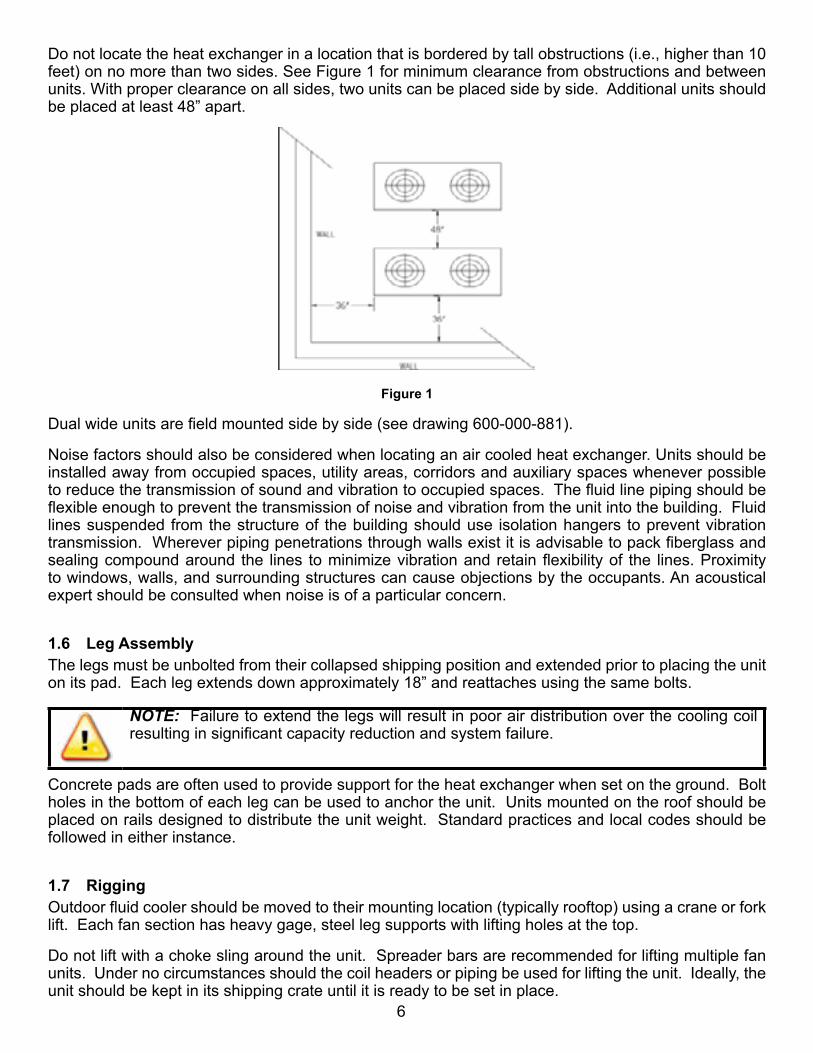
Do not locate the heat exchanger in a location that is bordered by tall obstructions (i.e., higher than 10 feet) on no more than two sides. See Figure 1 for minimum clearance from obstructions and between units. With proper clearance on all sides, two units can be placed side by side. Additional units should be placed at least 48” apart.
Figure 1
Dual wide units are field mounted side by side (see drawing 600-000-881).
Noise factors should also be considered when locating an air cooled heat exchanger. Units should be installed away from occupied spaces, utility areas, corridors and auxiliary spaces whenever possible to reduce the transmission of sound and vibration to occupied spaces. The fluid line piping should be flexible enough to prevent the transmission of noise and vibration from the unit into the building. Fluid lines suspended from the structure of the building should use isolation hangers to prevent vibration transmission. Wherever piping penetrations through walls exist it is advisable to pack fiberglass and sealing compound around the lines to minimize vibration and retain flexibility of the lines. Proximity to windows, walls, and surrounding structures can cause objections by the occupants. An acoustical expert should be consulted when noise is of a particular concern.
1.6 Leg AssemblyThe legs must be unbolted from their collapsed shipping position and extended prior to placing the unit on its pad. Each leg extends down approximately 18” and reattaches using the same bolts.
NOTE: Failure to extend the legs will result in poor air distribution over the cooling coil resulting in significant capacity reduction and system failure.
Concrete pads are often used to provide support for the heat exchanger when set on the ground. Bolt holes in the bottom of each leg can be used to anchor the unit. Units mounted on the roof should be placed on rails designed to distribute the unit weight. Standard practices and local codes should be followed in either instance.
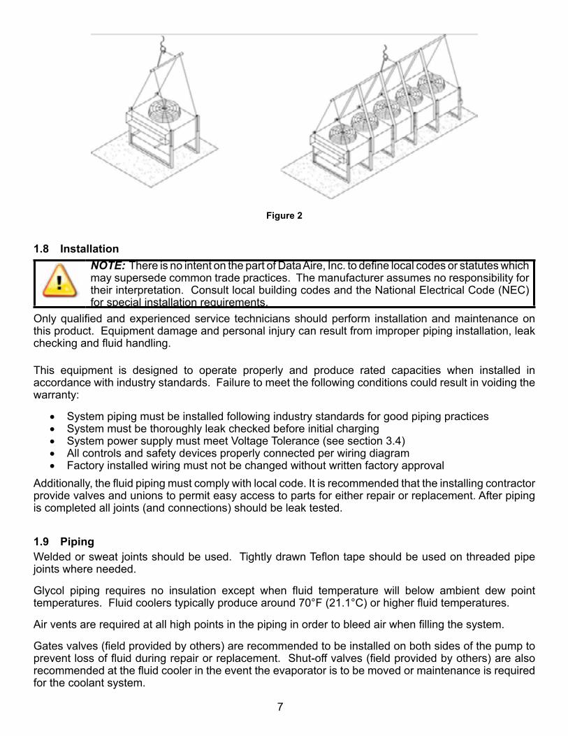
1.7 RiggingOutdoor fluid cooler should be moved to their mounting location (typically rooftop) using a crane or fork lift. Each fan section has heavy gage, steel leg supports with lifting holes at the top.
Do not lift with a choke sling around the unit. Spreader bars are recommended for lifting multiple fan units. Under no circumstances should the coil headers or piping be used for lifting the unit. Ideally, the unit should be kept in its shipping crate until it is ready to be set in place.
7
Figure 2
1.8 InstallationNOTE: There is no intent on the part of Data Aire, Inc. to define local codes or statutes which may supersede common trade practices. The manufacturer assumes no responsibility for their interpretation. Consult local building codes and the National Electrical Code (NEC) for special installation requirements.
Only qualified and experienced service technicians should perform installation and maintenance on this product. Equipment damage and personal injury can result from improper piping installation, leak checking and fluid handling.
This equipment is designed to operate properly and produce rated capacities when installed in accordance with industry standards. Failure to meet the following conditions could result in voiding the warranty:
• System piping must be installed following industry standards for good piping practices• System must be thoroughly leak checked before initial charging• System power supply must meet Voltage Tolerance (see section 3.4)• All controls and safety devices properly connected per wiring diagram• Factory installed wiring must not be changed without written factory approval
Additionally, the fluid piping must comply with local code. It is recommended that the installing contractor provide valves and unions to permit easy access to parts for either repair or replacement. After piping is completed all joints (and connections) should be leak tested.
1.9 PipingWelded or sweat joints should be used. Tightly drawn Teflon tape should be used on threaded pipe joints where needed.
Glycol piping requires no insulation except when fluid temperature will below ambient dew point temperatures. Fluid coolers typically produce around 70°F (21.1°C) or higher fluid temperatures.
Air vents are required at all high points in the piping in order to bleed air when filling the system.
Gates valves (field provided by others) are recommended to be installed on both sides of the pump to prevent loss of fluid during repair or replacement. Shut-off valves (field provided by others) are also recommended at the fluid cooler in the event the evaporator is to be moved or maintenance is required for the coolant system.
8
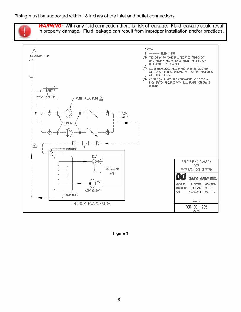
Piping must be supported within 18 inches of the inlet and outlet connections.
WARNING: With any fluid connection there is risk of leakage. Fluid leakage could result in property damage. Fluid leakage can result from improper installation and/or practices.
Figure 3

9
2.0 GLYCOL SYSTEMS
2.1 Glycol ConcentrationThe system must be filled with water and the appropriate amount of antifreeze (ethylene or propylene glycol) making an aqueous solution which protects against winter freezing. In order to achieve the approximate glycol concentration, it is necessary to know the total system volume. The total system volume consists of the fluid cooler volume, the evaporator unit volume and the volume of the inter-connecting piping.
The following tables can be used for arriving at an approximate system volume. After installation, the glycol percentage should be checked. The glycol percentage must be checked after installation and at regular intervals to ensure against freeze protection. Hydrometers are required to insure an accurate reading.
WARNING: Fluid coolers operating without glycol mixture and operating in ambient temperatures less than 32°F (0°C) must have adequate freeze protection.
2.2 GHFC/DAFC Fluid Cooler Internal VolumeModel Volume, Gallons Model Volume, Gallons
GHFC 021/ DAFC 06 2.5 GHFC 130/ DAFC 37 13.0GHFC 025/ DAFC 07 3.4 GHFC 141/ DAFC 40 16.3GHFC 032/ DAFC 09 4.2 GHFC 155/ DAFC 44 16.2GHFC 039/ DAFC 11 3.3 GHFC 176/ DAFC 50 20.3GHFC 053/ DAFC 15 4.9 GHFC 201/ DAFC 57 24.6GHFC 060/ DAFC 17 6.6 GHFC 215/ DAFC 61 19.6GHFC 074/ DAFC 21 7.4 GHFC 264/ DAFC 75 26.0GHFC 084/ DAFC 24 9.8 GHFC 281/ DAFC 80 32.6GHFC 099/ DAFC 28 12.3 GHFC 310/ DAFC 88 32.4GHFC 106/ DAFC 30 9.8 GHFC 352/ DAFC 100 40.6

10
2.3 Copper Piping Internal VolumePipe Diameter (Inches) Volume per 100 Feet of Pipe (Gallons)
5/8” 1.23/4” 1.87/8” 2.5
1-1/8” 4.31-5/8” 9.22-1/8” 16.12-5/8” 24.83-1/8 35.44-1/8 62.2
2.4 Freezing Point of Aqueous SolutionsETHYLENE GLYCOL
% by VOLUMEFREEZING POINT
DEGREES F (C)PROPYLENE GLYCOL
% by VOLUMEFREEZING POINT
DEGREES F (C)0 32 (0) 0 32 (0)10 20 (-6.6) 10 27 (-2.8)20 15 (-9.4) 20 18 (-8.8)30 4 (-15.6) 30 8 (-13.3)40 -13 (-25) 40 -6 (-21.1)50 -33 (-36.1) 50 -26 (-32.2)
2.5 Mixing Glycol and WaterIf possible, it is recommended to purchase the antifreeze solution already pre-mixed by the manufacturer. If this is not the case, always pre-mix the glycol and water prior to adding to the system. The chemical reaction between the two will release oxygen. Oxygen is extremely undesirable in a closed loop system.

11
3.0 ELECTRICAL CONNECTIONS
WARNING: The Data Aire cooling unit must be connected by a licensed and qualified electrician. Risk of electrical shock could result in injury or death. Disconnect all remote electrical power supplies prior to working on the unit.
NOTE: Disconnect switches are optional. The disconnect switch when turned OFF will de-energize the high voltage.
WARNING: Before proceeding with the electrical connections, make certain that the volts, hertz and phase correspond to that specified on the unit electrical nameplate. Use copper conductors only.
3.1 Electrical ServiceCheck to be sure the service provided by the utility is sufficient to handle the additional load imposed by this equipment. Units with secondary heat exchangers will require a separate power source and field-provided, interconnecting control wires.
Remote fluid coolers will typically require one power source. Glycol systems with fluid coolers and loose pump(s) typically require one power source for the fluid cooler and will require one additional source for a single pump or two additional sources for dual pumps. Systems where the pump(s) are mounted and piped integral to the fluid cooler will usually require a single power source.
3.2 Nameplate RatingsRefer to the unit electrical nameplate for equipment electrical requirements. Minimum circuit ampacity (MCA) also known as wire sizing amps, will dictate the minimum required wire gauge. Maximum overcurrent protection (MOP) device amps will dictate the maximum circuit breaker or fuse size.
3.3 GroundingThe unit cabinet must have an uninterrupted true earth ground. An electrical ground wire of adequate size must be connected to the ground lug provided inside the main electrical box.
3.4 Voltage ToleranceThe supply voltage to the unit must be within tolerance; -5% to +10% for 208-230 voltage, +10% for 460 volts as indicated on the unit electrical nameplate. Phase to phase imbalance must not exceed 3%. The local utility company should be contacted for improper line voltage. Deviation from voltage ratings can cause premature failures and possibly void unit warranties.
WARNING: Check the wiring connections in the unit control panel to ensure they are tight. Screw terminals may become loose in transit. Tightening of wiring connections is the responsibility of the installing contractor.
3.5 Auxiliary Control WiringFor secondary heat exchangers (i.e., fluid coolers) connect two 18 gauge wires from the electrical box of the indoor evaporator to the electrical box of the remote heat exchanger. Follow the wiring diagrams for each of these pieces of equipment.
12
On most evaporator sections the terminal will be on terminal block TB1 on terminals #46 and #47 (older units with the Data Alarm Processor-II controller, the terminals are #42 and #43). On most remote heat exchangers the terminals will be #39 and #40.
All control wiring on Data Aire equipment is 24 VAC or less. Refer to the wiring diagrams.
Check all wiring connections in the unit control panel to ensure they are tight. Screw terminals may become loose in transit. Tightening of wiring connections is the responsibility of the installing contractor.
3.6 Wiring DiagramsEvery Data Aire fluid cooler comes with a wiring diagram. These diagrams are ladder type schematics intended for service personnel. The intent is to allow the technician to understand the wiring details associated with the electrical components and how they interface with the controls as well as peripheral equipment (including secondary heat exchangers).
The wiring diagram in the evaporator will indicate field interface terminals to the secondary heat exchanger. The internal wiring of the heat exchanger is found on a separate diagram which can be found on the inside cover of the heat exchanger electrical box. Both diagram types are also placed inside the shipping/warranty packet secured in the evaporator section.
13
4.0 CONTROLS
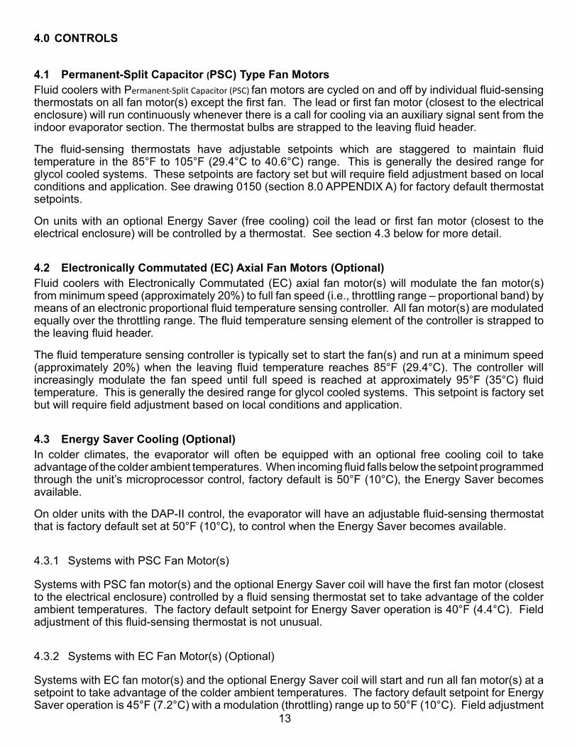
4.1 Permanent-Split Capacitor (PSC) Type Fan MotorsFluid coolers with Permanent-Split Capacitor (PSC) fan motors are cycled on and off by individual fluid-sensing thermostats on all fan motor(s) except the first fan. The lead or first fan motor (closest to the electrical enclosure) will run continuously whenever there is a call for cooling via an auxiliary signal sent from the indoor evaporator section. The thermostat bulbs are strapped to the leaving fluid header.
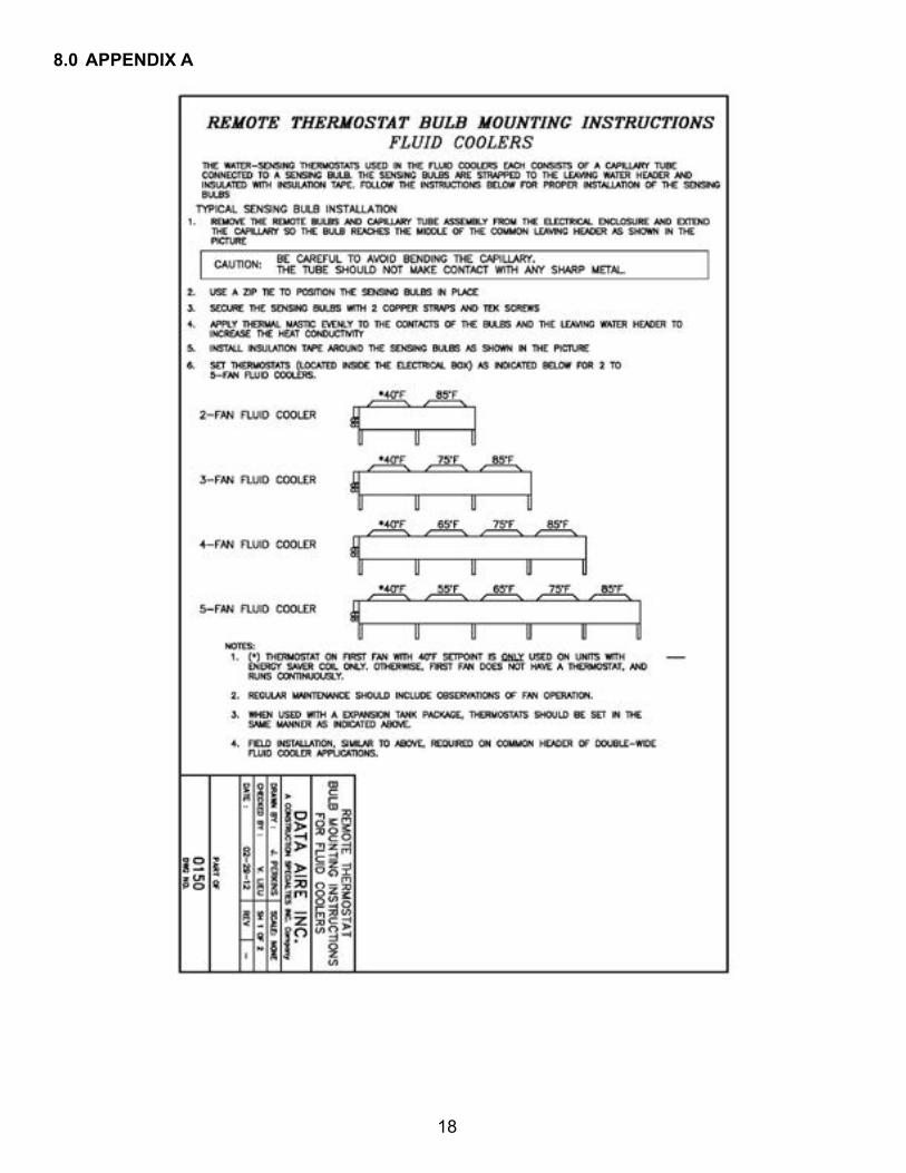
The fluid-sensing thermostats have adjustable setpoints which are staggered to maintain fluid temperature in the 85°F to 105°F (29.4°C to 40.6°C) range. This is generally the desired range for glycol cooled systems. These setpoints are factory set but will require field adjustment based on local conditions and application. See drawing 0150 (section 8.0 APPENDIX A) for factory default thermostat setpoints.
On units with an optional Energy Saver (free cooling) coil the lead or first fan motor (closest to the electrical enclosure) will be controlled by a thermostat. See section 4.3 below for more detail.
4.2 Electronically Commutated (EC) Axial Fan Motors (Optional)Fluid coolers with Electronically Commutated (EC) axial fan motor(s) will modulate the fan motor(s) from minimum speed (approximately 20%) to full fan speed (i.e., throttling range – proportional band) by means of an electronic proportional fluid temperature sensing controller. All fan motor(s) are modulated equally over the throttling range. The fluid temperature sensing element of the controller is strapped to the leaving fluid header.
The fluid temperature sensing controller is typically set to start the fan(s) and run at a minimum speed (approximately 20%) when the leaving fluid temperature reaches 85°F (29.4°C). The controller will increasingly modulate the fan speed until full speed is reached at approximately 95°F (35°C) fluid temperature. This is generally the desired range for glycol cooled systems. This setpoint is factory set but will require field adjustment based on local conditions and application.
4.3 Energy Saver Cooling (Optional)In colder climates, the evaporator will often be equipped with an optional free cooling coil to take advantage of the colder ambient temperatures. When incoming fluid falls below the setpoint programmed through the unit’s microprocessor control, factory default is 50°F (10°C), the Energy Saver becomes available.
On older units with the DAP-II control, the evaporator will have an adjustable fluid-sensing thermostat that is factory default set at 50°F (10°C), to control when the Energy Saver becomes available.
4.3.1 Systems with PSC Fan Motor(s)
Systems with PSC fan motor(s) and the optional Energy Saver coil will have the first fan motor (closest to the electrical enclosure) controlled by a fluid sensing thermostat set to take advantage of the colder ambient temperatures. The factory default setpoint for Energy Saver operation is 40°F (4.4°C). Field adjustment of this fluid-sensing thermostat is not unusual.
4.3.2 Systems with EC Fan Motor(s) (Optional)
Systems with EC fan motor(s) and the optional Energy Saver coil will start and run all fan motor(s) at a setpoint to take advantage of the colder ambient temperatures. The factory default setpoint for Energy Saver operation is 45°F (7.2°C) with a modulation (throttling) range up to 50°F (10°C). Field adjustment

14
of the electronic controller is not unusual.
NOTE: Every application will have a different ambient temperature and indoor heat load/air distribution profile. Therefore it is not possible to dictate the exact fluid temperature setpoint. Field adjustments are typical to allow fine-tuning to specific conditions.
It is desirable to use the Energy Saver mode as much as possible. However, fluid temperature that is cold can cause excessive dehumidification and coil sweating. Fluid temperature that is too high can cause the indoor space temperature to rise. This can cause the indoor evaporator control to lock out the Energy Saver mode for one (1) hour while it reverts to compressor cooling. Adjust the setpoints of the thermostats to allow the maximum free cooling time. Over cooling and under cooling the fluid should be avoided.

15
5.0 WARRANTY
NOTE: See separate warranty certificate and registration card that is supplied with each unit as part of the paperwork package.
6.0 PREVENTIVE MAINTENANCE
The operating life of the fluid cooler can be extended by following a simple preventive maintenance schedule. This schedule will reduce the possibility of failure of components and unnecessary malfunction of the system. Although the service technicians must be thoroughly familiar with the special design features of this equipment before attempting any service or repair, an experienced technician can perform certain simple maintenance functions to ensure normal, trouble-free operation.
6.1 Maintenance Functions
Monthly Inspect fluid cooler for obstruction to the inlet air side of the coil
Inspect the motor/fan blade assemblies to ensure the bearings are free and the motor mounts and fan(s) are secure
Bleed air from the systemSeasonally Inspect electrical components for loose wire connections
Inspect contactor contacts for pitting
Check glycol solution level in the system
Inspect fan motor(s)
In the winter, do not allow snow to accumulate or build-up around the sides or underneath the coil
Bi-Annually Check the glycol solution inhibitors. Flush as necessary
Clean the fluid cooler coil of all debris that could restrict air flow
Annually Check the glycol system for leaks and corrosion

16
6.2 Coil CleaningKeeping the outdoor coils clean is an important factor in maintaining peak efficiency, reliability and long life of the equipment. It is much easier to keep up on frequent cleanings rather than wait until heavy build up has occurred which may create head pressure problems with the evaporator units.
6.2.1 When to Clean
Normal conditions typically dictate cleaning twice a year, spring and fall. On-site or area conditions such as cottonwood trees, construction, etc., can increase cleaning frequency. On your standard monthly preventive maintenance schedule, a visual inspection of the coil is recommended to monitor conditions.
6.2.2 What to Use
The best overall coil cleaner to use is plain water. If the coil has been maintained and cleaned at regular intervals, water is sufficient to remove dirt and debris from the fins. Heavy build up on the exterior of the fins can be removed with a brush. Water pressure from a garden hose and sprayer usually works well. If a pressure washer is used, make sure the equipment is set to a lower pressure setting and that the nozzle is set to the fan spray, not stream. Otherwise, damage to the fins could result. If a cleaner is required, we recommend a non-acidic type cleaner be used. Acid-type cleaners can be aggressive to the coil fins as well as surrounding areas. Many sites do not allow the use of acidic cleaners for environmental reasons.
6.2.3 How to Clean
The absolute best way to clean coils is from the inside out. This requires disconnecting the power supply before working on the unit. The fan guards and fan blades must be removed to gain access to the coil surface. The sprayer can then be worked across the coil using the water/cleaning solution, pushing the dirt and debris out the bottom of the coil. Although this does extend the time involved, the results are well worth it. This method should be used at least once a year. Spraying the coil from the outside repeatedly can push a majority of the dirt to the inner section of the fins and continue to restrict air flow. Keep in mind you may not have the luxury of shutting the unit(s) down for an extended time. A pre-scheduled shutdown with the operator may be in order. If you are using a cleaner along with the spraying process, follow recommended manufacturer instructions and be sure to rinse the coil thoroughly. Any residue left on the coil can act as a magnet to dirt.
Reinstall and secure the fan blades and fan guards after the cleaning is finished. Last, reconnect the power supply to the unit.

17
7.0 CONTACT DATA AIRE
Address: Data Aire, Inc.
230 West Blueridge Avenue
Orange, CA 92865
Telephone: 714-921-6000
800-347-AIRE (2473) Toll Free
Fax: 714-921-6010 Main
714-921-6011 Engineering
714-921-6022 Parts Sales
E-mail: [email protected]
Web Site: www.dataaire.com
Job/Unit Information:
Data Aire Job Number: ___________________________________
Evaporator Serial Number: ________________________________
Evaporator Model Number: _______________________________
Fluid Cooler Serial Number: _______________________________
Fluid Cooler Model Number: ______________________________
Installing Contractor: ____________________________________
Date installed: _______ / _____ / 20_____
18
8.0 APPENDIX A

19
APPENDIX A
20
INDEX Air flow .................................................. 5 Transportation damage.........................5
Air vents................................................ 7 Valves....................................................7
Antifreeze ....................................... 9, 10 Vibration................................................6
Clearance ............................................. 5 Volume..................................................9
Closed-circuit design ............................ 4 Warranty......................................5, 7, 15
Coil ................................... 5, 6, 7, 13, 15 Wiring diagrams..............................5, 12
Concrete pads ...................................... 6
Controller ...................................... 12, 13
Electronic temperature controller.......... 5
Electronically Commutated ................. 13
External damage .................................. 5
Fluid Cooler ................................ 5, 9, 17
Free cooling ........................................ 13
Freezing............................................ 5, 9
Hydrometers ......................................... 9
Inspect .................................................. 5
Internal damage.................................... 5
Leakage ................................................ 7
Modulate ............................................. 13
Mounting ............................................... 5
Noise .................................................... 6
Obstructions ......................................... 5
Optional ........................................ 11, 13
Permanent-Split Capacitor ................. 13
Pre-mixed ........................................... 10
Preventive maintenance schedule...... 15
Start-up sheet ....................................... 5
Support ............................................. 5, 6
Thermostats.................................... 4, 13


Data Aire, Inc.230 W. BlueRidge Avenue
Orange, CA 92865800-347-2473
ISO 9001-2008 CertifiedA Member of the C/S Group of Companies
Creating Products That Make Building Better
FluidCoolerIOM 01-2016