Embed Size (px)
Citation preview
Fluid Basics
Concept and Theory Training
Introduction ........................................... 1Overview .............................................................. 1How to use this module ........................................... 1
Basic Fluid Terminology.......................... 3Learning Objectives ................................................3Fluid, Liquid, and Material ................................... 3Evaporation and Sublimation ................................ 3Suspensions and Solutions....................................... 4Settling Out: a Common Problem ........................... 4
Fluid Properties ...................................... 9Learning Objectives ................................................9Viscosity ................................................................. 9Centipoise: Standard Unit of Viscosity................... 10Measuring Viscosity.............................................. 10Specific Gravity.................................................... 13Density ................................................................ 13Surface Tension .................................................... 13Shear ................................................................... 14Shear Rate (or Rate of Shear) ............................... 14Shear Stress .......................................................... 15Relationship Between Viscosity and Shear ............. 15Newtonian Fluids ................................................ 15Non-Newtonian Fluids........................................ 16Plastic .................................................................. 16Pseudoplastic ........................................................ 17Dilatant .............................................................. 18Flow and Frictional Pressure Loss......................... 19Laminar Flow and Turbulent Flow ..................... 20Pressure................................................................ 21Measuring Pressure .............................................. 22Gauge and Absolute Pressure Scales ....................... 23
Factors to Consider When Selecting Internal System Materials..................... 28
Learning Objectives ..............................................28Corrosiveness of Fluids ......................................... 28Passivation .......................................................... 30Chemical Compatibility of Fluids and Pump Materials ............................................ 30Abrasiveness of Fluids........................................... 31
Fluid Basicsi
Table of Contents
Graco, Inc.P.O. Box 1441Minneapolis, MN 55440-1441
©1995 Graco Inc. Form No. 321-026 7/95 Printed in U.S.A.
Introduction
Welcome to Fluid Basics, a learning module in Graco’s concept and theory sales training series. Yourunderstanding of the information in this module provides the basis for further study on specific Graco products. Your ability to successfully promote and sell Graco products depends in part on how well you learn the basics and then apply this knowledge to addressing your customers’ needs.
While this curriculum best fits the requirements of Graco and distributor sales people, it will also ben-efit anyone whose job function depends on knowledge of Graco’s products.
OverviewTo be effective in the marketplace, Graco and distributor sales people must understand the basic termsand concepts related to the fluids that move through Graco products. This module, Fluid Basics, intro-duces those basic terms and concepts and shows how they relate to the day-to-day world of Gracoproduct specification and sales.
How to Use this ModuleThe basic concept and theory curriculum consists of a series of self-study modules. As the term self-study implies, you work through the materials on your own at a comfortable pace. Plan sufficient time(approximately 30 minutes) to complete at least one section of a module in a working session.
This module combines a variety of features to make the learning process convenient and productive:
• Learning objectives
• Text
• Charts, illustrations
• Progress checks
• Additional resources
Fluid Basics 1
Learning ObjectivesEach section of material offers a set of learning objectives. Read the objectives and use them to guideyou to the most important concepts. After you finish each section and before you complete theprogress check, reread the objectives to confirm that you understand the key concepts.
TextDefinitions, examples, and explanations comprise the learning module text. Read it carefully andreturn for review if necessary.
Charts, IllustrationsAn important element of any instruction is visualizing the concepts. This module contains graphicsand illustrations to enhance the text material and aid your learning. Where appropriate, the modulealso contains charts that help you organize or summarize information.
Progress ChecksProgress checks are self-tests that provide reinforcement and confirm your understanding of important topics. After completing each section of the module, return to review the objectives,and then work through each of the progress check items. Upon completion, check your answersagainst those provided. If you answered any incorrectly, return to the text and reread the pertinentinformation.
Additional ResourcesThis module may refer you to other documents or sources that expand on the concepts covered in the module. The reference will include the name of the source and how you can obtain it.
Fluid Basics2
Basic Fluid Terminology
Learning ObjectivesTo discuss your customers’ needs and show how Graco systems can satisfy those needs, you mustunderstand some basic terms and concepts about fluids. This section defines those terms and showsyou how they fit into your day-to-day work. After completing this section, you will be able to:
• State definitions of the most basic terms relating to the fluids commonly moved through Graco products.
• Explain every-day Graco usage of those terms.
Fluid, Liquid, and MaterialIn the most precise dictionary definition, a liquid is a substance wherein molecules move freely amongthemselves, but do not tend to separate like those of a gas. Similarly, in the most precise terms, a fluid isany gas or liquid that may be caused to flow.
But at Graco—and throughout the remainder of this training module—we commonly use fluid instead of liquid. This is a matter of practicality since the fluids that commonly move through Graco products are liquids. The major types of fluids commonly moved through Graco products are:• Paints and other coatings • Adhesives • Sealants • Inks• Solvents and thinners • Fuels • Lubricants
At Graco and in industry at large, the word material is used in two different ways. We refer to the hugerange of solid substances from which products are manufactured as materials. For example, you mighthear an engineer employed by your customer say, “We need the materials in the body of this pump to be stainless steel and brass.” But we also use material as another word—along with fluid and liquid—to refer to the substances moved through Graco products. For example,you might hear your customer say, “I need to pump about 100 gallons (379 liters) of material a day.”Typically, we reserve this latter usage of material for the liquids being pumped.
Evaporation and SublimationEvaporation is the process of conversion of a fluid to a gas. Sublimation is the process of conversion ofa solid directly to a gas with no liquid phase in between. Both of these conversions result from heatinga substance or from reducing the pressure on a substance.
Fluid Basics 3
Suspensions and SolutionsA suspension is a mixture of a fluid and small solid particles. Paint is a suspension commonly moved through Graco products. The suspended particles in paints are usually pigments (coloring agents) and fillers that change the consistency and adhesion characteristics of the paint. If allowed to remain at rest, gravity will cause the particles in a suspension to settle to the bottom of the container.
A suspension is fundamentally different from a solution. In a solution, the mixing of two substancestakes place at the molecular level and is completely homogeneous throughout. A common example ofa solution is salt water. The solid in a solution is said to be dissolved. Dissolved material will not settleto the bottom of the container, no matter how long it is left at rest. Only chemical processes, such asevaporation of the fluid, will cause the solid to “come out of solution.”
Settling Out: a Common Problem The phenomenon referred to above—the settling out of solids in a suspension—is a problem with themost common type of fluid moved in Graco systems: paint. If we do not prevent settling, two kinds ofproblems will result. First, solid paint particles may clog filters and other system components; this iscommonly referred to as packing out. Second, settling may lead to application problems. For example,in the automotive industry, settling out of paints has led to problems of color-matching from one partof a car to another.
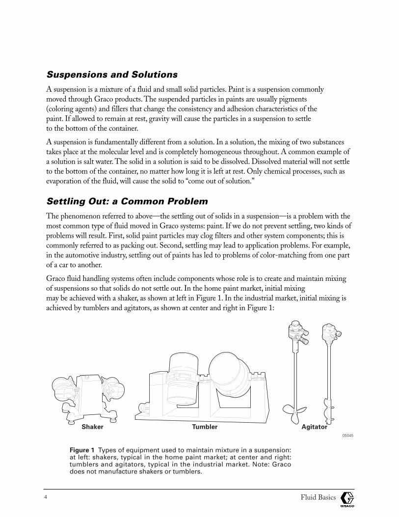
Graco fluid handling systems often include components whose role is to create and maintain mixingof suspensions so that solids do not settle out. In the home paint market, initial mixing may be achieved with a shaker, as shown at left in Figure 1. In the industrial market, initial mixing isachieved by tumblers and agitators, as shown at center and right in Figure 1:
Figure 1 Types of equipment used to maintain mixture in a suspension:at left: shakers, typical in the home paint market; at center and right:tumblers and agitators, typical in the industrial market. Note: Gracodoes not manufacture shakers or tumblers.
Fluid Basics4
Shaker Agitator
05045
Tumbler

In industrial systems, once a homogeneous mixture is achieved, that homogeneity may be maintainedwith agitators, such as the types shown in Figure 1. Or the fluid may be constantly pumped throughthe system to maintain the suspension. Such a system is called a recirculating system. Figure 2 shows arecirculating system:
Figure 2 A Graco recirculating system; fluid is kept in constant motion to prevent settling of solids.
Fluid Basics 5
05030
Progress Check
Directions: After answering the following questions, compare your answers with those provided in theanswer key following this progress check. If you respond to any items incorrectly, return to the text andreview the appropriate topics.
1. What term do we commonly use at Graco instead of liquid? ____________________________ .
2. Name five of the seven major types of fluids that are moved in Graco systems:
______________________________________________________________________________
______________________________________________________________________________
______________________________________________________________________________
______________________________________________________________________________
3. At Graco, we often use the word material to refer to a fluid moving through a Graco system.What is the other common Graco usage of material?
______________________________________________________________________________
4. Select the statement that correctly defines the difference between a suspension and a solution:
a. In a suspension, gravity can separate the solid from the fluid, but in a solution, only chemicalprocesses will separate the two components.
b. In a solution, gravity can separate the solid from the fluid, but in a suspension, only chemicalprocesses will separate the two components.
c. A suspension is a mixture of a solid and a fluid, while a solution is a chemical compound.
d. A solution contains larger particles than a suspension.
5. Explain the term, “packed out.”
______________________________________________________________________________
______________________________________________________________________________
6. Select all devices that might be used to maintain a suspension once it had been achieved:
a. Tumblers
b. Shakers
c. Pumps
d. Agitators
Fluid Basics6
For items 7 through 10, match the terms with their definitions:
Terms
a. Sublimation
b. Suspension
c. Solution
d. Evaporation
Definitions
___ 7. The process of transforming a liquid to a gas.
___ 8. A mixture of solid particles and a fluid.
___ 9. A combination at the molecular level of a fluid and a solid.
___10. The process of transforming a solid directly to a gas with no intermediary liquid phase.
Fluid Basics 7
Answers to Progress Check
1. Fluid
2. Paints and coatings, adhesives, sealants, inks, solvents and thinners, fuels, lubricants
3. A solid substance from which products are manufactured.
4. a. In a suspension, gravity can separate the solid from the fluid, but in a solution, only chemical processes will separate the two components.
5. “Packed out” is a term used to describe a clog in a system caused by solid particles that have set-tled out of a fluid.
6. After a suspension has been achieved, pumps and agitators could be used to maintain it.
7. d. Evaporation is the process of transforming a liquid to a gas.
8. b. Suspension is a mixture of solid particles and a fluid.
9. c. Solution is a combination at the molecular level of a fluid and a solid.
10. a. Sublimation is the process of transforming a solid directly to a gas with no intermediary liquid phase.
Fluid Basics8
Fluid Properties
Learning ObjectivesTo correctly and reliably recommend Graco products to your customers, you need to understand theproperties of the fluids that will be moving through those products. This section introduces you to those properties. After completing this section, you will be able to:
• State the basic properties of fluids, including terms of expression and methods of measurement.
• Explain how to use data on each of the basic properties of fluids to help specify Graco products for your customers.
• Distinguish among the various flow behaviors of fluids and describe how these differences are relevant to Graco products.
ViscosityViscosity is the resistance of a fluid to flowing. Thus, the more a fluid resists flowing, the higher its vis-cosity is said to be. For example, axle grease is much more viscous than motor oil and motor oil is much more viscous than gasoline. To move a fluid, you must overcome its viscosity. And since thepurpose of Graco products is to move fluids, it is safe to say that viscosity is the single most importantproperty of a fluid to consider when you are recommending Graco products.
The viscosity of a given fluid will vary predictably with changes in many factors. The most importantof these factors is temperature. In fact, to be meaningful, a viscosity rating must always be stated inconjunction with the temperature of the fluid. The viscosities of virtually all fluids decrease as theirtemperatures increase.
When fluids are in motion—as they are sooner or later in all Graco systems—viscosity is also directlyrelated to another factor: shear. Shear is the slipping of one layer of a fluid relative to an adjacent layer.To visualize this concept, think of fluid layers that are just one molecule thick; imagine the drag thatresults as the layers of molecules move past each other. Shear is expressed as the relationship amongseveral factors, including the force imparted to one surface of a fluid, the resulting velocity of that layer,and the thickness across the layers. Shear and its relationship to viscosity are discussed in more detaillater in this module.
Fluid Basics 9
Centipoise: Standard Unit of Viscosity
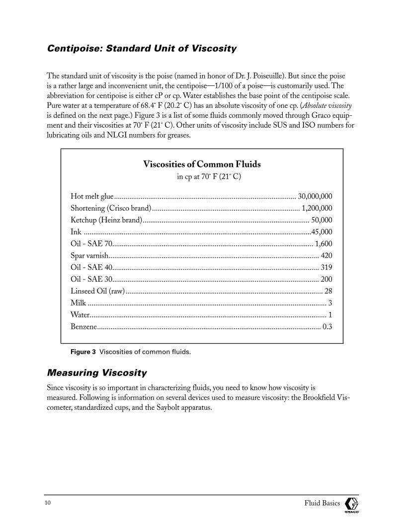
The standard unit of viscosity is the poise (named in honor of Dr. J. Poiseuille). But since the poise is a rather large and inconvenient unit, the centipoise—1/100 of a poise—is customarily used. Theabbreviation for centipoise is either cP or cp. Water establishes the base point of the centipoise scale.Pure water at a temperature of 68.4˚ F (20.2˚ C) has an absolute viscosity of one cp. (Absolute viscosityis defined on the next page.) Figure 3 is a list of some fluids commonly moved through Graco equip-ment and their viscosities at 70˚ F (21˚ C). Other units of viscosity include SUS and ISO numbers forlubricating oils and NLGI numbers for greases.
Viscosities of Common Fluidsin cp at 70˚ F (21˚ C)
Hot melt glue................................................................................................ 30,000,000Shortening (Crisco brand).............................................................................. 1,200,000Ketchup (Heinz brand)........................................................................................ 50,000Ink ........................................................................................................................45,000Oil - SAE 70.......................................................................................................... 1,600Spar varnish............................................................................................................... 420Oil - SAE 40............................................................................................................. 319Oil - SAE 30............................................................................................................. 200Linseed Oil (raw)........................................................................................................ 28Milk .............................................................................................................................. 3Water............................................................................................................................. 1Benzene...................................................................................................................... 0.3
Figure 3 Viscosities of common fluids.
Measuring ViscositySince viscosity is so important in characterizing fluids, you need to know how viscosity is measured. Following is information on several devices used to measure viscosity: the Brookfield Vis-cometer, standardized cups, and the Saybolt apparatus.
Fluid Basics10
Absolute Viscosity
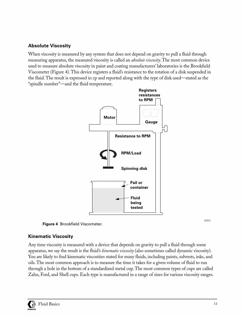
When viscosity is measured by any system that does not depend on gravity to pull a fluid throughmeasuring apparatus, the measured viscosity is called an absolute viscosity. The most common deviceused to measure absolute viscosity in paint and coating manufacturers’ laboratories is the BrookfieldViscometer (Figure 4). This device registers a fluid’s resistance to the rotation of a disk suspended inthe fluid. The result is expressed in cp and reported along with the type of disk used—stated as the“spindle number”—and the fluid temperature.
Figure 4 Brookfield Viscometer.
Kinematic Viscosity
Any time viscosity is measured with a device that depends on gravity to pull a fluid through someapparatus, we say the result is the fluid’s kinematic viscosity (also sometimes called dynamic viscosity).You are likely to find kinematic viscosities stated for many fluids, including paints, solvents, inks, andoils. The most common approach is to measure the time it takes for a given volume of fluid to runthrough a hole in the bottom of a standardized metal cup. The most common types of cups are calledZahn, Ford, and Shell cups. Each type is manufactured in a range of sizes for various viscosity ranges.
Fluid Basics 11
Motor
RPM/Load
Spinning disk
Gauge
Registers
resistances
to RPM
Resistance to RPM
05031
Pail or
container
Fluid
being
tested
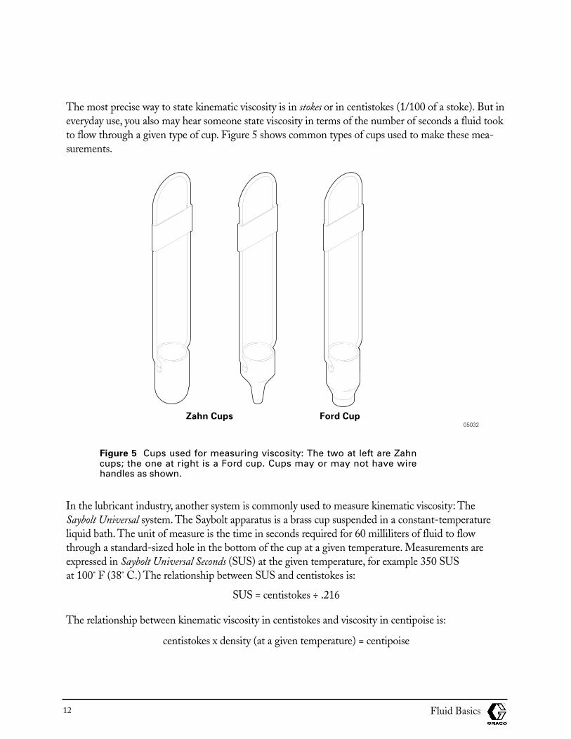
The most precise way to state kinematic viscosity is in stokes or in centistokes (1/100 of a stoke). But ineveryday use, you also may hear someone state viscosity in terms of the number of seconds a fluid tookto flow through a given type of cup. Figure 5 shows common types of cups used to make these mea-surements.
Figure 5 Cups used for measuring viscosity: The two at left are Zahncups; the one at right is a Ford cup. Cups may or may not have wire handles as shown.
In the lubricant industry, another system is commonly used to measure kinematic viscosity: The Saybolt Universal system. The Saybolt apparatus is a brass cup suspended in a constant-temperatureliquid bath. The unit of measure is the time in seconds required for 60 milliliters of fluid to flowthrough a standard-sized hole in the bottom of the cup at a given temperature. Measurements areexpressed in Saybolt Universal Seconds (SUS) at the given temperature, for example 350 SUS at 100˚ F (38˚ C.) The relationship between SUS and centistokes is:
SUS = centistokes ÷ .216
The relationship between kinematic viscosity in centistokes and viscosity in centipoise is:
centistokes x density (at a given temperature) = centipoise
Fluid Basics12
Zahn Cups Ford Cup05032
Specific GravityThe specific gravity of a liquid or solid—abbreviated s.g.—is defined as the ratio of the weight of agiven volume of the material to the weight of an equal volume of water:
weight of a given volume of a materials.g. =
weight of an equal volume of water
Example; English measurements are figured using lbs/ft3, metric measurements are figured usinggrams/cc. Since s.g. is a ratio no configuration is needed. The weight of a cubic foot of water is 62.4pounds. If one cubic foot of a certain paint weighs 80 pounds, its specific gravity is:
80 / 62.4 = 1.3
The specific gravities of most paints and other surface coatings are between 1 and 1.5. You must specify specialized heavy-duty equipment for moving fluids with specific gravities above 2.
You will need to determine the pressure loss due to specific gravity of a fluid whenever your customermust pump a fluid upward through a Graco system. Due to gravity, more and more pressure will belost as the fluid is pumped higher and higher. This pressure loss will be proportional to the fluid’s specific gravity:
English - pressure loss/vertical foot = s.g. x 0.44 psi
Metric - pressure loss/vertical meter = s.g. x 0.1 bar
Take the paint mentioned as an example. Its specific gravity is 1.3. Therefore, its pressure loss per vertical foot will be:
1.3 x 0.44 = 0.57 psi (.04 bar)
Imagine that we are evaluating the possibility of using a siphon-feed system that works at atmosphericpressure, or app. 14.7 psi (1.0 bar)(typical value for a siphon-feed system) to pump this paint up 20feet, (6.1 meters) where the paint must be sprayed. Applying the pressure loss formula, we find:
20 feet (6.1 meters) x 0.57 psi (.04 bar) / vertical foot = 11.4 psi (.79 bar)
If we used this system with this paint we would be able to siphon feed, because atmospheric pressure isgreater than the pressure drop in the siphon tube 14.7 - 11.4 = 3.3 psi (1.0 - .79 = .21 bar).
DensityThe density of a fluid (or any other material) is defined as its weight per unit volume, expressed ingrams per cubic centimeter or pounds per cubic foot. For example, as stated earlier, the density of wateris 62.4 lbs/ft3 (1 gram/cc).
Fluid Basics 13
Surface TensionSurface tension, a normal result of the molecular structure of a fluid, is a force that tends to minimizeand constrict the surface of a fluid. Most surface tension-related problems will arise in connection withpaints and other coatings. The most common of these problems is the formation of an uneven coatingwhen surface tension of the paint is greater than that of the substrate. In most cases, this is not a problem you can solve; it must be referred to the paint supplier who may recommend a lower-surface tension paint or may actually change the formulation of the paint to lower its surface tension.
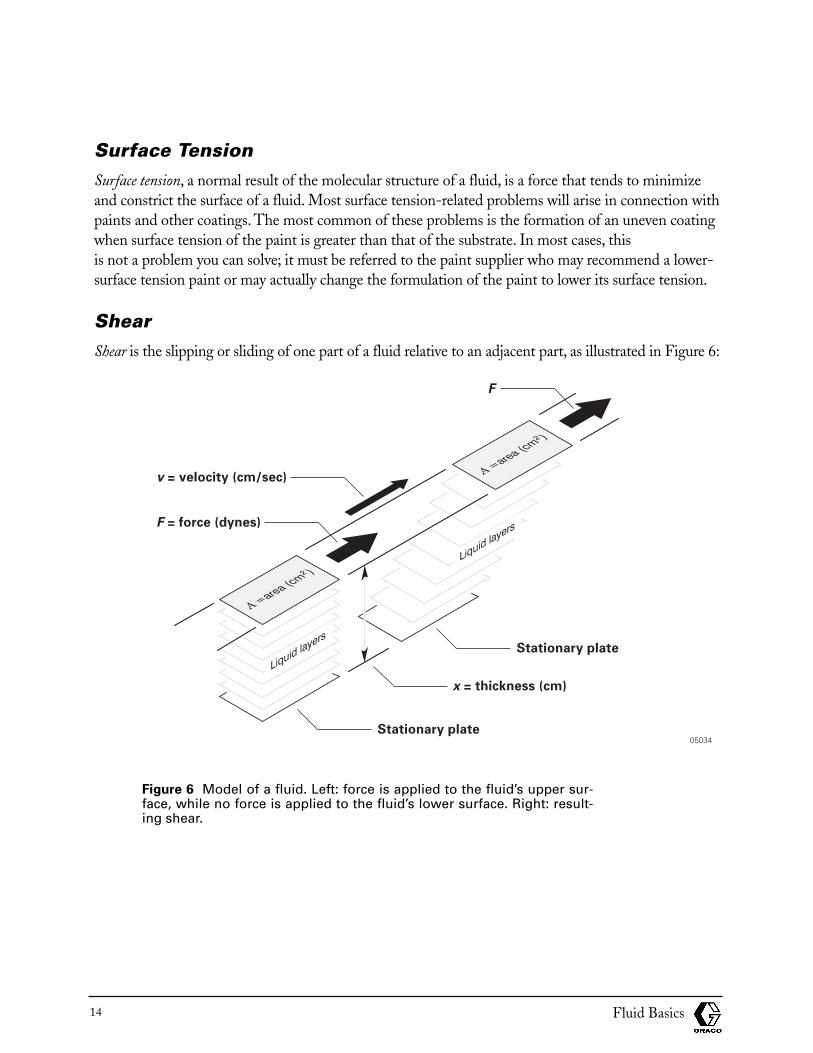
ShearShear is the slipping or sliding of one part of a fluid relative to an adjacent part, as illustrated in Figure 6:
Figure 6 Model of a fluid. Left: force is applied to the fluid’s upper sur-face, while no force is applied to the fluid’s lower surface. Right: result-ing shear.
Fluid Basics14
v = velocity (cm/sec)
F = force (dynes)
x = thickness (cm)
F
Stationary plate
Stationary plate05034
Shear Rate (or Rate of Shear)Shear rate is the rate of slip within a flowing fluid. The average or mean shear rate of a fluid in a pipe ortube is the average velocity divided by the radius of the tube:
average velocityshear rate =
radius
Shear StressShear stress is the term used to refer to any force that tends to impart motion to a fluid. Stirring andpumping are typical forces that impart shear stress to fluids. Shear stress is expressed as a specifiedforce exerted on a specified area:
forceshear stress = area
Relationship Between Viscosity and ShearThe relationship between viscosity, shear stress, and shear rate is expressed by the following formula:
shear stressviscosity = shear rate
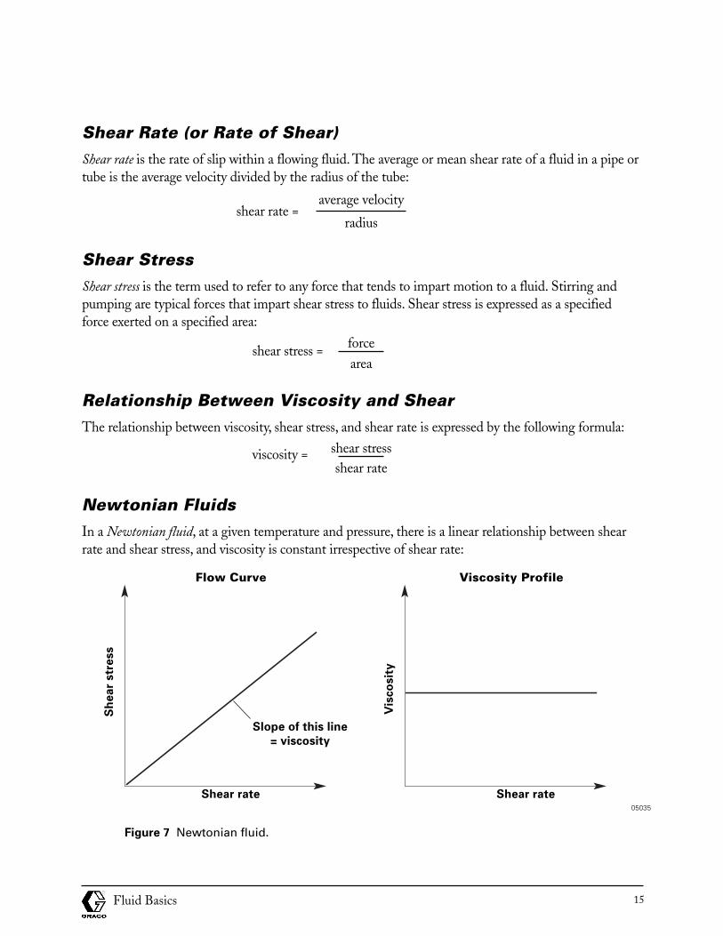
Newtonian FluidsIn a Newtonian fluid, at a given temperature and pressure, there is a linear relationship between shearrate and shear stress, and viscosity is constant irrespective of shear rate:
Figure 7 Newtonian fluid.
Fluid Basics 15
Flow Curve Viscosity Profile
Slope of this line
= viscosity
Shear rate
Sh
ea
r str
ess
Vis
co
sit
y
Shear rate05035
Remember that, as stated on page 14 and as expressed in Figure 7, the viscosity of a fluid may bederived by dividing shear stress by shear rate.
Newtonian fluids are named after Sir Isaac Newton, who first deduced these relationships. Examplesof Newtonian fluids include water and most mineral oils.
Non-Newtonian FluidsThe viscosities of non-Newtonian fluids vary with shear rate. Therefore, it is misleading to state a singleviscosity for these fluids. Instead, the term apparent viscosity is used to describe a non-Newtonian’sviscous properties at a given shear rate. You will encounter three types of non-Newtonian fluids:
• Plastic
• Pseudoplastic
• Dilatant
Following are discussions and examples of each type of non-Newtonian fluid.
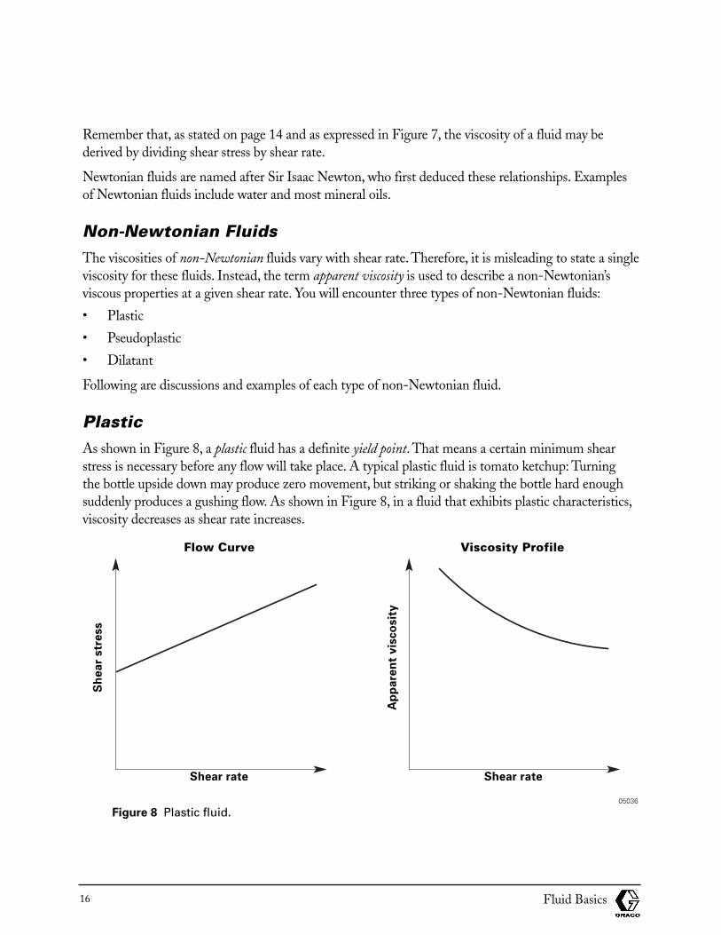
PlasticAs shown in Figure 8, a plastic fluid has a definite yield point. That means a certain minimum shearstress is necessary before any flow will take place. A typical plastic fluid is tomato ketchup: Turning the bottle upside down may produce zero movement, but striking or shaking the bottle hard enoughsuddenly produces a gushing flow. As shown in Figure 8, in a fluid that exhibits plastic characteristics,viscosity decreases as shear rate increases.
Figure 8 Plastic fluid.
Fluid Basics16
Flow Curve Viscosity Profile
Shear rate
Sh
ea
r str
ess
Ap
pa
ren
t v
isco
sit
y
Shear rate
05036
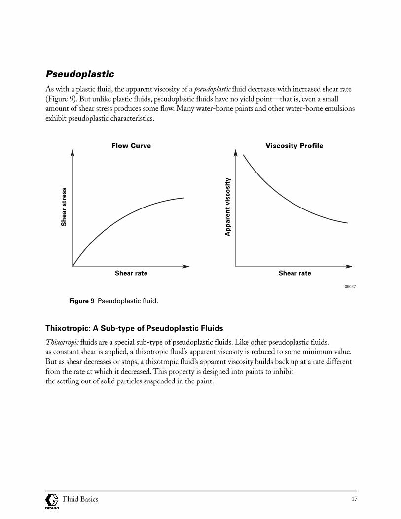
PseudoplasticAs with a plastic fluid, the apparent viscosity of a pseudoplastic fluid decreases with increased shear rate(Figure 9). But unlike plastic fluids, pseudoplastic fluids have no yield point—that is, even a smallamount of shear stress produces some flow. Many water-borne paints and other water-borne emulsionsexhibit pseudoplastic characteristics.
Figure 9 Pseudoplastic fluid.
Thixotropic: A Sub-type of Pseudoplastic Fluids
Thixotropic fluids are a special sub-type of pseudoplastic fluids. Like other pseudoplastic fluids,as constant shear is applied, a thixotropic fluid’s apparent viscosity is reduced to some minimum value.But as shear decreases or stops, a thixotropic fluid’s apparent viscosity builds back up at a rate differentfrom the rate at which it decreased. This property is designed into paints to inhibit the settling out of solid particles suspended in the paint.
Fluid Basics 17
Flow Curve Viscosity Profile
Shear rate
Sh
ea
r str
ess
Ap
pa
ren
t v
isco
sit
y
Shear rate
05037
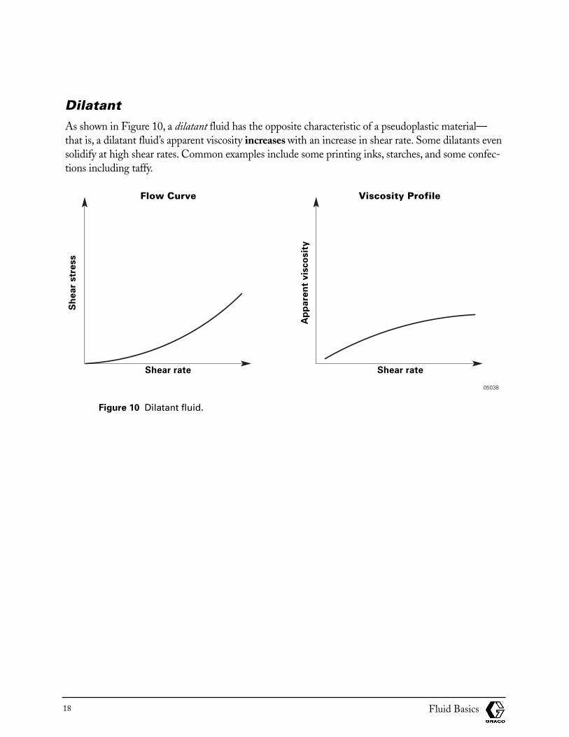
DilatantAs shown in Figure 10, a dilatant fluid has the opposite characteristic of a pseudoplastic material—that is, a dilatant fluid’s apparent viscosity increases with an increase in shear rate. Some dilatants evensolidify at high shear rates. Common examples include some printing inks, starches, and some confec-tions including taffy.
Figure 10 Dilatant fluid.
Fluid Basics18
Flow Curve Viscosity Profile
Shear rate
Sh
ea
r str
ess
Ap
pa
ren
t v
isco
sit
y
Shear rate
05038
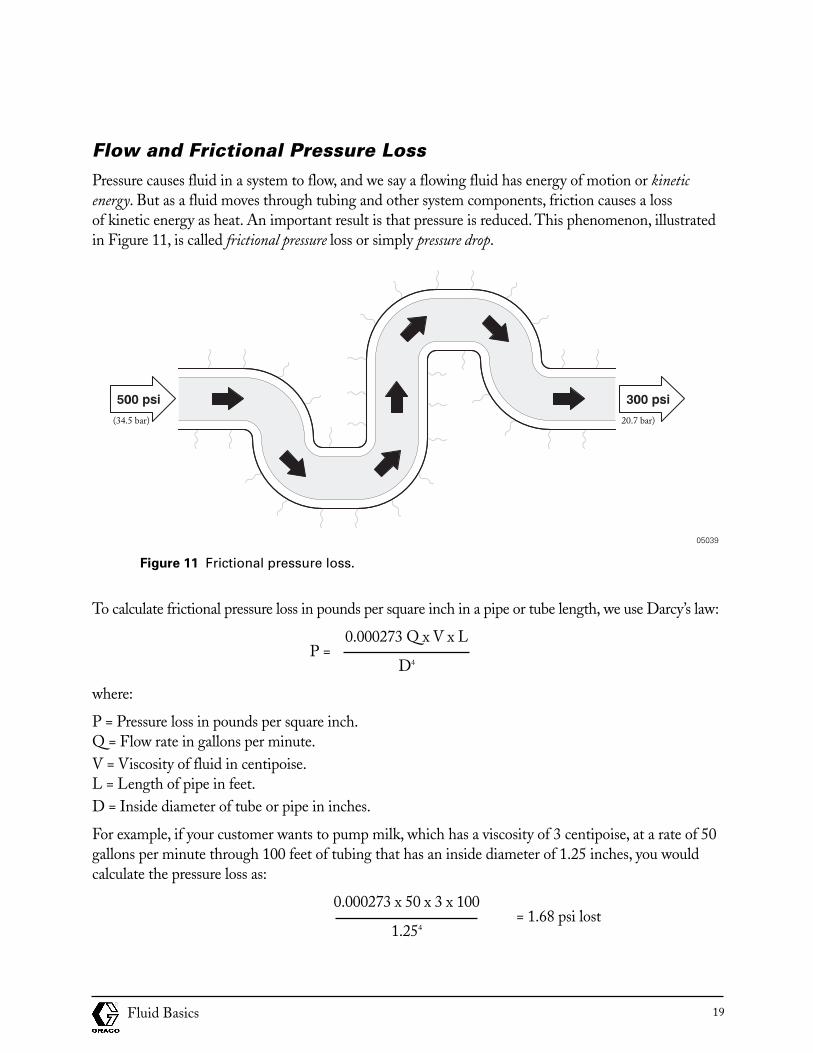
Flow and Frictional Pressure Loss Pressure causes fluid in a system to flow, and we say a flowing fluid has energy of motion or kineticenergy. But as a fluid moves through tubing and other system components, friction causes a loss of kinetic energy as heat. An important result is that pressure is reduced. This phenomenon, illustratedin Figure 11, is called frictional pressure loss or simply pressure drop.
Figure 11 Frictional pressure loss.
To calculate frictional pressure loss in pounds per square inch in a pipe or tube length, we use Darcy’s law:
0.000273 Q x V x LP =
D4
where:
P = Pressure loss in pounds per square inch.Q = Flow rate in gallons per minute.V = Viscosity of fluid in centipoise.L = Length of pipe in feet.D = Inside diameter of tube or pipe in inches.
For example, if your customer wants to pump milk, which has a viscosity of 3 centipoise, at a rate of 50gallons per minute through 100 feet of tubing that has an inside diameter of 1.25 inches, you wouldcalculate the pressure loss as:
0.000273 x 50 x 3 x 100= 1.68 psi lost
1.254
Fluid Basics 19
05039
(34.5 bar) 20.7 bar)
We also can calculate frictional pressure loss in kilograms per square centimeter, in which case Darcy’slaw takes this form:
69,300 Q x V x LP =
D4
where:
P = Pressure loss in kilograms per square centimeter.Q = Flow rate in liters per minute.V = Viscosity of fluid in poise.L = Length of pipe in meters.D = Inside diameter of tube or pipe in millimeters.
Note: Values of D4 for common sizes of tubing and piping are listed in the Graco Industrial Fluid Handling Products catalog.
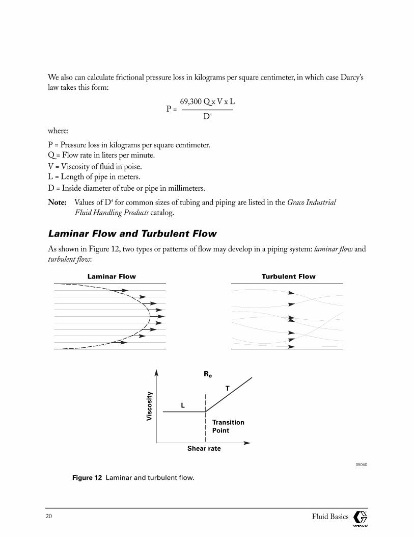
Laminar Flow and Turbulent Flow As shown in Figure 12, two types or patterns of flow may develop in a piping system: laminar flow andturbulent flow:
Figure 12 Laminar and turbulent flow.
Fluid Basics20
Laminar Flow Turbulent Flow
Shear rate
L
T
Transition
Point
Re
Vis
co
sit
y
05040
The idea of laminar flow is that molecules of a fluid act as though they were arranged in coherent layers—concentric layers if the fluid is in a tube. In turbulent flow, eddies or “whirlpools” in the flow pattern reduceflow and cause an increase in the apparent viscosity of the fluid.The point at which flow changes fromlaminar to turbulent is called the Reynolds Number, labeled Re in Figure 12.The Reynolds Number is cal-culated as follows:
velocity x tube length x s.g.Re =
viscosity
Most fluids change from laminar to turbulent flow when Re is between 2000 and 4000. You should knowabout Reynolds numbers because you may hear them discussed, but you also should know that Reynoldsnumbers are not significant in Graco systems because flow velocities in our systems are kept low enough to insure that Reynolds numbers are below 2000.Thus, turbulent flow very seldompresents a problem.
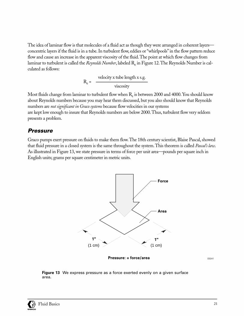
PressureGraco pumps exert pressure on fluids to make them flow.The 18th century scientist, Blaise Pascal, showedthat fluid pressure in a closed system is the same throughout the system.This theorem is called Pascal’s law.As illustrated in Figure 13, we state pressure in terms of force per unit area—pounds per square inch inEnglish units; grams per square centimeter in metric units.
Figure 13 We express pressure as a force exerted evenly on a given surfacearea.
Fluid Basics 21
Pressure: = force/area
Force
Area
1"1"
05041
(1 cm) (1 cm)
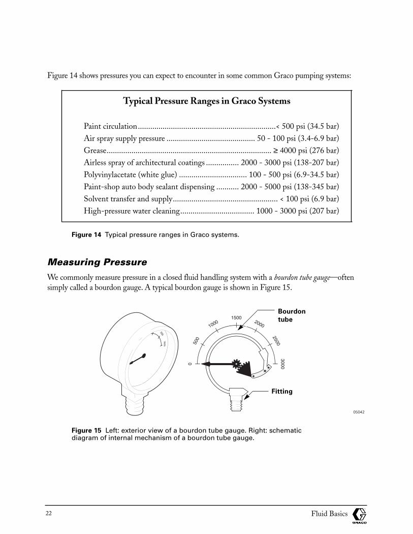
Figure 14 shows pressures you can expect to encounter in some common Graco pumping systems:
Typical Pressure Ranges in Graco Systems
Paint circulation...................................................................< 500 psi (34.5 bar)Air spray supply pressure ........................................... 50 - 100 psi (3.4-6.9 bar)Grease................................................................................ ≥ 4000 psi (276 bar)Airless spray of architectural coatings ................ 2000 - 3000 psi (138-207 bar)Polyvinylacetate (white glue) ................................. 100 - 500 psi (6.9-34.5 bar)Paint-shop auto body sealant dispensing ........... 2000 - 5000 psi (138-345 bar)Solvent transfer and supply................................................... < 100 psi (6.9 bar)High-pressure water cleaning.................................... 1000 - 3000 psi (207 bar)
Figure 14 Typical pressure ranges in Graco systems.
Measuring PressureWe commonly measure pressure in a closed fluid handling system with a bourdon tube gauge—oftensimply called a bourdon gauge. A typical bourdon gauge is shown in Figure 15.
Figure 15 Left: exterior view of a bourdon tube gauge. Right: schematicdiagram of internal mechanism of a bourdon tube gauge.
Fluid Basics22
Fitting
Bourdon
tube
05042
A bourdon gauge is inserted directly into a fluid handling system with a fitting so it registers whateverpressure is in the system. (Remember Pascal’s law: fluid pressure in a closed system is the samethroughout the system). As pressure in the system increases, the thin, curved bourdon tube inside thegauge straightens somewhat. Through gears, the straightening of the tube is converted to the motionof an indicator needle, which shows the system pressure.
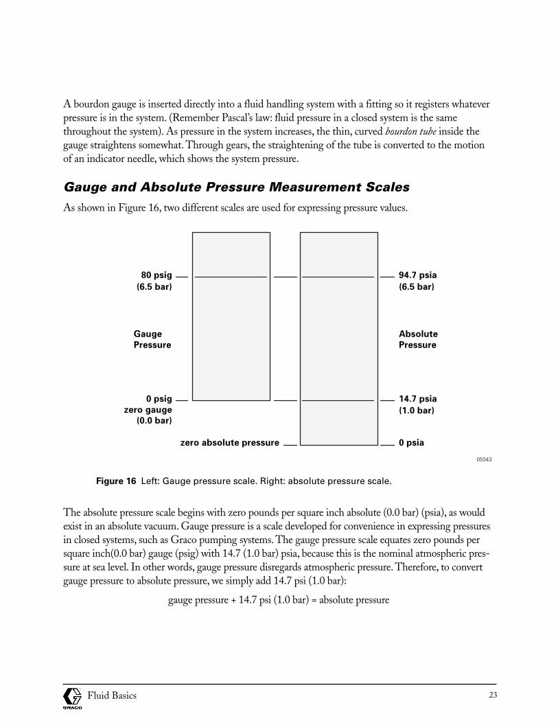
Gauge and Absolute Pressure Measurement ScalesAs shown in Figure 16, two different scales are used for expressing pressure values.
Figure 16 Left: Gauge pressure scale. Right: absolute pressure scale.
The absolute pressure scale begins with zero pounds per square inch absolute (0.0 bar) (psia), as wouldexist in an absolute vacuum. Gauge pressure is a scale developed for convenience in expressing pressuresin closed systems, such as Graco pumping systems. The gauge pressure scale equates zero pounds persquare inch(0.0 bar) gauge (psig) with 14.7 (1.0 bar) psia, because this is the nominal atmospheric pres-sure at sea level. In other words, gauge pressure disregards atmospheric pressure. Therefore, to convertgauge pressure to absolute pressure, we simply add 14.7 psi (1.0 bar):
gauge pressure + 14.7 psi (1.0 bar) = absolute pressure
Fluid Basics 23
0 psia
94.7 psia
(6.5 bar)
14.7 psia
(1.0 bar)
zero absolute pressure
80 psig
(6.5 bar)
0 psig
zero gauge
(0.0 bar)
Absolute
Pressure
Gauge
Pressure
05043
Progress Check
Directions: After answering the following questions, compare your answers with those provided in theanswer key following this progress check. If you respond to any items incorrectly, return to the text andreview the appropriate topics.
1. Select the most important property of a fluid to consider when you are recommending Graco products:
a. Specific gravity
b. Density
c. Viscosity
d. Surface tension
2. Select all of the following statements that are true about water:
a. Pure water at a temperature of 68.4˚ F (20.2˚ C) has an absolute viscosity of one cp.
b. The specific gravity of water is 1 centipoise.
c. The viscosity of water is 1 SSU.
d. The density of water is 62.4 pounds per cubic foot (1 gram/cc).
3. Select the devices that can be used to measure kinematic viscosity:
a. Zahn cups
b. Ford cups
c. Shell cups
d. Saybolt apparatus
e. Brookfield Viscometer
4. Select the types of fluids for which kinematic viscosity is commonly stated:
a. Paint
b. Oil
c. Taffy
d. Solvent
e. Adhesive
Fluid Basics24
For items 5 through 9, match the fluid type with its viscosity characteristics:
Fluid Type
a. Newtonian
b. Plastic
c. Pseudoplastic
d. Dilatant
e. Thixotropic
Viscosity Characteristics
___ 5. Viscosity is constant irrespective of shear rate.
___ 6. Apparent viscosity increases and decreases at different rates.
___ 7. Apparent viscosity increases with an increase in shear rate.
___ 8. Apparent viscosity decreases with an increase in shear rate.
___ 9. Has a yield point from which viscosity decreases with an increase in shear rate.
10. State Pascal’s law: _________________________________________________________________________________________________________________________________________
11. Which statement explains how a Bourdon Gauge works?
a. Pressure in the system presses on one side of a electrical capacitor, which is inserted in an electrical circuit so that current flow is inversely proportional to system pressure.
b. Pressure in the system straightens a metal strip, which is converted to the movement of aneedle indicator.
c. Pressure in the system forces a metal tube to straighten; the straightening is converted to themovement of a needle indicator.
Fluid Basics 25
For items 8 through 13, match the formulas with their desired results:
Terms
a. Shear stress
b. Shear rate
c. Vertical pressure drop
d. Centipoise
e. Absolute pressure
f. Frictional pressure loss (Darcy’s law)
Definitions
___12. centistokes x s.g. =
.000273 x Q x V x L 69,300 x Q x V x L___13. = P (English) = P (Metric)
D4 D4
___14. s.g. x 0.44 psi/foot = (s.g. x 0.1 bar/meter)
average velocity___15. =
radius
force___16. =
area
___17. gauge pressure + 14.7 psi = (1.0 bar)
Fluid Basics26
Answers to progress check
1. c. Viscosity
2. a. and d. are true:
Pure water at a temperature of 68.4˚ F (20.2˚ C) has an absolute viscosity of one cp.
The density of water is 62.4 pounds per cubic foot (1 gram/cc).
3. a. Zahn cups, b. Ford cups, c. Shell cups, and d. Saybolt apparatus, are all used to measure kinematicviscosity.
4. a. Paint, b. Oil, and d. Solvent
5. a. Newtonian: Viscosity is constant irrespective of shear rate.
6. e. Thixotropic: Apparent viscosity increases and decreases at different rates.
7. d. Dilatant: Apparent viscosity increases with an increase in shear rate.
8. c. Pseudoplastic: Apparent viscosity decreases with an increase in shear rate.
9. b. Plastic: Has a yield point from which viscosity decreases with an increase in shear rate.
10. Pascal’s law: Pressure in a closed system is the same throughout the system.
11. c. Pressure in the system forces a metal tube to straighten; the straightening is converted to the movement of a needle indicator.
12. d. Centistokes x s.g. = Centipoise
.000273 x Q x V x L 69,300 x Q x V x VXL13. f. = = Frictional pressure loss (Darcy’s law)
D4 D4
14. c. s.g. x 0.44 psi/foot = (s.g. x 0.1 bar/meter) Vertical pressure drop
Average velocity15. b. = Shear rate
radius
force16. a. = Shear stress
area
17. e. gauge pressure + 14.7 psi = Absolute pressure
Fluid Basics 27
Factors to Consider When Selecting Internal System Materials
Learning ObjectivesYou must understand the characteristics of fluids that will be moved through a Graco system and mustspecify the internal materials of the system to accommodate those characteristics. This section presentsthe most important characteristics of fluids to consider when specifying the materials in a fluid han-dling system. After completing this section, you will be able to:
• Choose Graco system materials that are compatible with a variety of chemicals,including corrosive fluids.
• Choose Graco system materials that are compatible with abrasive fluids.
• Choose Graco system materials that are compatible with the curing chemistries of single-component and plural-component adhesives.
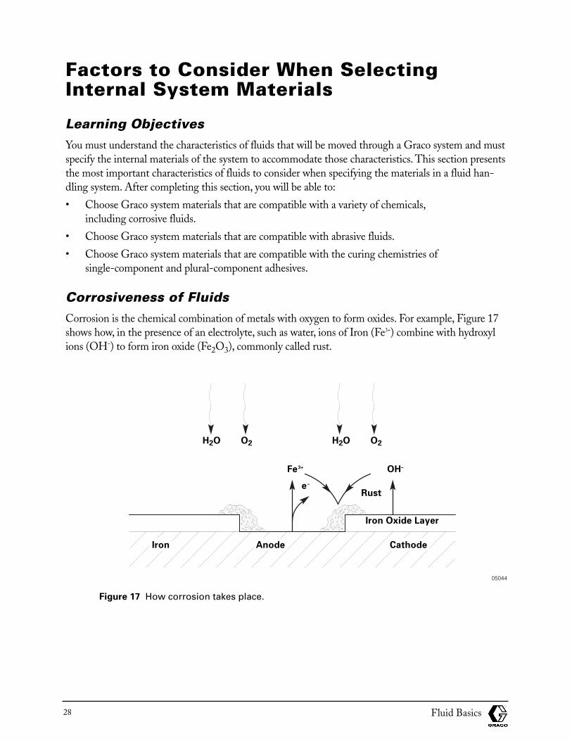
Corrosiveness of FluidsCorrosion is the chemical combination of metals with oxygen to form oxides. For example, Figure 17shows how, in the presence of an electrolyte, such as water, ions of Iron (Fe3+) combine with hydroxylions (OH–) to form iron oxide (Fe2O3), commonly called rust.
Figure 17 How corrosion takes place.
Fluid Basics28
H2O
Rust
Iron Oxide Layer
Iron Anode Cathode
O2 H2O
OH–Fe3+
e–
O2
05044
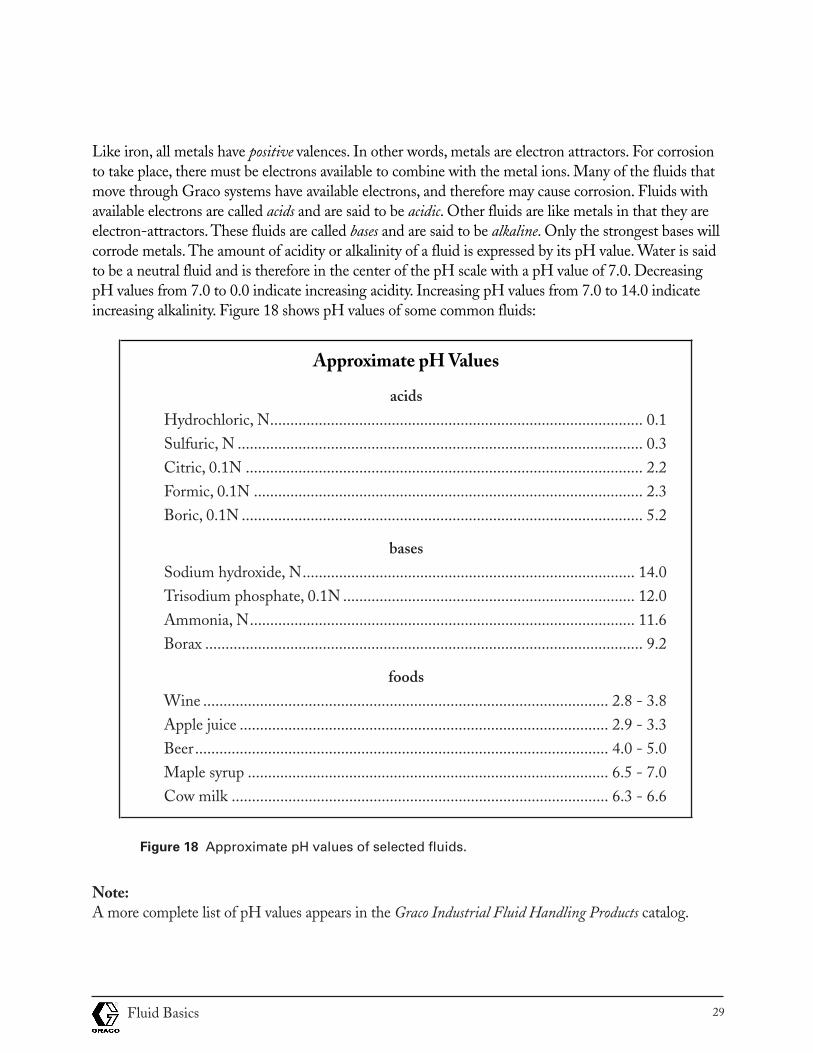
Like iron, all metals have positive valences. In other words, metals are electron attractors. For corrosionto take place, there must be electrons available to combine with the metal ions. Many of the fluids thatmove through Graco systems have available electrons, and therefore may cause corrosion. Fluids withavailable electrons are called acids and are said to be acidic. Other fluids are like metals in that they areelectron-attractors. These fluids are called bases and are said to be alkaline. Only the strongest bases willcorrode metals. The amount of acidity or alkalinity of a fluid is expressed by its pH value. Water is saidto be a neutral fluid and is therefore in the center of the pH scale with a pH value of 7.0. DecreasingpH values from 7.0 to 0.0 indicate increasing acidity. Increasing pH values from 7.0 to 14.0 indicateincreasing alkalinity. Figure 18 shows pH values of some common fluids:
Approximate pH Values
acidsHydrochloric, N............................................................................................ 0.1Sulfuric, N .................................................................................................... 0.3Citric, 0.1N .................................................................................................. 2.2Formic, 0.1N ................................................................................................ 2.3Boric, 0.1N ................................................................................................... 5.2
basesSodium hydroxide, N.................................................................................. 14.0Trisodium phosphate, 0.1N ........................................................................ 12.0Ammonia, N............................................................................................... 11.6Borax ............................................................................................................ 9.2
foodsWine .................................................................................................... 2.8 - 3.8Apple juice ........................................................................................... 2.9 - 3.3Beer...................................................................................................... 4.0 - 5.0Maple syrup ......................................................................................... 6.5 - 7.0Cow milk ............................................................................................. 6.3 - 6.6
Figure 18 Approximate pH values of selected fluids.
Note:A more complete list of pH values appears in the Graco Industrial Fluid Handling Products catalog.
Fluid Basics 29
Acidic fluids will corrode the internal metallic components of a fluid handling system. If a system’smetal parts corrode, several problems are likely to occur:
• The resulting corrosion products (oxides) may become involved in secondary chemical reactions with the fluid being moved, thus contaminating it.
• The corrosion products may flake off and clog the system or contaminate the fluid being moved—or both.
• The corrosion action may deform a pump to the extent that it will not perform properly.
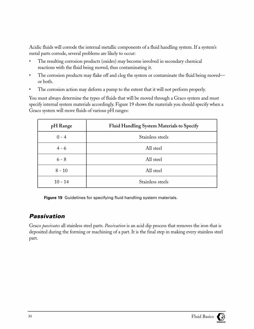
You must always determine the types of fluids that will be moved through a Graco system and mustspecify internal system materials accordingly. Figure 19 shows the materials you should specify when aGraco system will move fluids of various pH ranges:
pH Range Fluid Handling System Materials to Specify
0 - 4 Stainless steels
4 - 6 All steel
6 - 8 All steel
8 - 10 All steel
10 - 14 Stainless steels
Figure 19 Guidelines for specifying fluid handling system materials.
PassivationGraco passivates all stainless steel parts. Passivation is an acid dip process that removes the iron that isdeposited during the forming or machining of a part. It is the final step in making every stainless steelpart.
Fluid Basics30
Chemical Compatibility of Fluids and Pump MaterialsAs stated earlier in this training module, you must specify Graco systems with internal parts that willnot be corroded by the fluids to be moved in those systems. But corrosion is just one kind of damag-ing chemical reaction you must avoid in specifying the internal parts of Graco systems. In fact, thereare many potential problems which may occur if a given material inside a Graco system comes incontact an incompatible fluid.
So how do you know which materials to specify for every possible fluid you might encounter? Whilethis sounds like a daunting problem, reliable help is available. As you might imagine, most of thechemical compatibility problems you are likely to encounter have been encountered and solved beforeby others. The experience gained from Graco’s many decades of dealing with chemical compatibilityproblems has been consolidated in one very useful reference source: the Graco Chemical CompatibilityCharts in the Graco Industrial Products catalog.. You should always have this publication availablewhen you are working with customers. It contains easy-to-use reference charts with the followinginformation:
• Maximum operating temperatures of leather, elastomeric (“rubber”), and plastic materials commonly used as seals and packings in Graco systems.
• Cross-reference between scientific names and trade names of rubber and plastic materials.
• Rating (ranging between “excellent” and “not recommended”) that show the chemical compatibility between hundreds of fluids and twenty-one materials commonly used as seals and packings in Graco systems.
• Ratings that show the chemical compatibility between hundreds of fluids and nine metals andalloys commonly used in Graco systems.
Abrasiveness of FluidsThe abrasiveness of a fluid—that is, its ability to scratch—is another factor you must consider whenspecifying the internal materials in a Graco system. As environmental concerns have increased,solvents previously used in paints and other fluids have been replaced by finely ground materialscalled fillers. Most common fillers are abrasive enough that they eventually will compromise the seal-ing capabilities of the packings and seals in Graco systems. In fact, some fillers are abrasive enough toeventually destroy the metals commonly used in Graco systems. To decide whether abrasiveness isimportant in choosing system materials, you must first identify the fillers that will be present in thefluids to be moved. Then consider two factors, hardness and percent of filler by volume:
Fluid Basics 31
Hardness
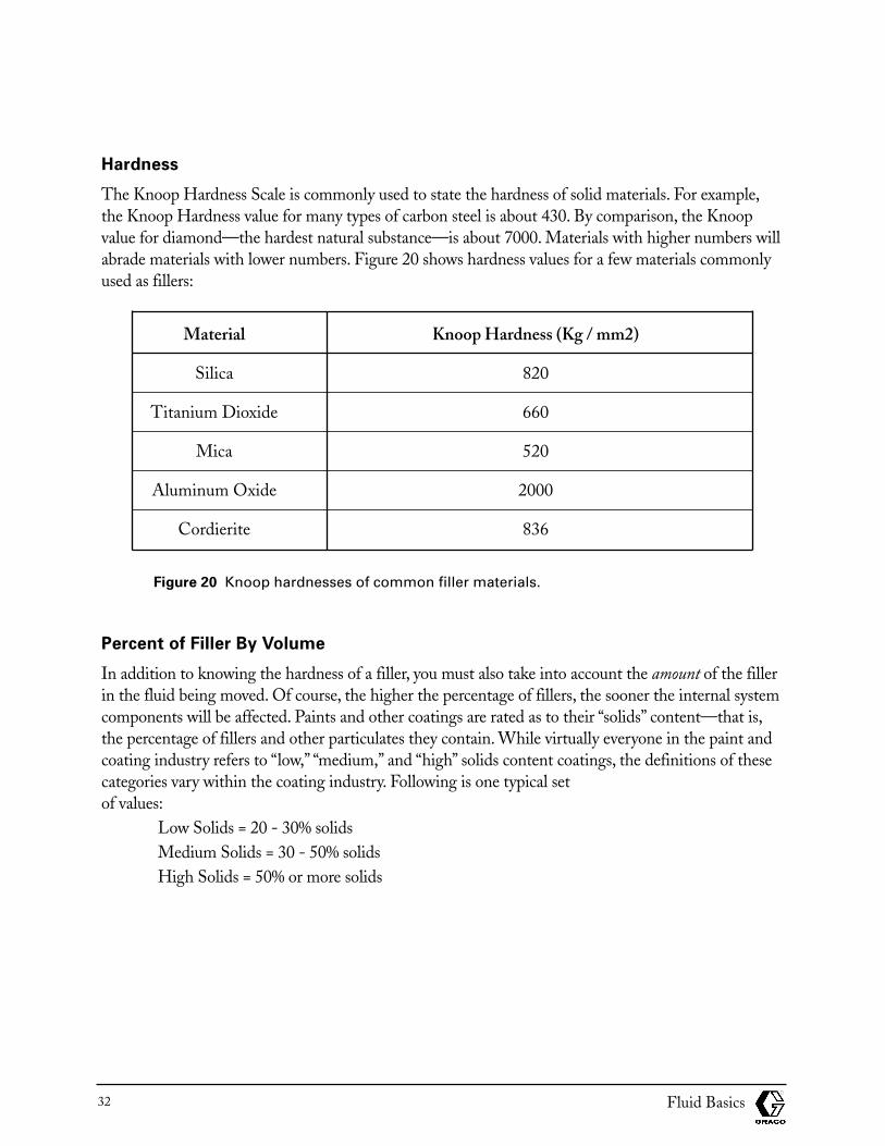
The Knoop Hardness Scale is commonly used to state the hardness of solid materials. For example,the Knoop Hardness value for many types of carbon steel is about 430. By comparison, the Knoopvalue for diamond—the hardest natural substance—is about 7000. Materials with higher numbers willabrade materials with lower numbers. Figure 20 shows hardness values for a few materials commonlyused as fillers:
Material Knoop Hardness (Kg / mm2)
Silica 820
Titanium Dioxide 660
Mica 520
Aluminum Oxide 2000
Cordierite 836
Figure 20 Knoop hardnesses of common filler materials.
Percent of Filler By Volume
In addition to knowing the hardness of a filler, you must also take into account the amount of the fillerin the fluid being moved. Of course, the higher the percentage of fillers, the sooner the internal systemcomponents will be affected. Paints and other coatings are rated as to their “solids” content—that is,the percentage of fillers and other particulates they contain. While virtually everyone in the paint andcoating industry refers to “low,” “medium,” and “high” solids content coatings, the definitions of thesecategories vary within the coating industry. Following is one typical set of values:
Low Solids = 20 - 30% solidsMedium Solids = 30 - 50% solidsHigh Solids = 50% or more solids
Fluid Basics32
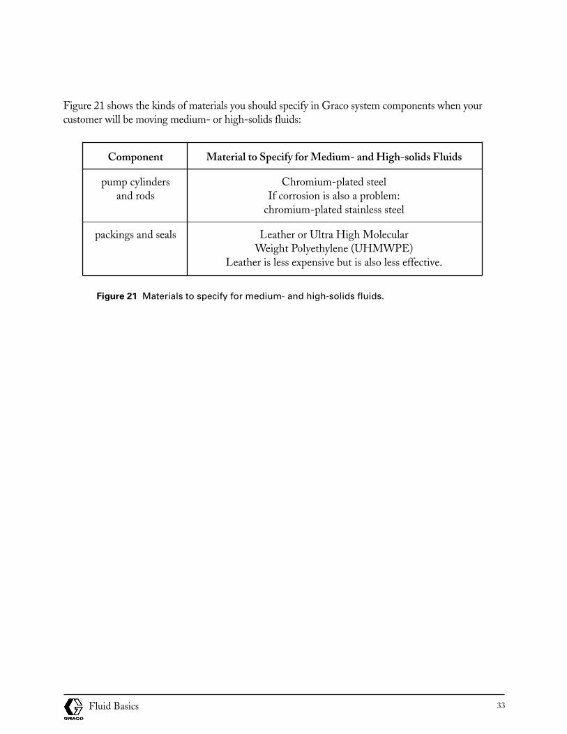
Figure 21 shows the kinds of materials you should specify in Graco system components when yourcustomer will be moving medium- or high-solids fluids:
Component Material to Specify for Medium- and High-solids Fluids
pump cylinders Chromium-plated steeland rods If corrosion is also a problem:
chromium-plated stainless steel
packings and seals Leather or Ultra High Molecular Weight Polyethylene (UHMWPE)
Leather is less expensive but is also less effective.
Figure 21 Materials to specify for medium- and high-solids fluids.
Fluid Basics 33
Progress Check
Directions: After answering the following questions, compare your answers with those provided in theanswer key following this progress check. If you respond to any items incorrectly, return to the text andreview the appropriate topics.
1. Select all characteristics of acidic fluids:
a. pH values above 7.0
b. Alkaline
c. Electron donors
d. Electron attractors
2. Select the statements that are correct:
a. The pH of water is 14.0, at the top of the pH scale.
b. The pH of water is 7.0, in the middle of the pH scale.
c. The pH of water is 0, at the bottom of the pH scale.
d. Fluids with pH’s above 7.0 are acidic.
e. Fluids with pH’s below 7.0 are acidic.
3. Select the problems that may occur as a result of corrosion of metal parts in a Graco system:
a. Corrosion products (oxides) may become involved in secondary chemical reactions with thefluid being moved, thus contaminating it.
b. Corrosion products may flake off and clog the system or contaminate the fluid beingmoved—or both.
c. Corrosive action may passivate the metals in the system, causing them to become highlyacidic.
d. Corrosion action may deform a pump to the extent that it does not perform properly.
e. Corrosion may change the pH of the fluid being moved.
4. Passivation removes corrosion from stainless steel.
a. True
b. False
5. Your customer wants to pump toluene at room temperature in a Graco system that containsPTFE seals. In what reference document would you find information on whether the seals willstand up to the toluene?
Fluid Basics34
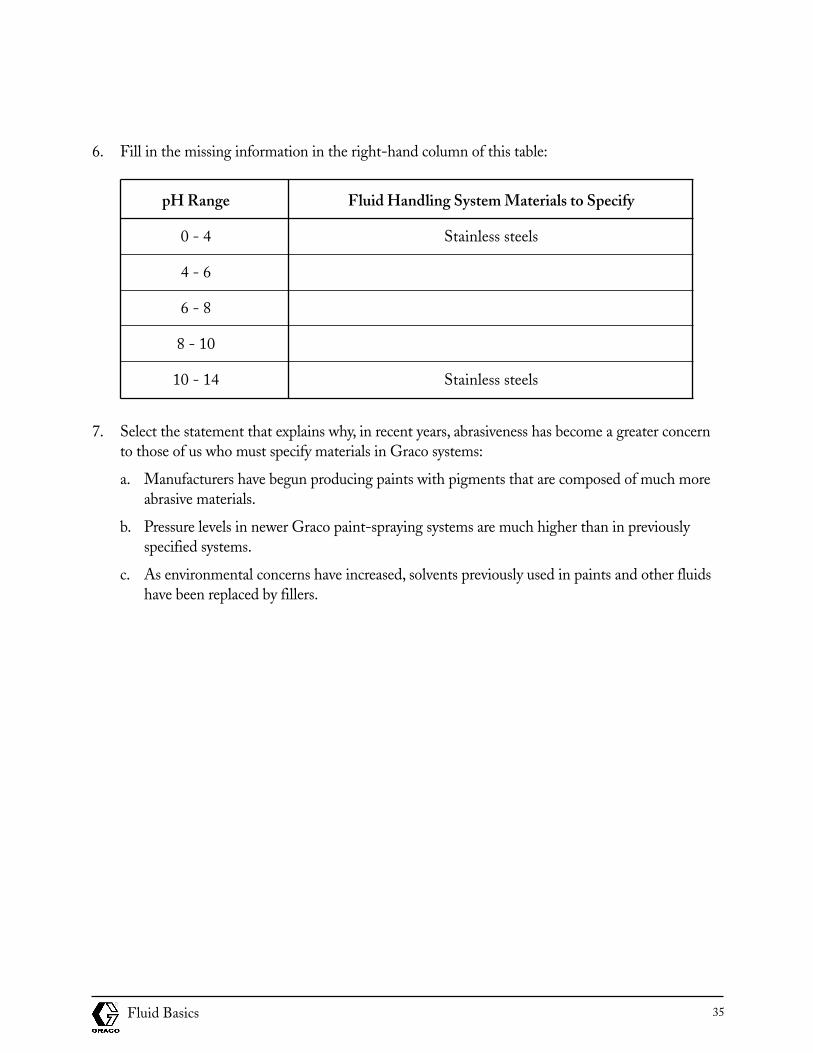
6. Fill in the missing information in the right-hand column of this table:
pH Range Fluid Handling System Materials to Specify
0 - 4 Stainless steels
4 - 6
6 - 8
8 - 10
10 - 14 Stainless steels
7. Select the statement that explains why, in recent years, abrasiveness has become a greater concernto those of us who must specify materials in Graco systems:
a. Manufacturers have begun producing paints with pigments that are composed of much moreabrasive materials.
b. Pressure levels in newer Graco paint-spraying systems are much higher than in previouslyspecified systems.
c. As environmental concerns have increased, solvents previously used in paints and other fluidshave been replaced by fillers.
Fluid Basics 35
Answers to progress check
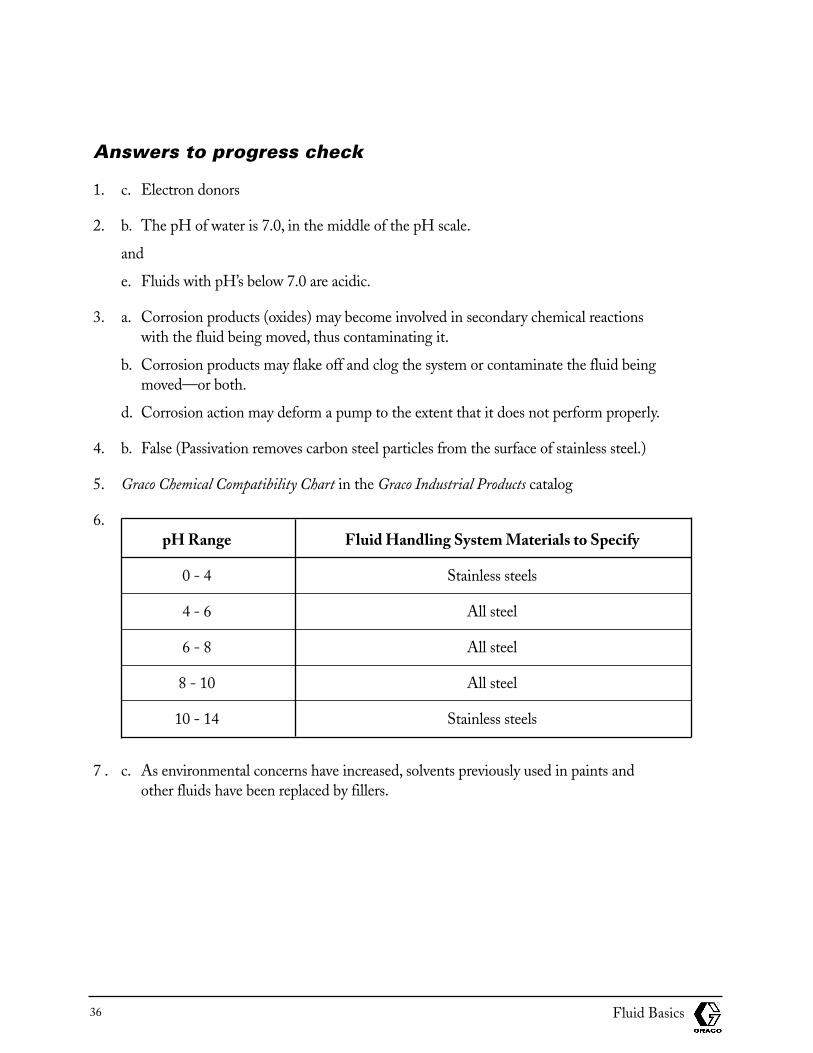
1. c. Electron donors
2. b. The pH of water is 7.0, in the middle of the pH scale.
and
e. Fluids with pH’s below 7.0 are acidic.
3. a. Corrosion products (oxides) may become involved in secondary chemical reactions with the fluid being moved, thus contaminating it.
b. Corrosion products may flake off and clog the system or contaminate the fluid being moved—or both.
d. Corrosion action may deform a pump to the extent that it does not perform properly.
4. b. False (Passivation removes carbon steel particles from the surface of stainless steel.)
5. Graco Chemical Compatibility Chart in the Graco Industrial Products catalog
6.pH Range Fluid Handling System Materials to Specify
0 - 4 Stainless steels
4 - 6 All steel
6 - 8 All steel
8 - 10 All steel
10 - 14 Stainless steels
7 . c. As environmental concerns have increased, solvents previously used in paints and other fluids have been replaced by fillers.
Fluid Basics36
Fluid Basics 37
Module Evaluation
The purpose of this Module Evaluation is to help the Graco Technical Communications department determine the usefulness and effectiveness of the module.
Instructions: Please complete the evaluation, tear it on the perforation, and return it Graco TechnicalCommunications Department, P.O. Box 1441, Minneapolis, MN 55440-1441, USA.
1. Based on the objectives, this module:
Significantly exceeded my expectations
Exceeded my expectations
Met my expectations
Was below my expectations
Was significantly below my expectations
2. Why did you select the above rating?
3. How do you plan to use the module information in your job?
4. How do you think the module could be improved?
I verify that I have successfully completed Module No. _______ Title_________________________
Signature _________________________________________________
Date _______________________
Fluid Basics38
GracoTechnical Communications Dept.P.O. Box 1441Minneapolis, MN 55440-1441 U.S.A.
(fold here)
(fold here)
Fluid Basics 39
This module was developed by the Graco Technical Communications Department with assistancefrom the following individuals:
Tony BrajdichGlen MuirKeith Weiss
The Graco Concept and Theory Training program consists of the following topics:
Fluid Basics
Atomization
Electrostatic Spray Finishing
Safety
Airspray Technology
Fluid Types: Paints and Other Coatings
Fluid Types: Lubricants
Fluid Types: Sealants and Adhesives
Airless Atomization
Spraying Techniques
Transfer Efficiency
Fluid Movement
Fluid Controls
Pumps
Motors and Power Sources
Plural Component Paint Handling
Plural Component Sealant and Adhesive Handling
Paint Circulating Systems
Automatic Finishing
Lube Reels and Dispense Valves
Lube Metering Systems
Electronic Fluid Management Systems
Graco, Inc.P.O. Box 1441 - Minneapolis, MN 55440-1441
©1995 Graco Inc. Form No. 321-026 7/95 Printed in U.S.A.