Embed Size (px)
Citation preview

Installation GuideFLOWTITE GRP Pipe Systemsw w w . f l o w t i t e p i p e . c o m
f o r B u r i e d P i p e
18585 Samuels Rd. Zachary, La. 70791 PH. 225-658-6166 Fax 225-658-0947
U.S. COMPOSITE PIPE SOUTH, LLC.
MEMBER OF KTI PIPE GROUP OF COMPANIES
2
01
02
03
04
05
06
1 Introductory Information 4 1.1 Foreword ................................................................................................................... 4 1.2 Soil-Pipe System ...................................................................................................... 4 1.3 Field Technician ........................................................................................................ 5 1.4 Safety ........................................................................................................................ 5
2 Shipping, Handling and Storage 6 2.1 Inspecting Pipe ......................................................................................................... 6 2.2 Repairing Pipe .......................................................................................................... 6 2.3 Unloading and Handling Pipe ................................................................................... 6 2.4 Site Pipe Storage ...................................................................................................... 7 2.5 Storing Gaskets and Lubricant ................................................................................. 7 2.6 Transporting Pipe ..................................................................................................... 8 2.7 Handling Nested Pipes ............................................................................................. 8
3 Pipe Installation Procedure 9 3.1 Standard Trench ....................................................................................................... 9 3.2 Pipe Bedding ............................................................................................................ 9 3.3 Backfill Materials ..................................................................................................... 10 3.4 Installation Types .................................................................................................... 10 3.5 Backfilling Pipe ....................................................................................................... 11 3.6 Compaction Above Pipe ......................................................................................... 12 3.7 Pipe Deflections ...................................................................................................... 12
4 Joining Pipes 13 4.1 FLOWTITE Double Bell Couplings ......................................................................... 13 4.2 Locked Joints ......................................................................................................... 15 4.3 Flanged Joints ........................................................................................................ 15 4.4 Layup Joint ............................................................................................................. 16 4.5 Other Joining Methods ........................................................................................... 17
5 Thrust Restraints, Concrete Encasement and Connections to Rigid Structures 18 5.1 Concrete Encasement ............................................................................................ 19 5.2 Connections to Rigid Structures ............................................................................. 20 5.3 Casings (Tunnels) ................................................................................................... 22 5.4 Concrete-Wall Connections .................................................................................... 22
6 Field Adjustments 24 6.1 Length Adjustment .................................................................................................. 24 6.2 Field Closures with FLOWTITE Couplings ............................................................. 24 6.3 Field Closures with Non-FLOWTITE Couplings ..................................................... 25
3
7 Other Installation Procedures and Considerations 26 7.1 Multiple Pipes in Same Trench............................................................................... 26 7.2 Cross-Overs............................................................................................................ 26 7.3 Unstable Trench Bottom ......................................................................................... 26 7.4 Flooded Trench ...................................................................................................... 27 7.5 Use of Trench Supports ......................................................................................... 27 7.6 Trench Construction in Rock .................................................................................. 27 7.7 Inadvertent Over-Excavation .................................................................................. 28 7.8 Installation of Pipes on Slopes (Parallel) ................................................................ 28
8 Accommodating Valves and Chambers 29 8.1 Anchoring In-Line Valves........................................................................................ 29 8.2 Air and Vacuum Valves .......................................................................................... 32 8.3 Clean Out and Scour Valves .................................................................................. 33
9 Post-Installation 34 9.1 Checking the Installed Pipe .................................................................................... 34 9.2 Correcting Over-Deflected Pipe.............................................................................. 34 9.3 Field Hydrotesting. .................................................................................................. 35 9.4 Field Joint Tester .................................................................................................... 36 9.5 Field Air Test .......................................................................................................... 36
10 Alternate Installations 37 10.1 Wide Trench ......................................................................................................... 37 10.2 Cement Stabilized Backfill .................................................................................... 37
Appendix 39 Appendix AWWA M 45
07
08
09
10
App.
3
4
1 Introductory Information
1.1 Foreword
This document is part of the FLOWTITE® documentation for the users of FLOWTITE products. It is to be used in connection with the FLOWTITE Product Guide and is intended to assist the installer in understanding the requirements and procedures for the successful handling and buried installation of FLOWTITE pipe. The appendices may serve as a helpful source of data for Owner’s engineers.
This document mainly addresses the usual circumstances that may be encountered in the field; unique situations requiring special considerations are not addressed and should be resolved in cooperation with the supplier.
Installations other than direct bury, such as trenchless, sub-aqueous or above-ground, are not discussed in this manual. Consult the supplier for suggested procedures and limitations in these cases.
This installation guide is not meant to replace common sense, good engineering practices and judgement, applicable laws, safety, environ mental and other regulations, local ordinances, nor the specifications and instructions of the owner and/or the owner’s engineer, who is/are the final authority on each job. Should any conflicting information in this brochure create doubts as to how to proceed, please consult the supplier and the owner’s engineer to obtain assistance.
The installation procedures outlined in this Installation Guide and the suggestions of the Field Technicians, when carefully followed, will help with the thorough execution of a proper, long-lasting installation. Consult the supplier on any questions or when variations from this installation guide are being considered.
! Note: These installation instructions are based on the structural design procedures of AWWA M 45.
1.2 Soil-pipe system
The strength and flexibility of FLOWTITE pipes offers a unique potential for soil-structure interaction that allows optimum system performance. The pipe design with glass fiber reinforcement placement allows for flexibility and strength. The trench geometry, along with selection, placement and compaction of backfill ensures the integrity of the system.
Generally, there are two sets of loads that the pipe is subject to:
1 external loads resulting from overburden, surface loads and traffic, create bending stresses in the pipe wall;
2 internal pressures create hoop stresses in the pipe and unbalanced thrust creating axial stresses.
Conversion from Customary Inch–Lb Units to Metric (SI)
This version of the Installation Guide for FLOWTITE Pipe is presented using customary inch–lb units. In the text, rounded metric units are shown in parentheses for the convenience of the reader. However, many tables are presented in inch-lb units only. To show both unit systems would lead to very lengthy and complex tables. For the user who may wish to convert the inch-lb units to metric (SI), the following conversion tables will be helpful.
Throughout the Guide, the designations PN, DN and SN are used. These stand for Nominal Pressure, Nominal Diameter and Nominal Stiffness, respectively.
The following table gives the conversion factors that can be used as necessary to convert inch-lb units to metric (SI).
Inch – lb units Multiply by Metric (SI) units to convertInch (in) 25.4 Millimetre (mm)Pound (lb) 2.2 Kilogram (kg)Foot (ft) 0.305 MetrePressure (psi) 6894 N/m2
Pressure (psi) 0.0690 barFt – lb (torque) 1.356 N - metrePound force 4.45 NPound per ft3 (pcf) 0.157 kN/M3
PIPE STIFFNESS (psi) PIPE STIFFNESS (N/m2)(Initial Stiffness) (Initial Stiffness)
18 2500 36 5000 46 6400 72 10000
A special note is necessary for pipe stiffness (SN). The testing and reporting of pipe stiffness is on a somewhat different basis in the ASTM and AWWA standards and the ISO and CEN standards. Briefly, the ASTM and AWWA standards measure and report stiffness at 5% deflection and on the basis of EI/r3. The ISO and CEN standards measure stiffness at 3% deflection and report as referenced to zero deflection on the basis of EI/D3. This can lead to some problems in direct conversion of stiffness from one system to the other. The following listing gives the correct conversion.
01
1.3 Field Technician
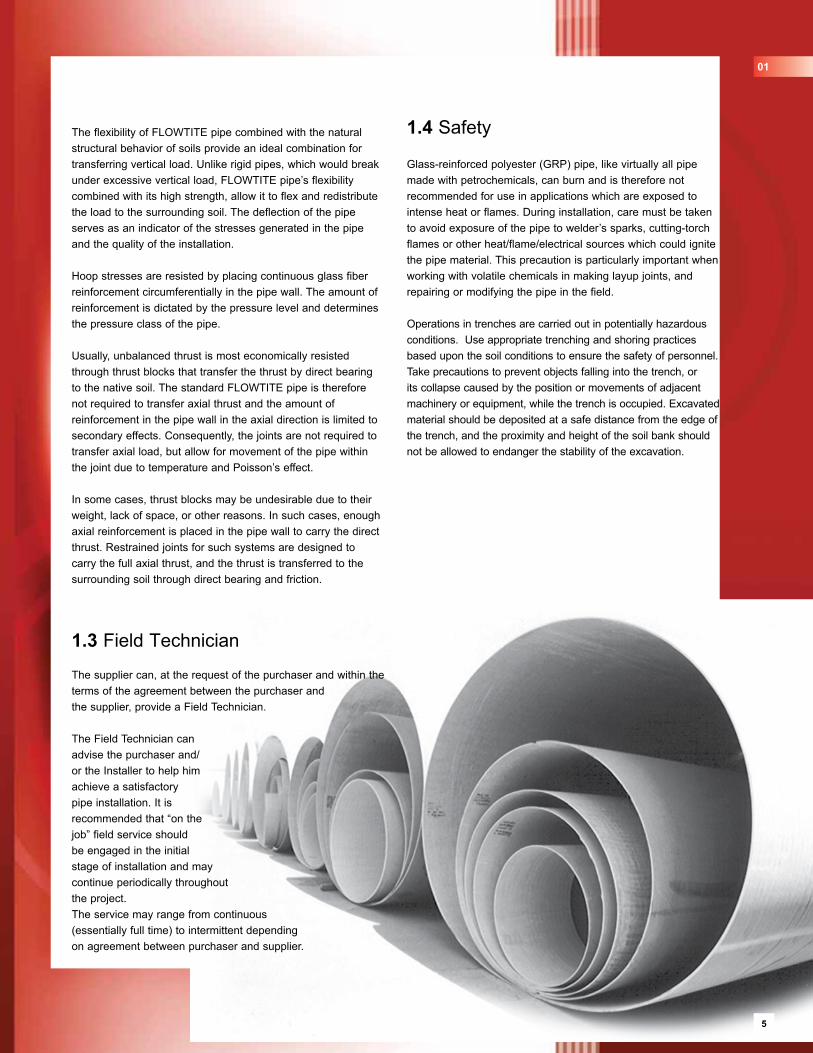
The supplier can, at the request of the purchaser and within the terms of the agreement between the purchaser and the supplier, provide a Field Technician.
The Field Technician can advise the purchaser and/or the Installer to help him achieve a satisfactory pipe installation. It is recommended that “on the job” field service should be engaged in the initial stage of installation and may continue periodically throughout the project. The service may range from continuous (essentially full time) to intermittent depending on agreement between purchaser and supplier.
1.4 Safety
Glass-reinforced polyester (GRP) pipe, like virtually all pipe made with petrochemicals, can burn and is therefore not recommended for use in applications which are exposed to intense heat or flames. During installation, care must be taken to avoid exposure of the pipe to welder’s sparks, cutting-torch flames or other heat/flame/electrical sources which could ignite the pipe material. This precaution is particularly important when working with volatile chemicals in making layup joints, and repairing or modifying the pipe in the field.
Operations in trenches are carried out in potentially hazardous conditions. Use appropriate trenching and shoring practices based upon the soil conditions to ensure the safety of personnel. Take precautions to prevent objects falling into the trench, or its collapse caused by the position or movements of adjacent machinery or equipment, while the trench is occupied. Excavated material should be deposited at a safe distance from the edge of the trench, and the proximity and height of the soil bank should not be allowed to endanger the stability of the excavation.
The flexibility of FLOWTITE pipe combined with the natural structural behavior of soils provide an ideal combination for transferring vertical load. Unlike rigid pipes, which would break under excessive vertical load, FLOWTITE pipe’s flexibility combined with its high strength, allow it to flex and redistribute the load to the surrounding soil. The deflection of the pipe serves as an indicator of the stresses generated in the pipe and the quality of the installation.
Hoop stresses are resisted by placing continuous glass fiber reinforcement circumferentially in the pipe wall. The amount of reinforcement is dictated by the pressure level and determines the pressure class of the pipe.
Usually, unbalanced thrust is most economically resisted through thrust blocks that transfer the thrust by direct bearing to the native soil. The standard FLOWTITE pipe is therefore not required to transfer axial thrust and the amount of reinforcement in the pipe wall in the axial direction is limited to secondary effects. Consequently, the joints are not required to transfer axial load, but allow for movement of the pipe within the joint due to temperature and Poisson’s effect.
In some cases, thrust blocks may be undesirable due to their weight, lack of space, or other reasons. In such cases, enough axial reinforcement is placed in the pipe wall to carry the direct thrust. Restrained joints for such systems are designed to carry the full axial thrust, and the thrust is transferred to the surrounding soil through direct bearing and friction.
01
5
6
2 Shipping, Handling and Storage
2.1 Inspecting Pipe
All pipes should be inspected upon receipt at the job site to insure that no damage has occurred in transit.
Depending on length of storage, amount of job site handling and other factors that may influence the pipe's condition, it is recommended that the pipe be re-inspected just prior to installation. Inspect the shipment upon delivery, as follows:
1 Make an overall inspection of the load. If the load is intact, ordinary inspection while unloading will normally be sufficient to make sure the pipe has arrived without damage.
2 If the load has shifted or indicates rough treatment, carefully inspect each pipe section for damage. Generally, an exterior inspection will be sufficient to detect any damage. When pipe size permits, an interior inspection of the pipe surface at the location of an exterior scrape may be helpful to determine if the pipe is damaged.
3 Check the quantity of each item against the bill of lading.
4 Note on the bill of lading any transit damage or loss and have the carrier representative sign your copy of the receipt. Claims against the carrier should be in accordance with their instructions.
5 If any imperfections or damage is found, segregate the affected pipes and contact the supplier. Do not use pipe that appears damaged or defective.
2.2
2.3 Unloading and Handling Pipe
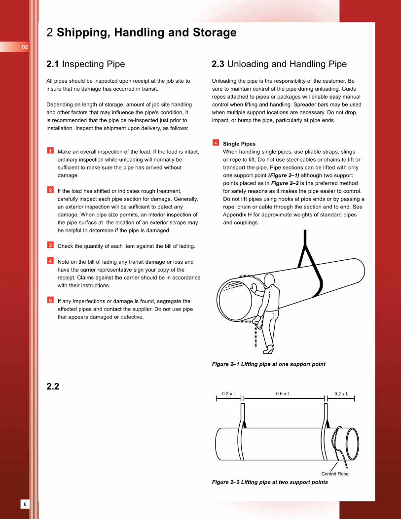
Unloading the pipe is the responsibility of the customer. Be sure to maintain control of the pipe during unloading. Guide ropes attached to pipes or packages will enable easy manual control when lifting and handling. Spreader bars may be used when multiple support locations are necessary. Do not drop, impact, or bump the pipe, particularly at pipe ends.
• Single Pipes When handling single pipes, use pliable straps, slings
or rope to lift. Do not use steel cables or chains to lift or transport the pipe. Pipe sections can be lifted with only one support point (Figure 2–1) although two support points placed as in Figure 2–2 is the preferred method for safety reasons as it makes the pipe easier to control. Do not lift pipes using hooks at pipe ends or by passing a rope, chain or cable through the section end to end. See Appendix H for approximate weights of standard pipes and couplings.
Figure 2–1 Lifting pipe at one support point
0.2 x L 0.6 x L 0.2 x L
Control Rope
02
Figure 2–2 Lifting pipe at two support points
7
2.5 Storing Gaskets and Lubricant
Rubber ring gaskets, when shipped separately from the couplings, should be stored in the shade in their original packing and should not be exposed to sunlight except during the pipe joining. Also, the gaskets must be protected from exposure to greases and oils which are petroleum derivatives, and from solvents and other harmful substances.
Gasket lubricant should be carefully stored to prevent damage. Partially used buckets should be resealed to prevent contamination of the lubricant. If temperatures during installation are below 40° F (5° C), gaskets and lubricant should be sheltered until used.
2.4 Site Pipe Storage
It is generally advantageous to store pipe on flat timber supports to facilitate placement and removal of lifting slings around the pipe.
When storing pipe directly on the ground, be sure that the area is relatively flat and free of rocks and other potentially damaging debris. Placing the pipe on mounds of backfill material has been found to be an effective way of site storing the pipe. All pipes should be chocked to prevent rolling in high winds.
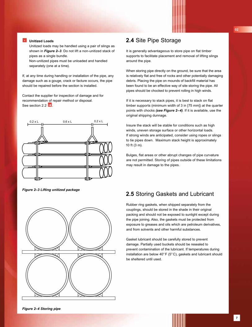
If it is necessary to stack pipes, it is best to stack on flat timber supports (minimum width of 3 in [75 mm]) at the quarter points with chocks (see Figure 2–4). If it is available, use the original shipping dunnage.
Insure the stack will be stable for conditions such as high winds, uneven storage surface or other horizontal loads.If strong winds are anticipated, consider using ropes or slings to tie pipes down. Maximum stack height is approximately 10 ft (3 m).
Bulges, flat areas or other abrupt changes of pipe curvature are not permitted. Storing of pipes outside of these limitations may result in damage to the pipes.
Figure 2–4 Storing pipe
• Unitized Loads Unitized loads may be handled using a pair of slings as
shown in Figure 2–3. Do not lift a non-unitized stack of pipes as a single bundle.
Non-unitized pipes must be unloaded and handled separately (one at a time).
If, at any time during handling or installation of the pipe, any damage such as a gouge, crack or facture occurs, the pipe should be repaired before the section is installed.
Contact the supplier for inspection of damage and for recommendation of repair method or disposal. See section 2.2 ➜ .
Figure 2–3 Lifting unitized package
0.2 x L 0.6 x L 0.2 x L
02
7
8
2.7 Handling Nested Pipes
Pipes may be nested (smaller diameter pipes inside of larger sizes). These pipes generally have special packaging and may require special procedures for unloading, handling, storing and transporting. The following general procedures should always be followed:
1 Always lift the nested bundle using at least two pliable straps (Figure 2–6). Limitations, if any, for spacing between straps and lifting locations will be specified for each project. Insure that the lifting slings have sufficient capacity for the bundle weight. This may be calculated from the approximate pipe weights given in Appendix H.
2 Nested pipes are usually best stored in the transport packaging. Stacking of these packages is not advised unless otherwise specified.
3 Nested pipe bundles can only be safely transported in the original transport packaging. Special requirements, if any, for support, configuration and/or strapping to the vehicle will be specified for each project.
4 Package removal and de-nesting of the inside pipe(s) is best accomplished at a de-nesting station. Inside pipes, starting with the smallest size may be removed by lifting slightly with an inserted padded boom to suspend the section and carefully move it out of the bundle without damaging the other pipes (Figure 2–7).
When weight, length and/or equipment limitations preclude the use of this method, procedures for sliding the inside pipe(s) out of the bundle will be recommended for each project.
Figure 2–6 Double support point for nested pipes Figure 2–7 De-nesting with padded boom on forklift truck
2.6 Transporting Pipe
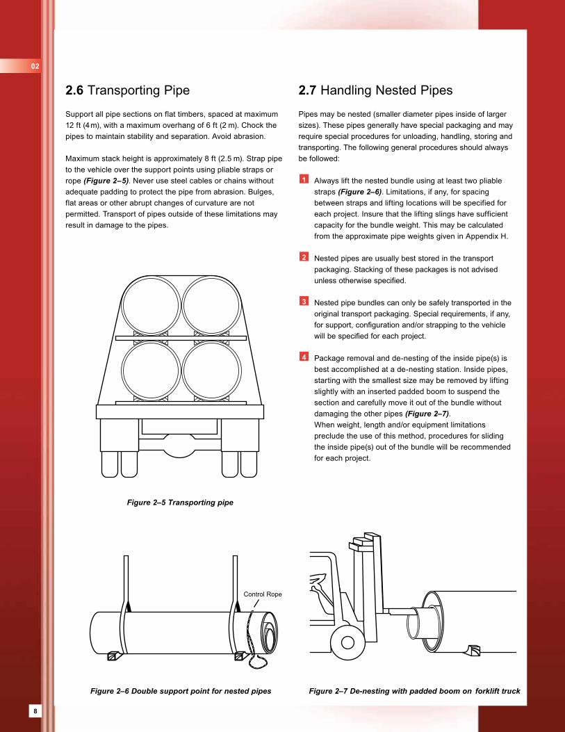
Support all pipe sections on flat timbers, spaced at maximum 12 ft (4 m), with a maximum overhang of 6 ft (2 m). Chock the pipes to maintain stability and separation. Avoid abrasion.
Maximum stack height is approximately 8 ft (2.5 m). Strap pipe to the vehicle over the support points using pliable straps or rope (Figure 2–5). Never use steel cables or chains without adequate padding to protect the pipe from abrasion. Bulges, flat areas or other abrupt changes of curvature are not permitted. Transport of pipes outside of these limitations may result in damage to the pipes.
Figure 2–5 Transporting pipe
Control Rope
02
9
3.2 Pipe Bedding
The bedding should be placed over a firm, stable trench bottom so as to provide proper support. The finished bed must provide a firm, stable and uniform support for the pipe barrel and any protruding feature of its joint.
Provide 4 - 6 in (100 - 150 mm) (minimum) of bedding below the barrel and 3 in (75 mm) (minimum) below the coupling. For soft or unstable trench bottom, an additional foundation may be needed to achieve firm support for the bedding, see section 7.3 ➜ .
The bedding material may need to be imported to provide proper gradation and pipe support. The recommended materials for bedding are SC1 or SC2. To determine if the native material is acceptable as a bedding material, it should meet all of the requirements of the pipe zone backfill. This determination must be made constantly during the pipe installation process because native soil conditions may vary and change suddenly along the length of a pipeline.
The bed must be over-excavated at each joint location to ensure that the pipe will have a continuous support and does not rest on the couplings. The coupling area must be properly bedded and backfilled after the joint assembly is completed. See Figure 3–2 and Figure 3–3 for proper and improper bedding support.
The type of installation procedure appropriate for FLOWTITE pipe varies with pipe stiffness, cover depth, trench width, native soil characteristics, surcharge loads and backfill materials.
The native material must adequately confine the pipe zone backfill to achieve proper pipe support. The following installation procedures are intended to assist the installer in achieving a proper pipe installation
3.1 Standard Trench
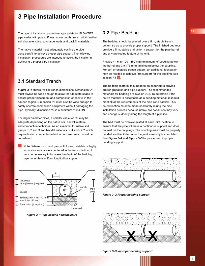
Figure 3–1 shows typical trench dimensions. Dimension “A” must always be wide enough to allow for adequate space to ensure proper placement and compaction of backfill in the haunch region. Dimension “A” must also be wide enough to safely operate compaction equipment without damaging the pipe. Typically, dimension “A” is a minimum of 0.4 DN.
For larger diameter pipes, a smaller value for “A” may be adequate depending on the native soil, backfill material and compaction technique. As an example, for native soil groups 1, 2 and 3 and backfill materials SC1 and SC2 which require limited compaction effort, a narrower trench could be considered.
! Note: Where rock, hard pan, soft, loose, unstable or highly expansive soils are encountered in the trench bottom, it may be necessary to increase the depth of the bedding layer to achieve uniform longitudinal support.
3 Pipe Installation Procedure
Figure 3–2 Proper bedding support
Figure 3–3 Improper bedding support
Figure 3–1 Pipe backfill nomenclature
DN/2 max. 12 in (300 mm) required
Backfill
Bedding: min 4 in (100 mm)max. 6 in (150 mm)
Foundation (if required)
HaunchDN
A
Pipezone
Native soil
03
9
10
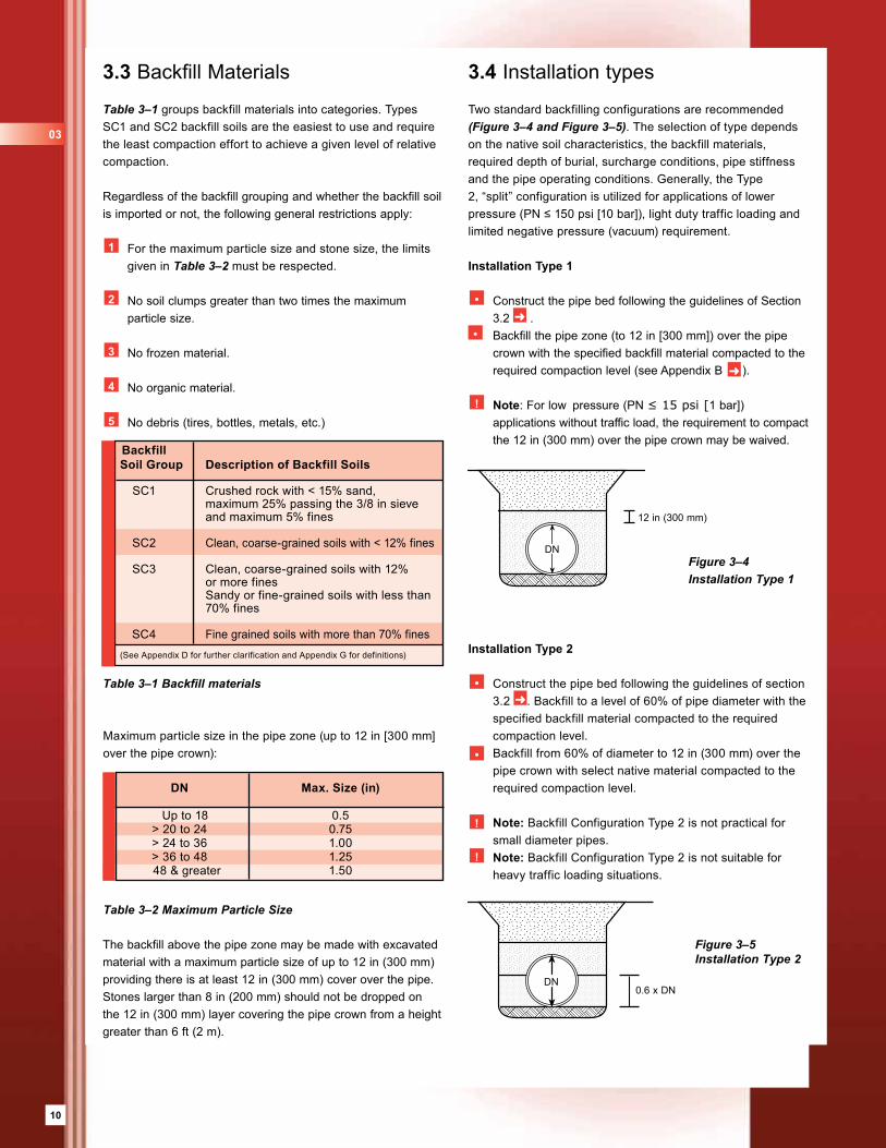
3.4 Installation types
Two standard backfilling configurations are recommended (Figure 3–4 and Figure 3–5). The selection of type depends on the native soil characteristics, the backfill materials, required depth of burial, surcharge conditions, pipe stiffness and the pipe operating conditions. Generally, the Type 2, “split” configuration is utilized for applications of lower pressure (PN ≤ 150 psi [10 bar]), light duty traffic loading and limited negative pressure (vacuum) requirement.
Installation Type 1
• Construct the pipe bed following the guidelines of Section 3.2 ➜ .
• Backfill the pipe zone (to 12 in [300 mm]) over the pipe crown with the specified backfill material compacted to the required compaction level (see Appendix B ➜ ).
! Note: For low pressure (PN ≤ 15 psi [1 bar]) applications without traffic load, the requirement to compact the 12 in (300 mm) over the pipe crown may be waived.
Installation Type 2
• Construct the pipe bed following the guidelines of section 3.2 ➜ . Backfill to a level of 60% of pipe diameter with the specified backfill material compacted to the required compaction level.
• Backfill from 60% of diameter to 12 in (300 mm) over the pipe crown with select native material compacted to the required compaction level.
! Note: Backfill Configuration Type 2 is not practical for small diameter pipes.
! Note: Backfill Configuration Type 2 is not suitable for heavy traffic loading situations.
Maximum particle size in the pipe zone (up to 12 in [300 mm] over the pipe crown):
The backfill above the pipe zone may be made with excavated material with a maximum particle size of up to 12 in (300 mm) providing there is at least 12 in (300 mm) cover over the pipe. Stones larger than 8 in (200 mm) should not be dropped on the 12 in (300 mm) layer covering the pipe crown from a height greater than 6 ft (2 m).
Table 3–2 Maximum Particle Size
3.3 Backfill Materials
Table 3–1 groups backfill materials into categories. Types SC1 and SC2 backfill soils are the easiest to use and require the least compaction effort to achieve a given level of relative compaction.
Regardless of the backfill grouping and whether the backfill soil is imported or not, the following general restrictions apply:
1 For the maximum particle size and stone size, the limits given in Table 3–2 must be respected.
2 No soil clumps greater than two times the maximum particle size.
3 No frozen material.
4 No organic material.
5 No debris (tires, bottles, metals, etc.)
Table 3–1 Backfill materials
Figure 3–4 Installation Type 1
DN
12 in (300 mm)
Figure 3–5 Installation Type 2
DN0.6 x DN
Backfill Soil Group Description of Backfill Soils
SC1 Crushed rock with < 15% sand, maximum 25% passing the 3/8 in sieve and maximum 5% fines
SC2 Clean, coarse-grained soils with < 12% fines
SC3 Clean, coarse-grained soils with 12% or more fines Sandy or fine-grained soils with less than 70% fines
SC4 Fine grained soils with more than 70% fines(See Appendix D for further clarification and Appendix G for definitions)
DN Max. Size (in)
Up to 18 0.5 > 20 to 24 0.75 > 24 to 36 1.00 > 36 to 48 1.25 48 & greater 1.50
03
11
3.5 Backfilling Pipe
Immediate backfilling after joining is recommended as it will prevent two hazards, floating of pipe due to heavy rain and thermal movements due to temperature change. Floating of pipe can damage the pipe and create unnecessary reinstallation costs. Thermal expansion and contraction can cause loss of seal due to movement of several pipe lengths accumulated at one joint.
If sections of pipe are placed into the trench and backfilling is delayed, each pipe should have the center section backfilled to the crown to help minimize movements at the joint.
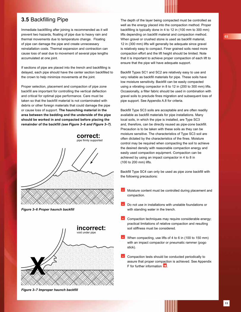
Proper selection, placement and compaction of pipe zone backfill are important for controlling the vertical deflection and critical for optimal pipe performance. Care must be taken so that the backfill material is not contaminated with debris or other foreign materials that could damage the pipe or cause loss of support. The haunching material in the area between the bedding and the underside of the pipe should be worked in and compacted before placing the remainder of the backfill (see Figure 3–6 and Figure 3–7).
The depth of the layer being compacted must be controlled as well as the energy placed into the compaction method. Proper backfilling is typically done in 4 to 12 in (100 mm to 300 mm) lifts depending on backfill material and compaction method. When gravel or crushed stone is used as backfill material, 12 in (300 mm) lifts will generally be adequate since gravel is relatively easy to compact. Finer grained soils need more compaction effort and the lift height should be limited. Note that it is important to achieve proper compaction of each lift to ensure that the pipe will have adequate support.
Backfill Types SC1 and SC2 are relatively easy to use and very reliable as backfill materials for pipe. These soils have low moisture sensitivity. Backfill can be easily compacted using a vibrating compactor in 8 to 12 in (200 to 300 mm) lifts. Occasionally, a filter fabric should be used in combination with gravel soils to preclude fines migration and subsequent loss of pipe support. See Appendix A.8 for criteria.
Backfill Type SC3 soils are acceptable and are often readily available as backfill materials for pipe installations. Many local soils, in which the pipe is installed, are Type SC3 and, therefore, can be directly reused as pipe-zone backfill. Precaution is to be taken with these soils as they can be moisture sensitive. The characteristics of Type SC3 soil are often dictated by the characteristics of the fines. Moisture control may be required when compacting the soil to achieve the desired density with reasonable compaction energy and easily used compaction equipment. Compaction can be achieved by using an impact compactor in 4 to 8 in(100 to 200 mm) lifts.
Backfill Type SC4 can only be used as pipe zone backfill with the following precautions:
• Moisture content must be controlled during placement and compaction.
• Do not use in installations with unstable foundations or with standing water in the trench.
• Compaction techniques may require considerable energy; practical limitations of relative compaction and resulting soil stiffness must be considered.
• When compacting, use lifts of 4 to 6 in (100 to 150 mm) with an impact compactor or pneumatic rammer (pogo stick).
• Compaction tests should be conducted periodically to assure that proper compaction is achieved. See Appendix F for further information ➜ .
Figure 3–6 Proper haunch backfill
correct: pipe firmly supported
03
incorrect: void under pipe
Figure 3–7 Improper haunch backfill
11
12
The compaction of finer grain backfill is most easily accomplished when the material is at or near its optimum moisture content. When backfilling reaches the pipe's spring line, all compaction should start near the trench sides and proceed towards the pipe.
Pipe zone backfill can be placed and compacted in such a way as to cause the pipe to ovalize slightly in the vertical direction. Initial vertical ovalization, however, must not exceed 1.5 % of
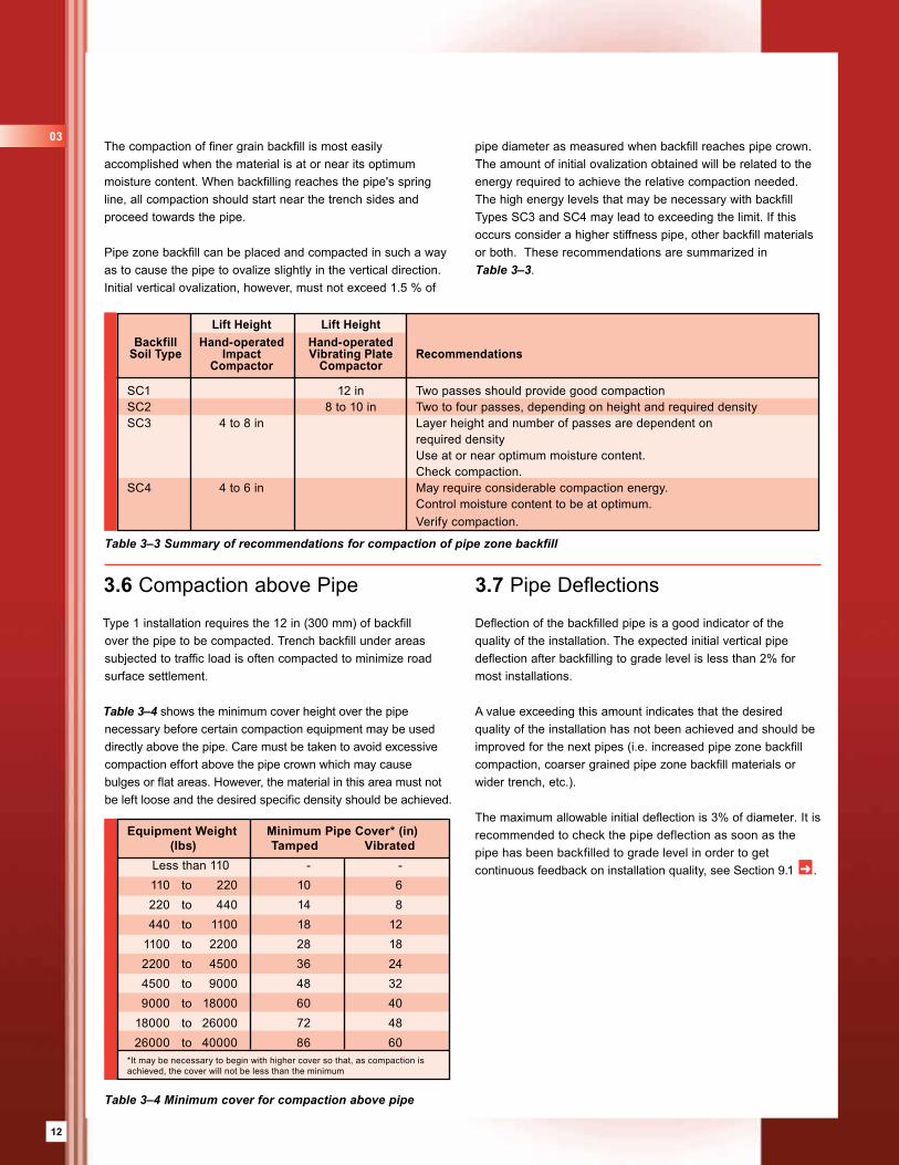
Table 3–4 Minimum cover for compaction above pipe
3.7 Pipe Deflections
Deflection of the backfilled pipe is a good indicator of the quality of the installation. The expected initial vertical pipe deflection after backfilling to grade level is less than 2% for most installations.
A value exceeding this amount indicates that the desired quality of the installation has not been achieved and should be improved for the next pipes (i.e. increased pipe zone backfill compaction, coarser grained pipe zone backfill materials or wider trench, etc.).
The maximum allowable initial deflection is 3% of diameter. It is recommended to check the pipe deflection as soon as the pipe has been backfilled to grade level in order to get continuous feedback on installation quality, see Section 9.1 ➜ .
Table 3–3 Summary of recommendations for compaction of pipe zone backfill
pipe diameter as measured when backfill reaches pipe crown. The amount of initial ovalization obtained will be related to the energy required to achieve the relative compaction needed. The high energy levels that may be necessary with backfill Types SC3 and SC4 may lead to exceeding the limit. If this occurs consider a higher stiffness pipe, other backfill materials or both. These recommendations are summarized in Table 3–3.
Lift Height Lift Height Backfill Hand-operated Hand-operated Soil Type Impact Vibrating Plate Recommendations Compactor Compactor
SC1 12 in Two passes should provide good compactionSC2 8 to 10 in Two to four passes, depending on height and required densitySC3 4 to 8 in Layer height and number of passes are dependent on required density Use at or near optimum moisture content. Check compaction.SC4 4 to 6 in May require considerable compaction energy. Control moisture content to be at optimum. Verify compaction.
03
Equipment Weight Minimum Pipe Cover* (in) (lbs) Tamped Vibrated Less than 110 - - 110 to 220 10 6 220 to 440 14 8 440 to 1100 18 12 1100 to 2200 28 18 2200 to 4500 36 24 4500 to 9000 48 32 9000 to 18000 60 40 18000 to 26000 72 48 26000 to 40000 86 60*It may be necessary to begin with higher cover so that, as compaction is achieved, the cover will not be less than the minimum
3.6 Compaction above Pipe
Type 1 installation requires the 12 in (300 mm) of backfill over the pipe to be compacted. Trench backfill under areas subjected to traffic load is often compacted to minimize road surface settlement.
Table 3–4 shows the minimum cover height over the pipe necessary before certain compaction equipment may be used directly above the pipe. Care must be taken to avoid excessive compaction effort above the pipe crown which may cause bulges or flat areas. However, the material in this area must not be left loose and the desired specific density should be achieved.
13
FLOWTITE pipe sections are typically joined using FLOWTITE couplings. Pipe and couplings may be supplied separately or the pipe may be supplied with a coupling installed on one end. If the couplings are not delivered pre-mounted, it is recommended that they be mounted at the storage yard or at the trench side before the pipe is lowered to the trench bed.The couplings may be supplied with or without a rubber center stop register. If a center register is not supplied, a home-line will be marked on the pipe as an aid for jointing.
Other joining systems such as flanges, mechanical couplings and lay-up joints may also be used for joining FLOWTITE pipe.
4.1 FLOWTITE Double Bell Couplings
FLOWTITE Pressure Coupling
The following steps (1 to 5) are meant for FLOWTITE Pressure Couplings.
Step 1 Foundation and BeddingThe bed must be over-excavated at each joint location to ensure that the pipe will have continuous support and does not rest on the couplings. The coupling area must be properly bedded and backfilled after the joint assembly is completed.
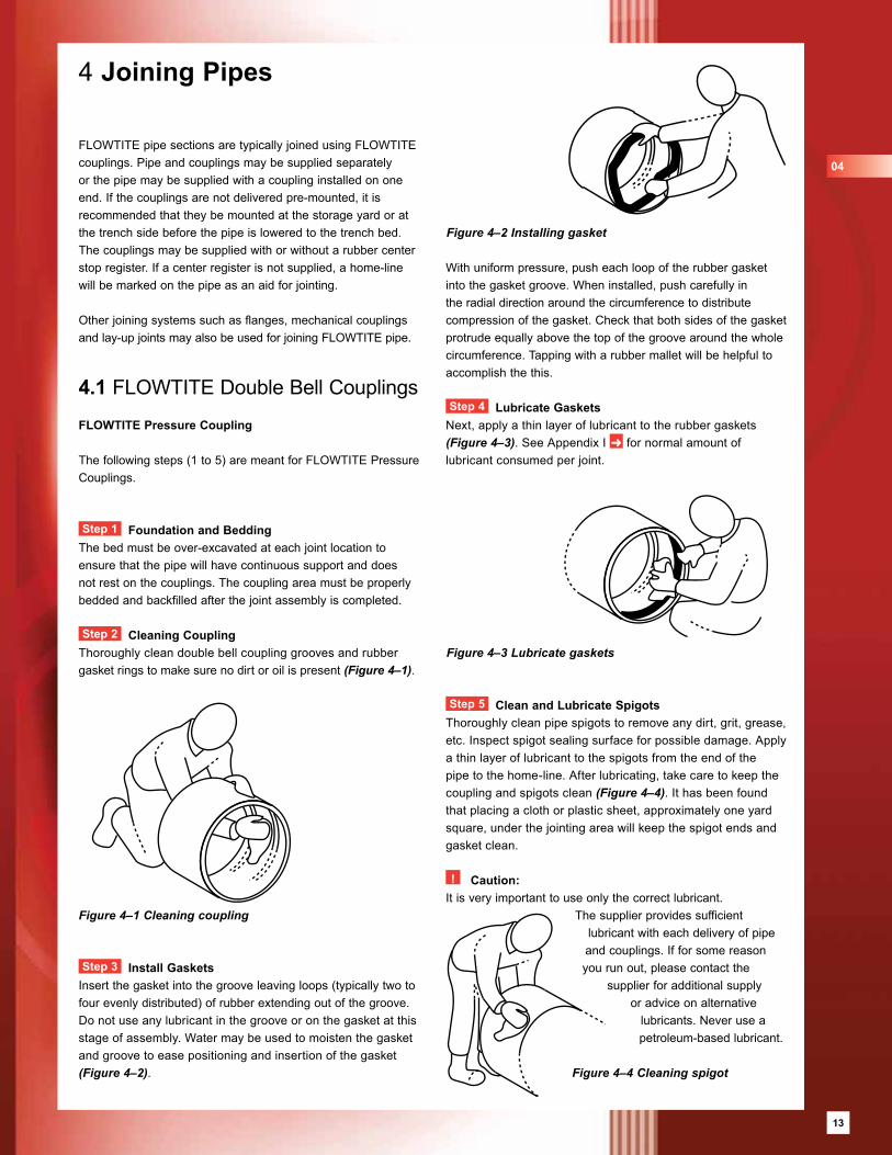
Step 2 Cleaning CouplingThoroughly clean double bell coupling grooves and rubber gasket rings to make sure no dirt or oil is present (Figure 4–1).
Step 3 Install GasketsInsert the gasket into the groove leaving loops (typically two to four evenly distributed) of rubber extending out of the groove. Do not use any lubricant in the groove or on the gasket at this stage of assembly. Water may be used to moisten the gasket and groove to ease positioning and insertion of the gasket (Figure 4–2).
4 Joining Pipes
With uniform pressure, push each loop of the rubber gasket into the gasket groove. When installed, push carefully in the radial direction around the circumference to distribute compression of the gasket. Check that both sides of the gasket protrude equally above the top of the groove around the whole circumference. Tapping with a rubber mallet will be helpful to accomplish the this.
Step 4 Lubricate GasketsNext, apply a thin layer of lubricant to the rubber gaskets (Figure 4–3). See Appendix I ➜ for normal amount of lubricant consumed per joint.
Step 5 Clean and Lubricate SpigotsThoroughly clean pipe spigots to remove any dirt, grit, grease, etc. Inspect spigot sealing surface for possible damage. Apply a thin layer of lubricant to the spigots from the end of the pipe to the home-line. After lubricating, take care to keep the coupling and spigots clean (Figure 4–4). It has been found that placing a cloth or plastic sheet, approximately one yard square, under the jointing area will keep the spigot ends and gasket clean.
! Caution: It is very important to use only the correct lubricant.
The supplier provides sufficient lubricant with each delivery of pipe and couplings. If for some reason you run out, please contact the
supplier for additional supply or advice on alternative
lubricants. Never use a petroleum-based lubricant.
Figure 4–1 Cleaning coupling
Figure 4–2 Installing gasket
Figure 4–3 Lubricate gaskets
04
Figure 4–4 Cleaning spigot
13
14
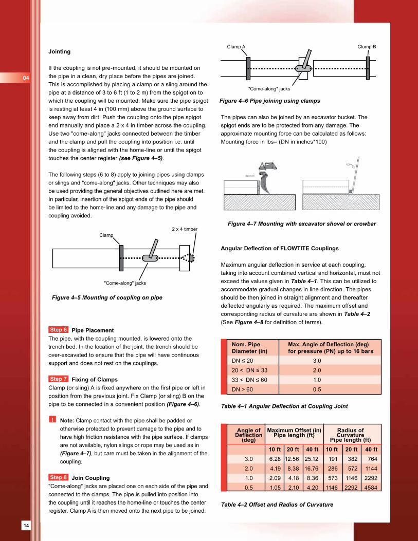
Jointing
If the coupling is not pre-mounted, it should be mounted on the pipe in a clean, dry place before the pipes are joined. This is accomplished by placing a clamp or a sling around the pipe at a distance of 3 to 6 ft (1 to 2 m) from the spigot on to which the coupling will be mounted. Make sure the pipe spigot is resting at least 4 in (100 mm) above the ground surface to keep away from dirt. Push the coupling onto the pipe spigot end manually and place a 2 x 4 in timber across the coupling. Use two "come-along" jacks connected between the timber and the clamp and pull the coupling into position i.e. until the coupling is aligned with the home-line or until the spigot touches the center register (see Figure 4–5).
The following steps (6 to 8) apply to joining pipes using clamps or slings and "come-along" jacks. Other techniques may also be used providing the general objectives outlined here are met. In particular, insertion of the spigot ends of the pipe should be limited to the home-line and any damage to the pipe and coupling avoided.
Step 6 Pipe PlacementThe pipe, with the coupling mounted, is lowered onto the trench bed. In the location of the joint, the trench should be over-excavated to ensure that the pipe will have continuous support and does not rest on the couplings.
Step 7 Fixing of ClampsClamp (or sling) A is fixed anywhere on the first pipe or left in position from the previous joint. Fix Clamp (or sling) B on the pipe to be connected in a convenient position (Figure 4–6).
! Note: Clamp contact with the pipe shall be padded or otherwise protected to prevent damage to the pipe and to have high friction resistance with the pipe surface. If clamps are not available, nylon slings or rope may be used as in (Figure 4–7), but care must be taken in the alignment of the coupling.
Step 8 Join Coupling"Come-along" jacks are placed one on each side of the pipe and connected to the clamps. The pipe is pulled into position into the coupling until it reaches the home-line or touches the center register. Clamp A is then moved onto the next pipe to be joined.
Table 4–2 Offset and Radius of Curvature
Angular Deflection of FLOWTITE Couplings
Maximum angular deflection in service at each coupling, taking into account combined vertical and horizontal, must not exceed the values given in Table 4–1. This can be utilized to accommodate gradual changes in line direction. The pipes should be then joined in straight alignment and thereafter deflected angularly as required. The maximum offset and corresponding radius of curvature are shown in Table 4–2 (See Figure 4–8 for definition of terms).
Table 4–1 Angular Deflection at Coupling Joint
Figure 4–7 Mounting with excavator shovel or crowbar
The pipes can also be joined by an excavator bucket. The spigot ends are to be protected from any damage. The approximate mounting force can be calculated as follows:Mounting force in lbs= (DN in inches*100)
Nom. Pipe Max. Angle of Deflection (deg) Diameter (in) for pressure (PN) up to 16 barsDN ≤ 20 3.0
20 < DN ≤ 33 2.0
33 < DN ≤ 60 1.0
DN > 60 0.5
04
Clamp2 x 4 timber
"Come-along" jacks
Figure 4–5 Mounting of coupling on pipe
Figure 4–6 Pipe joining using clamps
Angle of Maximum Offset (in) Radius of Deflection Pipe length (ft) Curvature (deg) Pipe length (ft) 10 ft 20 ft 40 ft 10 ft 20 ft 40 ft 3.0 6.28 12.56 25.12 191 382 764
2.0 4.19 8.38 16.76 286 572 1144
1.0 2.09 4.18 8.36 573 1146 2292
0.5 1.05 2.10 4.20 1146 2292 4584
"Come-along" jacks
Clamp A Clamp B

15
Angular deflected coupling joints are stabilized by the stiffness of the soil surrounding the pipe and coupling. Pressure pipes PN > 15 psi (1 bar) should have angularly rotated joints backfilled to minimum 90% standard proctor compaction. Coupling joints that are placed with vertical angular rotation, where the direction of the thrust is upward, should be backfilled to a minimum cover depth of 4 ft (1.2 m) for operating pressures of 225 psi (16 bar) and greater.
Pipe Misalignment
To maintain joint recommended tightness, the maximum allowable misalignment of adjacent pipe ends is 0.2 in (5 mm) – see Figure 4–9. It is recommended the misalignment be monitored near thrust blocks, valve chambers and similar structures, and at closure or repair locations.
Figure 4–8 FLOWTITE coupling, angular joint deflection
4.2 Restrained Joints
The FLOWTITE locked joint is a double bell with rubber gaskets and locking rods to transfer axial thrust from one pipe section to another. On each side, the coupling bell has a standard rubber gasket and a rod-groove system, through which the load is transferred via compressive and shear action. The pipe spigot for locked joints has a matching groove.
The joint is assembled by using a similar procedure as the standard FLOWTITE pressure coupling, except that there is no center register. Steps 1 through 6 above should be followed. For step 7 the pipe is pulled into position until the groove in the pipe is visible through the opening in the coupling. The locking rod is, then, pushed into position with a hammer.
4.3 Flanged JointsContact Moulded
GRP flanges should be joined according to the following procedure: (Figure 4–11)
1 Thoroughly clean the flange face and the O-ring groove.
2 Ensure the sealing gasket is clean and undamaged.
3 Position sealing gasket in groove.
4 Align flanges to be joined.
5 Insert bolts, washers and nuts. All hardware must be clean and lubricated to avoid incorrect tightening. Washers must be used on all GRP flanges.
6 Using a torque wrench, tighten all bolts to 25 ft-lb (35 Nm) torque, following standard flange bolt tightening sequences.
7 Repeat this procedure, raising the bolt torque to 50 ft-lb (70 Nm), or until the flanges touch at their inside
edges. Do not exceed this torque. To do so may cause permanent damage to GRP flanges.
8 Check bolt torques one hour later and adjust if necessary to 50 ft-lb (70 Nm).
Coupling
Offset
Radius ofcurvature
Deflectionangle
Pipe
Figure 4–9 Misalignment
Misalignment
Figure 4–11 Flanged joint
MetalFlange
FiberglassFlange
‘O’ Ring Gasket
Figure 4–10 FLOWTITE locked joint
Gasket Nylon locking rod
04
15
16
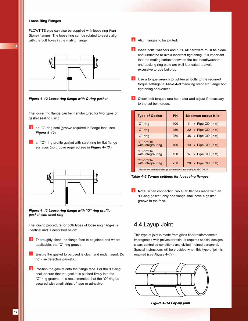
Loose Ring Flanges
FLOWTITE pipe can also be supplied with loose ring (Van Stone) flanges. The loose ring can be rotated to easily align with the bolt holes in the mating flange.
The loose ring flange can be manufactured for two types of gasket sealing using
1 an “O”-ring seal (groove required in flange face, see Figure 4–12)
an “O”-ring profile gasket with steel ring for flat flange surfaces (no groove required see in Figure 4–13.)
The joining procedure for both types of loose ring flanges is identical and is described below.
1 Thoroughly clean the flange face to be joined and where applicable, the “O”-ring groove.
Ensure the gasket to be used is clean and undamaged. Do not use defective gaskets.
3 Position the gasket onto the flange face. For the “O”-ring seal, ensure that the gasket is pushed firmly into the “O”-ring groove. It is recommended that the “O”-ring be secured with small strips of tape or adhesive.
4.4 Layup Joint
This type of joint is made from glass fiber reinforcements impregnated with polyester resin. It requires special designs, clean, controlled conditions and skilled, trained personnel. Special instructions will be provided when this type of joint is required (see Figure 4–14).
Figure 4–14 Lay-up joint
Figure 4–13 Loose ring flange with "O"-ring profile gasket with steel ring
4 Align flanges to be jointed.
5 Insert bolts, washers and nuts. All hardware must be clean and lubricated to avoid incorrect tightening. It is important that the mating surface between the bolt head/washers and backing ring plate are well lubricated to avoid excessive torque build-up.
6 Use a torque wrench to tighten all bolts to the required torque settings in Table 4–3 following standard flange bolt tightening sequences.
7 Check bolt torques one hour later and adjust if necessary to the set bolt torque.
! Note: When connecting two GRP flanges made with an “O”-ring gasket, only one flange shall have a gasket groove in the face.
Table 4–3 Torque settings for loose ring flanges
Type of Gasket PN Maximum torque ft-lb*
“O”-ring 100 11 x Pipe OD (in ft)
“O”-ring 150 22 x Pipe OD (in ft)
“O”-ring 250 45 x Pipe OD (in ft)
“O”-profile with integral ring 100 10 x Pipe OD (in ft)
“O”-profilewith integral ring 150 17 x Pipe OD (in ft)
“O”-profile with integral ring 250 20 x Pipe OD (in ft)
* Based on standard flange dimensions according to ISO 7005
Figure 4–12 Loose ring flange with O-ring gasket
04
17
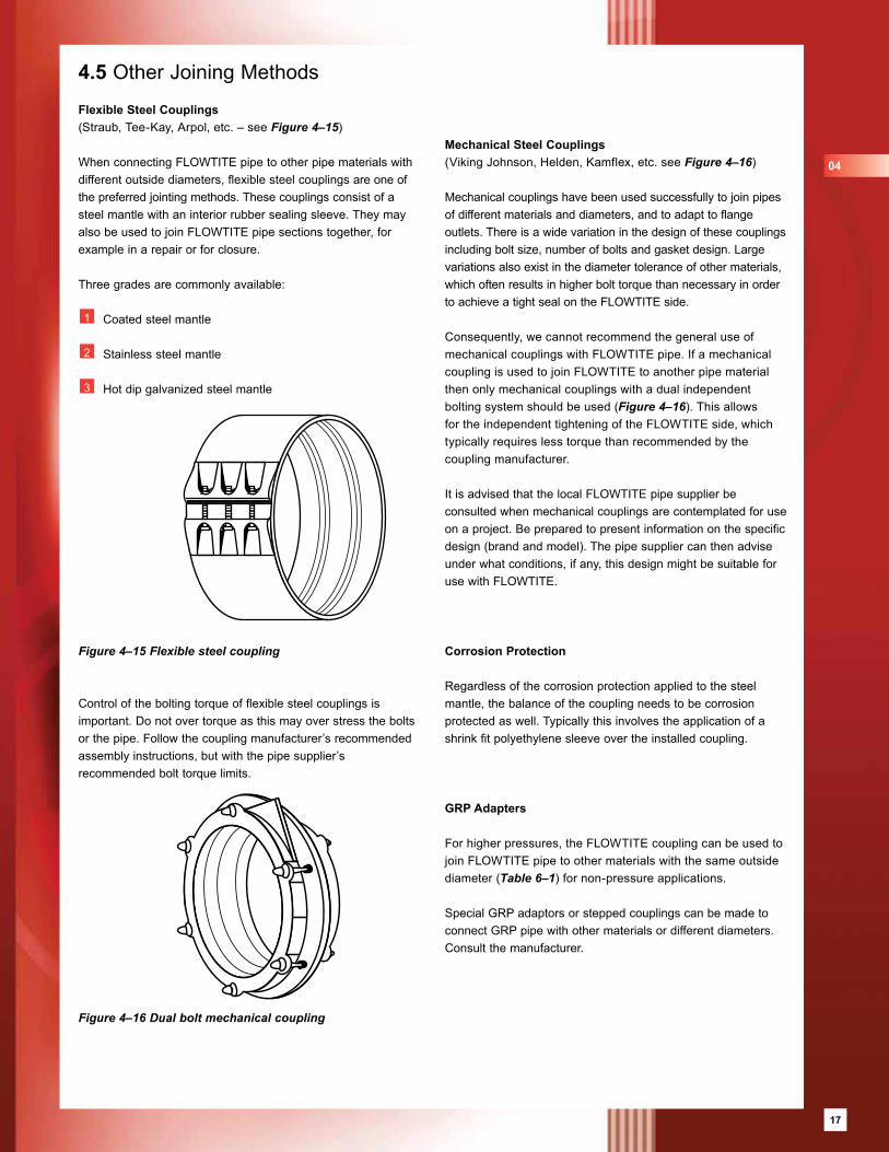
4.5 Other Joining Methods
Flexible Steel Couplings(Straub, Tee-Kay, Arpol, etc. – see Figure 4–15)
When connecting FLOWTITE pipe to other pipe materials with different outside diameters, flexible steel couplings are one of the preferred jointing methods. These couplings consist of a steel mantle with an interior rubber sealing sleeve. They may also be used to join FLOWTITE pipe sections together, for example in a repair or for closure.
Three grades are commonly available: 1 Coated steel mantle
2 Stainless steel mantle
3 Hot dip galvanized steel mantle
Control of the bolting torque of flexible steel couplings is important. Do not over torque as this may over stress the bolts or the pipe. Follow the coupling manufacturer’s recommended assembly instructions, but with the pipe supplier’s recommended bolt torque limits.
Mechanical Steel Couplings(Viking Johnson, Helden, Kamflex, etc. see Figure 4–16)
Mechanical couplings have been used successfully to join pipes of different materials and diameters, and to adapt to flange outlets. There is a wide variation in the design of these couplings including bolt size, number of bolts and gasket design. Large variations also exist in the diameter tolerance of other materials, which often results in higher bolt torque than necessary in order to achieve a tight seal on the FLOWTITE side.
Consequently, we cannot recommend the general use of mechanical couplings with FLOWTITE pipe. If a mechanical coupling is used to join FLOWTITE to another pipe material then only mechanical couplings with a dual independent bolting system should be used (Figure 4–16). This allows for the independent tightening of the FLOWTITE side, which typically requires less torque than recommended by the coupling manufacturer.
It is advised that the local FLOWTITE pipe supplier be consulted when mechanical couplings are contemplated for use on a project. Be prepared to present information on the specific design (brand and model). The pipe supplier can then advise under what conditions, if any, this design might be suitable for use with FLOWTITE.
Corrosion Protection
Regardless of the corrosion protection applied to the steel mantle, the balance of the coupling needs to be corrosion protected as well. Typically this involves the application of a shrink fit polyethylene sleeve over the installed coupling.
GRP Adapters
For higher pressures, the FLOWTITE coupling can be used to join FLOWTITE pipe to other materials with the same outside diameter (Table 6–1) for non-pressure applications.
Special GRP adaptors or stepped couplings can be made to connect GRP pipe with other materials or different diameters. Consult the manufacturer.
Figure 4–15 Flexible steel coupling
Figure 4–16 Dual bolt mechanical coupling
04
17
18
5 Thrust Restraints, Concrete Encasement and Connections to Rigid Structures
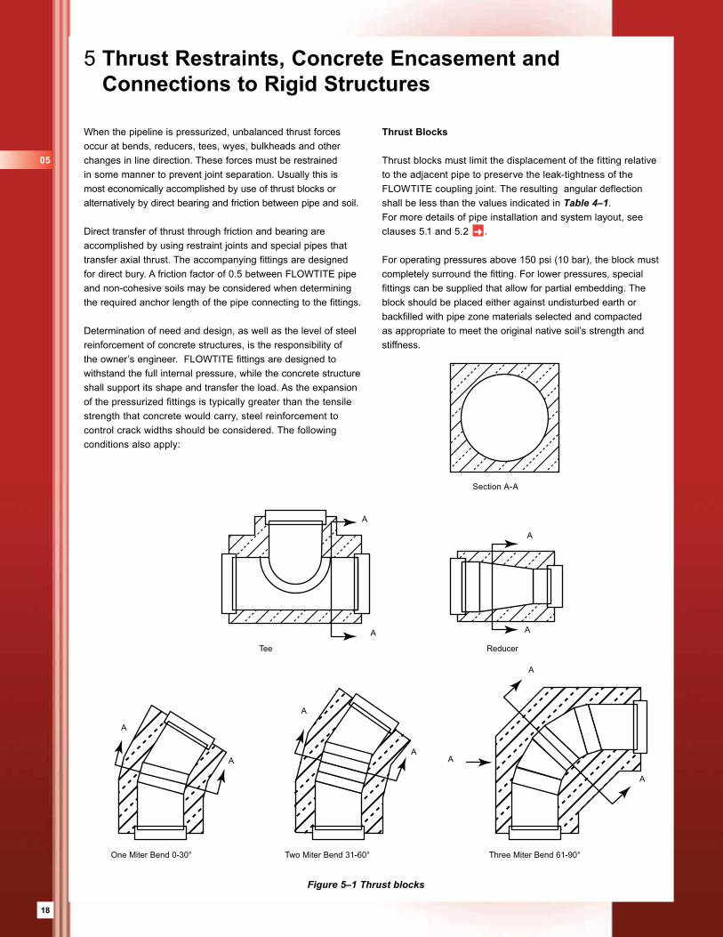
When the pipeline is pressurized, unbalanced thrust forces occur at bends, reducers, tees, wyes, bulkheads and other changes in line direction. These forces must be restrained in some manner to prevent joint separation. Usually this is most economically accomplished by use of thrust blocks or alternatively by direct bearing and friction between pipe and soil. Direct transfer of thrust through friction and bearing are accomplished by using restraint joints and special pipes that transfer axial thrust. The accompanying fittings are designed for direct bury. A friction factor of 0.5 between FLOWTITE pipe and non-cohesive soils may be considered when determining the required anchor length of the pipe connecting to the fittings.
Determination of need and design, as well as the level of steel reinforcement of concrete structures, is the responsibility of the owner’s engineer. FLOWTITE fittings are designed to withstand the full internal pressure, while the concrete structure shall support its shape and transfer the load. As the expansion of the pressurized fittings is typically greater than the tensile strength that concrete would carry, steel reinforcement to control crack widths should be considered. The following conditions also apply:
Figure 5–1 Thrust blocks
Thrust Blocks
Thrust blocks must limit the displacement of the fitting relative to the adjacent pipe to preserve the leak-tightness of the FLOWTITE coupling joint. The resulting angular deflection shall be less than the values indicated in Table 4–1. For more details of pipe installation and system layout, see clauses 5.1 and 5.2 ➜ .
For operating pressures above 150 psi (10 bar), the block must completely surround the fitting. For lower pressures, special fittings can be supplied that allow for partial embedding. The block should be placed either against undisturbed earth or backfilled with pipe zone materials selected and compacted as appropriate to meet the original native soil’s strength and stiffness.
Section A-A
One Miter Bend 0-30° Two Miter Bend 31-60°
Tee Reducer
Three Miter Bend 61-90°
A
A
A
A
A
A A
A
A
A
A
05
19
Valves
Valves must be sufficiently anchored to absorb the pressure thrust. More details on valves and chambers are provided in section 8.
Nozzles
Nozzles are tee branches meeting all of the following criteria:
1 Nozzle diameter ≤ 12 in (300 mm).
Header diameter ≥ 3 times nozzle diameter.
! Note: it is not necessary to encase nozzle connections in concrete.
5.1 Concrete Encasement
When pipes (or fittings) must be encased in concrete, such as for thrust blocks, stress blocks, or to carry unusual loads, specific additions to the installation procedures must be observed.
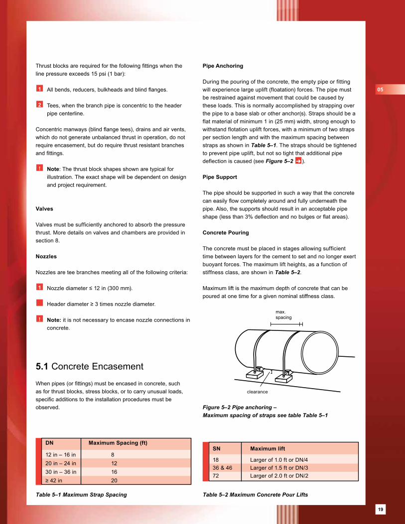
Pipe Anchoring
During the pouring of the concrete, the empty pipe or fitting will experience large uplift (floatation) forces. The pipe must be restrained against movement that could be caused by these loads. This is normally accomplished by strapping over the pipe to a base slab or other anchor(s). Straps should be a flat material of minimum 1 in (25 mm) width, strong enough to withstand flotation uplift forces, with a minimum of two straps per section length and with the maximum spacing between straps as shown in Table 5–1. The straps should be tightened to prevent pipe uplift, but not so tight that additional pipe deflection is caused (see Figure 5–2 ➜ ).
Pipe Support
The pipe should be supported in such a way that the concrete can easily flow completely around and fully underneath the pipe. Also, the supports should result in an acceptable pipe shape (less than 3% deflection and no bulges or flat areas).
Concrete Pouring
The concrete must be placed in stages allowing sufficient time between layers for the cement to set and no longer exert buoyant forces. The maximum lift heights, as a function of stiffness class, are shown in Table 5–2.
Maximum lift is the maximum depth of concrete that can be poured at one time for a given nominal stiffness class.
Figure 5–2 Pipe anchoring – Maximum spacing of straps see table Table 5–1
Table 5–1 Maximum Strap Spacing Table 5–2 Maximum Concrete Pour Lifts
Thrust blocks are required for the following fittings when the line pressure exceeds 15 psi (1 bar):
1 All bends, reducers, bulkheads and blind flanges. 2 Tees, when the branch pipe is concentric to the header
pipe centerline.
Concentric manways (blind flange tees), drains and air vents, which do not generate unbalanced thrust in operation, do not require encasement, but do require thrust resistant branches and fittings.
! Note: The thrust block shapes shown are typical for illustration. The exact shape will be dependent on design and project requirement.
max. spacing
clearance
DN Maximum Spacing (ft)
12 in – 16 in 820 in – 24 in 1230 in – 36 in 16≥ 42 in 20
SN Maximum lift
18 Larger of 1.0 ft or DN/436 & 46 Larger of 1.5 ft or DN/372 Larger of 2.0 ft or DN/2
05
19
20
5.2 Connections to Rigid Structures
Excessive bending and shear stresses can develop in a pipe that moves excessively in relation to a rigid structure. Situations where this may occur are when a pipe passes through a wall (e.g. valve chamber or manhole), is encased in concrete (e.g. thrust block), or is flanged to a pump, valve or other structure.
For all connections to rigid structures action must be taken by the installer to minimize the development of high discontinuity stresses in the pipe. Angular deflection and misalignment at joints close to thrust blocks shall be avoided during installation. Two options are available. The standard (preferred) uses a coupling joint cast into the concrete-pipe interface. The alternate wraps the pipe in rubber to ease the transition.
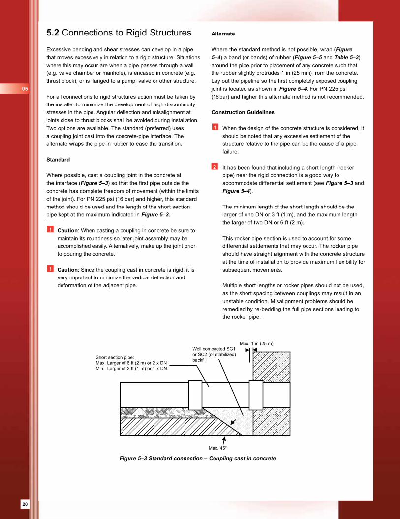
Standard
Where possible, cast a coupling joint in the concrete at the interface (Figure 5–3) so that the first pipe outside the concrete has complete freedom of movement (within the limits of the joint). For PN 225 psi (16 bar) and higher, this standard method should be used and the length of the short section pipe kept at the maximum indicated in Figure 5–3.
! Caution: When casting a coupling in concrete be sure to maintain its roundness so later joint assembly may be accomplished easily. Alternatively, make up the joint prior to pouring the concrete.
! Caution: Since the coupling cast in concrete is rigid, it is very important to minimize the vertical deflection and deformation of the adjacent pipe.
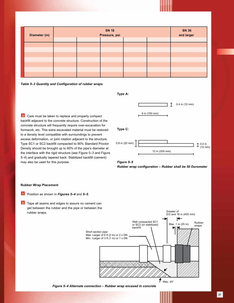
Alternate
Where the standard method is not possible, wrap (Figure 5–4) a band (or bands) of rubber (Figure 5–5 and Table 5–3) around the pipe prior to placement of any concrete such that the rubber slightly protrudes 1 in (25 mm) from the concrete. Lay out the pipeline so the first completely exposed coupling joint is located as shown in Figure 5–4. For PN 225 psi (16 bar) and higher this alternate method is not recommended.
Construction Guidelines
1 When the design of the concrete structure is considered, it should be noted that any excessive settlement of the structure relative to the pipe can be the cause of a pipe failure.
2 It has been found that including a short length (rocker pipe) near the rigid connection is a good way to accommodate differential settlement (see Figure 5–3 and Figure 5–4).
The minimum length of the short length should be the larger of one DN or 3 ft (1 m), and the maximum length the larger of two DN or 6 ft (2 m).
This rocker pipe section is used to account for some differential settlements that may occur. The rocker pipe should have straight alignment with the concrete structure at the time of installation to provide maximum flexibility for subsequent movements.
Multiple short lengths or rocker pipes should not be used, as the short spacing between couplings may result in an unstable condition. Misalignment problems should be remedied by re-bedding the full pipe sections leading to the rocker pipe.
Figure 5–3 Standard connection – Coupling cast in concrete
Short section pipe:Max. Larger of 6 ft (2 m) or 2 x DNMin. Larger of 3 ft (1 m) or 1 x DN
Well compacted SC1or SC2 (or stabilized)backfill
Max. 1 in (25 m)
Max. 45°
05
21
Figure 5–4 Alternate connection – Rubber wrap encased in concrete
Table 5–3 Quantity and Configuration of rubber wraps
Rubber Wrap Placement
1 Position as shown in Figures 5–4 and 5–5.
2 Tape all seams and edges to assure no cement can get between the rubber and the pipe or between the
rubber wraps.
3 Care must be taken to replace and properly compact backfill adjacent to the concrete structure. Construction of the concrete structure will frequently require over-excavation for formwork, etc. This extra excavated material must be restored to a density level compatible with surroundings to prevent excess deformation, or joint rotation adjacent to the structure. Type SC1 or SC2 backfill compacted to 90% Standard Proctor Density should be brought up to 60% of the pipe’s diameter at the interface with the rigid structure (see Figure 5–3 and Figure 5–4) and gradually tapered back. Stabilized backfill (cement) may also be used for this purpose.
Well compacted SC1or SC2 (or stabilized)backfill
Rubberwraps
Greater ofD/2 and 16 in (400 mm)
Max. 45°
Figure 5–5 Rubber wrap configuration – Rubber shall be 50 Durometer
Type A:
Type C:
6 in (150 mm)
0.4 in (10 mm)
0.4 in (10 mm)
0.8 in (20 mm)
12 in (300 mm)
SN 18 SN 36 Diameter (in) Pressure, psi and larger
Short section pipe:Max. Larger of 6 ft (2 m) or 2 x DNMin. Larger of 3 ft (1 m) or 1 x DN
Max. 1 in (25 m)
21
22
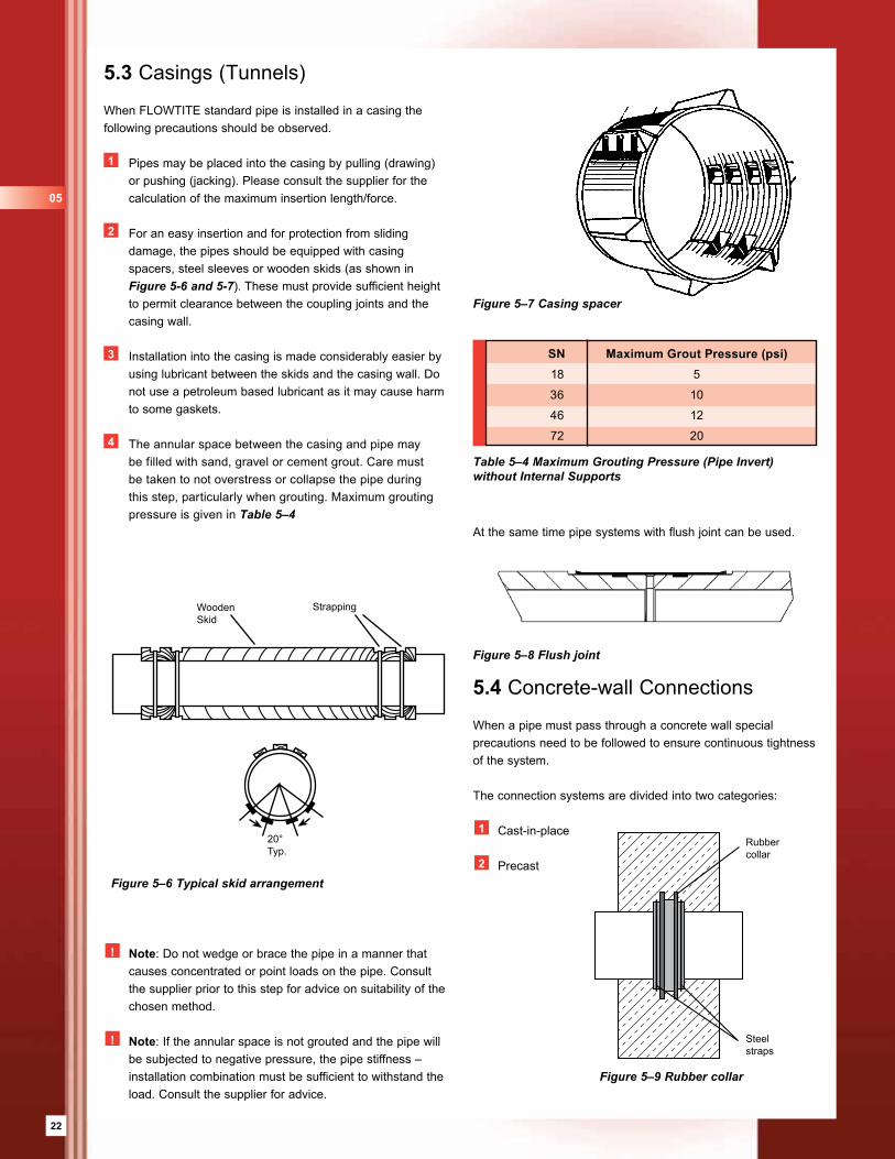
Table 5–4 Maximum Grouting Pressure (Pipe Invert) without Internal Supports
SN Maximum Grout Pressure (psi) 18 5
36 10
46 12
72 20
Figure 5–7 Casing spacer
! Note: Do not wedge or brace the pipe in a manner that causes concentrated or point loads on the pipe. Consult the supplier prior to this step for advice on suitability of the chosen method.
! Note: If the annular space is not grouted and the pipe will be subjected to negative pressure, the pipe stiffness – installation combination must be sufficient to withstand the load. Consult the supplier for advice.
5.3 Casings (Tunnels)
When FLOWTITE standard pipe is installed in a casing the following precautions should be observed.
1 Pipes may be placed into the casing by pulling (drawing) or pushing (jacking). Please consult the supplier for the calculation of the maximum insertion length/force.
2 For an easy insertion and for protection from sliding damage, the pipes should be equipped with casing spacers, steel sleeves or wooden skids (as shown in Figure 5-6 and 5-7). These must provide sufficient height to permit clearance between the coupling joints and the casing wall.
3 Installation into the casing is made considerably easier by using lubricant between the skids and the casing wall. Do not use a petroleum based lubricant as it may cause harm to some gaskets.
4 The annular space between the casing and pipe may be filled with sand, gravel or cement grout. Care must be taken to not overstress or collapse the pipe during this step, particularly when grouting. Maximum grouting pressure is given in Table 5–4
Figure 5–6 Typical skid arrangement
Wooden Skid
Strapping
20°Typ.
At the same time pipe systems with flush joint can be used.
5.4 Concrete-wall Connections
When a pipe must pass through a concrete wall special precautions need to be followed to ensure continuous tightness of the system.
The connection systems are divided into two categories:
1 Cast-in-place
2 Precast
Figure 5–9 Rubber collar
Rubbercollar
Steel straps
Figure 5–8 Flush joint
05
23
Cast-in-place
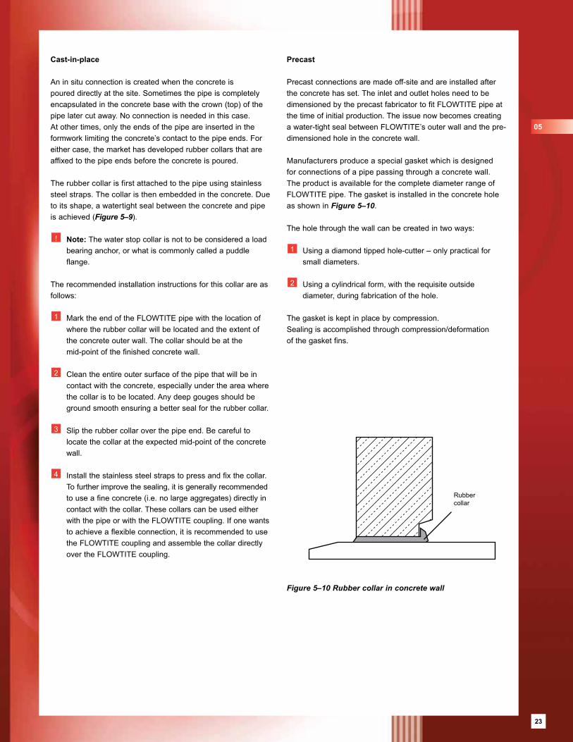
An in situ connection is created when the concrete is poured directly at the site. Sometimes the pipe is completely encapsulated in the concrete base with the crown (top) of the pipe later cut away. No connection is needed in this case. At other times, only the ends of the pipe are inserted in the formwork limiting the concrete’s contact to the pipe ends. For either case, the market has developed rubber collars that are affixed to the pipe ends before the concrete is poured.
The rubber collar is first attached to the pipe using stainless steel straps. The collar is then embedded in the concrete. Due to its shape, a watertight seal between the concrete and pipe is achieved (Figure 5–9).
! Note: The water stop collar is not to be considered a load bearing anchor, or what is commonly called a puddle flange.
The recommended installation instructions for this collar are as follows:
1 Mark the end of the FLOWTITE pipe with the location of where the rubber collar will be located and the extent of the concrete outer wall. The collar should be at the
mid-point of the finished concrete wall.
2 Clean the entire outer surface of the pipe that will be in contact with the concrete, especially under the area where the collar is to be located. Any deep gouges should be ground smooth ensuring a better seal for the rubber collar.
3 Slip the rubber collar over the pipe end. Be careful to locate the collar at the expected mid-point of the concrete wall.
4 Install the stainless steel straps to press and fix the collar. To further improve the sealing, it is generally recommended to use a fine concrete (i.e. no large aggregates) directly in contact with the collar. These collars can be used either with the pipe or with the FLOWTITE coupling. If one wants to achieve a flexible connection, it is recommended to use the FLOWTITE coupling and assemble the collar directly over the FLOWTITE coupling.
Precast
Precast connections are made off-site and are installed after the concrete has set. The inlet and outlet holes need to be dimensioned by the precast fabricator to fit FLOWTITE pipe at the time of initial production. The issue now becomes creating a water-tight seal between FLOWTITE’s outer wall and the pre-dimensioned hole in the concrete wall.
Manufacturers produce a special gasket which is designed for connections of a pipe passing through a concrete wall. The product is available for the complete diameter range of FLOWTITE pipe. The gasket is installed in the concrete hole as shown in Figure 5–10.
The hole through the wall can be created in two ways:
1 Using a diamond tipped hole-cutter – only practical for small diameters.
2 Using a cylindrical form, with the requisite outside diameter, during fabrication of the hole.
The gasket is kept in place by compression. Sealing is accomplished through compression/deformation of the gasket fins.
Rubbercollar
Figure 5–10 Rubber collar in concrete wall
05
23
24
6 Field Adjustments
6.1 Length Adjustment
A large majority of the pipe supplied by FLOWTITE producers has the outside diameter of the barrel of the pipe within the tolerance range of the calibrated spigot (Table 6–1). These pipes are often marked as Adjustment Pipe or similar. The following procedures will assist in correctly making the length adjustment:
Ensure that the pipe diameter is within the spigot tolerance range.
2 Determine the length required and mark a square cut on the selected pipe.
3 Cut the pipe at the appropriate location using a circular saw with a diamond coated blade. Use proper eye, ear and dust protection. Consult the pipe supplier for recommendations.
4 Clean the surface in the jointing area, sand smooth any rough spots and with a grinder bevel grind the pipe end to ease assembly (see Figure 6–1). No further grinding is necessary.
! Note: Spigot diameters based on cast iron OD diameters
! Note: For field closure section, double the spigot width.
Table 6–1 Spigot Dimensions and Tolerances.
6.2 Field Closures with FLOWTITE Couplings
FLOWTITE couplings can be used for field closures and repairs. The minimum length of the closure pipe should be 3 ft (1 m). In addition, the closure pipe should not be adjacent to a “rocker” pipe, i.e., the short length meant to provide flexibility adjacent to rigid connections (see Figures 5–3 and 5–4 ➜ ).
Procedure
Measure the distance between the pipe ends where you want to set in the closure pipe. The closure pipe should be 0.4 to 0.8 in (10 to 20 mm) shorter than the measured length. The narrower the gap the easier it will be to make the closure.
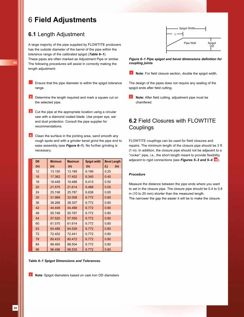
Figure 6–1 Pipe spigot and bevel dimensions definition for coupling joints
Spigot Width
Pipe Wall
L
Spigot OD
The design of the pipes does not require any sealing of the spigot ends after field cutting.
! Note: After field cutting, adjustment pipe must be chamfered.
DN Minimum Maximum Spigot width Bevel Length(in) (in) (in) (in) (L) (in)12 13.150 13.189 6.199 0.2516 17.362 17.402 6.340 0.4018 19.449 19.488 6.413 0.5020 21.575 21.614 6.489 0.5524 25.748 25.787 6.638 0.6530 31.969 32.008 6.772 0.8036 38.268 38.307 6.772 0.8042 44.449 44.488 6.772 0.8048 50.748 50.787 6.772 0.8054 57.520 57.559 6.772 0.8060 61.575 61.614 6.772 0.8063 64.488 64.528 6.772 0.8072 72.402 72.441 6.772 0.8078 80.433 80.472 6.772 0.8084 88.465 88.504 6.772 0.8096 96.496 96.535 6.772 0.80
06
25
Pipe Selection
Choose a pipe which is within the spigot diameter tolerance. These pipes will have the required spigot outside dimension for joining along the entire pipe length. If possible choose a pipe with the outside dimension at the low end of the spigot range (see Table 6–1).
Pipe Preparation
Mark the pipe length required and make a cut perpen dicular and square to the pipe axis with a circular saw. Use a grinding tool to make a 20 degree bevel on the pipe end and round-off the corners.
Be careful that the remaining thickness on the pipe spigot end is not less than one half the pipe thickness. It is also important to have a minimum chamfer length, L, for guiding the pipe end without damaging the gasket. Follow the recommended lengths in Table 6–1. After bevelling, use sandpaper to remove any sharp corners on the pipe surface which may have been caused by the cutting. Smooth the spigot of any rough spots.
! Note: The spigot width must be at least equal to the coupling width. This will be twice the values shown in
Table 6–1.
Please make sure that the surface has no grooves, and that the spigot OD is within the limits shown in Table 6–1.
Installation
1 Select two couplings, remove the center registers, and leave the gaskets in place. Clean the couplings if necessary. The gasket groove must be free of dirt to allow unrestricted deformation of the gasket.
2 Lubricate carefully, including between the gasket fins.
3 Also, lubricate the clean spigot ends of the closure pipes with a thin continuous layer of lubricant, bevelled surface.
4 Place one coupling square onto the end of the closure pipe so that the gasket is in contact around its entire circumference. Push or pull the coupling uniformly onto the closure pipe until the entire coupling is resting on the spigot end. It may be necessary to gently help the second ring over the chamfered end of the pipes. Repeat with the second coupling on the other end.
5 Mark home-lines onto the adjacent pipe spigot ends to control the uniform backward movement of the coupling. The home-line’s location is calculated as follows:
HL = (Wc-Wg)/2 HL – home-line Wc – width of the coupling Wg – width of gap between closure pipe and adjacent pipe (measured).
2 Set the closure pipe in the trench aligned with the adjacent pipes and with equal clearance on either side. Any angle or tilt will complicate the assembling process.
7 Clean the spigot ends of the adjacent pipes and lubricate with an even, thin layer. Install special tools to pull the coupling back to closing position. (Consult your supplier for information about the tools). It is recommended that you pull the couplings over both sides simultaneously; keep the closure pipe centered and minimize pipe end contact. Stop pulling when the coupling’s edge touches the home-line. For man-entry size pipes, an individual inside the pipe watching the assembly process can be advantageous.
8 The compaction of the backfill around a field closure pipe is very important and should be no less than 90% SPD. Often the closure area is over excavated for ease of access. This is recommended to prevent excessive movement and joint rotations.
! Note: After the coupling is in final position, a feeler gauge may be used to assure that gasket lips are properly oriented.
6.3 Field Closures with Non-FLOWTITE Couplings
Follow the general procedures of section 6.2 ➜ except that the closure pipe will not typically need to have the special long machined spigot ends.
The installation procedures for the particular coupling used must be followed (see section 4.5 ➜ ).
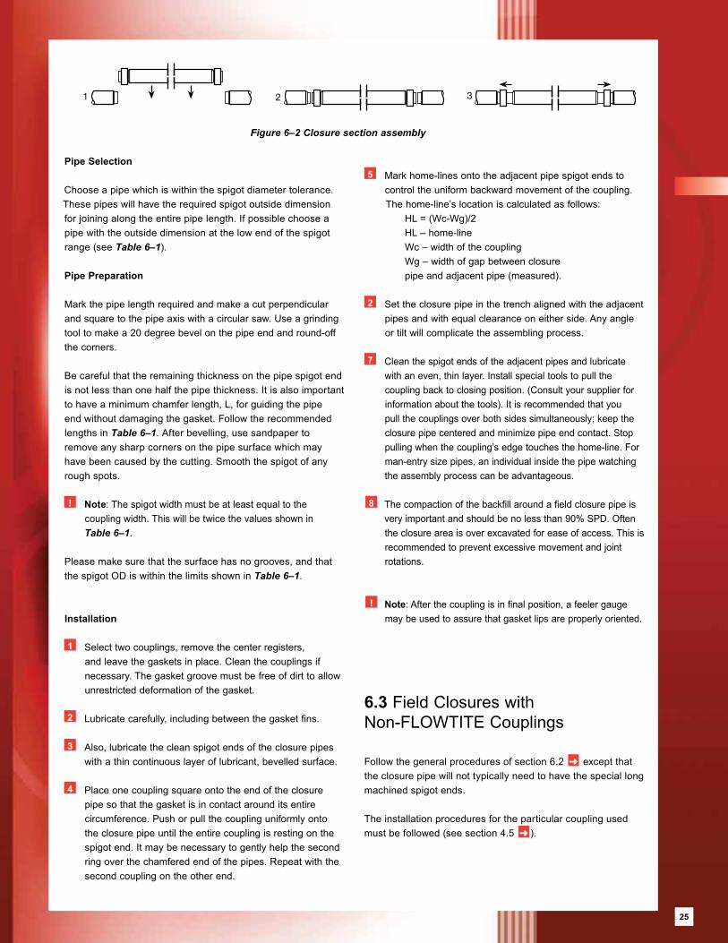
Figure 6–2 Closure section assembly
1
2
3
1
2
3
1
2
3
25
26
7 Other Installation Procedures and Considerations
7.1 Multiple Pipes in Same Trench
When two or more pipes are installed parallel in the same trench, clear spacing between the pipes should be as shown in Figure 7–1. Space between pipe and trench wall should be as shown in Figure 3–1.
It is advisable when laying pipes of different diameters in the same trench to lay them with the same invert elevation. When this is not possible, use backfill material type SC1 or SC2 to fill all the space from the trench bottom to the invert of the higher pipe. Proper compaction must be achieved (min 90% SPD).
7.3 Unstable Trench Bottom
Where the trench bottom has soft, loose or highly expansive soils, it is regarded as unstable. An unstable trench bottom must be stabilized before laying pipe or a foundation must be constructed to minimize differential settlement of the trench bottom. A well graded sandy gravel compacted to 90% SPD or crushed stone is recommended for use in foundation layers.
The depth of the sandy gravel or crushed stone material used for foundation depends upon the severity of the trench bottom soil conditions, but should not be less than 6 in (150 mm).
The normal bedding must be placed on top of such foundations. When crushed rock is used, the use of filter cloth to completely surround the foundation material will prevent foundation and bedding materials from migrating into one another which could cause loss of pipe bottom support. Filter cloth is not needed if the same material is used for foundation and bed, or if graded sandy gravel is used for the foundation. Additionally, the maximum pipe section length between flexible joints shall be 20 ft (6 m).
7.2 Cross-Overs
When two pipes cross, so that one passes over the other, vertical spacing between pipes and installation of the bottom pipe should be as shown in Figure 7–2.
In some cases, it is necessary to lay a pipe under an existing line. Extra care should be taken not to damage the existing pipe. It should be protected by fastening it to a steel beam crossing the trench. It is also advisable to wrap the pipe in order to protect it from impact damage.
Figure 7–1 Spacing between pipes in the same trench
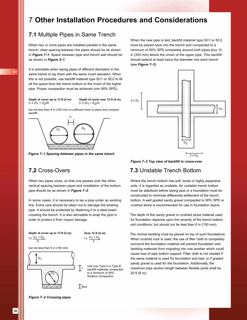
Figure 7–3 Top view of backfill in cross-over.
Depth of cover up to 13 ft (4 m): Depth of cover over 13 ft (4 m):C ≥ (D1 + D2)/6 C ≥ (D1 + D2)/4
but not less than 6 in (150 mm) or sufficient room to place and compact backfill
C
D1D2
Figure 7–2 Crossing pipes
Depth of cover up to 13 ft (4 m):
f ≥ D1 + D2 6
but not less than 6 in (150 mm)
Over 13 ft (4 m):
f ≥ D1 + D2 4
D1
D2
f
Bed
Use only Type A or Type Bbackfill materials compactedto a minimum of 90%Relative Compaction
D2
D1
2 x D2
2 x D1
When the new pipe is laid, backfill material type SC1 or SC2 must be placed back into the trench and compacted to a minimum of 90% SPD completely around both pipes plus 12 in (300 mm) above the crown of the upper pipe. This backfill should extend at least twice the diameter into each trench (see Figure 7–3).
07
27
7.4 Flooded Trench
When the groundwater table is above the trench bottom, the water level must be lowered to at least the trench bottom (preferably about 8 in (200 mm) below) prior to preparation of the bed. Different techniques may be used depending on the nature of the native material.
For sandy or silty soils, a system of well-points to a header pipe and a pump is recommended. The spacing between individual well-points and the depth at which they will be driven depends on the groundwater table and the permeability of the soil. It is important to use a filter around the suction point (coarse sand or gravel) to prevent clogging of the well-points by fine grained native material.
When the native material consists of clay or bedrock, well-points will not work. Dewatering is more difficult to achieve in this case. The use of sumps and pumps is recommended.If the water cannot be maintained below the top of the bedding, sub-drains must be provided. The sub-drains should be made using single size aggregate (0.8 to 1.0 in [20-25 mm]) totally embedded in filter cloth. The depth of the sub-drain under the bed depends on the amount of water in the trench. If the groundwater can still not be maintained below the bed, filter cloth should be used to surround the bed (and if necessary the pipe zone area as well) to prevent it from being contaminated by the native material. Gravel or crushed stone should be used for bed and backfill. The following cautions should be noted when dewatering:
• Avoid pumping long distances through the backfill materials or native soils, which could cause loss of support to previously installed pipes due to removal of materials or migration of soil.
• Do not turn off the dewatering system until sufficient cover depth has been reached to prevent pipe flotation.
7.5 Use of Trench Supports
Care must be taken to ensure proper support between native soil and backfill when sheeting is removed. Removing the sheeting in steps and direct compaction of pipe-zone backfill against the trench wall provides the best support to the pipe and fills the voids that frequently occur behind sheet piling. If the sheeting is pulled after the pipe-zone backfill has been placed, the backfill loses support which reduces the support to the pipe, especially when voids form behind the sheeting. To minimize this loss of support the sheeting should be vibrated during removal.
Make sure that there are no voids or lack of backfill between the outside of the sheeting and the native soil up to at least 3 ft (1 m) above the pipe crown. Use only backfill type SC1 or SC2 between the temporary sheeting and the native soil, compacted to at least 90% SPD.
7.6 Trench Construction in Rock
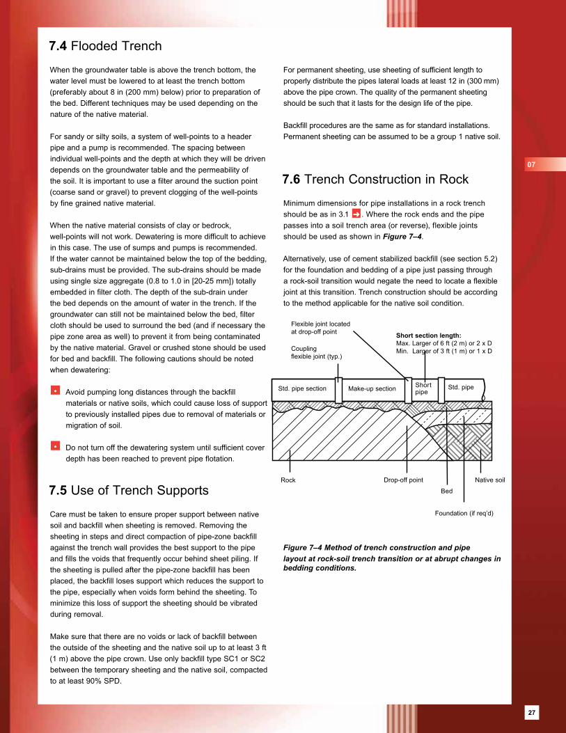
Minimum dimensions for pipe installations in a rock trench should be as in 3.1 ➜ . Where the rock ends and the pipe passes into a soil trench area (or reverse), flexible joints should be used as shown in Figure 7–4.
Alternatively, use of cement stabilized backfill (see section 5.2) for the foundation and bedding of a pipe just passing through a rock-soil transition would negate the need to locate a flexible joint at this transition. Trench construction should be according to the method applicable for the native soil condition.
Figure 7–4 Method of trench construction and pipe layout at rock-soil trench transition or at abrupt changes in bedding conditions.
Short section length:Max. Larger of 6 ft (2 m) or 2 x DMin. Larger of 3 ft (1 m) or 1 x D
Flexible joint locatedat drop-off point
Couplingflexible joint (typ.)
Drop-off pointRock
Bed
Foundation (if req’d)
Native soil
Std. pipe section Make-up section Short pipe
Std. pipe
For permanent sheeting, use sheeting of sufficient length to properly distribute the pipes lateral loads at least 12 in (300 mm) above the pipe crown. The quality of the permanent sheeting should be such that it lasts for the design life of the pipe.
Backfill procedures are the same as for standard installations. Permanent sheeting can be assumed to be a group 1 native soil.
07
27
28
7.7 Inadvertent Over-Excavation
Any inadvertent over-excavation of the trench walls or the trench bottom in the foundation, bed or pipe zone areas should be filled with backfill material compacted to a least 90% relative compaction.
7.8 Installation of Pipes on Slopes (Parallel)
General
• The angle at which slopes can become unstable depends on the quality of the soil. The risk of unstable conditions increases dramatically with slope angle.
• In general, pipes should not be installed on slopes greater then 15 degrees, or in areas where slope instability is suspected, unless supporting conditions have been verified by a proper geotechnical investigation.
Aboveground Installation
• The preferred method of installing pipes on steep slopes is above ground as above ground structures such as pipe supports are more easily defined, the quality of installation is easier to monitor and settlement easier to detect.
• See above ground installation brochure for more information ➜ .
Buried Installation
Before pipes are installed underground on slopes greater then 15 degrees, it is recommended that a geotechnical engineer be consulted. FLOWTITE pipes may be installed on slopes greater than 15 degrees provided the following minimum conditions are achieved:
• Long-term stability of the installation can be ensured with a proper geotechnical design.
• For slopes over 15 degrees, use either SC1 or cement-stabilized backfill in the pipe zone as backfill material.
• For slopes greater than 15 degrees, use one anchor rib at the center of each pipe section.
• Installation should always proceed from the low point and progress up the slope. Each pipe should be properly backfilled to grade before the next pipe is placed in the trench.
• The surface over the completed pipe trench must be protected against erosion from flowing water.
• Pipes are installed in straight alignment (plus or minus 0.2 degrees) with a minimum gap between pipe spigots.
• Absolute long-term movement of the backfill in the axial direction of the pipe must be less than 0.8 in (20 mm).
• The installation is properly drained to avoid washout of materials and ensure adequate soil shear strength.
• Stability of individual pipes is monitored throughout the construction phase and the first phases of operation. This can be done by controlling the gap between pipe spigots.
• A special pipe design may be required, consult the pipe supplier.
Perpendicular to the hillside
When pipes are installed perpendicular to the fall line of a steep slope, consultation with a geotechnical engineer is recommended when the slope angle exceeds 15 degrees to assure that the hillside remains stable.
The surface of the completed trench must be configured to eliminate depressions and preclude the formation of puddles water. The collection of water on a slope may reduce the stability of the slope.
07
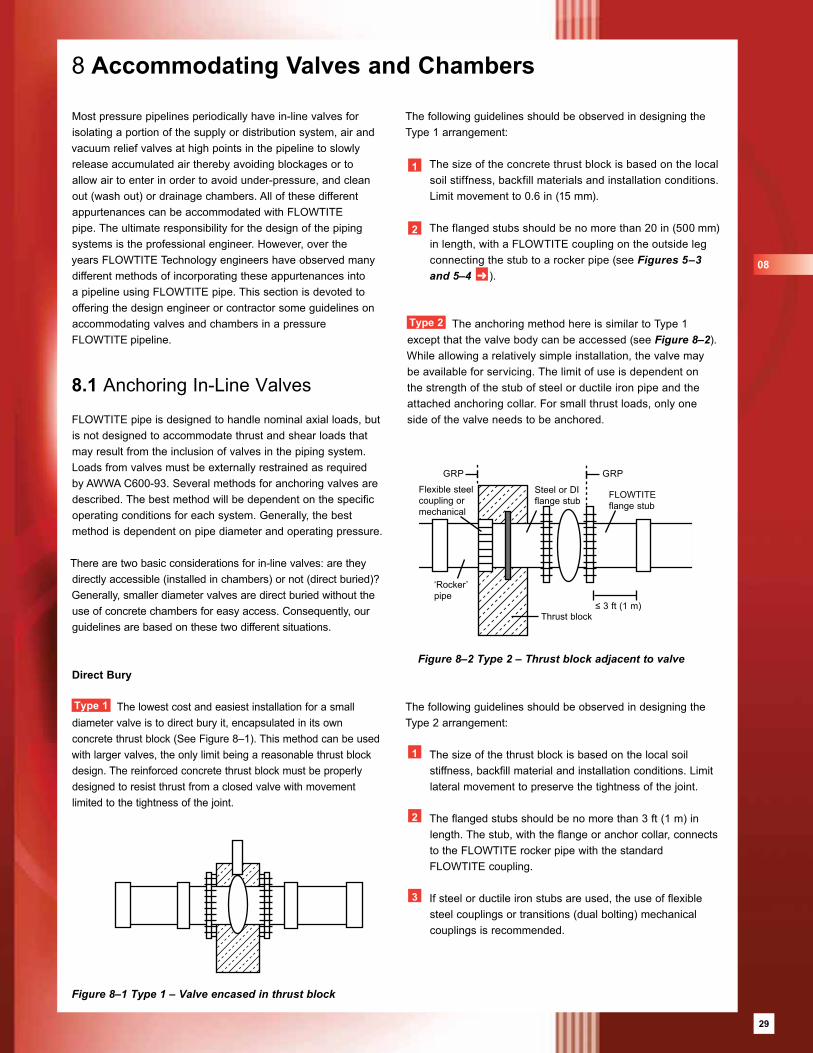
29
8 Accommodating Valves and Chambers
Most pressure pipelines periodically have in-line valves for isolating a portion of the supply or distribution system, air and vacuum relief valves at high points in the pipeline to slowly release accumulated air thereby avoiding blockages or to allow air to enter in order to avoid under-pressure, and clean out (wash out) or drainage chambers. All of these different appurtenances can be accommodated with FLOWTITE pipe. The ultimate responsibility for the design of the piping systems is the professional engineer. However, over the years FLOWTITE Technology engineers have observed many different methods of incorporating these appurtenances into a pipeline using FLOWTITE pipe. This section is devoted to offering the design engineer or contractor some guidelines on accommodating valves and chambers in a pressure FLOWTITE pipeline.
8.1 Anchoring In-Line Valves
FLOWTITE pipe is designed to handle nominal axial loads, but is not designed to accommodate thrust and shear loads that may result from the inclusion of valves in the piping system. Loads from valves must be externally restrained as required by AWWA C600-93. Several methods for anchoring valves are described. The best method will be dependent on the specific operating conditions for each system. Generally, the best method is dependent on pipe diameter and operating pressure.
There are two basic considerations for in-line valves: are they directly accessible (installed in chambers) or not (direct buried)? Generally, smaller diameter valves are direct buried without the use of concrete chambers for easy access. Consequently, our guidelines are based on these two different situations.
Direct Bury
Type 1 The lowest cost and easiest installation for a small diameter valve is to direct bury it, encapsulated in its own concrete thrust block (See Figure 8–1). This method can be used with larger valves, the only limit being a reasonable thrust block design. The reinforced concrete thrust block must be properly designed to resist thrust from a closed valve with movement limited to the tightness of the joint.
The following guidelines should be observed in designing the Type 1 arrangement:
1 The size of the concrete thrust block is based on the local soil stiffness, backfill materials and installation conditions. Limit movement to 0.6 in (15 mm).
2 The flanged stubs should be no more than 20 in (500 mm) in length, with a FLOWTITE coupling on the outside leg connecting the stub to a rocker pipe (see Figures 5–3 and 5–4 ➜ ).
Type 2 The anchoring method here is similar to Type 1 except that the valve body can be accessed (see Figure 8–2). While allowing a relatively simple installation, the valve may be available for servicing. The limit of use is dependent on the strength of the stub of steel or ductile iron pipe and the attached anchoring collar. For small thrust loads, only one side of the valve needs to be anchored.
The following guidelines should be observed in designing the Type 2 arrangement:
1 The size of the thrust block is based on the local soil stiffness, backfill material and installation conditions. Limit lateral movement to preserve the tightness of the joint.
2 The flanged stubs should be no more than 3 ft (1 m) in length. The stub, with the flange or anchor collar, connects to the FLOWTITE rocker pipe with the standard FLOWTITE coupling.
3 If steel or ductile iron stubs are used, the use of flexible steel couplings or transitions (dual bolting) mechanical couplings is recommended.
Figure 8–1 Type 1 – Valve encased in thrust block
Figure 8–2 Type 2 – Thrust block adjacent to valve
Flexible steelcoupling ormechanical
Steel or DIflange stub
FLOWTITEflange stub
‘Rocker’pipe
GRP GRP
≤ 3 ft (1 m)Thrust block
08
29
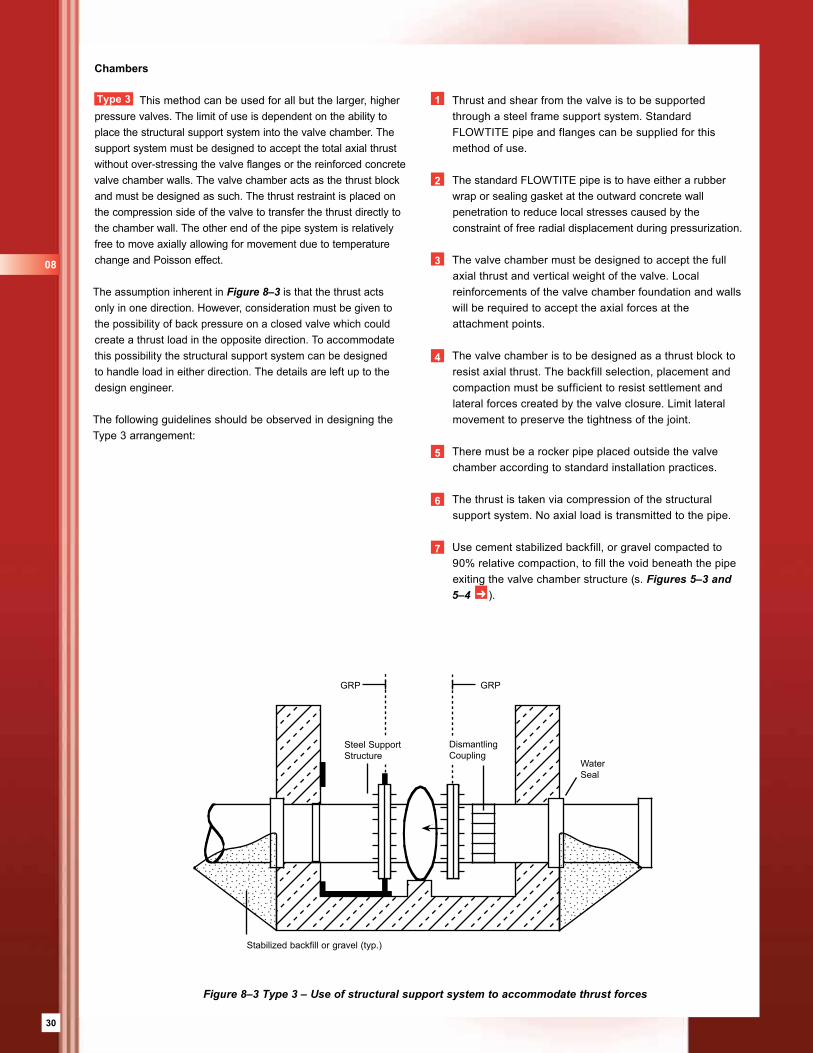
30
Chambers
Type 3 This method can be used for all but the larger, higher pressure valves. The limit of use is dependent on the ability to place the structural support system into the valve chamber. The support system must be designed to accept the total axial thrust without over-stressing the valve flanges or the reinforced concrete valve chamber walls. The valve chamber acts as the thrust block and must be designed as such. The thrust restraint is placed on the compression side of the valve to transfer the thrust directly to the chamber wall. The other end of the pipe system is relatively free to move axially allowing for movement due to temperature change and Poisson effect.
The assumption inherent in Figure 8–3 is that the thrust acts only in one direction. However, consideration must be given to the possibility of back pressure on a closed valve which could create a thrust load in the opposite direction. To accommodate this possibility the structural support system can be designed to handle load in either direction. The details are left up to the design engineer.
The following guidelines should be observed in designing the Type 3 arrangement:
1 Thrust and shear from the valve is to be supported through a steel frame support system. Standard FLOWTITE pipe and flanges can be supplied for this method of use.
2 The standard FLOWTITE pipe is to have either a rubber wrap or sealing gasket at the outward concrete wall penetration to reduce local stresses caused by the constraint of free radial displacement during pressurization.
3 The valve chamber must be designed to accept the full axial thrust and vertical weight of the valve. Local reinforcements of the valve chamber foundation and walls will be required to accept the axial forces at the attachment points.
4 The valve chamber is to be designed as a thrust block to resist axial thrust. The backfill selection, placement and compaction must be sufficient to resist settlement and lateral forces created by the valve closure. Limit lateral movement to preserve the tightness of the joint.
5 There must be a rocker pipe placed outside the valve chamber according to standard installation practices.
6 The thrust is taken via compression of the structural support system. No axial load is transmitted to the pipe.
7 Use cement stabilized backfill, or gravel compacted to 90% relative compaction, to fill the void beneath the pipe exiting the valve chamber structure (s. Figures 5–3 and 5–4 ➜ ).
Figure 8–3 Type 3 – Use of structural support system to accommodate thrust forces
Steel SupportStructure
DismantlingCoupling
WaterSeal
Stabilized backfill or gravel (typ.)
GRP GRP
08
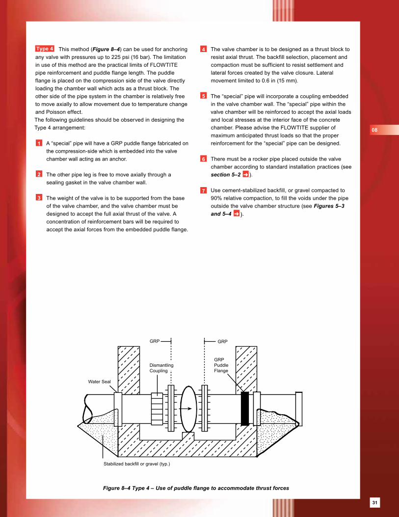
31
Type 4 This method (Figure 8–4) can be used for anchoring any valve with pressures up to 225 psi (16 bar). The limitation in use of this method are the practical limits of FLOWTITE pipe reinforcement and puddle flange length. The puddle flange is placed on the compression side of the valve directly loading the chamber wall which acts as a thrust block. The other side of the pipe system in the chamber is relatively free to move axially to allow movement due to temperature change and Poisson effect.The following guidelines should be observed in designing the Type 4 arrangement:
1 A “special” pipe will have a GRP puddle flange fabricated on the compression-side which is embedded into the valve chamber wall acting as an anchor.
2 The other pipe leg is free to move axially through a sealing gasket in the valve chamber wall.
3 The weight of the valve is to be supported from the base of the valve chamber, and the valve chamber must be designed to accept the full axial thrust of the valve. A concentration of reinforcement bars will be required to accept the axial forces from the embedded puddle flange.
Figure 8–4 Type 4 – Use of puddle flange to accommodate thrust forces
DismantlingCoupling
GRPPuddleFlange
Water Seal
Stabilized backfill or gravel (typ.)
GRP GRP
4 The valve chamber is to be designed as a thrust block to resist axial thrust. The backfill selection, placement and compaction must be sufficient to resist settlement and lateral forces created by the valve closure. Lateral movement limited to 0.6 in (15 mm).
5 The “special” pipe will incorporate a coupling embedded in the valve chamber wall. The “special” pipe within the valve chamber will be reinforced to accept the axial loads and local stresses at the interior face of the concrete chamber. Please advise the FLOWTITE supplier of maximum anticipated thrust loads so that the proper reinforcement for the “special” pipe can be designed.
6 There must be a rocker pipe placed outside the valve chamber according to standard installation practices (see section 5–2 ➜ ).
7 Use cement-stabilized backfill, or gravel compacted to 90% relative compaction, to fill the voids under the pipe outside the valve chamber structure (see Figures 5–3 and 5–4 ➜ ).
08
31
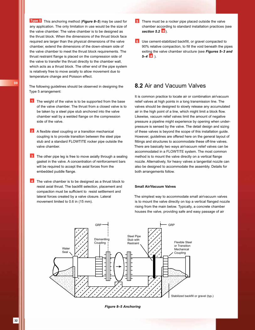
32
Type 5 This anchoring method (Figure 8–5) may be used for any application. The only limitation in use would be the size of the valve chamber. The valve chamber is to be designed as the thrust block. When the dimensions of the thrust block face required are larger than the physical dimensions of the valve chamber, extend the dimensions of the down-stream side of the valve chamber to meet the thrust block requirements. The thrust restraint flange is placed on the compression side of the valve to transfer the thrust directly to the chamber wall, which acts as a thrust block. The other end of the pipe system is relatively free to move axially to allow movement due to temperature change and Poisson effect.
The following guidelines should be observed in designing the Type 5 arrangement:
1 The weight of the valve is to be supported from the base of the valve chamber. The thrust from a closed valve is to be taken by a steel pipe stub anchored into the valve chamber wall by a welded flange on the compression side of the valve.
2 A flexible steel coupling or a transition mechanical coupling is to provide transition between the steel pipe stub and a standard FLOWTITE rocker pipe outside the valve chamber.
3 The other pipe leg is free to move axially through a sealing gasket in the valve. A concentration of reinforcement bars will be required to accept the axial forces from the embedded puddle flange.
4 The valve chamber is to be designed as a thrust block to resist axial thrust. The backfill selection, placement and compaction must be sufficient to resist settlement and lateral forces created by a valve closure. Lateral movement limited to 0.6 in (15 mm).
8.2 Air and Vacuum Valves
It is common practice to locate air or combination air/vacuum relief valves at high points in a long transmission line. The valves should be designed to slowly release any accumulated air in the high point of a line, which might limit a block flow. Likewise, vacuum relief valves limit the amount of negative pressure a pipeline might experience by opening when under-pressure is sensed by the valve. The detail design and sizing of these valves is beyond the scope of this installation guide. However, guidelines are offered here on the general layout of fittings and structures to accommodate these off-line valves. There are basically two ways air/vacuum relief valves can be accommodated in a FLOWTITE system. The most common method is to mount the valve directly on a vertical flange nozzle. Alternatively, for heavy valves a tangential nozzle can also be designed to accommodate the assembly. Details for both arrangements follow.
Small Air/Vacuum Valves
The simplest way to accommodate small air/vacuum valves is to mount the valve directly on top a vertical flanged nozzle rising from the main below. Typically, a concrete chamber houses the valve, providing safe and easy passage of air
5 There must be a rocker pipe placed outside the valve chamber according to standard installation practices (see section 5.2 ➜ ).
6 Use cement-stabilized backfill, or gravel compacted to 90% relative compaction, to fill the void beneath the pipes exiting the valve chamber structure (see Figures 5–3 and 5–4 ➜ ).
Figure 8–5 Anchoring
Steel PipeStub withRestraint Flexible Steel
or TransitionMechanicalCoupling
WaterSeal
Stabilized backfill or gravel (typ.)
GRP GRP
DismantlingCoupling
08
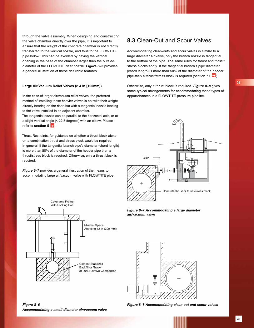
33
Figure 8–6 Accommodating a small diameter air/vacuum valve
Figure 8–7 Accommodating a large diameter air/vacuum valve
8.3 Clean-Out and Scour Valves
Accommodating clean-outs and scour valves is similar to a large diameter air valve, only the branch nozzle is tangential to the bottom of the pipe. The same rules for thrust and thrust/stress blocks apply. If the tangential branch’s pipe diameter (chord length) is more than 50% of the diameter of the header pipe then a thrust/stress block is required (section 7.1 ➜ ).
Otherwise, only a thrust block is required. Figure 8–8 gives some typical arrangements for accommodating these types of appurtenances in a FLOWTITE pressure pipeline.
Figure 8–8 Accommodating clean out and scour valves
through the valve assembly. When designing and constructing the valve chamber directly over the pipe, it is important to ensure that the weight of the concrete chamber is not directly transferred to the vertical nozzle, and thus to the FLOWTITE pipe below. This can be avoided by having the vertical opening in the base of the chamber larger than the outside diameter of the FLOWTITE riser nozzle. Figure 8–6 provides a general illustration of these desirable features.
Large Air/Vacuum Relief Valves (> 4 in [100mm])
In the case of larger air/vacuum relief valves, the preferred method of installing these heavier valves is not with their weight directly bearing on the riser, but with a tangential nozzle leading to the valve installed in an adjacent chamber. The tangential nozzle can be parallel to the horizontal axis, or at a slight vertical angle (< 22.5 degrees) with an elbow. Please refer to section 5 ➜ .
Thrust Restraints, for guidance on whether a thrust block alone or a combination thrust and stress block would be required.In general, if the tangential branch pipe’s diameter (chord length) is more than 50% of the diameter of the header pipe then a thrust/stress block is required. Otherwise, only a thrust block is required.
Figure 8–7 provides a general illustration of the means to accommodating large air/vacuum valve with FLOWTITE pipe.
Cement-Stabilized Backfill or Gravel at 90% Relative Compaction
Minimal SpaceAbove to 12 in (300 mm)
Cover and FrameWith Locking Bar
150 200
505
300
150
150
GRP
Concrete thrust or thrust/stress block
08
33
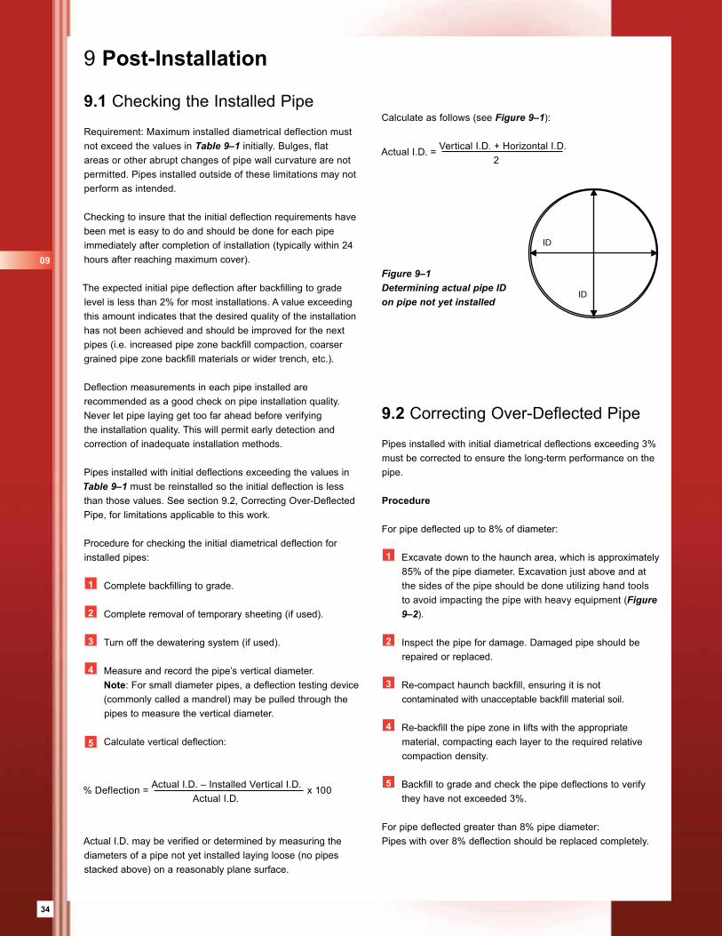
34
9 Post-Installation
9.1 Checking the Installed Pipe
Requirement: Maximum installed diametrical deflection must not exceed the values in Table 9–1 initially. Bulges, flat areas or other abrupt changes of pipe wall curvature are not permitted. Pipes installed outside of these limitations may not perform as intended.
Checking to insure that the initial deflection requirements have been met is easy to do and should be done for each pipe immediately after completion of installation (typically within 24 hours after reaching maximum cover).
The expected initial pipe deflection after backfilling to grade level is less than 2% for most installations. A value exceeding this amount indicates that the desired quality of the installation has not been achieved and should be improved for the next pipes (i.e. increased pipe zone backfill compaction, coarser grained pipe zone backfill materials or wider trench, etc.).
Deflection measurements in each pipe installed are recommended as a good check on pipe installation quality. Never let pipe laying get too far ahead before verifying the installation quality. This will permit early detection and correction of inadequate installation methods.
Pipes installed with initial deflections exceeding the values in Table 9–1 must be reinstalled so the initial deflection is less than those values. See section 9.2, Correcting Over-Deflected Pipe, for limitations applicable to this work.
Procedure for checking the initial diametrical deflection for installed pipes:
1 Complete backfilling to grade.
2 Complete removal of temporary sheeting (if used).
3 Turn off the dewatering system (if used).
4 Measure and record the pipe’s vertical diameter. Note: For small diameter pipes, a deflection testing device
(commonly called a mandrel) may be pulled through the pipes to measure the vertical diameter.
5 Calculate vertical deflection:
% Deflection = Actual I.D. – Installed Vertical I.D. x 100 Actual I.D.
Actual I.D. may be verified or determined by measuring the diameters of a pipe not yet installed laying loose (no pipes stacked above) on a reasonably plane surface.
9.2 Correcting Over-Deflected Pipe
Pipes installed with initial diametrical deflections exceeding 3% must be corrected to ensure the long-term performance on the pipe.
Procedure
For pipe deflected up to 8% of diameter:
1 Excavate down to the haunch area, which is approximately 85% of the pipe diameter. Excavation just above and at the sides of the pipe should be done utilizing hand tools to avoid impacting the pipe with heavy equipment (Figure 9–2).
2 Inspect the pipe for damage. Damaged pipe should be repaired or replaced.
3 Re-compact haunch backfill, ensuring it is not contaminated with unacceptable backfill material soil.
4 Re-backfill the pipe zone in lifts with the appropriate material, compacting each layer to the required relative compaction density.
5 Backfill to grade and check the pipe deflections to verify they have not exceeded 3%.
For pipe deflected greater than 8% pipe diameter: Pipes with over 8% deflection should be replaced completely.
Figure 9–1 Determining actual pipe ID on pipe not yet installed
Calculate as follows (see Figure 9–1):
Actual I.D. = Vertical I.D. + Horizontal I.D. 2
ID
ID
09
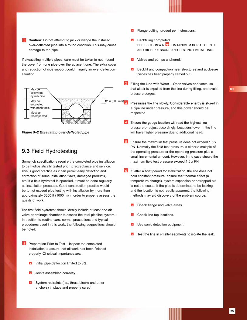
35
9.3 Field Hydrotesting
Some job specifications require the completed pipe installation to be hydrostatically tested prior to acceptance and service. This is good practice as it can permit early detection and correction of some installation flaws, damaged products, etc. If a field hydrotest is specified, it must be done regularly as installation proceeds. Good construction practice would be to not exceed pipe testing with installation by more than approximately 3300 ft (1000 m) in order to properly assess the quality of work.
The first field hydrotest should ideally include at least one air valve or drainage chamber to assess the total pipeline system. In addition to routine care, normal precautions and typical procedures used in this work, the following suggestions should be noted:
1 Preparation Prior to Test – Inspect the completed installation to assure that all work has been finished properly. Of critical importance are:
• Initial pipe deflection limited to 3% • Joints assembled correctly. • System restraints (i.e., thrust blocks and other
anchors) in place and properly cured.
• Flange bolting torqued per instructions.
• Backfilling completed. see section a.6 ➜ on minimum burial depth
and high pressure and testing limitations.
• Valves and pumps anchored. • Backfill and compaction near structures and at closure
pieces has been properly carried out.
2 Filling the Line with Water – Open valves and vents, so that all air is expelled from the line during filling, and avoid pressure surges.
3 Pressurize the line slowly. Considerable energy is stored in a pipeline under pressure, and this power should be respected.
4 Ensure the gauge location will read the highest line pressure or adjust accordingly. Locations lower in the line will have higher pressure due to additional head.
5 Ensure the maximum test pressure does not exceed 1.5 x PN. Normally the field test pressure is either a multiple of the operating pressure or the operating pressure plus a small incremental amount. However, in no case should the maximum field test pressure exceed 1.5 x PN.
6 If, after a brief period for stabilization, the line does not hold constant pressure, ensure that thermal effect (a temperature change), system expansion or entrapped air is not the cause. If the pipe is determined to be leaking and the location is not readily apparent, the following methods may aid discovery of the problem source:
• Check flange and valve areas. • Check line tap locations. • Use sonic detection equipment. • Test the line in smaller segments to isolate the leak.
! Caution: Do not attempt to jack or wedge the installed over-deflected pipe into a round condition. This may cause damage to the pipe.
If excavating multiple pipes, care must be taken to not mound the cover from one pipe over the adjacent one. The extra cover and reduction of side support could magnify an over-deflection situation.
Figure 9–2 Excavating over-deflected pipe
May beexcavated by machine
May beexcavated with hand tools
Must be recompacted
12 in (300 mm)
09
35
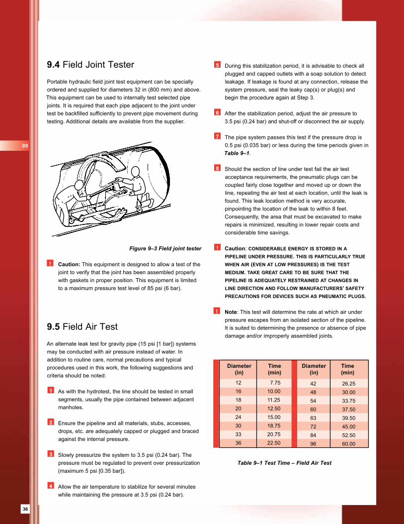
36
9.5 Field Air Test
An alternate leak test for gravity pipe (15 psi [1 bar]) systems may be conducted with air pressure instead of water. In addition to routine care, normal precautions and typical procedures used in this work, the following suggestions and criteria should be noted:
1 As with the hydrotest, the line should be tested in small segments, usually the pipe contained between adjacent manholes.
2 Ensure the pipeline and all materials, stubs, accesses, drops, etc. are adequately capped or plugged and braced against the internal pressure.
3 Slowly pressurize the system to 3.5 psi (0.24 bar). The pressure must be regulated to prevent over pressurization (maximum 5 psi [0.35 bar]).
4 Allow the air temperature to stabilize for several minutes while maintaining the pressure at 3.5 psi (0.24 bar).
Table 9–1 Test Time – Field Air Test
9.4 Field Joint Tester
Portable hydraulic field joint test equipment can be specially ordered and supplied for diameters 32 in (800 mm) and above.This equipment can be used to internally test selected pipe joints. It is required that each pipe adjacent to the joint under test be backfilled sufficiently to prevent pipe movement during testing. Additional details are available from the supplier.
! Caution: This equipment is designed to allow a test of the joint to verify that the joint has been assembled properly with gaskets in proper position. This equipment is limited to a maximum pressure test level of 85 psi (6 bar).
5 During this stabilization period, it is advisable to check all plugged and capped outlets with a soap solution to detect leakage. If leakage is found at any connection, release the system pressure, seal the leaky cap(s) or plug(s) and begin the procedure again at Step 3.
6 After the stabilization period, adjust the air pressure to 3.5 psi (0.24 bar) and shut-off or disconnect the air supply.
7 The pipe system passes this test if the pressure drop is 0.5 psi (0.035 bar) or less during the time periods given in Table 9–1.
8 Should the section of line under test fail the air test acceptance requirements, the pneumatic plugs can be coupled fairly close together and moved up or down the line, repeating the air test at each location, until the leak is found. This leak location method is very accurate, pinpointing the location of the leak to within 8 feet. Consequently, the area that must be excavated to make repairs is minimized, resulting in lower repair costs and considerable time savings.
! Caution: considerable energy is stored in a pipeline under pressure. this is particu larly true when air (even at low pressures) is the test medium. take great care to be sure that the pipeline is adequately restrained at changes in line direction and follow manufacturers’ safety precautions for devices such as pneumatic plugs.
! Note: This test will determine the rate at which air under pressure escapes from an isolated section of the pipeline. It is suited to determining the presence or absence of pipe damage and/or improperly assembled joints.
Figure 9–3 Field joint tester
Table 9–1 Allowable Vertical Deflection.
42 26.2548 30.0054 33.7560 37.5063 39.5072 45.0084 52.5096 60.00
Diameter Time Diameter Time (in) (min) (in) (min)
12 7.7516 10.0018 11.2520 12.5024 15.0030 18.7533 20.7536 22.50
09
37
10 Alternate InstallationsIf the burial depth requirements for the selected pipe stiffness, installation type and native soil group exceeds feasible compaction limits alternative installation procedures must be considered.
Three alternative installation methods are available:
• Wider Trench
• Permanent Sheeting (see section 7.5 ➜ )
• Stabilized Backfill (Cement)
10.1 Wide Trench
Increasing the trench width distances the poor native soil farther from the pipe allowing a deeper installation and higher allowable negative pressure (vacuum).
10.2 Cement-Stabilized Backfill
Scope
Cement is mixed with moist sandy soil, and the mixture placed and compacted as a typical backfill soil. The amount of Type 3 Portland cement added to the sandy soil is approximately 4 to 5 parts per hundred weight of the soil. The moisture level should be in the range of 5 to 10%.
The compaction density required is dependent on the cover depth prior to allowing the stabilized backfill to set. If the desired cover depth is small, the required density is low. The cement-stabilized backfill can set in one or two days and the cover fill can be placed to grade, with a maximum total cover depth of 16 ft (5 m).
Mixture
100 parts soil (dry weight), 4 to 5 parts Type 3 Portland cement, and 12% water (+/-6%). Account for the natural moisture content of the soil when adding water. The soil can be type SC2 or SC3. Type SC2 soil is the easiest to mix; however, SC3 may be used. Mixing can be accomplished on the ground by spreading a layer of backfill soil and a thin layer of cement over it, and then mixing the two together.
The mixing can be done by hand, with a hoe, or mechanically with any appropriate device. The backfill should be placed within two hours of mixing.
Compaction
The cement-stabilized backfill will achieve a high stiffness without the need for significant compaction. Be sure to place backfill under the pipe haunches and compact with a haunch-compaction tool. A soil compactor is required to compact the cement-stabilized backfill next to the pipe. One pass of the compactor with 12 in (300 mm) lifts is sufficient for most conditions in which the cover depth is less than 6 ft (2 m).
Check the pipe deflection to ensure the compaction is adequate to support the pipe. If initial deflection exceeds 2.5%, increase the amount of compaction or use less cover until the cement-stabilized backfill sets in one or two days.
If a significant depth of cover is to be placed before the cement-stabilized backfill is allowed to set, a higher level of compaction is required to prevent excessive pipe deflection. Keep the initial deflection to no more than 2.5%. The amount of compaction effort required is dependent on cover depth, lift height and specific soil used in the mixture.
It is also recommended that a stabilized backfill be used in the immediate vicinity of large thrust blocks, or valve chambers and in areas of significant over-excavation.
10
37

38
Notes
39
Appendix A Installation Design .......................................................................................................40 A.1 Design Principles .....................................................................................................40 A.2 Native Soil Stiffness Groups ....................................................................................42 A.3 Backfill Constrained Modulus, Msb ...........................................................................42 A.4 Trench Width ............................................................................................................44 A.5 Negative Pressure ...................................................................................................44 A.6 Burial Limitation – Minimum .....................................................................................45 A.7 Seismic Loading .......................................................................................................45 A.8 Backfill Migration ......................................................................................................46Appendix B Installation Tables .......................................................................................................46Appendix C Classification and Properties of Native Soils ..............................................................60Appendix D Classification and Properties of Backfill Soils .............................................................61Appendix E Field Testing to assist Classification of Native Soils ..................................................63Appendix F Compaction of Backfill ................................................................................................63Appendix G Definitions and Terminology .......................................................................................65Appendix H Approximate Weights for Pipe and Couplings ............................................................66Appendix I Joint Lubricant Requirements .....................................................................................67Appendix J Cleaning of FLOWTITE Sewer Pipe ...........................................................................67
Appendix AWWA M 45
app.
39
40
Appendix
Appendix A – Installation Design
The long life and good performance of FLOWTITE pipe is ensured by proper handling and installation. FLOWTITE pipe is flexible and allows the designer to utilize the bedding and pipe zone backfill for support. Together the pipe and embedment material form a “pipe-soil system” that provides proven long-term performance.
This Appendix is based on the current AWWA approach.
A.1 Design Principles
A flexible pipe like FLOWTITE will deflect when subjected to soil and traffic loads. When deflected, the increase of the pipe horizontal diameter will develop passive soil resistance counteracting the deflection.
The amount of deflection needed to generate sufficient earth pressure to resist any given load will primarily depend on the stiffness of the backfill material and native soil as well as trench width. The initial deflection of the pipe measured after backfilling to level can, therefore, be considered as a direct indicator of the quality of the pipe installation.
Settlement and consolidation of the soil surrounding the pipe will result in an increase of the pipe deflection over time. Almost all of the increase in deflection will take place during the first 1 to 2 years after installation. Afterwards, the deflection will stabilize.
The initial deflections must not exceed 3% of diameter. Pipes installed outside this limit may not perform as intended.The type of installation appropriate for FLOWTITE pipe varies with native soil characteristics, cover depth, loading conditions and available backfill materials. The native soil and backfill material must adequately confine the pipe to achieve proper pipe support.
The support of the surrounding soil is defined in terms of the constrained or one dimensional soil modulus, Ms, at pipe elevation. To determine Ms for a buried pipe, separate Ms values for native soil, Msn, and the pipe backfill surround, Msb, must be determined and, then, combined depending on the trench width.
The most important installation design parameters are indicated in Figure A–1. The native soil stiffness, burial depth, groundwater level, life load and internal vacuum must be determined according to the conditions along the route of the planned pipe installation. Based upon this information and available backfill material, backfill compaction, trench width and pipe stiffness is selected.
Ground level
Groundwater level
Pipe stiffness
Internal vacuum
app.
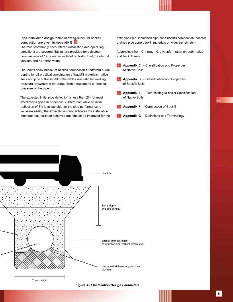
41
Ground level
Groundwater level
Pipe stiffness
Internal vacuum
Figure A–1 Installation Design Parameters
Pipe installation design tables showing minimum backfill compaction are given in Appendix B ➜ . The most commonly encountered installation and operating conditions are covered. Tables are provided for selected combinations of 1) groundwater level, 2) traffic load, 3) internal vacuum and 4) trench width.
The tables show minimum backfill compaction at different burial depths for all practical combination of backfill materials, native soils and pipe stiffness. All of the tables are valid for working pressure anywhere in the range from atmospheric to nominal pressure of the pipe.
The expected initial pipe deflection is less than 2% for most installations given in Appendix B. Therefore, while an initial deflection of 3% is acceptable for the pipe performance, a value exceeding the expected amount indicates the installation intended has not been achieved and should be improved for the
next pipes (i.e. increased pipe zone backfill compaction, coarser grained pipe zone backfill materials or wider trench, etc.).
Appendices from C through G give information on both native and backfill soils.
• Appendix C – Classification and Properties of Native Soils
• Appendix D – Classification and Properties of Backfill Soils
• Appendix E – Field Testing to assist Classification of Native Soils
• Appendix F – Compaction of Backfill
• Appendix G – Definitions and Terminology
Live load
Burial depth and soil density
Backfill stiffness class,compaction and vertical stress level
Native soil stiffness at pipe zone elevation
Trench width
app.
41
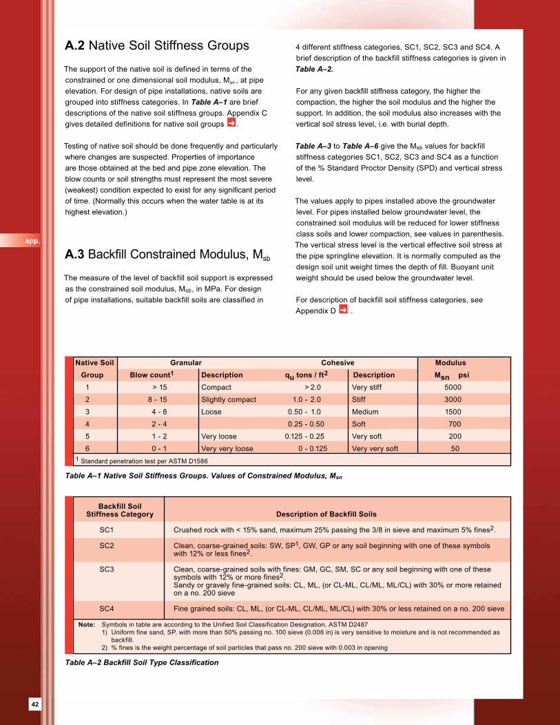
42
A.2 Native Soil Stiffness Groups
The support of the native soil is defined in terms of the constrained or one dimensional soil modulus, Msn , at pipe elevation. For design of pipe installations, native soils are grouped into stiffness categories. In Table A–1 are brief descriptions of the native soil stiffness groups. Appendix C gives detailed definitions for native soil groups ➜ .
Testing of native soil should be done frequently and particularly where changes are suspected. Properties of importance are those obtained at the bed and pipe zone elevation. The blow counts or soil strengths must represent the most severe (weakest) condition expected to exist for any significant period of time. (Normally this occurs when the water table is at its highest elevation.)
A.3 Backfill Constrained Modulus, Msb
The measure of the level of backfill soil support is expressed as the constrained soil modulus, Msb, in MPa. For design of pipe installations, suitable backfill soils are classified in
Backfill Soil Stiffness Category Description of Backfill Soils
SC1 Crushed rock with < 15% sand, maximum 25% passing the 3/8 in sieve and maximum 5% fines2.
SC2 Clean, coarse-grained soils: SW, SP1, GW, GP or any soil beginning with one of these symbols with 12% or less fines2.
SC3 Clean, coarse-grained soils with fines: GM, GC, SM, SC or any soil beginning with one of these symbols with 12% or more fines2. Sandy or gravely fine-grained soils: CL, ML, (or CL-ML, CL/ML, ML/CL) with 30% or more retained on a no. 200 sieve
SC4 Fine grained soils: CL, ML, (or CL-ML, CL/ML, ML/CL) with 30% or less retained on a no. 200 sieve
Note: Symbols in table are according to the Unified Soil Classification Designation, ASTM D2487 1) Uniform fine sand, SP, with more than 50% passing no. 100 sieve (0.006 in) is very sensitive to moisture and is not recommended as backfill. 2) % fines is the weight percentage of soil particles that pass no. 200 sieve with 0.003 in opening
Table A–2 Backfill Soil Type Classification
Table A–1 Native Soil Stiffness Groups. Values of Constrained Modulus, Msn
Native Soil Granular Cohesive Modulus Group Blow count1 Description qu tons / ft2 Description Msn psi 1 > 15 Compact > 2.0 Very stiff 5000
2 8 - 15 Slightly compact 1.0 - 2.0 Stiff 3000
3 4 - 8 Loose 0.50 - 1.0 Medium 1500
4 2 - 4 0.25 - 0.50 Soft 700
5 1 - 2 Very loose 0.125 - 0.25 Very soft 200
6 0 - 1 Very very loose 0 - 0.125 Very very soft 501 Standard penetration test per ASTM D1586
4 different stiffness categories, SC1, SC2, SC3 and SC4. A brief description of the backfill stiffness categories is given in Table A–2.
For any given backfill stiffness category, the higher the compaction, the higher the soil modulus and the higher the support. In addition, the soil modulus also increases with the vertical soil stress level, i.e. with burial depth.
Table A–3 to Table A–6 give the Msb values for backfill stiffness categories SC1, SC2, SC3 and SC4 as a function of the % Standard Proctor Density (SPD) and vertical stress level.
The values apply to pipes installed above the groundwater level. For pipes installed below groundwater level, the constrained soil modulus will be reduced for lower stiffness class soils and lower compaction, see values in parenthesis. The vertical stress level is the vertical effective soil stress at the pipe springline elevation. It is normally computed as the design soil unit weight times the depth of fill. Buoyant unit weight should be used below the groundwater level.
For description of backfill soil stiffness categories, see Appendix D ➜ .
app.
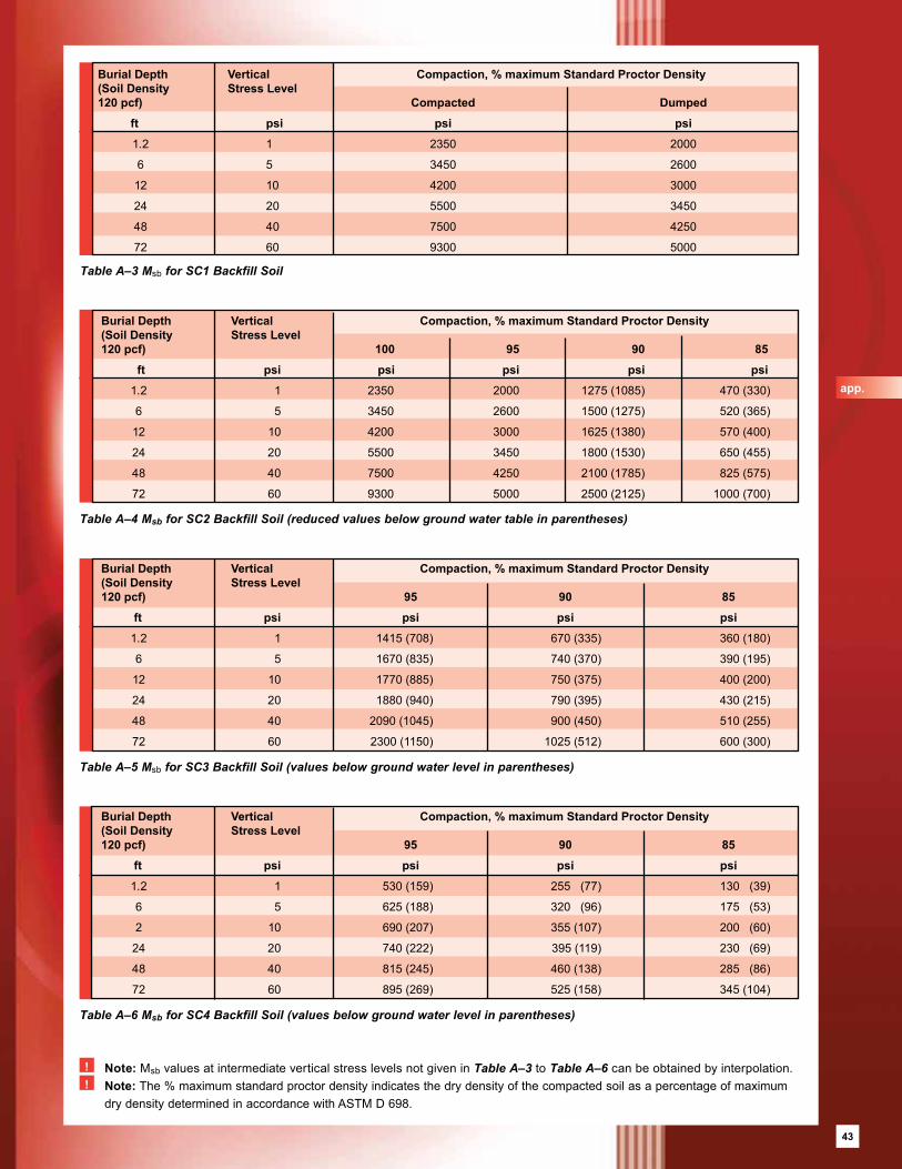
43
! Note: Msb values at intermediate vertical stress levels not given in Table A–3 to Table A–6 can be obtained by interpolation.! Note: The % maximum standard proctor density indicates the dry density of the compacted soil as a percentage of maximum
dry density determined in accordance with ASTM D 698.
Table A–3 Msb for SC1 Backfill Soil
Table A–4 Msb for SC2 Backfill Soil (reduced values below ground water table in parentheses)
Table A–6 Msb for SC4 Backfill Soil (values below ground water level in parentheses)
Table A–5 Msb for SC3 Backfill Soil (values below ground water level in parentheses)
Burial Depth Vertical Compaction, % maximum Standard Proctor Density(Soil Density Stress Level 120 pcf) 100 95 90 85
ft psi psi psi psi psi
1.2 1 2350 2000 1275 (1085) 470 (330)
6 5 3450 2600 1500 (1275) 520 (365)
12 10 4200 3000 1625 (1380) 570 (400)
24 20 5500 3450 1800 (1530) 650 (455)
48 40 7500 4250 2100 (1785) 825 (575)
72 60 9300 5000 2500 (2125) 1000 (700)
Burial Depth Vertical Compaction, % maximum Standard Proctor Density(Soil Density Stress Level 120 pcf) 95 90 85
ft psi psi psi psi
1.2 1 1415 (708) 670 (335) 360 (180)
6 5 1670 (835) 740 (370) 390 (195)
12 10 1770 (885) 750 (375) 400 (200)
24 20 1880 (940) 790 (395) 430 (215)
48 40 2090 (1045) 900 (450) 510 (255)
72 60 2300 (1150) 1025 (512) 600 (300)
Burial Depth Vertical Compaction, % maximum Standard Proctor Density(Soil Density Stress Level 120 pcf) 95 90 85
ft psi psi psi psi
1.2 1 530 (159) 255 (77) 130 (39)
6 5 625 (188) 320 (96) 175 (53)
2 10 690 (207) 355 (107) 200 (60)
24 20 740 (222) 395 (119) 230 (69)
48 40 815 (245) 460 (138) 285 (86)
72 60 895 (269) 525 (158) 345 (104)
Burial Depth Vertical Compaction, % maximum Standard Proctor Density(Soil Density Stress Level 120 pcf) Compacted Dumped
ft psi psi psi
1.2 1 2350 2000
6 5 3450 2600
12 10 4200 3000
24 20 5500 3450
48 40 7500 4250
72 60 9300 5000
app.
43
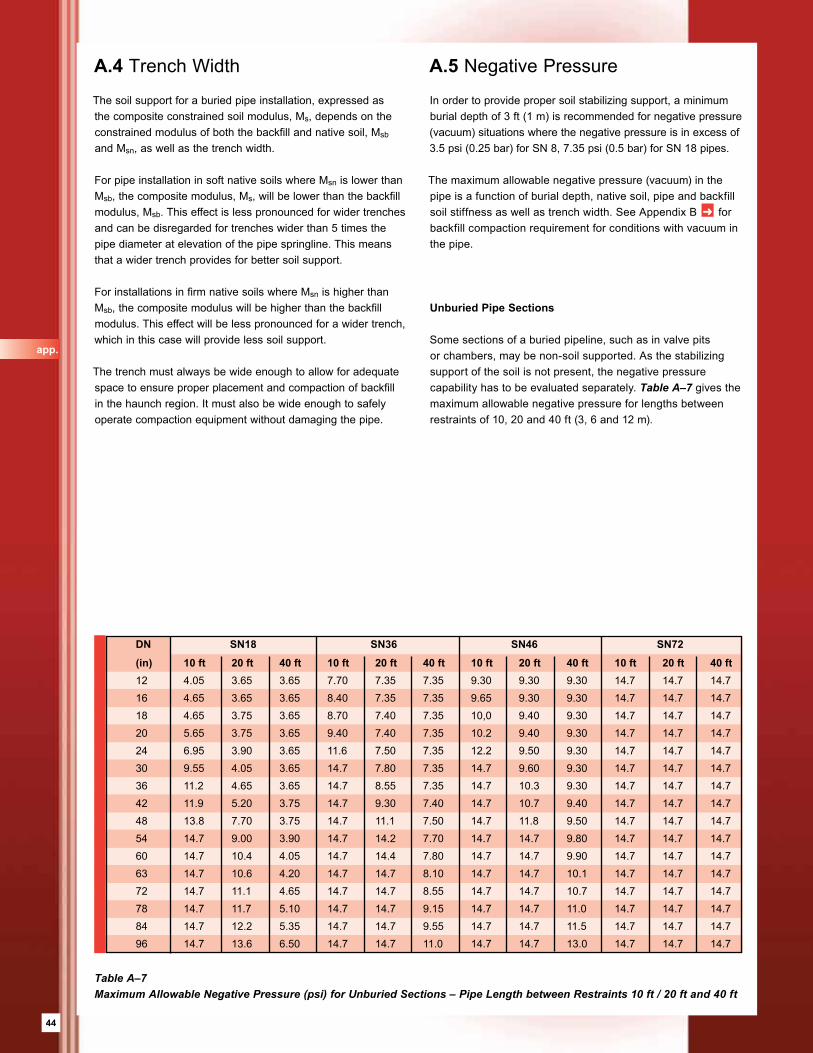
44
A.5 Negative Pressure
In order to provide proper soil stabilizing support, a minimum burial depth of 3 ft (1 m) is recommended for negative pressure (vacuum) situations where the negative pressure is in excess of 3.5 psi (0.25 bar) for SN 8, 7.35 psi (0.5 bar) for SN 18 pipes.
The maximum allowable negative pressure (vacuum) in the pipe is a function of burial depth, native soil, pipe and backfill soil stiffness as well as trench width. See Appendix B ➜ for backfill compaction requirement for conditions with vacuum in the pipe.
Unburied Pipe Sections
Some sections of a buried pipeline, such as in valve pits or chambers, may be non-soil supported. As the stabilizing support of the soil is not present, the negative pressure capability has to be evaluated separately. Table A–7 gives the maximum allowable negative pressure for lengths between restraints of 10, 20 and 40 ft (3, 6 and 12 m).
Table A–7 Maximum Allowable Negative Pressure (psi) for Unburied Sections – Pipe Length between Restraints 10 ft / 20 ft and 40 ft
A.4 Trench Width
The soil support for a buried pipe installation, expressed as the composite constrained soil modulus, Ms, depends on the constrained modulus of both the backfill and native soil, Msb and Msn, as well as the trench width.
For pipe installation in soft native soils where Msn is lower than Msb, the composite modulus, Ms, will be lower than the backfill modulus, Msb. This effect is less pronounced for wider trenches and can be disregarded for trenches wider than 5 times the pipe diameter at elevation of the pipe springline. This means that a wider trench provides for better soil support.
For installations in firm native soils where Msn is higher than Msb, the composite modulus will be higher than the backfill modulus. This effect will be less pronounced for a wider trench, which in this case will provide less soil support.
The trench must always be wide enough to allow for adequate space to ensure proper placement and compaction of backfill in the haunch region. It must also be wide enough to safely operate compaction equipment without damaging the pipe.
DN SN18 SN36 SN46 SN72
(in) 10 ft 20 ft 40 ft 10 ft 20 ft 40 ft 10 ft 20 ft 40 ft 10 ft 20 ft 40 ft12 4.05 3.65 3.65 7.70 7.35 7.35 9.30 9.30 9.30 14.7 14.7 14.716 4.65 3.65 3.65 8.40 7.35 7.35 9.65 9.30 9.30 14.7 14.7 14.718 4.65 3.75 3.65 8.70 7.40 7.35 10,0 9.40 9.30 14.7 14.7 14.720 5.65 3.75 3.65 9.40 7.40 7.35 10.2 9.40 9.30 14.7 14.7 14.724 6.95 3.90 3.65 11.6 7.50 7.35 12.2 9.50 9.30 14.7 14.7 14.730 9.55 4.05 3.65 14.7 7.80 7.35 14.7 9.60 9.30 14.7 14.7 14.736 11.2 4.65 3.65 14.7 8.55 7.35 14.7 10.3 9.30 14.7 14.7 14.742 11.9 5.20 3.75 14.7 9.30 7.40 14.7 10.7 9.40 14.7 14.7 14.748 13.8 7.70 3.75 14.7 11.1 7.50 14.7 11.8 9.50 14.7 14.7 14.754 14.7 9.00 3.90 14.7 14.2 7.70 14.7 14.7 9.80 14.7 14.7 14.760 14.7 10.4 4.05 14.7 14.4 7.80 14.7 14.7 9.90 14.7 14.7 14.763 14.7 10.6 4.20 14.7 14.7 8.10 14.7 14.7 10.1 14.7 14.7 14.772 14.7 11.1 4.65 14.7 14.7 8.55 14.7 14.7 10.7 14.7 14.7 14.778 14.7 11.7 5.10 14.7 14.7 9.15 14.7 14.7 11.0 14.7 14.7 14.784 14.7 12.2 5.35 14.7 14.7 9.55 14.7 14.7 11.5 14.7 14.7 14.796 14.7 13.6 6.50 14.7 14.7 11.0 14.7 14.7 13.0 14.7 14.7 14.7
app.
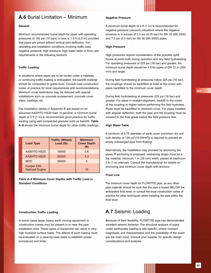
45
Negative Pressure
A minimum burial depth of 3 ft (1 m) is recommended for negative pressure (vacuum) situations where the negative pressure is in excess of 3.5 psi (0.25 bar) for SN 18 (SN 2500) and 7.5 psi (0.5 bar) for SN 36 (SN 5000) pipes.
High Pressure
High pressures require consideration of the possible uplift forces at joints both during operation and any field hydrotesting.For operating pressures of 225 psi (16 bar) and greater, the minimum burial depth should be 4 ft for pipes of DN 12 in (300 mm) and larger.
During field hydrotesting at pressures below 225 psi (16 bar), the couplings should be backfilled at least to the crown with pipes backfilled to the minimum cover depth.
During field hydrotesting at pressures 225 psi (16 bar) and greater: For pipes in straight alignment, backfill to the crown of the coupling or higher before performing the field hydrotest. Pipes must be backfilled to minimum cover. For pipes installed with angular deflection, both the pipe and the coupling must be covered to the final grade before the field pressure test.
High Water Table
A minimum of 0.75 diameter of earth cover (minimum dry soil bulk density of 120 pcf [19 kN/m3]) is required to prevent an empty submerged pipe from floating.
Alternatively, the installation may proceed by anchoring the pipes. If anchoring is proposed, restraining straps must be a flat material, minimum 1 in (25 mm) width, placed at maximum 3 ft (1 m) intervals. Consult the manufacturer for details on anchoring and minimum cover depth with anchors.
Frost Line
The minimum cover depth for FLOWTITE pipe, as any other pipe material, should be such that the pipe is buried BELOW the anticipated frost level, or consult the local construction codes of practice for other techniques when installing the pipe within the frost level.
A.7 Seismic Loading
Because of their flexibility, FLOWTITE pipe has demonstrated excellent seismic behavior. The structural analysis of pipes under earthquake loading is site specific, where moment magnitude, soil characteristics and the probability of the event are the main input. Consult your supplier for specific design considerations and analysis.
A.6 Burial Limitation – Minimum
General
Minimum recommended burial depth for pipes with operating pressures of 150 psi (10 bars) or less is 1.5 ft (0.5 m) provided that pipes are joined without vertical joint deflection. For operating and installation conditions involving traffic load, negative pressure, high pressure, high water table or frost, see requirements in the following sections.
Traffic Loading
In situations where pipes are to be buried under a roadway or continuing traffic loading is anticipated, the backfill material should be compacted to grade level. Consult road construction codes of practice for local requirements and recommendations. Minimum cover restrictions may be reduced with special installations such as concrete encasement, concrete cover slabs, castings, etc.
The installation tables in Appendix B are based on an assumed AASHTO HS20 load. In general, a minimum burial depth of 3 ft (1 m) is recommended good practice for traffic loading using well compacted granular soils as backfill. Table A–8 shows the minimum burial depth for other traffic loadings.
Construction Traffic Loading
In some cases large, heavy earth moving equipment or construction cranes may be present in or near the pipe installation area. These types of equipment can result in very high localized surface loads. The effects of such loading must be evaluated on a case-by-case basis to establish proper procedures and limits.
Table A–8 Minimum Cover Depths with Traffic Load in Standard Conditions
Traffic (Wheel) MinimumLoad Type Load (lb) Cover Depth (ft) AASHTO HS20 16000 2.6
AASHTO HS25 20000 3.3
MOC 36000 5
Cooper E80 Railroad Engine 10
app.
45
46
Appendix B – Installation Tables
Pipe installation design tables showing minimum backfill compaction are given in this Appendix. The minimum backfill compaction is given at different burial depths for all practical combinations of backfill stiffness category, native soil stiffness group and pipe stiffness. Both standard, Bd/D = 1.8 and wide, Bd/D = 3.0, trenches are covered. Tables are provided for selected combinations of 1) groundwater level, 2) traffic load and 3) internal vacuum. All of the tables are valid for working pressure anywhere in the range from atmospheric to nominal pressure of the pipe.
The minimum backfill compaction is expressed as percent standard proctor density for backfill soil categories SC2, SC3 and SC4. For crushed rock as backfill, SC1, the minimum compaction is expressed either as dumped, D, or compacted, C. Note that SC1 backfill material also has to be worked into the haunch zone for installation conditions where compaction is otherwise not required.
The compaction values recommended are to be considered as a minimum values and field densities should be at or higher than the requirement. Include considerations for seasonal variations when assessing the potential for moisture content of both in situ and backfill soils.
A.8 Backfill Migration
When open graded material is placed adjacent to a finer material, fines may migrate into the coarser material under the action of hydraulic gradient from groundwater flow. Significant hydraulic gradients may arise in the pipeline trench during construction, when water levels are controlled by pumping, or after construction, when permeable underdrain or embedment materials act as a drain under high ground water levels. Field experience shows that migration can result in significant loss of pipe support and increase of deflections.
The gradation and relative size of the embedment and adjacent materials must be compatible in order to minimize migration. In general, where significant groundwater flow is anticipated, avoid placing coarse, open-graded material, such as SC1, below or adjacent to finer material unless methods are employed to impede migration.
Consider the use of an appropriate soil filter or a geotextile filter fabric along the boundary of incompatible materials.The following filter gradation criteria may be used to restrict migration of fines into the voids of coarser material under hydraulic gradient:
• D15/d85 < 5 where D15 is the sieve opening size passing 15 percent by weight of the coarser material and d85 is the sieve opening size passing 85 percent by weight of the finer material.
• D50/d50 < 25 where D50 is the sieve opening size passing 50 percent by weight of the coarser material and d50 is the sieve opening size passing 50 percent by weight of the finer material. This criterion need not apply if the coarser material is well graded (see ASTM D 2487).
If the finer material is a medium to highly plastic clay (CL or CH), then the following criterion may be used in lieu of the D15/d85 criteria: D15 < 0.02 in (0.5 mm) where D15 is the sieve opening size passing 15 percent by weight of the coarser material.
The aforementioned criteria may need to be modified if one of the materials is gap graded. Materials selected for use based on filter gradation criteria should be handled and placed in a manner that will minimize segregation.
Where incompatible materials must be used, they must be separated by filter fabric designed to last the life of the pipeline to prevent wash-away and migration. The filter fabric must completely surround the bedding and pipe zone backfill material and must be folded over the pipe zone area in order to prevent contamination of the selected backfill material.
app.
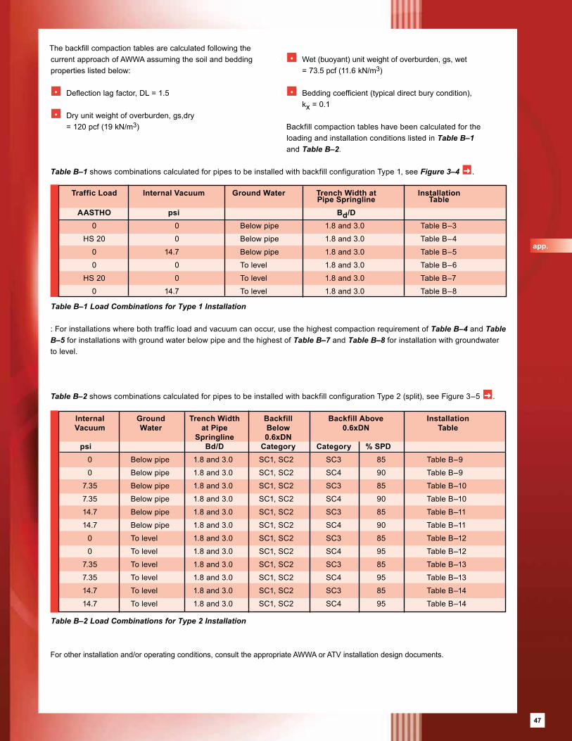
47
Table B–1 Load Combinations for Type 1 Installation
Traffic Load Internal Vacuum Ground Water Trench Width at Installation Pipe Springline Table AASTHO psi Bd/D 0 0 Below pipe 1.8 and 3.0 Table B–3
HS 20 0 Below pipe 1.8 and 3.0 Table B–4
0 14.7 Below pipe 1.8 and 3.0 Table B–5
0 0 To level 1.8 and 3.0 Table B–6
HS 20 0 To level 1.8 and 3.0 Table B–7
0 14.7 To level 1.8 and 3.0 Table B–8
For other installation and/or operating conditions, consult the appropriate AWWA or ATV installation design documents.
Table B–2 Load Combinations for Type 2 Installation
Internal Ground Trench Width Backfill Backfill Above Installation Vacuum Water at Pipe Below 0.6xDN Table Springline 0.6xDN psi Bd/D Category Category % SPD 0 Below pipe 1.8 and 3.0 SC1, SC2 SC3 85 Table B–9
0 Below pipe 1.8 and 3.0 SC1, SC2 SC4 90 Table B–9
7.35 Below pipe 1.8 and 3.0 SC1, SC2 SC3 85 Table B–10
7.35 Below pipe 1.8 and 3.0 SC1, SC2 SC4 90 Table B–10
14.7 Below pipe 1.8 and 3.0 SC1, SC2 SC3 85 Table B–11
14.7 Below pipe 1.8 and 3.0 SC1, SC2 SC4 90 Table B–11
0 To level 1.8 and 3.0 SC1, SC2 SC3 85 Table B–12
0 To level 1.8 and 3.0 SC1, SC2 SC4 95 Table B–12
7.35 To level 1.8 and 3.0 SC1, SC2 SC3 85 Table B–13
7.35 To level 1.8 and 3.0 SC1, SC2 SC4 95 Table B–13
14.7 To level 1.8 and 3.0 SC1, SC2 SC3 85 Table B–14
14.7 To level 1.8 and 3.0 SC1, SC2 SC4 95 Table B–14
Table B–2 shows combinations calculated for pipes to be installed with backfill configuration Type 2 (split), see Figure 3–5 ➜ .
: For installations where both traffic load and vacuum can occur, use the highest compaction requirement of Table B–4 and Table B–5 for installations with ground water below pipe and the highest of Table B–7 and Table B–8 for installation with groundwater to level.
Table B–1 shows combinations calculated for pipes to be installed with backfill configuration Type 1, see Figure 3–4 ➜ .
The backfill compaction tables are calculated following the current approach of AWWA assuming the soil and bedding properties listed below:
• Deflection lag factor, DL = 1.5
• Dry unit weight of overburden, gs,dry = 120 pcf (19 kN/m3)
• Wet (buoyant) unit weight of overburden, gs, wet
= 73.5 pcf (11.6 kN/m3)
• Bedding coefficient (typical direct bury condition), kx = 0.1
Backfill compaction tables have been calculated for the loading and installation conditions listed in Table B–1 and Table B–2.
app.
47
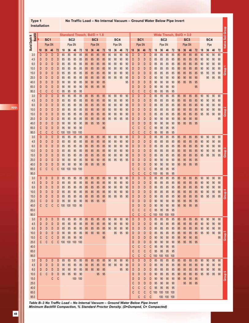
48
18 36 46 72 18 36 46 72 18 36 46 72 18 36 46 72 18 36 46 72 18 36 46 72 18 36 46 72 18 36 46 72 3.0 D D D D 85 85 85 85 85 85 85 85 90 90 90 90 D D D D 85 85 85 85 85 85 85 85 90 90 90 90 4.5 D D D D 85 85 85 85 85 85 85 85 90 90 90 90 D D D D 85 85 85 85 85 85 85 85 90 90 90 90 6.0 D D D D 85 85 85 85 85 85 85 85 90 90 90 90 D D D D 85 85 85 85 85 85 85 85 90 90 90 90 10.0 D D D D 85 85 85 85 85 85 85 85 90 90 90 90 D D D D 85 85 85 85 85 85 85 85 90 90 90 90 15.0 D D D D 85 85 85 85 85 85 85 85 90 90 90 90 D D D D 85 85 85 85 85 85 85 85 95 95 95 90 25.0 D D D D 85 85 85 85 85 85 85 85 95 95 95 95 D D D D 90 90 90 90 90 90 90 90 95 95 95 40.0 D D D D 90 90 90 85 90 90 90 85 95 D D D D 90 90 90 90 95 95 95 95 65.0 D D D D 90 90 90 90 95 95 95 95 D D D D 90 90 90 90 95 95.0 C C C C 95 95 95 95 C C C C 95 95 95 95 3.0 D D D D 85 85 85 85 85 85 85 85 90 90 90 90 D D D D 85 85 85 85 85 85 85 85 90 90 90 90 4.5 D D D D 85 85 85 85 85 85 85 85 90 90 90 90 D D D D 85 85 85 85 85 85 85 85 90 90 90 90 6.0 D D D D 85 85 85 85 85 85 85 85 90 90 90 90 D D D D 85 85 85 85 85 85 85 85 90 90 90 90 10.0 D D D D 85 85 85 85 85 85 85 85 90 90 90 90 D D D D 85 85 85 85 85 85 85 85 90 90 90 90 15.0 D D D D 85 85 85 85 85 85 85 85 90 90 90 90 D D D D 85 85 85 85 85 85 85 85 95 95 90 90 25.0 D D D D 85 85 85 85 85 85 85 85 95 95 95 95 D D D D 90 90 90 90 95 90 90 90 95 40.0 D D D D 90 90 90 90 95 95 95 90 D D D D 90 90 90 90 95 95 95 95 65.0 C D D D 95 90 90 90 95 C C C C 95 95 95 95 95.0 C C C C 100 100 100 100 C C C C 95 95 95 95 3.0 D D D D 85 85 85 85 85 85 85 85 90 90 90 90 D D D D 85 85 85 85 85 85 85 85 90 90 90 90 4.5 D D D D 85 85 85 85 85 85 85 85 90 90 90 90 D D D D 85 85 85 85 85 85 85 85 90 90 90 90 6.0 D D D D 85 85 85 85 85 85 85 85 90 90 90 90 D D D D 85 85 85 85 85 85 85 85 90 90 90 90 10.0 D D D D 85 85 85 85 85 85 85 85 90 90 90 90 D D D D 85 85 85 85 85 85 85 85 90 90 90 90 15.0 D D D D 85 85 85 85 85 85 85 85 90 90 90 90 D D D D 85 85 85 85 85 85 85 85 95 95 95 95 25.0 D D D D 90 90 90 85 90 90 90 85 95 95 95 95 D D D D 90 90 90 90 95 95 95 95 40.0 D D D D 90 90 90 90 95 95 95 95 D D D D 90 90 90 90 95 95 95 95 65.0 C C C C 100 100 100 100 C C C C 95 95 95 95 95.0 C C C C 100 95 95 95 3.0 D D D D 85 85 85 85 85 85 85 85 90 90 90 90 D D D D 85 85 85 85 85 85 85 85 90 90 90 90 4.5 D D D D 85 85 85 85 85 85 85 85 90 90 90 90 D D D D 85 85 85 85 85 85 85 85 90 90 90 90 6.0 D D D D 85 85 85 85 85 85 85 85 90 90 90 90 D D D D 85 85 85 85 85 85 85 85 90 90 90 90 10.0 D D D D 85 85 85 85 85 85 85 85 90 90 90 90 D D D D 85 85 85 85 85 85 85 85 90 90 90 90 15.0 D D D D 85 85 85 85 85 85 85 85 95 95 95 90 D D D D 90 85 85 85 90 85 85 85 95 95 95 95 25.0 C D D D 95 90 90 90 95 95 95 95 D D D D 90 90 90 90 95 95 95 95 40.0 C C C C 100 100 100 95 D D D D 90 90 90 90 95 95 95 95 65.0 C C C C 95 95 95 95 95.0 C C C C 100 100 100 100 3.0 D D D D 85 85 85 85 85 85 85 85 90 90 90 90 D D D D 85 85 85 85 85 85 85 85 90 90 90 90 4.5 D D D D 85 85 85 85 85 85 85 85 90 90 90 90 D D D D 85 85 85 85 85 85 85 85 90 90 90 90 6.0 D D D D 85 85 85 85 85 85 85 85 90 90 90 90 D D D D 85 85 85 85 85 85 85 85 90 90 90 90 10.0 D D D D 90 90 85 85 95 90 90 85 95 95 90 D D D D 85 85 85 85 85 85 85 85 95 90 90 90 15.0 C C C D 95 95 95 90 95 D D D D 90 90 90 85 95 90 90 85 95 25.0 C C C C 100 100 100 100 D D D D 90 90 90 90 95 95 95 95 40.0 C C C C 95 95 95 95 65.0 C C C C 95 95 95 95 95.0 C C C C 100 100 100 100 3.0 D D D D 85 85 85 85 85 85 85 85 90 90 90 90 D D D D 85 85 85 85 85 85 85 85 90 90 90 90 4.5 D D D D 90 85 85 85 90 85 85 85 95 90 90 90 D D D D 85 85 85 85 85 85 85 85 90 90 90 90 6.0 D D D D 90 90 90 85 95 90 90 85 95 90 D D D D 85 85 85 85 85 85 85 85 90 90 90 90 10.0 C C D D 95 95 90 90 95 95 D D D D 90 85 85 85 90 85 85 85 95 95 95 90 15.0 C C 100 100 D D D D 90 90 90 90 95 95 95 95 25.0 C D D D 95 90 90 90 95 95 95 40.0 C C C C 95 95 95 95 65.0 C C C C 100 100 100 100 95.0 C C C 100 100 100
Buria
l Dep
th ft
Type 1 No Traffic Load – No Internal Vacuum – Ground Water Below Pipe InvertInstallation
SC1 SC2 SC3 SC4 SC1 SC2 SC3 SC4Pipe SN Pipe SN Pipe SN Pipe SN Pipe SN Pipe SN Pipe SN Pipe
Standard Trench, Bd/D = 1.8 Wide Trench, Bd/D = 3.0 B
ackfi
ll
Grou
p 6
Gro
up 5
Gro
up 4
Gro
up 3
Grou
p 2
Grou
p 1
Nat
ive S
oil G
roup
Table B–3 No Traffic Load – No Internal Vacuum – Ground Water Below Pipe Invert Minimum Backfill Compaction, % Standard Proctor Density. (D=Dumped, C= Compacted)
app.
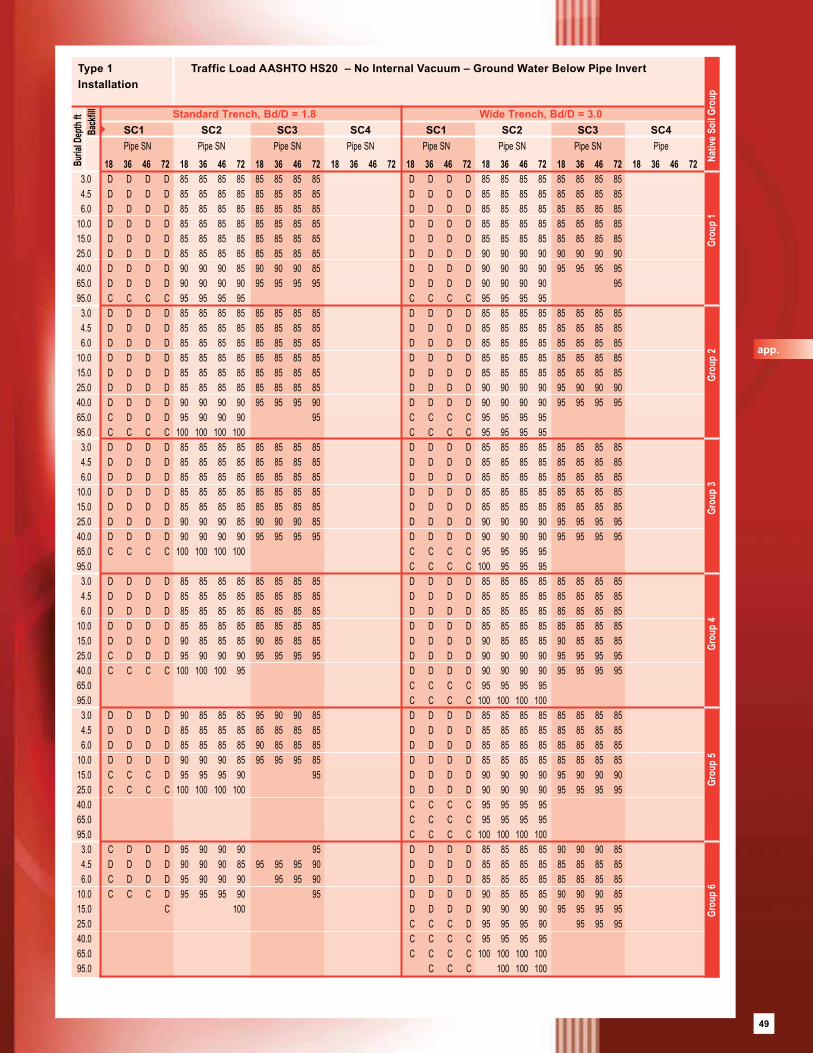
49
18 36 46 72 18 36 46 72 18 36 46 72 18 36 46 72 18 36 46 72 18 36 46 72 18 36 46 72 18 36 46 72 3.0 D D D D 85 85 85 85 85 85 85 85 D D D D 85 85 85 85 85 85 85 85 4.5 D D D D 85 85 85 85 85 85 85 85 D D D D 85 85 85 85 85 85 85 85 6.0 D D D D 85 85 85 85 85 85 85 85 D D D D 85 85 85 85 85 85 85 85 10.0 D D D D 85 85 85 85 85 85 85 85 D D D D 85 85 85 85 85 85 85 85 15.0 D D D D 85 85 85 85 85 85 85 85 D D D D 85 85 85 85 85 85 85 85 25.0 D D D D 85 85 85 85 85 85 85 85 D D D D 90 90 90 90 90 90 90 90 40.0 D D D D 90 90 90 85 90 90 90 85 D D D D 90 90 90 90 95 95 95 95 65.0 D D D D 90 90 90 90 95 95 95 95 D D D D 90 90 90 90 95 95.0 C C C C 95 95 95 95 C C C C 95 95 95 95 3.0 D D D D 85 85 85 85 85 85 85 85 D D D D 85 85 85 85 85 85 85 85 4.5 D D D D 85 85 85 85 85 85 85 85 D D D D 85 85 85 85 85 85 85 85 6.0 D D D D 85 85 85 85 85 85 85 85 D D D D 85 85 85 85 85 85 85 85 10.0 D D D D 85 85 85 85 85 85 85 85 D D D D 85 85 85 85 85 85 85 85 15.0 D D D D 85 85 85 85 85 85 85 85 D D D D 85 85 85 85 85 85 85 85 25.0 D D D D 85 85 85 85 85 85 85 85 D D D D 90 90 90 90 95 90 90 90 40.0 D D D D 90 90 90 90 95 95 95 90 D D D D 90 90 90 90 95 95 95 95 65.0 C D D D 95 90 90 90 95 C C C C 95 95 95 95 95.0 C C C C 100 100 100 100 C C C C 95 95 95 95 3.0 D D D D 85 85 85 85 85 85 85 85 D D D D 85 85 85 85 85 85 85 85 4.5 D D D D 85 85 85 85 85 85 85 85 D D D D 85 85 85 85 85 85 85 85 6.0 D D D D 85 85 85 85 85 85 85 85 D D D D 85 85 85 85 85 85 85 85 10.0 D D D D 85 85 85 85 85 85 85 85 D D D D 85 85 85 85 85 85 85 85 15.0 D D D D 85 85 85 85 85 85 85 85 D D D D 85 85 85 85 85 85 85 85 25.0 D D D D 90 90 90 85 90 90 90 85 D D D D 90 90 90 90 95 95 95 95 40.0 D D D D 90 90 90 90 95 95 95 95 D D D D 90 90 90 90 95 95 95 95 65.0 C C C C 100 100 100 100 C C C C 95 95 95 95 95.0 C C C C 100 95 95 95 3.0 D D D D 85 85 85 85 85 85 85 85 D D D D 85 85 85 85 85 85 85 85 4.5 D D D D 85 85 85 85 85 85 85 85 D D D D 85 85 85 85 85 85 85 85 6.0 D D D D 85 85 85 85 85 85 85 85 D D D D 85 85 85 85 85 85 85 85 10.0 D D D D 85 85 85 85 85 85 85 85 D D D D 85 85 85 85 85 85 85 85 15.0 D D D D 90 85 85 85 90 85 85 85 D D D D 90 85 85 85 90 85 85 85 25.0 C D D D 95 90 90 90 95 95 95 95 D D D D 90 90 90 90 95 95 95 95 40.0 C C C C 100 100 100 95 D D D D 90 90 90 90 95 95 95 95 65.0 C C C C 95 95 95 95 95.0 C C C C 100 100 100 100 3.0 D D D D 90 85 85 85 95 90 90 85 D D D D 85 85 85 85 85 85 85 85 4.5 D D D D 85 85 85 85 85 85 85 85 D D D D 85 85 85 85 85 85 85 85 6.0 D D D D 85 85 85 85 90 85 85 85 D D D D 85 85 85 85 85 85 85 85 10.0 D D D D 90 90 90 85 95 95 95 85 D D D D 85 85 85 85 85 85 85 85 15.0 C C C D 95 95 95 90 95 D D D D 90 90 90 90 95 90 90 90 25.0 C C C C 100 100 100 100 D D D D 90 90 90 90 95 95 95 95 40.0 C C C C 95 95 95 95 65.0 C C C C 95 95 95 95 95.0 C C C C 100 100 100 100 3.0 C D D D 95 90 90 90 95 D D D D 85 85 85 85 90 90 90 85 4.5 D D D D 90 90 90 85 95 95 95 90 D D D D 85 85 85 85 85 85 85 85 6.0 C D D D 95 90 90 90 95 95 90 D D D D 85 85 85 85 85 85 85 85 10.0 C C C D 95 95 95 90 95 D D D D 90 85 85 85 90 90 90 85 15.0 C 100 D D D D 90 90 90 90 95 95 95 95 25.0 C C C D 95 95 95 90 95 95 95 40.0 C C C C 95 95 95 95 65.0 C C C C 100 100 100 100 95.0 C C C 100 100 100
Buria
l Dep
th ft
Type 1 Traffic Load AASHTO HS20 – No Internal Vacuum – Ground Water Below Pipe InvertInstallation
SC1 SC2 SC3 SC4 SC1 SC2 SC3 SC4Pipe SN Pipe SN Pipe SN Pipe SN Pipe SN Pipe SN Pipe SN Pipe
Standard Trench, Bd/D = 1.8 Wide Trench, Bd/D = 3.0
Bac
kfill
Grou
p 6
Gro
up 5
Gro
up 4
Gro
up 3
Grou
p 2
Grou
p 1
Nativ
e Soi
l Gro
up
app.
49
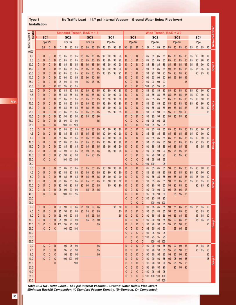
50
3.0 D D D D 85 85 85 85 85 85 85 85 90 90 90 90 D D D D 85 85 85 85 85 85 85 85 95 90 90 90 4.5 D D D D 85 85 85 85 85 85 85 85 90 90 90 90 D D D D 85 85 85 85 85 85 85 85 95 90 90 90 6.0 D D D D 85 85 85 85 85 85 85 85 90 90 90 90 D D D D 85 85 85 85 85 85 85 85 95 90 90 90 10.0 D D D D 85 85 85 85 85 85 85 85 95 90 90 90 D D D D 85 85 85 85 85 85 85 85 95 95 90 90 15.0 D D D D 85 85 85 85 85 85 85 85 95 90 90 90 D D D D 90 85 85 85 90 85 85 85 95 95 95 90 25.0 D D D D 90 85 85 85 90 85 85 85 95 95 95 95 D D D D 90 90 90 90 95 90 90 90 95 95 95 40.0 D D D D 90 90 90 85 95 90 90 85 95 D D D D 90 90 90 90 95 95 95 95 65.0 C D D D 95 90 90 90 95 95 95 C D D D 95 90 90 90 95 95.0 C C C C 100 95 95 95 C C C C 100 95 95 95 3.0 D D D D 85 85 85 85 85 85 85 85 90 90 90 90 D D D D 85 85 85 85 85 85 85 85 95 90 90 90 4.5 D D D D 85 85 85 85 85 85 85 85 90 90 90 90 D D D D 85 85 85 85 85 85 85 85 95 90 90 90 6.0 D D D D 85 85 85 85 85 85 85 85 90 90 90 90 D D D D 85 85 85 85 85 85 85 85 95 90 90 90 10.0 D D D D 85 85 85 85 85 85 85 85 95 90 90 90 D D D D 85 85 85 85 85 85 85 85 95 95 90 90 15.0 D D D D 85 85 85 85 85 85 85 85 95 90 90 90 D D D D 90 85 85 85 90 85 85 85 95 95 90 25.0 D D D D 90 85 85 85 90 85 85 85 95 95 95 D D D D 90 90 90 90 95 90 90 90 95 40.0 D D D D 90 90 90 90 95 95 95 90 D D D D 90 90 90 90 95 95 95 95 65.0 C D D D 95 90 90 90 95 C C C C 95 95 95 95 95.0 C C C 100 100 100 C C C C 100 95 95 95 3.0 D D D D 85 85 85 85 85 85 85 85 90 90 90 90 D D D D 85 85 85 85 85 85 85 85 95 90 90 90 4.5 D D D D 85 85 85 85 85 85 85 85 90 90 90 90 D D D D 85 85 85 85 85 85 85 85 95 90 90 90 6.0 D D D D 85 85 85 85 85 85 85 85 90 90 90 90 D D D D 85 85 85 85 85 85 85 85 95 90 90 90 10.0 D D D D 85 85 85 85 85 85 85 85 95 90 90 90 D D D D 90 85 85 85 90 85 85 85 95 95 95 90 15.0 D D D D 90 85 85 85 90 85 85 85 95 95 95 90 D D D D 90 85 85 85 95 85 85 85 95 95 95 25.0 D D D D 90 90 90 85 95 90 85 85 95 95 95 D D D D 90 90 90 90 95 95 95 95 40.0 C D D D 95 90 90 90 95 95 95 C D D D 95 90 90 90 95 95 95 65.0 C C C 100 100 100 C C C C 95 95 95 95 95.0 C C C C 100 100 95 3.0 D D D D 85 85 85 85 85 85 85 85 95 90 90 90 D D D D 85 85 85 85 90 85 85 85 95 90 90 90 4.5 D D D D 85 85 85 85 85 85 85 85 95 90 90 90 D D D D 85 85 85 85 85 85 85 85 95 95 90 90 6.0 D D D D 85 85 85 85 85 85 85 85 95 90 90 90 D D D D 90 85 85 85 90 85 85 85 95 95 90 90 10.0 D D D D 90 85 85 85 90 85 85 85 95 90 90 90 D D D D 90 85 85 85 90 85 85 85 95 95 95 90 15.0 D D D D 90 90 90 85 95 90 85 85 95 95 90 D D D D 90 90 90 85 95 90 85 85 95 95 95 25.0 C D D D 95 90 90 90 95 95 95 D D D D 90 90 90 90 95 95 95 95 40.0 C C C 100 100 95 C D D D 95 90 90 90 95 95 95 65.0 C C C C 100 95 95 95 95.0 C C C 100 100 100 3.0 D D D D 90 90 90 85 95 90 90 85 95 90 D D D D 90 85 85 85 90 85 85 85 95 95 95 90 4.5 C D D D 95 90 90 85 95 95 90 85 95 D D D D 90 85 85 85 90 85 85 85 95 95 90 6.0 C D D D 95 90 90 85 95 95 85 95 D D D D 90 85 85 85 90 85 85 85 95 95 90 10.0 C D D D 95 90 90 90 95 95 90 D D D D 90 90 90 85 95 90 85 85 95 95 95 15.0 C C C D 100 95 95 90 95 D D D D 90 90 90 85 95 95 90 85 95 25.0 C C C 100 100 100 C D D D 95 90 90 90 95 95 95 40.0 C C C C 95 95 95 95 65.0 C C C C 100 95 95 95 95.0 C C C 100 100 100 3.0 C C D 95 95 90 95 D D D D 90 90 90 85 95 90 90 85 95 95 95 4.5 C C D 95 95 90 95 D D D D 90 90 90 85 95 90 90 85 95 95 95 6.0 C C C 95 95 95 95 D D D D 90 90 90 85 95 90 90 85 95 10.0 C C C 100 100 95 D D D D 90 90 90 85 95 95 90 85 95 15.0 C 100 C D D D 95 90 90 90 95 95 95 95 25.0 C D D D 95 90 90 90 95 95 95 40.0 C C C C 100 95 95 95 65.0 C C C C 100 100 100 100 95.0 C C 100 100
Buria
l Dep
th ft
Type 1 No Traffic Load – 14.7 psi Internal Vacuum – Ground Water Below Pipe InvertInstallation
SC1 SC2 SC3 SC4 SC1 SC2 SC3 SC4Pipe SN Pipe SN Pipe SN Pipe SN Pipe SN Pipe SN Pipe SN Pipe
Standard Trench, Bd/D = 1.8 Wide Trench, Bd/D = 3.0 B
ackfi
ll
Grou
p 6
Gro
up 5
Gro
up 4
Gro
up 3
Grou
p 2
Grou
p 1
Nativ
e Soi
l Gro
up
Table B–5 No Traffic Load – 14.7 psi Internal Vacuum – Ground Water Below Pipe InvertMinimum Backfill Compaction, % Standard Proctor Density. (D=Dumped, C= Compacted)
app.
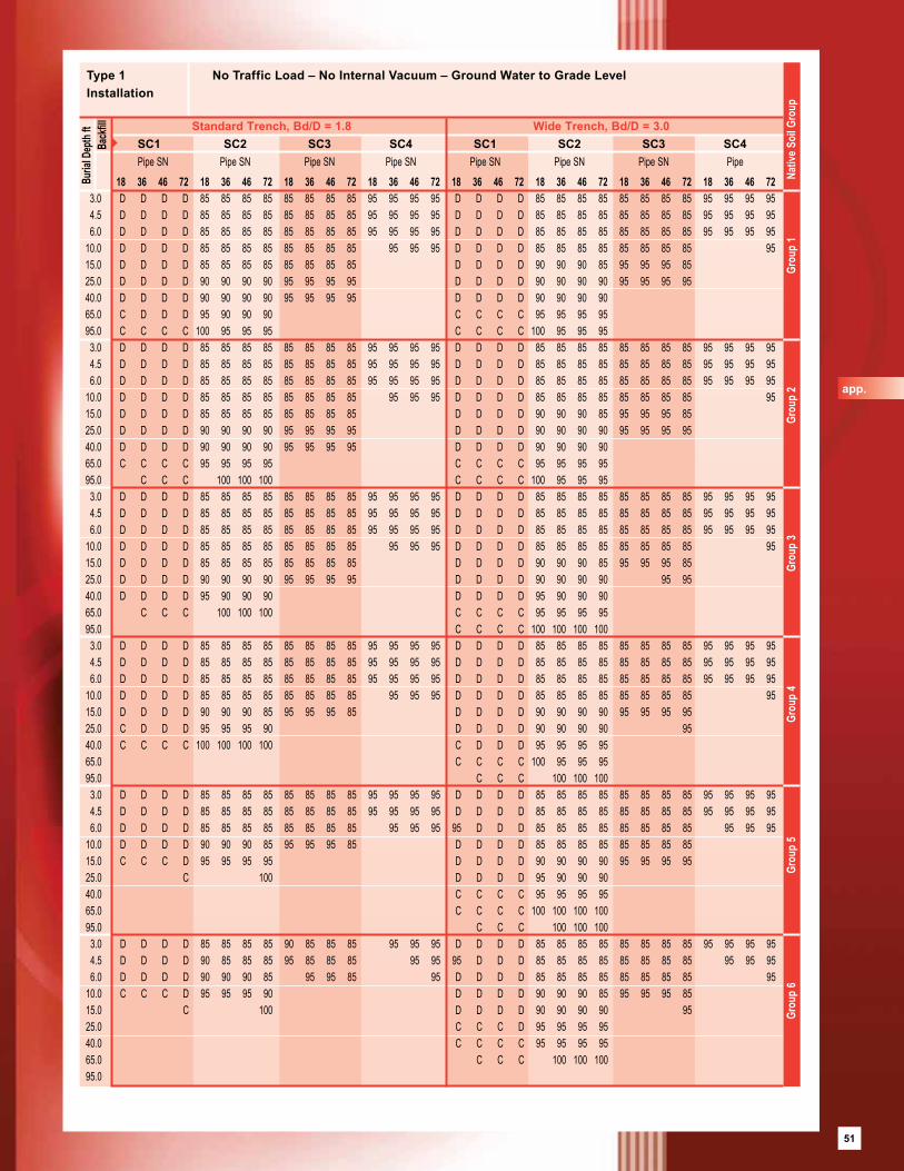
51
18 36 46 72 18 36 46 72 18 36 46 72 18 36 46 72 18 36 46 72 18 36 46 72 18 36 46 72 18 36 46 72 3.0 D D D D 85 85 85 85 85 85 85 85 95 95 95 95 D D D D 85 85 85 85 85 85 85 85 95 95 95 95 4.5 D D D D 85 85 85 85 85 85 85 85 95 95 95 95 D D D D 85 85 85 85 85 85 85 85 95 95 95 95 6.0 D D D D 85 85 85 85 85 85 85 85 95 95 95 95 D D D D 85 85 85 85 85 85 85 85 95 95 95 95 10.0 D D D D 85 85 85 85 85 85 85 85 95 95 95 D D D D 85 85 85 85 85 85 85 85 95 15.0 D D D D 85 85 85 85 85 85 85 85 D D D D 90 90 90 85 95 95 95 85 25.0 D D D D 90 90 90 90 95 95 95 95 D D D D 90 90 90 90 95 95 95 95 40.0 D D D D 90 90 90 90 95 95 95 95 D D D D 90 90 90 90 65.0 C D D D 95 90 90 90 C C C C 95 95 95 95 95.0 C C C C 100 95 95 95 C C C C 100 95 95 95 3.0 D D D D 85 85 85 85 85 85 85 85 95 95 95 95 D D D D 85 85 85 85 85 85 85 85 95 95 95 95 4.5 D D D D 85 85 85 85 85 85 85 85 95 95 95 95 D D D D 85 85 85 85 85 85 85 85 95 95 95 95 6.0 D D D D 85 85 85 85 85 85 85 85 95 95 95 95 D D D D 85 85 85 85 85 85 85 85 95 95 95 95 10.0 D D D D 85 85 85 85 85 85 85 85 95 95 95 D D D D 85 85 85 85 85 85 85 85 95 15.0 D D D D 85 85 85 85 85 85 85 85 D D D D 90 90 90 85 95 95 95 85 25.0 D D D D 90 90 90 90 95 95 95 95 D D D D 90 90 90 90 95 95 95 95 40.0 D D D D 90 90 90 90 95 95 95 95 D D D D 90 90 90 90 65.0 C C C C 95 95 95 95 C C C C 95 95 95 95 95.0 C C C 100 100 100 C C C C 100 95 95 95 3.0 D D D D 85 85 85 85 85 85 85 85 95 95 95 95 D D D D 85 85 85 85 85 85 85 85 95 95 95 95 4.5 D D D D 85 85 85 85 85 85 85 85 95 95 95 95 D D D D 85 85 85 85 85 85 85 85 95 95 95 95 6.0 D D D D 85 85 85 85 85 85 85 85 95 95 95 95 D D D D 85 85 85 85 85 85 85 85 95 95 95 95 10.0 D D D D 85 85 85 85 85 85 85 85 95 95 95 D D D D 85 85 85 85 85 85 85 85 95 15.0 D D D D 85 85 85 85 85 85 85 85 D D D D 90 90 90 85 95 95 95 85 25.0 D D D D 90 90 90 90 95 95 95 95 D D D D 90 90 90 90 95 95 40.0 D D D D 95 90 90 90 D D D D 95 90 90 90 65.0 C C C 100 100 100 C C C C 95 95 95 95 95.0 C C C C 100 100 100 100 3.0 D D D D 85 85 85 85 85 85 85 85 95 95 95 95 D D D D 85 85 85 85 85 85 85 85 95 95 95 95 4.5 D D D D 85 85 85 85 85 85 85 85 95 95 95 95 D D D D 85 85 85 85 85 85 85 85 95 95 95 95 6.0 D D D D 85 85 85 85 85 85 85 85 95 95 95 95 D D D D 85 85 85 85 85 85 85 85 95 95 95 95 10.0 D D D D 85 85 85 85 85 85 85 85 95 95 95 D D D D 85 85 85 85 85 85 85 85 95 15.0 D D D D 90 90 90 85 95 95 95 85 D D D D 90 90 90 90 95 95 95 95 25.0 C D D D 95 95 95 90 D D D D 90 90 90 90 95 40.0 C C C C 100 100 100 100 C D D D 95 95 95 95 65.0 C C C C 100 95 95 95 95.0 C C C 100 100 100 3.0 D D D D 85 85 85 85 85 85 85 85 95 95 95 95 D D D D 85 85 85 85 85 85 85 85 95 95 95 95 4.5 D D D D 85 85 85 85 85 85 85 85 95 95 95 95 D D D D 85 85 85 85 85 85 85 85 95 95 95 95 6.0 D D D D 85 85 85 85 85 85 85 85 95 95 95 95 D D D 85 85 85 85 85 85 85 85 95 95 95 10.0 D D D D 90 90 90 85 95 95 95 85 D D D D 85 85 85 85 85 85 85 85 15.0 C C C D 95 95 95 95 D D D D 90 90 90 90 95 95 95 95 25.0 C 100 D D D D 95 90 90 90 40.0 C C C C 95 95 95 95 65.0 C C C C 100 100 100 100 95.0 C C C 100 100 100 3.0 D D D D 85 85 85 85 90 85 85 85 95 95 95 D D D D 85 85 85 85 85 85 85 85 95 95 95 95 4.5 D D D D 90 85 85 85 95 85 85 85 95 95 95 D D D 85 85 85 85 85 85 85 85 95 95 95 6.0 D D D D 90 90 90 85 95 95 85 95 D D D D 85 85 85 85 85 85 85 85 95 10.0 C C C D 95 95 95 90 D D D D 90 90 90 85 95 95 95 85 15.0 C 100 D D D D 90 90 90 90 95 25.0 C C C D 95 95 95 95 40.0 C C C C 95 95 95 95 65.0 C C C 100 100 100 95.0
Buria
l Dep
th ft
Type 1 No Traffic Load – No Internal Vacuum – Ground Water to Grade LevelInstallation
SC1 SC2 SC3 SC4 SC1 SC2 SC3 SC4Pipe SN Pipe SN Pipe SN Pipe SN Pipe SN Pipe SN Pipe SN Pipe
Standard Trench, Bd/D = 1.8 Wide Trench, Bd/D = 3.0
Bac
kfill
Grou
p 6
Gro
up 5
Gro
up 4
Gro
up 3
Grou
p 2
Grou
p 1
Nativ
e Soi
l Gro
up
app.
51
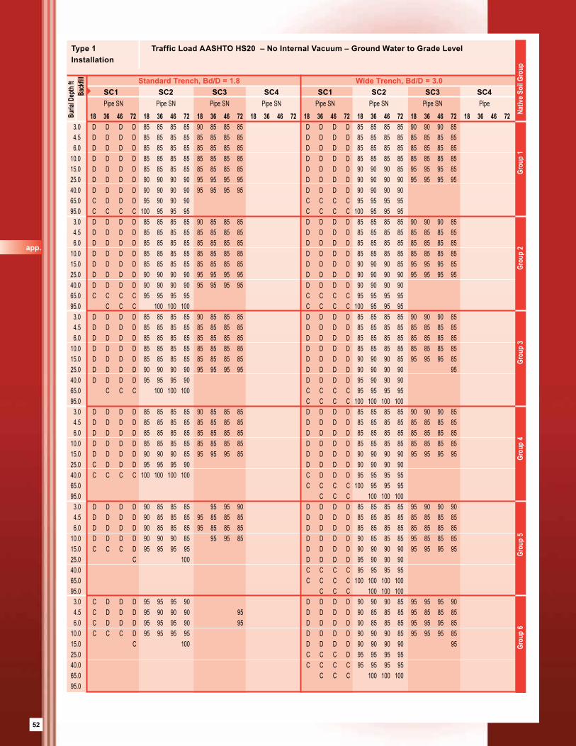
52
18 36 46 72 18 36 46 72 18 36 46 72 18 36 46 72 18 36 46 72 18 36 46 72 18 36 46 72 18 36 46 72 3.0 D D D D 85 85 85 85 90 85 85 85 D D D D 85 85 85 85 90 90 90 85 4.5 D D D D 85 85 85 85 85 85 85 85 D D D D 85 85 85 85 85 85 85 85 6.0 D D D D 85 85 85 85 85 85 85 85 D D D D 85 85 85 85 85 85 85 85 10.0 D D D D 85 85 85 85 85 85 85 85 D D D D 85 85 85 85 85 85 85 85 15.0 D D D D 85 85 85 85 85 85 85 85 D D D D 90 90 90 85 95 95 95 85 25.0 D D D D 90 90 90 90 95 95 95 95 D D D D 90 90 90 90 95 95 95 95 40.0 D D D D 90 90 90 90 95 95 95 95 D D D D 90 90 90 90 65.0 C D D D 95 90 90 90 C C C C 95 95 95 95 95.0 C C C C 100 95 95 95 C C C C 100 95 95 95 3.0 D D D D 85 85 85 85 90 85 85 85 D D D D 85 85 85 85 90 90 90 85 4.5 D D D D 85 85 85 85 85 85 85 85 D D D D 85 85 85 85 85 85 85 85 6.0 D D D D 85 85 85 85 85 85 85 85 D D D D 85 85 85 85 85 85 85 85 10.0 D D D D 85 85 85 85 85 85 85 85 D D D D 85 85 85 85 85 85 85 85 15.0 D D D D 85 85 85 85 85 85 85 85 D D D D 90 90 90 85 95 95 95 85 25.0 D D D D 90 90 90 90 95 95 95 95 D D D D 90 90 90 90 95 95 95 95 40.0 D D D D 90 90 90 90 95 95 95 95 D D D D 90 90 90 90 65.0 C C C C 95 95 95 95 C C C C 95 95 95 95 95.0 C C C 100 100 100 C C C C 100 95 95 95 3.0 D D D D 85 85 85 85 90 85 85 85 D D D D 85 85 85 85 90 90 90 85 4.5 D D D D 85 85 85 85 85 85 85 85 D D D D 85 85 85 85 85 85 85 85 6.0 D D D D 85 85 85 85 85 85 85 85 D D D D 85 85 85 85 85 85 85 85 10.0 D D D D 85 85 85 85 85 85 85 85 D D D D 85 85 85 85 85 85 85 85 15.0 D D D D 85 85 85 85 85 85 85 85 D D D D 90 90 90 85 95 95 95 85 25.0 D D D D 90 90 90 90 95 95 95 95 D D D D 90 90 90 90 95 40.0 D D D D 95 95 95 90 D D D D 95 90 90 90 65.0 C C C 100 100 100 C C C C 95 95 95 95 95.0 C C C C 100 100 100 100 3.0 D D D D 85 85 85 85 90 85 85 85 D D D D 85 85 85 85 90 90 90 85 4.5 D D D D 85 85 85 85 85 85 85 85 D D D D 85 85 85 85 85 85 85 85 6.0 D D D D 85 85 85 85 85 85 85 85 D D D D 85 85 85 85 85 85 85 85 10.0 D D D D 85 85 85 85 85 85 85 85 D D D D 85 85 85 85 85 85 85 85 15.0 D D D D 90 90 90 85 95 95 95 85 D D D D 90 90 90 90 95 95 95 95 25.0 C D D D 95 95 95 90 D D D D 90 90 90 90 40.0 C C C C 100 100 100 100 C D D D 95 95 95 95 65.0 C C C C 100 95 95 95 95.0 C C C 100 100 100 3.0 D D D D 90 85 85 85 95 95 90 D D D D 85 85 85 85 95 90 90 90 4.5 D D D D 90 85 85 85 95 85 85 85 D D D D 85 85 85 85 85 85 85 85 6.0 D D D D 90 85 85 85 95 85 85 85 D D D D 85 85 85 85 85 85 85 85 10.0 D D D D 90 90 90 85 95 95 85 D D D D 90 85 85 85 95 85 85 85 15.0 C C C D 95 95 95 95 D D D D 90 90 90 90 95 95 95 95 25.0 C 100 D D D D 95 90 90 90 40.0 C C C C 95 95 95 95 65.0 C C C C 100 100 100 100 95.0 C C C 100 100 100 3.0 C D D D 95 95 95 90 D D D D 90 90 90 85 95 95 95 90 4.5 C D D D 95 90 90 90 95 D D D D 90 85 85 85 95 85 85 85 6.0 C D D D 95 95 95 90 95 D D D D 90 85 85 85 95 95 95 85 10.0 C C C D 95 95 95 95 D D D D 90 90 90 85 95 95 95 85 15.0 C 100 D D D D 90 90 90 90 95 25.0 C C C D 95 95 95 95 40.0 C C C C 95 95 95 95 65.0 C C C 100 100 100 95.0
Buria
l Dep
th ft
Type 1 Traffic Load AASHTO HS20 – No Internal Vacuum – Ground Water to Grade LevelInstallation
SC1 SC2 SC3 SC4 SC1 SC2 SC3 SC4Pipe SN Pipe SN Pipe SN Pipe SN Pipe SN Pipe SN Pipe SN Pipe
Standard Trench, Bd/D = 1.8 Wide Trench, Bd/D = 3.0 B
ackfi
ll
Grou
p 6
Gro
up 5
Gro
up 4
Gro
up 3
Grou
p 2
Grou
p 1
Nativ
e Soi
l Gro
up
app.
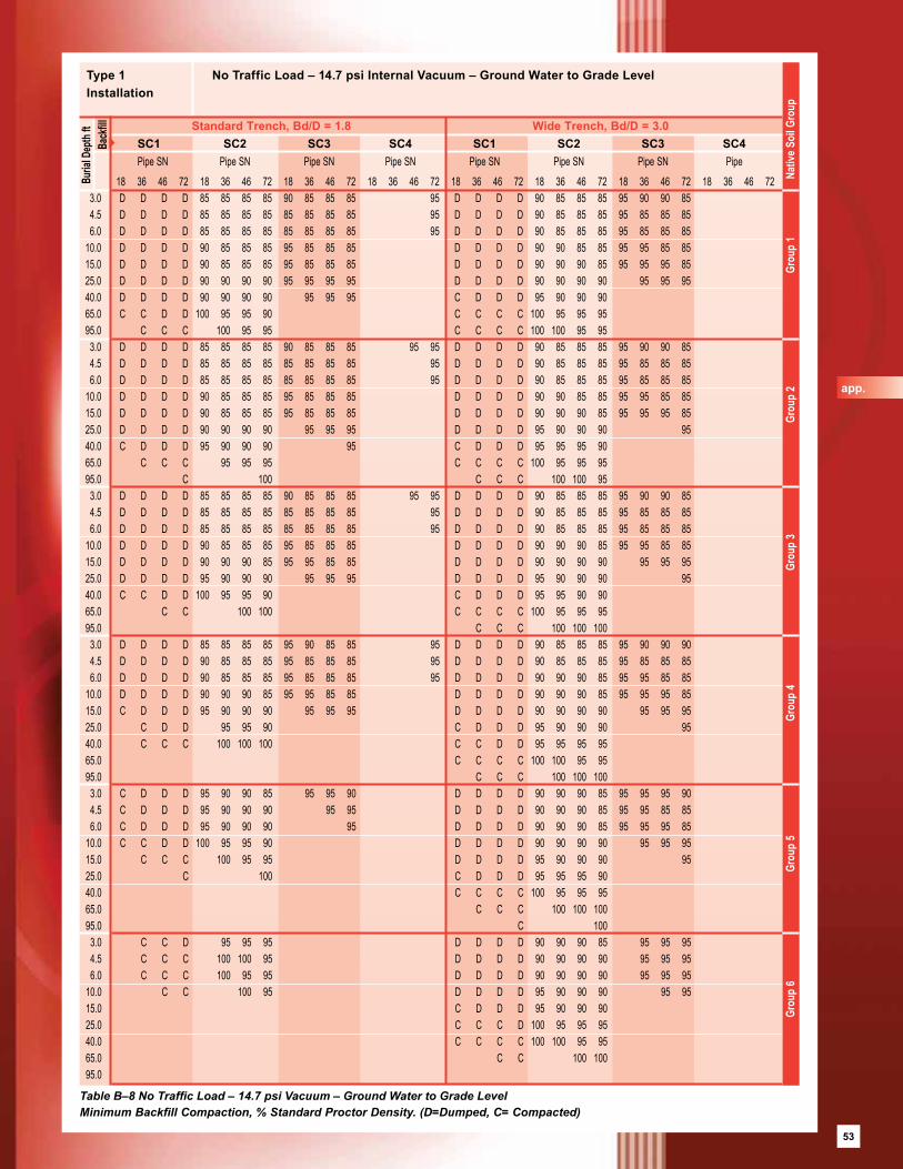
53
18 36 46 72 18 36 46 72 18 36 46 72 18 36 46 72 18 36 46 72 18 36 46 72 18 36 46 72 18 36 46 72 3.0 D D D D 85 85 85 85 90 85 85 85 95 D D D D 90 85 85 85 95 90 90 85 4.5 D D D D 85 85 85 85 85 85 85 85 95 D D D D 90 85 85 85 95 85 85 85 6.0 D D D D 85 85 85 85 85 85 85 85 95 D D D D 90 85 85 85 95 85 85 85 10.0 D D D D 90 85 85 85 95 85 85 85 D D D D 90 90 85 85 95 95 85 85 15.0 D D D D 90 85 85 85 95 85 85 85 D D D D 90 90 90 85 95 95 95 85 25.0 D D D D 90 90 90 90 95 95 95 95 D D D D 90 90 90 90 95 95 95 40.0 D D D D 90 90 90 90 95 95 95 C D D D 95 90 90 90 65.0 C C D D 100 95 95 90 C C C C 100 95 95 95 95.0 C C C 100 95 95 C C C C 100 100 95 95 3.0 D D D D 85 85 85 85 90 85 85 85 95 95 D D D D 90 85 85 85 95 90 90 85 4.5 D D D D 85 85 85 85 85 85 85 85 95 D D D D 90 85 85 85 95 85 85 85 6.0 D D D D 85 85 85 85 85 85 85 85 95 D D D D 90 85 85 85 95 85 85 85 10.0 D D D D 90 85 85 85 95 85 85 85 D D D D 90 90 85 85 95 95 85 85 15.0 D D D D 90 85 85 85 95 85 85 85 D D D D 90 90 90 85 95 95 95 85 25.0 D D D D 90 90 90 90 95 95 95 D D D D 95 90 90 90 95 40.0 C D D D 95 90 90 90 95 C D D D 95 95 95 90 65.0 C C C 95 95 95 C C C C 100 95 95 95 95.0 C 100 C C C 100 100 95 3.0 D D D D 85 85 85 85 90 85 85 85 95 95 D D D D 90 85 85 85 95 90 90 85 4.5 D D D D 85 85 85 85 85 85 85 85 95 D D D D 90 85 85 85 95 85 85 85 6.0 D D D D 85 85 85 85 85 85 85 85 95 D D D D 90 85 85 85 95 85 85 85 10.0 D D D D 90 85 85 85 95 85 85 85 D D D D 90 90 90 85 95 95 85 85 15.0 D D D D 90 90 90 85 95 95 85 85 D D D D 90 90 90 90 95 95 95 25.0 D D D D 95 90 90 90 95 95 95 D D D D 95 90 90 90 95 40.0 C C D D 100 95 95 90 C D D D 95 95 90 90 65.0 C C 100 100 C C C C 100 95 95 95 95.0 C C C 100 100 100 3.0 D D D D 85 85 85 85 95 90 85 85 95 D D D D 90 85 85 85 95 90 90 90 4.5 D D D D 90 85 85 85 95 85 85 85 95 D D D D 90 85 85 85 95 85 85 85 6.0 D D D D 90 85 85 85 95 85 85 85 95 D D D D 90 90 90 85 95 95 85 85 10.0 D D D D 90 90 90 85 95 95 85 85 D D D D 90 90 90 85 95 95 95 85 15.0 C D D D 95 90 90 90 95 95 95 D D D D 90 90 90 90 95 95 95 25.0 C D D 95 95 90 C D D D 95 90 90 90 95 40.0 C C C 100 100 100 C C D D 95 95 95 95 65.0 C C C C 100 100 95 95 95.0 C C C 100 100 100 3.0 C D D D 95 90 90 85 95 95 90 D D D D 90 90 90 85 95 95 95 90 4.5 C D D D 95 90 90 90 95 95 D D D D 90 90 90 85 95 95 85 85 6.0 C D D D 95 90 90 90 95 D D D D 90 90 90 85 95 95 95 85 10.0 C C D D 100 95 95 90 D D D D 90 90 90 90 95 95 95 15.0 C C C 100 95 95 D D D D 95 90 90 90 95 25.0 C 100 C D D D 95 95 95 90 40.0 C C C C 100 95 95 95 65.0 C C C 100 100 100 95.0 C 100 3.0 C C D 95 95 95 D D D D 90 90 90 85 95 95 95 4.5 C C C 100 100 95 D D D D 90 90 90 90 95 95 95 6.0 C C C 100 95 95 D D D D 90 90 90 90 95 95 95 10.0 C C 100 95 D D D D 95 90 90 90 95 95 15.0 C D D D 95 90 90 90 25.0 C C C D 100 95 95 95 40.0 C C C C 100 100 95 95 65.0 C C 100 100 95.0
Buria
l Dep
th ft
Type 1 No Traffic Load – 14.7 psi Internal Vacuum – Ground Water to Grade LevelInstallation
SC1 SC2 SC3 SC4 SC1 SC2 SC3 SC4Pipe SN Pipe SN Pipe SN Pipe SN Pipe SN Pipe SN Pipe SN Pipe
Standard Trench, Bd/D = 1.8 Wide Trench, Bd/D = 3.0
Bac
kfill
Grou
p 6
Gro
up 5
Gro
up 4
Gro
up 3
Grou
p 2
Grou
p 1
Nativ
e Soi
l Gro
up
Table B–8 No Traffic Load – 14.7 psi Vacuum – Ground Water to Grade LevelMinimum Backfill Compaction, % Standard Proctor Density. (D=Dumped, C= Compacted)
app.
53
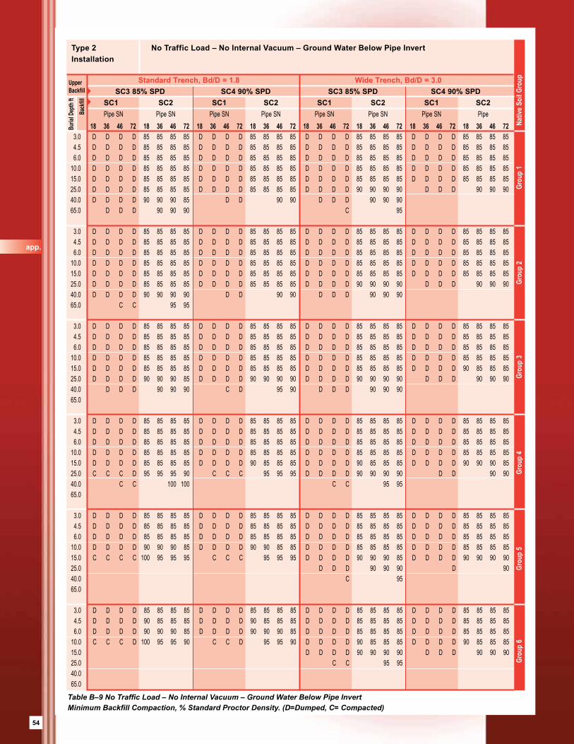
54
Table B–9 No Traffic Load – No Internal Vacuum – Ground Water Below Pipe InvertMinimum Backfill Compaction, % Standard Proctor Density. (D=Dumped, C= Compacted)
18 36 46 72 18 36 46 72 18 36 46 72 18 36 46 72 18 36 46 72 18 36 46 72 18 36 46 72 18 36 46 72 3.0 D D D D 85 85 85 85 D D D D 85 85 85 85 D D D D 85 85 85 85 D D D D 85 85 85 85 4.5 D D D D 85 85 85 85 D D D D 85 85 85 85 D D D D 85 85 85 85 D D D D 85 85 85 85 6.0 D D D D 85 85 85 85 D D D D 85 85 85 85 D D D D 85 85 85 85 D D D D 85 85 85 85 10.0 D D D D 85 85 85 85 D D D D 85 85 85 85 D D D D 85 85 85 85 D D D D 85 85 85 85 15.0 D D D D 85 85 85 85 D D D D 85 85 85 85 D D D D 85 85 85 85 D D D D 85 85 85 85 25.0 D D D D 85 85 85 85 D D D D 85 85 85 85 D D D D 90 90 90 90 D D D 90 90 90 40.0 D D D D 90 90 90 85 D D 90 90 D D D 90 90 90 65.0 D D D 90 90 90 C 95
3.0 D D D D 85 85 85 85 D D D D 85 85 85 85 D D D D 85 85 85 85 D D D D 85 85 85 85 4.5 D D D D 85 85 85 85 D D D D 85 85 85 85 D D D D 85 85 85 85 D D D D 85 85 85 85 6.0 D D D D 85 85 85 85 D D D D 85 85 85 85 D D D D 85 85 85 85 D D D D 85 85 85 85 10.0 D D D D 85 85 85 85 D D D D 85 85 85 85 D D D D 85 85 85 85 D D D D 85 85 85 85 15.0 D D D D 85 85 85 85 D D D D 85 85 85 85 D D D D 85 85 85 85 D D D D 85 85 85 85 25.0 D D D D 85 85 85 85 D D D D 85 85 85 85 D D D D 90 90 90 90 D D D 90 90 90 40.0 D D D D 90 90 90 90 D D 90 90 D D D 90 90 90 65.0 C C 95 95
3.0 D D D D 85 85 85 85 D D D D 85 85 85 85 D D D D 85 85 85 85 D D D D 85 85 85 85 4.5 D D D D 85 85 85 85 D D D D 85 85 85 85 D D D D 85 85 85 85 D D D D 85 85 85 85 6.0 D D D D 85 85 85 85 D D D D 85 85 85 85 D D D D 85 85 85 85 D D D D 85 85 85 85 10.0 D D D D 85 85 85 85 D D D D 85 85 85 85 D D D D 85 85 85 85 D D D D 85 85 85 85 15.0 D D D D 85 85 85 85 D D D D 85 85 85 85 D D D D 85 85 85 85 D D D D 90 85 85 85 25.0 D D D D 90 90 90 85 D D D D 90 90 90 90 D D D D 90 90 90 90 D D D 90 90 90 40.0 D D D 90 90 90 C D 95 90 D D D 90 90 90 65.0
3.0 D D D D 85 85 85 85 D D D D 85 85 85 85 D D D D 85 85 85 85 D D D D 85 85 85 85 4.5 D D D D 85 85 85 85 D D D D 85 85 85 85 D D D D 85 85 85 85 D D D D 85 85 85 85 6.0 D D D D 85 85 85 85 D D D D 85 85 85 85 D D D D 85 85 85 85 D D D D 85 85 85 85 10.0 D D D D 85 85 85 85 D D D D 85 85 85 85 D D D D 85 85 85 85 D D D D 85 85 85 85 15.0 D D D D 85 85 85 85 D D D D 90 85 85 85 D D D D 90 85 85 85 D D D D 90 90 90 85 25.0 C C C D 95 95 95 90 C C C 95 95 95 D D D D 90 90 90 90 D D 90 90 40.0 C C 100 100 C C 95 95 65.0
3.0 D D D D 85 85 85 85 D D D D 85 85 85 85 D D D D 85 85 85 85 D D D D 85 85 85 85 4.5 D D D D 85 85 85 85 D D D D 85 85 85 85 D D D D 85 85 85 85 D D D D 85 85 85 85 6.0 D D D D 85 85 85 85 D D D D 85 85 85 85 D D D D 85 85 85 85 D D D D 85 85 85 85 10.0 D D D D 90 90 90 85 D D D D 90 90 85 85 D D D D 85 85 85 85 D D D D 85 85 85 85 15.0 C C C C 100 95 95 95 C C C 95 95 95 D D D D 90 90 90 85 D D D D 90 90 90 90 25.0 D D D 90 90 90 D 90 40.0 C 95 65.0
3.0 D D D D 85 85 85 85 D D D D 85 85 85 85 D D D D 85 85 85 85 D D D D 85 85 85 85 4.5 D D D D 90 85 85 85 D D D D 90 85 85 85 D D D D 85 85 85 85 D D D D 85 85 85 85 6.0 D D D D 90 90 90 85 D D D D 90 90 90 85 D D D D 85 85 85 85 D D D D 85 85 85 85 10.0 C C C D 100 95 95 90 C C D 95 95 90 D D D D 90 85 85 85 D D D D 90 85 85 85 15.0 D D D D 90 90 90 90 D D D 90 90 90 25.0 C C 95 95 40.0 65.0
Type 2 No Traffic Load – No Internal Vacuum – Ground Water Below Pipe InvertInstallation
Standard Trench, Bd/D = 1.8 Wide Trench, Bd/D = 3.0
Grou
p 6
Gro
up 5
Gro
up 4
Gro
up 3
Grou
p 2
Grou
p 1
Nat
ive S
oil G
roup
SC3 85% SPD SC4 90% SPD SC3 85% SPD SC4 90% SPDSC1 SC2 SC1 SC2 SC1 SC2 SC1 SC2Pipe SN Pipe SN Pipe SN Pipe SN Pipe SN Pipe SN Pipe SN Pipe
Buria
l Dep
th ft
UpperBackfill
Back
fill
app.

55
Table B–10 No Traffic Load – 7.35 psi Internal Vacuum – Ground Water Below Pipe InvertMinimum Backfill Compaction, % Standard Proctor Density. (D=Dumped, C= Compacted)
18 36 46 72 18 36 46 72 18 36 46 72 18 36 46 72 18 36 46 72 18 36 46 72 18 36 46 72 18 36 46 72 3.0 D D D D 85 85 85 85 D D D D 85 85 85 85 D D D D 85 85 85 85 D D D D 85 85 85 85 4.5 D D D D 85 85 85 85 D D D D 85 85 85 85 D D D D 85 85 85 85 D D D D 85 85 85 85 6.0 D D D D 85 85 85 85 D D D D 85 85 85 85 D D D D 85 85 85 85 D D D D 85 85 85 85 10.0 D D D D 85 85 85 85 D D D D 85 85 85 85 D D D D 85 85 85 85 D D D D 85 85 85 85 15.0 D D D D 85 85 85 85 D D D D 85 85 85 85 D D D D 85 85 85 85 D D D 85 85 85 25.0 D D D D 85 85 85 85 D D D 85 85 85 D D D 90 90 90 D 90 40.0 D D D 90 90 85 D 90 D D 90 90 65.0 D 90 3.0 D D D D 85 85 85 85 D D D D 85 85 85 85 D D D D 85 85 85 85 D D D D 85 85 85 85 4.5 D D D D 85 85 85 85 D D D D 85 85 85 85 D D D D 85 85 85 85 D D D D 85 85 85 85 6.0 D D D D 85 85 85 85 D D D D 85 85 85 85 D D D D 85 85 85 85 D D D D 85 85 85 85 10.0 D D D D 85 85 85 85 D D D D 85 85 85 85 D D D D 85 85 85 85 D D D D 85 85 85 85 15.0 D D D D 85 85 85 85 D D D D 85 85 85 85 D D D D 85 85 85 85 D D D 85 85 85 25.0 D D D D 85 85 85 85 D D D 85 85 85 D D D 90 90 90 D 90 40.0 D D D 90 90 90 D 90 D 90 65.0 C 95
3.0 D D D D 85 85 85 85 D D D D 85 85 85 85 D D D D 85 85 85 85 D D D D 85 85 85 85 4.5 D D D D 85 85 85 85 D D D D 85 85 85 85 D D D D 85 85 85 85 D D D D 85 85 85 85 6.0 D D D D 85 85 85 85 D D D D 85 85 85 85 D D D D 85 85 85 85 D D D D 85 85 85 85 10.0 D D D D 85 85 85 85 D D D D 85 85 85 85 D D D D 85 85 85 85 D D D D 85 85 85 85 15.0 D D D D 85 85 85 85 D D D D 85 85 85 85 D D D D 85 85 85 85 D D D 85 85 85 25.0 D D D 90 90 85 D D 90 90 D D D 90 90 90 D 90 40.0 D D 90 90 D D 90 90 65.0
3.0 D D D D 85 85 85 85 D D D D 85 85 85 85 D D D D 85 85 85 85 D D D D 85 85 85 85 4.5 D D D D 85 85 85 85 D D D D 85 85 85 85 D D D D 85 85 85 85 D D D D 85 85 85 85 6.0 D D D D 85 85 85 85 D D D D 85 85 85 85 D D D D 85 85 85 85 D D D D 85 85 85 85 10.0 D D D D 85 85 85 85 D D D D 85 85 85 85 D D D D 85 85 85 85 D D D D 85 85 85 85 15.0 D D D D 85 85 85 85 D D D 85 85 85 D D D D 90 85 85 85 D D 90 85 25.0 C D 95 90 C 95 D D 90 90 40.0 65.0
3.0 D D D D 85 85 85 85 D D D D 85 85 85 85 D D D D 85 85 85 85 D D D D 85 85 85 85 4.5 D D D D 85 85 85 85 D D D D 85 85 85 85 D D D D 85 85 85 85 D D D D 85 85 85 85 6.0 D D D D 85 85 85 85 D D D 85 85 85 D D D D 85 85 85 85 D D D D 85 85 85 85 10.0 D D D 90 85 85 D D 85 85 D D D D 85 85 85 85 D D D 85 85 85 15.0 C 95 D D D 90 90 85 D 90 25.0 D 90 40.0 65.0
3.0 D 85 D 85 D D D D 85 85 85 85 D D D D 85 85 85 85 4.5 D 85 D D D D 85 85 85 85 D D D 85 85 85 6.0 D 85 D D D D 85 85 85 85 D D D 85 85 85 10.0 D D D 85 85 85 D D 85 85 15.0 D D 90 90 25.0 40.0 65.0
Type 2 No Traffic Load – 7.35 psi Internal Vacuum – Ground Water Below Pipe InvertInstallation
Standard Trench, Bd/D = 1.8 Wide Trench, Bd/D = 3.0
Grou
p 6
Gro
up 5
Gro
up 4
Gro
up 3
Grou
p 2
Grou
p 1
Nat
ive S
oil G
roup
SC3 85% SPD SC4 90% SPD SC3 85% SPD SC4 90% SPDSC1 SC2 SC1 SC2 SC1 SC2 SC1 SC2Pipe SN Pipe SN Pipe SN Pipe SN Pipe SN Pipe SN Pipe SN Pipe
Buria
l Dep
th ft
UpperBackfill
Back
fill
app.
55
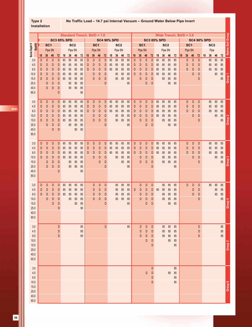
56
18 36 46 72 18 36 46 72 18 36 46 72 18 36 46 72 18 36 46 72 18 36 46 72 18 36 46 72 18 36 46 72 3.0 D D D D 85 85 85 85 D D D D 85 85 85 85 D D D D 85 85 85 85 D D D 85 85 85 4.5 D D D D 85 85 85 85 D D D D 85 85 85 85 D D D D 85 85 85 85 D D D 85 85 85 6.0 D D D D 85 85 85 85 D D D D 85 85 85 85 D D D D 85 85 85 85 D D D 85 85 85 10.0 D D D D 85 85 85 85 D D D 85 85 85 D D D D 85 85 85 85 D D 85 85 15.0 D D D D 85 85 85 85 D D D 85 85 85 D D D 85 85 85 D 85 25.0 D D D 85 85 85 D 85 D D 90 90 40.0 D D D 90 90 85 65.0 D 90 3.0 D D D D 85 85 85 85 D D D D 85 85 85 85 D D D D 85 85 85 85 D D D 85 85 85 4.5 D D D D 85 85 85 85 D D D D 85 85 85 85 D D D D 85 85 85 85 D D D 85 85 85 6.0 D D D D 85 85 85 85 D D D D 85 85 85 85 D D D D 85 85 85 85 D D D 85 85 85 10.0 D D D D 85 85 85 85 D D D 85 85 85 D D D D 85 85 85 85 D D 85 85 15.0 D D D D 85 85 85 85 D D D 85 85 85 D D D 85 85 85 D 85 25.0 D D D 85 85 85 D 85 D D 90 90 40.0 D D 90 90 65.0 3.0 D D D D 85 85 85 85 D D D D 85 85 85 85 D D D D 85 85 85 85 D D D 85 85 85 4.5 D D D D 85 85 85 85 D D D D 85 85 85 85 D D D D 85 85 85 85 D D D 85 85 85 6.0 D D D D 85 85 85 85 D D D D 85 85 85 85 D D D D 85 85 85 85 D D D 85 85 85 10.0 D D D D 85 85 85 85 D D D 85 85 85 D D D 85 85 85 D D 85 85 15.0 D D D 85 85 85 D D 85 85 D D D 85 85 85 D 85 25.0 D D D 90 85 85 D 90 D 90 40.0 D 90 65.0 3.0 D D D D 85 85 85 85 D D D 85 85 85 D D D 85 85 85 D D D 85 85 85 4.5 D D D D 85 85 85 85 D D D 85 85 85 D D D D 85 85 85 85 D D 85 85 6.0 D D D D 85 85 85 85 D D D 85 85 85 D D D 85 85 85 D D 85 85 10.0 D D D 85 85 85 D D D 85 85 85 D D D 85 85 85 D 85 15.0 D D 85 85 D 85 D D 85 85 25.0 D 90 40.0 65.0 3.0 D 85 D 85 D D D 85 85 85 D 85 4.5 D 85 D D D 85 85 85 D 85 6.0 D 85 D D D 85 85 85 D 85 10.0 D D 85 85 15.0 D 85 25.0 40.0 65.0
3.0 D 85 4.5 D D 85 85 6.0 D 85 10.0 D 85 15.0 25.0 40.0 65.0
Type 2 No Traffic Load – 14.7 psi Internal Vacuum – Ground Water Below Pipe InvertInstallation
Standard Trench, Bd/D = 1.8 Wide Trench, Bd/D = 3.0
Grou
p 6
Gro
up 5
Gro
up 4
Gro
up 3
Grou
p 2
Grou
p 1
Nat
ive S
oil G
roup
SC3 85% SPD SC4 90% SPD SC3 85% SPD SC4 90% SPDSC1 SC2 SC1 SC2 SC1 SC2 SC1 SC2Pipe SN Pipe SN Pipe SN Pipe SN Pipe SN Pipe SN Pipe SN Pipe
Buria
l Dep
th ft
Back
fill
app.

57
18 36 46 72 18 36 46 72 18 36 46 72 18 36 46 72 18 36 46 72 18 36 46 72 18 36 46 72 18 36 46 72 3.0 D D D D 85 85 85 85 D D D D 85 85 85 85 D D D D 85 85 85 85 D D D D 85 85 85 85 4.5 D D D D 85 85 85 85 D D D D 85 85 85 85 D D D D 85 85 85 85 D D D D 85 85 85 85 6.0 D D D D 85 85 85 85 D D D D 85 85 85 85 D D D D 85 85 85 85 D D D D 85 85 85 85 10.0 D D D D 85 85 85 85 D D D D 85 85 85 85 D D D D 85 85 85 85 D D D D 85 85 85 85 15.0 D D D D 85 85 85 85 D D D 85 85 85 D D D D 90 90 90 85 D D 90 90 25.0 D D D D 90 90 90 90 D D D 90 90 90 40.0 D 90 65.0 3.0 D D D D 85 85 85 85 D D D D 85 85 85 85 D D D D 85 85 85 85 D D D D 85 85 85 85 4.5 D D D D 85 85 85 85 D D D D 85 85 85 85 D D D D 85 85 85 85 D D D D 85 85 85 85 6.0 D D D D 85 85 85 85 D D D D 85 85 85 85 D D D D 85 85 85 85 D D D D 85 85 85 85 10.0 D D D D 85 85 85 85 D D D D 85 85 85 85 D D D D 85 85 85 85 D D D D 85 85 85 85 15.0 D D D D 85 85 85 85 D D D 85 85 85 D D D D 90 90 90 85 D D 90 90 25.0 D D D D 90 90 90 90 D D D 90 90 90 40.0 D 90 65.0 3.0 D D D D 85 85 85 85 D D D D 85 85 85 85 D D D D 85 85 85 85 D D D D 85 85 85 85 4.5 D D D D 85 85 85 85 D D D D 85 85 85 85 D D D D 85 85 85 85 D D D D 85 85 85 85 6.0 D D D D 85 85 85 85 D D D D 85 85 85 85 D D D D 85 85 85 85 D D D D 85 85 85 85 10.0 D D D D 85 85 85 85 D D D D 85 85 85 85 D D D D 85 85 85 85 D D D D 85 85 85 85 15.0 D D D D 85 85 85 85 D D D 85 85 85 D D D D 90 90 90 85 D D 90 90 25.0 D D D 90 90 90 D D 90 90 40.0 C 95 65.0 3.0 D D D D 85 85 85 85 D D D D 85 85 85 85 D D D D 85 85 85 85 D D D D 85 85 85 85 4.5 D D D D 85 85 85 85 D D D D 85 85 85 85 D D D D 85 85 85 85 D D D D 85 85 85 85 6.0 D D D D 85 85 85 85 D D D D 85 85 85 85 D D D D 85 85 85 85 D D D D 85 85 85 85 10.0 D D D D 85 85 85 85 D D D D 85 85 85 85 D D D D 85 85 85 85 D D D D 85 85 85 85 15.0 D D D D 90 90 90 85 D D D 90 90 90 D D D D 90 90 90 90 D 90 25.0 C C 95 95 D 90 40.0 65.0
3.0 D D D D 85 85 85 85 D D D D 85 85 85 85 D D D D 85 85 85 85 D D D D 85 85 85 85 4.5 D D D D 85 85 85 85 D D D D 85 85 85 85 D D D D 85 85 85 85 D D D D 85 85 85 85 6.0 D D D D 85 85 85 85 D D D D 85 85 85 85 D D D D 85 85 85 85 D D D D 85 85 85 85 10.0 D D D D 90 90 90 85 D D D D 90 90 90 85 D D D D 85 85 85 85 D D D 90 90 85 15.0 C C 95 95 D D D 90 90 90 25.0 40.0 65.0
3.0 D D D D 85 85 85 85 D D D D 85 85 85 85 D D D D 85 85 85 85 D D D D 85 85 85 85 4.5 D D D D 90 85 85 85 D D D D 90 85 85 85 D D D D 85 85 85 85 D D D D 85 85 85 85 6.0 C D D D 95 90 90 85 D D D 90 90 85 D D D D 85 85 85 85 D D D D 90 85 85 85 10.0 C D 95 95 D D D D 90 90 90 85 D D D 90 90 85 15.0 D D 90 90 25.0 40.0 65.0
Type 2 No Traffic Load – No Internal Vacuum – Ground Water to Grade LevelInstallation
Grou
p 6
Gro
up 5
Gro
up 4
Gro
up 3
Grou
p 2
Grou
p 1
Nat
ive S
oil G
roup
Table B–12 No Traffic Load – No Internal Vacuum – Ground Water to Grade LevelMinimum Backfill Compaction, % Standard Proctor Density. (D=Dumped, C= Compacted)
SC3 85% SPD SC4 95% SPD SC3 85% SPD SC4 95% SPDSC1 SC2 SC1 SC2 SC1 SC2 SC1 SC2Pipe SN Pipe SN Pipe SN Pipe SN Pipe SN Pipe SN Pipe SN Pipe
Buria
l Dep
th ft
UpperBackfill
Back
fill
app.
57

58
18 36 46 72 18 36 46 72 18 36 46 72 18 36 46 72 18 36 46 72 18 36 46 72 18 36 46 72 18 36 46 72
Type 2 No Traffic Load – 7.35 psi Internal Vacuum – Ground Water to Grade LevelInstallation
Standard Trench, Bd/D = 1.8 Wide Trench, Bd/D = 3.0
Grou
p 6
Gro
up 5
Gro
up 4
Gro
up 3
Grou
p 2
Grou
p 1
Nat
ive S
oil G
roup
Table B–13 No Traffic Load – 7.35 psi Internal Vacuum – Ground Water to Grade LevelMinimum Backfill Compaction, % Standard Proctor Density. (D=Dumped, C= Compacted)
SC3 85% SPD SC4 95% SPD SC3 85% SPD SC4 95% SPDSC1 SC2 SC1 SC2 SC1 SC2 SC1 SC2Pipe SN Pipe SN Pipe SN Pipe SN Pipe SN Pipe SN Pipe SN Pipe
Buria
l Dep
th ft
UpperBackfill
Back
fill
app.
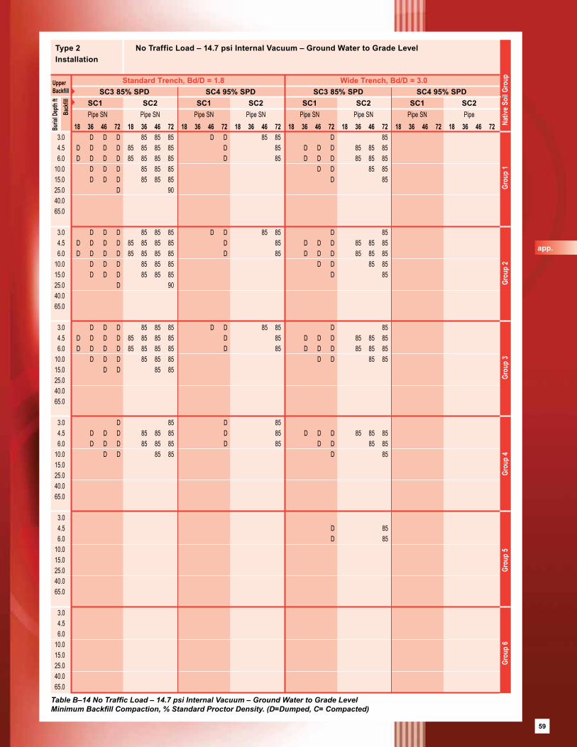
59
18 36 46 72 18 36 46 72 18 36 46 72 18 36 46 72 18 36 46 72 18 36 46 72 18 36 46 72 18 36 46 72 3.0 D D D 85 85 85 D D 85 85 D 85 4.5 D D D D 85 85 85 85 D 85 D D D 85 85 85 6.0 D D D D 85 85 85 85 D 85 D D D 85 85 85 10.0 D D D 85 85 85 D D 85 85 15.0 D D D 85 85 85 D 85 25.0 D 90 40.0 65.0
3.0 D D D 85 85 85 D D 85 85 D 85 4.5 D D D D 85 85 85 85 D 85 D D D 85 85 85 6.0 D D D D 85 85 85 85 D 85 D D D 85 85 85 10.0 D D D 85 85 85 D D 85 85 15.0 D D D 85 85 85 D 85 25.0 D 90 40.0 65.0
3.0 D D D 85 85 85 D D 85 85 D 85 4.5 D D D D 85 85 85 85 D 85 D D D 85 85 85 6.0 D D D D 85 85 85 85 D 85 D D D 85 85 85 10.0 D D D 85 85 85 D D 85 85 15.0 D D 85 85 25.0 40.0 65.0
3.0 D 85 D 85 4.5 D D D 85 85 85 D 85 D D D 85 85 85 6.0 D D D 85 85 85 D 85 D D 85 85 10.0 D D 85 85 D 85 15.0 25.0 40.0 65.0
3.0 4.5 D 85 6.0 D 85 10.0 15.0 25.0 40.0 65.0
3.0 4.5 6.0 10.0 15.0 25.0 40.0 65.0
Type 2 No Traffic Load – 14.7 psi Internal Vacuum – Ground Water to Grade LevelInstallation
Standard Trench, Bd/D = 1.8 Wide Trench, Bd/D = 3.0
Grou
p 6
Gro
up 5
Gro
up 4
Gro
up 3
Grou
p 2
Grou
p 1
Nat
ive S
oil G
roup
Table B–14 No Traffic Load – 14.7 psi Internal Vacuum – Ground Water to Grade LevelMinimum Backfill Compaction, % Standard Proctor Density. (D=Dumped, C= Compacted)
SC3 85% SPD SC4 95% SPD SC3 85% SPD SC4 95% SPDSC1 SC2 SC1 SC2 SC1 SC2 SC1 SC2Pipe SN Pipe SN Pipe SN Pipe SN Pipe SN Pipe SN Pipe SN Pipe
Buria
l Dep
th ft
UpperBackfill
Back
fill
app.
59
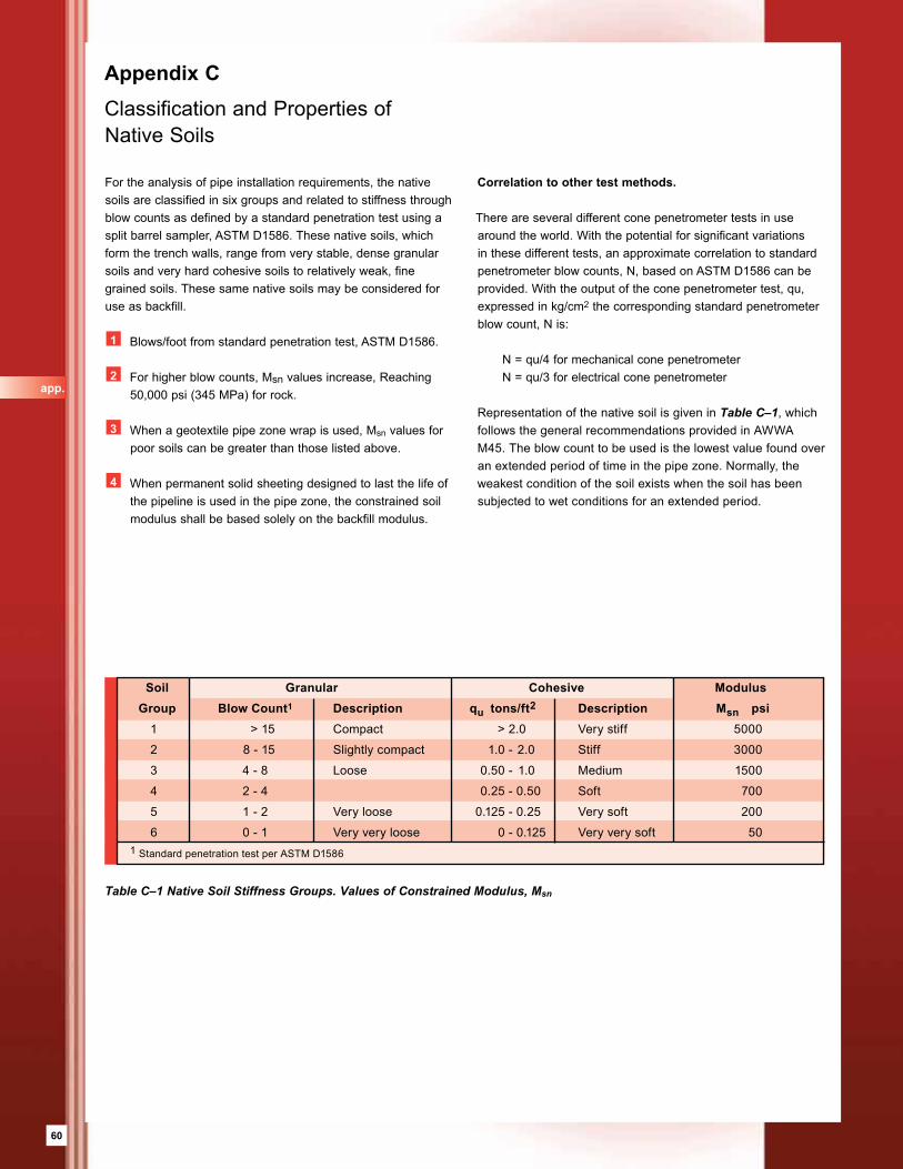
60
Appendix C Classification and Properties of Native Soils
For the analysis of pipe installation requirements, the native soils are classified in six groups and related to stiffness through blow counts as defined by a standard penetration test using a split barrel sampler, ASTM D1586. These native soils, which form the trench walls, range from very stable, dense granular soils and very hard cohesive soils to relatively weak, fine grained soils. These same native soils may be considered for use as backfill.
1 Blows/foot from standard penetration test, ASTM D1586.
2 For higher blow counts, Msn values increase, Reaching 50,000 psi (345 MPa) for rock.
3 When a geotextile pipe zone wrap is used, Msn values for poor soils can be greater than those listed above.
4 When permanent solid sheeting designed to last the life of the pipeline is used in the pipe zone, the constrained soil modulus shall be based solely on the backfill modulus.
Correlation to other test methods.
There are several different cone penetrometer tests in use around the world. With the potential for significant variations in these different tests, an approximate correlation to standard penetrometer blow counts, N, based on ASTM D1586 can be provided. With the output of the cone penetrometer test, qu, expressed in kg/cm2 the corresponding standard penetrometer blow count, N is: N = qu/4 for mechanical cone penetrometer N = qu/3 for electrical cone penetrometer
Representation of the native soil is given in Table C–1, which follows the general recommendations provided in AWWA M45. The blow count to be used is the lowest value found over an extended period of time in the pipe zone. Normally, the weakest condition of the soil exists when the soil has been subjected to wet conditions for an extended period.
Table C–1 Native Soil Stiffness Groups. Values of Constrained Modulus, Msn
Soil Granular Cohesive Modulus Group Blow Count1 Description qu tons/ft2 Description Msn psi 1 > 15 Compact > 2.0 Very stiff 5000
2 8 - 15 Slightly compact 1.0 - 2.0 Stiff 3000
3 4 - 8 Loose 0.50 - 1.0 Medium 1500
4 2 - 4 0.25 - 0.50 Soft 700
5 1 - 2 Very loose 0.125 - 0.25 Very soft 200
6 0 - 1 Very very loose 0 - 0.125 Very very soft 501 Standard penetration test per ASTM D1586
app.
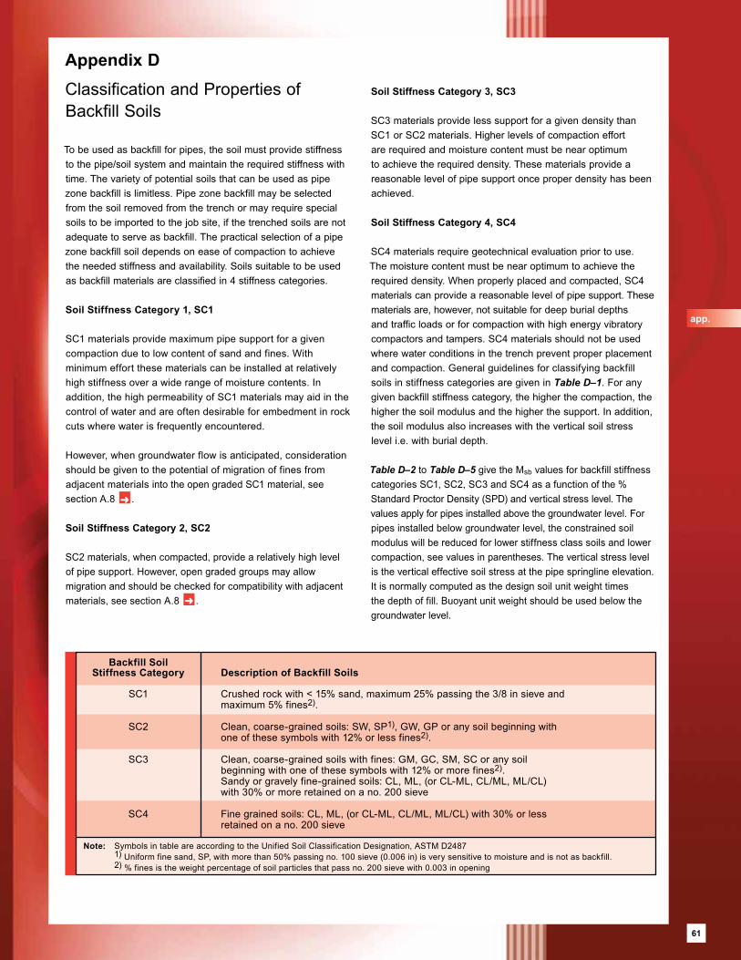
61
Appendix D Classification and Properties of Backfill Soils
To be used as backfill for pipes, the soil must provide stiffness to the pipe/soil system and maintain the required stiffness with time. The variety of potential soils that can be used as pipe zone backfill is limitless. Pipe zone backfill may be selected from the soil removed from the trench or may require special soils to be imported to the job site, if the trenched soils are not adequate to serve as backfill. The practical selection of a pipe zone backfill soil depends on ease of compaction to achieve the needed stiffness and availability. Soils suitable to be used as backfill materials are classified in 4 stiffness categories.
Soil Stiffness Category 1, SC1
SC1 materials provide maximum pipe support for a given compaction due to low content of sand and fines. With minimum effort these materials can be installed at relatively high stiffness over a wide range of moisture contents. In addition, the high permeability of SC1 materials may aid in the control of water and are often desirable for embedment in rock cuts where water is frequently encountered.
However, when groundwater flow is anticipated, consideration should be given to the potential of migration of fines from adjacent materials into the open graded SC1 material, see section A.8 ➜ .
Soil Stiffness Category 2, SC2
SC2 materials, when compacted, provide a relatively high level of pipe support. However, open graded groups may allow migration and should be checked for compatibility with adjacent materials, see section A.8 ➜ .
Soil Stiffness Category 3, SC3
SC3 materials provide less support for a given density than SC1 or SC2 materials. Higher levels of compaction effort are required and moisture content must be near optimum to achieve the required density. These materials provide a reasonable level of pipe support once proper density has been achieved.
Soil Stiffness Category 4, SC4
SC4 materials require geotechnical evaluation prior to use. The moisture content must be near optimum to achieve the required density. When properly placed and compacted, SC4 materials can provide a reasonable level of pipe support. These materials are, however, not suitable for deep burial depths and traffic loads or for compaction with high energy vibratory compactors and tampers. SC4 materials should not be used where water conditions in the trench prevent proper placement and compaction. General guidelines for classifying backfill soils in stiffness categories are given in Table D–1. For any given backfill stiffness category, the higher the compaction, the higher the soil modulus and the higher the support. In addition, the soil modulus also increases with the vertical soil stress level i.e. with burial depth.
Table D–2 to Table D–5 give the Msb values for backfill stiffness categories SC1, SC2, SC3 and SC4 as a function of the % Standard Proctor Density (SPD) and vertical stress level. The values apply for pipes installed above the ground water level. For pipes installed below groundwater level, the constrained soil modulus will be reduced for lower stiffness class soils and lower compaction, see values in parentheses. The vertical stress level is the vertical effective soil stress at the pipe springline elevation. It is normally computed as the design soil unit weight times the depth of fill. Buoyant unit weight should be used below the groundwater level.
Backfill Soil Stiffness Category Description of Backfill Soils
SC1 Crushed rock with < 15% sand, maximum 25% passing the 3/8 in sieve and maximum 5% fines2).
SC2 Clean, coarse-grained soils: SW, SP1), GW, GP or any soil beginning with one of these symbols with 12% or less fines2).
SC3 Clean, coarse-grained soils with fines: GM, GC, SM, SC or any soil beginning with one of these symbols with 12% or more fines2). Sandy or gravely fine-grained soils: CL, ML, (or CL-ML, CL/ML, ML/CL) with 30% or more retained on a no. 200 sieve
SC4 Fine grained soils: CL, ML, (or CL-ML, CL/ML, ML/CL) with 30% or less retained on a no. 200 sieve
Note: Symbols in table are according to the Unified Soil Classification Designation, ASTM D2487 1) Uniform fine sand, SP, with more than 50% passing no. 100 sieve (0.006 in) is very sensitive to moisture and is not as backfill. 2) % fines is the weight percentage of soil particles that pass no. 200 sieve with 0.003 in opening
app.
61
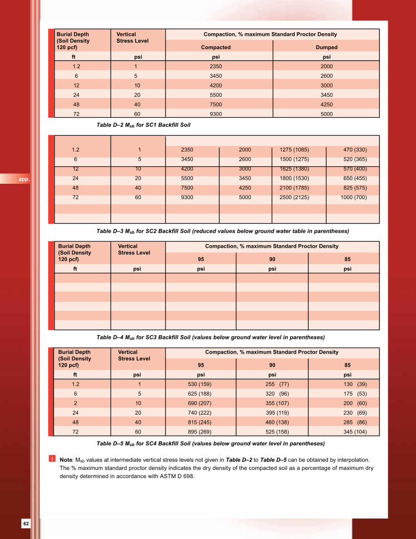
62
Table D–2 Msb for SC1 Backfill Soil
Table D–3 Msb for SC2 Backfill Soil (reduced values below ground water table in parentheses)
Table D–4 Msb for SC3 Backfill Soil (values below ground water level in parentheses)
Table D–5 Msb for SC4 Backfill Soil (values below ground water level in parentheses)
! Note: Msb values at intermediate vertical stress levels not given in Table D–2 to Table D–5 can be obtained by interpolation. The % maximum standard proctor density indicates the dry density of the compacted soil as a percentage of maximum dry density determined in accordance with ASTM D 698.
Burial Depth Vertical Compaction, % maximum Standard Proctor Density(Soil Density Stress Level 120 pcf) Compacted Dumped
ft psi psi psi
1.2 1 2350 2000
6 5 3450 2600
12 10 4200 3000
24 20 5500 3450
48 40 7500 4250
72 60 9300 5000
1.2 1 2350 2000 1275 (1085) 470 (330)
6 5 3450 2600 1500 (1275) 520 (365)
12 10 4200 3000 1625 (1380) 570 (400)
24 20 5500 3450 1800 (1530) 650 (455)
48 40 7500 4250 2100 (1785) 825 (575)
72 60 9300 5000 2500 (2125) 1000 (700)
Burial Depth Vertical Compaction, % maximum Standard Proctor Density(Soil Density Stress Level 120 pcf) 95 90 85
ft psi psi psi psi
Burial Depth Vertical Compaction, % maximum Standard Proctor Density(Soil Density Stress Level 120 pcf) 95 90 85
ft psi psi psi psi
1.2 1 530 (159) 255 (77) 130 (39)
6 5 625 (188) 320 (96) 175 (53)
2 10 690 (207) 355 (107) 200 (60)
24 20 740 (222) 395 (119) 230 (69)
48 40 815 (245) 460 (138) 285 (86)
72 60 895 (269) 525 (158) 345 (104)
app.
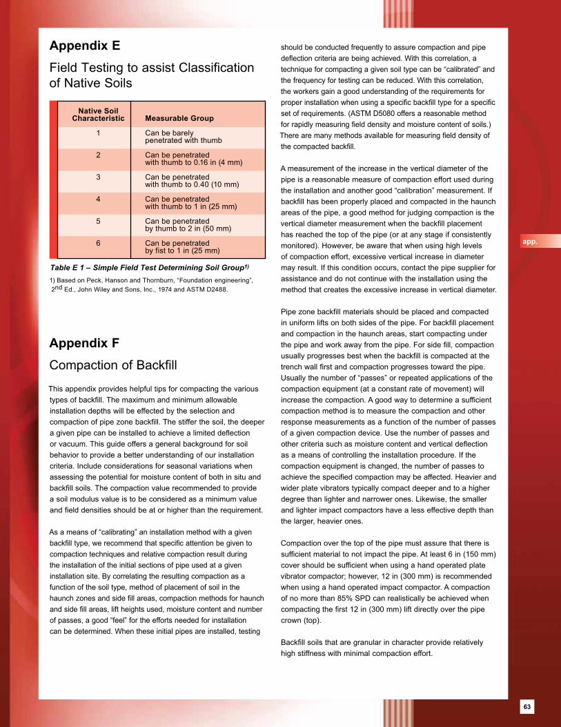
63
Table E 1 – Simple Field Test Determining Soil Group1)
Appendix E Field Testing to assist Classification of Native Soils
Native Soil Characteristic Measurable Group
1 Can be barely penetrated with thumb
2 Can be penetrated with thumb to 0.16 in (4 mm)
3 Can be penetrated with thumb to 0.40 (10 mm)
4 Can be penetrated with thumb to 1 in (25 mm)
5 Can be penetrated by thumb to 2 in (50 mm)
6 Can be penetrated by fist to 1 in (25 mm)
Appendix F
Compaction of Backfill
This appendix provides helpful tips for compacting the various types of backfill. The maximum and minimum allowable installation depths will be effected by the selection and compaction of pipe zone backfill. The stiffer the soil, the deeper a given pipe can be installed to achieve a limited deflection or vacuum. This guide offers a general background for soil behavior to provide a better understanding of our installation criteria. Include considerations for seasonal variations when assessing the potential for moisture content of both in situ and backfill soils. The compaction value recommended to provide a soil modulus value is to be considered as a minimum value and field densities should be at or higher than the requirement.
As a means of “calibrating” an installation method with a given backfill type, we recommend that specific attention be given to compaction techniques and relative compaction result during the installation of the initial sections of pipe used at a given installation site. By correlating the resulting compaction as a function of the soil type, method of placement of soil in the haunch zones and side fill areas, compaction methods for haunch and side fill areas, lift heights used, moisture content and number of passes, a good “feel” for the efforts needed for installation can be determined. When these initial pipes are installed, testing
should be conducted frequently to assure compaction and pipe deflection criteria are being achieved. With this correlation, a technique for compacting a given soil type can be “calibrated” and the frequency for testing can be reduced. With this correlation, the workers gain a good understanding of the requirements for proper installation when using a specific backfill type for a specific set of requirements. (ASTM D5080 offers a reasonable method for rapidly measuring field density and moisture content of soils.) There are many methods available for measuring field density of the compacted backfill.
A measurement of the increase in the vertical diameter of the pipe is a reasonable measure of compaction effort used during the installation and another good “calibration” measurement. If backfill has been properly placed and compacted in the haunch areas of the pipe, a good method for judging compaction is the vertical diameter measurement when the backfill placement has reached the top of the pipe (or at any stage if consistently monitored). However, be aware that when using high levels of compaction effort, excessive vertical increase in diameter may result. If this condition occurs, contact the pipe supplier for assistance and do not continue with the installation using the method that creates the excessive increase in vertical diameter.
Pipe zone backfill materials should be placed and compacted in uniform lifts on both sides of the pipe. For backfill placement and compaction in the haunch areas, start compacting under the pipe and work away from the pipe. For side fill, compaction usually progresses best when the backfill is compacted at the trench wall first and compaction progresses toward the pipe. Usually the number of “passes” or repeated applications of the compaction equipment (at a constant rate of movement) will increase the compaction. A good way to determine a sufficient compaction method is to measure the compaction and other response measurements as a function of the number of passes of a given compaction device. Use the number of passes and other criteria such as moisture content and vertical deflection as a means of controlling the installation procedure. If the compaction equipment is changed, the number of passes to achieve the specified compaction may be affected. Heavier and wider plate vibrators typically compact deeper and to a higher degree than lighter and narrower ones. Likewise, the smaller and lighter impact compactors have a less effective depth than the larger, heavier ones.
Compaction over the top of the pipe must assure that there is sufficient material to not impact the pipe. At least 6 in (150 mm) cover should be sufficient when using a hand operated plate vibrator compactor; however, 12 in (300 mm) is recommended when using a hand operated impact compactor. A compaction of no more than 85% SPD can realistically be achieved when compacting the first 12 in (300 mm) lift directly over the pipe crown (top).
Backfill soils that are granular in character provide relatively high stiffness with minimal compaction effort.
1) Based on Peck, Hanson and Thornburn, “Foundation engineering”, 2nd Ed., John Wiley and Sons, Inc., 1974 and ASTM D2488.
app.
63
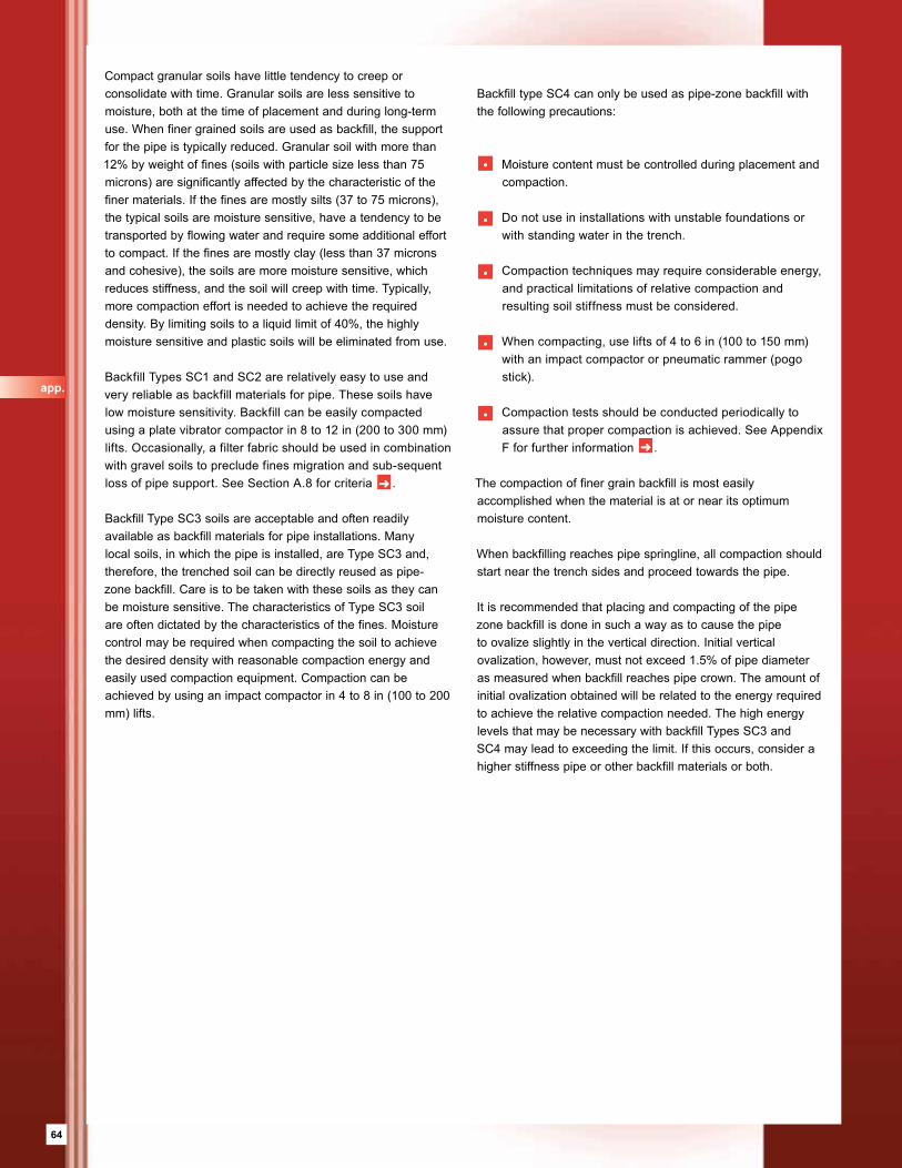
64
Compact granular soils have little tendency to creep or consolidate with time. Granular soils are less sensitive to moisture, both at the time of placement and during long-term use. When finer grained soils are used as backfill, the support for the pipe is typically reduced. Granular soil with more than 12% by weight of fines (soils with particle size less than 75 microns) are significantly affected by the characteristic of the finer materials. If the fines are mostly silts (37 to 75 microns), the typical soils are moisture sensitive, have a tendency to be transported by flowing water and require some additional effort to compact. If the fines are mostly clay (less than 37 microns and cohesive), the soils are more moisture sensitive, which reduces stiffness, and the soil will creep with time. Typically, more compaction effort is needed to achieve the required density. By limiting soils to a liquid limit of 40%, the highly moisture sensitive and plastic soils will be eliminated from use.
Backfill Types SC1 and SC2 are relatively easy to use and very reliable as backfill materials for pipe. These soils have low moisture sensitivity. Backfill can be easily compacted using a plate vibrator compactor in 8 to 12 in (200 to 300 mm) lifts. Occasionally, a filter fabric should be used in combination with gravel soils to preclude fines migration and sub-sequent loss of pipe support. See Section A.8 for criteria ➜ .
Backfill Type SC3 soils are acceptable and often readily available as backfill materials for pipe installations. Many local soils, in which the pipe is installed, are Type SC3 and, therefore, the trenched soil can be directly reused as pipe-zone backfill. Care is to be taken with these soils as they can be moisture sensitive. The characteristics of Type SC3 soil are often dictated by the characteristics of the fines. Moisture control may be required when compacting the soil to achieve the desired density with reasonable compaction energy and easily used compaction equipment. Compaction can be achieved by using an impact compactor in 4 to 8 in (100 to 200 mm) lifts.
Backfill type SC4 can only be used as pipe-zone backfill with the following precautions:
• Moisture content must be controlled during placement and compaction.
• Do not use in installations with unstable foundations or with standing water in the trench.
• Compaction techniques may require considerable energy, and practical limitations of relative compaction and resulting soil stiffness must be considered.
• When compacting, use lifts of 4 to 6 in (100 to 150 mm) with an impact compactor or pneumatic rammer (pogo stick).
• Compaction tests should be conducted periodically to assure that proper compaction is achieved. See Appendix F for further information ➜ .
The compaction of finer grain backfill is most easily accomplished when the material is at or near its optimum moisture content.
When backfilling reaches pipe springline, all compaction should start near the trench sides and proceed towards the pipe.
It is recommended that placing and compacting of the pipe zone backfill is done in such a way as to cause the pipe to ovalize slightly in the vertical direction. Initial vertical ovalization, however, must not exceed 1.5% of pipe diameter as measured when backfill reaches pipe crown. The amount of initial ovalization obtained will be related to the energy required to achieve the relative compaction needed. The high energy levels that may be necessary with backfill Types SC3 and SC4 may lead to exceeding the limit. If this occurs, consider a higher stiffness pipe or other backfill materials or both.
app.

65
Appendix G
Definitions and Terminology
Term Description
Nominal diameter, DN The diameter classification of pipe, expressed in inches (mm).
Nominal Pressure, PN The pressure rating of a pipe, expressed in psi (bar).
Nominal Stiffness, SN The minimum initial specific stiffness, El/D3, of a pipe as measured by a load required to deflect a pipe ring, expressed in psi (N/m2).
Pipe crown The top inside surface of the pipe.
Pipe invert The bottom inside surface of a pipe.
Depth of bury The depth of cover over the top of a pipe.
Deflection The change in vertical diameter typically expressed as a percentage of the nominal pipe diameter.
Springline The mid-height of the pipe, the 90 and 270 degree locations of a pipe as measured from the top center of the pipe.
Constrained soil modulus, Ms A secant modulus of soil measured by a one dimensional compression test used to describe soil stiffness.
Standard Proctor Density, SPD The maximum dry density obtained at optimum moisture content when tested by ASTM D698, used to define 100% standard proctor density.
Percent Standard The achieved dry density/maximum dry density expressed in %.Proctor Density
Blow Counts The number of impacts of a 140 pound (64 kg) hammer dropping 30 inches (76 cm) to drive a split barrel sampler 12 inches (300 mm) by ASTM D1586.
app.
Appendix H Approximate Weights for Pipes and Couplings
DN SN18 SN36 SN46 SN72 Couplingin lbs/ft* lbs/ft* lbs/ft* lbs/ft* lbs/ft**12 6 8 8 9 716 10 13 14 16 818 13 17 18 19 920 17 21 22 25 1024 24 30 32 37 1730 37 45 49 56 2536 52 64 70 80 2842 70 87 93 108 3448 91 113 127 141 4154 115 145 156 180 5360 133 165 179 206 5963 145 181 196 226 6472 183 229 247 284 7578 225 281 304 350 8784 272 340 367 424 9896 324 403 437 503 109
* Based on PN 50 which is the heaviest pipe ** Based on PN 250 which is the heaviest coupling
65
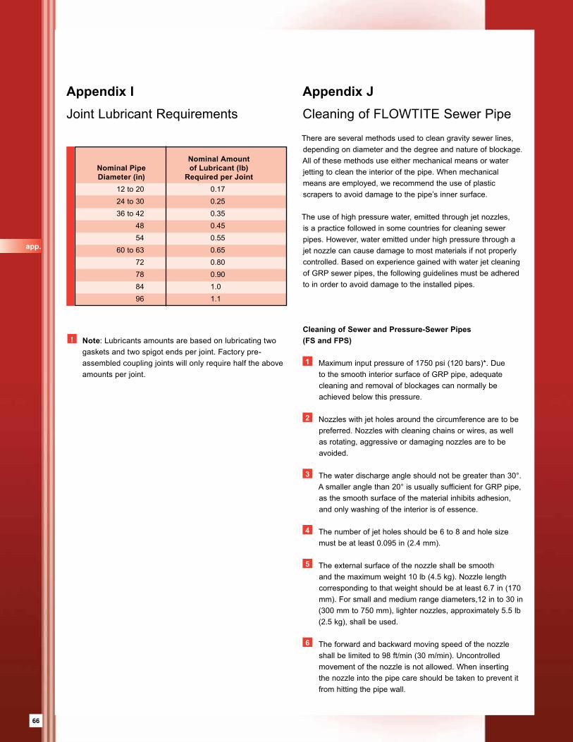
66
app.
Appendix I Joint Lubricant Requirements
Nominal Amount Nominal Pipe of Lubricant (lb) Diameter (in) Required per Joint 12 to 20 0.17 24 to 30 0.25 36 to 42 0.35 48 0.45 54 0.55 60 to 63 0.65 72 0.80 78 0.90 84 1.0 96 1.1
There are several methods used to clean gravity sewer lines, depending on diameter and the degree and nature of blockage. All of these methods use either mechanical means or water jetting to clean the interior of the pipe. When mechanical means are employed, we recommend the use of plastic scrapers to avoid damage to the pipe’s inner surface.
The use of high pressure water, emitted through jet nozzles, is a practice followed in some countries for cleaning sewer pipes. However, water emitted under high pressure through a jet nozzle can cause damage to most materials if not properly controlled. Based on experience gained with water jet cleaning of GRP sewer pipes, the following guidelines must be adhered to in order to avoid damage to the installed pipes.
Cleaning of Sewer and Pressure-Sewer Pipes (FS and FPS)
1 Maximum input pressure of 1750 psi (120 bars)*. Due to the smooth interior surface of GRP pipe, adequate cleaning and removal of blockages can normally be achieved below this pressure.
2 Nozzles with jet holes around the circumference are to be preferred. Nozzles with cleaning chains or wires, as well as rotating, aggressive or damaging nozzles are to be avoided.
3 The water discharge angle should not be greater than 30°. A smaller angle than 20° is usually sufficient for GRP pipe, as the smooth surface of the material inhibits adhesion, and only washing of the interior is of essence.
4 The number of jet holes should be 6 to 8 and hole size must be at least 0.095 in (2.4 mm).
5 The external surface of the nozzle shall be smooth and the maximum weight 10 lb (4.5 kg). Nozzle length corresponding to that weight should be at least 6.7 in (170 mm). For small and medium range diameters,12 in to 30 in (300 mm to 750 mm), lighter nozzles, approximately 5.5 lb (2.5 kg), shall be used.
6 The forward and backward moving speed of the nozzle shall be limited to 98 ft/min (30 m/min). Uncontrolled movement of the nozzle is not allowed. When inserting the nozzle into the pipe care should be taken to prevent it from hitting the pipe wall.
Appendix JCleaning of FLOWTITE Sewer Pipe
! Note: Lubricants amounts are based on lubricating two gaskets and two spigot ends per joint. Factory pre-assembled coupling joints will only require half the above amounts per joint.
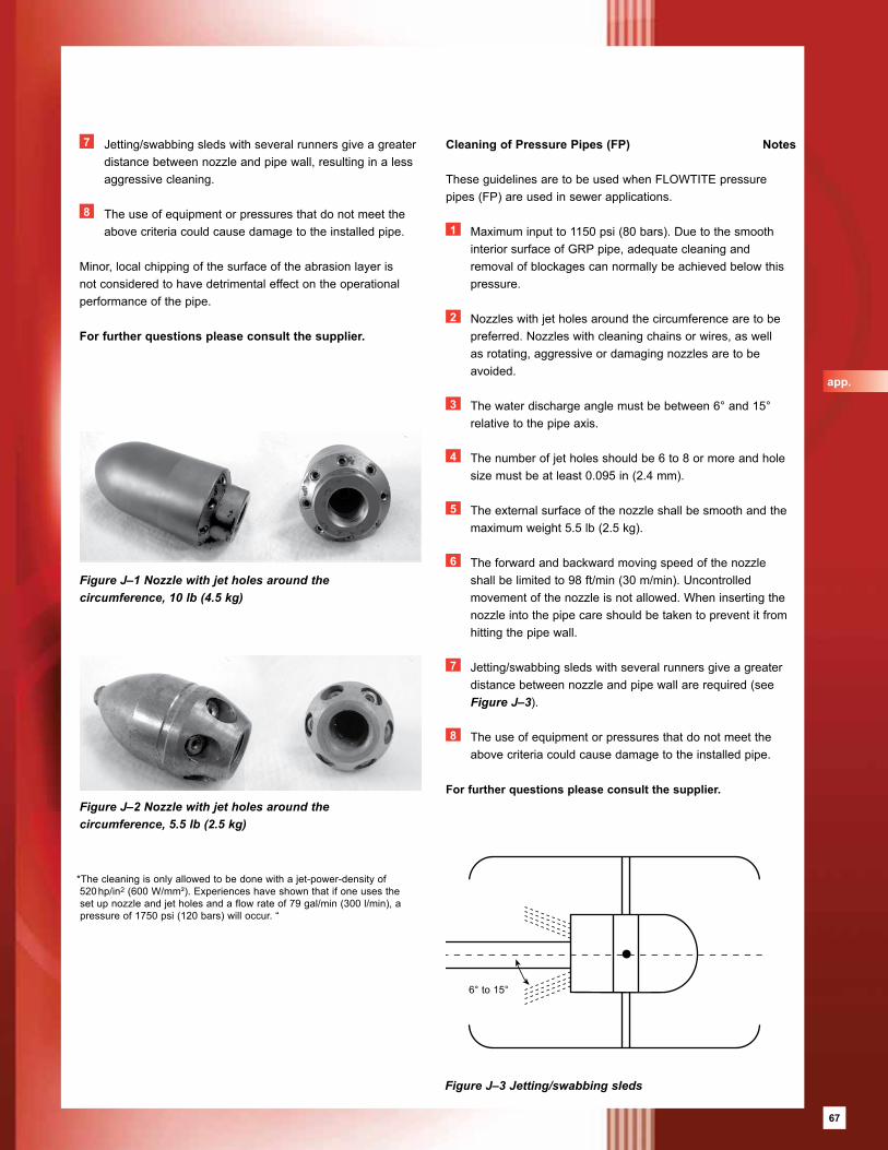
67
app.
Cleaning of Pressure Pipes (FP)
These guidelines are to be used when FLOWTITE pressure pipes (FP) are used in sewer applications.
1 Maximum input to 1150 psi (80 bars). Due to the smooth interior surface of GRP pipe, adequate cleaning and removal of blockages can normally be achieved below this pressure.
2 Nozzles with jet holes around the circumference are to be preferred. Nozzles with cleaning chains or wires, as well as rotating, aggressive or damaging nozzles are to be avoided.
3 The water discharge angle must be between 6° and 15° relative to the pipe axis.
4 The number of jet holes should be 6 to 8 or more and hole size must be at least 0.095 in (2.4 mm).
5 The external surface of the nozzle shall be smooth and the maximum weight 5.5 lb (2.5 kg).
6 The forward and backward moving speed of the nozzle shall be limited to 98 ft/min (30 m/min). Uncontrolled movement of the nozzle is not allowed. When inserting the nozzle into the pipe care should be taken to prevent it from hitting the pipe wall.
7 Jetting/swabbing sleds with several runners give a greater distance between nozzle and pipe wall are required (see Figure J–3).
8 The use of equipment or pressures that do not meet the above criteria could cause damage to the installed pipe.
For further questions please consult the supplier.
6° to 15°
Figure J–3 Jetting/swabbing sleds
7 Jetting/swabbing sleds with several runners give a greater distance between nozzle and pipe wall, resulting in a less aggressive cleaning.
8 The use of equipment or pressures that do not meet the above criteria could cause damage to the installed pipe.
Minor, local chipping of the surface of the abrasion layer is not considered to have detrimental effect on the operational performance of the pipe.
For further questions please consult the supplier.
*The cleaning is only allowed to be done with a jet-power-density of 520 hp/in2 (600 W/mm²). Experiences have shown that if one uses the set up nozzle and jet holes and a flow rate of 79 gal/min (300 l/min), a pressure of 1750 psi (120 bars) will occur. “
Figure J–2 Nozzle with jet holes around the circumference, 5.5 lb (2.5 kg)
Figure J–1 Nozzle with jet holes around the circumference, 10 lb (4.5 kg)
Notes
67

68
app.

69
app.
69

Notes

This Installation Guide for Buried Pipe is the intellectual property of FTEC. All rights reserved.
No part of this Installation Guide may be reproduced, stored in a retrieval system, or transmitted in any form or by any means, electronic, mechanical, photocopying, recording or otherwise without the prior permission of the intellectual property owner.
Profiles for Fillings
Bedding / Foundationcompacted
Bedding / Foundation
Backfill
Backfill compacted
Concrete
Wood
Stone

Although the utmost care has been taken to ensure the accuracy of
the contents of this brochure, US Composite Pipe South does not
accept liability for errors or omissions in this publication.
Customers must satisfy themselves of the suitability of a given
product supplied or manufactured by US Composite Pipe South.
w w w . f l o w t i t e p i p e . c o m
18585 Samuels Rd. Zachary, La. 70791PH. 225-658-6166 Fax 225-658-0947
U.S. COMPOSITE PIPE SOUTH, LLC.
2010 Revision 1MEMBER OF KTI PIPE GROUP OF COMPANIES