Embed Size (px)
Citation preview

FloWingEccentric Rotary type
Control ValvesModel: VFR (3, 4 inches)
User’s Manual
OM2-8130-01007th edition

Copyright, Notices and Trademarks
© 2012 Azbil Corporation All Rights Reserved.While this information is presented in good faith and believed tobe accurate, Azbil Corporation disclaims the implied warrantiesof merchantability and fitness for a particular purpose and makesno express warranties except as may be stated in its writtenagreement with and for its customer.
In no event is Azbil Corporation liable to anyone for any indirect,special or consequential damages. This information and specifi-cations in this document are subject to change without notice.

i
Safety Guide
1 : Nomenclature of partsDiagrams with the control valve terminologies and words used in this manual are shown below. Please familiarise yourself with these definitions before using the device.
Figure S-1 Nomenclature of globe valve
Figure S-2 Nomenclature of butterfly valve
Diaphragm
Yoke
Bonnet
Valve body
Flange
Actuator
Body
Valve body(Vane or disk)
Link
Actuator

Safety Guide Azbil Corporation
ii
2 : Safety precautionsPlease read this section before using the valve to ensure proper handling.
� WARNING
If the stated procedures are not followed as specified, a potentially hazardous situation may arise, which could result in death or serious injury.
� CAUTION
Failure to observe these cautions may create dangerous conditions that could result in injury to the personnel and/or in physical damage to the device.
3 : Verification of Valve Specifications and Precautions on Storage
3-1 UnpackingControl valve is a precision equipment. Handle it with care to avoid damaging it.
When unpacking, check that the following items are in the crate:
• Main valve body, actuator and accessories as ordered,• Additional equipment as ordered. Installation options
3-2 Verification of specificationsPlease check and see if that the process flow fluid conditions, and valve Tag No. agree with the specifications that were ordered. The nameplate of each product are found as shown below. (Other products have their nameplates attached to the identical posi-tions.)

Azbil Corporation Safety Guide
iii
Figure S-3 Position of nameplate on NEW10-II Series
Figure S-4 Position of name plate on CV3000 Alphaplus Series
Figure S-5 Position of nameplate on CV3000 Series

Safety Guide Azbil Corporation
iv
� Cautions on storage
When storing the control valve, pay attention to the following precautions:• A control valve that has been packed in a cardboard box should be stored indoors
at normal temperature and humidity.• A control valve that has been packed in a wooden crate should be stored indoors at
normal temperature and humidity as a rule. In the event outdoor storage, open the crate, verify the specifications of the unit and cover it with a polyethylene protec-tive sheet to guard against precipitation.
• When storing a used valve, follow the procedures described below:(1) Flush out the process fluid from inside the valve body and dry,
(2) When there is a possibility of the valve body rusting, preservation treatment should be given,
(3) To prevent water from getting into the instrument, cover pneumatic tubing con-nection and electric connector with watertight caps or tape. Also, protect the connector threads,
(4) Place a flange cap onto the end of the pipe connecting surface (flange face, butt welding connections) to avoid any possible damage.

Azbil Corporation Safety Guide
v
4 : Installation
4-1 Installation environments
� CAUTION
• Ensure sufficient space for easy and safe operation and maintenance of the control valve.
• Avoid installing the valve in a loca-tion where vibration or external stress may impair proper valve functions. If necessary, make appropriate provisions against these.
• Consider providing a support for the valve, so that the process piping is not burdened with the excessive weight of valve, or provide sup-ports on the upstream and down-stream pipe runs.
• Provide a cover or protective fence around the valve installation, when a valve is installed facing a path or if physical contact with valve is expected.
• Do not install a valve where it is submerged under the water, or snow or freezing may take place.
• Provide a wall for protection against heat radiation. • Provide measures to protect the valve against salt spray or corrosive atmosphere. • To stop operation of the Flowmeter:
- Switch the control equipment connected to the flowmeter to manual control.- To turn the power to the converter off.
� CAUTION
• In order to guard against accident while handling the valve, always wear safety gloves, goggles and safety shoes.
Pipe support
Maintenance space

Safety Guide Azbil Corporation
vi
Prior to installation work, follow the items of caution as described below:
� CAUTION
• Check and confirm that there is no external damage to the valve (body, actuator, accessories).
• Check and confirm that there is no damage on pipe connecting flanges or butt welding connections.
• Ensure that the temperature of welded part of pipe has been reduced before proceeding.
• Make sure that the flanges on pipe have been chamfered.
• Remove dust, sand, welding spatter or any other foreign matter from the pipe and clean out pipe. Any foreign matter will damage the valve seat and reduces shut-off characteristics.
• Ensure that upstream and downstream pipe supports are sufficiently strong. Otherwise, the valve's weight may cause leakage from flange connec-tions.
� WARNING
• Operation of valve over and beyond the rated pressure or connection other than recommended of specified connection may cause damage or leakage which may result in serious injury.
Y
Scar
Dirt, sand
Y

Azbil Corporation Safety Guide
vii
4-2 Installation work
� CAUTION
• Ensure that centers of upstream and downstream pipes are aligned when pipe installation has been completed. Any mis-alignment of pipe will distort the valve and will cause leakage from the connections. (Gasket)
• Make sure that the face to face dimension of pipe flanges is equal to face to face dimension of valve body plus gasket thickness.
• When installing a butterfly valve on a pipe, keep the valve body (vane or disk) in the fully closed position. When lifting a valve using the eyebolts on the actuator, make sure that the rated weight of the bolt does not exceed the limit given in the instruction manual. A load in excess of the limitation will cause damage to actua-tor or will result in air leakage.
• Use proper gaskets for pipe flanges. Otherwise, process fluid may leak. Always use new gaskets for pipe flanges that will meet process fluid specifications, tem-perature and pressure conditions. Otherwise process fluid leakage may occur.
• When flushing pipes, keep valve in the fully open position and do not stroke valve. Weld-ing spatter or foreign matter may damage valve.
� WARNING
When installing a valve on a pipe, keep hands and feet away from valve body's bottom or from between flanges to avoid physical injury.When reinstalling the valve after inspection, mainte-nance or modification, flush out process fluid remaining in the pipe or replace it with safer liquid.
Weightlimit
1
2
3
4
Tighten diagonally

Safety Guide Azbil Corporation
viii
4-3 Pneumatic piping and electric work
� CAUTION
• Pneumatic tubing should be sized so as not to cause dropping of air pressure when the con-trol valve is in operation. Pneumatic tubing should have an allowance in bend (use special-ized tool) and the parallel tubing should be clamped together.
• Only qualified persons should do electrical work in accordance to electrical facility engi-neering standards.
• Cable connections should be made to conform to the facility's conditions. A suitable adaptor or packing should be selected to suit the outer dimension of the completed installation.
• When using seal tape on pneumatic tubing, do not apply tape on the first two threads from the tip of connector. This may block the air pas-sage and cause malfunction of the valve.
• When using liquid packing (seize lock) on pneumatic tubing, care should be exercised so the liquid does not leak into tubing. It may block the air passage, resulting in valve mal-function.
• Avoid electrical work in rainy weather or at a time of high humidity. Any intrusion of water into connector or terminal will cause rusting and electrical leakage.
• Covers of accessories such as the positioner are provided with a seal packing (gasket). Exercise care so as not to misplace or lose them while electrical work is in progress.
• Exercise care so as not to lose fixing screws of accessories such as the positioner. When tight-ening screws, ensure that packing is in place and tighten screws with an even torque.
• Cable threads and conduit seal should be tight-ened so as to ensure that water does not get in.
Y
Sealtape
Two threads Liquid run
Positioner

Azbil Corporation Safety Guide
ix
5 : Caution on disassembly and reassembly
5-1 Disassembly
� CAUTION
• When disassembling a spring-incorpo-rated positioner, follow the prescribed procedure in removing bolts and nuts. Otherwise, the spring may pop out and could resulting in physical injury.
• When the eye-bolts of actuator are used to lift the valve from the pipe, ensure that the weight limit given in manual is adhered to. Otherwise, there is the dan-ger of dropping the valve,
• When removing the trim (inner valve) from the body, ensure that the proper type of specialized tool is used. Refer to the instruction manual for the tools that should be used. Otherwise, the trim may be damaged.
� WARNING
• Before disassembling the valve, ensure that the pressure within piping has been reduced to atmospheric pressure. Flow out of process fluid may cause physical injury.
• When disassembling the valve, flush out the interior of the valve or replace the fluid inside. Residual process fluid may cause physical injury,
• Do not disassemble the pneumatic actuator with supply air on. Com-pressed air may cause physical injury.
Y
Eye boltSpring
HTS2-inch
Specializedtool
Weightlimit
Suspending
YStopvalve
Reducingvalve
Close Open

Safety Guide Azbil Corporation
x
6 : Assembly
� CAUTION
• When assembling the spring loaded actuator, adhere to the order of assembly procedure; install bolts and nuts as instructed. Disregard of pro-cedure may result in malfunction.
• When installing a butterfly valve on a pipe line, fully close the valve (vane or disk). Tighten flange bolts and nuts diagonally and with even torque.
• When installing the valve body, always use new gaskets. Old or reused gaskets may cause leakage
• When assembling trim (inner valve), ensure that specialized tools are available and use only those which meet specifications.
� WARNING
• When assembling the valve, tighten bolts and nuts at a torque as specified in instruction manual. Any damage or corrosion on the bolts or nuts may cause destruction of control valve which will lead to physical injury. Always replace defective bolts and nuts with new ones.
Follow assembly procedure
Install butterfly valve in fully closed position
Tighten diagonally
Replace packing / gasket
1
2
3
4

Azbil Corporation Safety Guide
xi
7 : Maintenance and inspectionAdhere to the following warnings and cautions while conducting maintenance or inspection.
� CAUTION
If there is leakage from a valve, do not come close to the valve until safety is assured of. A serious accident or physical injury may occur depending on the type of fluid.
� WARNING
• Check the gland daily and ensure that there is no leakage from it. Check valve operation daily, and confirm that it is not hunting.
• Make sure that there is no abnormal vibration or noise during operation,• When the valve is repaired or disassembled, old parts should be properly disposed
of as industrial waste. Otherwise, they may contaminate the environment.
Figure S-6
Check scaleCheck for hunting
Inspect gland (leakage)
Inspect glandconnection (leakage)
Check for abnormalnoise or vibration

Safety Guide Azbil Corporation
xii

Table of Contents
Chapter 1 : General1-1: Confirmation of specifications ................................................................................... 1-21-2: Installation in the piping ............................................................................................ 1-21-3: Inspection and maintenance of the installed valve ................................................... 1-4
Chapter 2 : Valve Body2-1: Description ................................................................................................................ 2-12-2: Disassembly.............................................................................................................. 2-22-3: Assembly ..................................................................................................................2-3
Chapter 3 : Actuator3-1: Description ................................................................................................................ 3-13-2: Adjustment of actuator .............................................................................................. 3-33-3: Removing actuator from valve body ......................................................................... 3-33-4: Disassembly of actuator............................................................................................ 3-43-5: Assembly of actuator ................................................................................................ 3-53-6: Mounting actuator on valve body .............................................................................. 3-63-7: Manual device (Handwheel) ..................................................................................... 3-6
Setting for automatic operation ............................................................................. 3-6Operation for manual control................................................................................. 3-6Operations as limit stopper ................................................................................... 3-6
Chapter 4 : Valve Positioner4-1: Description ................................................................................................................ 4-14-2: Operating principle.................................................................................................... 4-24-3: Bypass cock.............................................................................................................. 4-3
Function of bypass cock........................................................................................ 4-3Installation of bypass cock .................................................................................... 4-3
4-4: Selecting CAM characteristics .................................................................................. 4-4CAM characteristics .............................................................................................. 4-4Use of equal-percent cam..................................................................................... 4-4Selecting a cam..................................................................................................... 4-4
4-5: Removal and installation of positioner ...................................................................... 4-5Removal ................................................................................................................ 4-5Installation............................................................................................................. 4-5
4-6: Adjustment of Positioner ........................................................................................... 4-84-7: Maintenance of positioner......................................................................................... 4-10
Precautions for operation ...................................................................................... 4-10Troubleshooting of positioner................................................................................ 4-10Cleaning of restriction ........................................................................................... 4-10
Chapter 5 : Change of Mounting Attitude Actuator and Type of Valve
5-1: Change of mounting attitude of actuator ................................................................... 5-15-2: Change of valve action ............................................................................................. 5-1


Model VFR - FloWing Eccentric Rotary type Control Valves 1-1
Azbil Corporation
Chapter 1 : General
The model VFR Control Valve consists of three major sections, namely, a valve body, a pneumatic actuator, and a valve positioner.
The valve body is of an eccentric rotary type, that features a large valve capacity and high operation stability. This valve is suited also for slurry service.
The actuator is of a pneumatic and spring type diaphragm motor. The actuator stem rotates the clamp, then the rotating force of the clamp is transmitted to the valve stem as torque, and the valve plug is securely held in a position corresponding to the pneu-matic signal applied. The actuator has a handwheel for manual control. This hand-wheel can be used also as limiting stopper.
The positioner is a single-action positioner with a pneumatic force balance type servo mechanism. The cam directly mounted on the valve stem relays the valve position information to ensure that the valve plug is correctly held in the position correspond-ing to the pneumatic signal applied.
Figure 1-1 Composition of Model VFR
Valve body
Air set Positioner
Actuator
Handwheel(option)

General Azbil Corporation
1-2 Model VFR - FloWing Eccentric Rotary type Control Valves
1-1: Confirmation of specificationsPrior to installing the valve, confirm that its model number, size, rating, materials and other specifications are as indicated on the nameplate fixed on the actuator.
1-2: Installation in the piping(1) Before installing the valve, remove scale, welding chips and any other foreign
matter from both the upstream and downstream sides of the piping.
(2) Pass the longer bolts through the lower half of the flanges (Making up a cradle for the valve) and place the valve on the cradle.
(3) Place the gasket for piping and pass the longer bolts through the upper half of the flanges. For the mounting bolts, see Figure 1-3 and its table.
~Note Use the shorter bolts in such places where the longer bolts will interfere with the packing box.
Figure 1-2 Nameplate
Figure 1-3 Valve Installation in Piping
Azbil Corporation General
Model VFR - FloWing Eccentric Rotary type Control Valves 1-3
*: unavailable for ANSI 150
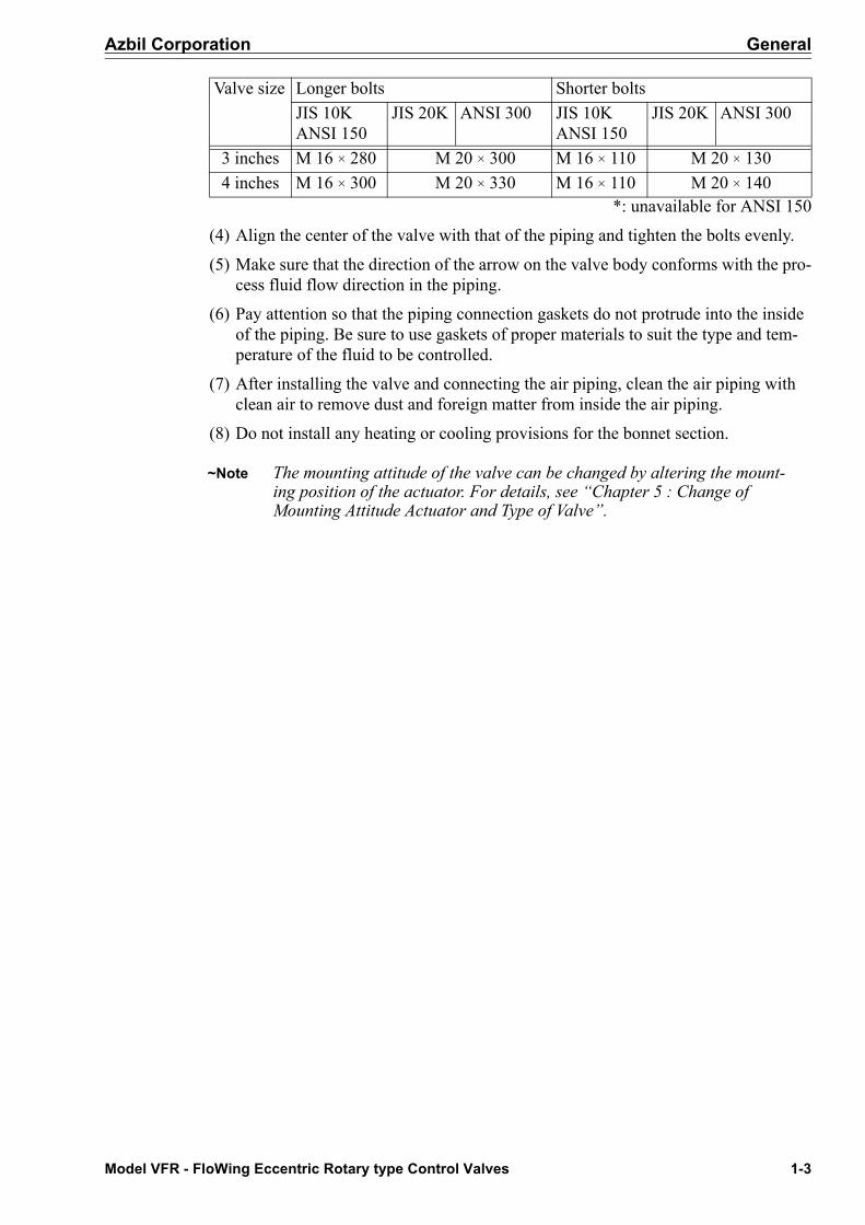
(4) Align the center of the valve with that of the piping and tighten the bolts evenly.
(5) Make sure that the direction of the arrow on the valve body conforms with the pro-cess fluid flow direction in the piping.
(6) Pay attention so that the piping connection gaskets do not protrude into the inside of the piping. Be sure to use gaskets of proper materials to suit the type and tem-perature of the fluid to be controlled.
(7) After installing the valve and connecting the air piping, clean the air piping with clean air to remove dust and foreign matter from inside the air piping.
(8) Do not install any heating or cooling provisions for the bonnet section.
~Note The mounting attitude of the valve can be changed by altering the mount-ing position of the actuator. For details, see “Chapter 5 : Change of Mounting Attitude Actuator and Type of Valve”.
Valve size Longer bolts Shorter boltsJIS 10KANSI 150
JIS 20K ANSI 300 JIS 10KANSI 150
JIS 20K ANSI 300
3 inches M 16 × 280 M 20 × 300 M 16 × 110 M 20 × 1304 inches M 16 × 300 M 20 × 330 M 16 × 110 M 20 × 140

General Azbil Corporation
1-4 Model VFR - FloWing Eccentric Rotary type Control Valves
1-3: Inspection and maintenance of the installed valveFollow the steps given below when inspecting and servicing an installed valve.
(1) Check that there is no leak from the air piping.
(2) Check that there are no loose clamping-bolts or nuts on the diaphragm case.
(3) Check that there is no leak from the gland packing. Tighten the packing flange nuts as required.
(4) Check that there is no leak from the piping gaskets and check for any clamping bolts and nuts.
(5) To lubricate a valve which has a lubricator, proceed as follows:
(a) Prepare the correct type of grease referring to the grease number indicated on the nameplate.
(b) Tightly close the lubricator handwheel.
(c) Remove the squeeze screw and apply grease.
(d) While opening the lubricator handwheel, squeeze grease into the valve by rotat-ing the squeeze screw.
(e) Repeat procedures (b), (c) and (d) until grease has been sufficiently fed into the valve. When finished, close the lubricator handwheel.
Figure 1-4 Lubricator

Model VFR - FloWing Eccentric Rotary type Control Valves 2-1
Azbil Corporation
Chapter 2 : Valve Body
2-1: DescriptionFigure 2-1 shows a cutaway view of the valve body section of the model VFR Eccen-tric Rotary Valve. The valve body section consists of a valve body, which is con-structed as one with a bonnet, and of a valve plug, a seat ring, and other trim parts.
Cross sections and nomenclature of the valve body section are shown in Figure 2-2.
Figure 2-1 Cutaway View
*: For a valve without lubricator**: For a valve with lubricator, this space must be filled with packing instead of the spring
Figure 2-2 Cross Sections

Valve Body Azbil Corporation
2-2 Model VFR - FloWing Eccentric Rotary type Control Valves
2-2: DisassemblyFor the disassembly of the valve body section, dismantle the actuator observing the disassembly instructions of given in chapter 2 and then proceed as follows:
(1) Remove the clamping-bolts from the packing flange.
(2) Remove the packing flange and packing follower.
(3) Pull out the valve stem together with other gland parts (key, main bushing, spring, packing ring and packing). (For 10 inches and 12 inches valves, pull out only the valve stem).
~Note If the valve stem will not readily come out, pull it out in the following pro-cedure:
(a) Remove several pieces of packing(b) Set up a pipe, a stud bolt, a nut and a washer as shown in Figure 2-3 then
turn the nut to pull out the valve stem. (When installing the cam holder on the valve stem end, apply a locking agent).
(4) Remove the valve plug from the plain bearing.
(5) Pull out the valve plug from the downstream side.
(6) Remove the seat retainer by turning it counterclockwise with a seat ring remover-clamper (a special tool available as an option). For the seat ring remover-clamper, see Figure 2-4.
(7) Remove the seat ring. Inspect all of the removed parts and replace defective ones, if any, with new ones.
Figure 2-3
(mm)
Figure 2-4 Seat Ring Remover-clamper
A T D W
3 in. 19.5 10 66 24
4 in. 19.5 10 85 24

Azbil Corporation Valve Body
Model VFR - FloWing Eccentric Rotary type Control Valves 2-3
2-3: Assembly(1) Insert the valve plug in the valve body and press it against the plain bearing.
(2) Insert the valve stem into the main bushing and insert the key in the key slot of the valve stem. (See Figure 2-5)
(3) Insert the valve stem into the valve body and slide the key through the key slot of the valve plug. (See Figure 2-5)
(4) Install the gland parts. For packing pay attention to whether the valve is with or without a lubricator. For assembly, see Figure 2-6.
~Note Insert packing in such a manner so that their ends are positioned alter-nately.
Figure 2-5 Plug and Stem

Valve Body Azbil Corporation
2-4 Model VFR - FloWing Eccentric Rotary type Control Valves
(5) While holding the valve plug open, install the seat ring and clamp it with the seat retainer to a finger-tight force.
~Note Apply liquid packing to the seat ring. (See Figure 2-7).Apply an anti-binding agent to the threaded section of the seat retainer.
(6) Turn the valve stem so that the valve plug is pressed against the seat ring. Then, tighten the seat retainer with the seat ring remover-clamper.
Figure 2-6 Packing Section
Figure 2-7 Seat ring

Model VFR - FloWing Eccentric Rotary type Control Valves 3-1
Azbil Corporation
Chapter 3 : Actuator
3-1: DescriptionThe model RSA2 Actuator is a pneumatic and spring type diaphragm motor designed specifically for rotary type control valves. It holds the valve plug in a position where the pneumatic force and pneumatic force are mutually balanced.
For proportional control operation, a dedicated positioner is incorporated.
Valve position can be mutually adjusted using the handwheel. As the handwheel is rotated counterclockwise*, the actuator stem moves downward. (* The open/close directions are indicated on the direction indicator plate on the handwheel).
Actuator Azbil Corporation
3-2 Model VFR - FloWing Eccentric Rotary type Control Valves
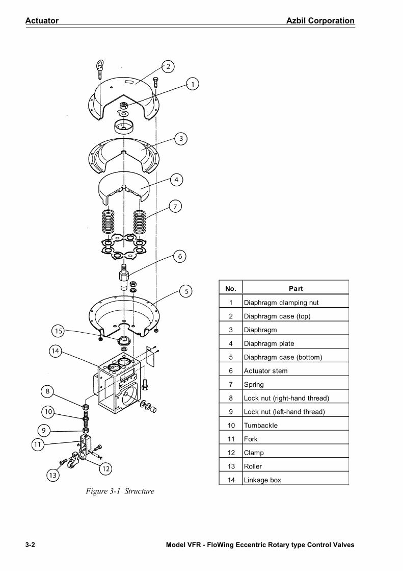
Figure 3-1 Structure
No. Part
1 Diaphragm clamping nut
2 Diaphragm case (top)
3 Diaphragm
4 Diaphragm plate
5 Diaphragm case (bottom)
6 Actuator stem
7 Spring
8 Lock nut (right-hand thread)
9 Lock nut (left-hand thread)
10 Turnbackle
11 Fork
12 Clamp
13 Roller
14 Linkage box

Azbil Corporation Actuator
Model VFR - FloWing Eccentric Rotary type Control Valves 3-3
3-2: Adjustment of actuatorThe actuator must be adjusted when its action has shifted or after it has been over-hauled. Before adjusting the actuator, turn the manual handwheel fully clockwise as viewed from direction indicator plate.
(1) Connect the air piping to the actuator through a pressure regulator.
(2) Loosen the lock nuts of the turnbuckle. One nut is right-hand threaded (No. 8) and the other is left-hand threaded (No. 9). (See Figure 3-1).
(3) By adjusting the pressure regulator, apply to the actuator a pressure corresponding to the upper limit of the spring range if the valve is in direct-action mode or a pres-sure corresponding to the lower limit of the spring range if the valve is in reverse-action mode.
(4) Use a wrench to turn the hex section of the turnbuckle in the direction given below until rotation becomes heavy and the parts on the clamp shaft do not rotate.
• For a direct-action valve, turn in the direction that the exposed thread of the turnbuckle increase.
• For a reverse-action valve, turn in the direction that the exposed threads of the turnbuckle decrease.
(5) Next, align the pointer with the S index of the scale.
(6) Loosen the lower one (the lock out) of the double nuts and move it back to the original position to tighten the fork.
(7) To adjust the positioner, see Chapter 4 “Valve Positioner”.
3-3: Removing actuator from valve body(1) At first, remove the positioner from the valve body by referring to Chapter 4
“Valve Positioner”.
(2) After removing the positioner, remove the nut and then remove the cam and pointer from the valve stem end. (See Figure 3-2) (for VPR positioner only)
(3) For a reverse-action valve, the initial compression force is being applied to the actuator stem, therefore loosen the locknut which fastens the actuator stem to the fork and then relieve the force by turning (anti-clockwise) the actuator stem with the turnbackle.
Figure 3-2

Actuator Azbil Corporation
3-4 Model VFR - FloWing Eccentric Rotary type Control Valves
(4) Loosen the bolts (hex-hole head) of the clamps which connect the actuator stem to the valve stem. (See Figure 3-3)
(5) Remove the four bolts which clamp the yoke to the valve body and then remove the actuator from the valve body.
3-4: Disassembly of actuatorTo disassemble the actuator for parts replacement or any other servicing, follow the procedure described below. (See Figure 3-1). When disassembling the actuator, take care not to damage the diaphragm or piston.
(1) Remove the clamping bolts (except the pair of eyebolts) from the diaphragm case (top). Alternately and evenly loosen the pair of eyebolts last.
(2) Loosen the anti-rotation lock nut and remove the fork from the end of the actuator.
(3) Pull the folded diaphragm out upwards, exercising care not to damage it.
(4) Next, while holding the outer section of the diaphragm plate, remove the dia-phragm clamping-nuts from the top of the diaphragm section.
(5) To disassemble the fork and clamp, remove the E-clip and then pull out the con-necting pin (Figure 3-4)
Figure 3-3
Figure 3-4

Azbil Corporation Actuator
Model VFR - FloWing Eccentric Rotary type Control Valves 3-5
3-5: Assembly of actuatorThe mounting positions of parts differ depending on whether the valve is direct action or reverse action, therefore confirm the action of the valve by referring to the name-plate prior to assembling the actuator.
For the assembly of the actuator, proceed as follows:
(1) Assemble the parts by following, in the reverse order, the steps given in subsection “3-4: Disassembly of actuator”.
~Note To assemble the fork and clamp, pay attention to the direction of the con-vex section of the fork and assemble them as shown in Figure 3-5.
(2) Set the diaphragm case (top) and fix it evenly and securely with the bolts and nuts. (See Figure 3-6).
(3) Before fixing the clamp onto the valve stem, adjust the gap between the spring compression nut and the fork lock nut at approximately 7 mm. (See Figure 3-7).
(4) Assemble the valve body following, in the reverse order, the procedure given in subsection “3-4: Disassembly of actuator”.
Figure 3-5
Figure 3-6 Figure 3-7

Actuator Azbil Corporation
3-6 Model VFR - FloWing Eccentric Rotary type Control Valves
3-6: Mounting actuator on valve bodyTo mount the actuator on the valve body, follow in the reverse order, the procedure given in section “3-3: Removing actuator from valve body”. After mounting the actua-tor, adjust the actuator as described in section “3-2: Adjustment of actuator”.
3-7: Manual device (Handwheel)The manual device on the actuator has a function as a limit stopper in addition to the function as a conventional manual control device for the valve.
3-7-1: Setting for automatic operation
When the valve is operated in the automatic mode, set the manual devices as follows:
(1) Release the handwheel lock by turning it clockwise (as viewed downwards from the indicator plate).
(2) Pull the handwheel shaft out as far as it can by turning the handwheel clockwise in the same direction as in Step (1).
(3) Lock the handwheel by turning the handwheel lock counterclockwise.
(4) Keep the handwheel in this state while the valve is in the automatic mode.
3-7-2: Operation for manual control
First, set the bypass cock (See Figure 4-6.) of the positioner to the “on” position.
When the handwheel lock is released and the handwheel is rotated counterclockwise as viewed from the direction of the indicator plate, the valve closes if it is of the direct action type or it opens if it is of the reverse action type. For manual control of the flow with the valve, turn the handwheel to the required position in the applicable direction referring to the direction on the indicator plate and tighten the handwheel lock at this position.
Be sure to set the valve as described in subsection “3-7-1: Setting for automatic opera-tion” before operating the valve in automatic mode.
3-7-3: Operations as limit stopper
The handwheel can be used also as a limit stopper which means a stopper for a maxi-mum opening when in direct action mode or as a stopper for a minimum opening when the reverse action mode.
(1) Release the handwheel lock. Turn the handwheel to the required position in the required direction referring to the direction on the indicator plate.
(2) Tighten the handwheel lock.
For automatic operation without limit stopping effect, set the handwheel as described in subsection “3-7-1: Setting for automatic operation”.

Model VFR - FloWing Eccentric Rotary type Control Valves 4-1
Azbil Corporation
Chapter 4 : Valve Positioner
4-1: Description(1) Electro-pneumatic positioner.
For instructions on using the valve positioner, refer to the following operator’s manuals:
CM2-AVP300-2001 (for model AVP)
CM2-8313-0100 (for model HEP)
(2) Pneumatic Positioner.
The valve posiitoner is mounted on a RSA2 actuator and has a function of posi-tioning the valve plug accurately and rapidly in a position corresponding to the pneumatic signal received from the controller.
The valve positioner is comprised of the following:
• Input gauge• Output gauge• Bypass cock• Input bellows• Flapper-nozzle mechanism• Pilot relay• Cam• Cam follower• Feedback spring• Feedback lever
Figure 4-1 Front view

Valve Positioner Azbil Corporation
4-2 Model VFR - FloWing Eccentric Rotary type Control Valves
4-2: Operating principleThe valve positioner employs a force balance mechanism. See Figure 4-4 and
Figure 4-5 for its operating principle.
Figure 4-2 View with cover removed Figure 4-3 Rear view
Figure 4-4 Block Diagram of the Positioner
Figure 4-5 Operating principle of the positioner

Azbil Corporation Valve Positioner
Model VFR - FloWing Eccentric Rotary type Control Valves 4-3
4-3: Bypass cock
4-3-1: Function of bypass cock
The supply air bypass cock mechanism is found at the bottom of the valve positioner. One can select between the “ON” state for “operation with positioner” and the “SUP” state for “operation with the supply air” as shown in Figure 4-6. When in the “SUP” state, the supply air bypasses the pilot relay and it is fed directly to the actuator, thereby enabling the following:
(1) The valve opening can be directly controlled with the supply air.
(2) Since the pilot relay is isolated from the supply air and output air, the pilot relay can be inspected or serviced simply by shutting the input signal air off.
4-3-2: Installation of bypass cock
To install a bypass cock which has been removed for gasket replacement or some other service, install it while referring to Figure 4-7. In this case, apply silicone grease spar-ingly to the surface faces of the gasket. If a new gasket is used, place it so that its white surfaces outwards and, after fully tightening the mounting screw (cross-hole head), loosen it by giving it an 1/3 to 1/4 turn.
Figure 4-6 Switching by bypass cock
Figure 4-7 Exposed view of the bypass cock

Valve Positioner Azbil Corporation
4-4 Model VFR - FloWing Eccentric Rotary type Control Valves
4-4: Selecting CAM characteristicsTo change the valve characteristics, select a proper cam and install it.
(For installation and adjustment, see the respective sections).
4-4-1: CAM characteristics
A single sheet of cam for the positioner can satisfy linear characteristics or equal-per-cent characteristics.
4-4-2: Use of equal-percent camWhen the inherent characteristics of the valve are linear but equal-percent characteris-tics are required by the process, the control characteristics of the valve can be con-verted into an equal-percent type simply by using an equal-percent cam.
4-4-3: Selecting a camSelect a proper cam as follows:(1) Check whether the valve is direct action (air-to-close) or reverse action (air-to-
open).
(2) By referring to Figure 4-9, select a proper cam which will provide the required flow characteristics for the process.
Figure 4-8 Cam characteristics
Figure 4-9 Example of using a cam - for Flowing Valve (full port, reverse action)

Azbil Corporation Valve Positioner
Model VFR - FloWing Eccentric Rotary type Control Valves 4-5
4-5: Removal and installation of positioner
4-5-1: Removal
(1) Disconnect the air piping from the positioner.
(2) Loosen the two clamping-bolts (M5, hex-hole head) with a hex wrench (4 mm) and remove the positioner cover. (See Figure 4-10)
(3) Loosen the two inside clamping-bolts (M6, hex-hole head) with a hex wrench (5 mm). The positioner is ready for removal. (See Figure 4-11).
4-5-2: Installation
For adjustment of the positioner after installation, see section “4-6: Adjustment of Positioner”.(1) Confirm actuator specifications and cam characteristics by referring to the name-
plate and check the following three items:a) Direction action (air-to-close) or reverse action (air-to-open)b) Spring range of actuatorc) Cam characteristics
Figure 4-10 Figure 4-11
Valve Positioner Azbil Corporation
4-6 Model VFR - FloWing Eccentric Rotary type Control Valves
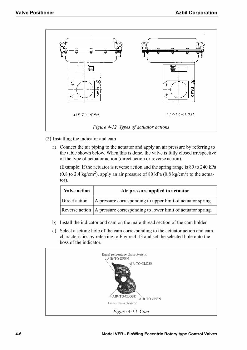
(2) Installing the indicator and cam
a) Connect the air piping to the actuator and apply an air pressure by referring to the table shown below. When this is done, the valve is fully closed irrespective of the type of actuator action (direct action or reverse action).
(Example: If the actuator is reverse action and the spring range is 80 to 240 kPa (0.8 to 2.4 kg/cm2), apply an air pressure of 80 kPa (0.8 kg/cm2) to the actua-tor).
b) Install the indicator and cam on the male-thread section of the cam holder.
c) Select a setting hole of the cam corresponding to the actuator action and cam characteristics by referring to Figure 4-13 and set the selected hole onto the boss of the indicator.
Figure 4-12 Types of actuator actions
Valve action Air pressure applied to actuator
Direct action A pressure corresponding to upper limit of actuator spring
Reverse action A pressure corresponding to lower limit of actuator spring.
Figure 4-13 Cam

Azbil Corporation Valve Positioner
Model VFR - FloWing Eccentric Rotary type Control Valves 4-7
d) Engage the indicator with the cam holder serration in such a manner that the linear section of the indicator becomes as parallel as possible with the imagi-nary line of the reference line on the bearing cover. At this point, fix the cam with the spring washer and nut (M8). (See Figure 4-14).
e) Release the air pressure applied to the actuator and disconnect the air piping.
(3) Installing the positioner
a) Loosen the two clamping -bolts (M5, hex-hole head) with a hex wrench (4 mm) and remove the positioner cover.
b) Mount the positioner (in an attitude so that the bypass cock is positioned down-ward) on the bearing cover with two bolts (M6, hex-hole head) and spring washers using a hex wrench (5 mm).
(4) Connecting the air piping
Figure 4-14 Installation of indicator and cam (for direct action and linear characteristics)
Figure 4-15 Installation of positioner

Valve Positioner Azbil Corporation
4-8 Model VFR - FloWing Eccentric Rotary type Control Valves
Connect air piping between the union joint and the three air connection ports (IN, SUP, OUT, PT 1/4 tap thread) on the side plate of the positioner.
IN: Input pneumatic pressure from controller
SUP: Air supply
OUT: Output pneumatic pressure to actuator
~Note Apply liquid packing to the threaded sections of the connectors. Do not use seal tape lest air paths of the positioner should be clogged.
4-6: Adjustment of PositionerThe positioner installed on a valve is shipped after being adjusted at the factory. When it is replaced, however, the newly installed positioner must be adjusted using the fol-lowing procedure.
(1) Set the bypass cock to “on”.
(2) Confirm the positioner input air pressure range, supply air pressure and actuator spring range by referring to the nameplate.
(3) Feed the supply air to the positioner.
(4) Explanations hereunder are done separately for a direct- action positioner and a reverse action positioner, assuming an input air pressure range of 20 to 98 kPa (0.2 to 1.0 kg/cm2) for both cases.
~Note If the input pressure range of the positioner is 20 to 60 kPa (0.2 to 0.6 kg/cm2), substitute 98 kPa (1.0 kg/cm2) with 60 kPa (0.6 kg/cm2)and 20 kPa (0.2 kg/cm2) with 60 kPa (0.6 kg/cm2) in the following steps.
For direct action positioner (air-to-open)
(5) Set the input air pressure to 20 kPa (0.2 kg/cm2)
(6) Turn the zero adjustment knob so that the output pressure of the positioner becomes the lower limit of the actuator spring range. When this is done, the indica-tor will indicate the “S” position.

Azbil Corporation Valve Positioner
Model VFR - FloWing Eccentric Rotary type Control Valves 4-9
(Example: If the spring range of the actuator is 80 to 240 kPa (0.8 to 2.4 kg/cm2), set the output pressure of the positioner to 80 kPa (0.8 kg/cm2).)
(7) Set the input pressure to 80 kPa (0.8 kg/cm2)
(8) Loosen the lock screw with a flat headed screwdriver and adjust the SPAN control so that the indicator indicates 0 position.
For direct action positioner (air-to-close)
(5) Set the input air pressure to 80 kPa (0.8 kg/cm2)
(6) Turn the zero adjustment knob so that the output pressure of the positioner reaches the upper limit of the actuator spring range.When this is done, the indicator will indicate the “S” position.
(Example: If the actuator spring range is 80 to 240 kPa (0.8 to 2.4 kg/cm2), set the output pressure of the positioner to 240 kPa (2.4 kg/cm2).)
(7) Set the input pressure to 20 kPa (0.2 kg/cm2)
(8) Loosen the lock screw with a flat headed screwdriver and so adjust the SPAN con-trol so that the indicator indicates 0 position.
(9) Repeat procedures (5) to (8) several times.
(10)When adjustment has been completed, tighten the lock screw of the SPAN control with a flat headed screwdriver.
Figure 4-16 Adjustments of the positioner

Valve Positioner Azbil Corporation
4-10 Model VFR - FloWing Eccentric Rotary type Control Valves
4-7: Maintenance of positioner
4-7-1: Precautions for operation
(1) Use only clean filtered air for the air supply, lest the nozzle or pilot relay be clogged with foreign particles contained in the air supply.
(2) If the positioner is installed outdoors, be sure to install the positioner in such atti-tude that the positioner cover is positioned vertically in order to prevent ingression of water.
4-7-2: Troubleshooting of positioner
If the positioner experiences problems or it happens to malfunction, refer to the trou-bleshooting chart on page 4-11 and follow the procedures described therein.
4-7-3: Cleaning of restriction
If the restriction has become clogged with foreign particles and the positioner has mal-functioned, remove the M5 bolts (hex-hole head) and M3 bolt (hex-hole head) with 4 mm and 2.5 mm hex wrenches, respectively; remove the spacer, and then clean the restriction with a 0.3 mm wire.
Be sure to install the bias spring when assembling the pilot relay.
Figure 4-17 Disassembly of the pilot relay

Azbil Corporation Valve Positioner
Model VFR - FloWing Eccentric Rotary type Control Valves 4-11
Troubleshooting chart
~Note The deviation unit is required to be disassembled. Disassembly should be done by a service agent of Azbil Corporation. Disassembly by the customer is not recommended.
Symptom Cause RemedyNo output 1. Incorrect adjustment 1. Refer to section “4-6: Adjustment of
Positioner”.2. Incorrect setting of supply
air pressure2. Refer to section “4-6: Adjustment of
Positioner”.3. Clogged restriction 3. Refer to section “4-7-3: Cleaning of
restriction”.4. Incorrect mounting of cam 4. Refer to section “4-5: Removal and
installation of positioner”.5. Defective bellows 5. * See note.
Output pressure does not decrease
1. Incorrect adjustment 1. Refer to section “4-6: Adjustment of Positioner”.
2. Clogged restriction 2. * See the note.3. Bias spring 3. Refer to section “4-7-3: Cleaning of
restriction”.4. Bypass cock 4. Turn ON positively5. Incorrect mounting on cam 5. Refer to section “4-5: Removal and
installation of positioner”.Unsatisfactory linearity 1. Incorrect adjustment 1. Refer to section “4-6: Adjustment of
Positioner”.2. Incorrect mounting of cam 2. Refer to section “4-5: Removal and
installation of positioner”.Large hysteresis 1. Loose bolts or nuts 1. Tighten loose bolts or nuts
2. Defective bellows 2. * See the note.Sluggish action 1. Bypass cock 1. Set to ON positively
2. Clogged restriction or bel-lows
2. * See note
Hunting occurs 1. Friction in valve body or actuator
1. Inspect the valve body and actuator

Valve Positioner Azbil Corporation
4-12 Model VFR - FloWing Eccentric Rotary type Control Valves

Model VFR - FloWing Eccentric Rotary type Control Valves 5-1
Azbil Corporation
Chapter 5 : Change of Mounting Attitude Actua-tor and Type of Valve
The model VFR valve can be modified so that the mounting attitude of its actuator can be changed and the type of its action can be changed without requiring any additional parts.
5-1: Change of mounting attitude of actuatorThe actuator can be installed in any one of the four attitudes shown in Figure 5-1. The standard mounting attitudes are as shown as 1 and 5 in Figure 5-1. When the actuator is installed in an attitude other than the standard attitudes, install the main cap on the air vent of diaphragm case (bottom).
(1) Remove the actuator from the valve body by referring to “Chapter 3 : Actuator”
(2) Set the actuator in the desired attitude and fix the actuator to the valve body. In this case, make sure that the roller of the clamp is correctly set on the handwheel shaft.
(3) Adjust the actuator referring to section “3-2: Adjustment of actuator”. For the posi-tioner, refer to section “4-6: Adjustment of Positioner”.
5-2: Change of valve action(1) Detach the clamp from the valve stem by removing the hex - socket bolt of the
clamp (Figure 3-4)
(2) Change clamp and fork referring to Figure 3-5.
(3) Disassemble the actuator by following the procedures in section “3-4: Disassem-bly of actuator”, then reassemble the diaphragm case (bottom) by referring to Fig-ure 5-2.
Figure 5-1 Mounting attitudes of the actuator

Change of Mounting Attitude Actuator and Type of Valve Azbil Corporation
5-2 Model VFR - FloWing Eccentric Rotary type Control Valves
(4) Change the direction indicator plate of the handwheel to the corresponding direc-tion (D for direct action or R for reverse action). (see Figure 5-3.)
(5) For assembly, follow procedures (1) - (4) in the reverse order.
(6) When valve operation is changed between direct action and reverse action, the air tubing connection port will be changed to the opposite position. (See Figure 5-2.)
Figure 5-2

Azbil Corporation Change of Mounting Attitude Actuator and Type of Valve
Model VFR - FloWing Eccentric Rotary type Control Valves 5-3
Figure 5-3

Change of Mounting Attitude Actuator and Type of Valve Azbil Corporation
5-4 Model VFR - FloWing Eccentric Rotary type Control Valves

Document Number: CM2-8130-0100
Document Name: FloWing Eccentric Rotary Type Control ValveModel: VFR (3, 4 inches)User’s Manual
Date: 7th edition: Aug. 2012
Issued/Edited by: Azbil Corporation