Embed Size (px)
Citation preview
NASA/TM--2001-211284
Flow Visualization in Evaporating Liquid
Drops and Measurement of Dynamic
Contact Angles and Spreading Rate
Nengli Zhang
Ohio Aerospace Institute, Brook Park, Ohio
David E Chao
Glenn Research Center, Cleveland, Ohio
Prepared for the
2001 International Mechanical Engineering Congress and Exposition
sponsored by the American Society of Mechanical Engineers
New York City, New York, November 11-16, 2001
National Aeronautics and
Space Administration
Glenn Research Center
November 2001
https://ntrs.nasa.gov/search.jsp?R=20020011038 2018-05-27T22:49:27+00:00Z

NASA Center for Aerospace Information7121 Standard Drive
Hanover, MD 21076
Available from
National Technical Information Service
5285 Port Royal Road
Springfield, VA 22100
Available electronically at http://gltrs.grc.nasa.gov/GLTRS

FLOW VISUALIZATION IN EVAPORATING LIQUID DROPS ANDMEASUREMENT OF DYNAMIC CONTACT ANGLES
AND SPREADING RATE
Nengli Zhang _'and David F. Chao
National Aeronautics and Space AdministrationGlenn Research Center
Cleveland, Ohio 44135
SUMMARY
A new hybrid optical system, consisting of reflection-refracted shadowgraphy and top-view photography, isused to visualize flow phenomena and simultaneously measure the spreading and instant dynamic contact angle in a
volatile-liquid drop on a nontransparent substrate. Thermocapillary convection in the drop, induced by evaporation,and the drop real-time profile data are synchronously recorded by video recording systems. Experimental resultsobtained from this unique technique clearly reveal that thermocapillary convection strongly affects the spreading
process and the characteristics of dynamic contact angle of the drop. Comprehensive information of a sessile drop,
including the local contact angle along the periphery, the instability of the three-phase contact line, and the deforma-tion of the drop shape is obtained and analyzed.
INTRODUCTION
Most studies on liquid drop spreading have focused on nonvolatile liquid sessile drops for their simplicity both
in experimental measurements and theoretical analysis. The occurrence of liquid evaporation is, however, inevitable.The affects of evaporation on the spreading and contact angle become very important for a more complete under-
standing of these processes. It has been found that evaporation can induce Marangoni-B6nard convection in sessiledrops (ref. 1). The fluid flow in the drop is attributable to the surface-tension mechanism from local variations in the
surface temperature. The effect of convection in the drop on the wetting and spreading processes, however, is notclear. Flow in a small sessile drop takes place on a microscopic scale and cannot be viewed by eye. Although con-vective flow, if any, can be observed under a microscope by means of microparticle tracers, the field under investi-
gation is inevitably intruded. Optical methods are the only nonintrusive means of visualizing flow in small fluidvolumes. Both the Schlieren method and Mach-Zehnder interferometry, however, are unsuitable for visualizing flow
motion in an evaporating sessile drop. The only useful optical method is shadowgraphy (ref. 2).Shadowgraphy is the simplest of the optical visualizing methods, which is roughly sensitive to changes in the
second derivative of the density of the field under investigation (ref. 3). In a locally increasing density field, the fluidacts like a convex lens. In a decreasing density field, it has the effect of a concave lens. When turbulent motionoccurs in the field, a fluctuating density creates a distribution of tiny convex and concave lenses that are continu-
ously changing in shape and location. The effect has been utilized to investigate the internal convection in evaporat-
ing drops (refs. 2 and 4). A laser-shadowgraphic system developed by Zhang and Yang (ref. 5) was modified andsuccessfully used to visualize the thermocapillary convection inside and to measure the spreading rate of volatiledrops, simultaneously (refs. 4 and 6). It was found that evaporation and thermocapillary convection strongly affect
the spreading process. Unfortunately, the laser-shadowgraphic system, including its modified version, can only beapplied to sessile drops spreading on transparent substrates. Allain et al. (ref. 7) suggested using the reflection of aparallel beam on the surface of a sessile drop to measure the contact angle of the drop on a non-transparent substrate.
Obviously, it can work only when the surface of the tested liquid has enough reflectance. However, the light reflec-
tivity on the surface of most common liquids is insufficient and, therefore, this method is rarely applied in practice.Another major disadvantage of this method is that it does not allow visualization of the flow in the drop.
This present paper suggests a hybrid optical system consisting of a reflection-refracted shadowgraphy and top-
view photography to simultaneously visualize the convective flow, and measure the dynamic contact angles andspreading rate of volatile sessile drops on a nontransparent substrate.
"Phone:216--433-8750: Fax: 216---433-8050:e-mail: [email protected]
NASA/TM--2001-211284 1
APPARATUS
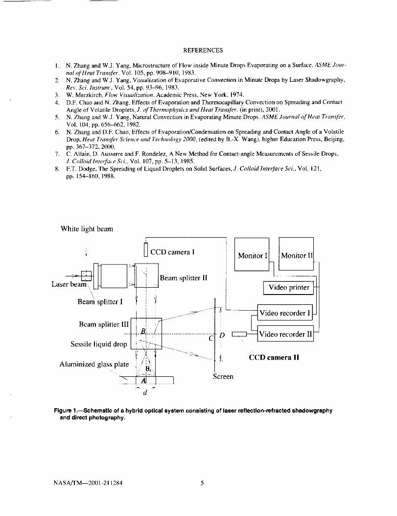
Laserreflection-refractedshadowgraphyanddirecttop-viewphotographyweresimultaneouslyachievedbyusingahybridopticalsystem.Theapparatusconsistedofa laserlight,awhitelight,acollimator,threebeamsplit-ters,twovideorecordingsystems(eachconsistingbyaCCDzoomcamera,videorecorderandmonitor),atestplate(aluminizedglassplate),andascreen,asillustratedinfigure1.A uniphase Model 1105p, 10-mW cylindricalhelium-neon laser and an Olympus Model Highlight 2000 were used as the laser source and the white-light source,
respectively. Both light beams passed through the collimator, Newport Model LC-075, via Beam splitter I, and col-limated to parallel beams coincidentally, and then reflected by Beam splitter II to pass perpendicularly through asessile drop, situated on an aluminized glass plate. The laser beam produced a reflection-refracted image of the ses-
sile drop on a screen, and the white beam provided a sharp photograph of the top view of the drop. The drop top-view was recorded on Video recording system I, and the laser reflection-refracted shadowgraphic image on Video
recorder II. The two recorders were controlled synchronously.Before each test, the aluminized glass plate was cleaned by ethanol and wiped by lens-cleaning tissue, and then
shelved in open air, covered by a soft tissue, for at least 24 hr. By this method, the plate surface was freed of residual
liquid molecules and remained free of impurities from the ambient air. The test liquid was carefully deposited on the
plate by a microsyringe to form a 1.5 to 2.5 _tl sessile drop. The origin of spreading and evaporation time was takenas the moment when the microsyringe was detached from the liquid body.
RESULTS AND DISCUSSION
Consider a sessile drop placed in the collimated light beam of the hybrid optical-system so that the hybrid light
beam traverses the drop volume from top to bottom and then is reflected out of the volume as shown in figure 1. Thedetailed path of the beam traveling through the drop is that the collimated incident light is refracted by the sessiledrop and then reflected on the substrate surface, returning to the air-liquid interface, and finally refracted out of the
drop. The refracted light-beam is directed to the horizontal by Beam splitter III and intercepted by a vertical screen,forming a shadowgraphic image. This is referred to as reflection-refracted shadowgraphic image. As is well known,
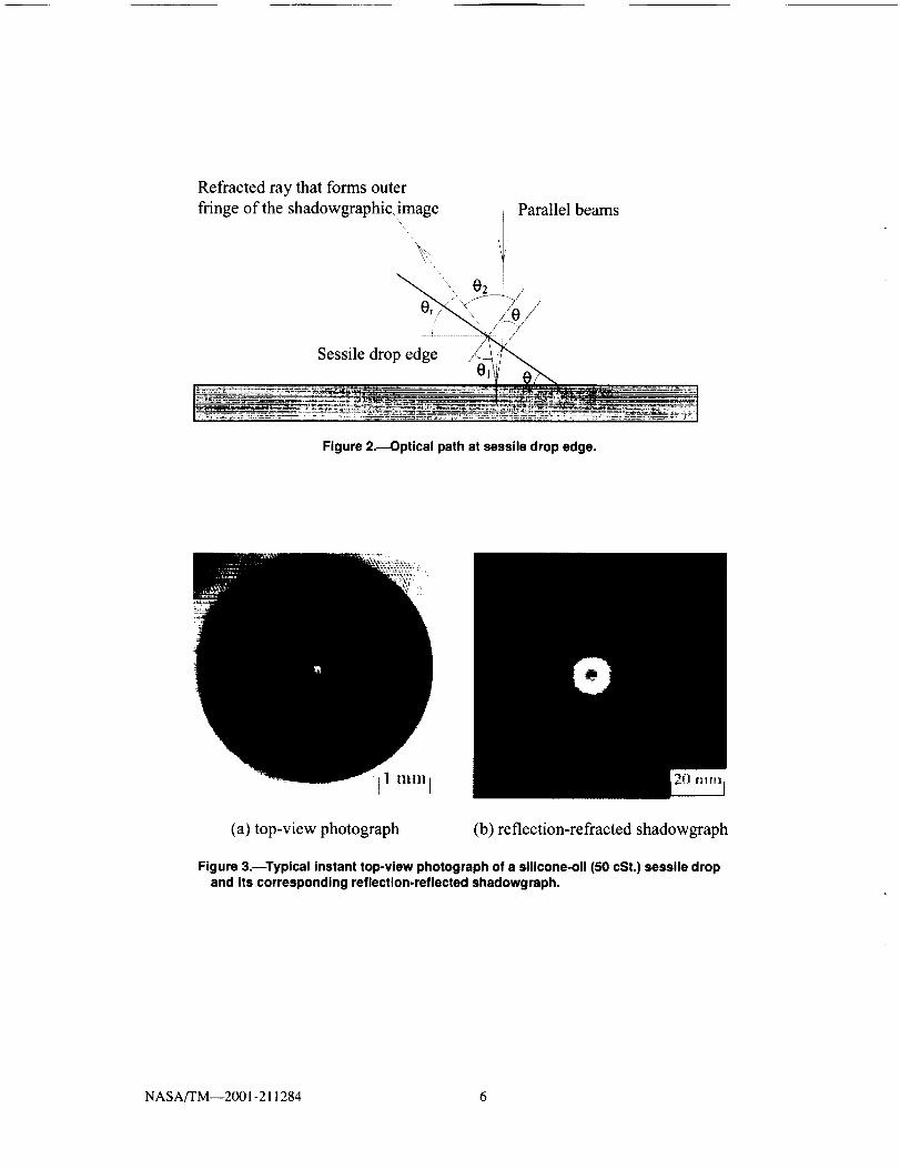
a small sessile drop can be considered a spherical cap. Consequently, the incident angle of the parallel beam on thedrop surface reaches its maximum at the edge of the drop. It is the refracted ray out of the drop edge that forms the
outer fringe of the reflection-refracted shadowgraphic image. The detailed optical path at the drop edge is shown infigure 2. The image brightness at a given point is linearly related to the integral average of the second derivative of
the refractive index over the passage of a ray, which approximately equals the double of the local height of the drop.The entire image, being a map of the distribution of the average of the second derivative of the refractive index over
the ray passage, represents the distribution of the average second derivative of the temperature along the ray passagein the evaporating drop. From a real-time change of the image, the fluid motion in the drop, if any, can be clearlyobserved.
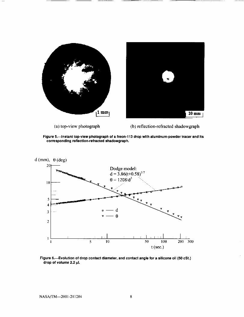
Figures 3(a) and (b) show an instant top-view photograph and corresponding reflection-refracted shadowgraph
of a 2.5 _tl silicone-oil (50 cSt) drop, spreading on an aluminized glass plate in open air. The bright circle at the cen-
ter of the top-view photograph, figure 3(a), is formed by reflection of the parallel light beams at the drop summit.The bright annulation at the center of figure 3(b) represents the projected images of the parallel beam and of thedrop located in the middle of the beam. The instant contact diameter of the drop, a key parameter of drop spreading,
can be measured directly from the top-view photograph shown in figure 3(a), or from its projected image that repre-sented by the dark circle at the center of figure 3(b). However, the latter has a large error in reading because its small
image was embedded in a much larger shadowgraphic image and, therefore, cannot accurately be measured. One ofthe advantages of the method described in this article is the ability to record the top view of the drop and itsreflection-refracted shadowgraphic image synchronously. The internal convective flow field of the drop can be visu-
alized while the contact diameter and contact angle is accurately measured, and, therefore, effects of the flow motionon the spreading can be determined. For nonvolatile liquids, the sessile drop spreads calmly without any detectable
internal flow convection, as shown in figure 3(b).However, in volatile drops, evaporation can induce thermocapillary convection under certain conditions,
depending on the properties of the liquid. Figures 4(a) to (c) depict the reflection-refracted shadowgraphic images offreon- 113, n-pentane, and ethanol drops, respectively, evaporated on an aluminized glass plate in open air. The dif-
ferent evaporation rates and physical properties of the liquids produced different internal flow patterns and stabilitiesof the contact line. The thermocapillary convection in the freon-113 drops can be induced by evaporation from the
very beginning, even before the syringe detaches from the drops. An instant reflection-refracted shadowgraph of a
NASA/TM--2001-211284 2
freon-113drop,showninfigure4(a),clearlypresents the typical four-region flow structure described by Zhang and
Yang (refs. 1). The flow motion in the midway ring-shaped region of the drop is very strong, while a weak flowoccurs in a very narrow region at the bottom of the drop, and a small stagnation region exists at the summit of the
drop. On the other hand, the convection in n-pentane drops occurs after the drops spread for a short time. Beforethat, there is no convection in the drop at all. The flow pattern in the n-pentane drops is obviously different from thatin the freon-113 drops. Active flow occurs at the bottom of the drop instead of in the midway ring-shaped region.
where a weaker flow convection can be observed, leaving the top region stagnant.
The ethanol drops exhibit no flow motion throughout their lifetime as their evaporation rate is too low to inducethermocapillary convection. However, the ethanol drops develop an unstable three-phase contact line, where the
interface tensions, contact angle, and Laplace capillary-pressure determine the shape of the interlaces. The unstablethree-phase line gives a jagged periphery in the shadowgraphic image, as shown in figure 4(c). The instability of the
three-phase line is attributed to the very high dielectric constant of ethanol and repulsive pressure at the drop edge(ref. 5).
To convincingly prove that the reflection-refracted shadowgraphic image qualitatively depicts the internal flowconvection in a sessile drop, a freon-113 drop seeded with an aluminum-powder tracer was tested with the hybrid
optical system. Figure 5 shows an instant top-view photograph of the drop and its corresponding reflection-refractedshadowgraph. Obviously, the tracer deformed the shape of the drop, causing different contact angles along theperiphery, though the contact diameter still appears as a circle. However, the flow pattern depicted by the tracer in
the direct photograph of the top view, shown in figure 5(a), is qualitatively similar to the shadowgraph shown in
figure 5(b).The reflection-refracted shadowgraphic image can also give comprehensive information of contact angle
through the measurements of the diameter of the outmost fringe, D. and of the contact diameter of the drop from thetop view, d. A method was developed to determine the contact-angle time-history from the shadowgraph. The shad-
owgraphic image collected on the screen at a predetermined distance from the substrate surface, s = AB+BC, whereA denotes the drop center on the test plate, and B and C are its images on the reflector of Beam splitter III and the
screen, as shown in figure 1. The rays are refracted out of the drop at an angle 0, with the horizon and form the
shadowgraphic image with a diameter D. By a simple geometric relationship, the following equation can beobtained:
S
tan 0 r = (1)(D+d)/2
Both D and d are time dependent because of the spreading and evaporation, and can be accurately measured from
the shadowgraphs and the top-view photographs, respectively. To determine the contact angle, 0, consider the de-
tailed optical path near the drop edge shown in figure 2. Obviously, the angle 0, equals (2- 02 + 0 ), where 0_, is
the outgoing angle of the ray on the drop surface. Then, equation (I) can be rewritten as
2s cot02 +tan0
D + d 1- cot02 tan0(2)
Applying Snill's law to each of the air-liquid interfaces and the reflection law to the substrate surface, 0., can be
related to 0 through the relation
sin 02 = n sin 2041 - sin 2 0 / n 2 _ cos 20 sin 0 (3)
where n is the refractive index of the liquid. The contact angle, 0, can be obtained by solving the simultaneous equa-tions (2) and (3).
Based on the sphere-cap approximation, the apex height of the drop h and the drop volume f2 can be expressedas
d(l - cos0)h = (4)
2sinO
NASA/TM--2001-211284 3
_=_h2{ d h)2sin0 3(5_
The average evaporation rate of the drop, Wa,, is considered an important parameter to measure the evaporationstrength and can be determined by
(6)
where f2, is the initial volume of the tested sessile drop and tris the lifetime of the drop. The instant evaporation rate
of a sessile drop, W, can be calculated by W=Af2/At where Af2 (t) is the difference of volumes between the measur-ing time interval At.
Typical results of drop spreading, the contact-angle time-history, and the volume-time history are presented in
figures 6 to 8. Figure 6 proves that for silicone oil (50 cSt.) drops, the drop spreading follows d = k(t+a) w, Dodge'srelation (ref. 8), that depicts the spreading law of a nonvolatile drop, and that the drop volume is unchanged. How-
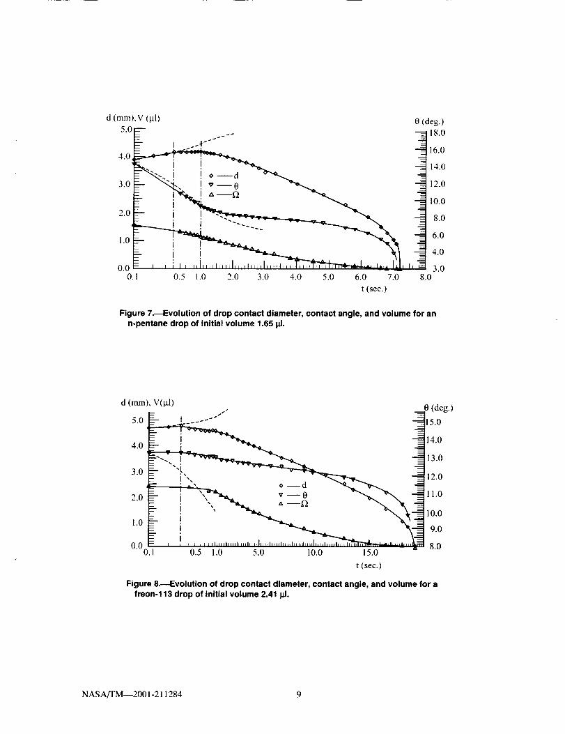
ever, the spreading characteristics of volatile drops are quite different from that of nonvolatile drops. Generally, after
a short initial spreading period, the drops approximately maintain a constant contact-diameter for a brief period, theso-called spreading-evaporation balance stage, followed by a monotonic contraction, referred to as the evaporation-dominant contraction stage. The spreading of an n-pentane drop, a cyclohexane drop, and many others exhibited the
same characteristics. As shown in figure 7, the spreading of the n-pentane drop deviates from the Dodge relation(dish line) after the short initial spreading period and further in time, especially after the thermocapillary convectionoccurs when the spreading-evaporation balance stage ends. Although the evaporation rate of a freon-113 sessile
drop, W,,, = 0.126 lal/sec, is lower than that of an n-pentane sessile drop (Wa, = 0.229 lal/sec), the initial spreadingstage of a freon- 113 drop is much shorter than that of an n-pentane drop. Additionally, no spreading-evaporationbalance-stage is observed, as shown in figure 8. The spreading of the freon-I 13 drop deviates from Dodge's relation
as depicted by the dish line from the very beginning because thermocapillary convection induced by evaporation has
occurred. Evolutions of contact angle and volume for an n-pentane drop with an initial volume of 1.65 _tl and for a
freon-I 13 drop with an initial volume of 2.41 _1 are plotted in figures 7 and 8, respectively.
Because the flow visualization was conducted simultaneously with the measurements of the spreading anddynamic contact angle, the effects of thermocapillary convection in a volatile drop on the spreading process areclearly shown.
CONCLUSIONS
The hybrid optical system consisting of reflection-refracted shadowgraphy and top-view photography is aunique technique for the measurements of spreading, instantaneous dynamic contact-angle, and volume time-historyof a volatile drop on a nontransparent substrate. The merits of this technique are:
1. Because of nontransparency of the substrate and the spherical cap shape of the sessile drop, reflection-
refracted shadowgraphy can be utilized for the visualization study of internal flow in volatile drops. Thetechnique is not suitable for the study of volatile-liquid pools that have a flat interface.
2. The instantaneous drop size, including the contact diameter, contact angle, and drop volume can be accu-
rately determined through the top-view photograph of the drop and its corresponding shadowgraphic image,which are synchronously recorded.
3. The comprehensive information of an evaporating drop on a nontransparent substrate, including the localcontact angle along the periphery of the drop, the instability of the three-phase contact line, and the deforma-tion of the drop shape, can be obtained and analyzed.
4. The effects of thermocapillary convective flow, induced by evaporation, on the spreading of volatile dropscan be accurately investigated.
NASA/'FM--2001-211284 4
REFERENCES
1. N.ZhangandW.J.Yang,MicrostructureofFlowinsideMinuteDropsEvaporatingonaSurface,ASME Jour-ha! of Heat Transfer, Vol. 105, pp. 908-910, 1983.
2. N. Zhang and W.J. Yang, Visualization of Evaporative Convection in Minute Drops by Laser Shadowgraphy,Rev. Sci. lnstrum., Vol. 54, pp. 93-96, 1983.
3. W. Merzkirch, Flow Visualization. Academic Press, New York, 1974.
4. D.F. Chao and N. Zhang, Effects of Evaporation and Thermocapillary Convection on Spreading and ContactAngle of Volatile Droplets, J. of Thermophysics and Heat Transfer, (in print), 2001.
5. N. Zhang and W.J. Yang, Natural Convection in Evaporating Minute Drops, ASME Journal of Heat Transfer.
Vol. 104, pp. 656-662, 1982.6. N. Zhang and D.F. Chao, Effects of Evaporation/Condensation on Spreading and Contact Angle of a Volatile
Drop, Heat Transfer Science and Technology 2000, (edited by B.-X. Wang), higher Education Press, Beijing,pp. 367-372, 2000.
7. C. Allain, D. Ausserre and F. Rondelez, A New Method for Contact-angle Measurements of Sessile Drops,
J. Colloid Intelface Sci., Vol. 107, pp. 5-13, 1985.8. F.T. Dodge, The Spreading of Liquid Droplets on Solid Surfaces, J. Colloid Interface Sci., Vol. 121,
pp. 154-160, 1988.
White light beam
O CCD camera I
Monitor I [ Monitor II_
Laser J .eamsplitterII LVide°printe:
eams 'itter'' i j_-_J - Video recorder I__
Beam splitter I!!-[-_- J',T-_/J-- ] ............... c]D _deo recorder IIJ-
Sessile liquid drop _ I
t _,", _ ...... [ _ CCD camera II
Aluminized glass plate ,,/: _,_, w
"___ _ Screen
d
Figure 1.------Schematicof a hybrid optical system consisting of laser reflection-refracted shedowgraphyand direct photography.
NASA/TM--2001-211284 5
Refracted ray that forms outer
fringe of the shadowgraphic, image Parallel beams
f
Figure 2._Optical path at sessiledrop edge.
11 u,u, i
(a) top-view photograph (b) reflection-refracted shadowgraph
Figure 3. Typical instant top-view photograph of a silicone-oil (50 cSt.) sessile dropand its correspondingreflection-reflectedshadowgraph.
NASA/TM--2001-211284 6

(a) (b)
20 Inln
(c)
Figure 4_lnstant reflection-refracted shadowgraphs of (a) freon-113, (b) n-pentane, and(c) ethanol drops evaporating on an aluminized glass plate in open air.
NASA,rI'M--2001-211284 7
ZO mm J
(a) top-view photograph (b) reflection-refracted shadowgraph
Figure 5._lnstant top-view photograph of a freon-113 drop with aluminum-powder tracer and itscorresponding reflection-refracted shadowgraph.
0 (deg)
5 10 50 100 200 300
t (sec.)
Figure 6.--EvoluUon of drop contact diameter, and contact angle for a silicone oil (50 cSt.)drop of volume 2.2 _xl.
NASA/I'M--2001-211284 8
Form Approved
REPORT DOCUMENTATION PAGE OMB No. 0704-0188
Public reporting burden for this collection of information is estimated to average 1 hour per response, including the time for rewewmg instructions, searching existing data sources.
gathering and maintaining the data needed, and completing and reviewing the collection of information. Send comments regarding this burden estimate or any other aspect of 'this
collection of information, including suggestions for reducing this burden, to Washington Headquaders Services. Directorate for Information Operations and Reports, 1215 Jefferson
Davis Highway, Suite 1204. Arlington. VA 22202-4302, and to the Office of Management and Budget. Paperwork Reduction Project (0704-0188), Washington. DC 20503
1. AGENCY USE ONLY (Leave blank) 2. REPORT DATE 3. REPORT TYPE AND DATES COVERED
November 2001 Technical Memorandum
4. TITLE AND SUBTITLE
Flow Visualization in Evaporating Liquid Drops and Measurement
of Dynamic Contact Angles and Spreading Rate
6. AUTHOR(S)
Nengli Zhang and David F. Chao
7. PERFORMING ORGANIZATION NAME(S) AND ADDRESS(ES)
National Aeronautics and Space Administration
John H. Glenn Research Center at Lewis Field
Cleveland, Ohio 44135-3191
9. SPONSORING/MONITORING AGENCY NAME(S) AND ADDRESS(ES)
National Aeronautics and Space Administration
Washington, DC 20546-0001
5. FUNDING NUMBERS
WU-101-53--00-00
8. PERFORMING ORGANIZATIONREPORT NUMBER
E-13084
10. SPONSORING/MONITORING
AGENCY REPORT NUMBER
NASA TM--2001-211284
11. SUPPLEMENTARY NOTES
Prepared for the 2001 International Mechanical Engineering Congress and Exposition sponsored by the American Society
of Mechanical Engineers, New York City, New York, November 11-16. 2001. Nengli Zhang, Ohio Aerospace Institute,
22800 Cedar Point Road, Brook Park, Ohio 44142, and David E Chao, NASA Glenn Research Center. Responsible
person, David E Chao, organization code 6712.216--433-8320.
12a. DISTRIBUTION/AVAILABILITY STATEMENT
Unclassified - Unlimited
Subject Category: 34 Distribution: Nonstandard
Available electronically, at htto://_ltrs.t,,rc.nasa._o_,, " _ _ _'/Ct,TRS,
This publication is available from the NASA Center for AeroSpace Information, 301_21_)390.
12b. DISTRIBUTION CODE
13. ABSTRACT (Maximum 200 words)
A new hybrid optical system, consisting of reflection-refracted shadowgraphy and top-view photography, is used to
visualize flow phenomena and simultaneously measure the spreading and instant dynamic contact angle in a volatile-
liquid drop on a nontransparent substrate. Themocapillary convection in the drop, induced by evaporation, and the drop
real-time profile data are synchronously recorded by video recording systems. Experimental results obtained from this
unique technique clearly reveal that thermocapillary convection strongly affects the spreading process and the character-
istics of dynamic contact angle of the drop. Comprehensive information of a sessile drop, including the local contact
angle along the periphery, the instability of the three-phase contact line, and the deformation of the drop shape is
obtained and analyzed.
14. SUBJECT TERMS
Thermocapillary convection; Dynamic contact angles; Spreading;
Nontransparent substrate
17. SECURITY CLASSIFICATIONOF REPORT
Unclassified
NSN 7540-01-280-5500
18. SECURITY CLASSIFICATION
OF THIS PAGE
Unclassified
19. SECURITY CLASSIFICATIONOF ABSTRACT
Unclassified
15. NUMBER OF PAGES
15
16. PRICE CODE
20. LIMITATION OF ABSTRACT
Standard Form 298 (Rev. 2-89)
Prescdbed by ANSI Std. Z39-1B298-102
d (mm),V (pl)5.0
4.0
3.0
2.0
1.0
0.00,
0 (deg.)----- ,° _ 18.0
16.0I , 14.0
"_". ! '_ --0 _ 12.0
- __.--" _ 1o.o_---- I -..- i J "'--. 8.o--- I .... 6.0---- i J
= , , ;i,,,,I,,,,i,,,,I .... _.... I .... _...... .- ,,-,,,l_ ,,I, 3.00.5 1.0 2.0 3.0 4.0 5.0 6.0 7.0 8.0
t (sec.)
Figure 7.--Evolution of drop contact diameter, contact angle, and volume for ann-pentane drop of initial volume 1.65 I_1.
d (mm), V(_tl) ,- __0 (deg.)
5.0 t ..... -" 15.0
14.0
I 71 o
g ,: • _ \v_ 'o-o1.0 _ 9.00.0 8.0
0.1 0.5 1.0 5.0 10.0 15.0
t (sec.)
Figure 8.---Evolution of drop contact diameter, contact angle, and volume for afreon-113 drop of Initial volume 2.41 _.
NASA/'I'M---2001-211284 9