Embed Size (px)
Citation preview

FLOW RATE STATIC BALANCINGValves for radiators
TECHNICAL FOCUS
The valves for radiators equipped with pre-setting device play a very important role in balancing the heating systems circuits. In fact they allow, by means of static balancing, to adjust each heating body with the right flow rate and thus to obtain the right amount of heat. This performance, as further detailed below, can not be obtained with conventional valves.
They are adjusted operating on a knob that controls the movement of an obturator.Piezometric connections are placed upstream of the obturator, on a Venturi section. Therefore, the obturator position does not affect the flow rate determination.
They are adjusted operating on a stem that controls a ball obturator.The flow rates can be directly checked on the flowmeter installed on the device.It is not necessary to calculate the setting position at the design stage.
They are adjusted operating on a knob that controls the movement of an obturator.The piezometric connections are located upstream and downstream of the obturator. To determine the flow rate, it is necessary to know the obturator adjustment position.
They are adjusted acting on the locking nut that changes the medium flow cross section, creating a "throttle", specifically, a medium flow resistance.It is not possible to determine the actual flow rate by acting directly on the valve.
STATIC BALANCING
Fixed orifice manual valve
Manual valve with flow meter
Manual valve with variable orifice
Pre-settable radiator valves
Balancing part 3
RT
Adjustment valve
Generic secondary circuit
Secondary circuit with radiators
Secondary circuit with radiators
Thermostatic valve
Thermostatic valve with pre-setting
Lockshield valve
Balancing valve
RT
Adjustment valve
Generic secondary circuit
Secondary circuit with radiators
Secondary circuit with radiators
Thermostatic valve
Thermostatic valve with pre-setting
Lockshield valve
Balancing valve
RT
Adjustment valve
Generic secondary circuit
Secondary circuit with radiators
Secondary circuit with radiators
Thermostatic valve
Thermostatic valve with pre-setting
Lockshield valve
Balancing valve
SECONDARY CIRCUIT WITH RADIATORS
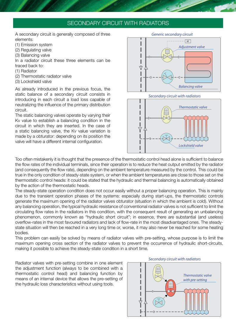
A secondary circuit is generally composed of three elements: (1) Emission system (2) Regulating valve(3) Balancing valveIn a radiator circuit these three elements can be traced back to: (1) Radiator(2) Thermostatic radiator valve(3) Lockshield valve
As already introduced in the previous focus, the static balance of a secondary circuit consists in introducing in each circuit a load loss capable of neutralizing the influence of the primary distribution circuit.The static balancing valves operate by varying their Kv value to establish a balancing condition in the circuit in which they are inserted. In the case of a static balancing valve, the Kv value variation is made by a obturator: depending on its position the valve will have a different internal configuration.
Too often mistakenly it is thought that the presence of the thermostatic control head alone is sufficient to balance the flow rates of the individual terminals, since their operation is to reduce the heat output emitted by the radiator (and consequently the flow rate), depending on the ambient temperature measured by the control. This could be true in the only condition of steady-state system, or when the ambient temperatures are close to those set on the thermostatic control heads: it could be stated that the hydraulic and thermal balancing is automatically obtained by the action of the thermostatic heads.The steady-state operation condition does not occur easily without a proper balancing operation. This is mainly due to the transient operation phases of the systems: especially during start-ups, the thermostatic controls generate the maximum opening of the radiator valves obturator (situation in which the ambient is cold). Without any balancing operation, the typical hydraulic resistance of conventional radiator valves is not sufficient to limit the circulating flow rates in the radiators in this condition, with the consequent result of generating an unbalancing phenomenon, commonly known as “hydraulic short circuit”; in essence, there are substantial (and useless) overflow-rates in the most favoured radiators and lack of flow-rate in the most disadvantaged ones. The steady-state situation will then be reached in a very long time or, worse, it may also never be reached for some heating bodies.This problem can easily be solved by means of radiator valves with pre-setting, whose purpose is to limit the maximum opening cross section of the radiator valves to prevent the occurrence of hydraulic short-circuits, making it possible to achieve the steady-state condition in a short time.
Radiator valves with pre-setting combine in one element the adjustment function (always to be combined with a thermostatic control head) and balancing function by means of an internal device that allows the pre-setting of the hydraulic loss characteristics without using tools.

Specific passage cross sections can be selected by means of the locking nut, in order to generate the required resistance to the motion of the medium.Each cross section equates to a specific Kv value to create the head loss corresponding to a given setting position on a graduated scale.
The Kv value is varied by modifying the passage cross section through fixed windows corresponding to discrete values.
Pre-setting valves for heating bodies
As for classic balancing valves, Kv values are usually reported on a diagram:
Pre-setting device Flat development
Pressure drop diagram for pre-setting valve with thermostatic control head
Flow
rat
e [m
3 /h]
Dp
[kP
a]
Setting Position
Kv[m3/h]

Start-up phaseTraditional and lockshield valve with setting
To illustrate the topic, it is reasonable to ignore the load losses generated by radiators (generally negligible) and by the distribution pipes (negligible for short sections). It is required to operate a 1800 W power radiator with thermal head ΔT = 15°C, assuming to design it with 2K proportional bandwidth, i.e. using the design flow rate, in this case equal to 103 l/h when there is a 2°C deviation from the desired ambient temperature. At the ends of the circuit the head should be 10 kPa, typical minimum value for valves with thermostatic controls.
This excess flow rate represents a strong hydraulic unbalancing, which clearly highlights the reason for which the “hydraulic short circuit” problems described occur and the reason for the need to intervene on the radiator circuit balancing.
The available head H (10 kPa) is equal to the sum of the load losses of the radiator valve (ΔPVT) and of the lockshield valve (ΔPDET). Explaining these load losses according to the formula that binds the flow rate, the flow coefficient and the load loss (see box below) it is possible to calculate the G2K flow rate, known the Kv2K (0,57 m3/h) values of the traditional radiator valve with thermostatic control head installed, the KvTA (2,42 m3/h) value of the fully opened lockshield valve.
The elements that make up a radiator circuit that controls the flow rate (limiting circuit) are essentially the distribution pipes, a radiator valve with thermostatic control head, a radiator, a lockshield valve.
With only thermostatic control head, it is not possible to obtain the design flow rate for 2K design deviation.
START-UP PHASE
The critical condition originates in the transient phase of start-up with cold system when the thermostatic control head generates the maximum opening of the obturator. In this condition the radiator valve characteristic is equal to KvMAX = 2,29 m3/h. With this value the circulating flow rate at start-up can be estimated with the same relationship that binds the flow rate, flow coefficient and load loss (see box above):
Thermostatic radiator valve and lockshield valve without setting
9,5
0,5
5,3
4,7
9,8
0,2
9,5
0,5[kPa]
[kPa]
[kPa]
[kPa]
4
6 [kPa]
TRADITIONAL LOCKSHIELD VALVE WITHOUT SETTING
VALVE WITH PRE-SETTING LOCKSHIELD VALVE WITHOUT
TRADITIONAL LOCKSHIELD VALVE WITH SETTING
175 l/h+ 70%
110 l/h+ 6%
526 l/h+ 410%
170 l/h+ 64%
Kv2K= 0,57
KvMAX= 2,29
Kv2K= 0,35
KvMAX= 0,55
10 kPa
10 kPa
10 kPa 115 l/h+ 11%
Kv2K= 0,57
10 kPa
10 kPa
POS. 4
POS. 4
1800 W
1800 W
1800 W
1/2 turn
1800 W
1800 W
9,5
0,5
5,3
4,7
9,8
0,2
9,5
0,5[kPa]
[kPa]
[kPa]
[kPa]
4
6 [kPa]
TRADITIONAL LOCKSHIELD VALVE WITHOUT SETTING
VALVE WITH PRE-SETTING LOCKSHIELD VALVE WITHOUT
TRADITIONAL LOCKSHIELD VALVE WITH SETTING
175 l/h+ 70%
110 l/h+ 6%
526 l/h+ 410%
170 l/h+ 64%
Kv2K= 0,57
KvMAX= 2,29
Kv2K= 0,35
KvMAX= 0,55
10 kPa
10 kPa
10 kPa 115 l/h+ 11%
Kv2K= 0,57
10 kPa
10 kPa
POS. 4
POS. 4
1800 W
1800 W
1800 W
1/2 turn
1800 W
1800 W
Dimensioning to 2KTraditional and lockshield valve without setting
G2K=175 l/h + 70% compared to the design �ow rate
H = 10-4 ⋅
H = ΔPVT + ΔPDET
+ 10-4 ⋅
+
2 ( )
G2K Kv2K
G2K = 100 ⋅
⋅ √ H
-0,5 ( )
1
Kv 22K
1
Kv 2RT
( ) G2K KvRT
GMAX=526 l/h +410% compared to the design �ow rate
+
GMAX = 100 ⋅
⋅ √ H
-0,5 ( )
1
Kv 2MAX
1
Kv 2RT
BALANCING OF SECONDARY CIRCUIT WITH RADIATORS
G = 100 ⋅ Kv ⋅ √ ΔP
G: [l/h]Kv: [m3/h]ΔP: [kPa]
Relationship between flow rate, flow coefficient and load loss

Therefore, knowing the Kv2K, (4) value for the selected adjustment position, it is possible to calculate the effective flow rate at the 2K deviation, always according to the relationship:
Thanks to the balancing carried out with the pre-setting, in the proportional 2K bandwidth design condition, it is possible to actually obtain a flow rate value close to the design value.
During the transient start-up phase, the maximum opening cross section is the result of the pre-setting position set.Therefore, at the adjustment position 4, the KvMAX (4) value equal to 0,55 m3/h limits the circulating flow rate in the radiator to a value equal to:
Thanks to the limitation introduced, the excesses over-flow rates in the most favoured radiators can efficiently be eliminated.The starting phases are therefore shorter and uniform for all the radiators of the systems, which are therefore in the best condition to effectively reach the steady-state operating condition.
Through the formula or simply through the graph, the pre-setting position of the valve is obtained: considering the available head H = 10 kPa (for pre-setting it is reasonable to neglect the load loads of the fully open lockshield valve) and the design flow rate GPR = 103 l/h, the adjustment position 4 is obtained, closest to the point found.In this position the valve has a value of Kv2K,(4) = 0,35 m3/h.
START-UP PHASE
9,5
0,5
5,3
4,7
9,8
0,2
9,5
0,5[kPa]
[kPa]
[kPa]
[kPa]
4
6 [kPa]
TRADITIONAL LOCKSHIELD VALVE WITHOUT SETTING
VALVE WITH PRE-SETTING LOCKSHIELD VALVE WITHOUT
TRADITIONAL LOCKSHIELD VALVE WITH SETTING
175 l/h+ 70%
110 l/h+ 6%
526 l/h+ 410%
170 l/h+ 64%
Kv2K= 0,57
KvMAX= 2,29
Kv2K= 0,35
KvMAX= 0,55
10 kPa
10 kPa
10 kPa 115 l/h+ 11%
Kv2K= 0,57
10 kPa
10 kPa
POS. 4
POS. 4
1800 W
1800 W
1800 W
1/2 turn
1800 W
1800 W
9,5
0,5
5,3
4,7
9,8
0,2
9,5
0,5[kPa]
[kPa]
[kPa]
[kPa]
4
6 [kPa]
TRADITIONAL LOCKSHIELD VALVE WITHOUT SETTING
VALVE WITH PRE-SETTING LOCKSHIELD VALVE WITHOUT
TRADITIONAL LOCKSHIELD VALVE WITH SETTING
175 l/h+ 70%
110 l/h+ 6%
526 l/h+ 410%
170 l/h+ 64%
Kv2K= 0,57
KvMAX= 2,29
Kv2K= 0,35
KvMAX= 0,55
10 kPa
10 kPa
10 kPa 115 l/h+ 11%
Kv2K= 0,57
10 kPa
10 kPa
POS. 4
POS. 4
1800 W
1800 W
1800 W
1/2 turn
1800 W
1800 W
Dimensioning to 2KValve with pre-setting and lockshield valve without setting
Calculation using the graph: Flow rate-ΔPCalculation using the formulas
Dimensioning to 2KValve with pre-setting and lockshield valve without setting
G1 = F ⋅ G = 1,17 ⋅ 300 = 350 l/h
G2K=110 l/h +6% compared to the design �ow rate
+
G2K = 100 ⋅
⋅ √ H
-0,5 ( )
1
Kv 22K,(4)
1
Kv 2TA
GMAX=170 l/h +64% compared to the design �ow rate
+
GMAX = 100 ⋅
⋅ √ H
-0,5 ( )
1
Kv 2MAX,(4)
1
Kv 2TA
Thermostatic radiator valvewith pre-setting and lockshield valve without setting
Flow
rat
e [m
3 /h]
Dp
[kP
a]
Setting Position
Kv[m3/h]

WE RESERVE THE RIGHT TO MAKE CHANGES AND IMPROVEMENTS TO THE PRODUCTS AND RELATED DATA IN THIS PUBLICATION, AT ANY TIME AND
WITHOUT PRIOR NOTICE.
0851
817G
B
Visit Caleffi on YouTubeyoutube/CaleffiVideoProjects
REFERENCE DOCUMENT: TECH. BROCHURE 01195BROCHURE 01034
Caleffi S.p.A. · S.R. 229 n. 25 · 28010 Fontaneto d’Agogna (NO) · ItalyTel. +39 0322 8491 · Fax +39 0322 863723
[email protected] · www.caleffi.com · © Copyright 2017 Caleffi
It is necessary first to establish the ΔPDET theoretical load loss that the lockshield valve must generate as the difference between the available head H and the radiator valve load loss at the GPR design flow rate:
With this value, the graph is used to search the number of revolutions to be made on the lockshield valve, in this case 1/2, which corresponds to a Kv1/2 value of 0,47 m3/h (value calculated from the graph). The actual flow rate with 2K bandwidth is therefore calculated as:
The balancing operation of heating bodies equipped with conventional valves can be carried out by means of appropriate setting of the lockshield valve. From a hydraulic point of view, since the lockshield valve represents an additional load loss in series to the radiator valve, it is possible to adjust its Kv value in order to obtain the desired flow rate in the design conditions. However, this operation has a series of limitations and disadvantages (see lockshield valve box already done):• the lockshield valves do not have graduated scales and therefore the curves refer to the number of revolutions
to be made with a Allen key from the "all closed" position.• the setting operations are complicated and subject to errors;• during testing or abnormal operation of the system, the setting operations checks are demanding;• the setting “memory” is lost during maintenance work.
9,5
0,5
5,3
4,7
9,8
0,2
9,5
0,5[kPa]
[kPa]
[kPa]
[kPa]
4
6 [kPa]
TRADITIONAL LOCKSHIELD VALVE WITHOUT SETTING
VALVE WITH PRE-SETTING LOCKSHIELD VALVE WITHOUT
TRADITIONAL LOCKSHIELD VALVE WITH SETTING
175 l/h+ 70%
110 l/h+ 6%
526 l/h+ 410%
170 l/h+ 64%
Kv2K= 0,57
KvMAX= 2,29
Kv2K= 0,35
KvMAX= 0,55
10 kPa
10 kPa
10 kPa 115 l/h+ 11%
Kv2K= 0,57
10 kPa
10 kPa
POS. 4
POS. 4
1800 W
1800 W
1800 W
1/2 turn
1800 W
1800 W
Dimensioning to 2KTraditional and lockshield valve with setting
GMAX=115 l/h +11% compared to the design �ow rate
+
G2K = 100 ⋅
⋅ √ H
-0,5 ( )
1
Kv 22K
1
Kv 21/2
ΔPDET = H - ΔPV
= 10 - 3,3 = 6,7 kPa ΔPDET = H - 10-4 ⋅
2 ( ) GPR
Kv 2K
GMAX=115 l/h +11% compared to the design �ow rate
+
G2K = 100 ⋅
⋅ √ H
-0,5 ( )
1
Kv 22K
1
Kv 21/2
ΔPDET = H - ΔPV
= 10 - 3,3 = 6,7 kPa ΔPDET = H - 10-4 ⋅
2 ( ) GPR
Kv 2K
For these difficulties and disadvantages, the lockshield valves are often not adjusted but act only as shut-off valves for maintenance of the radiator.
Thermostatic radiator valve and lockshield valve with setting
The adjustment position is obtained knowing the design flow rate that must flow through the radiator and the load loss that the lockshield valve must introduce into the secondary circuit to make it balanced.
Pre-setting of heating bodies with lockshield valve
50 100
200
2010 500
1000
2000
5000
2000
1000
500
200
100
50
20
10
Δp (mm w.g.) Δp (kPa)
Angled connections lockshield valve elbow (1/2”)Lockshield valve type cross section
Allen key
Adjustment screw
Obturator
G (l/h)
1/4 1/2 1 2
fully
open
50
20
10
5
2
1
0,5
0,2
0,1
1/2Kv 0,01= 399 l/ h