Embed Size (px)
Citation preview

HEFAT2014
10th
International Conference on Heat Transfer, Fluid Mechanics and Thermodynamics
14 – 26 July 2014
Orlando, Florida
Flow Past A Cylinder With Upstream Splitter Plate
Rajkumar M.R*1,Rijas A.S
1 and Venugopal.G
2.
* Department of Mechanical Engineering, College of Engineering, Trivandrum, Kerala, India
1. Department of Mechanical Engineering, College of Engineering, Trivandrum, Kerala, India
2. Department of Mechanical Engineering, Govt: Rajiv Gandhi Institute of Technology, Kottayam, Kerala, India,
E-mail: [email protected]
ABSTRACT
This paper reports combined experimental and numerical
investigations performed to study the effect of upstream splitter
plate on drag reduction of a circular cylinder. The influence of
spacing between the cylinder and splitter plate (aspect ratio)
and thickness of the splitter plate (thickness ratio) on the flow
characteristics of the cylinder is analyzed and discussed. The
mathematical model governing the problem is numerically
solved using a commercial computational fluid dynamics
package ANSYS 14. The simulations have been carried out for
Re=20,150 and 6×10⁴ so as to cover the laminar regime. In
order to validate the numerical model, experiments are
performed by placing the cylinder along with the splitter plate
in a low speed subsonic wind tunnel.
Keywords: - Reynolds number, aspect ratio, thickness ratio,
coefficient of drag.
NOMENCLATURE
A [m2] Projected area
CD [-] Coefficient of drag
CP [-] Coefficient of pressure
CPC [-] Pressure coefficient at the front stagnation point of
the cylinder
CPS [-] Pressure coefficient at the trailing edge of the
upstream splitter plate
∆CP [-] Difference between CPC and CPS
D [m] Diameter of cylinder
L [m] Length of the plate
P [Pa] Pressure at different point on the surface of the
cylinder.
P∞ [Pa] Free stream pressure
Re [-] Reynolds number
S [m] Spacing between plate and cylinder
T [m] Thickness of plate
U∞ [m/s] Free stream velocity
u [m/s] X-component of velocity at different locations
measured along the Y- direction at the downstream of
the cylinder.
AR [-] Aspect Ratio (S/D)
TR [-] Thickness Ratio (T/D)
Greek Symbols
ρ [kg/m3] Density
ν [m2/s] Kinematic viscosity
θ [degree] Angular position on the surface of the cylinder.
INTRODUCTION
Flow past a circular cylinder has been investigated by
various researchers because of its practical applications in
variety of engineering flows, such as offshore risers, bridge
piers, periscopes, chimneys, towers, masts, stays, cables,
antennae, wires etc. The flow past a cylinder is associated with
very rich vortex dynamics, and different flow patterns are
observed for various regimes of flow. The flow separation on
the surface of the cylinder causes pressure drop in the rear part
of the cylinder, resulting in considerable increase in pressure
drag. Reducing the drag is critically important in many
engineering applications, and different techniques have been
proposed to achieve this goal. Among the different techniques
the most frequently used methods are modification of the shape
of the cylinder or placing additional surfaces in the flow stream
either at the rear or the front of the cylinder.
Alam et al. [1] conducted experiments to study
interaction of fluctuating aerodynamic forces on two circular
cylinders of same diameter arranged in tandem in uniform flow.
The study revealed that the effect of aerodynamic forces on the
downstream cylinder will be significant only when the spacing
between the cylinders is 3 times diameter of the cylinder.
The same authors [2] also studied experimentally the
effect of T-shaped plate placed upstream of tandem cylinders
considered in their earlier studies. They reported that for a tail
length of T-shaped plate in the range 0.7 - 1.00 times the
diameter of the cylinder, there was significant reduction in the
fluid forces acting on the cylinder.
The effect of the splitter plate in the downstream of a
vertical circular cylinder placed in shallow water was studied
experimentally by Akilli et al. [3] .They observed that
significant vortex suppression, when the distance between
cylinder base and leading edge of the plate was kept in the
range of 0-1.75 times the diameter of the cylinder.
Numerical investigation was performed by Hwang et al.
[4] to study drag reduction on a circular cylinder by using two
plates. One plate was placed in the upstream and other in the
downstream of the cylinder along the centreline. The upstream
plate reduces pressure in the vicinity of front stagnation point
of the cylinder with a secondary effect of increasing the base
pressure, while the downstream plate effectively suppresses
vortex shedding in the near wake region by increasing pressure
133
in the rear of the cylinder. They obtained minimum drag if
distance between plates and cylinder were 1.5 and 2.4 times the
diameter of the cylinder for upstream and downstream plates
respectively.
Ali et al. [5] numerically investigated flow over square
cylinder by placing a flat plate horizontally in the downstream.
They identified significant reduction of drag force when the
plate is placed at a distance of 2.3 times side length of the
cylinder. It was also estimated that a total lift cancellation was
possible if a plate of length equal to 0.26 times diameter of the
cylinder is placed at a distance of 5.6 times diameter of the
cylinder. Numerical investigations are performed by Alex et al
[6]to study the effect of flat ground boundary near a cylinder on
the suppression of vortex shedding. The analyses demonstrated
that the presence of plane ground will produce additional
circulation caused by the fluid viscosity with the Venturi effect.
The additional circulation around the body is responsible for
increase in lift force acting on body surface, while the venture
effect is responsible for the decrease in drag force acting on
body surface. Qui et al [7] experimentally investigated, the
characteristics of wind loads acting on a circular cylinder with
attached splitter plates at the front and rear of the cylinder. The
study revealed that vortex shedding from the cylinder can be
suppressed by a splitter plate having length equal to 3 times
diameter of the cylinder in the wake.
From the above literature survey, it can be seen that
many of the previous investigators have focused their attention
on the effect of splitter plate placed either at upstream or
downstream of the cylinder on the drag reduction. However
most of these investigations are numerical. Experimental
investigations relating to the study of the effect of splitter plate
on the drag reduction of a cylinder has not been found else
were in literature. The aim of this work is to experimentally
investigate the effect of upstream splitter plate on the drag
characteristics of a cylinder. Numerical analysis has also been
performed and the numerical results are validated by comparing
with experimental results. The influence of Reynolds number,
aspect ratio and thickness ratio of the splitter plate on the drag
characteristics of the cylinder is analyzed and discussed.
EXPERIMENTAL SETUP
The physical system consists of a cylinder having a
diameter of 100mm with an upstream splitter plate of length
equal to diameter of the cylinder placed upstream of the
cylinder as shown in Figure 1. In the present work the main
emphasis to study the effect of detached upstream splitter plate
on the drag reduction on the cylinder, depending on the AR and
TR, while the flow topology remains unchanged. To achieve
this objective the length of the splitter plate is made equal to
diameter so that the flow past the detached plate is laminar and
the momentum thickness over the splitter plate boundary layer
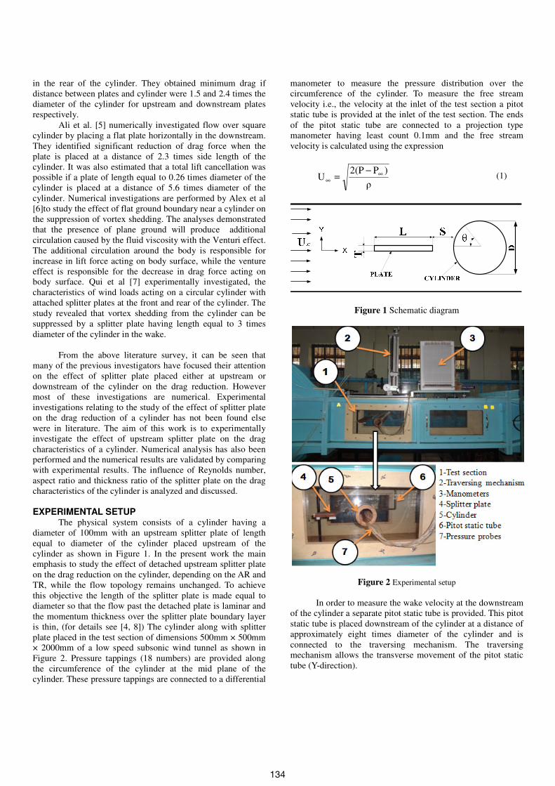
is thin, (for details see [4, 8]) The cylinder along with splitter
plate placed in the test section of dimensions 500mm × 500mm
× 2000mm of a low speed subsonic wind tunnel as shown in
Figure 2. Pressure tappings (18 numbers) are provided along
the circumference of the cylinder at the mid plane of the
cylinder. These pressure tappings are connected to a differential
manometer to measure the pressure distribution over the
circumference of the cylinder. To measure the free stream
velocity i.e., the velocity at the inlet of the test section a pitot
static tube is provided at the inlet of the test section. The ends
of the pitot static tube are connected to a projection type
manometer having least count 0.1mm and the free stream
velocity is calculated using the expression
ρ
)P2(PU ∞
∞
−=
(1)
Figure 1 Schematic diagram
Figure 2 Experimental setup
In order to measure the wake velocity at the downstream
of the cylinder a separate pitot static tube is provided. This pitot
static tube is placed downstream of the cylinder at a distance of
approximately eight times diameter of the cylinder and is
connected to the traversing mechanism. The traversing
mechanism allows the transverse movement of the pitot static
tube (Y-direction).
134

The important dimensionless parameters considered in
this study are
Reynolds number, ν
DURe ∞
= (2)
Coefficient of pressure, 2
21PρU
PPC
∞
∞−
= (3)
Coefficient of drag,
Based on wake velocity, ∫ −=
∞
∞− ∞∞
)dyU
u(1
U
u2CD (4)
Based on pressure distribution, ∫−=
2π
0PD θdθ cosC
2
1C (5)
NUMERICAL ANALYSIS
The mathematical modelling governing the problem is
numerically solved in a two dimensional computational domain
using commercially available computational fluid dynamics
package ANSYS FLUENT 14 [9]. The flow is assumed to be
incompressible and laminar. The simulation have been
performed for steady (Re=20) and unsteady (Re=150 & 6×10⁴)
cases. The computational domain consists of cylinder, upstream
splitter plate and the region surrounding them. The size of the
computational domain has been fixed based on the results of
the earliest studies[10]. The governing equation of flow
pertinent to this problem can be seen in Kundu et al. [11]
A. Boundary conditions and grid
No slip boundary conditions are employed on surfaces
of cylinder and plate. At inlet, top and bottom boundaries of the
domain, the velocity inlet (free stream velocity) boundary
condition is specified, whereas pressure outlet condition is
given at exit. The computational domain is discretised using
structured non-uniform quadrilateral cells. Fine grids were used
in the regions near the cylinder and plate so as to capture the
gradient of the field variables. In order to arrive at an optimum
grid, a grid sensitivity study has been conducted, at Re=20
(steady) as shown in Table1.The results are found to be
insensitive to the grid beyond the one with beyond the one with
21500 cells consisting of 43330 faces and 21830 nodes. The
final computational domain along with grid used for numerical
simulation is shown in Figure 3.
Table 1 Grid Independence study (Re=20,AR=0.01, TR=1)
No of cells Maximum coefficient of drag CD
13000 1.30418
21500 1.28377
32000 1.28307
B. Numerical solution procedure
In the present computation the steady and transient
solver options available in the FLUENT solver has been used
for solving the governing partial differential equations for
steady and unsteady cases respectively. Pressure based option
with second order upwind discretization scheme has been
selected for the present computation. The coupling between
velocity and pressure is resolved by selecting the SIMPLE
(Semi-implicit method for pressure linked equations) [12]
algorithm. Since the equations are non linear the solution has to
be progressed in a controlled manner. This is achieved by using
relaxation factors. The under relaxation factors used in the
present study are 0.3 for pressure and 0.7 for momentum.
Convergence of the solution is checked by examining the
residues of discretised conservation equations of mass and
momentum. For unsteady case (Re=150) time step size is
specified as 0.01s. The iteration is terminated only when the
maximum of all the residues reaches less than 1×10⁻⁶
to assure
conservation of quantities.
Figure 3 Computational domain and grid
RESULTS AND DISCUSSION
Experiments are conducted for Re=6×10⁴ , aspect ratio 0.1,
thickness ratio 0.2.The wake velocity at the downstream of the
cylinder was measured by using pitot static tube connected to
the differential manometer. Knowing the wake velocity
distribution, drag force experienced by the cylinder was
calculated by using equation (4). In order to check the validity
of the above methodology the drag, based on the pressure
distribution on the surface of the cylinder, by using equation (5)
the coefficient of drag was calculated. These two results found
to agree well as shown in Table2.
To check the validity of the proposed numerical
methodology in solving this problem, numerical simulations
were conducted for the same conditions as that of experiments.
The comparison of the drag force experienced by the cylinder
depicted in Table2 shows reasonably good agreement. The
deviation in the values due to the experimental uncertainties
which are inherent to any experimental setup. This comparison
exercise shows the efficacy of the proposed numerical
methodology in solving this type of problem. Due to
experimental limitations, further numerical simulations were
performed for Re=20(steady flow) and Re=150(unsteady flow),
aspect ratio (0.1 - 25) and thickness ratio (0.01-9).
135
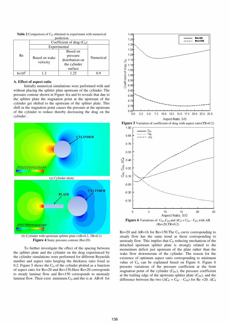
Table 2 Comparison of CD obtained in experiment with numerical
prediction
Re
Coefficient of drag (CD)
Experimental
Numerical Based on wake
velocity
Based on
pressure
distribution on
the cylinder
surface
6×10⁴ 1.2 1.25 0.9
A. Effect of aspect ratio
Initially numerical simulations were performed with and
without placing the splitter plate upstream of the cylinder. The
pressure contour shown in Figure 4(a and b) reveals that due to
the splitter plate the stagnation point at the upstream of the
cylinder get shifted to the upstream of the splitter plate. This
shift in the stagnation point causes the pressure at the upstream
of the cylinder to reduce thereby decreasing the drag on the
cylinder .
(a) Cylinder alone
(b) Cylinder with upstream splitter plate (AR=0.2, TR=0.2)
Figure 4 Static pressure contour (Re=20)
To further investigate the effect of the spacing between
the splitter plate and the cylinder on the drag experienced by
the cylinder simulations were performed for different Reynolds
number and aspect ratio keeping the thickness ratio fixed as
0.2. Figure 5 shows the CD of the cylinder plotted as a function
of aspect ratio for Re=20 and Re=150.Here Re=20 corresponds
to steady laminar flow and Re=150 corresponds to unsteady
laminar flow. Their exist minimum CD and this is at AR=8 for
Figure 5 Variation of coefficient of drag with aspect ratio(TR=0.2)
Figure 6 Variations of CPC,CPS and ∆CP = CPC - CPS with AR
(Re=20,TR=0.2)
Re=20 and AR=16 for Re=150.The CD curve corresponding to
steady flow has the same trend as those corresponding to
unsteady flow. This implies that CD reducing mechanism of the
detached upstream splitter plate is strongly related to the
momentum deficit just upstream of the plate rather than the
wake flow downstream of the cylinder. The reason for the
existence of optimum aspect ratio corresponding to minimum
value of CD can be explained based on Figure 6. Figure 6
presents variations of the pressure coefficient at the front
stagnation point of the cylinder (CPC), the pressure coefficient
at the trailing edge of the upstream splitter plate (CPS), and the
difference between the two (∆CP = CPC - CPS) for Re =20. ∆CP
136
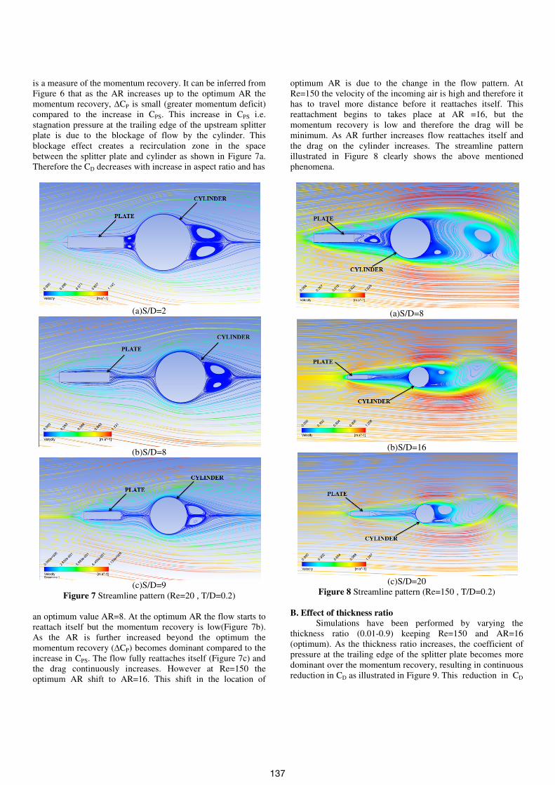
is a measure of the momentum recovery. It can be inferred from
Figure 6 that as the AR increases up to the optimum AR the
momentum recovery, ∆CP is small (greater momentum deficit)
compared to the increase in CPS. This increase in CPS i.e.
stagnation pressure at the trailing edge of the upstream splitter
plate is due to the blockage of flow by the cylinder. This
blockage effect creates a recirculation zone in the space
between the splitter plate and cylinder as shown in Figure 7a.
Therefore the CD decreases with increase in aspect ratio and has
(a)S/D=2
(b)S/D=8
(c)S/D=9
Figure 7 Streamline pattern (Re=20 , T/D=0.2)
an optimum value AR=8. At the optimum AR the flow starts to
reattach itself but the momentum recovery is low(Figure 7b).
As the AR is further increased beyond the optimum the
momentum recovery (∆CP) becomes dominant compared to the
increase in CPS. The flow fully reattaches itself (Figure 7c) and
the drag continuously increases. However at Re=150 the
optimum AR shift to AR=16. This shift in the location of
optimum AR is due to the change in the flow pattern. At
Re=150 the velocity of the incoming air is high and therefore it
has to travel more distance before it reattaches itself. This
reattachment begins to takes place at AR =16, but the
momentum recovery is low and therefore the drag will be
minimum. As AR further increases flow reattaches itself and
the drag on the cylinder increases. The streamline pattern
illustrated in Figure 8 clearly shows the above mentioned
phenomena.
(a)S/D=8
(b)S/D=16
(c)S/D=20
Figure 8 Streamline pattern (Re=150 , T/D=0.2)
B. Effect of thickness ratio
Simulations have been performed by varying the
thickness ratio (0.01-0.9) keeping Re=150 and AR=16
(optimum). As the thickness ratio increases, the coefficient of
pressure at the trailing edge of the splitter plate becomes more
dominant over the momentum recovery, resulting in continuous
reduction in CD as illustrated in Figure 9. This reduction in CD
137

Figure 9 Variation of coefficient of drag with thickness
ratio (Re=150,S/D=16)
(a)T/D=0.3
(b)T/D=0.7
(b)T/D=0.9
Figure 10 Streamline pattern (Re=150, S/D=16)
is due to the increase in the strength of the vortex with increase
in thickness ratio as shown in figure 10a and b. Furthermore its
worth to mention here that as the TR is increased beyond 0.7
vortex shedding takes place in the space between splitter plate
and the cylinder Figure 10c, and the cylinder experience a drag
in the opposite direction.
CONCLUSION
The effect of upstream splitter plate on the drag
reduction of a circular cylinder has been investigated
experimentally and numerically. Experimentally measured CD
were found to agree well with numerical results there by
establishing the proposed numerical methodology. From the
results it was observed that there exists an optimum AR at
which the drag experienced by the cylinder was minimum. The
location of optimum aspect ratio is different for steady Re=20
and unsteady Re=150. This is because the fluid has to travel
more distance before it reattach itself. The increase in thickness
ratio of the splitter plate continuously decreases the drag up to
0.07 due to the increase in the stagnation pressure at the trailing
edge of the splitter plate. As the thickness ratio increases
beyond 0.07 the cylinder experience a drag in the opposite
direction due to the vortex shedding in the space between
splitter plate and cylinder. The thickness ratio of the splitter
plate continuously decreases drag up to 0.7 and thereafter the
cylinder experiences a drag in the opposite direction.
REFERENCES
[1] Md. Mahbub Alam, M. Moriya, K. Takai, H. Sakamoto.
Fluctuating fluid forces acting on two circular cylinders in a
tandem arrangement at a subcritical Reynolds number. Journal of
Wind Engineering and Industrial Aerodynamics, 91: 139–154
,2003A.
[2] Md. Mahbub Alam, H. Sakamoto, Y. Zhoua. Effect of a T-shaped
plate on reduction in fluid forces on two tandem cylinders in a
cross-flow. Journal of Wind Engineering and Industrial
Aerodynamics, 94:525–551, 2006.
[3] Huseyin Akilli, Besir Sahin, N. Filiz Tumen. Suppression of
vortex shedding of circular cylinder in shallow water by a splitter
plate. Flow Measurement and Instrumentation , 16: 211–
219,2005.
[4] Jong-Yeon Hwang, Kyung-Soo Yang, Drag reduction on a
circular cylinder using dual detached splitter plates. Journal of
Wind Engineering and Industrial Aerodynamics ,95: 551–
564,2005.
[5] Mohamed Sukri Mat Ali ,Con J. Doolan. Vincent Wheatley, Low
Reynolds number flow over a square cylinder with a detached flat
plate. International Journal of Heat and Fluid Flow , 36:133–
141,2012.
[6] Alex Mendonca Bimbato , Luiz Antonio Alcantara Pereira ,
Miguel Hiroo Hirata , Suppression of vortex shedding on a bluff
body. Journal of Wind Engineering and Industrial Aerodynamics,
121: 16–28 ,2013.
[7] Y.Qiu , Y.Sun , Y.Wu, Y.Tamura. Effects of splitter plates and
Reynolds number on the aerodynamic loads acting on a circular
cylinder. Journal of Wind Engineering and Industrial
Aerodynamics, 127: 40–50 ,2014.
[8] H.Schlichting, K.Gersten ,Boundary Layer theory, Springer-
Verlag, 2000.
138

[9] ANSYS FLUENT 14,275 Technology Drive , Canonburg.
[10] https://confluence.cornell.edu/display/SIMULATION/FLUENT+
Learning+Modules
[11] Pijush K.Kundu, Ira M.Cohen, Fluid Mechanics, Academic
Press,79-99,2002.
[12] S.V Patankar, Numerical Heat Transfer and Fluid Flow, McGraw
Hill Book Company, Washington, 126-131,1980.
139