Embed Size (px)
Citation preview

Flow Meter Reference Design
Document Number: DRM138Rev. 0, 12/2012

Flow Meter Reference Design, Rev. 0, 12/2012
2 Freescale Semiconductor, Inc.

Contents
Section number Title Page
Chapter 1Introduction
1.1 Introduction to flow meter reference design.....................................................................................................................5
1.2 Application features and components ..............................................................................................................................6
1.3 Freescale controller: advantages and features ..................................................................................................................6
Chapter 2Metering Theory and Configurations
2.1 Basics of flow meter.........................................................................................................................................................9
2.2 Flow calculations..............................................................................................................................................................10
Chapter 3Hardware Design
3.1 Block diagram...................................................................................................................................................................11
3.2 Power supply.....................................................................................................................................................................12
3.3 Display interface...............................................................................................................................................................12
3.4 Flow sensor interface........................................................................................................................................................13
3.5 User pin interface..............................................................................................................................................................14
3.6 Communication port.........................................................................................................................................................14
3.7 Background Debug mode (BDM).....................................................................................................................................15
3.8 Microcontroller requirements...........................................................................................................................................17
3.8.1 Crystal requirements..............................................................................................................................................17
3.8.2 LCD requirements .................................................................................................................................................17
3.9 Assembled printed circuit board.......................................................................................................................................18
Chapter 4Software Design
4.1 Introduction.......................................................................................................................................................................19
4.2 Block diagram ..................................................................................................................................................................19
4.3 Data flow diagram.............................................................................................................................................................20
4.4 Hardware resource allocation ..........................................................................................................................................21
Flow Meter Reference Design, Rev. 0, 12/2012
Freescale Semiconductor, Inc. 3

Section number Title Page
4.5 Flow Calculation...............................................................................................................................................................22
4.5.1 Overview ...............................................................................................................................................................22
4.5.2 Measurement parameters ......................................................................................................................................22
4.5.3 PCNT Module........................................................................................................................................................22
4.5.3.1 Summary of key features.........................................................................................................................22
4.5.3.2 Initialization sequence..............................................................................................................................23
4.5.3.3 Pseudo-Code for PCNT initialization......................................................................................................23
4.5.4 Calculation and accumulation process...................................................................................................................24
4.6 Database............................................................................................................................................................................24
4.6.1 Overview................................................................................................................................................................24
4.6.2 Block diagram .......................................................................................................................................................24
4.6.3 Implementation .....................................................................................................................................................25
4.7 User Interface ...................................................................................................................................................................25
4.7.1 Overview................................................................................................................................................................25
4.7.2 Block diagram .......................................................................................................................................................26
4.7.3 Implementation......................................................................................................................................................26
4.8 Communication ................................................................................................................................................................26
4.8.1 Overview................................................................................................................................................................26
4.8.2 Block diagram........................................................................................................................................................27
4.8.3 Implementation......................................................................................................................................................27
Flow Meter Reference Design, Rev. 0, 12/2012
4 Freescale Semiconductor, Inc.

Chapter 1Introduction
1.1 Introduction to flow meter reference designFlow meter based on MC9S08GW64 is a low-cost, low-power system. This referencedesign is specifically targeted for gas and fluid meters. This design fulfils the basicmarket requirement for the Flow meter: low-power, low-cost, able to run on battery, andwith automated meter reading (AMR).
The main attraction of this design is that the flow sensing module of the MCU keepsrunning even when the MCU goes into low-power mode. Since the MCU is in low-powermode for most of the time, it reduces the power consumption.
Figure 1-1. Block diagram
Flow Meter Reference Design, Rev. 0, 12/2012
Freescale Semiconductor, Inc. 5

This meter supports a battery driven power supply and is capable of time keeping. Itsenses the signals from the flow sensor, calculates the flow and then accumulates it. Thetotal flow accumulated and the monthwise profile of the flow are stored and updated inthe memory. The user key available on the board can be used to display the flowaccumulated in a month and the date on the LCD.
The design also supports wireless communication with another handheld device usingZigBee®. Thus, the device supports the AMR where a user can derive the flow readingsusing a handheld device from a distance.
This document describes the design of a flow meter reference design based on Freescale'sMC9S08GW64 microcontroller specifically targeted for flow metering applications. Thisdesign is targeted at consumer and industrial applications.
1.2 Application features and componentsThe reference design is based on MC9S08GW64 microcontroller and has the followingfeatures:
• Operating voltage 3.3 V and frequency 4 MHz• Based on Hall Effect sensor• RF communication over ZigBee• Battery driven power supply, capable of running more than 10 years• Measurement and storage of the total flow accumulated as well as the monthly
profile of flow• LCD display of the flow accumulated in a month• User switch (SW2) available on the design for the LCD display (display turns off
automatically after a few seconds to save power)• Inbuilt hardware to detect box-open tamper even in case of power failure
The following items are supplied for developing the energy meter using theMC9S08GW64 microcontroller:
• Reference energy meter• Software—Design document, source code• Documentation—DRM, BOM, schematics
1.3 Freescale controller: advantages and featuresThe advantages of using MC9S08GW64 include:
• Extremely low-power consumption since the CPU stays in low-power mode inbetween the calculations
• Ultra–low-power independent RTC with calendar features
Application features and components
Flow Meter Reference Design, Rev. 0, 12/2012
6 Freescale Semiconductor, Inc.

• Inbuilt LCD driver• Inbuilt position counter (PCNT) that keeps working even in the low-power mode and
is used to calculate the flow and to send interrupts for MCU wakeup• Tamper pin used as a user interface to scroll through the display options• Standby RAM of the IRTC used to update the flow on every interrupt• Flash used for EEPROM emulation to store the flow accumulated and other data
Figure 1-2. Reference design for flow meter
The features of the Freescale's MC9S08GW64 MCU include:• 20 MHz 8-bit S08 MCU• Up to 288 segments (1….8x43….36) of LCD and can be interfaced. Flexible
frontplane/backplane pin assignments• AMR SPI and SCI, 5 V tolerant master/slave SPI and SCI• 2 separate tampers• Operating temperatures: –40° C to 85° C, 80/64 pin• Inbuilt battery operated IRTC
Chapter 1 Introduction
Flow Meter Reference Design, Rev. 0, 12/2012
Freescale Semiconductor, Inc. 7

Freescale controller: advantages and features
Flow Meter Reference Design, Rev. 0, 12/2012
8 Freescale Semiconductor, Inc.

Chapter 2Metering Theory and Configurations
2.1 Basics of flow meter
Figure 2-1. Block diagram of basic flow meter
Figure 2-1 shows the flow meter concept block diagram. The flow sensor is used to sensethe flow of the gas or fluid. It generates pulses according to the flow sensed. These pulsesare counted using a counter and then based on the number of pulses encountered in aparticular time, the flow is calculated, accumulated, and stored.
• A flow meter is a device that measures the rate of flow and the flow accumulatedover the time.
Flow Meter Reference Design, Rev. 0, 12/2012
Freescale Semiconductor, Inc. 9

• It can be used for measuring the flow of gas or fluid supplied for residence, factory,agriculture, and so on.
• The unit for the measurement of flow is liter
2.2 Flow calculationsThe flow calculation is done with the help of PCNT (position counter) module. It keepson counting the pulses generated by the flow sensor. The overflow generates the interruptto the MCU. The flow calculations in this reference design are done on a linear flowsensor.
Suppose the sensor generates ‘x’ pulses per second (pps) when the fluid flows at a rate of‘y’ liters/minute. The flow is calculated as follows:
‘y’ liters/minute => ‘x’ pulses per second => ‘x’*60 pulses per minute
Thus, if ‘x’ * 60 pulses are counted then flow accumulated = ‘y’ liters Suppose ‘n’ pulsesleads to the overflow of the PCNT then
Flow accumulated when due to ‘n’ pulses = {‘y’/ (60* ‘x’)}* ‘n’
Flow calculations
Flow Meter Reference Design, Rev. 0, 12/2012
10 Freescale Semiconductor, Inc.

Chapter 3Hardware Design
3.1 Block diagramThe block diagram below gives the overview of flow meter based on MC9S08GW64.
Figure 3-1. Flow meter reference design block diagram
Flow Meter Reference Design, Rev. 0, 12/2012
Freescale Semiconductor, Inc. 11

3.2 Power supplyThe power is supplied using batteries as shown in the diagram below. Using the switch(SW1) the power can be switched on or off.
Figure 3-2. Power supply schematic
3.3 Display interfaceLCD (Liquid Crystal Display)
LCD used for display is a flow meter specific as shown in the figure below:
Power supply
Flow Meter Reference Design, Rev. 0, 12/2012
12 Freescale Semiconductor, Inc.

Figure 3-3. Front view of LCD
• Viewing angle — 6:00 o'clock• Display m — positive/ reflective/ in type• Driving voltage — 3.0 V, Duty —1/4, Bias — 1/3• Operating temperature — 20° C to 70° C• Storage temperature — –25° C to 75° C• Polarizer: Transmissive / Positive (UV)• Display Type: TN
The glass uses four pins as backplane and 20 pins as front plane. This has 4 x 20 (80)segments in all. The flow and date can be displayed on this LCD.
3.4 Flow sensor interfaceThe interface between the reference meter and the flow sensor is shown in the figurebelow:
Chapter 3 Hardware Design
Flow Meter Reference Design, Rev. 0, 12/2012
Freescale Semiconductor, Inc. 13

Figure 3-4. Flow sensor interface diagram
• The pulse output from the flow sensor should be connected to the "PCNT2" (PCNT0and PCNT1 pins are not used but kept for connectivity for up to 3 bit binary or greycoded sensors).
• The power supply and ground can be provided to the flow sensor using the pins 1 and7 of the jumper J9 as shown in Figure 3-4.
3.5 User pin interfaceThere is one push button on the reference meter which displays the flow and date on theLCD alternatively.
3.6 Communication portThe meter can communicate with the ZigBee trans-receiver available on the referencedesign.
User pin interface
Flow Meter Reference Design, Rev. 0, 12/2012
14 Freescale Semiconductor, Inc.
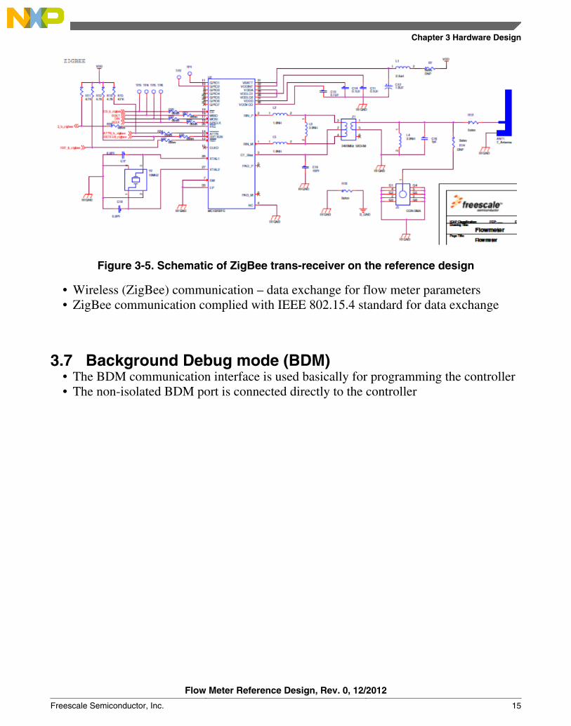
Figure 3-5. Schematic of ZigBee trans-receiver on the reference design
• Wireless (ZigBee) communication – data exchange for flow meter parameters• ZigBee communication complied with IEEE 802.15.4 standard for data exchange
3.7 Background Debug mode (BDM)• The BDM communication interface is used basically for programming the controller• The non-isolated BDM port is connected directly to the controller
Chapter 3 Hardware Design
Flow Meter Reference Design, Rev. 0, 12/2012
Freescale Semiconductor, Inc. 15

Figure 3-6. Photograph of PE micro USB multilink• PE’s USB multilink is a debug interface that allows a PC to access the background• BDM on controller MC9S08GW64• It connects between a USB port on a windows machine and the standard 6 pin berg
debug connector on the target• The user can take advantage of the BDM to halt normal processor execution and use
a PC to control the controller• The user can then directly control the target’s execution, read/write registers and
memory values, debug code on the controller, and program internal or externalFLASH memory devices
Background Debug mode (BDM)
Flow Meter Reference Design, Rev. 0, 12/2012
16 Freescale Semiconductor, Inc.

Figure 3-7. Circuit of BDM 6-pin connector
3.8 Microcontroller requirements
3.8.1 Crystal requirements
The external 32.768 kHz is a crystal used for the RTC, the same clock is multiplied bythe FLL which is internal to the controller to provide clock to core, bus, and peripherals.
3.8.2 LCD requirements
The LCD driver of the controller requires three ceramic capacitors whose typical value is0.1 μF for LCD bias voltages and a 0.1 μF ceramic capacitor for the LCD charge pump.
Chapter 3 Hardware Design
Flow Meter Reference Design, Rev. 0, 12/2012
Freescale Semiconductor, Inc. 17

3.9 Assembled printed circuit board
Figure 3-8. Assembled board
Assembled printed circuit board
Flow Meter Reference Design, Rev. 0, 12/2012
18 Freescale Semiconductor, Inc.

Chapter 4Software Design
4.1 IntroductionThis section describes the software design for the flow meter application. The softwaredesign consists mainly of the flow calculation, database, user interface, andcommunication modules. This chapter aims to explain the software design. The softwarearchitecture is a custom kernel running on an MC9S08GW64 controller. The controlleruses the external RTC clock source and internal FLL to generate the system clock ofapproximately 2 MHz.
The software has following main modules:• Flow Calculation Module• Database Management Module• User Interface Module• Communication Module
4.2 Block diagramThe following figure shows the block diagram of MC9S08GW64-based flow metersoftware:
Flow Meter Reference Design, Rev. 0, 12/2012
Freescale Semiconductor, Inc. 19

Figure 4-1. Block diagram of software architecture
4.3 Data flow diagramThe following figure shows the data flow diagram of MC9S08GW64-based flow metersoftware architecture
Data flow diagram
Flow Meter Reference Design, Rev. 0, 12/2012
20 Freescale Semiconductor, Inc.

Figure 4-2. Data flow diagram
4.4 Hardware resource allocationTable 4-1. Hardware Resource Allocation
MC9S08GW64 inbuilt block Description
PCNT Used to count the sensor output pulses and calculate the flow
Flash Used to store the flow
Timer (MTIM1) Used for interrupt generation to switch off the LCD after fewseconds
LCD Used to drive the LCD screen to display the flow on LCDscreen
SPI Used to communicate with ZigBee hardware
IRTC Used for time keeping
Tamper Used as a user switch
Chapter 4 Software Design
Flow Meter Reference Design, Rev. 0, 12/2012
Freescale Semiconductor, Inc. 21

4.5 Flow Calculation
4.5.1 OverviewThe Flow Calculation Module of the Freescale's Reference Flow Meter performs thefollowing functions:
1. PCNT module counts the pulses from the flow sensor output.2. Sends an interrupt to the MCU on PCNT overflow.3. Computes the flow for the interval.4. Accumulates the flow in a variable.
4.5.2 Measurement parametersThe following are the measurable parameters of MC9S08GW64-based Reference FlowMeter design.
• Accumulated flow for the entire interval when the meter is running• Current month’s flow• Date and time
4.5.3 PCNT Module
PCNT or position counter is a low-power pulse sequence counter. Once configured, it iscapable of working independent of the CPU in stop3 or stop4 modes. The PCounteraccumulates the valid pulses input to it. The PCounter interfaces to various rotatorysensors that provide it with necessary pulse sequence to determine the flow direction andquantity of the flow.
4.5.3.1 Summary of key features• Supports interfacing to one-, two- or three-pin rotatory sensor.• Supports 180 degree, Gray and Binary Decoding mode. Two-Signal Gray mode is
also called as Quadrature mode.• Able to filter sensor signals with programmable filter width.• Able to detect and generate interrupts on an invalid sequence.• Generates interrupts on counter overflow.• Generates required signaling to activate sensors.• Generates asynchronous interrupt to wake MCU from low-power modes.
Flow Calculation
Flow Meter Reference Design, Rev. 0, 12/2012
22 Freescale Semiconductor, Inc.

• Able to function independently in Stop mode.• Modulus registers to interrupt CPU on specific count or full count.• Able to function as limited capability PWM (that is, edge- or centre-aligned PWM).• Internal counter can function as an atomic counter which increments on each IPS
writes and generates an interrupt on counter overflow.
4.5.3.2 Initialization sequenceBefore the PCNT module can be used to count pulses, an initialization procedure must beperformed. A typical sequence is as follows:
• Enable clock to PCNT module.• Program PCNT_PWM_MOD, PCNT_PWM_CH1_VAL and
PCNT_PWM_CH2_VAL registers for proper generation of sensor activation signaland sampling signal or PWM signals.
• Program the PCNT_CTRL register with the required filter value, interrupt enablers,PWM mode, and channel selection with PCNT_EN 1’b1.
• PCNT_PWM_MOD, PCNT_PWM_CH1 and PCNT_PWM_CH2 get locked whenthe PCNT_EN bit of PCNT_CTRL is asserted. Users are not able to update theseregisters till PCNT_EN = 1’b1.
4.5.3.3 Pseudo-Code for PCNT initialization
In this example, the PCNT module is set up to perform a single 16-bit conversion atnormal power with a long sample time on input channel 1, where the internal ADCKclock is derived from the bus clock divided by 1.
PCNT_CTRL = 0x2400 (0 0 1 0 0 1 0 0 0 0 0 0 0 0 0 0)
Bit 15 SINVIE 0 State invalid event does not generate an interrupt.
Bit 14 RCOVFIE 0 RCounter overflow event does not generate an interrupt.
Bit 13 FCOVFIE 1 FCounter overflow event generates an interrupt.
Bit 12-11 MODE 00 PCounter operates in binary mode.
Bit 10-8 CHANNEL_SEL 100 Selects PCNT Channel 2.
Bit 7 PCNT_EN 0 PCounter is disabled.
Bit 6 DIR 0 Direction bit.
Bit 5 POL 0 Low-true pulses (set output on compare-up) on Ch1 and Ch2.
Bit 4 CPWMS 0 Ch1 and Ch2 operate as a edge-aligned PWM.
Bit 3-0 FILTER VALUE 0000 Filtering operation disabled.
Chapter 4 Software Design
Flow Meter Reference Design, Rev. 0, 12/2012
Freescale Semiconductor, Inc. 23

PCNT_FCMOD_H = 0x00 (0 0 0 0 0 0 0 0)
PCNT_FCMOD_L = 0xFF (1 1 1 1 1 1 1 1)
The PCNT_FCMOD modulo register contains the modulo value for the FCounter.
After the FCounter reaches the modulo value, it resumes counting from 0x0000,
and the overflow flag FCOVF of PCNT_STATUS becomes set.
PCNT_CTRL_PCNT_EN 1 To enable the PCNT module
4.5.4 Calculation and accumulation process
The position counter keeps on counting the pulses and when the counter overflows, aninterrupt is generated that wakes up the MCU and it calculates the amount of fluid thathas flown in the time interval. The flow calculated in the given interval is accumulated inthe variables.
4.6 Database
4.6.1 Overview• Reference Flow Meter design has flash memory inside the MCU• Flash memory storage parameters
• Monthwise Accumulated Flow• Accumulated Flow• Month and Month’s flow when the LVD occurs
Database
Flow Meter Reference Design, Rev. 0, 12/2012
24 Freescale Semiconductor, Inc.

4.6.2 Block diagram
Figure 4-3. Database block diagram
4.6.3 Implementation• IRTC is used for time keeping and it generates an interrupt when a month expires.• As soon as a month is over, the flow accumulated in that month is updated and stored
in the flash memory using the flash driver.• The monthwise flow keeps on updating in the flash and at any time the monthwise
profile of the flow can be retrieved from the flash using flash driver.• On occurrence of LVD (Low Voltage Detect), the flash is updated with the month,
flow in that month, and the flow accumulated till date.
4.7 User Interface
4.7.1 Overview• The User Interface Module comprises LCD, User switch, and its respective drivers.• Custom LCD specific for flow metering application• Meter has a user key to display the date and the current month’s flow
Chapter 4 Software Design
Flow Meter Reference Design, Rev. 0, 12/2012
Freescale Semiconductor, Inc. 25
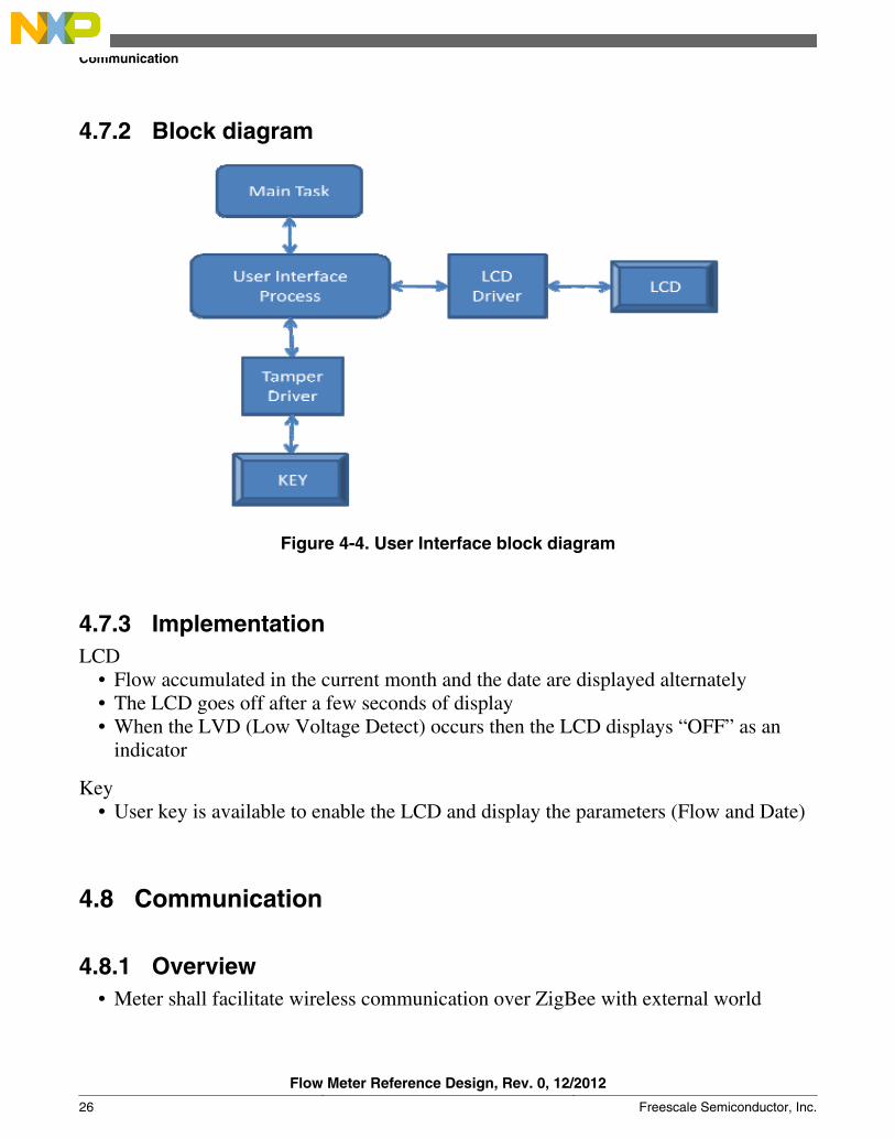
4.7.2 Block diagram
Figure 4-4. User Interface block diagram
4.7.3 ImplementationLCD
• Flow accumulated in the current month and the date are displayed alternately• The LCD goes off after a few seconds of display• When the LVD (Low Voltage Detect) occurs then the LCD displays “OFF” as an
indicator
Key• User key is available to enable the LCD and display the parameters (Flow and Date)
4.8 Communication
4.8.1 Overview• Meter shall facilitate wireless communication over ZigBee with external world
Communication
Flow Meter Reference Design, Rev. 0, 12/2012
26 Freescale Semiconductor, Inc.

• On other side, a handheld unit supporting ZigBee shall be used for communicationpurpose.
• Transmission and reception by interrupt method.
4.8.2 Block diagram
Figure 4-5. Communication block diagram
4.8.3 ImplementationZigBee interface
• IEEE 802.15.4 standard used for data exchange• A RF antenna is used for the interface between the meter and the handheld device
connected to PC for communication• Transmission and reception is on interrupt based. Reception is disabled until the
received packet is processed.• MCU uses SPI interface to communicate with the ZigBee hardware• The block diagram below explains the flow of ZigBee communication
Chapter 4 Software Design
Flow Meter Reference Design, Rev. 0, 12/2012
Freescale Semiconductor, Inc. 27

Figure 4-6. ZigBee communication diagram
Communication
Flow Meter Reference Design, Rev. 0, 12/2012
28 Freescale Semiconductor, Inc.

Appendix ASchematic and LayoutA.1 Schematic
Figure A-1. Schematic
A.2 Layout
A.2.1 Silkscreen top
Flow Meter Reference Design, Rev. 0, 12/2012
Freescale Semiconductor, Inc. 29

Figure A-2. Silkscreen – top
Flow Meter Reference Design, Rev. 0, 12/2012
30 Freescale Semiconductor, Inc.

Figure A-3. Silkscreen – bottom
Appendix A Schematic and Layout
Flow Meter Reference Design, Rev. 0, 12/2012
Freescale Semiconductor, Inc. 31
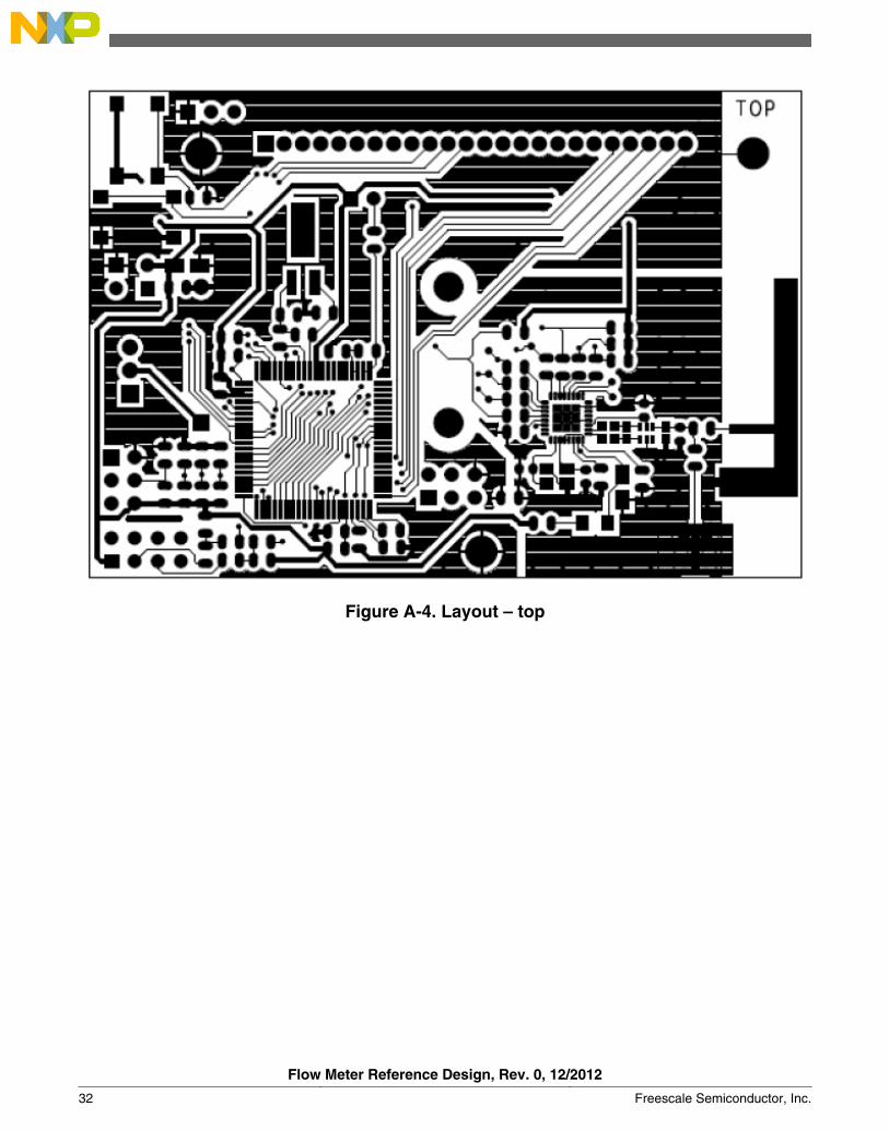
Figure A-4. Layout – top
Flow Meter Reference Design, Rev. 0, 12/2012
32 Freescale Semiconductor, Inc.

Figure A-5. Layout – bottom
Flow Meter Reference Design, Rev. 0, 12/2012
Freescale Semiconductor, Inc. 33

Flow Meter Reference Design, Rev. 0, 12/2012
34 Freescale Semiconductor, Inc.

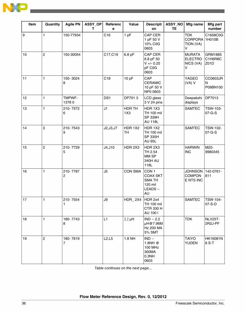
Appendix BBill of Material
Item Quantity Agile PN ASSY_OPT
Reference
Value Description
ASSY_NOTE
Mfg name Mfg partnumber
1 1 510-75678 ANT1 F_Antenna PCB FANTENNA,NO PARTORDER
NO PARTTOORDER
NOT APART
2 3 280-76468 BH1,BH2,BH3
MOUNTING HOLE
MOUNTING HOLEDRILL 108PAD 140PLATEDTH NOPART TOORDER
NO PARTTOORDER
MountingHole - 108mil DrillPTH
3 1 801-75636 BT1 BATTERYHOLDER
BATTERYHOLDER2XAA TH
KEYSTONEELECTRONICS
2462
4 9 150-75599 C1,C2,C3,C4,C5,C9,C21,C22,C23
0.1 μF CAP CER0.1 μF 25V 10%X7R 0805
PANASONIC-ECG
ECJ-2VB1E104K
5 5 150-78252 C6,C11,C13,C14,C15
0.1 μF CAP CER0.1μF 16 V10% X7R0805
Panasonic ECJ2VB1C104K
6 1 150-75055 C7 10 μF CAP TANT10 μF 16 V10% --3216-18
AVX TAJA106K016R
7 2 150-75202 C8,C10 22 pF CAP CER22 pF 50 V5% C0G0805
KEMET C0805C220J5GAC
8 1 150-30310 C12 1.0 μF CAP TANT1.0 μF 16V 20% --3216-18
KEMET T491A105M016AT
Table continues on the next page...
Flow Meter Reference Design, Rev. 0, 12/2012
Freescale Semiconductor, Inc. 35
Item Quantity Agile PN ASSY_OPT
Reference
Value Description
ASSY_NOTE
Mfg name Mfg partnumber
9 1 150-77934 C16 1 pF CAP CER1 pF 50 V10% C0G0603
TDKCORPORATION (VA)V
C1608C0G1H010B
10 2 150-30054 C17,C19 6.8 pF CAP CER6.8 pF 50V +/- 0.25pF C0G0603
MURATAELECTRONICS (VA)V
GRM1885C1H6R8CZ01D
11 1 150- 30248
C18 10 pF CAPCERAMIC10 pF 50 VNP0 0603
YAGEO(VA) V
CC0603JRNP09BN100
12 1 TMPWF-1378 0
DS1 DP701 3 LCD glass3 V 24 pins
Deepakshidisplays
DP7013
13 1 210- 75726
J1 HDR TH1X3
HDR 1X3TH 100 milSP 339HAU 118L
SAMTEC TSW-103-07-G-S
14 3 210- 75439
J2,J3,J7 HDR 1X2TH
HDR 1X2TH 100 milSP 335HAU 95L
SAMTEC TSW-102-07-G-S
15 2 210- 77295
J4,J10 HDR 2X3 HDR 2X3TH 2.54MM SP340H AU118L
HARWININC
M20-9980345
16 1 210- 77872
J5 CON SMA CON 1COAX SKTSMA TH120 milLEADS --AU
JOHNSONCOMPONE NTS INC
142-0761-811
17 1 210- 75541
J9 HDR_ 2X4 HDR 2x4TH 100 milCTR 330 HAU 100 l
SAMTEC TSW-104-07-S-D
18 1 180- 77438
L1 2.2 μH IND -- 2.2μ[email protected] 200 MA5% SMT
TDK NLV25T-2R2J-PF
19 2 180- 76197
L2,L5 1.8 NH IND --1.8NH @100 MHz300MA0.3NH0603
TAIYOYUDEN
HK16081N8 S-T
Table continues on the next page...
Flow Meter Reference Design, Rev. 0, 12/2012
36 Freescale Semiconductor, Inc.

Item Quantity Agile PN ASSY_OPT
Reference
Value Description
ASSY_NOTE
Mfg name Mfg partnumber
20 2 180- 77416
L3,L4 3.9 NH IND [email protected]
TAIYOYUDEN
HK16083N9 S-T
21 1 470- 75442
DN P R1 0 RES MFZEROOHM 1/8W-- 0805
YAGEOAMERICA
RC0805JR- 070RL
22 7 470- 75442
R2,R3,R5,R17,R18,R32,R33
0 RES MFZEROOHM 1/8W-- 0805
YAGEOAMERICA
RC0805JR- 070RL
23 1 470- 78687
R4 10 M RES MF10.0M1/8W 1%0805
YAGEOAMERICA
RC0805FR- 0710ML
24 1 470- 80195
R6 6.2 M RES MF6.2M 1/8W5% 0805
PANASONI C
ERJ6GEYJ62 5 V
25 2 470- 76111
DN P R7,R14 0 ohm RES 0.0OHM 1/8W5% 0805SMD
YAGEO(VA) V
RC0805JR- 070RL
26 2 470- 75904
R8,R10 10K RES MF10K 1/8W5% 0805
Yageo RC0805JR- 0710KL
27 6 470- 75908
R11,R13,R15,R16,R34,R35
4.7K RES MF4.7K 1/8W5% 0805
Yageo RC0805JR- 074K7L
28 10 470-76111 R12,R19,R20,R21,R22,R23,R24,R25,R26,R27
0 ohm RES 0.0OHM 1/8W5% 0805SMD
YAGEO(VA) V
RC0805JR-070RL
29 4 470-75904 R28,R29,R30,R31
10K RES MF10K 1/8W5% 0805
YAGEOAMERICA
RC0805JR-0710KL
30 1 510-30026 SW1 25136 N SW SPDTSLD 125 V4A TH
APEMCOMPONENTS
25136NAH
31 2 510-75922 SW2,SW3 PTS645 SW SPSTMOM NOPB 12 V50MA SMT
ITTCANNON
PTS645SL50SMTRLFS
Table continues on the next page...
Appendix B Bill of Material
Flow Meter Reference Design, Rev. 0, 12/2012
Freescale Semiconductor, Inc. 37

Item Quantity Agile PN ASSY_OPT
Reference
Value Description
ASSY_NOTE
Mfg name Mfg partnumber
32 6 280-75148 TP1,TP2,TP3,TP4,TP5,TP6
TESTPOINT
TESTPOINTPAD 35 milSMT, NOPART TOORDER
NA NA
33 1 TMP-WF-11879
U1 MC9S08GW64
IC MCU 8bit 3 VLQFP 80
FreescaleSemiconductor
MC9S08LGW64
34 1 312-76396 U2 MC13202FC
IC XCVR2.4 GHz2/3.4 VQFN32
FREESCALESEMICONDUCTOR
MC13202FC
35 1 230-77671 Y1 32.768 kHz XTAL32.768 kHzRSN --SMT
AbraconCorporation
AB26TRB-32.768 kHz
36 1 230-75677 Y2 16 MHz XTAL16MHZFIXED --SMT3.2X2.5MM
NDK NX3225SA-16.000000MHz
37 1 560-75093 Z1 2400 MHz50 ohm
XFMRBALUN2400+/-100MHz SMT
Flow Meter Reference Design, Rev. 0, 12/2012
38 Freescale Semiconductor, Inc.

How to Reach Us:
Home Page:www.freescale.com
Web Support:http://www.freescale.com/support
USA/Europe or Locations Not Listed:Freescale SemiconductorTechnical Information Center, EL5162100 East Elliot RoadTempe, Arizona 85284+1-800-521-6274 or +1-480-768-2130www.freescale.com/support
Europe, Middle East, and Africa:Freescale Halbleiter Deutschland GmbHTechnical Information CenterSchatzbogen 781829 Muenchen, Germany+44 1296 380 456 (English)+46 8 52200080 (English)+49 89 92103 559 (German)+33 1 69 35 48 48 (French)www.freescale.com/support
Japan:Freescale Semiconductor Japan Ltd.HeadquartersARCO Tower 15F1-8-1, Shimo-Meguro, Meguro-ku,Tokyo 153-0064Japan0120 191014 or +81 3 5437 [email protected]
Asia/Pacific:Freescale Semiconductor China Ltd.Exchange Building 23FNo. 118 Jianguo RoadChaoyang DistrictBeijing 100022China+86 10 5879 [email protected]
Document Number: DRM138Rev. 0, 12/2012
Information in this document is provided solely to enable system and softwareimplementers to use Freescale Semiconductors products. There are no express or impliedcopyright licenses granted hereunder to design or fabricate any integrated circuits orintegrated circuits based on the information in this document.
Freescale Semiconductor reserves the right to make changes without further notice to anyproducts herein. Freescale Semiconductor makes no warranty, representation, orguarantee regarding the suitability of its products for any particular purpose, nor doesFreescale Semiconductor assume any liability arising out of the application or use of anyproduct or circuit, and specifically disclaims any liability, including without limitationconsequential or incidental damages. "Typical" parameters that may be provided inFreescale Semiconductor data sheets and/or specifications can and do vary in differentapplications and actual performance may vary over time. All operating parameters,including "Typicals", must be validated for each customer application by customer'stechnical experts. Freescale Semiconductor does not convey any license under its patentrights nor the rights of others. Freescale Semiconductor products are not designed,intended, or authorized for use as components in systems intended for surgical implantinto the body, or other applications intended to support or sustain life, or for any otherapplication in which failure of the Freescale Semiconductor product could create asituation where personal injury or death may occur. Should Buyer purchase or useFreescale Semiconductor products for any such unintended or unauthorized application,Buyer shall indemnify Freescale Semiconductor and its officers, employees, subsidiaries,affiliates, and distributors harmless against all claims, costs, damages, and expenses, andreasonable attorney fees arising out of, directly or indirectly, any claim of personal injuryor death associated with such unintended or unauthorized use, even if such claims allegesthat Freescale Semiconductor was negligent regarding the design or manufacture ofthe part.
RoHS-compliant and/or Pb-free versions of Freescale products have the functionality andelectrical characteristics as their non-RoHS-complaint and/or non-Pb-free counterparts.For further information, see http://www.freescale.com or contact your Freescalesales representative.
For information on Freescale's Environmental Products program, go tohttp://www.freescale.com/epp.
Freescale™ and the Freescale logo are trademarks of Freescale Semiconductor, Inc.All other product or service names are the property of their respective owners.
© 2012 Freescale Semiconductor, Inc.